international civil aviation organization asia … _ispacg_ver… · international civil aviation...
TRANSCRIPT

HIGH FREQUENCY MANAGEMENT GUIDANCE MATERIAL FOR
THE SOUTH PACIFIC REGION
Version 1.0
(Adopted by APANPIRG/21 – September 2010)
INTERNATIONAL CIVIL AVIATION ORGANIZATION
ASIA AND PACIFIC OFFICE

Reference: ICAO APAC Regional Guidance Material GM-AMS001-Part 1
ASIA/PACIFIC AIR NAVIGATION PLANNING AND IMPLEMENTATION REGIONAL GROUP
September 2010
Version 1.0 April 2010
High Frequency Management Guidance Material
For the South Pacific Region
APANPIRG/21
Appendix K to the Report on Agenda Item 3.4

HF Management Guidance Material V 1.0
14/04/2010 ISPACG HF SP 6 Working Group Page 3
APX K - HF radio GM ISPACG Ver 1 0 april 10 (2) Version 1.0 - 2003
Document identification
Reference: HF Guidance projet ISPACG version 1.0 april 10.doc
Title: HF Frequency Management Guidance Materiel for the South Pacific Region
Edited by:
Editor: Antoine Guirado
Date: 14 april 2010
Published by: ISPACG
Contact: Service d’Etat de l’Aviation Civile en Polynesie Française Service Navigation Aérienne Division Technique BP 6011 FAAA 98702 FAAA Phone: +689 861033 Fax: +689 861039 Email: [email protected]
Obs:
This Document was created and corrected with the collaboration of all the others members of the working group :
Allan London
Airways New Zealand
Tim Halpin
Airways New Zealand
Tammy Callahan
ARINC [email protected]
David Gibson
Airport Fiji Limited
Ray Farmer
AirServices Australia
HF Management Guidance Material V 1.0
14/04/2010 ISPACG HF SP 6 Working Group Page 4
APX K - HF radio GM ISPACG Ver 1 0 april 10 (2) Version 1.0 - 2003
Table of Contents
DOCUMENT IDENTIFICATION .............................................................................................................................. 3
TABLE OF CONTENTS .......................................................................................................................................... 4
CHANGE RECORD ................................................................................................................................................. 6
ACKNOWLEDGEMENTS ....................................................................................................................................... 7
PREFACE ................................................................................................................................................................ 8
LIST OF ACRONYMS ............................................................................................................................................. 9
1 INTRODUCTION ........................................................................................................................................... 11
1.1 PURPOSE OF THE DOCUMENT .............................................................................................................. 11
2 OPERATIONAL CONCEPT .......................................................................................................................... 12
2.1 OVERVIEW .......................................................................................................................................... 12 2.2 HF MEDIUM CHARACTERISTICS ............................................................................................................ 12 2.3 RADIOTELEPHONY NETWORK ............................................................................................................... 13 2.3.1 DEFINITION ..................................................................................................................................... 13 2.3.2 SP 6 RADIOTELEPHONY NETWORK COMPOSITION ........................................................................... 13 2.3.3 PRINCIPLES OF NETWORK OPERATION ............................................................................................. 14 2.3.4 FREQUENCIES TO BE USED .............................................................................................................. 14 2.3.5 ESTABLISHMENT OF COMMUNICATIONS ............................................................................................. 15 2.3.6 TRANSFER OF COMMUNICATIONS ..................................................................................................... 15 2.3.7 COMMUNICATIONS FAILURE ............................................................................................................. 16 2.4 SELCAL OPERATION .......................................................................................................................... 16
3 SP6 FREQUENCIES ALLOTMENT PLAN ................................................................................................... 17
3.1 FREQUENCY ALLOTMENT PLAN FOR THE AERONAUTICAL MOBILE SERVICE (AMS) ................................. 17 3.1.2 MAJOR WORLD AIR ROUTE AREA – SOUTH PACIFIC (MWARA - SP)................................................. 17 3.1.3 MWARA – SP FREQUENCIES .......................................................................................................... 18 3.1.4 RDARA NETWORKS IN THE SOUTH PACIFIC AREA ............................................................................. 19 3.1.5 VOLMET STATIONS IN THE SOUTH PACIFIC. .................................................................................... 22 3.2 FREQUENCY ALLOCATION PRINCIPLES .................................................................................................. 23
4 FIR COORDINATES AND MAPS ................................................................................................................. 24
4.1 BRISBANE FIR ................................................................................................................................. 24 4.2 AUCKLAND FIR ................................................................................................................................ 25 4.3 NADI FIR ........................................................................................................................................... 26 4.4 OAKLAND FIR ................................................................................................................................. 27 4.5 TAHITI FIR ........................................................................................................................................ 28
5 HF PROPAGATION PREDICTION ............................................................................................................... 29
5.1 AUSTRALIAN SPACE WEATHER AGENCY ................................................................................... 29 5.2 BRISBANE FIR ................................................................................................................................. 29 5.3 AUCKLAND FIR ................................................................................................................................ 29 5.4 NADI FIR ........................................................................................................................................... 29 5.5 OAKLAND FIR .................................................................................................................................. 29 5.6 TAHITI FIR ........................................................................................................................................ 29

HF Management Guidance Material V 1.0
14/04/2010 ISPACG HF SP 6 Working Group Page 5
APX K - HF radio GM ISPACG Ver 1 0 april 10 (2) Version 1.0 - 2003
6 GENERAL NOTES ........................................................................................................................................ 30
6.1 HOURS OF SERVICE ............................................................................................................................. 30 6.2 POINTS OF CONTACT ........................................................................................................................... 30 6.3 COORDINATION PRINCIPLES ................................................................................................................. 30 6.4 POOR HF PROPAGATION CONDITIONS .................................................................................................. 30 6.5 HF OPERATOR .................................................................................................................................... 30
APPENDIX A - HF MEDIUM CHARACTERISTICS ............................................................................................ 32
APPENDIX B-1 - BRISBANE RADIO STATION INFORMATION ...................................................................... 37
APPENDIX B-2 - AUCKLAND RADIO STATION INFORMATION ...................................................................... 39
APPENDIX B-3 - NADI RADIO STATION INFORMATION ................................................................................. 41
APPENDIX B-4 - SAN FRANCISCO RADIO STATION INFORMATION ............................................................ 43
APPENDIX B-5 - TAHITI CONTROL STATION INFORMATION ........................................................................ 46
LIST OF FIGURES ................................................................................................................................................ 48
LIST OF TABLES .................................................................................................................................................. 48

HF Management Guidance Material V 1.0
14/04/2010 ISPACG HF SP 6 Working Group Page 6
APX K - HF radio GM ISPACG Ver 1 0 april 10 (2) Version 1.0 - 2003
Change Record
This chart provides records of changes to Version 0.1 and forward.
Paragraph(s) Explanation
.Version 0.2
Document
identification
Callahan instead of Callaha
Document
identification
HF Frequency Management Guidance Materiel for the
South Pacific Region instead of HF Frequency
Management Guidance Materiel
Acknowled-
gements
Acknowledgement instead of thank you
1.1.1 South Pacific instead of North Atlantic
2.3.2 SP 6 instead of SP
3.1.4.1.1 figure 2 Appendix instead of appendic
3.1.4.3.1 figure 4 New map of the sectors in the NZZO FIR
3.1.4.6.1 Selected instead of choose
3.1.4.4.1 HF frequencies datas move to paragraph 3.1.4.3.1
4.2.1 figure 7 New map of New Zealand FIR
4.3.1 figure 8 New map of Nadi FIR
5.5.1 Web link from www.ips.gov.au for SFO station
Appendix B1 Datas from Airservices Australia
Added the SATCOM SHORT CODE Nr. : 45 03 02
Appendix B.2 Country code for New Zealand
Added the SATCOM SHORT CODE Nr. : 45 12 01
Appendix B.5 Added the SATCOM SHORT CODE Nr. : 42 27 90
.Version 0.3
3.1.4.4.1 Added RDARA 9B
3.1.4.51 Changed “there is no RDARA activity in the KZAK FIR”,
instead of “There isn’t a RDARA network in activity in
the KZAK FIR”
Appendix B.2 Changed shift managers Robin Lee instead of Julie
Wagner
.Version 0.4 Appendix B.5 Tahiti Control instead of Tahiti Radio
.Version 0.5 3.1.5 Added Brisbane Volmet station
.Version 1.0 Appendix B.4 Corrections on frequencies , stations and duty manager

HF Management Guidance Material V 1.0
14/04/2010 ISPACG HF SP 6 Working Group Page 7
APX K - HF radio GM ISPACG Ver 1 0 april 10 (2) Version 1.0 - 2003
Acknowledgements The HF working group would like to acknowledge the OACI bureau of Paris and M. Cabral from the North Atlantic Systems Planning Group - Aeronautical Communications Group which accept that we re use part of the HF propagation theory published in the ICAO document NAT Doc 003 “High Frequency Management Guidance Material For the North Atlantic Region” and Mr. Hristo Hirvonen who autorize them to use his map of the SP MWARA in the first page of the document.

HF Management Guidance Material V 1.0
14/04/2010 ISPACG HF SP 6 Working Group Page 8
APX K - HF radio GM ISPACG Ver 1 0 april 10 (2) Version 1.0 - 2003
Preface This Document is published by the Informal South Pacific ATS Co-ordination Group, and managed by the High Frequency Working Group, and is for guidance. Regulatory material relating to South Pacific communications procedures is contained in relevant ICAO Documents and Annexes. Annex 10 – Volume II, ITU Radio Regulations, Regional Supplementary Procedures (Doc. 7030), FASID, NAT OPS Manual, State AIP and current NOTAM’s, which should be read in conjunction with the guidance material contained in this document. To assist with the editing of this document and to ensure the currency and accuracy of future editions, comments and suggestions for possible amendments should be sent to the editor, to the contact information included in the document identification section.

HF Management Guidance Material V 1.0
14/04/2010 ISPACG HF SP 6 Working Group Page 9
APX K - HF radio GM ISPACG Ver 1 0 april 10 (2) Version 1.0 - 2003
List of Acronyms
ACARS Aircraft Communication Addressing and Reporting System
ACC Area Control Centre
ACG Aeronautical Communications Group
ACID Aircraft Identification
AIP Aeronautical Information Publication
AFTN Aeronautical Fixed Telecommunication Network
AMS Aeronautical Mobile Service
ARINC Aeronautical Radio INC.
ARP Air Report Message
ATC Air Traffic Control
ATM Air Traffic Management
ATN Aeronautical Telecommunication Network
ATS Air Traffic Services
ATSMP Air Traffic Services Message Processor
ATSU Air Traffic Services Unit
CAA Civil Aviation Authority
CNS Communications, Navigation and Surveillance
EMG Emergency Message
FAP Frequency Allotment Plan
FDPS Flight Data Processing System
FIR Flight Information Region
FMC Flight Management Computer
FMS Flight Management System
GP General Purpose
GPS Global Positioning System
HF High Frequency (3 to 30 MHz)
ICAO International Civil Aviation Organization
ICD
ISPACG
Interface Control Document
Informal South Pacific ATS Coordinating Group
ITU International Telecommunications Union
LDOC Long Distance Operations Control
kHz Kilohertz
LF Low Frequency (30 to 300 kHz)
LUF Lowest Usable Frequency
MET Meteorological
MF Medium Frequency (300 to 3000 kHz)
MHz Megahertz
MUF Maximum Usable Frequency
MWAR Major World Air Route
MWARA Major World Air Route Area
NAT North Atlantic
NAT SPG North Atlantic Systems Planning Group
NOTAM Notice to Airmen
OCA Oceanic Control Area
POS ICAO Position Report Message
RDAR Regional and Domestic Air Routes

HF Management Guidance Material V 1.0
14/04/2010 ISPACG HF SP 6 Working Group Page 10
APX K - HF radio GM ISPACG Ver 1 0 april 10 (2) Version 1.0 - 2003
RDARA Regional and Domestic Air Route Area
R/T Radio-Telephony
SARPS
SEAC - PF
Standards and Recommended Practices
Service d’Etat de l’Aviation Civile en Polynésie Française
SELCAL Selective Calling System
SP
VHF
South Pacific
Very High Frequency (30 to 300 MHz)
VLF Very Low Frequency (3 to 30 kHz)
WP Waypoint Position
WPR Waypoint Position Reporting
HF Management Guidance Material V 1.0
14/04/2010 ISPACG HF SP 6 Working Group Page 11
APX K - HF radio GM ISPACG Ver 1 0 april 10 (2) Version 1.0 - 2003
1 Introduction
1.1 Purpose of the document
1.1.1 The purpose of this document is to provide a guidance methodology for the utilisation of the
Families and Frequencies employed by the Aeronautical Communication Stations on the South Pacific, to support a better management plan of the available families, frequencies and human resources, in order to increase the efficiency and capacity of the Communications Network.
1.1.2 It will also include information about HF frequencies for air-ground communications. In
addition, it will contain contact information for Aeronautical Stations.

HF Management Guidance Material V 1.0
14/04/2010 ISPACG HF SP 6 Working Group Page 12
APX K - HF radio GM ISPACG Ver 1 0 april 10 (2) Version 1.0 - 2003
2 Operational concept
2.1 Overview
2.1.1 The Aeronautical Mobile Service is a service reserved for air-ground communications
related with the safety and regularity of flights, flying primarily along national or international civil air routes.
2.1.2 In areas like the South Pacific, where VHF coverage is insufficient due to range limitation to
cover all portions of the routes flown, the use of HF frequencies are necessary because they provide long range communications coverage, not only for air-ground voice communications, but also for the broadcast of ATS or Meteo information.
2.1.3 For various reasons, some technical, others economical, environmental, physical, natural,
etc., coverage of a wide area by a single station with equipment located in a single place are impractical.
2.1.4 Taking these factors into account, the most practical option is to employ a number of
stations sharing a range of frequencies and working as a network to provide the facilities and services required for the AMS.
2.1.5 To work as a network the AMS should follow appropriate principles of operation, in order to
achieve the highest possible level of capacity and efficiency, otherwise, its purpose will not be achieved and the safety and regularity of flights will be affected.
2.2 HF medium characteristics
2.2.1 This section presents only a short description on the HF medium characteristics, a more
detail description can be found in Appendix A. 2.2.2 As a general rule, radio signals travel in straight lines, that is, they follow great circle paths
over the surface of the earth. Under certain circumstances, however, the path of a signal may change direction; this change of direction is called refraction. Refraction examples are coastal, atmospheric and ionospheric, and the amount of refraction varies considerably, depending on certain conditions. Those conditions could be a change in direction when a signal crosses a coastline (coastal refraction), a change in direction due to a variation in temperature, pressure and humidity, particularly at low altitude (atmospheric refraction), or a change in direction when the radio wave passes through an ionised layer (ionospheric refraction).
2.2.3 The ionosphere is still under investigation but it is known that several definite ionised layers
exist within it. During daytime hours there are four main ionisation layers designated D, E, F1 and F2 in ascending order of height. At night, when the sun’s radiation is absent, ionisation still persists but it is less intense, and fewer layers are found (D and F layers). Factors that affect the ionosphere layers is strength of the sun’s radiation, since it varies with latitude causing that the structure of the ionosphere varies widely over the earth’s surface, and the state of the sun, since sunspots affect the amount of ultra-violet radiation.

HF Management Guidance Material V 1.0
14/04/2010 ISPACG HF SP 6 Working Group Page 13
APX K - HF radio GM ISPACG Ver 1 0 april 10 (2) Version 1.0 - 2003
2.2.3.1 Maximum Usable Frequency (MUF) at night is much less than by day, because the
intensity of ionisation in the layer is less so than lower frequencies have to be used to produce the same amount of refractive bending and give the same critical angle and skip distance as by day. However, the signal attenuation in the ionosphere is also much less at night so the lower frequency needed is still usable. Hence the night frequency for a given path is about half of the day frequency, and shorter distances can be worked at night than by day while still using a single reflection from the F layer.
2.2.3.2 The MUF not only varies with path length and between day and night, but also with
season, meteor trails, sunspot state, and sudden ionospheric disturbances produced by eruptions on the sun. Because of the variations of MUF, HF transmitting stations have to use frequencies varying widely between about 2 and 20 MHz.
2.2.4 As consequence of this conditions, frequency band usage can be viewed in the following
table:
Areas Bands between: (MHz) Sharing conditions
MWARA area 3 and 6.6 Night propagation
9 and 11.3 Day propagation
Higher than 13 Day propagation
Table 1: Frequency band usage (ref. ITU Appendix 27 Aer2)
2.3 Radiotelephony Network
2.3.1 Definition
2.3.1.1 A radiotelephony network is defined as a group of radiotelephony aeronautical stations
which operate on and guard frequencies from the same family and which support each other in a defined manner to ensure maximum dependability of air-ground communications and dissemination of air-ground traffic
2.3.2 SP 6 Radiotelephony Network Composition
2.3.2.1 In the South Pacific 6 network there are five aeronautical stations, one per each of the
Oceanic FIR’s, responsible for the provision of air-ground communications as part of the Aeronautical Mobile Service. They are:
Brisbane Radio (Australia, Brisbane ACC), Auckland Radio (New Zealand, Auckland OACC), Nadi Radio (Fiji, Nadi ACC), San Francisco Radio (USA, Oackland OACC) and Tahiti Radio (French Polynesia, Tahiti OACC).

HF Management Guidance Material V 1.0
14/04/2010 ISPACG HF SP 6 Working Group Page 14
APX K - HF radio GM ISPACG Ver 1 0 april 10 (2) Version 1.0 - 2003
2.3.2.2 To support the air-ground communications of the AMS in the South Pacific 6 network, five
frequencies were allocated by the ITU (Appendix 27 Aer2), in different bands to ensure SP MWARA, continuous coverage.
2.3.2.3 To separate International and Domestics ( Regionals) flights some states use their own
RDARA network. (defined in paragraph 3.1.4)
2.3.3 Principles of Network Operation
2.3.3.1 The aeronautical stations of a radiotelephony network should assist each other in order to
provide the air-ground communication service required of the network by aircraft flying on the air routes for which the network is responsible.
2.3.3.2 When the network comprises a large number of stations, network communications for
flights on any individual route segment should be provided by selected stations, termed “regular stations” for that segment. In principle, the regular station will be those serving the locations immediately concerned with flights on that route segment, i.e. points of take-off and landing and appropriate flight information centres or area control centres.
2.3.3.3 In areas or on routes where radio conditions, length of flights or distance between
aeronautical stations require additional measures to ensure continuity of air-ground communications throughout the route segment, the regular stations should share between them a responsibility of primary guard whereby each station will provide the primary guard for that portion of the flight during which the messages from the aircraft can be handled most effectively by that station.
2.3.3.4 During its tenure of primary guard, each regular station should, among other things:
a) be responsible for designating suitable primary and secondary frequencies for its communications with the aircraft;
b) receive all position reports and handle other messages from and to the aircraft essential to the safe conduct of the flight;
c) be responsible for the action required in case of failure of communication.
2.3.4 Frequencies to be used
2.3.4.1 Aircraft stations shall operate on the appropriate radio frequencies. 2.3.4.2 The air-ground radio station shall designate the frequency(ies) to be used under normal
conditions by aircraft stations operating under its control. 2.3.4.3 In network operation, the initial designation of primary and secondary frequencies should
be made by the network station with which the aircraft makes pre-flight check or its initial contact after take-off. This station should also ensure that other network stations are advised, as required, of the frequency(ies) designated.

HF Management Guidance Material V 1.0
14/04/2010 ISPACG HF SP 6 Working Group Page 15
APX K - HF radio GM ISPACG Ver 1 0 april 10 (2) Version 1.0 - 2003
2.3.4.4 An aeronautical station when designating frequencies, should take into account the appropriate propagation data and distance over which communications are required.
2.3.4.5 If a frequency designated by an aeronautical station proves to be unsuitable, the aircraft
station should suggest an alternative frequency.
2.3.5 Establishment of communications
2.3.5.1 Aircraft stations shall, if possible, communicate directly with the air-ground control radio
station appropriate to the area in which the aircraft are flying. If unable to do so, aircraft stations shall use any relay means available and appropriate to transmit messages to the air-ground control radio station.
2.3.5.2 When normal communications from an aeronautical station to an aircraft station cannot be
established, the aeronautical station shall use any relay means available and appropriate to transmit messages to the aircraft station. If these efforts fail, the originator shall be advised.
2.3.5.3 When, in network operation, communication between an aircraft station and a regular
station has not been established after calls on the primary and secondary frequencies, aid should be rendered by one of the other regular stations for that flight, either by calling the attention of the station first called or, in case of a call made by an aircraft station, by answering the call and taking the traffic.
2.3.5.4 Other stations of the network should render assistance by taking similar action only if
attempts to establish communication by the regular stations have proved unsuccessful.
2.3.6 Transfer of communications
2.3.6.1 The transfer of primary guard from one station to the next will normally take place at the
time of the traversing of flight information region or control area boundaries, this guard being provided at any time, as far as possible, by the station serving the flight information centre or area control centre in whose area the aircraft is flying.
2.3.6.2 An aircraft station should be advised by the appropriate aeronautical station to transfer
from one radio frequency or network to another. In the absence of such advice, the aircraft station should notify the appropriate aeronautical station before such transfer takes place.
2.3.6.3 In the case of transfer from one network to another, the transfer should preferably take
place while the aircraft is in communication with a station operating in both networks to ensure continuity of communications. If, however, the change of network must take place concurrently with the transfer of communication to another network station, the transfer should be co-ordinated by the two network stations prior to advising or authorizing the frequency change. The aircraft should also be advised of the primary and secondary frequencies to be used after the transfer.

HF Management Guidance Material V 1.0
14/04/2010 ISPACG HF SP 6 Working Group Page 16
APX K - HF radio GM ISPACG Ver 1 0 april 10 (2) Version 1.0 - 2003
2.3.7 Communications failure
2.3.7.1 When an aircraft station fails to establish contact with the aeronautical station on the
designated frequency, it shall attempt to establish contact on another frequency appropriate to the route. If this attempt fails, the aircraft station shall attempt to establish communication with other aircraft or other aeronautical stations on frequencies appropriate to the route. In addition, an aircraft operating within a network shall monitor the appropriate VHF frequency for calls from nearby aircraft.
2.3.7.2 When an aeronautical station has been unable to establish contact with an aircraft station
after calls on the frequencies on which the aircraft is believed to be listening, it shall:
a) Request other aeronautical stations to render assistance by calling the aircraft and relaying traffic, if necessary;
b) Request aircraft on the route to attempt to establish communication with the aircraft and relay traffic, if necessary.
2.3.7.3 The air-ground control radio station shall notify the appropriate air traffic services unit and
the aircraft operating agency, as soon as possible, of any failure in air-ground communications.
2.4 SELCAL operation
2.4.1 With the selective calling system known as SELCAL, the voice call is replaced by the
transmission of coded tones to the aircraft over the radiotelephony channels. A single selective call consists of a combination of four pre-selected audio tones whose transmission requires approximately two seconds. The tones are generated in the aeronautical station coder and are received by a decoder connected to the audio output of the airborne receiver. Receipt of the assigned tone code activates a cockpit call system in the form of light and/or chime signals.

HF Management Guidance Material V 1.0
14/04/2010 ISPACG HF SP 6 Working Group Page 17
APX K - HF radio GM ISPACG Ver 1 0 april 10 (2) Version 1.0 - 2003
3 SP6 Frequencies Allotment Plan
3.1 Frequency Allotment Plan for the Aeronautical Mobile Service (AMS)
3.1.1 The frequencies allocated for use in the South Pacific, are based on the Frequency
Allotment Plan, for the MWARA - SP as defined on the “Appendix 27 Aer2 to the Radio Regulations – Frequency Allotment Plan for the Aeronautical Mobile (R) Service and Related Information”.
3.1.2 Major World Air Route Area – South Pacific (MWARA - SP)
3.1.2.1 The MWARA - SP is an area defined as the area from the from the South Pole through
the points 38° S 145° E, 00° 167° E, 00° 175° W, 22° N 158° W, 22° N 156° W, 00° 120° W to the South Pole, and can be viewed on Figure 1 (Ref. ITU Appendix 27 Aer2).
Figure 1 : MWARA – SP (Ref. ITU Appendix 27 Aer2)

HF Management Guidance Material V 1.0
14/04/2010 ISPACG HF SP 6 Working Group Page 18
APX K - HF radio GM ISPACG Ver 1 0 april 10 (2) Version 1.0 - 2003
3.1.3 MWARA – SP Frequencies
3.1.3.1 The frequencies allocated to the MWARA – SP includes a number of frequencies in a
range of bands designed to provide twenty-four hour area coverage and are contained in Table 2.
Frequency Bands
Area 3.5 4.7 5.6 6.6 9 10 11.3 13.3 18
kHz kHz kHz kHz kHz kHz kHz kHz kHz
3467 5559 8867 10084 11327 13300 17904
SP 5643
Frequency 3467 shared with MWARAs AFI, MID ,RDARAs 10B and 13D
Frequency 5559 shared with RDARAs 2A, 4A, 6G, 10E, 12G and 13J
Frequency 5643 shared with RDARA 3C
Frequency 8867 shared with RDARAs 6G, 10C, 13D and 13M
Frequency 10084 shared with MWARA EUR , RDARAs 6E and 13D
Frequency 11327 shared with RDARA 3B , 5 and 13C
Frequency 13300 shared with MWARAs CEP, CWP, NP and RDARA 4
Frequency 17904 shared with MWARAs CEP, CWP, NP and RDARA 4
Table 2 : Frequency bands of the MWARA – SP (Ref. ITU Appendix 27 Aer2)
3.1.3.2 The SP 6 NETWORK uses 13261 kHz instead of 13300 kHz. This change was endorsed
by ICAO in 1987 (refer ASIA/PAC FASID Doc 9673, 2001 Appendix Chart CNS4). The ITU-R Radio Regulations AP27/213 (WRC 2000) will be updated to reflect this change.
3.1.3.3 The SP 6 NETWORK use the following frequencies in kHz :
3467 5643 8867 13261 17904
Table 3 : HF Frequencies SP6 NETWORK ( in KHz)

HF Management Guidance Material V 1.0
14/04/2010 ISPACG HF SP 6 Working Group Page 19
APX K - HF radio GM ISPACG Ver 1 0 april 10 (2) Version 1.0 - 2003
3.1.4 RDARA networks in the South Pacific area
3.1.4.1 THE APPENDIX 27 ( REV. WRC-03 ) FROM THE ITU RR : 3.1.4.1.1 The ITU gives the definition of the South Pacific‘s RDARA 9.
Figure 2 : RDARA Map - South Pacific ( Appendix S27 ITU RR)
3.1.4.1.2 Regional and Domestic Air Route Area – 9 (RDARA-9)
From the South Pole along the 160° E meridian to 27° S. Then through the points 19° S 153° E, 10° S 145° E, 10° S 141° E, 00° 141° E, 00° 160° E, 03° 30' N 160° E, 03° 30' N 120° W. Then along the 120° W meridian to the South Pole.
3.1.4.1.3 Sub-Area 9B
From the point 00° 141° E through points 10° S 141° E, 10° S 145° E, 27° S 160° E, 27° S 157° W, 03° 30' N 157° W, 03° 30' N 160° E, 00° 160° E to the point 00° 141° E.
3.1.4.1.4 Sub-Area 9C
From the South Pole along the 170° W meridian to 03° 30' N. Then through the point 03° 30' N 120° W and along the 120° W meridian to the South Pole.
3.1.4.1.5 Sub-Area 9D
From the South Pole along the 160° E meridian to 27° S. Then through the point 27° S 170° W and along the 170° W meridian to the South Pole.
HF Management Guidance Material V 1.0
14/04/2010 ISPACG HF SP 6 Working Group Page 20
APX K - HF radio GM ISPACG Ver 1 0 april 10 (2) Version 1.0 - 2003
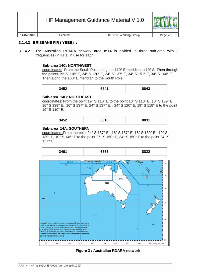
3.1.4.2 BRISBANE FIR ( YBBB) : 3.1.4.2.1 The Australian RDARA network area n°14 is divided in three sub-area with 3
frequencies (in KHz) in use for each.
Sub-area 14C: NORTHWEST coordinates: From the South Pole along the 110° E meridian to 19° S. Then through the points 19° S 118° E, 24° S 120° E, 24° S 137° E, 34° S 151° E, 34° S 160° E . Then along the 160° E meridian to the South Pole
3452 6541 8843
Sub-area 14B: NORTHEAST coordinates: From the point 19° S 110° E to the point 10° S 110° E, 10° S 139° E, 16° S 139° E, 16° S 137° E, 24° S 137° E, , 24° S 120° E, 19° S 118° E to the point 19° S 110° E.
3452 6610 8831
Sub-area 14A: SOUTHERN coordinates :From the point 24° S 137° E, 16° S 137° E, 16° S 139° E, 10° S 139° E, 10° S 145° E to the point 27° S 160° E, 34° S 160° E to the point 24° S 137° E.
3461 6565 8822
Figure 3 : Australian RDARA network

HF Management Guidance Material V 1.0
14/04/2010 ISPACG HF SP 6 Working Group Page 21
APX K - HF radio GM ISPACG Ver 1 0 april 10 (2) Version 1.0 - 2003
3.1.4.3 AUCKLAND FIR ( NZZO ): 3.1.4.3.1 New Zealand authorities don’t implement a RDARA network in the NZZO FIR.
However the following airports use HF frequencies from the RDARA 9B:
Figure 4 : Sectors in the NZZO FIR
- Rarotonga ( Cook sector) :
3425 6553 8846 11339
- Niue :
6553 8846
- Faleolo (Samoa sector):
3425 6553 8846 11339
- Fua’amotu ( Tonga sector):
3425 6553 8846 11339

HF Management Guidance Material V 1.0
14/04/2010 ISPACG HF SP 6 Working Group Page 22
APX K - HF radio GM ISPACG Ver 1 0 april 10 (2) Version 1.0 - 2003
3.1.4.4 NADI FIR ( NFFF): 3.1.4.4.1 The following RDARA network ( 9B) is operational in the Nadi FIR.( see map chap 4.3.1)
- Nadi :
3425 6553 8846 11339
- Funafuti:
6553 8846 11339
3.1.4.5 OACKLAND FIR ( KZAK): 3.1.4.5.1 There is no RDARA activity in the KZAK FIR. 3.1.4.6 TAHITI FIR ( NTTT): 3.1.4.6.1 The French civil Aviation in the French Polynesia (SEAC-PF) will create a RDARA
network with 3 HF frequencies in 2009. The frequencies are selected in RDARA 9C network from the ITU.
This future network will use the following frequencies (in KHz):
5481 8873 11312 or 11279
3.1.5 VOLMET Stations in the South Pacific.
VOLMET Stations broadcast meteorological bulletins in following HF frequencies (kHz):
3.1.5.1 Auckland VOLMET Station :
6679 8828 13282
3.1.5.2 Brisbane VOLMET Station :
6676 11387

HF Management Guidance Material V 1.0
14/04/2010 ISPACG HF SP 6 Working Group Page 23
APX K - HF radio GM ISPACG Ver 1 0 april 10 (2) Version 1.0 - 2003
3.2 Frequency allocation principles
3.2.1 Taking into account the characteristics of the HF medium, the general principles for
frequency assignment used by radio station personnel is as outlined in 2.2.4 and contained in Table 4.
Bands between: (MHz) Sharing conditions
3 and 6.6 Night propagation
9 and 11.3 Day propagation
Higher than 13 Day propagation
Table 4 : General principes for frequency assigment
3.2.2 As a general rule, when assigning primary and secondary frequencies, radio station
personnel should assign lower frequencies as primary and higher frequencies as secondary for aircraft flying away from the Station. Conversely, for aircraft routing towards the station, the higher frequencies should be assigned as primary and lower frequencies as secondary.
3.2.3 In circumstances were sunspot or solar flare activity is expected to affect propagation
conditions, the radio station personnel should always inform the flight crews and in addition to assigning the primary and secondary frequencies, they should advise the highest frequencies in use at the station as a precautionary measure.
3.2.4 In accordance with the principles governing transfer of communications as defined in
paragraph 2.3.6, stations sharing a common boundary should, whenever possible, assign common frequencies for the transfer of communications.
3.2.5 Aircraft routing along common boundaries, or flying a route or portion of a route within 60
NM of a common boundary, should be assigned frequencies common to the stations sharing those boundaries.

HF Management Guidance Material V 1.0
14/04/2010 ISPACG HF SP 6 Working Group Page 24
APX K - HF radio GM ISPACG Ver 1 0 april 10 (2) Version 1.0 - 2003
4 FIR coordinates and maps
4.1 BRISBANE FIR
.
4.1.1 The Brisbane FIR is an area from the South Pole through the points 38° S 145° E, 25°S 155° E 21° 163° E 00° 167° E, 00° 175° W, 22° N 158° W, 22° N 156° W, 00° 120° W to the South Pole.
Figure 5 : Map of Australian's FIR
4.1.2 The SP6 Network area is a part of the Brisbane FIR. The coordinates of this area are :
Lateral limits : 44 33 57S - 150 00 00E ; 45 00 00S -150 00 00E 45 00 00S - 163 00 00E ; 21 22 50S -163 00 00E 24 49 40S - 153 56 22E ; 24 59 04S -154 00 31E then along the minor arc of a circle of 150.00 NM radius centred on 27 21 57S -153 08 21E (BN/DME) to 29 49 13S -153 42 58E 30 40 20S -153 08 21E ; 32 53 01S -152 26 31E 33 30 06S -151 54 31E; then along the minor arc of a circle of 45.00 NM radius centred on 33 56 34S -151 10 51E (SY/DME) to 34 28 18S -151 49 23E 35 18 59S -152 55 50E; then along the minor arc of a circle of 120.00 NM radius centred on 34 57 00S -150 32 00E (NWA/TAC) to 36 56 43S -150 45 03E 38 11 19S -150 19 14E ; 43 00 00S -151 00 00E 43 51 03S -150 39 53E ; 44 33 57S -150 00 00E
HF Management Guidance Material V 1.0
14/04/2010 ISPACG HF SP 6 Working Group Page 25
APX K - HF radio GM ISPACG Ver 1 0 april 10 (2) Version 1.0 - 2003
Figure 6 : Map of Australia - HF Frequencies Areas
4.2 AUCKLAND FIR
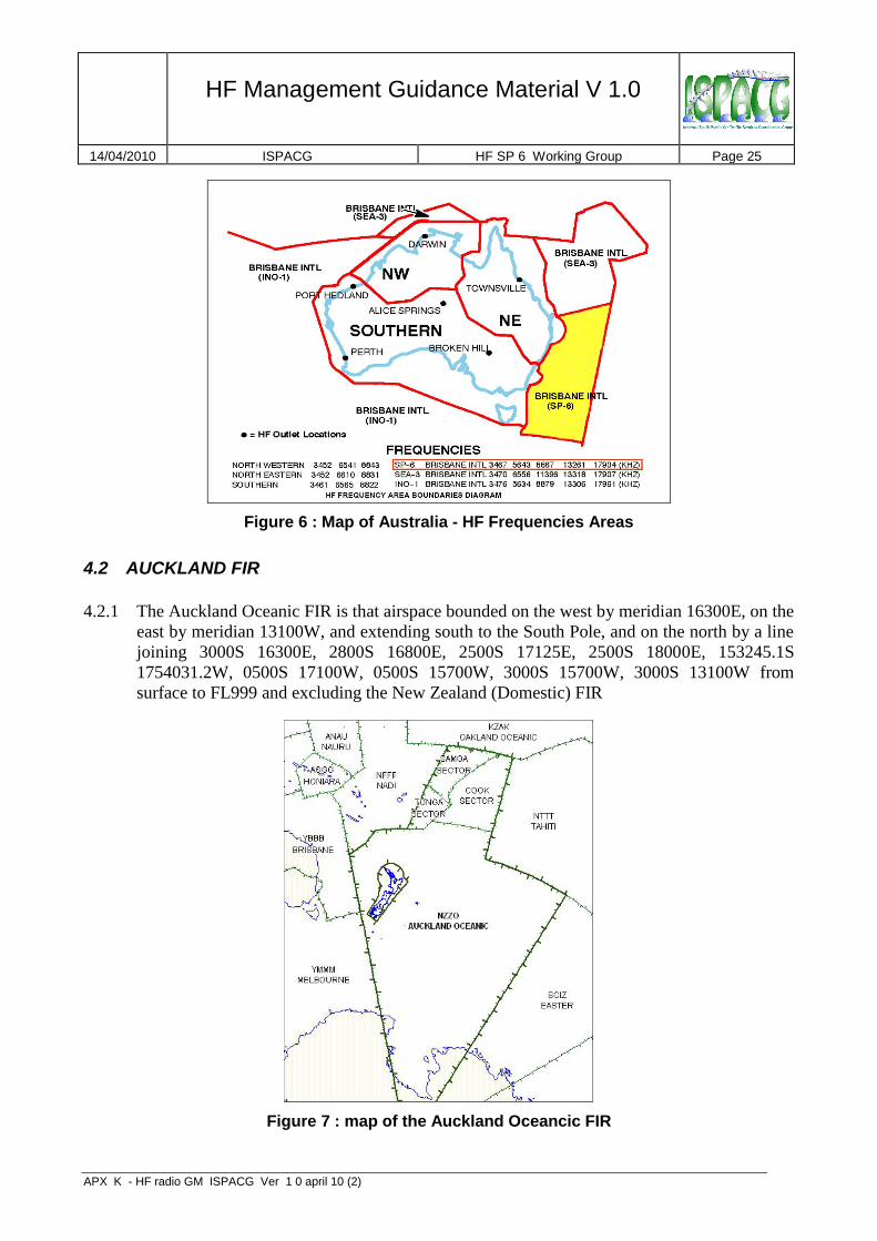
4.2.1 The Auckland Oceanic FIR is that airspace bounded on the west by meridian 16300E, on the
east by meridian 13100W, and extending south to the South Pole, and on the north by a line
joining 3000S 16300E, 2800S 16800E, 2500S 17125E, 2500S 18000E, 153245.1S
1754031.2W, 0500S 17100W, 0500S 15700W, 3000S 15700W, 3000S 13100W from
surface to FL999 and excluding the New Zealand (Domestic) FIR
Figure 7 : map of the Auckland Oceancic FIR

HF Management Guidance Material V 1.0
14/04/2010 ISPACG HF SP 6 Working Group Page 26
APX K - HF radio GM ISPACG Ver 1 0 april 10 (2) Version 1.0 - 2003
4.3 NADI FIR
4.3.1 The coordinates of the Nadi FIR are shown in the table 5 :
Name Horizontal imits Vertical limits
Nadi Flight Information
Region
N 03 30.0 - E 170 00.0 – N 03 30.0 - E 180 00.0 – S 05 00.0 - W 180 00.0 – S 05 00.0 - W 171 00.0 – S 25 00.0 - E 180 00.0 – S 25 00.0 - E 171 25.0 – S 28 00.0 - E 168 00.0 – S 30 00.0 - E 163 00.0 – S 17 40.0 - E 163 00.0 – S 14 00.0 - E 161 15.0 – S 14 00.0 - E 163 00.0 – S 10 00.0 - E 170 00.0 –
N 03 30.0 - E 170 00.0
Surface to 9500 ft
and
above FL460
New Caledonia
Sector
S 14 00.0 - E 165 15.0 – S 14 00.0 - E 163 00.0 – S 21 00.0 - E 170 30.0 – S 24 00.0 - E 170 30.0 – S 24 00.0 - E 163 00.0 – S 17 40.0 - E 163 00.0 –
S 14 00.0 – E 163 00.0 Surface to FL245
Xport Vila Sector
S 14 00.0 - E 163 00.0 – S 13 00.0 - E 164 50.0 – S 13 00.0 - E 170 30.0 – S 21 00.0 - E 170 30.0 – S 14 00.0 - E 163 00.0
Surface to FL245
Vanua Sector S 16 00.0 - E 176 40.0 – S 16 00.0 - E 178 10.0 – S 16 00.0 - W 178 00.0 – S19 20.0 - W 178 00.0 – S 19 20.0 - E 178 10.0 – S 19 20.0 - E 176 40.0 –
S 16 00.0 - E 176 40.0
West pf E 178 10.0 outside Nadi CTR
Surface to 5500ft
East of E 178 10.0 outside Naurosi CTR
Surface to 9500ft
Table 5 : Nadi FIR coordinates
Figure 8 : Map of the NADI FIR
HF Management Guidance Material V 1.0
14/04/2010 ISPACG HF SP 6 Working Group Page 27
APX K - HF radio GM ISPACG Ver 1 0 april 10 (2) Version 1.0 - 2003
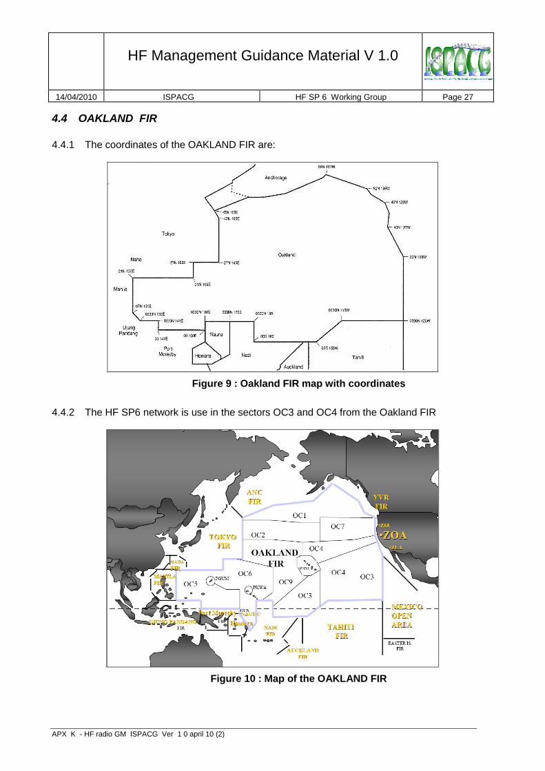
4.4 OAKLAND FIR
4.4.1 The coordinates of the OAKLAND FIR are:
Figure 9 : Oakland FIR map with coordinates
4.4.2 The HF SP6 network is use in the sectors OC3 and OC4 from the Oakland FIR
Figure 10 : Map of the OAKLAND FIR
HF Management Guidance Material V 1.0
14/04/2010 ISPACG HF SP 6 Working Group Page 28
APX K - HF radio GM ISPACG Ver 1 0 april 10 (2) Version 1.0 - 2003
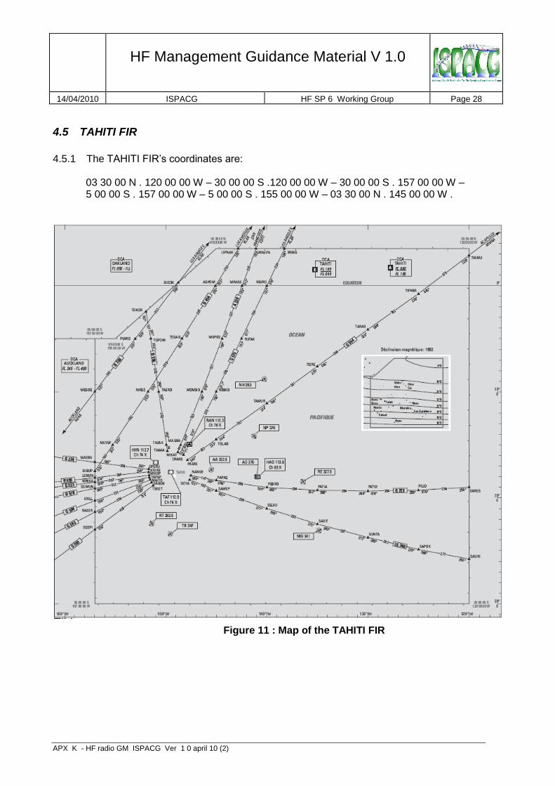
4.5 TAHITI FIR
4.5.1 The TAHITI FIR’s coordinates are:
03 30 00 N . 120 00 00 W – 30 00 00 S .120 00 00 W – 30 00 00 S . 157 00 00 W – 5 00 00 S . 157 00 00 W – 5 00 00 S . 155 00 00 W – 03 30 00 N . 145 00 00 W .
Figure 11 : Map of the TAHITI FIR

HF Management Guidance Material V 1.0
14/04/2010 ISPACG HF SP 6 Working Group Page 29
APX K - HF radio GM ISPACG Ver 1 0 april 10 (2) Version 1.0 - 2003
5 HF propagation prediction
5.1 AUSTRALIAN SPACE WEATHER AGENCY
5.1.1 The Australian Space Weather Agency provides in his Website : http://www.ips.gov.au predictions of HF propagation.
5.2 BRISBANE FIR
5.2.1 A special webpage was created for Airservices Australia:
http://www.ips.gov.au/Products_and_Services/5/1
5.3 AUCKLAND FIR
5.3.1 After reaching this webpage http://www.ips.gov.au/HF_Systems/1/1/1 select the city of Auckland to get the map of the propagation conditions in the FIR.
5.4 NADI FIR
5.4.1 From this webpage http://www.ips.gov.au/HF_Systems/1/1/1 select the city of Nadi to get
the map of the propagation conditions in the FIR.
5.5 OAKLAND FIR
5.5.1 The daily and hourly prediction of propagation are available on the IPS website :
http://www.ips.gov.au/Products_and_Services/5/12
5.6 TAHITI FIR
5.6.1 The IPS Web site provide for the FIR of Tahiti this link :
http://www.ips.gov.au/HF_Systems/1/1/2
5.6.2 Using theses informations the SEAC-PF has developped this website used by the ATC
controllers daily. http://pro.hilaire.org/hf/
login: prophf passwd: 2M3H0Z

HF Management Guidance Material V 1.0
14/04/2010 ISPACG HF SP 6 Working Group Page 30
APX K - HF radio GM ISPACG Ver 1 0 april 10 (2) Version 1.0 - 2003
6 General notes
6.1 Hours of service
6.1.1 Each station of the SP 6 network works 24/24 and 7/7.
6.2 Points of contact
6.2.1 Contact details of the station managers and watch supervisors for each radio station are
contained in the Annexes section as follows: Appendix B-1 (Brisbane), Appendix B-2 (Auckland), Appendix B-3 (Nadi), Appendix B-4 (San Francisco) and Appendix B-5 (Tahiti)
6.3 Coordination principles
6.3.1 For routine day-to-day operations such as inter-station tactical co-ordination of frequency assignments, network co-operation and support, etc., contact should be made with the duty supervisor/watch manager using the contact means specified in Appendixes B-1, 2, 3, 4 and 5.
6.3.2 When the coordination between stations involves subjects such as procedures, institutional
issues, or issues affecting the Network as a whole, etc., the contact to the station or stations should be made to the station manager through the points of contact defined in Appendixes B-1, 2, 3, 4 and 5.
6.4 Poor HF propagation conditions
6.4.1 Whenever a radio station duty supervisor/watch manager have access to information or warnings regarding poor HF propagation conditions or high levels of solar activities, that will affect the normal HF operations, he should notify the on duty Supervisor of the ATC unit in which the station provide the service.
6.5 HF operator
6.5.1 The FIR of Nadi, Brisbane, Auckland and Oakland use an Air Ground Operator. 6.5.2 In the FIR of Tahiti, the Air Traffic Controler is also the Air Ground Operator.

HF Management Guidance Material V 1.0
14/04/2010 ISPACG HF SP 6 Working Group Page 31
APX K - HF radio GM ISPACG Ver 1 0 april 10 (2) Version 1.0 - 2003
Appendices

HF Management Guidance Material V 1.0
14/04/2010 ISPACG HF SP 6 Working Group Page 32
APX K - HF radio GM ISPACG Ver 1 0 april 10 (2) Version 1.0 - 2003
Appendix A - HF medium characteristics
1.1 The term frequency is used to state the number of cycles occurring in one second, taking into
account that cycle means a complete oscillation of the alternating current. The distance travelled by a radio signal during the transmission of one cycle is called wavelength. Wavelength is inversely proportional to frequency, so that if frequency is increased the wavelength will decrease.
1.2 If an alternating current of suitably high frequency is fed to a transmitting aerial, the energy is
not confined to the metal of the aerial but radiates out into space in the form of electro-magnetic waves (radio waves). This radiation of energy through space comprises alternating and magnetic fields at right angles to each other.
1.3 As a general rule, radio signals travel in straight lines, that is, they follow great circle paths
over the surface of the earth. Under certain circumstances, however, the path of a signal may change direction, this change of direction is called refraction. Refraction examples are coastal, atmospheric and ionospheric, and the amount of refraction varies considerably, depending on certain conditions. Those conditions could be a change in direction when a signal crosses a coastline (coastal refraction), a change in direction due to a variation in temperature, pressure and humidity, particularly at low altitude (atmospheric refraction), or a change in direction when the radio wave passes through an ionised layer (ionospheric refraction).
1.4 The path of a radio wave from a transmitter to a receiver many miles away is not necessarily
direct, and in many cases, the signal may be reaching the receiver by more than one path at the same time. Because of the different path lengths there will be phase differences between the signals, and this fact will affect the resultant signal strength, phenomenon known as fading.
1.5 The main propagation paths between a transmitter and a receiver are, direct wave, ground-
reflected wave, space wave, surface wave, ground wave and sky wave. 1.5.1 When a signal travels in a straight line between the transmitter and receiver it is called
direct wave and its use is limited because of the earth curvature. If the radio wave arrive to the receiver after reflection at the earth’s surface it is called ground-reflected wave. These two waves are jointly known as the space wave and under normal conditions it’s the only propagation path for frequencies above 30 Mhz.
1.5.2 When a signal follows the curvature of the earth, this path is called surface wave, and is
normally caused by a phenomenon called diffraction. Diffraction occurs for all types of wave motion, and allows the wave to pass round earth obstacles and depends on the wavelength in relation to the radius of the earth. The range of surface wave depends on the wavelengths, with longer wavelengths (lower frequencies) the diffraction effect becomes more pronounced with consequently improved surface wave range, the type of surface, because different surfaces absorb different amounts of radio energy resulting in different rates of attenuation, being higher over land than over sea, and the frequency used, with lower frequencies suffering less attenuation along the surface and therefore providing better surface wave range.

HF Management Guidance Material V 1.0
14/04/2010 ISPACG HF SP 6 Working Group Page 33
APX K - HF radio GM ISPACG Ver 1 0 april 10 (2) Version 1.0 - 2003
1.5.3 The combination of direct, ground-reflected and surface waves can be described has the ground wave. However, not all of those types of waves have to be necessarily present together.
1.5.4 When signals are reflected or refracted down from ionised layers above the earth the path
is called sky waves, also sometimes called ionosphere waves.
1.6 Electron density Ultra-violet light from the sun can cause electrons to become separated from their parent atoms of the gases in the atmosphere. The atoms are left with resultant positive charges and are then known as ions. The intensity of the ionisation depends on the strength of the ultra-violet radiation and the density of the air.
Figure 12 : Electron density (El/m3)
The part of the atmosphere in which this process occurs is called the ionosphere, extending from about 50 Km to as high as 500 Km above the earth’s surface. When a radio wave enters such a layer, refraction occurs causing the wave to be bent away from its straight path. The amount of refraction depends on the frequency, the angle at which the wave enters the layer, and the intensity of ionisation.
1.7 The ionosphere is still under investigation but is known that several definite ionised layers
exist within it. During daytime hours there are four main ionisation layers designated D, E, F1 and F2 in ascending order of height. At night, when the sun’s radiation is absent, ionisation still persists but it is less intense, and fewer layers are found (D and F layers). Factors that affect the ionosphere layers is strength of the sun’s radiation, since it varies with latitude causing that the structure of the ionosphere varies widely over the earth’s surface, and the state of the sun, since sunspots affect the amount of ultra-violet radiation.

HF Management Guidance Material V 1.0
14/04/2010 ISPACG HF SP 6 Working Group Page 34
APX K - HF radio GM ISPACG Ver 1 0 april 10 (2) Version 1.0 - 2003
Figure 13 : Description of the Atmosphere
Figure 14 : Layers around the Earth
1.7.1 The D layer is only significant during daylight hours, dispersing soon after sunset. It is the
lowest layer and its intensity of ionisation is not great, in which VLF waves are reflected from the base of the layer, LF and MF waves enter the layer and are severely attenuated without being appreciably refracted, and higher frequency signals pass through the layer with less attenuation.
1.7.2 The E layer is strong ionised by day and remains weakly ionised by night, producing strong
sky waves in the LF and MF bands by night, but during the daytime due to the attenuation caused by the D layer the sky waves produced are too weak to used in these bands. Usable HF sky waves may be produced by this layer during nigh and day, and VHF signals usually pass through this layer, and if refraction exist it is insufficient to generate sky waves, unless under “freak” conditions, duct (or super-refraction) and scatter (or sporadic-E reflections) propagation. Ionospheric refraction is negligible with UHF, SHF and EHF signals and sky waves do not occur in these bands.
1.7.3 The F layer is the highest and more intensely ionised layer. At night there is only one F
layer, but during the daytime is divided into two layers, the F1 and F2. Strong sky waves are produced in the LF, MF and HF bands at night but only the HF band has usable F layer sky waves by day. Signals in the VHF and higher bands escape through the F layer into space with, normally, no sky waves produced.
1.8 Sky wave propagation in the HF band (3 to 30 MHz) is complicated, because there are many
variable factors, which decide whether or not there is a propagation path open between transmitter and receiver for long-range radiotelephony.

HF Management Guidance Material V 1.0
14/04/2010 ISPACG HF SP 6 Working Group Page 35
APX K - HF radio GM ISPACG Ver 1 0 april 10 (2) Version 1.0 - 2003
1.8.1 For a given frequency and state of the ionosphere, the amount of refractive “bending” of the wave will depend on the angle at which the wave penetrates the layer. Waves travelling nearly vertically may escape through a layer, but may be returned to earth if a higher more intensely ionised layer exists.
Figure 15 : Critical angle (HF band)
1.8.2 As can be seen on Figure 15, waves ascending with an increased angle with the vertical,
the amount of bending is greater and when the angle with the vertical is increased to the critical angle, the path is bent enough for the wave to return to earth as the first sky wave. Waves making an angle with the vertical greater than the critical angle will also produce sky waves, coming down to earth at greater ranges than that of the first sky wave. The range from the transmitter and the first sky wave for a given frequency and set of conditions is called the skip distance. If the surface wave from a HF transmitter become completely attenuated at a shorter range than that at which the first sky wave returns to earth, leaves an area in which neither ground wave nor sky waves are received and which is none as dead space (Figure 16).
Figure 16 : Dead space (HF band)

HF Management Guidance Material V 1.0
14/04/2010 ISPACG HF SP 6 Working Group Page 36
APX K - HF radio GM ISPACG Ver 1 0 april 10 (2) Version 1.0 - 2003
1.8.3 Critical angle depends largely on the frequency, the higher the frequency the greater the critical angle, therefore, if skip distance is to be reduced, a lower frequency has to be used. This is most significant when choosing the optimum frequencies for HF communications and ensuring that the skip distance is less than the range of the distant receiver.
1.8.4 For good long-range HF R/T reception a frequency must be chosen which will not suffer too
much attenuation. If a relatively high frequency is used, for example 29 MHz, most of the energy will pass through the E layer and be reflected from the more intensely ionised F layer. The higher the frequency, the greater degree of ionisation is required to give reflection. As frequency is reduced and attenuation of the E layer reflections increases, a limit is reached called the “Lowest Usable Frequency (LUF)”, and bellow this frequency the attenuation is too great for the signal to be usable.
1.8.5 Thus for least attenuation, and so the highest received signal strength for a given
transmitter power, a frequency is chosen which is as high as possible without exceeding the MUF (Maximum Usable Frequency) for the path between the transmitter and distant receiver. The MUF is that frequency, for the prevailing conditions, which produces a skip zone extending just short of the distant receiver. Any higher frequency would give a higher critical angle and a greater skip distance exceeding beyond the receiver, which would then loose that sky wave contact with the transmitter.
1.8.6 MUF at night is much less than by day, because the intensity of ionisation in the layer is
less so than lower frequencies have to be used to produce the same amount of refractive bending and give the same critical angle and skip distance as by day. However, the signal attenuation in the ionosphere in the ionosphere is also much less at night so the lower frequency needed is still usable. Hence the night frequency for a given path is about half of the day frequency, and shorter distances can be worked at night than by day while still using a single reflection from the F layer.
1.8.7 The MUF not only varies with path length and between day and night, but also with season,
meteor trails, sunspot state, and sudden ionospheric disturbances produced by eruptions on the sun. Because of the variations of MUF, HF transmitting stations have to use frequencies varying widely between about 2 and 20 MHz.
1.9 The theoretical range for HF frequencies varies, depending on the propagation path used,
ground or sky waves. Ground waves usually can reach up to 100 nm and sky waves longer distances, however, sky waves will not be received within the skip distance (probably several hundred miles from the transmitter). The theoretical maximum range obtained by means of a single reflection from the E layer is about 1 300 nm, and from the F layer about 2 500 nm. This theoretical maximum range is achieved with the transmitted signal leaving the earth’s surface tangentially. Ranges of 8 000 nm or more may be achieved by means of multiple reflections, mainly from the F layer, being the signal alternately refracted down from the layer and reflected up again from the earth’s surface until it becomes too weak to use.

APX K - HF radio GM ISPACG Ver 1 0 april 10 (2)
Appendix B-1 - Brisbane Radio Station Information
Station Name: Brisbane Radio
Country: Australia State: Queensland
City: Brisbane Geographic Location: S27.23.0 E153.07.1 AFTN Address: YBBBYINTL Aircraft in Flight Address: YBBB
SATCOM SHORT CODE Nr. : 450 302
Facilities Transmitter site(s) Receiver site(s)
Location and equipment: Location and equipment: Cape Pallarenda (Townsville) – 19.12.05.8S 146.46.05.3E 4 X Cubic T-4180/COM1000 1kW HF transmitters, comprising 2 X SP6 & 2 X SEA3 2 X Andrew Model 3005 Triple Mode Low Profile Spira-Cone HF antenna
Broken Hill – 31.55.38.7S 141.28.57.4E
2 X Cubic T-4180/COM1000 1kW HF transmitters, comprising 2 X SP6
2 X Andrew Model 3005 Triple Mode Low Profile Spira-Cone HF antenna Knuckeys Lagoon (Darwin) – 12.25.52.0S 130.57.51.5E 2 X Cubic T-4180/COM1000 1kW HF transmitters, comprising 2 X SEA3 2 X Andrew Model 3005 Triple Mode Low Profile Spira-Cone HF antenna
Cape Clevedon (Townsville) – 19.21.03.8S 147.01.06.5E
18 X Cubic LCR-2000 HF receivers, comprising 9 X SP6 & 9 X SEA3
1 X Andrew Model 3005 Dual Mode Low Profile Spira-Cone HF antenna
Broken Hill – 32.00.22.4S 141.28.26.1E
9 X Cubic LCR-2000 HF receivers, comprising 9 X SP6
1 X Andrew Model 3005 Dual Low Profile Spira-Cone HF antenna
Shoal Bay (Darwin) – 12.22.49.5S 130.58.26.2E
9 X Cubic LCR-2000 HF receivers, comprising 9 X SEA3
1 X Andrew Model 3005 Dual Low Profile Spira-Cone HF antenna
Class of Emission: J3E SELCAL: selcal-coder
Frequencies
Family Frequency bands 3 MHz 3.5 MHz 4 MHz 5 MHz 6 MHz 8 MHz 11 MHz 13 MHz 17 MHz
SP6 3.467 5.643 8.867 13.261 17.904
SEA-3 3.470 6.556 11.396 13.318 17.907
Volmet 6.676 11.387

APX K - HF radio GM ISPACG Ver 1 0 april 10 (2)
Station Manager * Supervisor
Name: Mr Ian Harding Name: Duty Operations Supervisor
Post Address: Locked Bag 747 Eagle Farm Brisbane Australia 4009
Post Address: The Australian Flight Information Centre Locked Bag 747 Eagle Farm Brisbane Australia 4009
Phone: + 61 7 38663544 Phone: + 61 7 38663429 Fax: + 61 7 38663742 Fax: + 61 7 38663553 Email: ian.harding @airservicesaustralia.com Email: [email protected]
Remarks: Brisbane Radio also provides international HF communications for Australian Air Traffic Control within the contracted airspace of the Honiara and Naru FIR’s Brisbane Radio provides communication services from Perth and Port Hedland sites that cover the INO-1 MWARA

APX K - HF radio GM ISPACG Ver 1 0 april 10 (2)
Appendix B-2 - Auckland Radio Station Information
Station Name: Auckland Radio
Country: New Zealand State
City: Auckland Geog. Location: 370017S1744849E AFTN Address: NZAAYSYX Aircraft in Flight Address: NZZO
SATCOM SHORT CODE Nr. : 451 201
Facilities
Transmitter site Receiver site
Location: Wiroa Island Location: Seagrove
Equipment Equipment Transmitters 8 x Marconi ST-5000/NZ 5 KW HF Transmitters comprising 2 x Air Ground 3 x VOLMET 1 x METFAX 1 x Air New Zealand 1 x Spare Aerials 5 x Civil Aviation (NZ) RM 88 Wideband 2–30 MHz 1 x Marconi R7070 wideband 2–30 MHz (Air New Zealand only) 4 x Marconi R7080 wideband 2-30 MHz
Receivers 16 x Eddystone 6100 HF receivers comprising:- 5 x MWARA 3 x ODF 2 x Spare 6 x OCC (Air New Zealand only) 2 x Eddystone 1771 receiver remote controllers Aerials 3 x Civil Aviation (NZ) RM 88 Wideband 2–30 MHz 1 x Creative Design sector coverage log-periodic dipole antenna Type 230HF-2D (Air New Zealand only)
Class of Emission: USB/AM SELCAL:
Frequencies
Family Frequency bands
3 MHz 3.5
MHz 4.7
MHz 5.6
MHz 6.6
MHz 9 MHz
11.3 MHz
13.3 MHz
18 MHz
A 3467 5643 8867 13261 17904
LDOCC 3007 6637 10072 1333 17940
SAR
VOLMET 6679 8828 13282

APX K - HF radio GM ISPACG Ver 1 0 april 10 (2)
Station Manager On Duty Supervisor
Name: Mark Goodall Post Address: Airways New Zealand Limited. Fred Ladd Way. Auckland International Airport.
Post Address: Airways New Zealand Limited. Fred Ladd Way. Auckland International Airport.
Phone: + 64 9 2753109 Phone: + 64 9 2568071 Fax: + 64 9 2753106 Fax: + 64 9 2753627 Email: [email protected] Email: [email protected] AFTN/SITA Address: NZZOZQZF AFTN/SITA Address: NZAAYSYX
Remarks: By international agreement Auckland Radio provides communications services for the Auckland OCA. The associated OACC is located at Auckland, New Zealand.

APX K - HF radio GM ISPACG Ver 1 0 april 10 (2)
Appendix B-3 - Nadi Radio Station Information
Station Name: Nadi Radio
Country: Fiji State
City: Nadi Geog. Location: 17° 45′ 19″ S, 177° 26′ 36″ E
AFTN Address: NFFNYFYX Aircraft in Flight Address: NFFNZZZX
SATCOM SHORT CODE Nr. : + 679 6724174
Facilities
Transmitter site Receiver site
Location: Enamanu Transmission station Location: Nadi Airport
Equipment ( see below) Equipment ( see below) Transmitters JRC JRS-714 10 KW x4 JRC JRS-753 5 KW x2 JRC JRS-752 500 W x2 Antenna Patch §unit NKZ – 93 x1 Modems : NHH 62 modems frames x2 CNM 199 TV x6 Aerials Conifans – 600 Ohms 2-30 MHz x1 Mono pole – 75 Ohms 2-30 MHz x1 Marconipoles – 50 Ohms 2-30 MHz x5 VoiceSwitch: GAREX VCSS 220
Receivers : JRC NRD 840A All wave receiver x 36 JRC NRD 302A Tunable receiver x 9 Antenna Multicoupleurs NAJ -110B x3 Receiver Controller Unit NJC-536B x8 Modems NMC – 207 x16 Antenna System: TFD – Terminated folded dipole x3 2-30 Mhz Range
Class of Emission: J3E SELCAL: Baumberger Electronics BEW 783 -200 X 3 units

APX K - HF radio GM ISPACG Ver 1 0 april 10 (2)
Frequencies
Family Frequency bands
3 MHz 3.5
MHz 4.7
MHz 5.6
MHz 6.6
MHz 9 MHz
11.3 MHz
13.3 MHz
18 MHz
A 3467 5643 8867 13261 17904
RDARA 3425 8846 11339
SAR 3023 5680
Station Manager On Duty Supervisor
Name: MR Vula SERU Post Address: Airport Fiji Limited. Private Mail Bag. Nadi Airport. Fiji
Post Address: . Airport Fiji Limited. Private Mail Bag. Nadi Airport. Fiji Phone: + 679 6725777 Ext 4514 Phone: Fax: + 679 6725161 Fax: Email: [email protected] Email AFTN/SITA Address: NANCDYA AFTN/SITA Address:
Remarks:.

APX K - HF radio GM ISPACG Ver 1 0 april 10 (2)
Appendix B-4 - San Francisco Radio Station Information
Station Name: SAN FRANCISCO Radio Station Information
Country: United States of America State: California
City: Livermore Geographic Location: 37.70 N 121.72 W AFTN Address: KSFOXAAG Aircraft in Flight Address: KSFOZZZX
SATCOM SHORT CODE Nr. : 436625
Facilities Transmitter site See below Receiver site See below

APX K - HF radio GM ISPACG Ver 1 0 april 10 (2)
Transmitters Dixon (38. 22.46.7 N 121.45. 50.9 W) (D) 2 TCI 532-N Log-Periodic (3-30 MHz) 2 TCI 530 log-periodic OMNI (3-30 MHz) 4 AERCOM 1330 (5KW) 1 Cubic CTX-1000 (1KW) standby Moloka’i, Hawaii (21.10.33.5N 157.10.38.9 W) (M) 3 TCI 527-B Log-Periodic (6.2-30 MHz) -NP2 Direction: 346 deg., 6.2-30 MHz -NP3 Direction: 346 deg., 6.2-30 MHz 2 TCI 527-3-28 Log-periodic (6.2-30 MHz) -CWP2 275 deg., 6.2-30 MHz -CWP1 183.5 deg., 6.2-30 MHz 3 TCI 532-4-28 Log-Periodic. (3-30 MHz) -CEP Direction: N - 51 deg., 3-30 MHz -CEP Direction: S - 57 deg., 3-30 MHz -SP Direction: 188 deg., 3-30 MHz 2 TCI 530-4-28 Log-Periodic OMNI (3-30 MHz) 7 CUBIC CTX-5000 (5KW) Standby transmitter 1 Cubic CTX-5000 (5KW) Oahu, Hawaii (21.22.30.6 N 158.5.5.1 W) Auxiliary transceiver 1 TCI 530 Log-Periodic (3-30 MHz) 1 Cubic CTX-1000 (1KW) Barrow, Alaska (71.15.30.9 N 156. 34.38.9 W (B) 1 TCI 530 Omni (3-30 MHz) 1 CTX-1000 (1KW) Mt. Barragada, Guam 13.19.17 N 144.49.30 E 1 Fan Dipole Antenna 7 TenTec transmitters Hat Yai, Thailand 06.56.10.84N 100.23.18.12E Antenna 06.56.12.79N100.23.19.41E 1 TCI 530-05 (2.8-30MHz) 1 Cubic TCX 1000
Receivers Half Moon Bay (37.39. 00 N 122. 41. 00 W) 2 TCI 532-B log-periodic (3-30 MHz) -North Direction W 278 degrees -West Direction SW 222 degrees 1 TCI 530 log-periodic OMNI (3-30 MHz) 1 TCI 527B log-periodic (3-30 MHz) -Direction S – 135 degrees 5 TenTec RX331 (CEP2) 14 TenTec RX330 Moloka’i, Hawaii (21.12.23 N 157.12.30 W) 1 TCI 532-4 Log-Periodic (3-30 MHz) -CEP Direction: 051 deg. 1 TCI 527-3 Log-Periodic (6.2-30 MHz) -WP Direction: 283.5 deg. 2 TCI 527-B Log-Periodic (6.2-30 MHz) NP Direction: 346 deg. SP Direction: 188 deg. 38 LCR-2000 Moloka’I standby receiver 7 Cubic LCR-2000 Oahu, Hawaii 21.22.30.6 N 158.5.5.1 W Oahu Auxiliary transceivers 7 TenTec RX330B Barrow, Alaska 71.15.30.9 N 156.34.38.9 W TCI 530-6 7 Cubic LCR-2000 Pulantat, Guam 13.25.00 N 144.44.47 E 1 HF Braodband dipole (2 MHz-30 MHz) TCI-535 (3-30 MHz) 1 TCI Conical Monopole Antenna (LDOC) 4 CDR-3250 6 TenTec RX331 (LDOCF) 7 TenTec RX331 (CWP) Hat Yai, Thailand 06.56.24.71N 100.24.47.28E Antenna 06.56.25.03N 100.24.49.84E TCI 530-05 (2.8-30MHz) 7 Cubic LCR 2000 1 Cubic LCR 2000 (Spare)
Class of Emission: 1K40H2B/2K80J3E SELCAL: 17 FREQUENTIS Units

APX K - HF radio GM ISPACG Ver 1 0 april 10 (2)
Frequencies
Family
Frequency bands
2-3 MHz
4 MHz 5 MHz 6 MHz 8 MHz 10-11 MHz
13 MHz 17 MHz 21 MHz
(D)CEP1 3413 5574 8843 13354
(D)CEP2 2869 5547 11282 13288 21964
(D)CEP3 3452 6673 10057 13288
(M) SP 3467 5643 8867 13261 17904
(M)CWP1 2998 / 3455
4666 6532 11384 13300 17904
(M)CWP2 2998 5652 6532 8903 11384 17904 21985
Guam CWP 2998 / 3455
4666 5652 6532 8903 11384
(M) NP1 5628 6655 8915 10048 13339 17946 21925
(M) NP2 2932 5667 6655 8951 11330 13273 17946
(B) NP 5628 6655 8915 10048 13339 17946 21925
(M) CEP1 3413 5574 8843 13354
(M) CEP2 2869 5547 8867 11282 13288
(M) SP 3467 5643 8867 13261 17904
(G/M/D/B)
LDOCF 3494 6640 8933 11342 13348 17925 21964
(HDY) LDOCF
3494 6640 11342 13348 17925 21964
Station Operations Manager: On Duty Manager: Andrew Colombana, Robin Lee, Lynn Sallady, Leigh-Lu Prasse or Swami Nand (Shift Managers)
Name: Tammy J. Callahan Post Address: 6011 Industrial Way Livermore, California, USA 94550
Post Address: 6011 Industrial Way Livermore, California, USA 94550
Phone: + 1 925-519-0792 Phone: + 1 800-799-7847
Fax: + 1 925-294-9597 Fax: + 1 925-294-9597
Email: [email protected] Email: [email protected]
AFTN/SITA Address: KSFOTCXA AFTN/SITA Address: KSFOSMXA
Remarks: : PHNL-PMKK VHF 131.95 (HA) PGUM VHF 191.95 (GA)

APX K - HF radio GM ISPACG Ver 1 0 april 10 (2)
Appendix B-5 - TAHITI Control Station Information
Station Name: TAHITI Control
Country: France State: French Polynesia
City: FAAA Geographic Location: 17° 33 20S 148° 36 60W
AFTN Address: NTTTZQZX Aircraft in Flight Address: NTTTZZZX
SATCOM SHORT CODE Nr. : 42 27 90
Facilities Transmitter site Receiver site
Location: FAAA
(17° 33 20S 148° 36 60W)
Location: FAAA (LA HUNA)
(17° 33 20S 148° 36 60W) Equipment Equipment Antennas 2 Biconics (Fuseau) 1 Spiracone Andrew 3002 Transmitters 2* Nardeux T166 1KW Backup station: Antennas 1 Volubilis 1 Hormi ( THX ) 1 Spiracone Andrew 3002 Transmitters
1 * Rhode &Schwarz XK 2900 1 KW
20 I2E receivers 1 Biconic antenna BCI3-30 1 Spiracone Andrew 3002 ( 1 low angle (long-medium range)) ( 1 high angle (short- range)) Backup station 6 * I2E receivers 1 * ASD 2-30 semi delta
Class of Emission: 2K80J3E / SELCAL: 5 DANKS RADIO SC9100
Frequencies
Family Frequency bands 3 MHz 3.5 MHz 4.7 MHz 5.6 MHz 6.6 MHz 9 MHz 11.3 MHz 13.3 MHz 18 MHz
SP 3467 5643 8867 13261 17904
9C(project)
Fix 5066.5 6801 9116 12166.5
SAR 5680

APX K - HF radio GM ISPACG Ver 1 0 april 10 (2)
Station Manager On Duty Supervisor
Name: Eric LIEUTAUD Post Address: Service Navigation Aerienne Division technique BP 6011 FAAA 98702 FAAA TAHITI – French Polynesia
Post Address: Service Navigation Aerienne Division technique BP 6011 FAAA 98702 FAAA TAHITI – French Polynesia Phone: + 689 86 10 30 Phone: + 689 86 11 33 Fax: + 689 86 10 39 Fax: + 689 86 10 39 Email: [email protected] Email: [email protected] AFTN/SITA Address: NTAA AFTN/SITA Address: NTAAYSYX
Remarks: TAHITI radio is collocated and is a department within TAHITI OACC
Backup receiver site is also located in the vicinity of TAHITI OACC

APX K - HF radio GM ISPACG Ver 1 0 april 10 (2)
LIST OF FIGURES
Figure 1 : MWARA – SP (Ref. ITU Appendix 27 Aer2) .................................................................. 17 Figure 2 : RDARA Map - South Pacific ( Appendix S27 ITU RR) .................................................. 19 Figure 3 : Australian RDARA network ........................................................................................... 20 Figure 4 : Sectors in the NZZO FIR ............................................................................................... 21 Figure 5 : Map of Australian's FIR ................................................................................................. 24 Figure 6 : Map of Australia - HF Frequencies Areas ...................................................................... 25 Figure 7 : map of the Auckland Oceancic FIR ............................................................................... 25 Figure 8 : Map of the NADI FIR ..................................................................................................... 26 Figure 9 : Oakland FIR map with coordinates ............................................................................... 27 Figure 10 : Map of the OAKLAND FIR .......................................................................................... 27 Figure 11 : Map of the TAHITI FIR ................................................................................................ 28 Figure 12 : Electron density (El/m3) ............................................................................................... 33 Figure 13 : Description of the Atmosphere .................................................................................... 34 Figure 14 : Layers around the Earth .............................................................................................. 34 Figure 15 : Critical angle (HF band) .............................................................................................. 35 Figure 16 : Dead space (HF band) ................................................................................................ 35
LIST OF TABLES
Table 1: Frequency band usage (ref. ITU Appendix 27 Aer2) ....................................................... 13 Table 2 : Frequency bands of the MWARA – SP (Ref. ITU Appendix 27 Aer2) ........................... 18 Table 3 : HF Frequencies SP6 NETWORK ( in KHz) ................................................................... 18 Table 4 : General principes for frequency assigment .................................................................... 23 Table 5 : Nadi FIR coordinates ...................................................................................................... 26

APX K - HF radio GM ISPACG Ver 1 0 april 10 (2)
---- END of Document ---