interlocking pavement
TRANSCRIPT

INTERLOCKING PAVEMENT
1
2
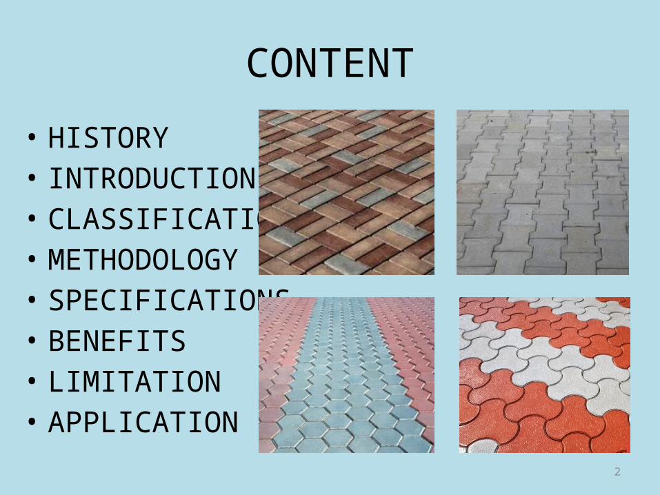
CONTENT
• HISTORY• INTRODUCTION• CLASSIFICATION• METHODOLOGY• SPECIFICATIONS• BENEFITS• LIMITATION• APPLICATION

3
HISTORY• An early version of interlocking concrete pavement dates back
to the Roman Empire when The Appian Way was built from stone paving on an aggregate base in 312 B.C.
• Used as a main route for military supplies, it connected Rome to Brindisi, Apulia, in southeast Italy.• The road is 350 miles long about 20 feet wide and has held up for more than 2,000 years.
Figure 1: The Appian Way
4
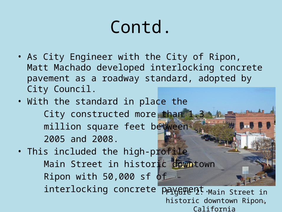
Contd.• As City Engineer with the City of Ripon, Matt Machado
developed interlocking concrete pavement as a roadway standard, adopted by City Council.
• With the standard in place the City constructed more than 1.3 million square feet between 2005 and 2008.• This included the high-profile Main Street in historic downtown Ripon with 50,000 sf of interlocking concrete pavement.
Figure 2: Main Street in historic downtown Ripon, California
5
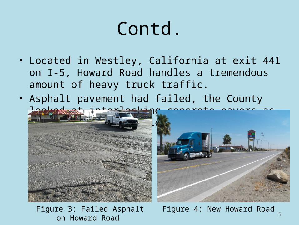
Contd.• Located in Westley, California at exit 441 on I-5, Howard Road
handles a tremendous amount of heavy truck traffic.• Asphalt pavement had failed, the County looked at
interlocking concrete pavers as the innovative solution.
Figure 3: Failed Asphalt on Howard Road
Figure 4: New Howard Road
6
INTRODUCTION• Permeable interlocking concrete pavement, also referred to
as PICP, consists solid concrete paving units called ‘pavers’ with joints that create openings in the pavement surface when assembled into a pattern.
• The joints are filled with permeable aggregates that allow water to freely enter the surface.
• The permeable surface allows flow rates as high as 1,000 in./hr (2,540 cm/hr).
• The paving units are placed on a bedding layer of permeable aggregates which rests over a base and subbase of open-graded aggregates.

7
Contd.• The base and subbase store water and allow it to infiltrate
into the soil subgrade.
• Perforated underdrains in the base or subbase are used to remove water that does not infiltrate within a given design period, typically 48 to 72 hours.
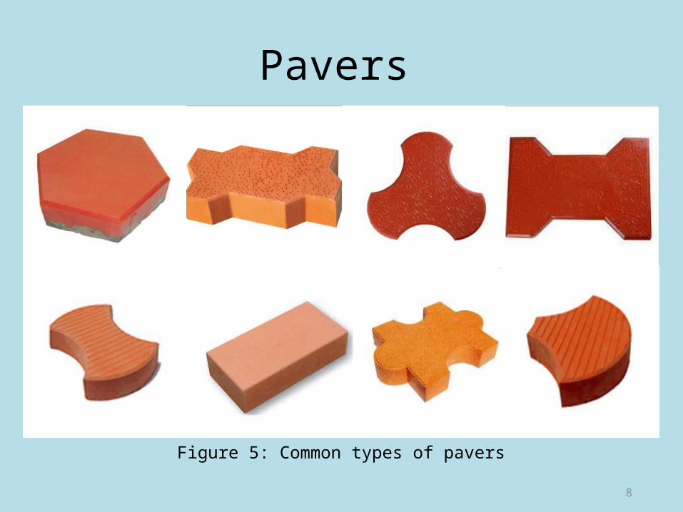
Pavers
8
Figure 5: Common types of pavers

9Figure 6: Cross-section of interlocking pavement
10
Classification• A partial infiltration design is providing drainage to
accommodate some water that does on enter low infiltration soils.
• PICP over high infiltration subgrade soils may not require an underdrain(s) and these are called are called full infiltration designs.
• The use of a geo-membrane to restrict infiltration into the soil subgrade is often called a no infiltration design.

11
METHODOLOGY
Design
• Consideration is given to hydrologic design for storm water management and to structural design to support anticipated vehicle axle loads.
• The thicker of the two bases from structural and hydrologic designs is selected.
12
Pre-construction meeting • Walk through the site with builder/contractor/ subcontractor
to review erosion and sediment control plan/storm water pollution prevention plan.
• Determine when PICP is built in project construction sequence and confirm specified measures for PICP protection and surface cleaning
• Aggregate material storage locations identified (hard surface or on geotextile)
• Sediment management • Access routes for delivery and construction vehicles identified

13
Excavation• Utilities located and marked by local service • Excavated area marked with paint and/or stakes • Excavation size and location conforms to plan • The stakes should be marked to establish grades, or have string lines pulled and tied to them. • Slopes should be a minimum of 1.5%.• Protect temporary soil stockpiles from erosion from water and wind
Figure 7: Excavation of the soil subgrade.

14
Soil Subgrade• Rocks and roots removed, voids refilled with open-graded
aggregate • Soil compacted to specifications and field tested with density
measurements per specifications • No groundwater seepage or standing water • Low, wet areas can be stabilized with a layer of crushed stone.• The surface of the stone is even with the top of the compacted soil subgrade.
Figure 8: Compacting the soil subgrade.
15
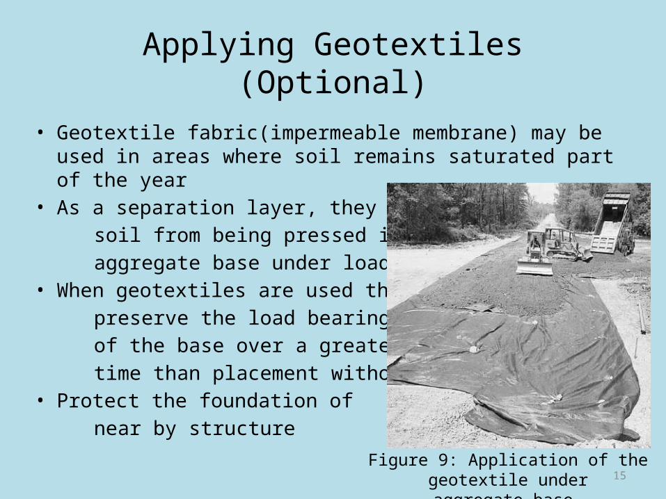
Applying Geotextiles (Optional)• Geotextile fabric(impermeable membrane) may be used in
areas where soil remains saturated part of the year• As a separation layer, they prevent soil from being pressed into the aggregate base under loads• When geotextiles are used they preserve the load bearing capacity of the base over a greater length of time than placement without them• Protect the foundation of near by structure
Figure 9: Application of the geotextile underaggregate base.
16
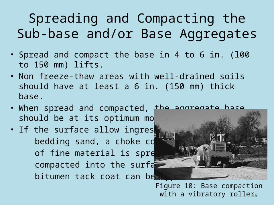
Spreading and Compacting the Sub-base and/or Base Aggregates
• Spread and compact the base in 4 to 6 in. (l00 to 150 mm) lifts.• Non freeze-thaw areas with well-drained soils should have at
least a 6 in. (150 mm) thick base.• When spread and compacted, the aggregate base should be at
its optimum moisture.• If the surface allow ingress of bedding sand, a choke course of fine material is spread and compacted into the surface, or a bitumen tack coat can be applied.
Figure 10: Base compaction with a vibratory roller.

17
Placing and Screedingthe Bedding Sand
• Masonry sand for mortar should never be used for bedding, nor should limestone screenings or stone dust.
• The bedding sand should have symmetrical particles, generally sharp, washed, with no foreign material.
• Bedding sand should be spread and screeded to a nominal 1 in. (25 mm) thickness• The sand is screeded with a true strike board.
Figure 11: Screeding the bedding sand.
18
Placing the Concrete Pavers• Concrete pavers can be placed in many patterns.• Joint widths between the pavers should be consistent and be
between 1/16 and 3/16 in. (2 and 5 mm).• Cut pavers should be used to fill gaps along the edge of the
pavement. Pavers are cut with a double bladed splitter.• After an area of pavers is placed, it should be compacted with
a vibrating plate compactor• Dry joint sand is swept into the joints and the pavers
compacted again until the joints are full.• Excess sand is then removed.• A small amount of settling is typical of all flexible pavements.• Optional sealers or joint sand stabilizers may be applied.

19
Figure 12: Placing the concrete pavers.
Figure 13: Saw cutting pavers.
Figure 14: Excess sand swept from the finished surface
Figure 15: Compacting Figure 16: Spreading and sweeping joint sand.
Figure 17: Vibrating sand into the joints.
20
Specifications• Foundation Walls: At least 10 ft (3 m) from foundations with
no waterproofing or drainage • Water Supply: At least 100 ft (30 m) from municipal water
supply wells • Concrete sand conforming to CSA A23.1 is recommended - it's
the same sand mixed into concrete pavers and poured, cast-in-place concrete.
• The ICPI only recommends the use of base material meeting gradation requirements of ASTM-D2940 with 6 to 12% passing the no. 200 (80 micron) sieve.
21
Contd.• ICPI recommends a minimum base thickness of 4 inches (100
mm) for residential patios and walkways and 6 inches (150 mm) for driveways in non freeze thaw areas.
• In colder climates these base thicknesses are increased and most contractors will use 6 and 10 inches (150 mm and 250 mm) respectively.
• For non-vehicular uses such as embankment stabilization, the maximum slope is determined by the angle of repose of the bedding sand, typically around 35 to 38 degrees.
• For vehicular traffic, the highest slope in use is about 10 degrees.
22
What are the benefits of concrete pavers?
• Concrete pavers do not crack like asphalt or poured-in-place concrete - each unit has joints that allow for a small amount of movement without cracking.
• Concrete pavers are easy to repair and/or replace, especially when repairs are being done to the base or underground utilities. Asphalt, concrete, and stamped concrete can't make this claim.
• Resists deterioration from freeze-thaw cycles.

23
• Concrete pavers come in many shapes and colours.
• Paving stones should last over 30 years, which is much longer than alternative pavements under normal residential use.
• Capable of wet weather (light rain) installation
• Immediately ready for traffic upon completion, no time needed for curing
• Upto 100% infiltration depending on the design

24
LIMITATION• PICP should not be used in areas subject to loading/unloading
or storage of hazardous materials.
• It is generally not placed in areas with high depth to seasonal water tables.
• It should not be used in very cold areas, where temperature drops below freezing point of water.
• When load is eccentric pavers may come out or shift from their position.

25
ApplicationPICP is used for:
• Walkways• Driveways• Parking lots• Alleys• Low-speed roads• Road shoulders etc.

26