interference management for femtocell networks
TRANSCRIPT
The Pennsylvania State University
The Graduate School
Department of Electrical Engineering
INTERFERENCE MANAGEMENT FOR FEMTOCELL
NETWORKS
A Thesis in
Electrical Engineering
by
Basak Guler
c⃝ 2012 Basak Guler
Submitted in Partial Fulfillmentof the Requirementsfor the Degree of
Master of Science
May 2012

The thesis of Basak Guler was reviewed and approved* by the following:
Aylin YenerProfessor of Electrical EngineeringThesis Adviser
Vishal MongaAssistant Professor of Electrical Engineering
Kultegin AydinProfessor of Electrical Engineering
*Signatures are on file in the Graduate School.

iii
Abstract
This thesis proposes methods for applying the idea of Interference Alignment (IA)
in femtocell networks. In the first method, in order to manage the uplink interference
caused by macrocell users (MU) at the femtocell base stations (FBS), cooperation be-
tween macrocell users with the closest femtocell base stations is used to align the received
signals of macrocell users in the same subspace at multiple FBSs simultaneously. The
proposed method achieves IA while providing the QoS requirements of macrocell users,
in terms of minimum received SINR at the macrocell base station (MBS). With this ap-
proach, the BER performance of femtocell users is shown to improve, while maintaining
the quality of the communication channel of macrocell users. In the second method,
an interference limited multi-tier multiuser MIMO cellular uplink is considered. Specif-
ically, an interference management scheme is proposed where interference from subsets
of macrocell users is aligned at the femtocell base stations in order to ensure acceptable
service for the femtocell users. The scheme employs interference alignment at each fem-
tocell base station, to the set of macrocell users that are causing the high interference
specifically at that FBS, and is termed selective IA. The proposed IA algorithm deter-
mines the interference subspaces at each FBS and precoders for each macrocell user in
a distributed fashion.
iv
Table of Contents
List of Figures . . . . . . . . . . . . . . . . . . . . . . . . . . . . . . . . . . . . . vi
Acknowledgments . . . . . . . . . . . . . . . . . . . . . . . . . . . . . . . . . . . viii
Chapter 1. Introduction . . . . . . . . . . . . . . . . . . . . . . . . . . . . . . . . 1
Chapter 2. Background . . . . . . . . . . . . . . . . . . . . . . . . . . . . . . . . 6
2.1 Femtocells: Home Base Stations . . . . . . . . . . . . . . . . . . . . . 7
2.2 Interference Alignment . . . . . . . . . . . . . . . . . . . . . . . . . . 11
2.2.1 Minimum Leakage Interference IA . . . . . . . . . . . . . . . 18
2.2.2 Max SINR . . . . . . . . . . . . . . . . . . . . . . . . . . . . . 19
2.2.3 Alternating Minimization . . . . . . . . . . . . . . . . . . . . 20
2.2.4 Minimum Mean Squared Error IA . . . . . . . . . . . . . . . 22
2.2.5 Least Squares Approach for IA . . . . . . . . . . . . . . . . . 22
Chapter 3. Interference Alignment for Cooperative MIMO Femtocell Networks . 25
3.1 Introduction . . . . . . . . . . . . . . . . . . . . . . . . . . . . . . . . 25
3.2 System Model . . . . . . . . . . . . . . . . . . . . . . . . . . . . . . . 26
3.3 Interference Alignment with Successive SDP Relaxations . . . . . . . 28
3.4 Minimum sum MSE with Coordinated Zero-Forcing . . . . . . . . . 32
3.5 Minimum sum MSE without Zero Forcing . . . . . . . . . . . . . . . 35
3.6 Simulation Results . . . . . . . . . . . . . . . . . . . . . . . . . . . . 37

v
Chapter 4. Distributed Multiuser MIMO Interference Alignment . . . . . . . . . 41
4.1 Introduction . . . . . . . . . . . . . . . . . . . . . . . . . . . . . . . . 41
4.2 Distributed Interference Alignment for the K-user Interference Channel 42
4.3 Distributed Interference Alignment with Imperfect Channel Information 52
4.4 Distributed Interference Alignment for Tiered Networks . . . . . . . 58
Chapter 5. Selective Interference Alignment for MIMO Femtocell Networks . . . 68
5.1 Introduction . . . . . . . . . . . . . . . . . . . . . . . . . . . . . . . . 68
5.2 System Model . . . . . . . . . . . . . . . . . . . . . . . . . . . . . . . 71
5.3 Macrocell User Selection for Interference Alignment . . . . . . . . . . 73
5.4 Selective Distributed Interference Alignment for Tiered Networks . . 75
5.5 Convergence Analysis and Discussion . . . . . . . . . . . . . . . . . . 80
5.6 Simulation Results . . . . . . . . . . . . . . . . . . . . . . . . . . . . 82
Chapter 6. Conclusion . . . . . . . . . . . . . . . . . . . . . . . . . . . . . . . . . 85

vi
List of Figures
2.1 A basic femtocell network . . . . . . . . . . . . . . . . . . . . . . . . . . 8
2.2 Comparison of coverage areas of various cell sizes . . . . . . . . . . . . . 9
2.3 Spectrum access for femtocells . . . . . . . . . . . . . . . . . . . . . . . 10
2.4 Sources of Interference for a Tiered Network . . . . . . . . . . . . . . . . 12
2.5 Dominant macrocell interferer . . . . . . . . . . . . . . . . . . . . . . . . 13
2.6 K user interference channel . . . . . . . . . . . . . . . . . . . . . . . . . 14
2.7 Interference Alignment in a 3 user interference channel . . . . . . . . . . 15
2.8 Alternating Minimization . . . . . . . . . . . . . . . . . . . . . . . . . . 21
3.1 System model with a single MBS and 3 femtocell groups . . . . . . . . . 27
3.2 Model for a case of 2 macrocell users and 2 FBSs, each with 2 users . . 27
3.3 Convergence results of the SDP-IA Algorithm . . . . . . . . . . . . . . . 38
3.4 Average BER of the femtocell users with and without SDP-IA Algorithm 39
3.5 Number of macrocell users that can be aligned subject to min SINR
requirement at the MBS . . . . . . . . . . . . . . . . . . . . . . . . . . . 39
3.6 Average BER of the femtocell users with SDP-IA Algorithm with MMSE
precoding/decoding for femtocell users . . . . . . . . . . . . . . . . . . . 40
4.1 Convergence of the Distributed IA Algorithm . . . . . . . . . . . . . . . 52
4.2 Convergence of the Distributed IA Algorithm for Imperfect Channel In-
formation . . . . . . . . . . . . . . . . . . . . . . . . . . . . . . . . . . . 57
vii
5.1 System model for a single MBS and multiple FBSs . . . . . . . . . . . . 72
5.2 Channel Model for 3 FBSs, with 2 FUs in each femtocell and 2 MUs . . 74
5.3 Convergence results of the Selective-IA Algorithm . . . . . . . . . . . . 83
5.4 Percentage of FUs with a particular BER with the proposed algorithm . 84
5.5 Average BER of the femtocell users wrt. number of macrocell interferers 84

viii
Acknowledgments
First, I would like to thank my advisor Dr. Aylin Yener for her guidance through-
out my Master’s studies. I want to thank her for introducing me to the exciting field of
wireless communications. Her knowledge, experience and patience have been invaluable
for the completion of this thesis.
I would like to thank Dr. Vishal Monga for taking the time to serve on my thesis
committee. I would also like to express my gratitude to the members of the Wireless
Communications and Networking Laboratory for their help and their friendship, and for
the valuable discussions. Thanks to all my friends who have been with me during the
good and the difficult times, and for becoming my family away from home. I would like
to thank Damien for his loving support. Many thanks to Peter Dinklage for turning the
short breaks from work into an epic experience.
I would like to thank my grandmothers, my grandfather and my brother. Lastly,
I would like to say special thanks to my parents, Fatih and Hidayet Guler, for their love
and support during my entire life.
1
Chapter 1
Introduction
Next generation wireless networks are designed to provide high data rates to meet
subscriber demands. Femtocells are a promising direction to increase the data rate for
home users while reducing the load on the cellular (macrocell) network [1]. They require
no infrastructure as they are plug and play devices that are connected to the conventional
internet backhaul [2]. Femtocells operate in the licenced band, and consequently have to
share the radio resources and coexist with the cellular network. Solutions proposed to
guarantee coexistence range from partitioning the frequency resources between the two
networks, to allowing cellular (macrocell) users to be served by femtocell base stations
[1]. Management of cross interference in this two-tier network is of utmost importance.
In the uplink, in particular, a macrocell user operating in the same band as femtocell
users may cause unacceptably high interference levels, if it is close to the femtocell
base station supporting the aforementioned femtocell users, and far away from its own
macrocell base station. Additionally, the fact that femtocells can be deployed in an
ad hoc fashion anywhere within a macrocell (and can be removed as easily) adds to
the challenge of interference management and renders jointly optimal design of the two
networks impractical.
In order to manage the uplink interference caused by the macrocell users at the
femtocell base stations (FBS), joint detection or interference cancellation may be used.

2
Joint detection may not be preferred due to privacy issues and the limited backhaul
provided by the Internet service provider (ISP) to the femtocells. Interference cancella-
tion methods such as zero forcing requires as many antennas at the FBS as the number
of signals to be cancelled, which may be impractical in dense urban areas since only a
limited number of antennas can be employed at the FBSs. We posit that a more viable
alternative is by means of coordination between multiple FBS and the macrocell users
that are causing high interference to this group of FBSs. Specifically, using the principle
of interference alignment (IA), we can align the received signals from macrocell users in
a lower dimensional subspace at multiple FBSs simultaneously, and use the remaining
degree of freedoms to improve the performance of the femtocell users.
While interference alignment helps the femtocell users to eliminate macrocell in-
terference, this should not be at the expense quality of service (QoS) for the macrocell
users. Our approach is that macrocell users apply interference alignment with individual
SINR constraints at the MBS, thus making sure their QoS requirements are met. To
solve this problem, in the first section, we propose an algorithm that uses successive semi-
definite programming (SDP) relaxations, which will be referred as SDP-IA algorithm.
After interference alignment, a precoding-decoding scheme is used at the FBSs which
minimizes the sum MSE of the femtocell users with coordinated zero forcing to eliminate
macrocell interference. Consequently, the quality of service/performance of the femto-
cell users is improved without diminishing the quality of service of the macrocell users.
The numerical results demonstrate that the benefits of the proposed IA algorithm, and
that these benefits increase as the number of interfering macrocell users increase. The
number of macrocell users that can be aligned simultaneously depends on the minimum

3
SINR requirements at the MBS, more users can be aligned when the minimum SINR
requirements are decreased.
In the first algorithm, we used beamformers as precoders of mobile users to reduce
the complexity of the interference alignment problem, in which all the precoders of the
macrocell users are determined by solving a centralized problem. As a result, as the
number of FBSs and the macrocell interferers in the network increased, the process time
required for determining the precoders increased tremendously, and caused feasibility
problems. In order to solve the centralized algorithm, the channel information from all
the macrocell users to the MBS and to the FBSs they are interfering, has to be gathered
by a central processor, and after solving the problem, the determined precoders should
be sent back to the macrocell users, which is not preferred due to the excessive load it
will cause on the macrocell network, as one of the main reasons for introducing femtocells
was to reduce to load on the macrocell network. In order to reduce the complexity of
the problem, in the second section we propose a distributed algorithm that is applicable
for interference alignment in tiered networks. We do not have unitary assumptions on
the precoders or the interference subspaces, and therefore the proposed IA problem can
eaxily be turned into a QCQP, and applicable for adding extra constraints, such as
minimum SINR constraints for the macrocell users. This algorthm is distributed in the
sense that, the users will decide on their precoders individually and only partial amount
of information exchange is necessary between macrocell users and the FBSs.
In the last chapter, a selective interference alignment method is proposed. In this
new method we again consider the uplink of a femtocell network. However, the area
considered in this case is the whole macrocell coverage area with all the femtocell and

4
macrocell users, instead of a small group of femtocell base stations and the macrocell
users close to them. The reason for this new approach is the fact that, in a real scenario
where femtocell and macrocell users are distributed randomly around the macrocell cov-
erage area, the set of high interferers at each FBS is different, and choosing a set of
FBSs and macrocell users and applying IA at only this small group is suboptimal, as
the macrocell users that are at the edge of the femtocell group may actually be causing
higher interference to another neighboring FBS that is close to that macrocell user but
not in the femtocell group. In order to solve this problem, at a specific FBS, we align
the macrocell users that are causing very high interference at that FBS, which may be
different then other femtocells. For this purpose, we have set two different thresholds,
one is the minimum interference threshold defined for each FBS, and the second one is
the maximum number of users that can be aligned at a FBS, which is limited by the
number of dimensions, such as antennas. At each FBS, we choose the set of macrocell
users that are causing higher interference then the predefined interference threshold, and
call this the set of high interfering MUs for that femtocell. If the number of users to
be aligned exceeds the number of dimensions available for interference alignment, we
drop the user that is causing the least interference out of the set, which is continued
until the number of MUs in the set is decreased to the maximum number of interferers
allowed for interference alignment. Then the proposed distributed algorithm is applied
to the macrocell users. The advantage of using the proposed algorithm in the tiered
scheme is that, the proposed algorithm uses only the precoders of the macrocell users
for achieving interference alignment, which in fact helps to increase the performance of
the femtocell users, and the decoders of the macrocell users can be used to increase their

5
own performance. The results show that the proposed method helps the femtocell users
to achieve better performance then they would have without the interference alignment,
and there is no significant degrade on macrocell users’ performance. The performance
criteria considered in this thesis is average bit error rate (BER).
6
Chapter 2
Background
Interference management has been an important design element for multiuser
systems in the past two decades. Judicious receiver design for CDMA systems provides
effective interference cancellation [3]. Besides multiuser detection, power control [4], and
joint design of transmitters and receivers [6, 5, 15] offer optimal interference mitigation
in interference limited systems. While the aforementioned techniques have been primar-
ily designed for multi-transmitter single receiver (multiple access) systems, interference
alignment has recently been proposed for multi-transmitter multi-receiver (interference)
networks and has been shown to achieve the maximum degrees of freedom for the K-
user interference channel [7]. For practical scenarios, distributed algorithms have been
proposed for interference alignment; these include minimizing the leakage interference
and using channel reciprocity [8], minimizing MSE [9], or alternating minimization [10].
In this thesis, we take the viewpoint of managing the interference caused by the
macrocell users to the uplinks of femtocells in their vicinity by aligning their signals. We
leverage the recent advances in interference alignment and base station cooperation (for
the femtocells) in order to put forward a practically relevant yet close to optimal design
of this two-tier network.

7
2.1 Femtocells: Home Base Stations
Femtocells are small base stations designed mainly for indoor use, to provide high
data rates for next generation wireless cellular networks [1]. They emerged from the
fact that next generation wireless networks should be designed to provide very high data
rates, as data applications require higher data rates then the voice applications. They
are low cost plug and play devices purchased by the subscribers, providing coverage to
a small area where they are installed [2]. Decreasing the cell size will have the effect of
increasing the capacity of the wireless network, and the load on the macrocell network
will be reduced, and fewer macrocell base stations will be required in the wireless network,
as the femtocell users will now be served by their femtocell base stations.
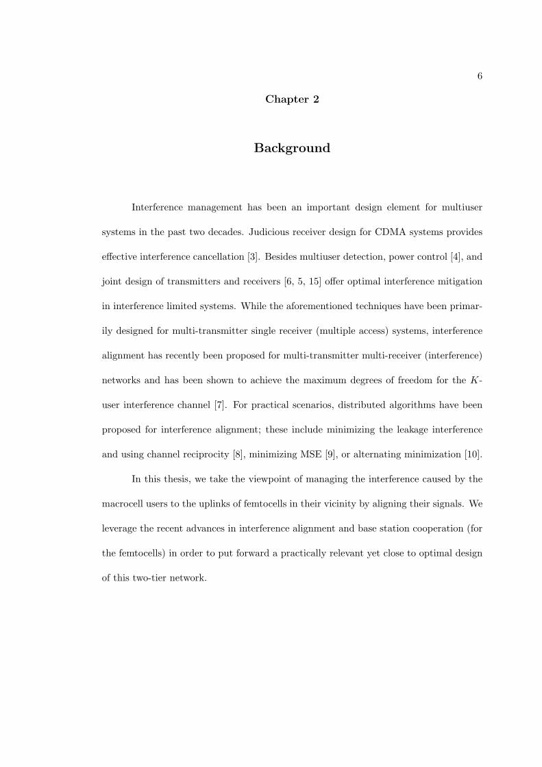
In a basic femtocell network as given in Fig.2.1, the femtocell base station is
connected to the internet broadband router. The fact that femtocell users (FU) utilize
the internet backhaul reduces the load on the macrocell network, enabling the resources
to be allocated to the truly mobile users. Another reason for employing femtocells is to
increase the coverage, due to the poor indoor coverage experienced with current wireless
standards and even no coverage in rural areas. As the femtocells are designed mainly for
indoor use, and are connected to the internet backhaul instead of the macrocell network,
they can operate and provide cellular coverage even in areas that has no cellular backhaul,
but only the internet backhaul.
Another reason for femtocells becoming popular among the wireless operators is
that they require no infrastructure, as they are purchased and installed by the end user.
8
Fig. 2.1. A basic femtocell network

9
Fig. 2.2. Comparison of coverage areas of various cell sizes
This fact reduces the construction and maintenance costs. The comparison of the cov-
erage areas for different cell types [25] is given in Fig.2.2. The difference between the
femtocells and other cell types is the fact that picocells, microcells and macrocells are
constructed and maintained by the network operator, which makes it possible to em-
ploy centralized interference management and scheduling methods. The femtocells are
installed by their own users, and the randomness of their locations require more sophis-
ticated interference management methods to be employed, which should be adaptable to
their environment. Femtocells are low power devices, and are designed to operate close
to the mobile user they are serving. As a result the battery life of the mobile devices are
higher when they are using femtocells for communication.
It is preferred for the femtocells to share the frequency band with the existing
macrocell network, as the licensed band is highly populated, and frequency is a scarce

10
Fig. 2.3. Spectrum access for femtocells
resource. The spectrum access types for femtocells are shown in Fig.2.3. There are
mainly three access types; dedicated, co-channel and hybrid [25]. In the dedicated access
type, the femtocells and the macrocell have separate frequency bands, which increases
the interference management performance, but it not preferred due to the inefficient
use of the frequency spectrum. In the co-channel access type, the femtocells and the
macrocell operate in the same frequencies, which increases the frequency reuse, but
requires advanced interference management techniques to be employed due to co-channel
interference. In the hybrid spectrum access, separate frequency bands are allocated to
the femtocells and the macrocells as long as the load on the macrocell network is not
very high. When there is excessive load in the macrocell network, some macrocell users
are allowed to use the frequency bands of the femtocells. This notion brings another
11
idea for the access permissions for the femtocell and macrocell users, which is called the
open and closed access. In the open access, all subscribers registered with an operator
can access all base stations, whether it is a femtocell base station or a macrocell base
station. In the closed access, only a limited number of users are permitted to access the
access point. The performance of femtocell open and closed access from both femtocell
owner and network operator’s point of view is evaluated in [29].
The importance of sharing the frequency resources between the two tiers, com-
bined with the ad hoc nature of femtocells, make cross tier interference management
challenging, and the centralized solutions impractical.
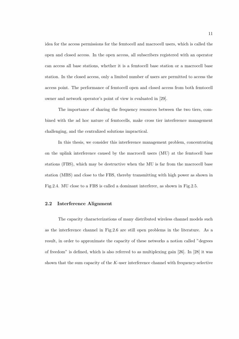
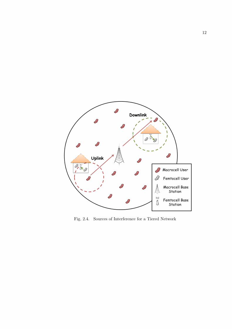
In this thesis, we consider this interference management problem, concentrating
on the uplink interference caused by the macrocell users (MU) at the femtocell base
stations (FBS), which may be destructive when the MU is far from the macrocell base
station (MBS) and close to the FBS, thereby transmitting with high power as shown in
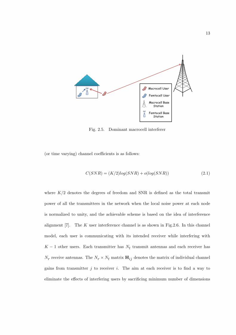
Fig.2.4. MU close to a FBS is called a dominant interferer, as shown in Fig.2.5.
2.2 Interference Alignment
The capacity characterizations of many distributed wireless channel models such
as the interference channel in Fig.2.6 are still open problems in the literature. As a
result, in order to approximate the capacity of these networks a notion called ”degrees
of freedom” is defined, which is also referred to as multiplexing gain [26]. In [28] it was
shown that the sum capacity of the K-user interference channel with frequency-selective
12
Fig. 2.4. Sources of Interference for a Tiered Network
13
Fig. 2.5. Dominant macrocell interferer
(or time varying) channel coefficients is as follows:
C(SNR) = (K/2)log(SNR) + o(log(SNR)) (2.1)
where K/2 denotes the degrees of freedom and SNR is defined as the total transmit
power of all the transmitters in the network when the local noise power at each node
is normalized to unity, and the achievable scheme is based on the idea of interference
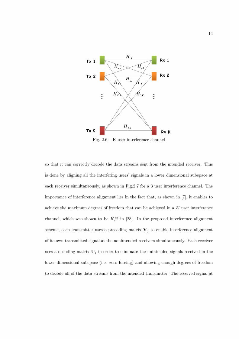
alignment [7]. The K user interference channel is as shown in Fig.2.6. In this channel
model, each user is communicating with its intended receiver while interfering with
K − 1 other users. Each transmitter has Nt transmit antennas and each receiver has
Nr receive antennas. The Nr ×Nt matrix Hij denotes the matrix of individual channel
gains from transmitter j to receiver i. The aim at each receiver is to find a way to
eliminate the effects of interfering users by sacrificing minimum number of dimensions
14
Fig. 2.6. K user interference channel
so that it can correctly decode the data streams sent from the intended receiver. This
is done by aligning all the interfering users’ signals in a lower dimensional subspace at
each receiver simultaneously, as shown in Fig.2.7 for a 3 user interference channel. The
importance of interference alignment lies in the fact that, as shown in [7], it enables to
achieve the maximum degrees of freedom that can be achieved in a K user interference
channel, which was shown to be K/2 in [28]. In the proposed interference alignment
scheme, each transmitter uses a precoding matrix Vj to enable interference alignment
of its own transmitted signal at the nonintended receivers simultaneously. Each receiver
uses a decoding matrix Ui in order to eliminate the unintended signals received in the
lower dimensional subspace (i.e. zero forcing) and allowing enough degrees of freedom
to decode all of the data streams from the intended transmitter. The received signal at

15
Fig. 2.7. Interference Alignment in a 3 user interference channel
16
the ith receiver is as given in the following:
yi =
K∑j=1
HijVjsj + ni (2.2)
where Vj denotes the Nt×dj precoding matrix, sj is the (dj×1) vector of independently
encoded symbols, dj is the number of information bits transmitted by the jth user. The
noise received at the ith receiver is represented by ni, which consists of independent zero
mean Gaussian random variables with E{niniH} = σ2I, and ni
H denotes the Hermitian
transpose of the vector ni. The conditions at the receivers for interference alignment are
given as:
H12V2 = H13V3 = . . . = H1KVK
H21V1 = H23V3 = . . . = H2KVK
...
HK1V1 = HK2V2 = . . . = HK(K−1)V(K−1)
(2.3)
The signal at the ith receiver after the decoding matrix is applied is given as:
Yi = Ui∗Yi (2.4)

17
where Ui∗ denotes the conjugate transpose of the matrix Ui. For perfect interference
alignment, the resulting system should ensure the following conditions:
Ui∗HijVj = 0 ∀j = i
rank(Ui∗HiiVi) = di (2.5)
From these conditions it can be seen that, at each receiver the interference should be
aligned into the null space of the decoding matrix and the rank of the resulting matrix
should be equal to the number of symbols to be detected, in order to detect them
properly. As a result the effective channel for user i can be represented as:
Yi = Ui∗HiiVisi +Ui
∗ni (2.6)
The exact interference alignment scheme for a 3 user interference channel was proposed
in [7]. However, the exact closed form solutions for channels with number of users
K > 3 are not known. As a result, many distributed algorithms have emerged to
find the approximate precoding and decoding matrices that take into account different
objective functions, including minimizing the leakage interference [8], alternating mini-
mization [10], maximizing the SINR [8], or minimizing MSE [9]. The common point of
these algorithms is that they update the precoding/decoding matrices for a given decod-
ing/precoding matrix set iteratively, and they are not jointly convex over all precoding
and decoding matrices. As a result they cannot guarantee convergence to the global
18
optima, and may end up at a local optima. Some of these algorithms are discussed in
the following sections.
Recently it was shown that also the real-world performance of interference align-
ment outperforms conventional multiuser communication methods such as TDMA [27].
The measurements in [27] are done using practical MIMO channels and the exact interfer-
ence alignment scheme for a 3 user interference channel and distributed algorithms were
implemented using a 2× 2 MIMO testbed. Since the distributed algorithms converge to
the local optima due to their nonconvex nature, the algorithms were implemented for a
number of different starting points and the one giving the best local minima was chosen.
2.2.1 Minimum Leakage Interference IA
This algorithm seeks the perfect interference alignment by minimizing the leakage
interference [8], calculated as the trace of the interference covariance matrix, given in
the following equation:
min(Uk)
∗Uk=Itrace(Uk
∗QkUk) (2.7)
where Qk =∑K
j=1j =k
PsHkjVjVj∗Hkj
∗ and Ps is the transmitted symbol power. I
denotes the identity matrix.
The algorithm aims to align all the interfering signals in a lower dimensional
subspace at each receiver simultaneously. At each iteration the coding matrices are
updated in such a way that the signal is transmitted along the n smallest eigenvectors,
i.e. in the directions of the n smallest eigenvalues of the leakage interference matrix. Then
the roles of the transmitters and receivers are changed by exploiting channel reciprocity,
19
the precoders now become decoders and the decoders now become precoders, and the
same procedure is applied to the new precoder/decoders.
This algorithm was shown to converge in [8]. However, due to the nonconvex
nature of the problem, one cannot assure the algorithm converges to the global optima,
it will possibly converge only to a local optima. Although the algorithm provides good
performance in high SINR (Signal to Interference plus Noise Ratio), for low to moderate
SNR values, it was shown in [8] that the performance is poor since the objective function
does not aim to maximize the received SINR at the intended receiver.
2.2.2 Max SINR
Max SINR algorithm was developed in [8] due to the fact that Minimum Leakage
Interference algorithm only seeks perfect interference alignment and does not consider
about the received SINR values. Max SINR algorithm aims to maximize the received
SINR at each receiver, by find the unit vector U lkthat maximizes the SINR in the lth
stream of the kth user, which is given as:
max SINRkl =(Ul
k)∗HkkV
lk(Vl
k)∗HkkU
lkPs
UlkBklU
lk
(2.8)
where Bkl =∑K
j=1Ps
∑djd=1HkjV
dj(Vd
j)∗H∗
kj− PsH
∗kk
+ INtand INt
is the Nt ×Nt
identity matrix. Ps is the transmitted symbol power. Again the precoder and decoders
are updated iteratively and the role of the precoder and decoders are changed at each
iteration.

20
2.2.3 Alternating Minimization
Alternating minimization is the technique to tackle the optimization problems in
which finding an exact solution over two variables is difficult, but optimizing over one
variable while fixing the others is relatively easy. In this method the aim is to find the
minimum of d(A,B) where d denotes the distance in any metric space. And A and B
denote the sets of optimization variables. Here the sequence {Ak}∞(k=0)
and {Bk}∞(k=0)
are obtained by an iterative algorithm, that is first fixing Bk and optimizing over A and
then fixing Ak and optimizing over B. The algorithm, illustrated in Fig.2.8, is given as
follows:
Ak+1 = argminA∈A
d(A,Bk)
Bk+1 = argminB∈B
d(Bk+1, A) (2.9)
A ∈ A, B ∈ B ∀k (2.10)
The idea of using alternating minimization for interference alignment was proposed in
[10]. The received signals are projected onto a subspace which is called the interference
subspace. The objective of the algorithm is to minimize the sum of the distances between
the projected signals to the interference subspace, in which the sum is done over the
interfering users. The precoding and orthogonal projection matrices Fl and Ck for the
lth transmitter and kth receiver are find via alternating minimization, which is shown
to converge, but whether it converges to the global optima is unknown. The received

21
Fig. 2.8. Alternating Minimization
signal at the kth receiver is given as follows:
yk = HkkFksk +∑l =k
HklFlsl + nk (2.11)
The objective function is represented as:
minF∗lFl=I,∀l
C∗kCk=I,∀k
K∑k=1
K∑l=1l =k
∥HklFl −CkC∗kHklFl∥
2F
(2.12)
In this approach the optimization is done over 2K variables, where 2K − 1 variables are
temporarily fixed and the optimization is done over the remaining variable.
22
2.2.4 Minimum Mean Squared Error IA
Another distributed algorithm [9] aims to minimize the sum mean squared-error
by using precoding/decoding matrices at each transmitter/receiver, which is given as:
minv1,...,vkg1,...,gk
K∑k=1
ϵk (2.13)
where ϵk = E{|sk − sk|2}, vk is the precoding vector of the kth user, gk is the decoding
vector for the kth user, and sk is the estimated symbol of the kth user.
2.2.5 Least Squares Approach for IA
Least squares approach [11] uses an alternative representation for interference
alignment given as:
C(H12w2) = C(H13w23) = · · · = C(H1KwK) (2.14)
C(H21w1) = C(H23w3) = · · · = C(H2KwK) (2.15)
...
C(HK1w1) = C(HK2w2) = · · · = C(HK(K−1)w(K−1)) (2.16)
where C(.) represents that the interfering signals span the same subspace. For each
specific receiver, each interfering signal is represented by a linear combination of the
23
remaining interfering signals using scalar coefficients, which is given as:
H12w2 = α13H13w23 = · · · = α1KH1KwM (2.17)
H21w1 = α23H23w3 = · · · = α2KH2KwK (2.18)
...
HK1w1 = αK2HK2w2 = · · · = αK(K−1)HK(K−1)w(K−1) (2.19)
Using the precoders and the associated coefficients, the interference alignment expres-
sions can be combined in a single matrix representation as:
Hw = 0 (2.20)
where w = [wT1
wT2. . .wT
K]T and
H =
0 H12 −α13H13 0 . . . 0
0 H12 0 −α14H14 . . . 0
......
.... . .
......
0 H12 0 . . . 0 −α1KH1K
......
.... . .
......
HK1 −αK2HK2 0 . . . 0 0
......
.... . .
......
HK1 0 0 . . . 0 −αK(K−1)HK(K−1)

24
The proposed approach for finding the precoding matrices is making the norm of this
expression as close to zero as possible, from which follows the notion of least squares
approach for interference alignment [11]:
minw∗w=1
∥Hw∥ (2.21)
As a result of the unitary assumption on w, the solution for w is the eigenvector of Hw
that corresponds to its smallest eigenvalue.

25
Chapter 3
Interference Alignment for Cooperative
MIMO Femtocell Networks
3.1 Introduction
In this chapter, we propose a method for mitigating the uplink interference caused
by the macrocell users (MU) at the femtocell base stations (FBS). The proposed method
uses interference alignment for restricting the received interference from MUs to a lower
dimensional subspace at multiple FBSs simultaneously. Our approach considers im-
proving the performance of femtocell users by aligning the macrocell interference, while
satisfying the QoS requirements of the macrocell users, in terms of the minimum SINR
required at the macrocell base station. As a solution, we propose to use SDP relaxations
with eigenvector approximation for interference alignment in tiered networks with SINR
constraints.
The remainder of the chapter is organized as follows: In Section II, we introduce
the system model. Interference alignment for macrocell users is presented in Section III.
Section IV describes the precoding and decoding scheme for femtocell users. In Section
V, the numerical results and simulations are discussed. We conclude the chapter in
Section VI. The notation used in this chapter is as follows: We use lower (upper) bold
case letters for vectors (matrices). XH is used to denote the Hermitian transpose, X†

26
as the pseudo-inverse of matrix X, and ⊗ for the Kronecker product. Finally, trace(X)
represents the trace of matrix X.
3.2 System Model
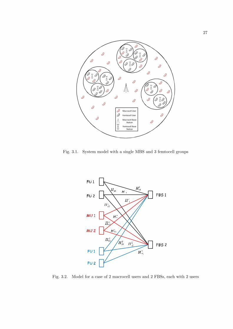
We consider an uplink femtocell network as shown in Fig. 3.1 consisting of a
macrocell base station (MBS) at the center with No receive antennas. The macrocell
coverage area is partitioned into smaller cells of fixed radius in which the mobile users and
base stations can cooperate with each other. Suppose such a group consists of F femtocell
base stations (FBS), with Uf users in the f th femtocell (FU) and M macrocell users
(MU). We have Nt transmit antennas at each mobile device and Nf receive antennas at
the f th FBS. Then the signal received at the kth FBS is given by
yk =
Uk∑i=1
Hkkiwkiski
+
F∑f=1f =k
Uf∑u=1
Hfkuw
fusfu+
M∑m=1
Hokm
womsom
+ nk (3.1)
where Hfku denotes the channel from the uth user of the f th femtocell to the kth FBS,
Hokm
is the channel from the mth MU to the kth FBS, wfu
and sfuare the precoding
vector and the message bit of the uth user of the f th femtocell, wom
and som
are the
precoding vector and message bit of the mth MU, nk is a vector of independent zero
mean Gaussian random variables with E{nknkH} = σ2I. The channels considered are
Rayleigh fading channels and the path loss is modeled using the ITU-R channel model
[23]. We used rank 1 precoders to reduce the complexity of the algorithm and to avoid
27
Macrocell User
Femtocell User
Macrocell Base Station
Femtocell Base Station
Fig. 3.1. System model with a single MBS and 3 femtocell groups
Fig. 3.2. Model for a case of 2 macrocell users and 2 FBSs, each with 2 users

28
feasibility problems due to the large number of users. We assume sfuand so
m= ±1 for
u = 1, . . . , Uf , f = 1, . . . , F , and m = 1, . . . ,M . An example model is given in Fig.3.2
for 2 macrocell users and 2 FBSs, each with 2 users.
3.3 Interference Alignment with Successive SDP Relaxations
For simplicity, we will neglect the uplink interference caused at a FBS by the
users of other femtocells, and consider only the (dominant) interference caused by the
macrocell users. We will use the condition for interference alignment proposed in [11]:
Ho11wo1= α12H
o12wo2= · · · = α1MHo
1MwoM
(3.2)
Ho21wo1= α22H
o22wo2= · · · = α2MHo
2MwoM
(3.3)
...
HoF1
wo1= αF2H
oF2
wo2= · · · = αFMHo
FMwoM
(3.4)
where αfm is a constant and the equations denote that all interfering users span the
same column space at each FBS. That is, each interfering signal is represented by a linear
combination of other interfering signals, represented by different coefficients. Using the
precoders and the associated coefficients, expressions (3.2)-(3.4) can be combined in a
single matrix representation as in (3.5), as proposed in [11]. Then the condition of perfect
interference alignment is equal to the expression being equal to zero (3.5). Therefore, one
approach for finding the interference aligning precoding matrices is to make the norm of
this expression as close to zero as possible as in (3.6), from which follows the notion of

29
least squares approach for interference alignment, proposed in [11].
Hw = 0 (3.5)
where
H =
Ho11
−α12Ho12
0 . . . 0
Ho11
0 −α13Ho13
. . . 0
......
.... . .
...
Ho11
0 0 . . . −α1MHo1M
......
.... . .
...
HoF1
−αF2HoF2
0 . . . 0
HoF1
0 −αF3HoF3
. . . 0
......
.... . .
...
HoF1
0 0 . . . −αFMHoFM
w =
[wo1T wo
2T wo
3T . . . wo
M−1T wo
MT
]T
We will follow this definition for interference alignment, however, our solution follows
a SDP relaxation method to solve the norm minimization problem that satisfies the
individual minimum SINR requirements for each macrocell user, which incorporates
successive SDP relaxations [20] and rank-one approximation. The interference alignment
problem in (3.5) can be regarded as a least squares (LS) problem [11]. In fact, (3.5)

30
denotes a set of linear equations and the LS approach is a conventional method to
approximate the solution. In order to satisfy QoS requirements, we define an individual
SINR constraint for each macrocell user. The problem is thus given by:
minimizewo1,...,wo
M
∥Hw∥
subject to SINRi ≥ γi
(woi)Hwo
i≤ Po
ii = 1, . . . ,M
(3.6)
where Poidenotes the maximum transmit power of the ith macrocell user, γi denotes the
minimum SINR threshold of the ith macrocell user, and SINRi is given as in (3.8).
SINRi =(wo
i)H (Ho
oi)HHo
oiwoi∑M
n=1n =i
(won)H (Ho
on)HHo
onwon+B+ σ2
(3.7)
where
B =
F∑f=1
Uf∑u=1
(wfu)H(Hf
ou)HHfou
wfu
(3.8)
where Hoon
denotes the channel from the nth macrocell user to the MBS. Then the
equivalent problem can be written as:
minimizewo1,...,wo
M
trace(RW)
subject to trace((Roi − γi∑n =i
Ron)W) ≥ γiσ2
31
trace((diag(ei)⊗ I(Nt×Nt))W) ≤ Po
i
rank(W) = 1
W ≽ 0, i = 1, . . . ,M
(3.9)
where R = HHH, W = wwH , Ron = (Hoon
)HHoon
, Ron = diag(en) ⊗ Ron, and
en = [0 . . . 010 . . . 0]T is an (M × 1) unit vector with 1 as the nth element and zeros
elsewhere. I(Nt×Nt)denotes the (Nt × Nt) identity matrix. By relaxing the rank 1
constraint, we obtain the semidefinite relaxation [19] of the problem:
minimizewo1,...,wo
M
trace(RW)
subject to trace((Roi − γi∑n =i
Ron)W) ≥ γiσ2
trace((diag(ei)⊗ I(Nt×Nt))W) ≤ Po
i
W ≽ 0, i = 1, . . . ,M
(3.10)
The SDP in (3.9) can be solved efficiently by software such as SeDuMi[13]. In case the
resulting solution has a higher rank than one, we can use eigenvector approximation [12],
in which the vector w is approximated as the eigenvector q1 corresponding to the largest
eigenvalue of W, scaled by the square root of the largest eigenvalue of W, λ1, i.e.,
W = wwH =∑i
λiqiqHi
(3.11)
w ∼=√
λ1q1 (3.12)

32
After this step, the coefficients are determined using the conditions in (3.2)-(3.4) [11], as
given by:
αkm = (Hokm
wom)†(Ho
k1wo1) (3.13)
(Hokm
wom)† = ((Ho
kmwom)H (Ho
kmwom))−1(Ho
kmwom)H (3.14)
3.4 Minimum sum MSE with Coordinated Zero-Forcing
Femtocell users can either cooperate and contribute interference alignment, which
may increase the load on the backhaul or they can try to improve their own performance.
As a suitable precoding-decoding scheme for the second case, each FBS may try to
minimize the sum MSE of its own users, by zero-forcing the aligned macrocell users.
A coordinated zero-forcing beamforming for SINR maximization was proposed in [14],
which uses the ideas from [15] and [16].
We will use a precoding-decoding scheme that minimizes the sum MSE at the
FBSs while zero-forcing the aligned interference from the macrocell users. The estimated
bit of the jth user of the kth femtocell is given as:
skj=
Uk∑i=1
(gkj)HHk
kiwkiski+
F∑f=1f =k
Uf∑u=1
(gkj)HH
fkuw
fusfu
+
M∑m=1
(gkj)HHo
kmwomsom
+ (gkj)Hnk (3.15)
where gkjis the decoding vector for the jth user of the kth femtocell. Since the inter-
ference caused by other femtocells are very small compared to the intracell interference,
33
for simplicity we will regard intercell femtocell interference as noise, which is given as:
nk =
F∑f=1f =k
Uf∑u=1
Hfkuw
fusfu+ nk (3.16)
Using the conditions in (3.2)-(3.4) and (3.15), the minimum sum MSE at the FBS prob-
lem can be formulated as:
minimizewk1,...,wk
Uk
gk1,...,gk
Uk
Uk∑j=1
∥skj− sk
j∥2
subject to (gkj)HHo
k1wo1= 0
(wkj)Hwk
j≤ Pk
jj = 1, . . . , Uk
(3.17)
or equivalently
minimizewk1,...,wk
Uk
gk1,...,gk
Uk
Uk∑j=1
[|(gk
j)HHk
kjwkj− 1|2
+
Uk∑i=1i=j
|(gkj)HHk
kiwki|2 + ∥gk
j∥22σ2
]
subject to (gkj)HHo
k1wo1= 0
(wkj)Hwk
j≤ Pk
jj = 1, . . . , Uk
(3.18)

34
where Pkj
is the maximum transmit power of the jth user of the kth femtocell, and
E{nk(nk)H} = σ2I. The zero forcing constraint in (3.18) implies that gk
jshould be in
the null space of (Hok1
wo1) [17], from which we can define a decoding vector such as:
gkj= Uo
kvkj
(3.19)
where [U0kU1k]ΛkVk is obtained from the SVD of Ho
k1wo1and the columns of Uo
kis a
nullspace basis of Hok1
wo1. If we let (U0
k)HHk
kj= Hk
kj, the problem in (3.18) is equal
to:
minimizewk1,...,wk
Uk
vk1,...,vk
Uk
Uk∑j=1
[|(vk
j)HHk
kjwkj− 1|2
+
Uk∑i=1i=j
|(vkj)HHk
kiwki|2 + ∥vk
j∥22σ2
](3.20)
subject to (wkj)Hwk
j≤ Pk
jj = 1, . . . , Uk
The problem in (3.20) is convex in wkjif the all other vk
jare fixed, and convex in vk
j
if all other wkj
are fixed. Using this property, we can use an iterative algorithm by
first fixing the decoding matrices and obtaining the precoding matrices, then fixing the
precoding matrices to obtain the decoding matrices. An iterative procedure for obtaining
the optimal coding vectors is used in [18] where the transmit precoding vector had unit
norm. After writing the Lagrangian for the problem in (3.20), from the KKT conditions
35
we have the optimal precoding and decoding vectors as:
vkj=
( Uk∑i=1
(Hkkiwki)(Hk
kiwki)H + σ2I
)−1Hkkjwkj
(3.21)
wkj=
( Uk∑i=1
(Hkkj)Hvk
i(vk
i)HHk
kj+ µk
jI
)−1(Hk
kj)Hvk
j(3.22)
for j = 1, . . . , Uk. We determine µkjsuch that (wk
j)Hwk
j= Pk
j.
3.5 Minimum sum MSE without Zero Forcing
In this section we apply MMSE precoding/decoding for the femtocell users, with-
out zero forcing the aligned interference from the macrocell users first. For the new
approach, the problem in (3.17) becomes: Using the conditions in (3.2)-(3.4) and (3.15),
the minimum sum MSE at the FBS problem can be formulated as:
minimizewk1,...,wk
Uk
gk1,...,gk
Uk
Uk∑j=1
|skj− sk
j|2
subject to (wkj)Hwk
j≤ Pk
jj = 1, . . . , Uk
(3.23)
36
where the zero forcing requirement for the macrocell users is removed from the problem
in (3.17). The problem can also be represented in the following form:
minimizewk1,...,wk
Uk
gk1,...,gk
Uk
Uk∑j=1
[|(gk
j)HHk
kjwkj− 1|2 +
Uk∑i=1i =j
|(gkj)HHk
kiwki|2
+
M∑m=1
|(gkj)HHo
kmwom|2 + ∥gk
j∥22σ2
]
subject to (wkj)Hwk
j≤ Pk
jj = 1, . . . , Uk
(3.24)
where the problem in (3.24) is convex in wkjif the all other gk
jare fixed, and convex
in gkjif all other wk
jare fixed. We can again make use of this to obtain an iterative
algorithm by first fixing the decoding matrices and determining the precoding matrices,
then fixing the precoding matrices determining the decoding matrices. An iterative
procedure is used in [18] to obtain the coding vectors where the transmit precoding
vector had unit norm. After writing the Lagrangian and using the KKT conditions, the
resulting expressions for the optimal precoders and decoders of the femtocell users are
found to be as follows:
gkj=
( Uk∑i=1
(Hkkiwki)(Hk
kiwki)H +
M∑m=1
(Hokm
wom)(Ho
kmwom)H + σ2I
)−1Hkkjwkj
(3.25)
wkj=
( Uk∑i=1
(Hkkj)Hgk
i(gk
i)HHk
kj+ µk
jI
)−1(Hk
kj)Hgk
j(3.26)
37
for j = 1, . . . , Uk. We determine µkjsuch that (wk
j)Hwk
j= Pk
j.
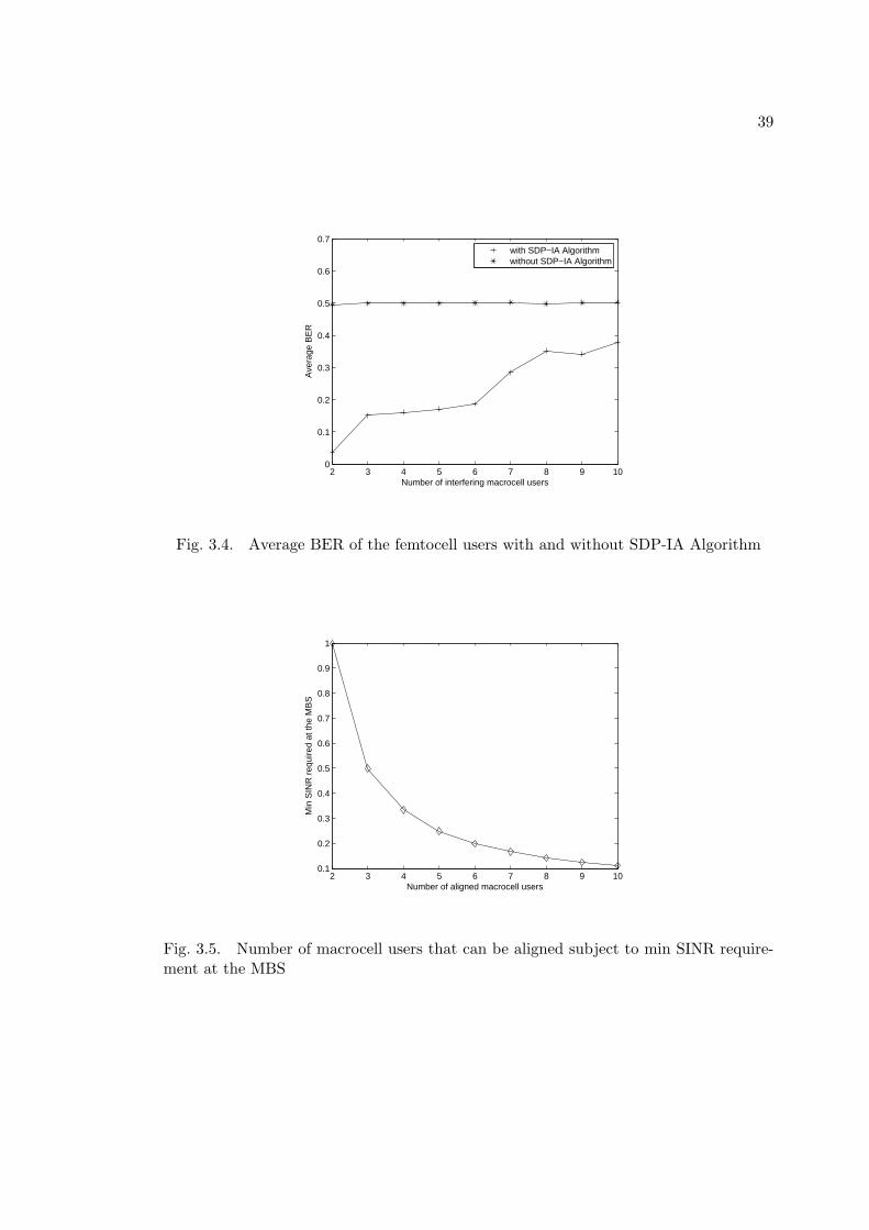
3.6 Simulation Results
Simulations are performed to compare the performance of the proposed macrocell
interference alignment with that of the setting where macrocell users (MU) minimize
their sum MSE at the MBS, without regard to femtocell users (FU). The MBS has a
coverage radius of 2km, the group of FBSs close to each other is denoted by an area of
150m radius, placed randomly according to a uniform distribution within the coverage
radius of the MBS, and the MUs within this area apply interference alignment jointly.
We consider 3 FBSs each with a radius of 30m coverage. Each FBS has 3 users, and
each mobile user has 4 transmit antennas. FBSs have 4 receive antennas. Noise power
is assumed to be −110dB. Power control at both FBS and MBS is used to compensate
for the path loss. The maximum transmit power of each user is 1W.
The convergence of the SDP-IA algorithm for 10 macrocell users and a minimum
SINR requirement of 0.1 at the MBS is presented in Fig.3.3. The comparison of the SDP-
IA with coordinated zero forcing scheme with the one with no interference alignment in
terms of average BER versus the number of MUs interfering to the femtocell group
is given in Fig.3.4. For the case when no interference alignment is applied, the only
objective for the MUs is to minimize the sum MSE at the MBS. The number of MUs
that can be aligned for different minimum SINR requirements at the MBS is depicted in
Fig.3.5 for the SDP-IA with coordinated zero forcing algorithm.
The results show that the performance of the FUs in terms of average BER is
significantly better when compared to the case when the interfering MUs only consider

38
1 2 3 4 5 6 7 8 9 100.5
1
1.5
2
2.5x 10
−6
iteration
leak
ed in
terf
eren
ce
Fig. 3.3. Convergence results of the SDP-IA Algorithm
their own performance and minimize the sum MSE at the MBS. It was observed in the
simulations that, the received SINR constraints of the MUs in the second case do not
satisfy a minimum and may cause an outage in voice applications. The feasibility of
the minimum SINR constraints is a main limitation in this system: as the minimum
SINR constraints of MUs are increased, the maximum number of MUs that can be
aligned simultaneously decreases significantly. The average BER of the femtocell users
with respect to the number of interfering macrocell users for the SDP-IA without zero
forcing algorithm is given in Fig.3.6 for a single femtocell group. From Fig.3.6 it can be
seen that the average BER of the femtocell users have decreased, correspondingly their
performances have improved.
39
2 3 4 5 6 7 8 9 100
0.1
0.2
0.3
0.4
0.5
0.6
0.7
Number of interfering macrocell users
Ave
rage
BE
R
with SDP−IA Algorithmwithout SDP−IA Algorithm
Fig. 3.4. Average BER of the femtocell users with and without SDP-IA Algorithm
2 3 4 5 6 7 8 9 100.1
0.2
0.3
0.4
0.5
0.6
0.7
0.8
0.9
1
Number of aligned macrocell users
Min
SIN
R r
equi
red
at th
e M
BS
Fig. 3.5. Number of macrocell users that can be aligned subject to min SINR require-ment at the MBS

40
3 4 5 6 7 8 9 100
0.5
1
1.5
2
2.5
3
3.5
4
4.5x 10
−4
Number of interfering macrocell users
Ave
rage
BE
R
Fig. 3.6. Average BER of the femtocell users with SDP-IA Algorithm with MMSEprecoding/decoding for femtocell users

41
Chapter 4
Distributed Multiuser MIMO Interference Alignment
4.1 Introduction
In the previous chapter, a method for dealing with large number of macrocell
users in a femtocell network was proposed. This method combined the ideas of interfer-
ence alignment and semidefinite relaxation in order to restrict the macrocell interference
in a lower dimensional subspace, simultaneously at multiple base stations, so that the
macrocell interference could be cancelled at each femtocell base station, using a relatively
small number of antennas compared to the number of interfering macrocell users. Since
the femtocell devices have an ad-hoc nature, unlike the microcell and picocell networks,
the interference management and scheduling cannot be done in a centralized manner.
Therefore adaptive schemes should be proposed that can adjust to the current specifi-
cations of the tiered cellular network. For this purpose, in this chapter, we first define
a new interference alignment algorithm that determines the precoders and the “aligned
subspaces” iteratively. This is because using one dimensional precoders or beamformers
will cause feasibility problems if we want to align a larger number of interferers. Another
reason for introducing the new distributed algorithm is that the interference alignment
algorithm with semidefinite relaxation operated in a centralized manner, which requires
a processing unit to gather information from both tiers, and to send the resulting infor-
mation back to the users, which may not be desirable in a tiered network, due to the load

42
it will add to the network and for security and privacy reasons. Therefore, a distributed
algorithm is highly desirable in these networks, especially when we are designing schemes
that consider the whole femtocell network, instead of a smaller part of it, as we have
considered in the previous chapters.
This chapter is organized as follows. In the next section the iterative interference
alignment algorithm is described for a K-user interference channel. In Section 4.3, this
algorithm is considered for the case when the channel information available at the trans-
mitters is imperfect. We generalize the distributed interference alignment algorithm for
the tiered networks in Section 4.4.
4.2 Distributed Interference Alignment for the K-user Interference
Channel
In this section, the proposed multiantenna distributed interference alignment al-
gorithm is described for a K-user interference channel as shown in Fig.2.6, with K trans-
mitters and K receivers. The transmitter and receivers are assumed to have perfect
Channel State Information (CSI).
The aim is to determine the precoder of each transmitter and the interference
subspace at each receiver such that the received signals from all the interfering users are
restricted in a lower dimensional subspace simultaneously at each receiver. The channel
considered in this section is a K-user interference channel, but the results can be extended
to the two-tier systems such as femtocell networks, as will be done in Section 4.4.

43
System Model
For a K-user interference channel, the signal received at the kth receiver is given by:
yk = HkkWksk +
K∑j=1j =k
HkjWjsj + nk (4.1)
where yk represents the (Nr × 1) received signal vector at the kth receiver, Hkj is
the (Nr × Nt) channel matrix from the jth transmitter to the kth receiver. Wk is
the (Nt × dk) precoding matrix. sk denotes the (dk × 1) transmit vector of the kth
transmitter where dk denotes the number of signals to be transmitted from the kth
transmitter, Nt and Nr denotes the number of transmit/receive antennas, respectively.
where nk ∼ CN (0, σ2I) is the noise vector at the kth receiver. E{sj(sj)H} = I.
Problem Formulation
The interference alignment condition requires that, at each receiver, all the interfering
signals span the same subspace, which can be interpreted as [11]:
H12W2 ⊂ H13W3 ⊂ . . . ⊂ H1KWK ⊂ V1
H21W1 ⊂ H23W3 ⊂ . . . ⊂ H2KWK ⊂ V2
...
HK1W1 ⊂ HK2W2 ⊂ . . . ⊂ HK(K−1)W(K−1) ⊂ VK
(4.2)
44
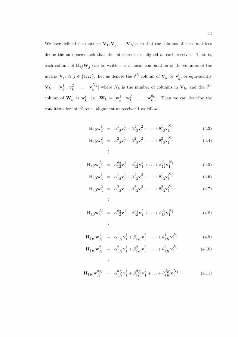
We have defined the matrices V1,V2, . . . ,VK such that the columns of these matrices
define the subspaces such that the interference is aligned at each receiver. That is,
each column of HijWj can be written as a linear combination of the columns of the
matrix Vi, ∀i, j ∈ {1,K}. Let us denote the ith column of Vk by vik, or equivalently
Vk = [v1k
v2k
. . . vNkk ] where Nk is the number of columns in Vk, and the ith
column of Wk as wik, i.e. Wk = [w1
kw2k
. . . wdkk ]. Then we can describe the
conditions for interference alignment at receiver 1 as follows:
H12w12
= α112v11+ β1
12v21+ . . .+ θ1
12vN11 (4.3)
H12w22
= α212v11+ β2
12v21+ . . .+ θ2
12vN11 (4.4)
...
H12wd22 = α
d212v
11+ β
d212v
21+ . . .+ θ
d212v
N11 (4.5)
H13w13
= α113v11+ β1
13v21+ . . .+ θ1
13vN11 (4.6)
H13w23
= α213v11+ β2
13v21+ . . .+ θ2
13vN11 (4.7)
...
H13wd33 = α
d313v
11+ β
d313v
21+ . . .+ θ
d313v
N11 (4.8)
...
H1Kw1K
= α11K
v11+ β1
1Kv21+ . . .+ θ1
1KvN11 (4.9)
H1Kw2K
= α21K
v11+ β2
1Kv21+ . . .+ θ2
1KvN11 (4.10)
...
H1KwdKK = α
dK1Kv1
1+ β
dK1Kv2
1+ . . .+ θ
dK1Kv
N11 (4.11)
45
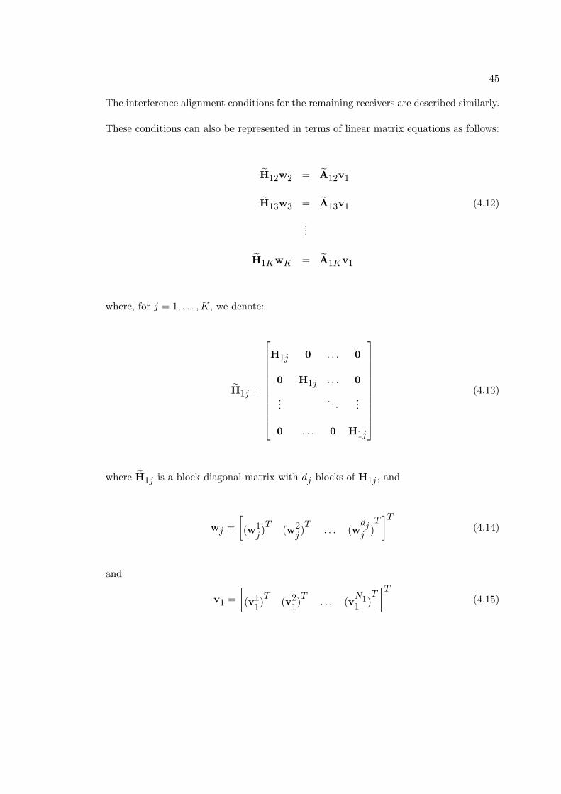
The interference alignment conditions for the remaining receivers are described similarly.
These conditions can also be represented in terms of linear matrix equations as follows:
H12w2 = A12v1
H13w3 = A13v1 (4.12)
...
H1KwK = A1Kv1
where, for j = 1, . . . ,K, we denote:
H1j =
H1j 0 . . . 0
0 H1j . . . 0
.... . .
...
0 . . . 0 H1j
(4.13)
where H1j is a block diagonal matrix with dj blocks of H1j , and
wj =
[(w1
j)T
(w2j)T
. . . (wdjj )
T]T
(4.14)
and
v1 =
[(v1
1)T
(v21)T
. . . (vN11 )
T]T
(4.15)
46
and
A1j =
α11j
β11j
. . . θ11j
α21j
β21j
. . . θ21j
.... . .
...
αdj1j β
dj1j . . . θ
dj1j
⊗ INr×Nr
(4.16)
where INr×Nrdenotes the (Nr ×Nr) identity matrix, and
A1j =
α11j
β11j
. . . θ11j
α21j
β21j
. . . θ21j
.... . .
...
αdj1j β
dj1j . . . θ
dj1j
(4.17)
When we follow this procedure for each receiver, the necessary conditions for interference
alignment at K receivers can be represented as:
H12w2 = A12v1, H13w3 = A13v1, . . . H1KwK = A1Kv1
H21w1 = A21v2, H23w3 = A23v2, . . . H2KwK = A2Kv2
...
HK1w1 = AK1vK , HK2w2 = AK2vK , . . . HK(K−1)wK(K−1) = AK(K−1)vK
(4.18)
Using these conditions, we can derive the following matrix equalities for obtaining the
vector form of the precoding matrices, which were given by w1,w2, . . . ,wK . For the

47
first user, the equality for w1 can be given as:
H21
H31
...
HK1
︸ ︷︷ ︸
H1
w1 =
A21v2
A31v3
...
AK1vK
=
A21 0 . . . 0
0 A31 . . . 0
.... . .
...
0 . . . 0 AK1
︸ ︷︷ ︸
A1
v2
...
vK
︸ ︷︷ ︸v1
(4.19)
where the equalities for the precoders of the remaining users, w2, . . . ,wK are defined
similarly.
Iterative Algorithm for Interference Alignment
The proposed distributed interference alignment algorithm is as follows:
1) Initialize the matrices V1,V2, . . . ,VK and Aij ∀i, j = 1, . . . ,K.
2) Determine the precoding vectors w1,w2, . . . ,wK as follows:
wk = arg minwk
E{∥Hkwk −Akvk∥2} k = 1, . . . ,K
s.t. tr(wk(wk)H ) ≤ Pmax
(4.20)
where Pmax denotes the maximum total transmit power of the signal transmitted from
the antennas for each transmitter.
3) Construct the precoding matrices W1,W2, . . . ,WK from the precoding vec-
tors found in Step (2).

48
4) Fix the precoding matrices and determine the vectors v1,v2, . . . ,vK as follows:
vk = argminvk
K∑j=1j =k
E{∥Hkjwj − Akjvk∥2} k = 1, . . . ,K (4.21)
5) Determine the coefficients Aij for i, j = 1, . . . ,K according to the following
procedure: For a given Hij ,Wj ,Vi,Aij , construct the following equation:
Hijwkj= Vi
αkij
βkij
...
θkij
︸ ︷︷ ︸akij
(4.22)
where
akij
= V†iHijw
kj
(4.23)
Then
Aij =
[(a1
ij) (a2
ij) . . . (a
djij )
]T(4.24)
where V†i denotes the pseudo-inverse of the matrix Vi such that
V†i= (VH
iVi)
−1VHi
(4.25)
6) Iterate Steps (2)− (5) until convergence.

49
This algorithm is distributed in the sense that each user can apply the algorithm
and determine its own precoding vector. In order to construct the matrix Hk, each user
needs to know the channel gain from itself to the receivers it is interfering at. Each user
also needs to know Akvk.
Proof of Convergence
The proof for the convergence of the distributed interference alignment algorithm
will be given in this section. Let us define:
C =
K∑k=1
K∑j=1j =k
E{∥Hkjwj − Akjvk∥2} (4.26)
We will show that C is decreased at each step. When v1,v2, . . . ,vK is fixed, we deter-
mine the precoding matrices w1,w2, . . . ,wK according to (4.20), which can be rewritten
using (4.19) as:
wk = arg minwk
K∑i=1i =k
E{∥Hikwk − Aikvi∥2}
s.t. tr(wk(wk)H ) ≤ Pmax
(4.27)
from which we can see that the value of C decreases after this step. When the precoders
w1,w2, . . . ,wK are fixed, we determine the subspace vectors v1,v2, . . . ,vK according
to (4.21), from which we can see that the value of C is decreased at the end of this
step. As a result, we can conclude that C is minimized at each iteration, and since C
is bounded below by zero, the algorithm converges. However, this algorithm does not
50
guarantee convergence to the global optimum, and may end up at a local optimum, as a
results of the non-convex nature of the algorithm.
Problem Solution
In the following part, the solutions to the distributed optimization algorithm will
be provided. We first consider the procedure for determining the precoding matrices
according to (4.20), from which we can derive the following:
E{∥Hkwk −Akvk∥2}
=K∑i=1i=k
E{∥Hikwk − Aikvi∥2}
=
K∑i=1i=k
E{wHk(Hik)
HHikwk −wHkHHikAikvi − vH
iAHikHikwk + vH
iAHikAikvi}
=
K∑i=1i=k
wHk(Hik)
HHikwk −K∑i=1i=k
vHiAHikHikwk −
K∑i=1i=k
wHkHHikAikvi
+
K∑i=1i =k
vHiAHikAikvi
(4.28)
Using (4.17), we can obtain the following expression:
(Hik)HHik =
(Hik)HHik 0 . . . 0
0 (Hik)HHik . . . 0
.... . .
...
0 . . . 0 (Hik)HHik
(4.29)

51
Using the KKT conditions, the solution for problem in (4.20) becomes:
wk = (K∑i=1i=k
(Hik)HHik + λkI)
−1K∑i=1i=k
HHikAikvi, for k = 1, . . . ,K (4.30)
where λk is calculated such that
tr(wk(wk)H ) = Pmax, for k = 1, . . . ,K (4.31)
When the precoding matrices are fixed, the vectors w1, . . .wK are fixed. Then we
determine the vectors v1, . . . ,vK according to (4.21), from which we can obtain the
expression:
E{∥Hkjwj − Akjvk∥2}
= E{wHj(Hkj)
HHkjwj −wHjHHkjAkjvk − vH
kAHkjHkjwj + vH
kAHkjAkjvk}
= wHj(Hkj)
HHkjwj −wHjHHkjAkjvk − vH
kAHkjHkjwj + vH
kAHkjAkjvk
(4.32)
Then, using the expression in (4.29), and from the KKT conditions for (4.21), we deter-
mine v1, . . . ,vK as follows:
vk = (
K∑j=1j =k
AHkjAkj)
−1(
K∑j=1j =k
AHkjHkjwj), for k = 1, . . . ,K (4.33)
Using (4.33) and (4.15), we can determine the matrices V1, . . . ,VK .

52
2 4 6 8 10 12 140
0.5
1
1.5
2
2.5
3
3.5
4
4.5
Iteration
Tot
al L
eaka
ge
Fig. 4.1. Convergence of the Distributed IA Algorithm
The convergence results of the distributed IA algorithm for a K-user interference
channel is given in Fig.4.1. The system model considered in Fig.4.1 is a 4 user inter-
ference channel. Each transmitter/receiver has 5 antennas and the number of data bits
transmitted from each transmitter is 2. The convergence results are given for 10 random
starting points for the channel gains.
4.3 Distributed Interference Alignment with Imperfect Channel Infor-
mation
In the following part, the distributed algorithm will be applied to a K-user in-
terference channel where perfect channel information is not available. Since the channel
estimations are assumed to be imperfect, they are represented as:
Hkj = Hkj +Ekj , j = 1, . . . ,K (4.34)
53
where Ekj ∼ CN (0, σ2eI) is the error present in the channel estimates and Hkj is the
long term average. We assume the errors between different antennas are uncorrelated.
We first consider the procedure for determining the precoding matrices. According to
(4.20), we can derive the following:
E{∥Hkwk −Akvk∥2}
=
K∑i=1i=k
E{∥Hikwk −Aikvi∥2}
=K∑i=1i=k
E{wHk(Hik)
HHikwk −wHkHHikAikvi − vH
iAHikHikwk + vH
iAHikAikvi}
=
K∑i=1i=k
wHkE{(Hik)
HHik}wk −K∑i=1i =k
vHiAHikE{Hik}wk −
K∑i=1i =k
wHkE{HH
ik}Aikvi
+K∑i=1i =k
vHiAHikAikvi
(4.35)
where, using (4.34), we have:
Hik =
Hik 0 . . . 0
0 Hik . . . 0
.... . .
...
0 . . . 0 Hik
=
Hik +Eik 0 . . . 0
0 Hik +Eik . . . 0
.... . .
...
0 . . . 0 Hik +Eik
(4.36)
54
Using (4.36), we can obtain the following expressions:
E{Hik} =
E{Hik +Eik} 0 . . . 0
0 E{Hik +Eik} . . . 0
.... . .
...
0 . . . 0 E{Hik +Eik}
=
Hik + E{Eik} 0 . . . 0
0 Hik + E{Eik} . . . 0
.... . .
...
0 . . . 0 Hik + E{Eik}
=
Hik 0 . . . 0
0 Hik . . . 0
.... . .
...
0 . . . 0 Hik
(4.37)
and
55
E{(Hik)HHik}
=
(Hik)HHik + σ2
eI 0 . . . 0
0 (Hik)HHik + σ2
eI . . . 0
.... . .
...
0 . . . 0 (Hik)HHik + σ2
eI
(4.38)
We denote Bik = E{Hik} and Dik = E{(Hik)HHik}. Using the KKT conditions, the
solution for problem in (4.20) becomes,
wk = (
K∑i=1i=k
Dik + λkI)−1
K∑i=1i=k
BHikAikvi, for k = 1, . . . ,K (4.39)
where λk is calculated such that
tr(wk(wk)H ) = Pmax (4.40)
When the precoding matrices of the users, and as a result the vectors w1, . . .wK are
fixed, we determine the subspace vectors v1, . . . ,vK according to (4.21), from which we
56
can determine the following expression:
E{∥Hkjwj −Akjvk∥2}
= E{wHj(Hkj)
HHkjwj −wHjHHkjAkjvk − vH
kAHkjHkjwj + vH
kAHkjAkjvk}
= E{wHj(Hkj)
HHkjwj −wHjHHkjAkjvk − vH
kAHkjHkjwj + vH
kAHkjAkjvk}
= wHjE{(Hkj)
HHkj}wj −wHjE{HH
kj}Akjvk − vH
kAHkjE{Hkj}wj
+ vHkAHkjAkjvk
= wHjDkjwj −wH
jBHkjAkjvk − vH
kAHkjBkjwj + vH
kAHkjAkjvk
(4.41)
Then, using the expression in (4.41), and from the KKT conditions for (4.21), we obtain
the following:
vk = (
K∑j=1j =k
AHkjAkj)
−1(
K∑j=1j =k
AHkjBkjwj), for k = 1, . . . ,K (4.42)
The algorithm can be implemented in a distributed way according to the following
procedure:
1) Each transmitter initializes the precoder Wk and each receiver initializes the
interference subspace matrix Vk, for k = 1, . . . ,K.
2) The receivers broadcast the matrices V1, . . . ,VK to all transmitters.
3) The transmitters determine the coefficients Akj for k = 1, . . . ,K.

57
2 4 6 8 10 12 140
0.5
1
1.5
2
2.5
3
3.5
Fig. 4.2. Convergence of the Distributed IA Algorithm for Imperfect Channel Informa-tion
4) Each receiver needs to know the channels of the interfering users to itself and the
coefficients of the interfering users. Then each receiver updates its subspace information
Vk.
In order to apply this algorithm, each transmitter needs to know the channels from
itself to the receivers it is interfering to, and each receiver needs to know the channel
from the interfering users to itself as well as the coefficients of the interfering users.
The convergence results of the distributed IA algorithm for the K-user interference
channel with imperfect channel information is given in Fig.4.2. The system model used
in Fig.4.2 is a 4 user interference channel. Each transmitter/receiver has 5 antennas and
the number of data bits transmitted from each transmitter is 2. The variance of the
channel error is 0.01 The convergence results are given for 10 random starting points for
the channel gains.
58
4.4 Distributed Interference Alignment for Tiered Networks
The application of the interference alignment algorithm proposed for a K-user
interference channel to a femtocell/macrocell network is explained in this section. The
system model contains a single macrocell base station (MBS) with multiple femtocell
base stations (FBS). The interference alignment algorithm is applied among the closest
macrocell users within a group of femtocell base stations, as shown in Fig.3.1. The
channel state information (CSI) both at the transmitter and receivers are assumed to be
perfect.
We consider a femtocell group which consists of F femtocell base stations (FBS),
with Uf users in the f th femtocell and M macrocell users. We have Nt transmit antennas
at each mobile device and Nf receive antennas at the f th FBS. The signal received at
the kth FBS is given by:
yk =
Uk∑i=1
HkkiWkis
ki+
F∑f=1f =k
Uf∑u=1
HfkuWfus
fu+
M∑m=1
Hokm
Womsom
+ nk (4.43)
where Hfku denotes the channel from the uth user of the f th femtocell to the kth FBS,
Hokm
is the channel from the mth MU to the kth FBS, Wfu and sfuare the precoding
matrix and the message vector of the uth user of the f th femtocell, Wom and som
are
the precoding matrix and message vector of the mth MU, nk is a vector of independent
zero mean Gaussian random variables with covariance σ2I. We assume E{sfu(sfu)H} = I
and E{som(som)H} = I for u = 1, . . . , Uf , f = 1, . . . , F , and m = 1, . . . ,M .

59
Problem Formulation
The interference alignment condition requires that, at each receiver, all the re-
ceived signals from the interfering macrocell users span the same subspace, which can
be interpreted as:
Ho11Wo1 ⊂ Ho
12Wo2 ⊂ . . . ⊂ Ho
1MWoM ⊂ V1
Ho21Wo1 ⊂ Ho
22W02 ⊂ . . . ⊂ Ho
2MWoM ⊂ V2
...
HoF1
Wo1 ⊂ HoF2
Wo2 ⊂ . . . ⊂ HoFM
WoM ⊂ VF
(4.44)
We have defined the matrices V1,V2, . . . ,VF such that the columns of these matrices
define the subspaces such that the interference is aligned at each receiver. That is,
each column of HijWoj can be written as a linear combination of the columns of the
matrix Vi, ∀i ∈ {1, F} and ∀j ∈ {1,M}. Let us denote the ith column of Vk by vik,
or equivalently Vk = [v1k
v2k
. . . vNkk ] where Nk is the number of columns in Vk,
and the ith column of Wok as wiok, i.e. Wok = [w1
okw2ok
. . . wdkok ]. Then the

60
conditions for interference alignment at FBS 1 can be defined as follows [11]:
Ho11w1o1
= α111v11+ β1
11v21+ . . .+ θ1
11vN11
Ho11w2o1
= α211v11+ β2
11v21+ . . .+ θ2
11vN11
...
Ho11wd1o1 = α
d111v
11+ β
d111v
11+ . . .+ θ
d111v
N11
(4.45)
...
Ho1M
w1oM
= α11M
v11+ β1
1Mv21+ . . .+ θ1
1MvN11
Ho1M
w2oM
= α21M
v11+ β2
1Mv21+ . . .+ θ2
1MvN11
...
Ho1M
wdMoM = α
dM1Mv1
1+ β
dM1Mv2
1+ . . .+ θ
dM1Mv
N11
(4.46)
which can be represented in terms of linear matrix equations as follows:
H11wo1 = A11v1
H12wo2 = A12v1
...
H1MwoM = A1Mv1
(4.47)

61
where, for j = 1, . . . ,M , we denote
H1j =
Ho1j
0 . . . 0
0 Ho1j
. . . 0
.... . .
...
0 . . . 0 Ho1j
(4.48)
where H1j is a block diagonal matrix with dj blocks of H1j , and
woj =
[(w1
oj)T
(w2oj)T
. . . (wdjoj )
T]T
(4.49)
and
v1 =
[(v1
1)T
(v21)T
. . . (vN11 )
T]T
(4.50)
and
A1j =
α11j
β11j
. . . θ11j
α21j
β21j
. . . θ21j
.... . .
...
αdj1j β
dj1j . . . θ
dj1j
⊗ INr×Nr
(4.51)

62
where INr×Nrdenotes the (Nr ×Nr) identity matrix, and
A1j =
α11j
β11j
. . . θ11j
α21j
β21j
. . . θ21j
.... . .
...
αdj1j β
dj1j . . . θ
dj1j
(4.52)
When we follow this procedure for each receiver, the necessary conditions for interference
alignment at F FBSs can be represented as:
H11wo1 = A11v1, H12wo2 = A12v1, . . . H1MwoM = A1Mv1
H21wo1 = A21v2, H22wo2 = A22v2, . . . H2MwoM = A2Mv2
...
HF1wo1 = AF1vF , HF2wo2 = AF2vF , . . . HFMwFM = AFMvF
(4.53)
Using these conditions, we can derive the following matrix equalities for obtaining the
vector form of the precoding matrices, which are given by wo1,wo2, . . . ,woM :
H1i
H2i
...
HFi
︸ ︷︷ ︸
Hi
woi =
A1iv1
A2iv2
...
AFivF
=
A1i 0 . . . 0
0 A2i . . . 0
.... . .
...
0 . . . 0 AFi
︸ ︷︷ ︸
Ai
v1
...
vF
︸ ︷︷ ︸vi
∀i = 1, . . . ,M (4.54)

63
Distributed Interference Alignment Algorithm for Tiered Networks:
The proposed distributed algorithm for the tiered networks is as follows:
1) Initialize the matrices V1,V2, . . . ,VF and Aij ∀i = 1, . . . , F and ∀j =
1, . . . ,M .
2) Determine the precoding vectors wo1,wo2, . . . ,woM as follows:
wok = arg minwok
E{∥Hkwok −Akvk∥2} k = 1, . . . ,M
s.t. tr(wk(wk)H ) ≤ Pmax
(4.55)
where Pmax denotes the maximum total transmit power of the signal transmitted from
the antennas for each transmitter.
3) Construct the precoding matrices Wo1,Wo2, . . . ,WoM from the precoding
vectors found in Step (2).
4) Then fix the precoding matrices and determine the vectors v1,v2, . . . ,vF ac-
cording to the following:
vk = argminvk
M∑j=1
E{∥Hkjwoj − Akjvk∥2} k = 1, . . . , F (4.56)
5) Determine the coefficients Aij for i = 1, . . . , F and j = 1, . . . ,M according
to the following procedure: For a given Hoij,Woj, . . . ,Vi,Aij , we can construct the
64
following equation:
Hoijwkoj
= Vi
αkij
βkij
...
θkij
︸ ︷︷ ︸akij
(4.57)
where
akij
= V†iHoijwkoj
(4.58)
Aij =
(a1ij)T
(a2ij)T
...
(adjij )
T
(4.59)
where V†i denotes the pseudo-inverse of the matrix Vi, such that
V†i= (VH
iVi)
−1VHi
(4.60)
6) Iterate Steps 2− 5 until convergence.
Proof of Convergence
Proof for the convergence of the distributed algorithm for tiered networks is given
in this section. We define:
C =
F∑k=1
M∑j=1
E{∥Hkjwoj − Akjvk∥2} (4.61)

65
We will show that C is decreased at each step. When v1,v2, . . . ,vF are fixed, we
determine the precoding matrices w1,w2, . . . ,wM according to (4.55), which can be
rewritten as:
wok = arg minwok
F∑i=1
E{∥Hikwok − Aikvi∥2}
s.t. tr(wok(wok)H ) ≤ Pmax
(4.62)
from which we can see that the value of C decreases after this step. Similarly, when the
precoders w1,w2, . . . ,wM are fixed, we determine the subspace vectors v1,v2, . . . ,vF
according to (4.56), from which we can see that the value of C is decreased at the end
of this step. As a result we conclude that C is minimized at each iteration, and since
C is bounded below by zero, the algorithm converges. However, this algorithm does not
guarantee convergence to the global optimum, and may end up at a local optimum, due
to its non-convex nature.
Problem Solution
In the following part, the solutions to these problems will be provided. We first
consider the procedure for determining the precoding matrices according to (4.62), from

66
which we can derive the following:
E{∥Hkwok −Akvk∥2}
=F∑i=1
E{∥Hikwok − Aikvi∥2}
=
F∑i=1
E{wHokHHikHikwok −wH
okHHikAikvi − vH
iAHikHikwok + vH
iAHikAikvi}
=F∑i=1
wHokHHikHikwok −
F∑i=1
vHiAHikHikwok −
F∑i=1
wHokHHikAikvi +
F∑i=1
vHiAHikAikvi
(4.63)
Using the KKT conditions, the solution for the problem in (4.62) is found as:
wok = (F∑i=1
(Hik)HHik + λkI)
−1F∑i=1
HHikAikvi, for k = 1, . . . ,M (4.64)
where λk is calculated such that
tr(wok(wok)H ) = Pmax (4.65)
The precoding matrices Wo1, . . . ,WoM can be determined using (4.64) and (4.49).
When the precoding matrices, and as a result the vectors wo1, . . .woM are fixed, we
determine the vectors v1, . . . ,vF according to (4.56), from which we can determine the

67
following expression:
E{∥Hkjwoj − Akjvk∥2}
= E{wHoj(Hkj)
HHkjwoj −wHojHHkjAkjvk − vH
kAHkjHkjwoj + vH
kAHkjAkjvk}
= wHoj(Hkj)
HHkjwoj − vHkAHkjHkjwoj −wH
ojHHkjAkjvk + vH
kAHkjAkjvk
(4.66)
Then, using the expression in (4.66), and from the KKT conditions for (4.56), we obtain
the following:
vk = (
M∑j=1
AHkjAkj)
−1(
M∑j=1
AHkjHkjwoj), for k = 1, . . . , F (4.67)
Using (4.67) and (4.50), we can determine the matrices V1, . . . ,VF .

68
Chapter 5
Selective Interference Alignment for MIMO
Femtocell Networks
5.1 Introduction
This chapter proposes a method for user selection and interference alignment (IA)
for tiered multiuser MIMO cellular networks. In this new scheme, the IA algorithm will
be applied at each femtocell base station (FBS), to the set of macrocell users (MU) that
are causing the high interference specifically at that FBS. As a result, the IA algorithm
considers aligning the signals of different MUs at each FBS, which we call selective
IA. The proposed IA algorithm determines the interference subspaces at each FBS and
precoders for each MU in a distributed fashion.
In a femtocell/macrocell network, femtocell users (FU) utilize the internet back-
haul, which reduces the load on the macrocell network enabling the resources to be allo-
cated to the truly mobile users. It is preferred for the femtocells to share the frequency
band with the existing macrocell network, as the licensed band is highly populated, and
frequency is a scarce resource. This fact, combined with the ad hoc nature of femto-
cells make cross tier interference management challenging, and the centralized solutions
impractical. In this chapter, we consider this interference management problem, concen-
trating on the uplink interference caused by the macrocell users at the femtocell base

69
stations, which may be destructive when the MU is far from the macrocell base station
(MBS) and close to the FBS, thereby transmitting with high power.
As a means of effective interference alignment, we propose to use of the idea of
interference alignment (IA) for aligning the signals from the MUs that are causing high
interference at multiple FBSs simultaneously. As a result the resulting received signals
of the MUs are restricted to a lower dimensional subspace, allowing the FBS to use fewer
receive antennas for canceling the macrocell interference, and to utilize the remaining
degrees of freedom for improving the performance of the FUs. This is useful as the FBS
cannot employ as many antennas as the MBS and the available dimensions should be
used conservatively. This fact also makes conventional interference cancelation schemes
such as zero forcing impractical, as it requires the FBS to devote as many antennas
as the number of signals to be canceled. Another method, joint detection of macrocell
and femtocell signals also is not preferred due to privacy issues and the limited internet
backhaul provided by the internet service provider.
In [22], we proposed a method for using IA for eliminating macrocell interference,
while meeting the QoS requirements of the MUs, in terms of minimum SINR constraints
at the MBS. MUs that were causing high interference to a group of FBSs were grouped
to form a “femtocell group”, and IA was performed within this group, in which all FBSs
applied IA to the same set of users. However, when the whole femtocell network is
considered, this approach could result in less than desirable performance for the MUs
at the edge of the femtocell group, because the interfering MUs are distributed over the
macrocell coverage area, and the set of MUs that are causing high interference at each
FBS is different. Therefore this approach may not be practical when the femtocells,

70
distributed over the macrocell network are close to each other, as in a densely populated
urban area. In order to address this problem, in this chapter we choose the MUs that
are causing the highest interference at each FBS and apply IA only among these users.
Therefore, the set of aligned users at each FBS will be different from other FBSs and
will be specific to that FBS and its interfering MUs.
A user selection method for a K user interference channel is considered in [21].
However, the IA algorithm used in [21] was the minimum leakage IA algorithm from
[8] which uses both the precoders and decoders for IA and therefore all the received
signals from all users (whether aligned or not aligned) were multiplied by the decoding
matrix. Another reason why that scheme is not applicable to the femtocell network is
that since the minimum leakage algorithm determines both precoders and decoders, and
since we are applying IA for macrocell users to align them at the FBSs, that approach
would require to design the decoders of the macrocell users at the FBSs, which is not
acceptable due to privacy, security issues, the excessive computational load it would
cause at the FBSs, the internet backhaul and the macrocell network.
The remainder of this chapter is organized as follows. In Section 5.2, the system
model is introduced. In Section 5.3, we propose the MU selection for IA. The distributed
IA algorithm is proposed in Section 5.4. Convergence analysis and discussion on the
approach are presented in Section 5.5. Numerical results are given in Section 5.6. The
notation used is as follows. Lower (upper) bold case letters for vectors (matrices). A† is
used to denote the pseudo-inverse of matrix A. AH is used for the Hermitian transpose,
and ⊗ for the Kronecker product. Finally, tr(A) represents the trace of matrix A, and
|S| denotes the cardinality of the set |S|.
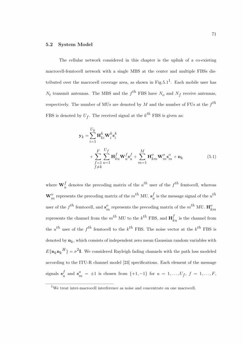
71
5.2 System Model
The cellular network considered in this chapter is the uplink of a co-existing
macrocell-femtocell network with a single MBS at the center and multiple FBSs dis-
tributed over the macrocell coverage area, as shown in Fig.5.11. Each mobile user has
Nt transmit antennas. The MBS and the f th FBS have No and Nf receive antennas,
respectively. The number of MUs are denoted by M and the number of FUs at the f th
FBS is denoted by Uf . The received signal at the kth FBS is given as:
yk =
Uk∑i=1
HkkiWk
iski
+
F∑f=1f =k
Uf∑u=1
HfkuW
fusfu+
M∑m=1
Hokm
Womsom
+ nk (5.1)
where Wfudenotes the precoding matrix of the uth user of the f th femtocell, whereas
Wom
represents the precoding matrix of the mth MU. sfuis the message signal of the uth
user of the f th femtocell, and som
represents the precoding matrix of the mth MU. Hokm
represents the channel from the mth MU to the kth FBS, and Hfku is the channel from
the uth user of the f th femtocell to the kth FBS. The noise vector at the kth FBS is
denoted by nk, which consists of independent zero mean Gaussian random variables with
E{nknkH} = σ2I. We considered Rayleigh fading channels with the path loss modeled
according to the ITU-R channel model [23] specifications. Each element of the message
signals sfu
and som
= ±1 is chosen from {+1,−1} for u = 1, . . . , Uf , f = 1, . . . , F ,
1We treat inter-macrocell interference as noise and concentrate on one macrocell.

72
Fig. 5.1. System model for a single MBS and multiple FBSs
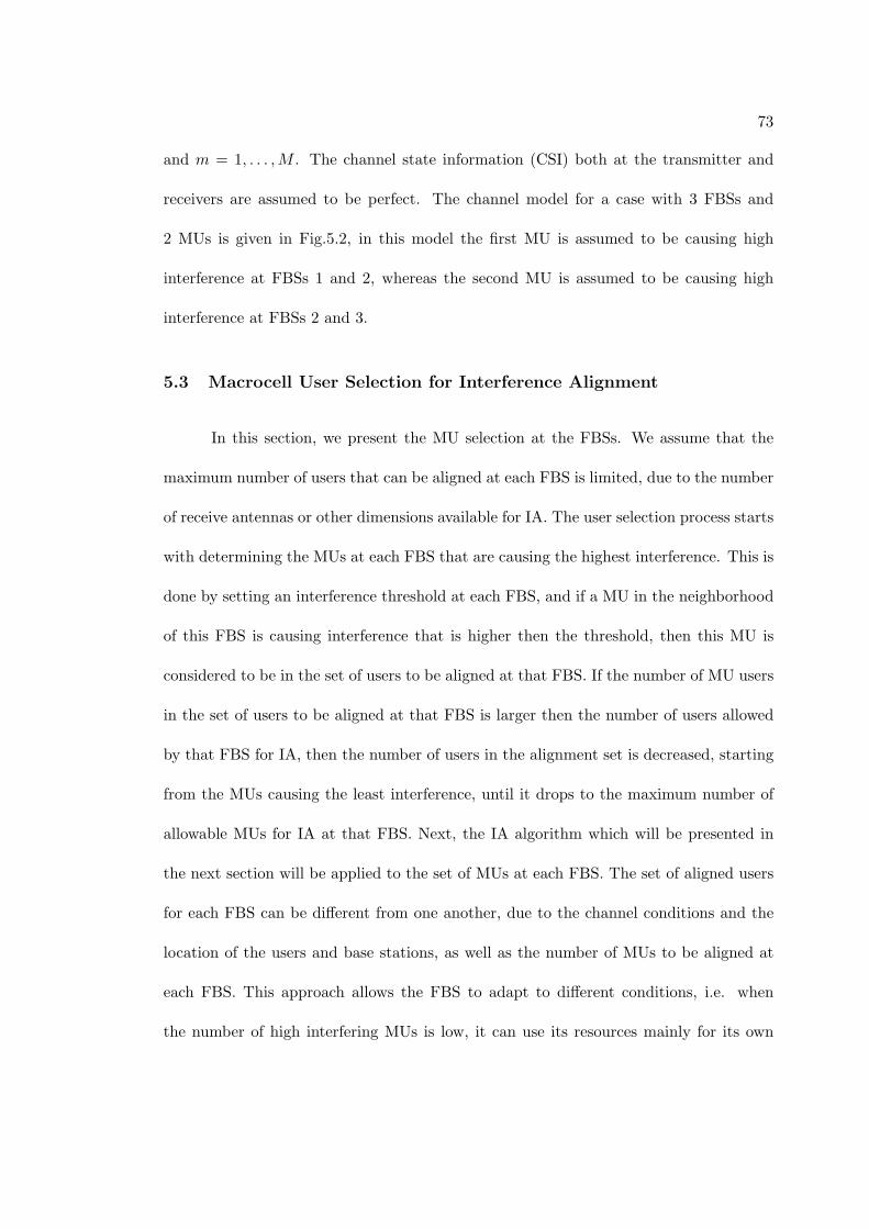
73
and m = 1, . . . ,M . The channel state information (CSI) both at the transmitter and
receivers are assumed to be perfect. The channel model for a case with 3 FBSs and
2 MUs is given in Fig.5.2, in this model the first MU is assumed to be causing high
interference at FBSs 1 and 2, whereas the second MU is assumed to be causing high
interference at FBSs 2 and 3.
5.3 Macrocell User Selection for Interference Alignment
In this section, we present the MU selection at the FBSs. We assume that the
maximum number of users that can be aligned at each FBS is limited, due to the number
of receive antennas or other dimensions available for IA. The user selection process starts
with determining the MUs at each FBS that are causing the highest interference. This is
done by setting an interference threshold at each FBS, and if a MU in the neighborhood
of this FBS is causing interference that is higher then the threshold, then this MU is
considered to be in the set of users to be aligned at that FBS. If the number of MU users
in the set of users to be aligned at that FBS is larger then the number of users allowed
by that FBS for IA, then the number of users in the alignment set is decreased, starting
from the MUs causing the least interference, until it drops to the maximum number of
allowable MUs for IA at that FBS. Next, the IA algorithm which will be presented in
the next section will be applied to the set of MUs at each FBS. The set of aligned users
for each FBS can be different from one another, due to the channel conditions and the
location of the users and base stations, as well as the number of MUs to be aligned at
each FBS. This approach allows the FBS to adapt to different conditions, i.e. when
the number of high interfering MUs is low, it can use its resources mainly for its own
74
Fig. 5.2. Channel Model for 3 FBSs, with 2 FUs in each femtocell and 2 MUs
75
users, achieving high data rates by multiplexing, and when the number of high interferers
increases, it can devote a necessary amount of its resources for aligning these MUs and
to prevent signal degradation for its own users. We denote the set of dominant MU
interferers at the kth FBS as:
Sk = {j ∈ {1, . . . ,M} : tr((HokjWo
j)HHo
kjWo
j) ≥ τk,
|Sk| ≤ nk} ∀k = 1, . . . , F (5.2)
where τk denotes the interference threshold at FBS k, i.e., any MU causing interference
higher than τk will be considered for IA, and nk denotes the maximum number of users
that can be allowed for IA at the kth FBS. The set of FBSs at which the ith MU will
be aligned is given as:
Ti = {j ∈ {1, . . . , F} : i ∈ Sj} ∀i = 1, . . . ,M (5.3)
5.4 Selective Distributed Interference Alignment for Tiered Networks
In order to align the dominant MU interference, we define the interference sub-
spaces at each FBS such that the received signals from the selected MUs at each
FBS will span the subspace specific to that FBS. For this purpose, we define matri-
ces V1,V2, . . . ,VF such that the columns of these matrices define the basis for the
subspaces for the aligned interference at each receiver. That is, each column of HijWoj
can be written as a linear combination of the columns of Vi, ∀j ∈ Si, and ∀i ∈ {1, F}.
The IA condition requires that the received signals from the MU set defined for each

76
FBS span the same subspace, which is given as [11]:
Ho1jWoj ⊂ V1 ∀j ∈ S1
...
HoFj
Woj ⊂ VF ∀j ∈ SF
(5.4)
where X ⊂ Y denotes that the column space of Y spans that of X. Let us denote the
ith column of Vk by vik, or equivalently Vk = [v1
kv2k. . .v
Nkk ] where Nk is the number
of columns in Vk, which should be equal to min(Nr, Nt) and the ith column of Woj as
wioj, i.e. Woj = [w1
ojw2oj
. . .wdkoj ] Then the conditions for IA [11] at FBSs k = 1, . . . F
can be described as follows:
Hokjw1oj
= α1kjv1k+ β1
kjv2k+ . . .+ θ1
kjvNkk , ∀j ∈ Sk
Hkjw2oj
= α2kjv1k+ β2
kjv2k+ . . .+ θ2
kjvNkk , ∀j ∈ Sk
...
Hkjwdjoj = α
djkjv
1k+ β
djkjv
2k+ . . .+ θ
djkjv
Nkk , ∀j ∈ Sk
(5.5)
where αikj
is a constant and the given equations require that all the MUs that are in the
“interference set” of a FBS span the same column space, i.e. the received signals from
those specific MUs are represented by a linear combination of the subspace basis vectors,
scaled by different coefficients, and dj is the number of message bits transmitted by the
jth MU, and the conditions for IA at the remaining FBSs are defined similarly. These

77
conditions can be represented in terms of linear matrix equations as follows:
Hkjwoj = Akjvk, ∀j ∈ Sk, ∀k ∈ {1, F} (5.6)
where Hkj is a block diagonal matrix with dj blocks of Hkj :
Hkj =
Hokj
0 . . . 0
0 Hokj
. . . 0
.... . .
...
0 . . . 0 Hokj
∀j ∈ Sk,∀k ∈ {1, F} (5.7)
where woj =
[w1oj
w2oj
. . . wdjoj
]T∀j ∈ Sk, and vk =
[v1k
v2k
. . . vNkk
]T∀k ∈
{1, F}. The coefficient matrices Akj for ∀j ∈ Sk and k ∈ {1, F} are:
Akj =
α1kj
β1kj
. . . θ1kj
α2kj
β2kj
. . . θ2kj
.... . .
...
αdjkj β
djkj . . . θ
djkj
⊗ INr×Nr
(5.8)
78
where INr×Nrdenotes the (Nr ×Nr) identity matrix, and
Akj =
α1kj
β1kj
. . . θ1kj
α2kj
β2kj
. . . θ2kj
.... . .
...
αdjkj β
djkj . . . θ
djkj
(5.9)
When we follow this procedure for each receiver, the necessary conditions for IA at F
FBSs can be represented as:
Hkjwoj = Akjvk, ∀j ∈ Sk, k ∈ {1, F} (5.10)
The proposed distributed algorithm is as follows:
1) Initialize the matrices V1,V2, . . . ,VF and Akj ∀k = 1, . . . , F and ∀j = 1, . . . ,M .
2) Determine the precoding vectors wo1,wo2, . . . ,woM as:
woj = argminwoj
∑k∈Tj
E{∥Hkjwoj − Akjvk∥2}
s.t. tr((woj)Hwoj) ≤ Pmax (5.11)
where Pmax denotes the maximum total transmit power allowed for the signal transmit-
ted from each mobile user (MU or FU)
3) Normalize the precoding vectors as wok/√
tr(wHokwok).
4) Construct the precoding matrices Wo1,Wo2, . . . ,WoM using the precoding vectors
79
from Step (3).
5) Fix the precoding matrices and determine the vectors v1,v2, . . . ,vF as follows:
vk = argminvk
∑j∈Sk
E{∥Hkjwoj − Akjvk∥2} (5.12)
6) Determine the coefficients Akj for k = 1, . . . , F and j = 1, . . . ,M according to the
following procedure. For a given Hokj,Woj and Vk, construct the following equation:
(Hokjwkoj)T =
[αikj
βikj
. . . θikj
]︸ ︷︷ ︸
(aikj)T
(Vk)T (5.13)
Then aikj
= V†kH
okjwioj, and AT
kj=
[a1kj
a2kj
. . . adjkj
]where V
†k denotes the
pseudo-inverse of the matrix Vk:
V†k = (VH
kVk)
−1VHk
(5.14)
7) Iterate from Step (2) to Step (6) until convergence.
This algorithm is distributed in the sense that, each MU needs to know the channel
gains from itself to the receivers it is interfering, so that it can apply the algorithm and
determine its own precoding vector. Each MU also needs to know Akjvk, ∀k ∈ Tj (for
the jth MU). The normalization in Step (3) is to ensure that the algorithm does not
converge to the solution where all precoders and subspace matrices are null matrices.
80
5.5 Convergence Analysis and Discussion
In this section, we provide convergence analysis of the proposed algorithm in
Section 5.4. We define the total leaked interference from all MUs and FBSs as:
C =
F∑k=1
∑j∈Sk
E{∥Hkjwoj − Akjvk∥2}
=
M∑j=1
∑k∈Tj
E{∥Hkjwoj − Akjvk∥2} (5.15)
When v1, . . . ,vF are fixed, wo1, . . . ,woM are determined according to (5.13), which
decreases the value of (5.20), which then decreases the value of C. Similarly, when
wo1, . . . ,woM are fixed, we determine v1, . . . ,vF using (5.14), which decreases the
value of (19), from which we see that C has also decreased. Thus we conclude that C
is decreased after each iteration, and since C is bounded below by zero, the algorithm
converges. However, due to the non-convex nature of the problem, this algorithm does
not guarantee convergence to the global optimum, and may end up at a local optimum.
Using the KKT conditions for (13) at Step (2), the solution for woj for j =
1, . . . ,M is found as:
woj = (∑k∈Tj
(Hkj)HHkj + λjI)
−1 ∑k∈Tj
HHkjAkjvk (5.16)
81
where λj is calculated such that (woj)Hwoj = Pmax. Next, at Step (5), from the KKT
conditions for (5.14), we determine vk for k = 1, . . . , F as:
vk = (M∑j=1
AHkjAkj)
−1(M∑j=1
AHkjHkjwoj) (5.17)
Using (5.23) and (5.9), we can determine the matrices V1, . . . ,VF .
It is also useful to discuss the reasons for using this model. If we did not specify
the subspaces for each FBS, and still wanted to use a distributed IA algorithm, then the
MUs would have to share information with other MUs (such as channel and coefficient
information), which is not preferred due to the excessive load to mobile users and privacy
issues. If we did not want to share information between users, we would have to use a
centralized algorithm as in [22], but since in the present scheme we are considering
the whole femtocell network instead of a group of FBSs, using a centralized method
would require sending the channel information and the information about the IA sets
for each FBS before each transmission to a centralized processor, and the centralized
processor would solve the IA problem with huge amounts of data, and send back the
determined precoders to the MUs, over the MBS-MUs link. Instead, we are dividing
this single problem into multiple problems that can be solved at each FBS locally, in
parallel with other FBSs, which will save processing and information exchange time. In
the proposed scheme, the information exchange will only take place between the FBSs
and the selected MUs (in the related IA sets). Another benefit is that this algorithm
only uses the precoders for achieving IA, so the decoders can be designed for different
purposes, such as minimizing the sum MSE of the MUs at the MBS, which will reduce
82
the performance degradation of the MUs due to applying IA in favor of FUs. In this
algorithm, each FBS needs to share channel and coefficient information only with the
MUs in its IA set Sk , to create its IA subspace. The MUs only use the information
about the subspaces of the FBSs in their IA set Tj and their channels to those FBSs.
The only constraint for the IA problem is the maximum power constraint, and no other
assumptions (such as unitary matrix assumptions) are made on the precoders/subspaces,
which makes the problem easy to relax into different types, such as an SDP problem,
and add other constraints such as minimum SINR requirements, which can be employed
for improving the QoS of MUs [22].
5.6 Simulation Results
Simulations are done to compare the performance of the FUs for a tiered network
with a single MBS with coverage radius of 500m and 14 FBSs, each with a coverage
radius of 30m. In Fig.5.4, percentages of the bit error rates (BER) of the FUs are given
for a system with 15 interfering MUs, with 4 transmit antennas at the mobile users and 6
receive antennas at the FBSs, the network model used similar to the one in Fig.5.1. The
convergence of the distributed IA algorithm is shown in Fig.5.3. In Fig.5.5, 18 MUs are
distributed over the macrocell coverage area. Each femtocell has 3 FUs, and each user
has 4 transmit antennas, and the FBSs have 7 receive antennas. Noise power is assumed
to be −110dB. Power control at both FBS and MBS is used to compensate for the path
loss. The maximum transmit power of each user is 1W. One bit stream is transmitted
from each user. The comparison of the average BERs of the FUs are given in Fig.5.5.
The user selection scheme is compared with the cooperative scheme, in which the FBSs
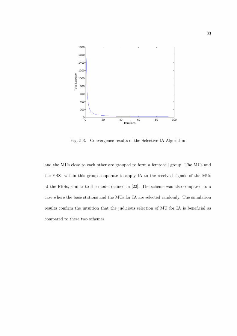
83
0 20 40 60 80 1000
200
400
600
800
1000
1200
1400
1600
1800
Iterations
Tot
al L
eaka
ge
Fig. 5.3. Convergence results of the Selective-IA Algorithm
and the MUs close to each other are grouped to form a femtocell group. The MUs and
the FBSs within this group cooperate to apply IA to the received signals of the MUs
at the FBSs, similar to the model defined in [22]. The scheme was also compared to a
case where the base stations and the MUs for IA are selected randomly. The simulation
results confirm the intuition that the judicious selection of MU for IA is beneficial as
compared to these two schemes.

84
−0.02 0 0.02 0.04 0.06 0.08 0.1 0.12 0.14 0.160
5
10
15
20
25
30
perc
enta
ge o
f the
fem
toce
ll us
ers
BER
Fig. 5.4. Percentage of FUs with a particular BER with the proposed algorithm
14 15 16 17 180
0.01
0.02
0.03
0.04
0.05
0.06
0.07
Number of interfering macrocell users
Ave
rage
BE
R
IA with user selectionIA with femtocell groupingIA with random femtocell selection
Fig. 5.5. Average BER of the femtocell users wrt. number of macrocell interferers

85
Chapter 6
Conclusion
In this thesis, we considered interference management for a two-tier network with
femtocells deployed within a macrocell. In particular, we opted for a design that miti-
gates interference caused by the macrocell users at multiple femtocell uplinks by using
interference alignment (IA).
In this two-tiered network, the interfering macrocell users need to have their
QoS requirements satisfied as well. Therefore, in the third chapter, we put forward an
interference alignment algorithm with individual SINR constraints, in which we used
the SDP approximation to a quadratically constrained quadratic program (QCQP). The
algorithm is applied to mitigate uplink macrocell interference in femtocell networks and
numerical results are provided to demonstrate the advantage of the proposed design over
the case when no interference alignment is done.
In the third chapter, we considered a distributed interference alignment scheme
that is applicable to a generalized tiered network where the interferers from one tier are
distributed over the whole network.
We proposed using user selection at the FBSs combined with a distributed IA
algorithm to eliminate the destructive uplink macrocell interference at the FBSs in the
fourth chapter. The proposed IA algorithm is constructed in such a way that it is
applicable to a tiered network structure (which has significant differences from the K

86
user interference channels for which conventional IA algorithms have been proposed),
and that it mitigates the problems that may arise from using a centralized IA algorithm,
due to backhaul limitations and the excessive load caused on the network.
Future work includes investigation of IA in tiered networks with further reduced
complexity, and the impact of limited/noisy channel state information on the perfor-
mance of IA. For the distributed selective IA algorithm, future work includes improving
the IA algorithm with considering QoS requirements of the MUs, and designing robust
systems with reduced complexity.

87
References
[1] V. Chandrasekhar, J. Andrews, A. Gatherer, ”Femtocell networks: a survey,” IEEE
Commun. Mag., vol.46, no.9, pp.59-67, Sept. 2008.
[2] Picochip, ”The Case For Home Base Stations,” White Paper, Apr. 2007.
[3] S. Verdu, ”Multiuser Detection,” Cambridge Univ. Press, 1998.
[4] R. Yates, ”A framework for uplink power control in cellular radio systems,” IEEE
Journal on Sel. Areas Commun., vol.13, no.7, pp.1341-1348, September 1995.
[5] C. Rose, S. Ulukus, and R. Yates, ”Wireless systems and interference avoidance,”
IEEE Trans. on Wireless Commun., vol.1, no.3, pp.415-428, July 2002.
[6] W. M. Jang, B. R. Vojcic, and R. L. Pickholtz, ”Joint transmitter-receiver opti-
mization in synchronous multiuser communications over multipath channels,” IEEE
Trans. on Commun., vol. 46, pp. 269278, Feb. 1998.
[7] V. R. Cadambe and S. A. Jafar, ”Interference alignment and degrees of freedom
region for the K user interference channel,” IEEE Trans. on Inf. Theory, vol. 54, no.
8, Aug. 2008.
[8] K. S. Gomadam, V. R. Cadambe, and S. A. Jafar, ”Approaching the capacity of
wireless networks through distributed interference alignment,” arXiv, no. 0803.3816,
2008.
88
[9] D.A. Schmidt, C. Shi, R.A. Berry, M.L. Honig, W. Utschick, ”Minimum Mean
Squared Error interference alignment,” 2009 Conference Record of the Forty-Third
Asilomar Conference on Signals, Systems and Computers, vol., no., pp.1106-1110,
1-4 Nov. 2009.
[10] S. W. Peters and R. W Heath, Jr., ”Interference Alignment via Alternating Mini-
mization,” Proc. of IEEE Int. Conf. on Acoustics, Speech, and Signal Processing, pp.
2445 2448, April 2009.
[11] H. Yu, Y. Sung, ”Least Squares Approach to Joint Beam Design for Interference
Alignment in Multiuser Multi-Input Multi-Output Interference Channels,” IEEE
Trans. on Signal Proc., vol.58, no.9, Sept. 2010.
[12] Z. Luo, W. Ma, A.M. So, Y. Ye; S. Zhang, ”Semidefinite Relaxation of Quadratic
Optimization Problems,” IEEE Sig. Proc. Mag., vol.27, no.3, pp.20-34, May 2010.
[13] D. Peaucelle, D. Henrion, Y. Labit, and K. Taitz, ”Users Guide for SeDuMi Interface
1.04,” LAAS-CNRS, Toulouse, 2002.
[14] X. Sun, L. J. Cimini, L. J. Greenstein, D. S. Chant, and J. Kruys, ”Coordinated
zero-forcing beamforming in multipoint MIMO networks for backhaul applications,”
IEEE Military Commun. Conf..
[15] S. Ulukus and R. D. Yates, ”Iterative Construction of Optimum Signature Sequence
Sets in Synchronous CDMA Systems,” IEEE Trans. on Inform. Theory, vol. 47, no.
5, pp. 1989-1998, July 200l.

89
[16] Z. Pan, Kai-Kit Wong, and Tung-Sang Ng, ”Generalized multiuser orthogonal space-
division multiplexing,” IEEE Trans. on Wireless Commun., vol. 3, no. 6, pp. 1969-
1973, Nov. 2004.
[17] Q. H. Spencer, A. L. Swindlehurst, and M. Haardt, ”Zero-forcing methods for down-
link spatial multiplexing in multiuser MIMO channels,” IEEE Trans. on Signal Proc.,
vol. 52, no. 2, pp. 461-471, Feb. 2004.
[18] S. Serbetli, A. Yener, ”Transceiver optimization for multiuser MIMO systems,”
IEEE Trans. on Signal Proc., vol.52, no.1, pp. 214- 226, Jan. 2004.
[19] S. Boyd and L. Vandenberghe, ”Convex Optimization,” Cambridge Univ. Press,
2004.
[20] M. Kojima, L. Tuncel, ”On the Finite Convergence of Successive SDP Relaxation
Methods (1999),” European Journal of Operations Research.
[21] H. Huang, V.K.N. Lau, ”Partial Interference Alignment for K-User MIMO Inter-
ference Channels,” IEEE Trans. on Signal Processing, vol.59, no.10, pp.4900-4908,
Oct. 2011.
[22] B. Guler, A. Yener, ”Interference Alignment for Cooperative MIMO Femtocell Net-
works,” Proc. of IEEE Global Telecom. Conf., Globecom’11, Houston, Texas, Dec.
2011.
[23] ITU-R Recommendation M.1225: ”Guidelines for evaluation of radio transmission
technologies for IMT-2000,” Feb. 1997.
90
[24] S. Ulukus, A. Yener, ”Iterative Transmitter and Receiver Optimization for CDMA
Networks”, IEEE Trans. on Wireless Comm., 3(6), pp.1974-1979, Nov. 2004.
[25] J. Zhang and G. de la Roche ”Femtocells, Technologies and Deployment,” 2010.
[26] L. Zheng and D. N. Tse, ”Packing spheres in the grassmann manifold: A geometric
approach to the non-coherent multiantenna channel,” IEEE Trans. Inform. Theory,
vol. 48, Feb 2002.
[27] O. El Ayach, S. W. Peters, and R. W. Heath, Jr., Feasibility of Interference Align-
ment of Measured MIMO-OFDM Channels, emphIEEE Trans. on Veh. Tech., vol.
59. No. 9. pp. 4309-4321, Nov. 2010.
[28] V. R. Cadambe and S. A. Jafar, ”Interference alignment and degrees of freedom re-
gion for the k user interference channel,” arxiv.org, 2007.arxiv eprint = cs/0707.0323.
[29] P. Xia, V. Chandrasekhar and J. Andrews, Open vs. Closed Access Femtocells in
the Uplink, arXiv:1002.2964v1 [cs.IT] 15 Feb 2010.
Vita
Basak Guler received the B.S degree in electrical and electronics engineering from
Middle East Technical University, Ankara, Turkey, in 2009. Currently, she is pursuing
the Ph.D. degree with the Department of Electrical Engineering, Pennsylvania State
University, University Park. Her research interests include interference management and
cooperation in MIMO femtocell/macrocell networks, interference alignment, multiuser
detection and performance optimization in wireless cellular communication systems.