interference characterization and suppression for
TRANSCRIPT

Interference Characterization and Suppression for
Multiuser Direct-sequence Spread-spectrum
System
by
Mingxi Fan
BARKFPMASSACHUSETSINT-TUtE
OF TECHNOLOGY
JUL 3 1 2002
LIBRARIES
Submitted to the Department of Electrical Engineering and ComputerScience
in partial fulfillment of the requirements for the degree of
Doctor of Philosophy
at the
MASSACHUSETTS INSTITUTE OF TECHNOLOGY
June 2002
© Massachusetts Institute of Technology 2002. All rights reserved.
Author . . . . . r. . . . . . . . . . . . . . . . . . . .. . . . . . . . . . . . . . . . . . . . . . . . . . . .Departmen4 Electrical Engineering and Computer Science
May 3, 2002
Certified by ............ . ...................Kai-Yeung Siu
Associate ProfessorThesis Supervisor
Accepted by ............. ....... ...............Arthur C. Smith
Chairman, Department Committee on Graduate Students

Interference Characterization and Suppression for Multiuser
Direct-sequence Spread-spectrum System
by
Mingxi Fan
Submitted to the Department of Electrical Engineering and Computer Scienceon May 3, 2002, in partial fulfillment of the
requirements for the degree ofDoctor of Philosophy
Abstract
In this thesis we investigate efficient modulation and detection techniques for the up-link (i.e. transmission from mobile to base station) of a DS-CDMA network. Specif-ically, the thesis contains three parts. In the first part, we focus on the mobiletransmitter. In particular, we evaluate and compare the spectral efficiency of twopromising variable rate DS-CDMA transmission techniques, multicode (MCD) andvariable-spreading-gain (VSG), under the presence of multiple-access (user-to-user)interferences (MAI) and multipath interferences. The uniqueness of our study is thatin bit-error-rate evaluation, instead of approximating the interference as Gaussiannoise (which has been done in most of the previous studies), we incorporate bothpower and distribution of interferences into consideration. We show where the Gaus-sian assumption may give misleading answers and how our results in these cases aredifferent from those obtained in the past. In part two and three of the thesis, wefocus on the base station receiver. Specifically, we present effective joint detectiontechniques that have good performance-complexity tradeoff. Part two of the thesis in-troduces a class of novel multistage parallel interference cancellation algorithms basedon stage-by-stage minimum mean-squared error (MMSE) optimization. We show thatthis scheme is capable of achieving significantly better performance than other algo-rithms with similar complexity. Part three of the thesis presents a low-complexitydual-mode multiuser detector that dynamically switches its detection mode betweenthe matched-filter receiver and the decorrelator. We show that this detector is ca-pable of achieving the performance of a decorrelator but with significant savings inprocessing power and complexity.
Thesis Supervisor: Kai-Yeung SiuTitle: Associate Professor
2
Acknowledgments
First, I would like to thank my advisor, Prof. Kai-Yeung (Sunny) Siu for his dedicated
and enlightening guidance during the course of my doctoral study. I have always
enjoyed the many-hour per week discussions (even in late night sometimes) with Prof.
Siu on various research related topics. His inspirational advice not only improved my
analytical skills but also constantly broadened my vision in communications research.
In addition, he also taught me how to effectively express my ideas through both
writing and presentation. Many times, he would go through my paper drafts word
by word to improve my technical writing skills. I really appreciate all his help and
guidance throughout my graduate study at MIT, and I don't think I could have
completed this thesis without him.
Next, my special thanks go to Prof. David Staelin and Prof. Franz Kaertner
for spending many hours of their valuable time to be on my doctoral committee.
Their generous support and insightful suggestions have been a great help and an
integral part in improving the quality of the thesis. It has been a great pleasure and
privilege for me to have them on my thesis committee. In addition, I would also like
to thank many other MIT faculty who have taught me, advised me, and provided me
valuable insights on a wide range of subjects, in particular Prof. Dave Forney (my
master thesis supervisor), Prof. Mildred Dresselhaus (my undergraduate advisor),
Prof. Munther Dahleh (my graduate counselor), Prof. Arthur Smith, Prof. Alan
Willsky, Prof. Gregory Wornell, and Prof. Muriel Medard.
Another special person that I would like to thank is my colleague Thit Minn. Be-
ing a more senior graduate student than me, Thit has always been a great friend and
mentor, especially when I just started exploring CDMA. Thit seems to know every-
thing there is about wireless communications and has a very unique and fundamental
vision on CDMA related technologies. Whenever I talk to him, I not only learn
something new and interesting but also start to think more analytically and critically
about various aspects of my own research. His amazing insights really helped me
to find the key problems and to progress through my research, and I really enjoyed
3

working with him. In fact, results outlined in chapter 2 of the thesis is a joint work
between Thit and myself.
I also would like to thank my friends and colleagues who have supported and
helped me throughout my graduate study. In terms of research, I have always en-
joyed and benefited from technical discussions and/or working with Changqing Zheng,
Albert Chan, Chanvee Chong, Irina Medvedev, Anne Pak, Frank Wang, Boris Bar-
tolome, Nancy Neigus, Michael Parr, Vanu Bose, Andrew Chiu, Alok Shah, Romeo
Velearde, Derek Chan, Alfred Ebrahim, On-Wa Yeung, and many others. I also want
to thank friends (with so many of them and so limited space, I apologize that I cannot
list them one by one) who have supported me mentally and lightened my mood when
I was in deep stress. I would not have made it through MIT without them.
At last, but not the least, my deepest appreciation goes to my family, as home is
always where I can find the most support, comfort, and motivation. I would like to
thank my Dad and Mom for their consistent support, understanding, advice, and love
throughout all these years. I am very lucky to have such special and caring parents.
I would also like to thank my grandparents, in particular my incredible grandmother,
for their love, care and wise advice. I want thank my younger sister, Mingyan, who
is going through MIT undergraduate study right now, for her love and for always
providing her beautifully written poems and funny stories to lighten me up in the
most stressful times. And finally, I want to thank my wife, Jun, for her dearest love
and support. I really appreciate her understanding and patience as I have always
been so busy. Without her quietly taking care of our everything besides my research
even during her pregnancy, there is no way I could have completed this thesis on time.
4

Contents
1 Introduction 11
1.1 Background ... ........... ....... .... ....... ... . 12
1.1.1 DSSS modulation and its application to multiuser communica-
tion networks . . . . . . . . . . . . . . . . . . . . . . . . . . . 12
1.1.2 Why use DS-CDMA for mobile communication? . . . . . . . . 14
1.1.3 DS-CDMA transceiver design for up- and downlink . . . . . . 22
1.2 Summary of thesis contributions . . . . . . . . . . . . . . . . . . . . . 27
1.2.1 Analysis of variable rate DS-CDMA transmission techniques . 28
1.2.2 Multiuser joint-detection . . . . . . . . . . . . . . . . . . . . . 32
1.2.3 Thesis organization . . . . . . . . . . . . . . . . . . . . . . . . 39
2 Error-rate Analysis of Multirate DS-CDMA Transmission Schemes 40
2.1 Background and motivation . . . . . . . . . . . . . . . . . . . . . . . 41
2.2 System m odel . . . . . . . . . . . . . . . . . . . . . . . . . . . . . . . 46
2.3 Error-rate analysis in AWGN channel . . . . . . . . . . . . . . . . . . 48
2.3.1 Results based on Gaussian approximation . . . . . . . . . . . 52
2.3.2 Exact error-rate analysis . . . . . . . . . . . . . . . . . . . . . 54
2.4 Error-rate analysis in flat-fading channel . . . . . . . . . . . . . . . . 58
2.5 Results in multipath fading channel . . . . . . . . . . . . . . . . . . . 63
2.6 Chapter Summary . . . . . . . . . . . . . . . . . . . . . . . . . . . . 83
3 Multistage Interference Cancellation based on MMSE Optimization 84
3.1 Background and motivation . . . . . . . . . . . . . . . . . . . . . . . 85
5
3.2 Existing multistage decision-feedback interference canceller . . . . . . 89
3.2.1 System model . . . . . . . . . . . . . . . . . . . . . . . . . . . 89
3.2.2 Existing methods . . . . . . . . . . . . . . . . . . . . . . . . . 92
3.3 MMSE-based multistage decision-feedback interference cancellation 94
3.3.1 D erivation . . . . . . . . . . . . . . . . . . . . . . . . . . . . . 94
3.3.2 Asymptotic approximation . . . . . . . . . . . . . . . . . . . . 98
3.3.3 Simplified MMSE-based weighted PIC . . . . . . . . . . . . . 99
3.3.4 Practical considerations . . . . . . . . . . . . . . . . . . . . . 102
3.4 Performance analysis of MMSE-based weighted multistage decision-
feedback IC . . . . . . . . . . . . . . . . . . . . . . . . . . . . . . . . 103
3.4.1 Asymptotic error-rate analysis . . . . . . . . . . . . . . . . . . 103
3.4.2 Simulation verification . . . . . . . . . . . . . . . . . . . . . . 106
3.5 Multistage IC with both feedforward and decision-feedback linear pro-
cessing . . . . . . . . . . . . . . . . . . . . . . . . . . . . . . . . . . . 112
3.5.1 Framework of multistage decision-feedback IC with feedforward
m atrix . . . . . . . . . . . . . . . . . . . . . . . . . . . . . . . 112
3.5.2 Multistage IC with MMSE-optimized feedforward and feedback
m atrices . . . . . . . . . . . . . . . . . . . . . . . . . . . . . . 114
3.5.3 Alternative solutions with reduced complexity . . . . . . . . . 118
3.6 Performance of MMSE multistage IC with forward and feedback matrices120
3.6.1 Asymptotic analysis . . . . . . . . . . . . . . . . . . . . . . . 120
3.6.2 Simulation verification . . . . . . . . . . . . . . . . . . . . . . 122
3.7 Chapter summary . . . . . . . . . . . . . . . . . . . . . . . . . . . . . 125
4 A Dual-mode Linear Multiuser Receiver 130
4.1 Motivations and background . . . . . . . . . . . . . . . . . . . . . . . 130
4.2 System m odel . . . . . . . . . . . . . . . . . . . . . . . . . . . . . . . 132
4.3 Architecture of the dual-mode detector . . . . . . . . . . . . . . . . . 136
4.4 Switching criterion . . . . . . . . . . . . . . . . . . . . . . . . . . . . 137
4.5 Performance verification . . . . . . . . . . . . . . . . . . . . . . . . . 147
6

4.6 Chapter summary . . . . . . . . . . . . . . . .
5 Summary and Future Research Directions
5.1 Multirate DS-CDMA transmission techniques
5.1.1 Summ ary . . . . . . . . . . . . . . . .
5.1.2 Potential follow-up studies . . . . . . .
5.2 Multistage parallel interference cancellation
5.2.1 Summary . . . . . . . . . . . . . . . .
5.2.2 Future research possibilities . . . . . .
5.3 Dual-mode linear multiuser detector . . . . . .
5.3.1 Summary . . . . . . . . . . . . . . . .
5.3.2 Future research possibilities . . . . . .
149
150
. . . . . . . . . . 150
. . . . . . . . . . 150
. . . . . . . . . . 151
. . . . . . . . . . 152
. . . . . . . . . . 152
. . . . . . . . . . 152
. . . . . . . . . . 154
. . . . . . . . . . 154
. . . . . . . . . . 154
A Derivation of the weighting matrix for MMSE-based Multistage In-
terference Cancellers 155
B Proof of Theorem 4.1 and 4.2 172
7

List of Figures
1-1 Direct-sequence spread-spectrum modulation illustration . . . . . . . 13
1-2 Frequency assignment in a cellular network, reuse factor = 3 . . . . . 15
1-3 Multiple access technologies in cellular network . . . . . . . . . . . . 17
1-4 RAKE receiver for DS-CDMA systems . . . . . . . . . . . . . . . . . 21
1-5 Standard DS-CDMA transceivers in the downlink . . . . . . . . . . . 23
1-6 Standard DS-CDMA transceivers in the uplink . . . . . . . . . . . . . 24
1-7 The downlink transmitter of a typical DS-CDMA user . . . . . . . . . 25
1-8 Standard DS-CDMA transceivers with joint detection . . . . . . . . . 27
1-9 Variable symbol rate transmission in DS-CDMA: Dual-rate . . . . . . 29
1-10 DS-CDMA mobile transmitter for variable rate transmission . . . . . 30
1-11 Linear joint detector at DS-CDMA base-station receiver . . . . . . . 34
1-12 Successive interference canceller (SIC) at DS-CDMA base-station receiver 35
1-13 Multistage parallel interference cancellation (PIC) at DS-CDMA base-
station receiver . . . . . . . . . . . . . . . . . . . . . . . . . . . . . . 36
1-14 Multistage interference cancellation with feedforward and feedback MAI
cancellation . . . . . . . . . . . . . . . . . . . . . . . . . . . . . . . . 38
2-1 Transmitter of multicode CDMA user . . . . . . . . . . . . . . . . . . 42
2-2 Transmitter of variable spreading-gain CDMA user . . . . . . . . . . 42
2-3 Distribution of MAI seen by the MCD-CDMA HR user in AWGN
channel (N = 64, M = 16, K = 2) . . . . . . . . . . . . . . . . . . . . 58
2-4 Distribution of MAI seen by the VSG-CDMA HR user in AWGN chan-
nel (N = 64, M = 16, K = 2) . . . . . . . . . . . . . . . . . . . . . . 59
8

2-5 The exact error probability of MCD and VSG CDMA users with fixed
phase in AWGN channel as a function of the number of LR users with
N = 64, M = 32 and E/N=l 12dB . . . . . . . . . . . . . . . . . . 60
2-6 BER of MCD and VSG CDMA users in AWGN channel as a function
of the number of LR users with N = 128, M = 32 and Eb/No = 12dB 61
2-7 BER of MCD and VSG CDMA users in Frequency non-selective Rayleigh
fading channel . . . . . . . . . . . . . . . . . . . . . . . . . . . . . . . 64
2-8 VSG Signals in a Multipath Channel . . . . . . . . . . . . . . . . . . 78
2-9 An example of the probability mass function for the correlated MPI of
VSG user in a three-path channel with short delay spread . . . . . . . 80
2-10 BER of MCD and VSG HR users in a two-path Rayleigh fading channel 82
2-11 BER of MCD and VSG HR users in a three-path Rayleigh fading channel 82
3-1 A general multi-stage decision-feedback interference canceller . . . . . 85
3-2 Multi-stage decision-feedback interference canceller in vector form . . 93
3-3 Weighted multistage interference canceller . . . . . . . . . . . . . . . 99
3-4 Error probability convergence based on Gaussian approximation for
WPIC and PIC for system with Loading (a) 3 = 0.5, (b) # = 0.75,
(c)3= 1, (d) #= 1.25, (e) 3=1.5, (f) 3= 2. . . . . . . . . . . . . . 108
3-5 Error probability of weighted PIC vs. the total number of users in
AWGN channel, (a) 1 stage, (b) 2 stages, (c) 5 stages . . . . . . . . . 109
3-6 Error probability of weighted PIC vs. the total number of users in
Rayleigh Flat-Fading channel: (a) 2 stage, (b) 2 stages, (c) 5 stages 110
3-7 Error probability of weighted PIC vs. - in AWGN channel (64 Users)
(a) 1 stage, (b) 2 stages, (c) 5 stages . . . . . . . . . . . . . . . . . 111
3-8 A general multistage interference canceller with feedforward processing 112
3-9 Error probability convergence based on Gaussian approximation for
MMSEMIC and WPIC for systems with loading (a) # = 0.5 and (b)
3 = 0.75 . . . . . . . . . . . . . . . . . . . . . . . . . . . . . . . . . . 123
9

3-10 Error probability convergence based on Gaussian approximation for
MMSEMIC and WPIC for systems with loading (a) 3 = 1.0 and (b)
= 1.25 . . . . . . . . . . . . . . . . . . . . . . . . . . . . . . . . . . 124
3-11 Error probability convergence based on Gaussian approximation for
MMSEMIC and WPIC for systems with loading (a) _ = 1.5, (b) # = 2,
and (c) # = 4 . . . . . . . . . . . . . . . . . . . . . . . . . . . . . . . 126
3-12 Error probability of multistage MMSE IC vs. the total number of users
in AWGN channel: (a) 1 stage, (b) 2 stages, (c) 5 Stages . . . . . . . 127
3-13 Error probability of multistage MMSE IC vs. the total number of users
in flat-fading channel: (a) 1 stage, (b) 2 stages, (c) 5 stages . . . . . . 128
3-14 Error probability of multistage MMSE IC vs. - in AWGN channelNo
(96 Users): (a) 1 stage, (b) 2 stages, (c) 5 stages . . . . . . . . . . . . 129
4-1 Structure of the dynamic dual-mode linear multiuser receiver . . . . . 137
4-2 Comparison of BER between the dual-mode detector, the decorrelator
and the matched filter in a synchronous CDMA system . . . . . . . . 148
4-3 Comparison of BER between the dual-mode detector, the decorrelator
and matched filter in an asynchronous CDMA system . . . . . . . . . 148
A-1 M-PSK signal constellation for M=8 . . . . . . . . . . . . . . . . . . 159
A-2 Geometric representation for M-PSK signal detection in AWGN channel162
A-3 Geometric representation for M-PSK signal detection with MAI in
AW GN channel . . . . . . . . . . . . . . . . . . . . . . . . . . . . . . 163
10

Chapter 1
Introduction
Direct-sequence spread-spectrum (DSSS) modulation technique has been developed
since the 1950's [52]. The initial applications were primarily military related such
as anti-jamming tactical communications, guidance systems, and experimental anti-
multipath systems [59, 69]. With the surge of personal wireless communication sys-
tems in the last one and half decade, DSSS modulation became the foundation of the
physical layer of a widely adopted multiuser wireless communication system known
as the direct-sequence code-division multiple-access (DS-CDMA) system. In this the-
sis, we investigate practical physical-layer modulation and detection techniques for
wireless DS-CDMA system that exhibit robust performance in the presence of inter-
ference. In this chapter, we first provide some essential background information on
DS-CDMA system in section 1.1. Those who are familiar with CDMA can skip over
this section and go to section 1.2, where we describe the problems addressed by the
thesis and summarize our key contributions.
11

1.1 Background
1.1.1 DSSS modulation and its application to multiuser com-
munication networks
Direct-sequence spread-spectrum (DSSS) system is a digital transmission technique
in which the signal occupies a bandwidth in excess of the minimum necessary to
send the information [52]. The bandwidth expansion is accomplished through the
so-called "direct-sequence" spreading modulation, in which a fast, data-independent
code sequence, defined as the spreading code, causes rapid phase transitions in the
data-bearing carrier. Each element of the code sequence is referred to as a chip,
and hence the rate that the spreading code is running at during DSSS modulation is
referred to as the chip rate. The ratio between the chip rate and the data (symbol)
rate (before spreading) is called the processing gain, or the spreading gain, which
measures the amount of bandwidth expansion due to the spreading process. An
illustration of DSSS modulation in both time and frequency domains is illustrated
in figure 1-1. To recover the data of a DSSS user, the receiver normally employs
matched-filter detection that correlates the received signal with the spreading code
in each symbol interval.
In essence, DSSS modulation trades power for bandwidth to combat interferences.
One of the main original motivations of DSSS modulation is to enhance the anti-
jamming capability of a power-limited single-user communication system by providing
the user additional degrees of freedom (or dimensions) after spreading [59]. DSSS
modulation can be viewed as a process that projects a low dimensional (i.e. narrow
frequency-band) data signal onto a high dimensional (i.e. wide frequency-band) signal
space. The total number of dimensions in the system after spreading is typically N
times that before spreading, where N is the processing gain. The philosophy is that
since the user data only occupies one of the N available dimensions, a large N will
give the jammer a hard time to guess where to concentrate the energy of its jamming
signal in the signal space.
12

DSSS b(t) s(t) = b(t)c(t)Modulation
c(t)
Frequency B(f)Domain C(f) S(t)Effect
Time b(t)
Domain c(t)Effect
s(t)
Symbol Interval (T )
Chip Interval (T)
Figure 1-1: Direct-sequence spread-spectrum modulation illustration
Interestingly, these extra dimensions also turn out to be very useful for multi-
plexing subscribers in a multiuser communication system. Theoretically, by assigning
different users different spreading codes, we have mapped each user onto a unique
"code" dimension in the system, which then allows all users to simultaneous transmit
over the same frequency band without significantly interfering each other. The total
number of available dimensions in the system is determined by the spreading gain.
This is exactly the principle behind the well-known direct-sequence code-division
multiple-access (DS-CDMA) system that is widely used in cellular communications
today. In a DS-CDMA system, the data of each user is spread via DSSS modulation
with a user-specific spreading code, which is also used by the receiver to "de-spread"
or demodulate the data for the desired user. The spreading codes are typically de-
signed to have low cross-correlations to minimize interferences between different users.
There are many benefits for using DS-CDMA for mobile radio communication, which
we discuss next.
13

1.1.2 Why use DS-CDMA for mobile communication?
Cellular perspective
Before showing the advantages of using DS-CDMA for mobile communications, we
first introduce briefly the cellular concept, which is the foundation of mobile radio
networks today. Prior to the deployment of cellular networks, the design objective of
early mobile radio system was to achieve a large coverage area by using a single, high
powered transmitter with an antenna mounted on a tall tower [58]. While this indeed
achieves good coverage, the total number of users that the system can accommodate
is extremely limited due to scarcity of the available wireless spectrum, which has to
be shared among all users over a very large geographical region.
The birth of cellular concept was a major breakthrough in solving the spectral-
congestion problem [4, 20]. Instead of having a single, high-powered transmitter, a
cellular network uses many small base stations (cell site) with relatively low transmit
power, each serving a small geographical area (i.e. a cell). Since propagation loss of
the radio signal is proportional to the nth power of the propagation distance, where
n is between 2 and 6 depending on the environment (large for urban area and indoors
and small for rural and light-of-sight connections) [58], the same frequency spectrum
can be reused at distant cells without causing much interference among each other.
The concept of frequency reuse essentially enables the network to serve an unlimited
number of users using finite spectrum, since, if the user population increases beyond
the capacity of the existing cell, a new cell site can always be built to accommodate
the demand.
The frequency reuse pattern of a typical cellular network is illustrated in figure
1-2. The hexagonal cell shape shown in the figure is a conceptual and simplistic model
of the radio coverage for each base station. In a typical cellular network, the overall
available spectrum is divided equally into R disjoint frequency bands, each of which is
reused in every R cells that are far apart enough from each other to minimize intercell
interferences. In figure 1-2, we have R = 3. R is called the frequency reuse factor, and
its value depends on the cell size, distance between the cells, error performance target
14

of the system, and the spectrum-sharing strategy used within each cell. A smaller R
implies a more spectrally efficient system, as well as easier frequency planning.
SPECTRUM ALLOCATION
Spectrum Division
Frequency
Channel Channel ChannelGroup 1 Group 2 Group 3 REUSE FACTOR R = 3
Figure 1-2: Frequency assignment in a cellular network, reuse factor = 3
Within each cell, all users make calls through the base station positioned at the
center of the cell. The transmission link from the base station to user terminals is
called the forward link or the downlink, while communication from user terminals to
the base station is named the reverse link or the uplink. A key design consideration
for the cellular network is how to let users share the available spectrum within each
cell to communicate with the base station in both links. One method is to divide
the total spectrum within the cell into small disjoint bands and assign one frequency
band to each user. This is the well-known frequency-division multiple-access (FDMA)
concept. The first generation (analog) cellular systems are mostly FDMA-based. For
instance, the first U.S. cellular telephone system - Advance Mobile Phone Service
(AMPS) [87], developed by AT&T Bell Labs in the 1970s and first deployed in 1983 in
Chicago, is a FDMA system that assigns a 30 KHz band to each user in both up- and
downlink. The 30 KHz band was later reduced to 10 KHz in the N-AMPS standard
(developed by Motorola) using digital techniques to increase the spectral efficiency
[58]. The first cellular system in Europe, the European Total Access Communication
System (ETACS), developed in the 1980's, was also FDMA-based and in fact almost
15

identical to AMPS, except that the bandwidth for each user is 25 KHz per link
[38]. The advantage of FDMA system is its low cost and simplicity. Its major
drawback, however, is the low spectral efficiency due to large spectral gaps between
adjacent frequency bands [58]. Since the analog bandpass filter used in practical
FDMA systems often does not have a sharp cutoff, these gaps are necessary to prevent
severe cross-talks or adjacent-channel interferences.
With the aid of digital technology, a second spectrum-sharing mechanism, time-
division multiple-access (TDMA), was proposed to increase the spectral efficiency.
In TDMA, the spectrum within a cell is divided into a number of wider frequency
bands, each shared by several users. Within each band, every user is assigned a time
slot and therefore transmits only a fraction of the time. With wider frequency bands,
the waste of bandwidth due to the spectral gaps in TDMA is much less than that
in analog FDMA systems, even though a guard-time needs to be inserted between
time-slots for TDMA systems to avoid interference. Most of the second generation
(digital) cellular networks are TDMA-based. A well-known example is the Global
System for Mobile (GSM) developed in Europe. In GSM, the available frequencies
within a cell is divided into channels of 200 KHz wide, each of which is then used to
accommodate eight full-rate users using eight time-slots, each of 576.9/psec duration
[47]. Another example is the US-TDMA (IS-54 and IS-136), which uses 30 KHz wide
frequency channel to serve three full-rate users, with each user assigned a time-slot
of 6.667ms [14].
In contrast to FDMA and TDMA, in a DS-CDMA system, all users in the cell
spread their signal over the entire available spectrum and transmit at the same time.
What differentiates one user from another, as mentioned before, is the user-specific
spreading code. DS-CDMA is the core technology used in IS-95, a popular second
generation (digital) cellular standard that is mainly developed by Qualcomm and
deployed in North America and parts of Asia including South Korea and China.
In IS-95, the transmitted signal of all users spread over the same 1.25 MHz wide
spectrum in a cell, and the typical spreading gain is 64 [65]. A typical chip rate
used in IS-95 is 1.2288 mega-chips per second (Mcps), which corresponds to a chip
16
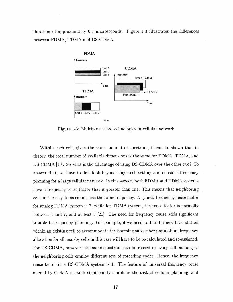
duration of approximately 0.8 microseconds. Figure 1-3 illustrates the differences
between FDMA, TDMA and DS-CDMA.
FDMA
L Frequency
User 3 CDMAUser 2User 1 Frequency
User 3 (Code 3)
Time
TDMA | User 2 (Code 2)
Frequency User 1 (Code 1)
Time
User 1 User 2 User 3
Time
Figure 1-3: Multiple access technologies in cellular network
Within each cell, given the same amount of spectrum, it can be shown that in
theory, the total number of available dimensions is the same for FDMA, TDMA, and
DS-CDMA [10]. So what is the advantage of using DS-CDMA over the other two? To
answer that, we have to first look beyond single-cell setting and consider frequency
planning for a large cellular network. In this aspect, both FDMA and TDMA systems
have a frequency reuse factor that is greater than one. This means that neighboring
cells in these systems cannot use the same frequency. A typical frequency reuse factor
for analog FDMA system is 7, while for TDMA system, the reuse factor is normally
between 4 and 7, and at best 3 [21]. The need for frequency reuse adds significant
trouble to frequency planning. For example, if we need to build a new base station
within an existing cell to accommodate the booming subscriber population, frequency
allocation for all near-by cells in this case will have to be re-calculated and re-assigned.
For DS-CDMA, however, the same spectrum can be reused in every cell, as long as
the neighboring cells employ different sets of spreading codes. Hence, the frequency
reuse factor in a DS-CDMA system is 1. The feature of universal frequency reuse
offered by CDMA network significantly simplifies the task of cellular planning, and
17
this is in fact one of the main reasons why DS-CDMA is chosen as the dominant
technology for the coming third generation (3G) cellular systems, such as wide-band
CDMA (WCDMA) (chip rate 4.096 Mcps) and CDMA2000 (chip rate 3.6864 Mcps)
[2].
In addition to universal frequency reuse, DS-CDMA also has a soft-capacity, which
FDMA and TDMA systems do not have. In both FDMA and TDMA, the maximum
number of users allowed in each cell is hard-limited by the number of available fre-
quency or time slots, respectively. In DS-CDMA, however, the capacity is "soft"
in a sense that the total number of users in the system is only interference-limited.
Users can be admitted into the system as long as the bit-error rate of all in-cell users
are within their performance target. Consequently, any reduction in interferences
immediately gives room to new users. Thus, practical DS-CDMA systems often use
interference reduction schemes, such as sectorization and voice activity detection, to
increase the capacity. For instance, in IS-95 CDMA, each cell is divided into three
120 degree sectors using directional antennas, which, ideally, reduces the user-to-user
interference by a factor of three. In reality, the gain is slightly less due to spillage
between the sectors. In addition, IS-95 uses variable rate voice encoding together
with data-burst puncturing technique such that whenever a user is silent during a
conversation, the silence is detected and nothing is transmitted. In this way, the
low duty cycle of human speech further reduces the user-to-user interferences. It has
been suggested in [21] that with sectorization, voice activity detector, and universal
frequency reuse, a DS-CDMA network is capable of offering a much higher capacity
than FDMA or TDMA based networks.
Radio propagation perspective
In addition to its attractive features in cellular networks, a DS-CDMA system also
exhibits robust performance in a general mobile radio propagation environment at rel-
atively low cost. Unlike wire-line channels that are usually stationary and predictable,
radio channels are extremely random. The signal path between the transmitter and
the receiver in a wireless channel can vary from simple line-of-sight to one that is
18

severely obstructed by buildings, hills and trees. In addition, speed of the user ter-
minal also affects quality of the received signals. Generally, propagation models have
been made to describe the average received signal strength at a given distance from
the transmitter, as well as the variability of the signal strength in close proximity to a
particular location. Propagation models that predict the mean signal strength for an
arbitrary transmitter-receiver separation distance are called large-scale propagation
model, since they characterize signal strength over a large distance (on the order of
tens of kilometers). On the other hand, propagation models that characterize the
rapid fluctuations of the received signal strength over short travel distances or short
time durations are called small-scale or fading model [58, 83]. Communication link
between a mobile subscriber with its designated near-by base station can be typically
described using small-scale fading model, which we briefly describe next.
The small-scale fading effects are mainly created by the existence of time-varying
multiple signal paths between the transmitter and the receiver, or in short, multipath
propagations. In succinct terms, multipath propagation introduces two types of dis-
tortions into the received signal. First, if the bandwidth of the transmitted signal is
larger than the coherent bandwidth [55, 83] of the channel (i.e. the portion of channel
frequency response that is approximately flat), or equivalently, if the symbol interval
is smaller than the delay spread of the channel, the received signal is going to suffer
from inter-symbol interferences (ISI), as multipath components of the the current
symbol may get into other symbol intervals and therefore cause signal smearing. In
such cases, an equalizer is needed to suppress the ISI. Second, due to movements of
the user terminal and the surrounding objects, the multipath components in general
vary with time. These randomly time-varying phases and amplitudes of the differ-
ent multipath components cause fluctuations in received signal strength and thereby
introduces fading. If there is no ISI, then we have frequency-non-selective or flat
fading, in which there is one signal path with time-varying amplitude. This signal
path is in fact the sum of many weak paths that arrive at the receiver in a very short
time interval [83]. If the time offsets between the paths are large enough to cause
ISI, then we have multipath or frequency-selective fading, in which the amplitude of
19

each path varies with time. The amplitude of each faded path is in general modeled
as a Rayleigh random variable [55]. Without proper processing, fading significantly
degrades the quality of the received signal. For example, in a flat fading channel, the
error probability of a single user system only falls off with 1/SNR (where SNR is
the signal-to-noise ratio (SNR)), whereas in an ideal additive white Gaussian noise
(AWGN) channel, the error probability decreases exponentially with increasing SNR
[55].
Many wireless systems need to use equalization techniques to suppress multipath
interferences (ISI). For example, in a TDMA system, equalization is necessary since
the bandwidth of the transmitted signal normally exceeds the coherent bandwidth
of the channel. There are many equalization techniques available, such as maximal
likelihood detection, zero-forcing, MMSE, precoding, and decision feedback [23, 36].
While equalizations can be quite effective, they also add significant complexity at the
receiver. In addition, equalization does not improve the system performance as far as
fading is concerned. To combat fading, diversity techniques are typically employed.
The underlying principle of diversity is to transmit the same information via different
links or channels to the receiver. The motivation is that the more transmission links
we use, the more likely that signal strength on one or more of the links will be
strong. Typical diversity techniques include frequency-diversity, time-diversity, path-
diversity, polarization diversity, and spatial diversity [55]. With diversity, the error
probability in single-user channel now falls off with the Lth power of 1/SNR, where
L is the order of diversity, i.e. the number of transmission links used [55].
In DS-CDMA, the chip rate used for DSSS modulation is typically much higher
than the coherent bandwidth of the channel. Whereas conventional modulation tech-
niques require an equalizer to suppress ISI, the CDMA spreading codes are designed
to provide low correlation (the larger the spreading gain, the lower the correlations)
between successive symbols. Thus multipath propagation in this case merely provides
multiple versions of the transmitted signal at the receiver. Furthermore, if the multi-
path components are delayed by more than one chip duration, they can be resolved
and combined using a RAKE receiver, which provides diversity gain to combat fading.
20

Received Si
from Chan
Delay __, MatchedI Filter
RAKE Finger 2 W1
Delay Matched2 Filter
gal RAKE Finger 2 W2nel .
Delay __,MatchedL Filter
RAKE Finger L WL
Figure 1-4: RAKE receiver for DS-CDMA systems
DecisionStatistic
The RAKE receiver, as shown in figure 1-4, is essentially a diversity receiver
designed specifically for DSSS modulated system, where the diversity is provided
by the observation that with large spreading gain, the multipath components are
approximately uncorrelated from one another when their relative propagation delays
exceed one chip interval [7]. The responsibility of the RAKE receiver is to combine
time-delayed versions of the original signal transmission (i.e. caused by multipath) in
order to improve the signal-to-noise ratio and obtain diversity gain at the receiver. It
accomplishes this task by first using a separate correlation (matched-filter) receiver
(a RAKE finger) for each of the resolvable multipath signals and then combining
the components from all RAKE fingers using a weighting scheme. Typical weighting
schemes used in practice include equal-gain combining (EGC) and maximal ratio
combining (MRC). In EGC, decisions from all fingers are assigned equal weights,
whereas in MRC, the weight assigned to each finger is proportional to its output
SNR, which can be easily measured at the matched-filter output. Subsequently, if M
correlators (i.e. M RAKE fingers) are used to capture the M strongest multipath
components, the order of diversity gain is approximately M. In the current IS-95
standard, the receiver in the downlink uses three RAKE fingers followed by MRC,
21

while the uplink receiver uses four RAKE fingers followed by MRC. With RAKE
receiver, we essentially turn the originally undesirable multipath propagation into
diversity gain to combat fading. Yet, the complexity of RAKE receiver is much less
than most of the equalization techniques. Thus, DSSS is preferable over many other
modulation techniques from the radio propagation perspective because the use of
spreading and RAKE receiver together can lead to robust performance in multipath
fading channels.
1.1.3 DS-CDMA transceiver design for up- and downlink
We now examine and compare the transceiver block diagram for a typical DS-CDMA
user in the downlink (figure 1-5) and the uplink (figure 1-6). In both links, at the
transmitter, the information bits from the source coder (i.e. vocoder or data com-
pressor) of each user first go through channel encoder and interleaver, which offer
protections against random and bursty errors introduced by the channel, respec-
tively. The coded and interleaved symbols are phase modulated and spread by the
user-specific spreading code via DSSS modulation. The output after the spreading is
pulse-shaped and processed by the radio-frequency (RF) front-end before being trans-
mitted to the channel. In the downlink, signals from all users are transmitted by the
base station at the same time, while in the uplink, the user signals are transmitted
by the individual mobile terminals independently and undergo different transmission
delays and channel effects. In both cases, the channel contains signals from all in-cell
users distorted by the channel plus additive background noise that can be modeled as
zero-mean wide-sense stationary Gaussian process. At the receiver, for both up- and
downlink, a conventional DS-CDMA system employs single-user (i.e. matched-filter)
detection followed by RAKE combiner for each user. The detected data symbols are
further processed by the deinterleaver and the channel decoder to recover the original
information bits.
The design considerations for DS-CDMA system are different for the uplink and
the downlink. In the downlink, signals of all in-cell users are transmitted syn-
chronously by the base-station transmitter. This enables us to assign orthogonal
22

User K Encoder Data
Data Interleaver M duar
Usr1 Baseband
User K
Spreading Code- to.
RF
RcvrdChannel
User K Ecoder Data
User k eInterleaver
User K
Spreading CCde
BASE STATION TRANSUTTER
Recovered ChannDeesil Matched Filter R F
and Device adtUser k eieraerRAKE Receiver Baseband
User kSpreading Code
MOBILE RECEIVER FOR USER k
Figure 1-5: Standard DS-CDMA transceivers in the downlink
spreading codes to the subscribers to eliminate user-to-user interferences within each
signal path. For example, in IS-95, orthogonal Walsh-Hadamard codes are used for
spreading in the downlink. However, multipath creates problems for this system.
First, many orthogonal codes, such as Walsh-Hadamard, have poor autocorrelation
properties that makes the user vulnerable to multipath interferences from its own
signal. To alleviate this problem, the spread data of each user is also scrambled by
a long pseudo-random (PN) code with good autocorrelation property before trans-
mission [18]. In practical cellular systems, these PN codes are cell-specific and is
hence the same for all users in a given cell. The downlink transmitter of a standard
DS-CDMA user is shown in figure 1-7. Second, even though orthogonal codes are
used, data of different subscribers may still interfere with each other since the user
signals in different paths may not be orthogonal. To solve this problem, since the
(base-station) transmitter can tolerate significantly more complexity than the mo-
23

User K Mner Data Baseband
Data Interleaver RF
User KSpreading Code
Recoere ChannelUser--K Encoder D aBstobn --- 0- Delay K - h.neData Dne der Modulator o FiK
User KSpreading Code
MOBILE TRANSMITTERS for Users I Through K
Recovered ChannelData Decoder Symbol -Matched Filter
and
User K nd Decision AKE Receiver
User K
Spreading Code to
Recovered Channymbl Matched Filter Bsbn
and - - -and
Usr einterleaver Dcsn AKE Receiver
BASE STATION RECEIVER
Figure 1-6: Standard DS-CDMA transceivers in the uplink
bile receiver, transmitter precoding and adaptation techniques have been proposed to
tune out the user-to-user interferences, which has been addressed in a number of lit-
eratures [29, 79, 82]. The basic approach here is that, assuming a slowly time-varying
channel, the transmitter learns the channel first using pilot sequences and then as-
signs subscribers the appropriate spreading codes that lead to minimal user-to-user
interferences for the given channel.
In the uplink, which is the focus of this thesis, the interference conditions and
design considerations are very different from that in the downlink. Here, since all
user terminals transmit asynchronously to the base station, it is very difficult to find
enough spreading codes that yield low cross-correlations for all users at all possible
time-shifts. In fact, in practical systems such as IS-95, only long PN codes are used
for spreading. Therefore, with only matched-filter detection, the user signals interfere
with each other even in the same signal path. This leads to the well-known near-
24

Informationbits for Convolutional Symbol 19.2 Kb/suser i Encoder: Puncturing
r = 1/2, k = 9 Repetition
Scrambling DataBlock 19.2 Kb/s and 19.2 Kb/s Modulation 19.2 K symbol
Interleaver PC bits MUX (BPSK Map)
Long CodeMask
1.2288 Mcps
RF Front-end
1.2288 Mcps Processing To ChannelI Channel PN Code (i.e baseband
1.2288 Mcps filter, carriermodulation,
Orthogonal Spreading Code amplifier, etc.)(User Specific)
Q Channel PN Code
Cell-specific PN Code Scrambling
Figure 1-7: The downlink transmitter of a typical DS-CDMA user
far problem in CDMA, in which the transmitted signal of a user very close to the
base-station receiver can completely overpower the signal of a far-away user. The
user-to-user interference in the uplink, or the so-called multiple-access interference
(MAI), significantly limits the capacity of a DS-CDMA network.
There are several ways to alleviate MAI in the uplink. The first method is to
make the signal of each user look like white Gaussian noise to the others [21, 73, 78].
Hence, the MAI in this case can be treated as white Gaussian noise, which can be
effectively mitigated using powerful low-rate error-correction codes as in single-user
communication systems. This is in fact the philosophy used in the IS-95 uplink, which
assigns PN spreading codes of long period (241 - 1 chips) for each user and employs
rate 1/3 convolutional code with constraint-length 9 to combat interferences. Similar
approach is used in the uplink of several 3G standards such as wideband CDMA
(WCDMA) and CDMA2000 [2]. The main complexity of this approach resides in the
25

link layer, where stringent power-control mechanism has to be designed and applied
to ensure that the received signal of all users have equal power, since otherwise the
distribution of MAI may no longer look Gaussian.
The second method is to employ strict timing and synchronization control for
the uplink transmission so that the signal of all users arrive at the base station at
approximately the same time. In this way, orthogonal or low-correlation spreading
codes can be employed to alleviate MAI. This technique is proposed in one of the
3G standards called time-division synchronous code-division multiple access (TD-
SCDMA) jointly developed by the Chinese Science Academy and Siemens [66]. In
TD-SCDMA, the maximum time-offset between the received signals of different users
does not exceed 1/4th of a chip interval. Uplink time control is also used in another
potential 3G technology called large area synchronous CDMA (LAS-CDMA) [41], in
which transmission of all users in the uplink are coordinated. The most interesting
aspect about LAS-CDMA is a very special class of spreading codes that is assigned to
the users. This set of codes, originally proposed in [64] and [16], exhibits ideal auto-
and cross-correlation for small time offsets, while the tradeoff is that the number
of codes that show such desirable correlation behavior is limited. The drawback of
this type of solutions in general is that synchronization in the uplink adds significant
amount of overhead and complexity to link layer and network operation.
The third solution is multiuser joint detection, which introduces additional signal
processing after the matched filter to improve the quality of decision statistics. The
justification here is that since the (base-station) receiver can tolerate more complexity
than the mobile transmitter, we can apply signal processing algorithms with moderate
computational complexity to jointly process the received signals of all users after
matched filtering. Unlike single-user (matched-filter) detectors that treat interferences
from other users as background noise, these joint detectors exploit the structure of
correlations between different users and incorporate this additional knowledge into
the detection process. The role of joint detection in a DS-CDMA base-station receiver
is shown in figure 1-8, where the joint detector follows immediately after the bank
of matched filters. The use of multiuser joint detector has many benefits compared
26

to single-user detection. First, it has been shown that systems with joint detectors
typically have a much larger capacity than one with only matched-filter detection
[54, 71, 75, 76, 84]. Second, joint detection relaxes the need for stringent power and
timing control, which takes some processing complexity out of the link and network
layer. The tradeoff here is, however, that effective joint detection algorithms often
introduce significant complexity and cost in the physical layer, which limits its value in
practical implementation. A key contribution of this thesis is to design joint detection
detection techniques that exhibit good performance-complexity tradeoff.
User K En Me Data Baseband
Data Interleaver R F
User KSpreading Code
User K CANne M Mat Baseband Deho y KDa Interl eaver R F
User KSpreading Code
MOBILE TRANSMITTERS for Users I Through K
Recovered ChannelData DcdrSymbol
and DecisionUser I einterleaser
Recovered ChannelData Decoder Symbol
User K and DecisionDeinterleaver
Multiuser
Joint
Detection
Matched Filter
and
RAKE Receiver
UserSpreading Code
Matched Filterand
RAKE Receiver
User KSpreading Code
RF
to
Baseband
BASE STATION RECEIVER
Figure 1-8: Standard DS-CDMA transceivers with joint detection
1.2 Summary of thesis contributions
In this thesis, we investigate efficient modulation and detection schemes for the uplink
of a DS-CDMA system. The first part of the thesis focuses exclusively on modulation
27

and spreading modules at the mobile transmitter. In particular, we evaluate and
compare the spectral-efficiency of two promising variable data (symbol) rate DSSS
modulation techniques, multicode (MCD) and variable-spreading-gain (VSG) CDMA,
under the presence of MAI and multipath interferences. In the second part of the
thesis, we focus on joint detection techniques at the base-station receiver. Specifically,
we introduce two multiuser detectors with good performance-complexity tradeoff.
The first technique is a class of weighted parallel multistage interference cancellation
algorithms based on minimum mean-squared error (MMSE) optimization. The second
technique is a low-complexity dual-mode multiuser detector that dynamically switches
its detection mode between the simple matched-filter receiver and a computationally
intensive linear joint detector. In this section, we describe these topics in more specific
terms and summarize the main contributions of this thesis.
1.2.1 Analysis of variable rate DS-CDMA transmission tech-
niques
Problem
Early DS-CDMA systems are primarily designed for voice applications, in which all
users transmit at the same data rate. Recently, due to the surge of mobile internet
and multimedia applications, the network needs to deliver different types of data to
different users at different symbol rates, which cannot be accomplished using tradi-
tional single-rate systems. This motivates the design of variable data (symbol) rate
DS-CDMA systems.
To minimize the cost at RF front-end, it is desirable to vary the symbol rate
while keeping the chip rate (and thus the spectrum occupation of the transmitted
signal) fixed. For a constant chip-rate DS-CDMA system, there are two promising
variable data-rate transmission techniques. The first technique is called multicode
(MCD) CDMA, in which each user employs more than one spreading codes (code
channels) to transmit in parallel. The second scheme is called variable spreading-
gain (VSG) CDMA, in which each user uses a single spreading code but varies the
28

symbol duration, or equivalently, the spreading gain according to the desired data
rate. Figure 1-9 illustrates the idea of MCD and VSG for a simple DS-CDMA system
with two users of different rates, in which the symbol rate of the high-rate user is twice
that of a low-rate user. In MCD-CDMA, the data symbols of the high-rate user is first
split into parallel low-rate symbol streams, and the symbols in each low-rate stream,
namely a code channel, is spread by a channelization code. Sum of the signals from
all parallel code channels is then transmitted. The channelization codes are chosen
to be orthogonal to minimize interferences between the parallel code channels. Since
the symbol rate in each parallel code channel is the same as that of a low-rate user,
each symbol in MCD is spread with the maximum processing gain. In VSG-CDMA,
the transmitter structure is relatively simpler. The high-rate user increases the data
rate by shortening its symbol interval. Since the chip rate is fixed, shorter symbol
interval leads to reduction in spreading gain. To maintain the same symbol energy
for all transmission rates (so that it is the same as that of a low-rate user or a MCD
user), the transmit power of a VSG high-rate user has to be increased proportionally
with the reduction in spreading gain. Figure 1-10 shows the role of the variable rate
modulation and spreading in the uplink transmitter.
MCD bi 71J7JUser L b2
c2L
VSGUser b b2
c71J7J 2
Low RateUser b
c FF
Figure 1-9: Variable symbol rate transmission in DS-CDMA: Dual-rate
The key question that we are going to answer in this thesis is, for a dual-rate
29

User 1 ne Data Multirate Basebandnde MDuatr Spreading/ - to - Delay 1 Chane
Data Inddeaaeo Modulation R F
User KSpreading Code(s)
User K ARef Data Multirate Baseband Caans-ncde --- a- Spreading,---P to -+-i Delay K -- Chne
Da Interleaver Mdatr Modulation R FK
tUser K
Spreading Code(s)
MOBILE TRANSMITTERS for Users I Through K Using Variable Rate Transmission
Figure 1-10: DS-CDMA mobile transmitter for variable rate transmission
system, given the same error-rate target, which of the two schemes, MCD or VSG,
could lead to a higher capacity in the uplink, or from another perspective, given
the same operating environment, which scheme would yield a lower bit-error rate. In
essence, there are two main issues to be considered. First, since the transmitted signal
of the MCD high-rate user is the summation of the spread signals from all parallel
code channels, it has a much larger peak-to-average power ratio than the signal of
VSG high rate user. It is possible that the high-rate user signal may cause the low-rate
users in MCD-CDMA to have a worse error probability than those in VSG-CDMA.
Second, it has been hypothesized that the error performance of the VSG high-rate
user may be inferior to that of a MCD user due to the loss of spreading gain. Even
though both users have the same symbol energy, it is unsure whether we can trade
transmission power for spreading gain on a one-to-one basis.
The error performance of low-rate users has actually been studied in [25], which
showed through rigorous analysis that low-rate users in both systems exhibit the
same error performance. The error probability of the high-rate users has also been
addressed by a number of literatures [3, 49, 39, 68, 88], but the outcomes are debat-
able due to overly ideal assumptions in the system models. The most questionable
assumption made in majority of these studies is the standard Gaussian approxima-
30

tion, which models all interferences in the system as zero-mean Gaussian random
variables. This approximation may give misleading results for realistic systems, as
will be seen in chapter 2 of the thesis. Another over-simplification often made is that,
in a multipath fading channel, the outputs from different RAKE fingers are assumed
to be independent of each other. In realistic systems, however, unless the spreading
codes have ideal autocorrelation, the RAKE finger outputs are always going to be
correlated, and sometimes the correlation carry a large weight in the final symbol
decision, as will be seen in chapter 2. Therefore, a thorough error-rate analysis for
the high rate user under more reasonable setting is necessary.
Thesis contribution: error-rate analysis for multirate DS-CDMA trans-
mission
In the first part of this thesis, we analyze the uplink error performance for high-rate
users in VSG and MCD systems from a perspective that is different from most of the
previous studies. We assume the use of random user-specific spreading codes at the
transmitter and the use of matched-filter detection followed by RAKE combining at
the receiver. Instead of making Gaussian approximations in error-rate calculation as
have been done in the past, our error analysis shows how both power and distributions
of the interference together affect the quality of the received symbols of the high-
rate user in VSG and MCD system. The outcome of the study not only enhances
fundamental understanding on the performance of MCD- and VSG-CDMA but also
allows us to recommend the "optimal" modulation technique for different channels
and interference environments.
Specifically, assuming both MCD and VSG users have the same operating envi-
ronment and the same symbol energy, we present two sets of results. First, we show
that if the uplink can be modeled as an ideal additive white Gaussian noise (AWGN)
channel, the VSG high-rate user has a better error performance than the MCD high
rate user if the number of low-rate interferers in the system is small. This gap in error
probability is completely contributed by the differences in the distribution of MAI
seen by VSG and MCD user. The underlying reason, intuitively, is that when the
31
number of interferers is small, it is more effective to combat MAI using high trans-
mission power in VSG than spreading in MCD. The same result, however, does not
carry over to flat-fading channel, in which case the error performance of MCD and
VSG users turn out to be identical. This is because the presence of fading smoothes
the distributions of MAI suffered by the VSG user to make it look more like that in
MCD-CDMA.
Our second set of results apply to the case when the uplink is a multipath fading
channel for all users. We show that in this case, if the time offsets between the different
paths are smaller than a fraction of the VSG user's symbol interval (i.e. if the delay
spread of the channel is small), then the MCD high-rate user has a larger SIR than the
VSG user. On the other hand, if the time offsets are larger, then the VSG user would
in general have a better SIR than the MCD user. The difference in the SIR is due to
the correlations between the RAKE finger outputs. A higher SIR, however, does not
necessarily imply a better error probability. While the multipath interferences are
symmetrically distributed for a two-path channel (typical for cellular communication
in rural and suburb areas), in which the SIR gives correct inference about the error
probability, we show that in channels with more than two paths (such as in urban
and indoor environment), the multipath interferences after RAKE combining is not
only non-Gaussian but also asymmetric, in which case a higher interference power
may actually help the corresponding user to achieve a better error rate.
1.2.2 Multiuser joint-detection
Problem
The goal of multiuser joint detectors is to suppress the multiple-access interferences
(MAI), which is particularly serious in the uplink of the DS-CDMA system due to
asynchronous transmission. A joint detector can be viewed as an additional signal
processing block after the matched-filter receiver to enhance the quality of decision
statistics at the input of the symbol-decision device, as shown in figure 1-8. The
optimal joint detector that achieves single-user performance (i.e. the case with no
32
MAI at all) was proposed in [74] using the approach of maximum likelihood sequence
search. Its drawback is that the complexity requirement grows exponentially with the
product of number of in-cell users and the number of symbols per processing frame,
which is too costly to be implemented using today's technology.
Consequently, most of recent researches on joint detection look for suboptimal al-
gorithms that exhibit good performance-complexity tradeoff. These suboptimal tech-
niques can be grossly divided into two categories: linear and non-linear joint detectors.
Linear joint detection algorithms, illustrated in figure 1-11, typically perform a linear
transformation on the matched-filter output of all users to tune out MAI [46]. One
example is the decorrelator, which attempts to completely eliminate the MAI through
linear transformation. It is analogous to the zero-forcing equalizer for ISI cancellation
in single-user communication. This detector is much simpler than the optimal max-
imum likelihood (ML) detector and yet significantly outperforms the matched-filter
receiver at high signal-to-noise ratio. The drawback of this detector, however, is that
the decorrelating linear transformation enhances the background noise. As a result,
when background noise dominates over MAI, i.e. at low signal-to-noise ratios, its
performance can become poorer than the matched filter. Another linear joint detec-
tor is the linear MMSE detector (with similar complexity as the decorrelator), which
is obtained by finding the matrix that minimizes the mean-squared-error between
the transformation output and the original transmitted symbols. The linear MMSE
receiver offers a balance between MAI and background noise suppression and has a
better performance than the decorrelator [54]. The drawback of this scheme is that
it needs accurate estimate for the received amplitudes of all users' signals as well as
the background noise power.
While linear joint detectors are much simpler than the optimal ML detector, their
complexity is still significantly higher than the matched filter due to the necessity for
matrix inversion when calculating the transformation matrix. This gives a complexity
on the order of cubic of the product of number of in-cell users and the number of data
symbols per frame, which is quite large for practical implementation. Even though
MMSE detection can be implemented using linear adaptive filters, such algorithms
33

Matched Filter Symbol UeP- and RAKE -- Decision .User 1
User I User 1 Symbol Estimate
LinearMatched Filter Symbol Ue
-and RAKE -- Decision User 2
Received User 2 Transformation User 2 Symbol Estimate
Baseband
Signal
(Joint Dectector
Matched Filter Symbol User Kand RAKE Decision
User K User K Symbol Estimate
Figure 1-11: Linear joint detector at DS-CDMA base-station receiver
usually diverge for spreading codes with period that spans over many symbols [75].
Yet, the performance of these detectors are no better than the matched filter in low
SNR environment. The need for better performance-complexity tradeoff here prompts
us to propose a dual-mode linear multiuser receiver that is capable of achieving the
performance of decorrelator but with significant reduction in the overall processing
power.
In contrast to linear joint detectors, a general class of non-linear detectors try to
suppress MAI via decision-feedback interference cancellation. The MAI cancellation
can be performed successively or in parallel. In successive interference cancellation
(SIC), as illustrated in figure 1-12, the received user signals are first ranked according
to the received power. The user signal with the highest power is detected first using
matched filter. Its decision is then used to reconstruct its original signal, which is
then subtracted from the total received signal. The second strongest user is then
detected in the same manner. This process continues until all users in the system
are detected. It has been shown [10, 51] that, if the users' received powers are very
different, then the performance of SIC can approach single-user performance bound.
In most practical systems, however, the use of power control make the received power
34

of all users to be roughly the same. In this case, the average error performance of SIC
is quite poor, not to mention that it also gives rise to extremely unequal performance
among users in terms of error rate and latency.
User IReceived Matched Filter Symbol Symbol Estimate
Baseband and RAKE DecisionSignal User I User I
- SignalReconstruction
User 2Matched Filter Symbol Symbol Estimateand RAKE -- Decision
User 2 User 2
- SignalReconstruction
User K
Matched Filter Symbol Symbol Estimateand RAKE WDecision
User K User K
Figure 1-12: Successive interference canceller (SIC) at DS-CDMA base-station re-ceiver
In the presence of power control, as done in practical systems, another type of
nonlinear algorithm - the parallel multistage interference canceller (PIC), has been
shown to perform better than SIC [46]. The conventional PIC, illustrated in figure
1-13, operates in a stage-by-stage manner, with the matched filter being the first stage
[70]. In subsequent stages, the receiver first uses symbol estimates of the previous
stage to reconstruct MAI suffered by all users in the system. These MAI estimates
are canceled from the matched-filter output of all users in parallel. This receiver
performs better much than the matched filter if the user population is not too large,
and unlike in SIC, all users under PIC have the same latency. The drawback with this
type of algorithm, however, is that at every stage, the receiver assumes the symbol
estimates from the previous stage to be completely accurate and hence performs full
MAI cancellation based on these estimates, even though they can be quite poor in
35

reality. If a wrong symbol estimate is used to reconstruct and cancel MAI, the error
will propagation through later stages. This error propagation severely limits the
performance of conventional PIC such that its error rate may not decrease beyond
two stages [75]. In this thesis, we propose a class of parallel multistage interference
cancellation algorithms that alleviates the effect of error propagation and achieves
significantly better performance than the conventional PIC.
ReceivedBasebandSignal
Matched Filterand RAKE
User I
Matched Filterand RAKE
User 2
Matched FilteradRAKEUser K
Parallel
MAI
Cancellatior
User Is-MAI_
User 2'sMAI
User K'sMAI
Symbol User IDecision Symbol Estimate,
User I Stage
Symbol User 2Decision Symbol Estimate,
User 2 Stage i
S ymbol User K
Decis.on Symbol Estimate,Ueser K Stage
MAI
Estimation
andReconstruc
User ISymbol Estimate,
Stage i
SyUser 2Symbol Estimate,* Stagesi
User K-+-- Symbol Estimate,
Stage i
Figure 1-13: Multistage parallel interference cancellation (PIC) at DS-CDMA base-station receiver
Thesis contribution in non-linear joint detection: MMSE-based multistage
parallel interference canceller
Another key contribution of this thesis is the design of effective parallel multistage
interference cancellation algorithms for DS-CDMA base-station receiver. The design
objective here is to maximize the spectral and energy efficiency of the system under
a set of given complexity constraints. We show that, by exploiting the reliability of
previous symbol estimates used in MAI reconstruction, the proposed receiver signifi-
cantly outperforms existing joint detectors that are on the same order of complexity.
36

Specifically, we introduce two algorithms that are differentiated by their com-
putational complexity constraints. The first algorithm is relatively simple, and its
complexity is on the same order of that for conventional PIC. This detector is derived
by finding the optimal MAI reconstruction and cancellation process that minimizes
the mean-squared cancellation error (MSE) at each stage. We show that this MMSE
solution can be viewed as a conventional PIC scaled by a weighting matrix. The exact
expression of the weighting matrix is derived for M-ary phase-shift-keying (M-PSK)
modulated data symbols (typically M = 2 for BPSK and M = 4 for QPSK). We
show that the parameters of the weighting matrix depend mainly on the error prob-
abilities of the symbol estimates in the previous stage, which can be readily obtained
via pilot sequences or signal-to-interference ratio (SIR) approximation using today's
technology. The proposed receiver demonstrates drastically better error performance
over the conventional PIC, particularly for a large system, i.e. a system where the
ratio of the number of users to the spreading gain is large.
Compared to the first method, our second algorithm has a higher complexity,
which is on the order of that for linear joint detection, as it requires one matrix inver-
sion for each stage. In this detector, we suppress the MAI not only via the feedback
MAI reconstruction and cancellation unit but also introduces a preprocessing (feed-
forward) unit that performs a linear transformation to the matched-filter outputs to
tune out part of the MAI even before the feedback cancellation. This leads to the
standard framework of decision-feedback multiuser detector with feedforward pro-
cessing [75], as shown in figure 1-14. In this thesis, we find the optimal feedforward
and feedback unit that jointly minimizes the MSE of symbol decisions at each stage.
The key element here is again the use of a weighting matrix that is derived in the
first algorithm to measure the reliability of symbol estimates in the previous stage.
We show that while the complexity of this receiver is on the order of that for linear
joint detectors, its error performance is not only superior to linear detectors but is
also capable of approaching the optimal (single-user) performance bound in just a
few iterations. In simulation, it also shows essential immunity to MAI for multiuser
DS-CDMA system employing random spreading codes as long as the load is less than
37

Matched Filterand RAKE
Matched Filter
and RAKE
User 2
Matched Filter--- and RAKE --
Linear
Pre-Processing
Parallel
MAI
Cancellatior
User Il'sMAI
User 2'sMAI
User K'sMAI
Symbol User IDecision Symbol Estimate,
User I Stage i
SymbolUser 2EDec.isio Symol Estimate,
S- IUser 2 Stage
Symbol User KDecision Symbol Estimate,
User K Stage
MAI
Estimation
andReconstruc
User I- Symbol Estimate,
Stagei
User 2+ Symbol Estimate,Stage
User KSymbol Estimate,
Stage i
Figure 1-14: Multistage interference cancellation with feedforward and feedback MAIcancellation
Thesis contribution in linear joint detection: A dual-mode linear multiuser
detector
In the third part of the thesis, we study linear joint detection techniques for DS-
CDMA receiver. The design objective here is to minimize the complexity and pro-
cessing power while meeting the performance target (such as bit-error-rate target) for
each user. By exploring the differences in signal-to-interference ration (SIR) for the
decorrelator and the matched filter, we derive a dual-mode detector that is capable
of achieving the spectral-efficiency of the decorrelator detector with significantly less
processing power and complexity.
The architecture of the dual-mode detector is quite simple: the receiver dynami-
cally switches its mode between decorrelator and matched-filter detection. The basic
philosophy of this detector is that since decorrelator outperforms the simple matched-
filter detection only in the case when MAI dominates over background interferences,
38
100%.
ReceivedBasebandSignal

and yet it yields a much higher computational complexity, the decorrelating opera-
tion should be performed only when the background interference is weak relative to
MAI. In practical cellular communications, the background interference includes not
only thermal noise but also interferences from users in neighboring cells, which can be
quite strong sometimes. Consequently, in a system where this dual-mode detection
algorithm is implemented in firmware, such as on a DSP chip, skipping the decorrela-
tor operation when necessary is capable of leading to significant savings in processing
power, which allows more effective and dynamic resource sharing at the base-station
receiver.
The key to this dual-mode detector is the decision criterion as when decorrelator
detection should be performed. We derive this decision module based on our analysis
and assessment of the amount of noise enhancement introduced by the decorrelator
transformation. If our noise-enhancement measure is higher than the MAI suffered by
most users, then the decorrelator operation will not be performed. The performance
of this dual-mode detector is verified via simulation, in which we show that, while
the decorrelating operation is performed less than half of the time, the bit-error rate
of this receiver is very close of that of the full decorrelator.
1.2.3 Thesis organization
The rest of the thesis is organized as follows. Chapter 2 presents the bit-error-rate
analysis for multicode and variable spreading-gain DS-CDMA modulation techniques.
Chapter 3 introduces the two aforementioned multistage interference cancellation
techniques that aim to optimize the spectral efficiency of the system while satisfying
the complexity constraints. Chapter 4 introduces the dual-mode multiuser receiver
that saves processing power while achieving the desired BER target. Concluding
remarks and future research directions are given in chapter 5.
39
Chapter 2
Error-rate Analysis of Multirate
DS-CDMA Transmission Schemes
In this chapter, we analyze and compare the error performance of a dual-rate DS-
CDMA system using multicode (MCD) and variable-spreading gain (VSG) modula-
tion in the uplink. The uniqueness of our study is that in bit-error-rate evaluation,
instead of approximating the interferences as Gaussian noise (which has been done in
most of the previous studies), we incorporate both power and distribution of interfer-
ences into consideration. Specifically, we present two sets of results. First, we show
that in an ideal AWGN channel, the error rate of the VSG high-rate user is better
than that of the MCD high rate user if the number of low rate interferers is smaller
than a specific threshold. Otherwise, both systems achieve similar error performance.
Second, we show that for RAKE reception in a multipath fading channel, the VSG
user suffers from a larger interference power than the MCD user if the channel de-
lay spread is small. The reverse is true for a large delay spread. Furthermore, we
show that having a larger interference power in this case may lead a better error
performance due to the asymmetric distribution of multipath interferences.
40

2.1 Background and motivation
Early mobile communication networks are primarily designed to provide voice-based
services, in which all users transmit at the same data rate. Recently, with the surge
of demand for internet applications, a mobile user also desires to communicate using
other types of information such as short message, video and multimedia contents.
Consequently, traditional modulation method in which all users operate at the same
data rate no longer suffices. In order to deliver different quality-of-services (QoS)
for the individual customers, efficient variable data-rate transmission techniques are
necessary.
In this chapter, we study the performance of variable data-rate modulation tech-
niques in the uplink of DS-CDMA system. Due to wide spectrum occupation of the
CDMA signal, it is desirable for a DS-CDMA system to vary data (symbol) rate while
fixing the chip rate so that spectrum occupation of the transmitted signal is constant.
Under this constraint, there are two promising variable data-rate DS-CDMA modu-
lation techniques. In the first method, the user changes the symbol rate by varying
the spreading gain (and thus the symbol interval). The transmit power is changed
proportionally at the same time so that the user maintains the same symbol energy
for all possible data rates. This is known as variable-spreading gain CDMA (VSG-
CDMA) [28] (since spreading gain and transmit power vary with data rate). Under
the second technique, a user maintains the maximum spreading gain at all times and
increases its data rate by using more than one parallel code channels for simultane-
ous transmission. In such a system, a high-rate data stream is split into a number
of parallel low-rate streams, each operating at the lowest (basic) symbol rate. Data
streams in different parallel channels are spread using different orthogonal spreading
(channelization) codes to avoid excessive self-interferences. The spread signal from all
parallel channels are summed and scrambled by a user-specific signature code before
transmission. This scheme is known as multicode CDMA (MCD-CDMA) [27]. The
transmitter structure for MCD- and VSG-CDMA systems are shown in figures 2-1
and 2-2, respectively.
41

Cl
Channel 1
Channel 2
C 2
Channel M
C M
rJ)
User SignatureCode (PN)
Pulse RFShaping U
0
(RC = N*Rb chip/s)
Figure 2-1: Transmitter of multicode CDMA user
User Signature
Code (PN)
User Data Pulse Power(Rate = M*R bb/s) Shaping Comp
(Rate = N*Rbchip/s)
Figure 2-2: Transmitter of variable spreading-gain CDMA user
An important question to ask is which of the two schemes is more suitable for
practical systems. The answer depends on a wide range of considerations. In terms
of data-rate flexibility, MCD offers more choices of transmission rates than VSG
does. While MCD can offer rates that are integer multiples of the basic (minimum)
rate, VSG can only employ spreading gains that are integer divisors of the maximum
spreading gain [48]. In terms of link-layer complexity, VSG requires more intensive
processing than MCD due to a problem known as code blocking in the downlink
[45]. On the other hand, from the physical-layer perspective, VSG shows a significant
edge over MCD in terms of implementation and operating cost. While the physical
42
-U
User Data(M*Rb b/s)

layer of a VSG system does not vary significantly from that of a single-rate DS-
CDMA system, a MCD system requires noticeably more expensive hardware because
its receiver architecture is non-scalable (the number of RAKE receivers must be equal
to the maximum number of code channels available at the transmitter [48]). Also,
the transmitted signal from MCD-CDMA has a multi-level envelope because it is the
summation over all parallel code channels. This leads to very high peak-to-average
power ratio and requires the use of power-inefficient linear amplifier [11, 80].
Aside from the aforementioned practical tradeoffs, the key performance measure
of our interest is the spectral efficiency, which determines the capacity (i.e. aggregate
data rate of all users) that the system can support at a pre-determined target error
rate. Or equivalently, we would like to compare the bit-error rate of the two systems
under the same operating conditions. We focus on the uplink, i.e. the transmission
link from mobile subscribers to the base-station, where the user-to-user interference,
or the so-called multiple-access interference (MAI) in this case is more severe than
that in the down-link.
We consider a standard dual-rate system, in which there is one high-rate (HR)
user and multiple low-rate (LR) users. For this system, there are two issues to be
considered. First, it would be interesting to study the impact of the HR user on
LR users, since it has been hypothesized that LR users in MCD-CDMA may have a
worse error performance than those in VSG-CDMA because the transmitted signal
of a MCD HR user has a much larger peak amplitude than that of the VSG user [25].
Second, we would like to compare the error performance of VSG and MCD HR users.
A number of literatures [5, 35, 39] raised concern that the VSG HR user may have a
worse performance than the MCD user due to the loss of spreading gain. Even though
the VSG user increases its transmission power proportionally with the reduction in
spreading gain, it is unsure whether we can trade spreading gain with transmission
power on an equal basis. In this chapter, we focus only on the error performance of
the HR user and treat LR users as interferers, since the reverse scenario where LR
users are the target and HR user is the interferer has been clearly addressed in [25]
(which showed that LR users have identical error performance under both VSG and
43

MCD HR users).
Specifically, we address two fundamental issues. First, we consider a frequency
non-selective channel, in which the MAI from LR users is the dominant interference.
The key question here is whether it is more effective to combat MAI using a larger
spreading gain (as in MCD) or higher transmission power (as in VSG), as it is unsure
whether we can trade spreading gain for transmission power on a one-to-one basis.
Early work in [49] claimed that MCD and VSG HR users achieve the same error
performance in this case. This result, however, is based on an analytical model that
approximates the MAI as additive white Gaussian noise, which clearly does not apply
to many practical cases [40]. The results from [3] and [68], on the other hand, favored
VSG over MCD. They approximated MAI as Gaussian noise as well and in addition
assumed the parallel code channels of the MCD user to be non-orthogonal, in which
case the VSG user actually has a larger signal-to-interference ratio (SIR) than the
MCD user.
Here, instead of employing the classical Gaussian approximation as have been
done in previous studies, we incorporate not only power but also distribution of the
interferences into error performance evaluation. We show that in an ideal additive
white Gaussian noise (AWGN) channel, the VSG HR user achieves a significantly
lower error probability than the MCD HR user if the number of LR interferers in the
system is small, even though both have the same SIR. This gap in error probability is
completely due to differences in the distribution of MAI seen by the VSG and MCD
HR user. The same result, however, does not carry over to flat-fading channel, in
which case the error performances of MCD and VSG users turn out to be identical.
This is because the presence of fading smoothes the distributions of MAIs suffered by
both VSG and MCD user to make them look more alike.
The second issue that we address applies to transmission over multipath fading
channels, in which RAKE receivers are used as a diversity technique to combat fad-
ing [69]. Analyses for conventional CDMA users (i.e. LR users) usually ignore the
multipath interferences (MPI) at the RAKE finger outputs because they are typically
small when the spreading gain is large [55][9]. Here, however, both MCD and VSG
44
HR users may experience strong MPI for different reasons. For the MCD user, the
MPI is a sum of interferences contributed by cross-correlation among its parallel code
channels, while for the VSG user, the MPI is contributed by the partial autocorrela-
tion of its signature code [56], which normally increases with the amount of reduction
in spreading gain. The key question here is which type of interferences has a worse im-
pact under the use of RAKE receivers. This topic has been investigated by a number
of literatures [49][88][39][35]. It has been claimed in [49] that both types of inter-
ferences have the same effect, under the assumption that interferences from different
RAKE fingers are mutually independent. Recent work in [88], however, questioned
the validity of this assumption and suggested that the RAKE finger outputs of a VSG
HR user are strongly correlated, which leads to a much higher error probability than
that of the MCD HR user. Both studies model MPIs as a Gaussian random variables
conditioned on path delays, amplitudes, and phase offsets.
We investigate this issue by incorporating both power and distribution of MPI into
consideration. In terms of interference power, we show that if all pair-wise path time-
offsets are smaller than a fraction of the VSG user's symbol interval (i.e. if the delay
spread of the channel is small), the MCD HR user has a larger SIR than the VSG user.
On the other hand, if the time offsets are larger, then the VSG user would in general
have a better SIR than the MCD user. The difference in the SIR is due to correlations
between the RAKE finger outputs. A higher SIR, however, does not necessarily imply
a lower error probability. We show an example for channels with more than two paths
(such as in urban and indoor environment), in which the multipath interferences after
RAKE combining is not only non-Gaussian but also asymmetric. In this case, a higher
interference power may actually help the corresponding user to achieve a lower error
rate.
The rest of the chapter is developed as follows. In section 2, we develop a basic
model to analyze MCD- and VSG-CDMA systems. We examine the error perfor-
mance of both systems in AWGN channel and flat fading channel in sections 3 and 4,
respectively. In section 5, we present analytical results for multipath fading channels.
Chapter summary is given in section 6.
45
2.2 System model
We assume a dual-rate system with one high-rate (HR) user and K low-rate (LR)
users, where the data symbol of all users are binary phase-shift-keying (BPSK) mod-
ulated. We also assume that users transmit asynchronously and that signature codes
of all users are independently and randomly generated, with each chip being 1 or -1
with equal probability. All LR users operate at the basic rate, while the HR user
transmits at M times the rate of LR users. Mathematically, the baseband signal
transmitted by the MCD HR user can be expressed as
M
sMCD(t) (2.1)m=1
where
00
b(h) (t) = b (h(i)rectb(t - iT),i=-o
oo N
c(h (t) = d () j)p(h)(iN + j)o(t iT- jTc),i=-oo j=1
where P is the transmit power per code channel; b$()(i) E {1, -1} is the ith data
symbol in the mth parallel channel; d$(j) E {1, --1} is the jth chip of the orthogonal
spreading code for the mth channel; p(h)(j) E {1, -1} is the jth chip of the HR
user's signature code; T and Tc are the symbol and chip interval, respectively, where
Tb = NTc with N being the maximum spreading gain; rectb(t) is a unit-amplitude
rectangular pulse from t = 0 to t = T; 4'(t) is the normalized time-limited chip
waveform such that ft3| P(t)l 2dt = y (and f I c, (t)|2 = 1 for all m).
Similarly, the transmitted signal of the VSG-CDMA HR user can be expressed as
sVSG(t) = MPb(h)(t)c(h)(t), (2.2)
46

where
() b(h)(i) Tect(t-i ), c(h) t)- p(h)(j)4,(t -T)-0 j=-00
where b(h) (i) is the ith data symbol of the VSG user; Tect(t) is a unit-amplitude
rectangular pulse from t = 0 to t =TI; p's and 4'(t) are the same as those specified for
the MCD user. Note that the symbol interval of the VSG user is shortened by a factor
of M compared to the MCD and the LR user. Its transmission power is increased by
M times to compensate for the loss of spreading gain so that f,=i MO c(h)( 2d 1.
As a side note, the signal of the kth LR user (k E [1, K]) can be expressed as
s -(t) = v/Pbf (t)c4 (t) cos w't, (2.3)
where
00 00
b (t) = b (i)rectb(t - iT), cf (t1) = p(t - jTc),i=-00 j=-00
where b (i) E {-1, 1} and p)(j) E {-1, 1} are the ith data symbol and the jth chip
of the signature code for the kth LR user, respectively.
Assuming the channel is wide-sense-stationary (WSS) and perturbed by additive
white Gaussian noise (AWGN), the composite received signal at baseband is
K Q(k)
r(t) = A7,qeic/,k sk(t - Tk,q) + r(t) (2.4)k=O q=1
where n(t) is the background interference and can be modeled as a white Gaussian
process with one-sided spectral density of No; Ak,q's, Okq's, Tk,q's and Q(k) are the
received amplitude, phase, and propagation delay of the qth signal path and the
number of resolvable paths for the kth user, respectively; The path gains and delays
vary according to the channel model. For notational convenience, we denote user 0
as the HR user.
47

We assume a receiver that employs matched-filter detection followed by coherent
RAKE combining. The decision statistic for the ith bit in the mth code channel of a
MCD HR user can then be expressed as
Q(O)
y -= Re{ wqy$,q(i)}, (2.5)q=1
where wq is the weight for the qth signal path in RAKE combining; For equal-gain
combining, signal from all paths are weighed equally, i.e. wq = 1, while in maxi-
mal ratio combining, the weights for each path is proportional to its received signal
strength, i.e. wq= |Aq1; y$,q(i) is the matched filter output at the qth RAKE finger
such that
(i+1)Tb+TO,q
-m~ IiTb+To"q r (t)c~( C TQq)ei-jOO~qdt, (2.6)
Similarly, the decision statistic for the ith bit of the VSG user can be found as
Q(O)y(h)(i =h (2{ 7)
q=1
where y!h)(i) is the matched-filter output from its qth RAKE finger such that
/ (i+1) $+O,q-h) i+1 q r (t)c(h) (t -- T0 ,q e j' dt. (2-8)
Yq a ~+ -o, q Oq
2.3 Error-rate analysis in AWGN channel
We first analyze the error performance of the HR user in a stationary AWGN channel.
The composite received signal in this case can be simplified to
K
r(t) = ( Sk(t - Tk)ejlk + n(t). (2.9)k=O
Without loss of generality, we make the following assumptions to simplify the analysis:
48

1. Transmission delay and phase offset of the HR user is the point of reference, i.e.
To = 0 and qo = 0.
2. Signals of all LR users arrive after the HR user, i.e. Tk > 0 for k = 1, 2, ... K;
Phase offsets of the LR users, i.e the #k's, are independent and identically
distributed (i.i.d.) random variables uniformly distributed between -7r and 7F.
3. The system is symbol-asynchronous but chip-synchronous. This means that
transmission delays of LR users are integer multiples of chip intervals, i.e. Tk
6k * Tc, where 6 k E Z+.
The matched-filter output for the ith symbol in the mth code channel of the MCD
HR user can then be expressed as
K
yPb() = b'$ (i) + (cos0)(b pk=1
+ bk(i - 1)p, (i)) + ni (2.10)K
VT (b (h)(i) + E Xm,k (j) cos qk + )i
where ni is the background noise term modeled as a zero-mean Gaussian random
variable with variance NO; The summation term contains MAI from all LR users due
to cross-correlation of the spreading (signature) sequences. The correlation terms in
the MAI for k : 0 are defined as
liTbPk i) = c m(t )ck (t - Tk) dt (2.11)J(i-1)Tb+|Tk
|(i-1)Tb+-kp( = i =(t)ck(t - Tk dt (2.12)J (i- 1)Tb
49

Due to chip synchronism, we can further express the correlation terms as
P~?k(2)
pt7:?(i)
0) N--Sk- bki) j d(h)(j ( )(iN + j)p~' (iN + + 'k)
j= 1
.N Z d(h) (j)p(h)(iN + j)pf (iN + j + 6k)
where k is the energy of each chip, i.e. f | (t) 2dt - . Since the signature code
of each user, i.e. the p's, are random, independently and equally likely to be 1 or -1,
we can model the sum of the correlation terms as a "symmetric binomial" random
variable such that
N
Xm,k(i) = P$,(k) -p + i = Zmkmn(j)j= 1
(2.15)
where Xm,k (j)'s are independent and identically distributed (i.i.d.) random variables
with the following "symmetric Bernoulli" distribution:
Pxm,k(j)(X) =
0.5
0.5
0
if x = - N
ifx = }N
Otherwise.
Xm,k (i)'s are therefore i.i.d. random variables with "symmetric-binomial" distribution
as follows:
Pxm,k(j)(x) = B(1, x) (2.17)
where B(r, x) is the "symmetric binomial function" denoted as
if X c{-r I- r 2-- r, .. ,Tr-k-Lr}B(r, x) =
0
Nr
Nx Nr Nr (2.18)
Otherwise.
50
(2.13)
(2.14)
(2.16)

Similarly, the matched-filter output for the ith symbol of the VSG user can be
expressed as
K
yVk(i) cosk ) + rVSG (2.19)k=1
where the factor - results from shortened symbol interval and power compensation,
i.e. the amplitude of the signal component of matched-filter output is
c(h) t)2 2- Z V) (t)12
N j(2.20)M N/ I
N Mj=1
For similar reason, the noise term niySG is now a zero-mean Gaussian random variable
with variance O. Vk(i) cos #k is the MAI from the kth LR user such that
iTb
Vk(i) J c(h)(t)c(')(t - Tk)dt. (2.21)(i-1)M
Due to random spreading, using similar approach as in MCD analysis, we can model
Vk(i) as
N/M
Vk(i) = : 1X,O( 3 ) (2.22)j=1
where Xk,o(j)'s are i.i.d. symmetric Bernoulli random variable with the same distri-
bution as Xm,k(J). Note that due to the shortened symbol interval, the number of
terms in the summation is a factor of M less than in the case of MCD. Consequently,
the distribution of Vk(i) can be found as:
Pvk(i)(v) = B( ,v) (2.23)
51

2.3.1 Results based on Gaussian approximation
The simplest method to obtain the error probability is via the standard Gaussian ap-
proximation (GA) [17, 49], which assumes the sum of all interferences experienced by
the desired user to be a Gaussian random variable. In this case, the error probability
of the MCD HR user is
PeMCD = Q(VSIRMCD). (2.24)
where Q(x) equals to one minus the cumulative distribution function of a zero-mean,
unit-variance Gaussian random variable such that [17]
Q(x ) = e-dt (2.25)
Note that the error probability here is a function of only the MCD user's signal-to-
interference ratio (SIRMCD), which can be found as
SIRMCD PPVar(jk_1 Xm,k(i) cos qk) - N
1
K E[Xmk ()COS2 _L...k=1Lmk 'kJ +P (226I12 (2.26)
E E[X,k(i)]E[cos 2 o] +1
where the last step is obtained from
E[X2,k] = ZE[X2,m(j)] = (2.27)j=1
E[cos 2 Ok] = cos 2 qdq = - . (2.28)_-,7 27r 2
A more accurate method to evaluate the error probability is the improved Gaussian
approximation (IGA) [40], the basis of which is that if the phase, delay and amplitude
52

of all users are fixed, then the MAI can be safely approximated as Gaussian random
variable using the central-limit-theorem (CLT). In our case, the amplitude of all
users are fixed, and due to random signature codes, chip-synchronism and BPSK
modulation, the transmission delay does not affect the distribution of the MAI from
each LR user. Therefore, in using IGA to calculate error probability, we just need to
average over the phase offsets as follows:
PeMCD __K K dQ-U-dK-x E E[X2~i COS2 N
JJ~V =-E1Xm ,k]cs k + 2P (2.29)
.Q )( )Kd .- dKCOS=1 N 2P
Now we evaluate the error probability of the VSG user using standard GA. The
SIR at the matched-filter output for the VSG user can be expressed as
P
SIRVSG _ M
P I KVar(Vk CoS k) +PM
" KI1 E[Vk2]E[cos 2 qk] + &
_ _ (2.30)p K +No
2MN 2M
K + 1
2N 2P
=SIRMCD
which means that under GA, the VSG HR user has the same error probability as that
of the MCD HR user.
Now, we calculate the error rate of VSG user using the IGA. In this case, we
again just need to average over the phase offsets of all interferers and find the error
53

probability as
PeVSG __f..Q(p j]( M (_cKdo, .. d+KI l-V rK1 k) Cos2 k o27
... KQ( M K (2d3 K 2-31)VE _ COS2 Nk+ 2fk = 1 1 k+2
.. Q ( -)( -- )K do ..dOK
K COS2 O Nok -
which again equals to the error probability of the MCD HR user obtained via the
IGA. Thus, we see that the use of GA and IGA (with random signature codes and
BPSK modulation) tell us that we can trade spreading gain for transmission power
on a one-to-one basis.
2.3.2 Exact error-rate analysis
Note that in both GA and IGA, the symmetric binomial correlation components in
MAI, i.e Xk,m's and Vk's, are assumed to have a Gaussian distribution. For system
with random signature codes, perfect power control, large spreading factor and large
number of users, the central-limit theorem [17] indeed applies here and validates the
Gaussian assumption. However, if these cases do not hold, the Gaussian approxima-
tion may give misleading results. In such situations, the exact error probability must
be computed to accurately evaluate the error rate of MCD- and VSG-CDMA users.
We first calculate the exact error probability for the case where cos #2 = 1 for all
i, which constitutes the worst case of MAI [78]. The output of the matched filter for
the MCD user now yields
K
yh (i) =Vbh (i) + X+ nlk=1
=-\-b () (i) + -,-X + ni (.2+ M (2.32)
=Vi (bh)(i) + X +
=/P- (h)(i) + Z)
54

where the MAI component X = Zk_1 Xk has distribution
Px (x) = B(K, x) (2.33)
The probability density function (PDF) of Z X + n is the convolution of the PDF
of a zero-mean Gaussian random variable with variance - and the discrete density
function of X, which leads to the following expression
NK 1 (z-x)2
fz(z) =- B(K ) e2) (2.34)x=-NK N 2(2-
where a- = .
Consequently, the exact error probability for the MCD user in this case can be
found as
PeMCD (Prob(Z> 11b$()(i) 1) + Prob(Z < -10)(1) 1))2
=Prob(Z > 1)
fz(z)dz (2.35)
NK NK (1
)-XNK_ N).
x-NK NxNKNo
In the case of very high SNR, i.e. -N-{ - 0, the effect of background Gaussian noise
gradually vanishes, in which case the error probability of the MCD user converges to
K
PeMCD -- Prob(Z Xk > 1)
NKk=1NK k1(2.36)
= B(K, )x=N
Note from the expression of B(K, I) that as long as there is a single LR user, the
error probability of the MCD user is nonzero even in this hypothetical absence of the
background noise.
55

We next calculate the exact error rate for the VSG HR user for the same setting.
The matched-filter output for the VSG user can be expressed as
() i- b + E Vk + nVSGk=1
K VSG- (bh)i +VM~( Vk +
- ff(b (h)(i) +V±+ MnVSG)
(b (i) + W)
where the MAI component V has the following distribution:
K
(2.37)
(2.38)Pv (v) = B (- -' )
and the density of the total interference W can be found in manners analogous to
that of Z in the MCD case as
KNM
B( K )( e -N /2701
The error probability for the VSG HR user can subsequently be found as
PeVSG =(1/2)Prob(W > lb9)(i) = -1) + (1/2)Prob(W < -11b$()(i) = 1)
=Prob(W > 1)
j fw(w)dw
KB( '
(2.39)
(2.40)
v I v- 'NN
_)Q( 1 N
In the case of high SNR, i.e. O -+ 0, the error probability of the VSG user can
56
NK
V= NK
77

be approximated as
K
PeVSG -+Prob(Z MV > 1)k=1
NK (2.41)M K
= ( B(M' N
Note that if K < M, i.e. the number of the LR interferers is less than the square
root of the rate factor M, the VSG user can be demodulated error-free in the absence
of the background Gaussian noise. This happens for the VSG but not the MCD user
because the MAI seen by the MCD user has a wide and smooth distribution, while the
distribution of MAI experienced by the VSG user is narrow and dense. Distribution
of MAI suffered by the VSG and MCD HR user (i.e. Px(x) and P(v)) for a system
with N = 64, M = 16, and K = 2 are shown in figures 2-3 and 2-4, respectively, for
the case where the phase offsets and delay of all users are fixed. In the plot, the MAI
distribution in MCD is nonzero in [-2, 2], while the the probability mass function of
MAI for VSG is nonzero only in [-0.5, 0.5]. Even though these distribution plots are
obtained by fixing the phase and delay offset of all users, variations in phase and time
offsets are unlikely going to alter the range of MAI distributions.
The exact error rate for the case of worst MAI as a function of the number of users
is plotted in figure 2-5 for N = 64 and M = 32. The bit-error rates (BER) of the
VSG and MCD users with time-varying phase uniformly distributed between [-7r, 7]
are obtained from numerical simulation (each point averaging from 1000 trials) and
shown in figure 2-6 for N = 128 and M = 32. We observe that both figures show the
same behavior for the error rate of the HR users. For small K (i.e. small number of
LR users), we see that pysG pMCD and as K increases, the error rates eventually
converge. Intuitively, the difference between the error performance of the two systems
is completely due to the difference in the range of MAI distribution. As the number
of users increases, the range of MAI for both users grow large enough such that the
central-limit theorem can be applied, in which case the error rate of both MCD and
57

0.0 8u 1distribution of MAI seen by MCD user (N = 64, L = 2, M = 16)
0.07-
0.06-
0.05-
0.04-
0.03-
0.02-
0.01 -
0
MAI power
Figure 2-3: Distribution of MAI seen by the MCD-CDMA HR user in AWGN channel(N = 64, M = 16, K = 2)
VSG users become equal since they have the same SIR. Note that these figures are
plotted for a moderately high signal-to-noise ratio (SNR) with Eb 12dB. As -No No
becomes smaller, the difference between the BER of VSG and MCD HR user will be
less obvious, as the effect of background Gaussian noise will gradually dominate over
that of the MAI.
2.4 Error-rate analysis in flat-fading channel
We now consider a frequency-nonselective Rayleigh fading channel with slow fading
such that the received amplitude for each user is constant over T. For the MCD HR
58

distribution of MAI seen by VSG user (N = 64, L = 2, M = 16)
-0.4 -0.3 -0.2 -0.1 0MAI power
0.1 0.2 0.3 0.4 0.5
Figure 2-4: Distribution of MAI seen by the VSG-CDMA HR user in AWGN channel(N = 64, M = 16, K = 2)
user, the matched-filter output of the ith symbol in the mth code channel is
K
(h~) (i) =VI/P(Aob$(h)(i) +F Z A kXm,k COS q$k + i
K
=v/(Aob ()(i) + Z +
=,P(Aob ()(i) + X + )
where the A's are i.i.d. with Rayleigh distribution as follows:
2a a2
fA(a) = e-,, a > 0.
(2.42)
(2.43)
Conditioned on A's and #'s, Xk (the MAI term from the kth LR user) has the following
probability distribution
xPskIAk,0k (x) = B(1, Ac
Ak COS #k(2.44)
59
0.3
0.25-
L. L~
0.2
0 .15 -
-lt-0.
0.1 -
0.05-
5
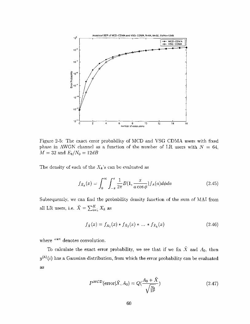
1 0
2 4 6 8number of voice users
10 12 14 16
Figure 2-5: The exact error probability of MCD and VSG CDMA users with fixedphase in AWGN channel as a function of the number of LR users with N = 64,M = 32 and Eb/No = 12dB
The density of each of the Xk's can be evaluated as
fxk(x) i= f B(0 _" 27r
x1, a )fA(a)dqda
a cos 0
Subsequently, we can find the probability density function of the sum of MAI from
all LR users, i.e. X = Ef_, Xk as
f (x) = f, (x) * fx2 (x) * ... * f,(x) (2.46)
where "*" denotes convolution.
To calculate the exact error probability, we see that if we fix X and A0 , then
y(h) (i) has a Gaussian distribution, from which the error probability can be evaluated
as
pMCD(errorl, Ao) =A 0 ±X
2P
(2.47)
60
Analytical BER of MCD-CDMA and VSG-CDMA, N=64, M=32, Eb/No=12dB
-- MOD-ODMA-e- VSG-CDMA
-A10-
10-
10
wO
10 0
10-1
(2.45)

Bit Error Rate of MCD and VSG Users in AWGN Channel (N = 128, M = 32)100
-*- MCD High Rate User--e-- VSG High Rate Uaer-+- MCD Low Rate User
10 - - VSG Low Rate User
102
10-3
10--
10
0 10 20 30 40 50 60 70number of in-cell users
Figure 2-6: BER of MCD and VSG CDMA users in AWGN channel as a function ofthe number of LR users with N = 128, M = 32 and Eb/No = 12dB
The exact error rate can then be found as
pMC A 0 ±XPe CD=E [Q(
2P (2.48)
= f QF )fj,,(x)fA(a)dadx,0 No
2P
The numerical value of the error probability can be evaluated using analytical software
or approximated by averaging P MCD from a large number of independent trials over
the distribution of k's and A's.
Using similar method, we now evaluate the error probability of VSG HR user in
flat fading channel. The matched-filter output for the ith symbol of the VSG HR
61

user in this case can be described as
y(h)(i) V7p( 1 Aob (h)(i)
VIM--
M=V (~~ Aob(h)(i) += (MAobM
ACos kVk +k=1
K
E Vk +k=1
P
ni
Conditioned on all A's and O's, Vk, the MAI term from the kth LR user, has the
following probability distribution
(2.50)PVkAkOk (v) = B( 'As, )MviAk COSqOk
The density of each Vk's can then be evaluated as
fek (H = -- B( 1, x )fA(a)ddaS _ 2 -r M acos
(2.51)
Subsequently, we can find the probability density function of the sum of MAI from
all LR users, i.e. X = EK Xk as
fk(v) = fV (v) * fI2(v) * ... * f(v). (2.52)
To calculate the exact error probability, we see that conditioned on f and A0 ,
y(h) (i) has a Gaussian distribution, from which the error probability can be evaluated
as
PVSG (error Ao) = Q( A + x/7-7
2P
(2.53)
62
i
(2.49)

The exact error rate can then be found as
PVSG =EA,[Q( AO + V
Q2 (2.54)
Q( + ff (v)fA(a)dadv.
2P
The numerical values of the error probability expression can then be evaluated using
analytical software (such as Mathematica) or approximated by averaging PeVSG over
a large number of independent trials over the distribution of A's and V's.
The error probability of the VSG and MCD user in frequency-non-selective Rayleigh
fading channel (obtained by averaging the error probability over a large number of tri-
als with independent fading and MAI statistics) is plotted in figure 2-7 for N = 128,
M = 32, and b = 12dB. We observe that the error rate of the two systems are
practically the same, even when the number of users is very small. The BER gap
that is evident in analysis for the AWGN channel is closed here because averaging
over the fading statistics widens and smoothes the distribution of the MAI seen by
the VSG user. In this case, we predict that the HR user in both systems would have
identical error performance. Simulation results also show the same behavior.
2.5 Results in multipath fading channel
We now compare the error performance of MCD and VSG HR users in a frequency-
selective (multipath) Rayleigh fading channel. We assume the absence of LR users
to emphasize the effect of multipath interference caused by the HR user's own signal.
This assumption is justified since the interference caused by LR users from multiple
paths are essentially MAI, the effect of which has been addressed in the previous
sections.
Under our assumptions, the received signal from a Q-path channel with only the
63

Bit Error Rate of MCD and VSG Users in Flat Fading Channel (N = 128, M = 32)
F MCD High Rate UserVSG High Rate User
-- MCD Low Rate Uaer-- VSG Low Rate Uaer
10
0 10 20 30 40 50 60 70 80 90 100number of in-cell users
Figure 2-7: BER of MCD and VSG CDMA users in Frequency non-selective Rayleighfading channel
HR user can be expressed as
Qr(t) = AqejsSo (t - Tq) + n(t) (2.55)
q=1
where Aq, <qp, -r are the amplitude, phase, and delay of the received signal from the
qth path, respectively. Using matched-filter detection followed by coherent RAKE
combining, the soft decision for the ith symbol in the mth code channel of the MCD
user can be expressed as
QyqYM(D - (2.56)
q=1
where wq ; 0 is the weighting factor for the qth signal path during the combining
process; For example, wq = Aq for maximal ratio combining (MRC), and wq 1
for equal gain combining (EGC)) [55]; ym,q(i) is the output from the matched filter
64
10 0

receiver at the RAKE finger corresponding to the qth signal path such that
MCD ()Ym,qZiTb -T,r
(i-1)Tb -Tq,r
r (t)C (t - Tq,r)dt
M
Ar V/'ej Y(b () )g r)=A /Ijejq b (i) +r=1,roq 1=1
±b(i Z 1)P$,I) (T-r,q)U(Tr,q) + b P)(i 1) iJ (Tq,r) U (Tq,r)) + nm,q
where nm,q is the background Gaussian noise term with zero-mean and variance IO;
u(t) is the step function, Tq,r = Tr - Tq, which gives Tq,r = -Tr,q; the p's are correlation
terms such that
p (Tq,r) = f Tb
iTb-Tr,q
(i-1)Tb
- 'rq,r)u(Tq,r)dt
(2.58)
c(h)(t)c (t + Tr,q)'U(Tr,q)dt
|(&-1)Tb-T,rI(i-=)Tb C h) (t)c(h)(t - Tqr)dt(i-1)Tb
= i b c ()(t)c h)(t + Tr,q)dtiTb-Tr,q
Note that p$(rqO ) - p, (Tr,q). For analytical convenience, we assume that the
receiver can only resolve paths that are separated by integer multiples of chip intervals.
In this case, we have Tq,r = 6 q,rTc, where 6q,r C Z. Since the user signature codes
(p(h) {-1, 1}'s) are random, p(r) (Tq,r), p$2(Tr,q), and P ('rq,r) are zero-mean
'symmetric binomial" random variables with the following variances:
var(py(rq))
var1 p(Tr,q))
N - 16q,r I
N 2
-var(p(-7) (Tq,,r)) =1q~rI
where 6q,r = 6 r - 6q.
Similarly, for the VSG user, the soft decision for the ith symbol after RAKE
65
(2.57)
p ?1) (T,r)
M,1 (Tr,q )
(2.59)
(2.60)
(2.61)
(2.62)
'. MQ C1

combining can be expressed as
L
yVSG(i) = Re{ we OyVSG
1W
(2.63)
where Yq(i), the matched-filter output for the finger corresponding to the qth signal
path, can be expressed as
yiTb+TqVSG
i-T-
AqL ejeq b( (i) +
r (t) c(h)(t - rq)dt
Q
ArLe)r (b(h) (i) 5(O) (7qr)r=1,r5q
+ b(h)(Z + 1)/(1)(Tq,r)u(Tr,q) + b(h) (i _ 1) (-1)(Tq,r)U (Tqr))+ Tq
where nq is the background Gaussian noise with zero-mean and variance 2, and
I 'Tb
(i- 1)Tb+Tqr
iTb-Tr,q+
(i--1)Tb
I iTbiTb
c (h)(t)C(h)(t - Tqr)U(Tq,r)dt
c (h)(t)C(h)(t + Tr,q) U(Tr,q)dt
(2.65)
(2.66)
(2.67)c(h) (t)C(h) (t + Tr,q) dt.
Since the user spreading codes are random, the p's are zero-mean symmetric binomial
random variables with the following variances:
N IrjM r
N2
= var(('1 (Tq,r)) = '2
(2.68)
(2.69)
To evaluate the error performance, we first consider a simple 2-path channel, i.e.
1 E {1, 2}. We assume that T1 = = 0 and that T2 = 62 Tc, where 62 E [1, ]L.
66
(2.64)
0()( ,r ) =
(-1)(Tr
(1) (Tq,r)
(i-)Tb±Tq,,
c (h)(t)c(h)(t - Tq,r)dt
, q
var(p(O) (Tq ) )
var ( (-1) (-r,r))

We first analyze the MCD user, for which the RAKE finger outputs in this case are
simplified to
y M CD j)Ai\/bm(i)
M
+ E A2 V/Pej2 (b(h) (0 2)j=1 (2.70)
+ b(i - (1p;)(72)) + nm,l
yMCD -A 2 V/Pej02 bm(i) + %/PAl (b(h) (i) p) (T 2 )
j=1 (2.71)
+bh(i + l)p 1 ) (-7 2 )) + n7, 2 .
The soft decision after RAKE combining is then
2
yMCD -j#9qMC DYMCDj -Re{Z wqe My'1Di)
q=1
=(w1AI + w2A 2)xiPbm(zi) + (w1A1 + w2 A 2 ) V cos #2 b (i) Pm(T 2)
+ cos 2VP( (2.72)1=1,l m
M
+ A1 w2b (h) (j) p 1 (0-) 2 2b h) (ij=1
± )WlP(-I) (T 2 )
+ Aiw 2 b,(h(i -- 1)pQ(-T 2 ))) + win,1 + w2nn,2 cos 02
where, since the data symbols are transmitted as 1 or -1 with equal probability,
b (h) (i) p$)p(( 2 ), b(h)(Z)p(0) (-7 2 ), b h)(i - 1)p (J(1 2), and b h)(i + 1)p( 1)(-T 2) are inde-
pendent, zero-mean symmetric binomial random variables with the following vari-
ances:
var (b ( pT2)
var(b (h(i - 1)p 30 (72))
N -2, var(b ()Pi (-T 2 )) = N -62
62 A (b (h)(i + 1)p(I)(-T 2 )) =2
N27 1 'I N2
Also, note from eq. 2.72 that the term bn M()pm(T 2 ) appears in both RAKE fingers.
67
(A2w~b () )p(0 (,r2)
This is the correlated multipath interference (CMPI) component, as it introduces
correlation between the output of RAKE fingers 1 and 2. All other p's contribute to
the uncorrelated MPI (UCMPI) [9].
Subsequently, the SIR of the MCD user conditioned on Aq, 9q, and Tq can be
expressed as
SIRMCD _ (wiA1 + w2A 2 )2 (2.73)IMCD + 2 o(w + wCOS2 q$2 )
where IMCD = 'CMPIj + IU/CM{PI is the overall multipath interference power normal-
ized by the transmit power, where IC d C P are the normalized power of
correlated and uncorrelated MPI, respectively, which can be expressed as
ICD (w1A 2 +w 2A 1 ) 2 Cos 2 2 N -6 (2.74)_L CMPIN2
IMCy =( A 2W2 + A 2w2) cos 02 M6 + (M -1)(N - 6) (2.75)(AMI 1 1 N2
Note that the weight on CMPI, i.e. (w1 A2 + w2 A 1 )2 is larger than that on each of
the UCMPI, i.e. (A w + A2W2). However, also note that for large M, the total MPI
suffered by the MCD user is always dominated by the UCMPI.
We now analyze the received SIR for the VSG HR user in the same two-path
channel. The output from each of the RAKE fingers of the VSG HR user can be
expressed as
y1 A, -wb(i) VMPA 2ej(2 (bi) (O) ( 2) (2.76)
+ b(i - 1); -5)(T2)) + h1
ySG =A 2 -- e 2b(i) ±A MP(b(i)7(0 )(72)+ M (2.77)
+ b(i + 1) ((-2)) + i!2
68

The soft decision after coherent RAKE combining is then
2yVSG(Z) =Re{Z wqe-OyVSG
q=1
=(wiA + w 2 A 2 ) b(i)(2.78)
+ (Aiw 2 + A 2 wI) cos 02 PMI 0 ) (T2 )
± A 2w 1 P M cos 02 pf1 (T2 ) + A 1w 2 cos $2 PMfi(1 ) (--72)
+ w15 1 + w 2 2 cos 02
With random spreading codes and BPSK modulated symbols, b(i)5( 0) (T), b(i-1)i(~1 )(T),
and b(i+1)/i() (-T) are mutually independent, zero-mean symmetric binomial random
variables with the following variances:
-N 62Var( 0()(T)) = N 2 (2.79)
N2Var(/I 1 )(r)) = N2 (2.80)
Var(p)(-r)) N2 (2.81)
We also observe from eq. 2.76 that the term VfPM3( 0 ) (T2 ) appears in both RAKE
fingers and is hence the CMPI.
The SIR of the VSG user can subsequently be found as
SIRVSG _ (wiAI + w 2 A 2 )2 82)JVSG + + w2 cos 2)(
where IVSG I+ U PI is the total multipath interference power suffered
by the VSG HR user normalized by its transmit power; IcjiTh and IUMPI are the
normalized correlated and uncorrelated MPI power, respectively, and can be expressed
69

as
ICVSPG = M 2 (A1 w2 + A 2 w1) 2 cos2 2 2 (2.83)
IgGPI = M 2 cos 2 q2 (A w + A 2W) (2.84)
Note that if 62 is much smaller than -, the correlated MPI will have a much larger
power than the uncorrelated MPI for large M.
We now compare the SIR of the MCD and VSG HR user in the two-path channel.
Since contributions from symbol energy and background noise in both cases are the
same as shown in eq. (2.73) and (2.82), the comparison of SIR can be reduced
to finding the differences in the power of multipath interferences (MPI). The MPI
experienced by the MCD HR user can be expressed as:
IMCD =(wiA 2 +W2A1 2 202N 62
+ (A2W2 + A 2W2) cos 2 0 2 M 6 2 +(M - 1)(N -62)
N2 N=zcos2q$2((w1A 2 +w2A1)2 N 26 2 (2.85)
+ (A w + A w2)((M N2 +62
2N-6 2 21 N= cos 2 ( w1 w2 1A 2 N 2 + (w2 A + w2 A 2)
while the MPI suffered by the VSG user can be rearranged as
N- 62IVSG =M 2 ( Aw 2 + A 2wI) 2 cos 2 M N2
+ M 2 cos 2 N2 (A w2 + A w)
= COS 2 0 2((A2W2 ± A2W2) M(N - 62) - M(M - 1)62 + M 2 62 (2.86)= c2 2 1 N 2
+ 2A 1 A 2w 1 w 2 M(N-M 2 )
M(N - M62 ) (W2A2 + W2A2) M=cos2
2 ( 2ww 2 A1A 2 N 2 + 21 2 1 N)'
70
The difference in their MPI power is then:
Idff =IVSG - iMCD
MN - M 2 62 N - 62=cos2 $ 22wiw 2 A1A 2( N 2 N 2 )
COS 2 22w1W2A 1A 2 (M - 1)N - (M 2 - 1)62 (2.87)
- N 2
(M - 1)(N - (M + 1)62)= cos2 b22w 1w2 A 1 A 2 N 2
The above equation gives several important insights:
1. As long as w1 , w2 , A 1, A 2 are all positive (i.e. as long as we combine the output
of the paths), and M > 1 (i.e. HR transmission), the VSG user suffers from
a larger MPI power than the MCD user if 62 < N (i.e. T2 < +). If
MA-< T 2 < 1, then the MCD user suffers a larger MPI power than the VSG
user.
2. The SIR of MCD and VSG users from just a single RAKE finger should be
exactly the same, as this corresponds to the case of selection combining where
either w, or w2 is zero but not both.
The intuitive explanation for the statements made above is that when time offset
between the two paths is small compared to the symbol interval of the VSG user, the
VSG user suffers a great deal of CMPI, while the interferences seen by the MCD user
is always dominated by UCMPI contributed by other parallel code channels. As the
time offset grows, the CMPI suffered by the VSG user quickly decreases, while the
MCD user still has some CMPI component from the code channel where the desired
symbol lies. Note that the threshold at which the SIR of MCD and VSG are equal is
independent of the amplitude and the weighting factor used for each path.
Furthermore, if we let r2 grows beyond M but less than Tb, i.e. by letting - <
62 < T, while the SIR expression for the MCD user are not affected, the VSG user
71

will not have CMPI anymore. In this case, the MPI suffered by the VSG becomes
IVSG -m 2(Aw + A2w2) Cos 2 2 -62(Al2+A 1 2 MN 2
+ M 2 cos2 22 (A 2w + A w)
-(A 2w + A w) cos2 02 M1 2 2 1 N2
In this case, we see that
IVSG - iMCD - -2wjw 2A1 A2 Cos 2 N -62 < 0N2 <02
(2.88)
(2.89)
where the difference is contributed by the CMPI suffered by the MCD user. In this
case, VSG user will always have a higher SIR than the MCD user.
If we let T2 grow even further such that it is larger than T (which makes 62 > N)
then neither VSG or MCD user will suffer from any CMPI. In this case, the MPI
suffered by both users can be expressed as
IVSG _ IMCD = (A 2W2 + A w) Cos 2 M1 2 21 02N2
(2.90)
which means that MCD and VSG users have identical SIR.
We now extend the analysis to a general Q-path channel, where Q > 2. We rank
the path i.d. according to the delay offsets, i.e. T1 > T 2 > ... > TQ and assume that
T - ri < T , i.e. the delay spread of the channel is less than the symbol interval of a
VSG HR user. In this case, the soft decision of the MCD user after RAKE combining
can be expressed as
Q Q-1 Q
yMCD V (Z wqAqbm (i) + Cos qqr(UCMPI(Tq,r)
q=1 q=1 r=q+1
Q
+ UUCMPI(rq,r)) + Wq COS q)q=1
(2.91)
where UCMPI (Tq,r) and UUCMPI(Tq,r) are the normalized correlated and uncorrelated
72

MPI components, respectively, between paths q and r, which can be expressed as
UCMPI (Tq,r) = (wqAr + wrAq)bm(i)p$. 2m(Tq,r) (2.92)
UUCMPI (Tq,r) zWqAr( (b,(i)p) (FTq,r) + bi (i - 1 P (Tq,r)1=1,1#m
(2.93)+bm(i - 1)p(y)(Tq,r)) + wr Aq(
1=1,I0m
+ bl(i + 1)rho('1 (Tr,q)) + bm(i + 1)PQm(Tr,q))
Due to the random spreading and BPSK modulated transmitted symbols, we observe
that
1. E[UCMPI(Tq,r)] = E[UUCMPI(Tq,r)1 = 0,
1 and2. UCMPI(Tq,r) and UUCMPI(Tq,r) are uncorrelated for all 1
q+1 < r < Q.
3. Both UCMPI (Tq,r) and UUCMPI(Tq,r) are i.i.d. for all pairs of q and r, where
1 < q < Q - I and q+1 < r < Q.
With these observations, we first see that the variance of the MPI components, found
in the same way as that in the two-path case, can be expressed as
var (UcMpI (Tq,r)) =E[UCMPj (Tq,r)I
2N - 16q (2.94)
=(wqAr + WrAq )2 N 2
var(UucMpI(Tq,r)) =E[U2CMpI (Tq,rI(2.95)
w2 - N -| 6q |(W2 A2 2 A2)((M - 1) N 2 ' + M N )
and that given A's and O's, the overall power of multipath interferences can be ex-
73
(bt (Op~o (Tr,q)
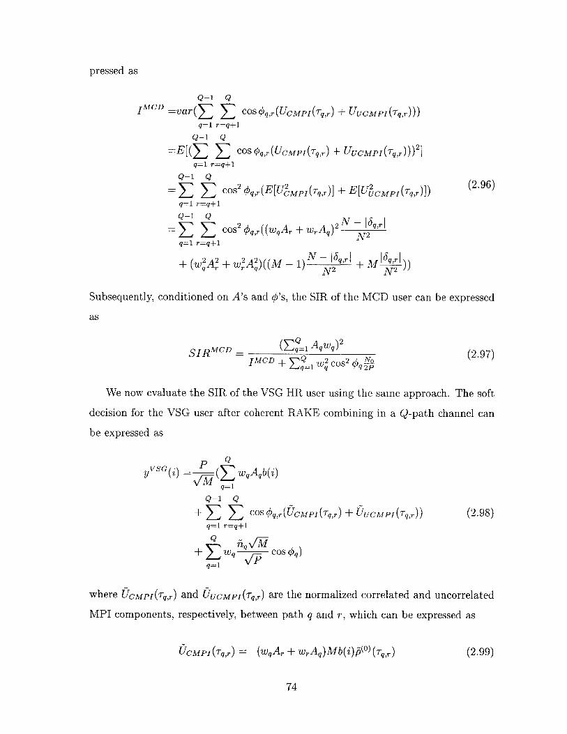
pressed as
Q-1 Q1 MCD =var(Z S COS Oq,r(UCMPI(Tq,r) + UUCMPI(Tq,r)))
q=1 r=q+1
Q-1 Q=E[(E > COS4q,r(UCMPI(Tq,r) + UUCMPI(Tq,r)))2]
q=1 r=q+1
Q-1 Q
=- S cos2 q,,r(E[UMpI(T,r)]+ E[U2CMpI (Tq,r)]) (2.96)q=1 r=q+1
Q-1 Q 2 N- |q6r|
Q-1 Q Cos2 #q,r ((wqAr + wrAq) N 2
q=1 r=q+1
+ (w2A2 + W2 A )((M - 1) N - |6T,r + '2
Subsequently, conditioned on A's and #'s, the SIR of the MCD user can be expressed
as
SIRMCD - MC (9 )2
IMCD + E W 2 qOS2 (9
We now evaluate the SIR of the VSG HR user using the same approach. The soft
decision for the VSG user after coherent RAKE combining in a Q-path channel can
be expressed as
yVSG(j) PY V1\"M q qq=1
Q-1 Q
+ 5 E cOS Oq,r (UCMPI(Tq,r) + UUCMPI(Tq,r)) (2.98)q=1 r=q+1
+ q+( 7Wq-q / COS #9)
q=1 VIP
where CMpI(Tq,r) and (UcMpI(Tq,r) are the normalized correlated and uncorrelated
MPI components, respectively, between path q and r, which can be expressed as
UCMPI(Tq,r) (wqAr + WrAq)Mb(i)(0 )(T,r) (2.99)
74

UCMPI(Tqr) qAr Mb(i - 1)) (Tq,rU U C M I ( T q r) - q r( 2 .1 0 0 )
+ wrAqv AIb(i + 1) P)(Tr,q)) (
where the U's possess the same statistical properties that are specified for the U's
earlier (such as pairwise independence, i.i.d., etc.). The variance of each of the MPI
components, found in the same way as that in the two-path case, can be expressed as
var (UcMpI (Tq,r)) =E[UMPI (Tq,r)]
(wqAr + wrAq)2IM(N - 6 qrl) (2.101)
N 2
var( UCMPI(Tq,r)) =E[U CMpI(Tq,r)]
2 2 6 qr (2.102)WqA +WrAq)M N 2
Conditioned on A's and O's, the overall power of multipath interference can be ex-
pressed as
Q-1 Q
1 VSG =var ( E cos qq,r (CMPI(Tq,r) + UUCMPI(Tq,r)))
q=1 r=q+1
Q-1 Q
E S cos 2 4,r(E[UMp I (Tq,r)] + E[U2CMPI(Tq,r)])q=1 r=q+1 (2.103)Q-1 Q)M( 6r)
cos 2 Oq,r ((wqAr + wrAq )2M( N 2 6qr|1
q=1 r=q+1
+ (w A2 +W A )M 16,r|
Subsequently, the SIR of the VSG user can be expressed as
SIRVSG - VS (Q 1 Aqwq) 2 2
(2.104)IV SG +X: 2 Cos o
+ s 1 tCD an Gp
As before, the difference between the SIR of MCD and VSG user depends on the
75

difference of their MPI power, which can be found as
diff =IVSG - iMCD
Q-1 Q
Z S cos 2 Oq,r(wqAr + wrAq) 2 M(N- 1qr1)q=1 r=q+1
+A A) N2 (wN - |6WA) I+ A +r N2 (wqAr+WrAq N 2 (2.105)
N - 6qr | |6 |I- (w A2 + w A )((M -1) N2 N M 2
Q-1 Q
I:E Cos 2 Sr 2 wqArWr Aq (M - 1)(N - (M + 1) 6qr 1)
q=1 r=q+1
In this case, we see that if time offsets between all possible pairs of paths are small,
i.e. if 6,r < Nor equivalentlyTqr < T1 for 1 < q < Q - 1 and q + 1 < r < Q
(such as indoor or densely populated urban area), the VSG user will suffer from a
larger MPI power than the MCD user. On the opposite, if T < ,r < :I- for all
possible q's and r's (such as in less populated urban and suburban areas), the SIR of
the MCD user is going to be worse than that of the VSG user.
Similar as the two-path case, if we let all rq,,'s grow beyond - but less than T,
i.e. by letting ! < Tq,r < T for all 1 q < Q - 1 and q +1 r < Q, while the
SIR expression for the MCD user is not affected, the VSG user will not have CMPI
anymore. In this case, the MPI suffered by the VSG becomes
Q-1 QVSG Cos 2 qq,r(Aqwr +A 2 2 (2.106)
q=1 r=q+1
In this case, we see that
JVSG _ =MCD -WrWqArAq COS2 qr N - 6 qr < 0 (2.107)-MD 55 2 rE~ ~ o 2~~ N 2
q=1 r=q+1
where the difference is contributed by the CMPI suffered by the MCD user. In this
case, VSG user will always have a higher SIR than the MCD user.
If we let Tq,r's exceed T, then neither VSG or MCD user will suffer from any
76
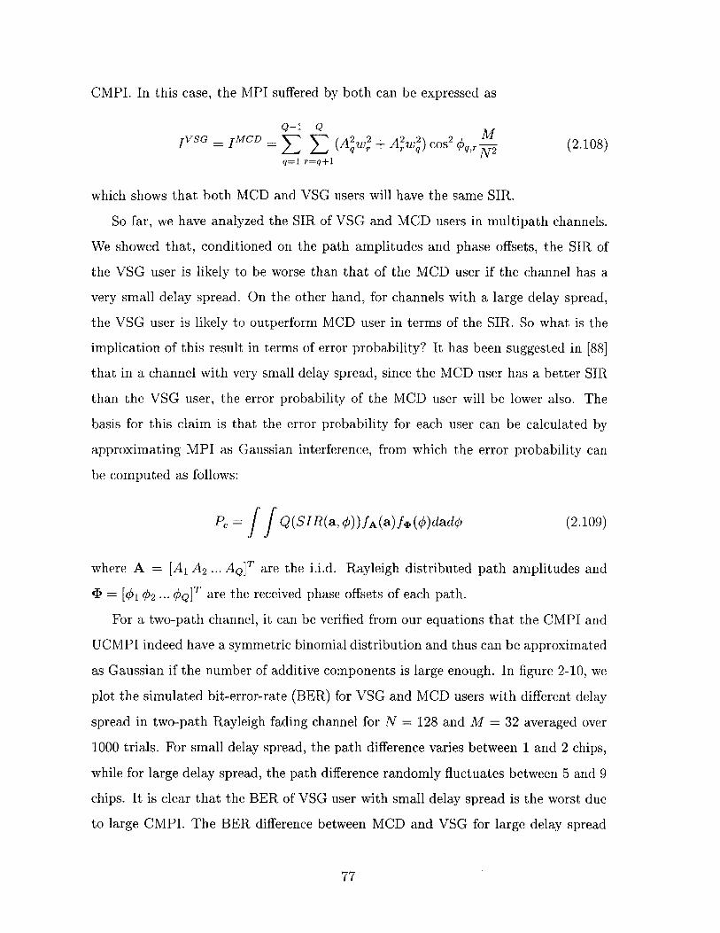
CMPI. In this case, the MPI suffered by both can be expressed as
Q--1 Q
IVSG = 1 MCD = Q (1+ AQw) CosW2q2WM)(S2.
q=1 r=q+1
which shows that both MCD and VSG users will have the same SIR.
So far, we have analyzed the SIR of VSG and MCD users in multipath channels.
We showed that, conditioned on the path amplitudes and phase offsets, the SIR of
the VSG user is likely to be worse than that of the MCD user if the channel has a
very small delay spread. On the other hand, for channels with a large delay spread,
the VSG user is likely to outperform MCD user in terms of the SIR. So what is the
implication of this result in terms of error probability? It has been suggested in [88]
that in a channel with very small delay spread, since the MCD user has a better SIR
than the VSG user, the error probability of the MCD user will be lower also. The
basis for this claim is that the error probability for each user can be calculated by
approximating MPI as Gaussian interference, from which the error probability can
be computed as follows:
Pe = JJ Q(SIR(a, #))fA(a)fq (#)dado (2.109)
where A = [A 1 A2 ... AQIT are the i.i.d. Rayleigh distributed path amplitudes and
< = [102 ... OQ]T are the received phase offsets of each path.
For a two-path channel, it can be verified from our equations that the CMPI and
UCMPI indeed have a symmetric binomial distribution and thus can be approximated
as Gaussian if the number of additive components is large enough. In figure 2-10, we
plot the simulated bit-error-rate (BER) for VSG and MCD users with different delay
spread in two-path Rayleigh fading channel for N = 128 and M = 32 averaged over
1000 trials. For small delay spread, the path difference varies between 1 and 2 chips,
while for large delay spread, the path difference randomly fluctuates between 5 and 9
chips. It is clear that the BER of VSG user with small delay spread is the worst due
to large CMPI. The BER difference between MCD and VSG for large delay spread
77

may be a bit subtle, since MCD is always dominated by UCMPI, but with careful
observation, we do see that the BER of the VSG user slightly outperforms that of
the MCD user in this case.
Interestingly, when the number of paths grows beyond two, we do not have a con-
clusive answer as to which scheme outperforms the other, even though we know how
SIRs of the two systems compare. The key observation we have is that in this case the
use of Gaussian approximation may lead to serious errors in BER calculation because
the MPIs are not only non-Gaussian but may also have an asymmetric distribution.
In this case, a user with a larger correlated multipath interference power (and thus
smaller SIR) may actually have a better BER.
To see an example, let us consider the case where N = 64, M = 16, Q = 3, and
the delays being T1 = 0, T2 = Tc, and T3 = 3Tc. The received signal of the VSG HR
user from different paths is shown in figure 2-8.
-3 R-2 '- 1 PO P1 P2 P3 P4 P5 P6 P7 P8
Path 1 bl b2 b3 ..... bl6
Path 2R-3 -2 R 1 0 p1 2 P3 P4 P5 P6 p7 p8
bl b2 b3 ..... bl6
-3 -2 I p 0 p 1 p2 P3 P4 P5 6 7 P8
Path 3 ...... bl b2 b3 ----- b16
Figure 2-8: VSG Signals in a Multipath Channel
Without loss of generality, let's look at the demodulation of bit 2 assuming equal
78

gain combining and fixed path amplitudes. The VSG user sees the following MPI:
4I G 64 (2b2 (P1P2 + P2P3 + P3P4 + P1P4 + PlP3 + P2P4 )
+ bi(pop1 + P1P-2 +P2P-1 + P3PO + P1P-1 + P2Po)
+ b3 (p4p5 +P2P5 +P3P6 +P4P7 +P3P5 +P4P6))
=I1 (12 + I + 13)16
where pi's are i.i.d. symmetric Bernoulli random variables with probability of 0.5
being 1 and probability of 0.5 of being -1; 1i is the corresponding normalized MPI
from the ith bit, for which we see that
I1 = bi(pop, + P1P-2 + P2P-1 + P3PO + PiP-1 +P2P) (2.111)
12 = 2b2 (pIp2 +P2P3 +P3P4 +P1P4 +P1P3 +P2P4) (2.112)
13 b3 (p4p5 + P2P5 + P3P6 + P4P7 + P3P5 + p4p6) (2.113)
It is clear that I2 causes CMPI while I, and 13 causes UCMPI. To compute the
error probability, it can be easily verified that the distribution of UCMPI, i.e. I + 13,
are symmetric binomial and can therefore be approximated as Gaussian since the
number of terms in the sum is sufficiently large. The CMPI, i.e. I2, on the other
hand, has the following distribution shown in figure 2-9, which is clearly neither
Gaussian nor symmetric. Since the I's are correlated with each other, the variance
of the MPI can be calculated as
a (I G) - P 36P(2 1 4var (IVSG 2 (var(I1) + var(I2) + var(13)) = 26 (2.114)
256 256
and the SIR of the VSG user can be found as
SIRVSG 144 (2.115)
MP 36 + 24Nt o(21
With a given received power, the error probability of the VSG user can be calculated
79

1/2
3/8
1/8
-4 0 12 2
Figure 2-9: An example of the probability mass function for the correlated MPI ofVSG user in a three-path channel with short delay spread
as
VSG 3 8 1 24 1 12 (2.116)PeMP = Q( )_ +__( +__) (.16
8 12 + 12 + 24N 2 12 + 24NP P P
where we assume the UCMPI, i.e. I1 and 13 as Gaussian interferences since the sum
of the two is a sufficiently large binomial random variable that can be approximated
as Gaussian. It can be verified that Pe VfG is significantly smaller than Q(/SIR jS)for SNR (i.e. -= ) exceeds OdB.No No
Let us now consider demodulation of the bit from the second code channel of the
MCD user in this case. Since most of the multipath interferences for the MCD users
come from other code channels, the total SIR can be approximated as
SIRCD 144SI24+ 24N (2.117)
P
by ignoring the correlated MPI for code channel 2. This SIR is clearly greater than
SIRvSG . The corresponding error probability for a given received power can then be
80

approximated as
Pe MCD QSRmD(218
which is slightly optimistic than the realistic error probability due to the ignorance of
the correlated MPI. However, the reader can verify that Pem D will be greater than
Pell' for T exceeds 3dB.
In figure 2-11, we plot the BER performance of MCD and VSG HR user in a
three-path Rayleigh fading channel under different types of delay-spread for N = 128
and M = 32. We see that for small delay spread (T1, 2 = T, and T 2,3 = 2Tc), the
VSG user outperforms the MCD user even though it sees a larger MPI power. On
the other hand, if the delay spread is large (T 1,2 = 6T, and T2 ,3 = 8Tc), the MCD
user outperforms the VSG user. The BER behavior in three-path channel is there-
fore completely opposite of that in the two-path channel because of the asymmetric
distribution of MPI.
At this point, the reader may question how would addition of LR users into the
system impact the result. We can answer this question by approximating the effect
of LR users as additional background noise. From figures 2-10 and 2-11, we see
that as the amount of background noise increases and gradually dominates over the
MPI, the differences between the BER of MCD and VSG HR user diminishes. We
therefore expect the same thing to happen if the number of LR users in the system
increases. In such cases, the choice of using MCD or VSG will depend more on
tradeoffs between physical layer and higher layer implementation costs since both
systems exhibit practically the same error performance.
81
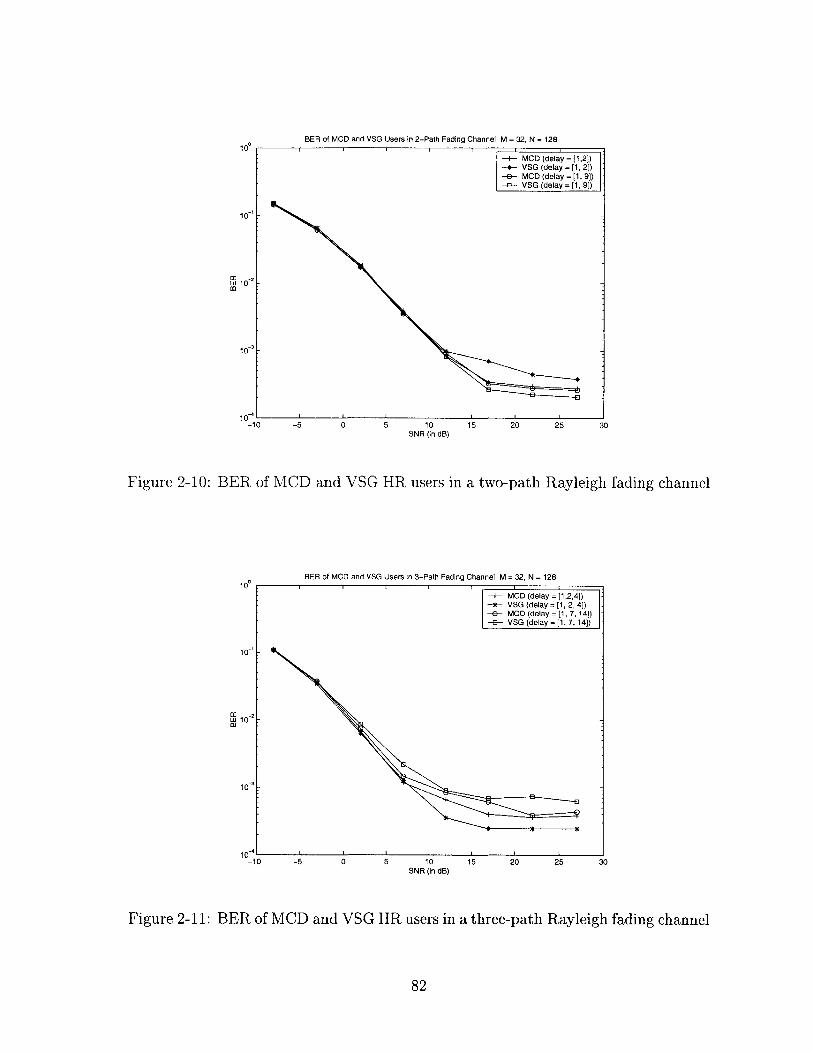
BER of MCD and VSG Users in 2-Path Fading Channel: M = 32, N = 128
-+- MCD (delay = [1,2])-*- VSG (delay =[1, 2})-&- MCD (delay =[1, 9])-B-- VSG (delay =[1, 9])
............. .... -
-5 0 5 10SNR (in dB)
15 20 25 30
Figure 2-10: BER of MCD and VSG HR users in a two-path Rayleigh fading channel
BER of MCD and VSG Users in 3-Path Fading Channel: M = 32, N = 12810,
10'
1C -2w 10
10-
10-I-10
+ MCD (delay = [1,2,4])-*-- VSG (delay = [1, 2, 4])-e- MCD (delay= [1, 7,14])-s- VSG (delay =[1, 7, 14])
-5 0 5 10SNR (in dB)
15 20 25 30
Figure 2-11: BER of MCD and VSG HR users in a three-path Rayleigh fading channel
82
10
10
w 10
10-10
10 3

2.6 Chapter Summary
In this chapter, we compared the error performance of MCD- and VSG-CDMA HR
users in AWGN, flat-fading and multipath fading channels. Instead of employing
traditional Gaussian approximation that assumes all interferences to be Gaussian
random variables, we evaluate the bit-error rate using the true interference distribu-
tions. We made three key observations. First, in an ideal AWGN channel, we found
that the VSG user outperforms MCD user at moderately high Eb/No if the number
of LR interferers in the cell is small. As the population of LR user increases, both
users achieve the same error rate. In flat-fading channel, however, both MCD and
VSG user seem to have identical bit-error rate, since averaging over fading smoothes
the distribution of interferences seen by both users and make them become similar.
Second, in multipath fading channels, we found that the VSG user is likely to suffer
from a larger interference power than the MCD user if the channel has a small delay
spread. The opposite is true for channels with moderately large delay spread. Third,
we found that for channels with three or more paths, the SIR does not truly repre-
sent the error probability because multipath interferences may have an asymmetric
distribution. Therefore, the decision on whether to use VSG or MCD for such chan-
nels should be decided on a case-by-case basis rather than rely on theoretical SIR
comparison as has been done in the past[48].
83

Chapter 3
Multistage Interference
Cancellation based on MMSE
Optimization
In this chapter, we present two effective decision-feedback multistage interference
cancellation algorithms that can be used at the DS-CDMA base-station receiver to
suppress the user-to-user (multiple-access) interferences (MAI). Both detection algo-
rithms are derived by minimizing the mean-squared error (MSE) of the cancellation
output at each stage, and both schemes use a weighting matrix to incorporate the re-
liability of MAI reconstruction in every stage into the cancellation process. Our first
algorithm uses a MMSE optimized feedback matrix to reconstruct and cancel the MAI
and has similar computational complexity as that of a conventional multistage paral-
lel interference canceller (PIC). We show that this scheme exhibits significantly better
spectral- and energy-efficiency than the conventional PIC. Our second algorithm is
more complex than the first one such that it uses a feedforward matrix together with
feedback cancellation to suppress MAI. We deduce the jointly optimal (MMSE) feed-
forward and feedback processing matrices at each stage. We illustrate that, with
complexity on the same order as that for linear joint detection, the performance of
this receiver not only significantly surpasses that of the linear joint detectors but also
approaches the single-user performance bound.
84

3.1 Background and motivation
The idea of suppressing multiple-access interferences (MAI) in a DS-CDMA system
using multistage interference cancellation (IC) was first proposed in [70]. This type of
receiver, shown in figure 3-1, operates in a stage-by-stage manner. The initial stage is
a matched-filter bank followed by minimum-distance decision devices (i.e. quantizers).
In every subsequent stage, the receiver first reconstructs the MAI suffered by each
user based on symbol estimates of all in-cell users made at the previous stage and
then subtracts these MAI estimates from the users' matched-filter outputs. The
results from the cancellation process are sent to quantization devices to determine
the symbol estimates for the current stage. This multistage IC is also referred to as
the conventional parallel IC (PIC) [46], as it performs MAI cancellation for all users
(simultaneously) in parallel.
(i)Y Z,
bK'
Y 2 Z2 F /(()2 Zb2
r(t)
yK Z -
-MAI
MAI 2
MAIK
o bK
Figure 3-1: A general multi-stage decision-feedback interference canceller
The PIC is attractive for practical implementation because it has a lower complex-
ity than many other joint detectors [46]. A key weakness with the conventional PIC,
85

however, is that it assumes the symbol estimates made at every stage to be entirely
accurate [71, 86]. Hence, complete MAI cancellation based on tentative decisions
from the previous stage is always performed. Since the quality of symbol estimates
at early stages, particularly the initial stage, can be quite poor due to excessive MAI,
the performance of this receiver often suffers from severe error propagation [62]. Con-
sider, for example, in a binary phase-shift-keying (BPSK) modulated system, if a
wrong symbol estimate is used to reconstruct the MAI, the power of the correspond-
ing MAI component will be quadrupled after cancellation. Subsequently, the error
rate of a PIC often diverges, in which case the probability of symbol error at later
stages becomes higher than that at earlier stages [75].
To alleviate the effect of error propagation, [62] proposed the use of partial MAI
cancellation. The essential idea is that since the symbol estimates tend to be inac-
curate at early stages, only a fraction of MAI based on those estimates should be
canceled. As symbol decisions become more reliable in later stages, more substantial
MAI cancellation becomes appropriate. To implement this idea, the receiver assigns
a small weight to MAI cancellation (to cancel a fraction of MAI) at early stages and
a larger cancellation weight at later stages. The performance of this receiver has
been shown to significantly outperform the conventional PIC in a system employing
perfect power control [62]. Two aspects of this receiver can still be improved, how-
ever. First, the cancellation weights are generated in a trial-and-error fashion from
computer simulations rather than via a systematic method. It is therefore unclear
which set of cancellation weights leads to the optimal performance under a specific
design criterion. Second, the receiver assumes uniform error performance among all
subscribers and thereby assigns the same weight to cancel the MAI from all users' at
a given stage. In reality, however, even with random spreading codes and reasonable
power control, the quality of symbol estimates may still differ significantly from one
user to another [75]. It is therefore preferable to assign disparate cancellation weights
to the MAI caused by different users to further improve the system performance.
An alternative approach to PIC is the well-known successive interference canceller
(SIC), which can actually be viewed as a weighted multistage IC that detects one user
86

per stage [78, 51]. In a typical SIC, users are ranked according to their received signal
power. The strongest user is detected first based on its matched-filter output. The
MAI from this user is then reconstructed based on its symbol estimate and subtracted
from matched-filter output of all other users. The receiver then proceeds to deter-
mined the received symbol of the second strongest user, after which it reconstructs
and cancels the MAI caused by this user from the matched-filter output of the re-
maining users. This procedure continues until all users in the system are detected.
For a system with K users, SIC can be viewed as a K-stage weighted IC that, at stage
k, it assigns a cancellation weight of 1 to the MAI from the first k - I users (with
the largest received signal power) and a weight of 0 to the MAI from all other users.
Only the kth user is detected at the kth stage. It has been shown that the use of
SIC can asymptotically eliminate the effect of MAI and approach the single-user per-
formance bound, provided that the received powers of the users differ in exponential
order [51]. In practice, however, it is almost impossible to make the users' received
powers to be exponentially distributed, and thus SIC almost never approach such
good performance. In fact, in today's DS-CDMA system where good power control is
employed, the received powers of all users are approximately the same. In this case,
the performance of the SIC, both in terms of bit-error rate (BER) and latency, is
often inferior to that of conventional PIC [46].
An alternative solution to weighted or partial interference cancellation is to en-
hance the quality of symbol estimates at the first stage using linear joint detectors
(such as the decorrelator or the linear MMSE detector) instead of the matched filter
[75]. Such approaches indeed lead to performance that surpasses the conventional
PIC but at the expense of higher complexity. Furthermore, it is known that the
error performance of this type of receivers at later stages may be worse than that
of the decorrelator or the linear MMSE detector alone [75]. This happens because
these receivers make use of the noisy matched-filter output at subsequent stages. To
further improve the receiver performance, a feedforward linear processing unit has
been introduced to work together with feedback cancellation at every stage. Such
proposals lead to several decision feedback joint detectors with feedforward process-
87

ing [8, 13, 31, 75]. Most of these receivers, however, still assume that the symbol
estimates from the previous stage is completely accurate and hence may suffer from
severe error propagation when the assumption fails.
Here, we present two types of weighted multistage ICs derived using constrained
MMSE optimization at every stage, and the key difference between our algorithms
and most of the prior techniques is the use of a weighting matrix that assesses the
quality of symbol estimates in the previous stage. The weighting matrix mainly de-
pends on the error probability of the symbol estimates in the previous stage, which
can be easily approximated by estimating the SIR of the cancellation output or by
using interleaved pilot sequences. These two ICs differentiate from each other in com-
plexity constraints. The first algorithm uses a MMSE-optimized feedback matrix to
reconstruct and suppress MAI and has a complexity comparable to that of the partial
and conventional PIC. We show that this detector clearly outperforms both the con-
ventional and partial PIC in terms of spectral- and energy-efficiency. However, due to
its complexity constraint, this scheme may not perform as well as the linear joint de-
tectors do, and its error performance is far from the single-user bound for a crowded
system. Our second technique applies jointly (MMSE) optimized feedforward and
feedback matrices to suppress MAI and therefore has a higher complexity than our
first method. It exhibits superior error-rate performance, which not only significantly
surpasses that of the linear joint detectors but also approaches the single-user perfor-
mance bound in a few iterations. Yet, the complexity of this receiver is comparable
to that of linear joint detectors.
The outline of this chapter is as follows. Section 2 introduces the basic sys-
tem model for multistage interference cancellation. Our first algorithm that employs
MMSE-optimized feedback MAI cancellation is presented in section 3, and its perfor-
mance is shown in section 4. Our second algorithm that uses feedforward and feedback
matrices to suppress MAI is presented in section 5, and its performance is illustrated
in section 6. Section 7 summarizes the chapter. Derivations of the weighting matrix
is shown in appendix A.
88

3.2 Existing multistage decision-feedback interfer-
ence canceller
3.2.1 System model
We consider a DS-CDMA system with K equal-rate users communicating simultane-
ously over a common frequency-nonselective channel, each using a unique spreading
code. The composite baseband signal arriving at the receiver can be expressed as
K
r(t) =( Aksk(t - Tk)ejckk + n(t) (3.1)k=1
where Ak, #k and Tk are the received amplitude, phase and delay of the kth user's
signal, respectively; n(t) is the additive white Gaussian noise (AWGN) with one-sided
spectral density No = 2a2 ; Sk(t) is the kth user's transmitted signal such that
00
Sk(t) E bk(i)ck(t - iTb)00 N (3.2)
00 N
S bk(i)Eck(iN+j)(t-iT-ITc)i=-00 j=1
where bk(i) is the ith data symbol of user k; ck(j) E {-1, 1} is the jth chip of user
k's spreading code; T and T, are the symbol and chip durations, respectively, where
Tb = NTc, with N being the spreading gain; 0(t) is the time-limited chip modulating
waveform such that IT d(t)Idt
For analytical convenience, we assume that the receiver has perfect timing, phase,
and amplitude estimation for all users, which makes coherent detection possible.
Without loss of generality, we also assume that each user transmits a frame of L
symbols, where L > 1, and that the maximum difference in reception delay between
different users is less than one symbol interval, i.e. Tmax - Tmin < T, where Tmax =
maxl<k K{Tk} and Tmin - mrnl<k KTk}. In this case, the matched-filter output for
89

the lth symbol transmitted by user k, denoted as yk(l), can be described as follows:
I (l+1)Tb+-TkYk lTb+k
r(t)ck(t - Tk)e-sk
K
Ak(l)bk(l) + 3 ei(--k)(Am(l)bm(l)pO (l)m=1,mAk
± Am(l - 1)bm(l - 1)p7 -(l) U(rm - Tk)
+ Am(l + 1)bm(l + 1)Pk m(l)U(T - Tm) + ?2k(l)
(3.3)
where nk (1), the background noise term, is a zero-mean Gaussian random variable
with variance a2 ; Ak(1) is the amplitude of user k's received signal in its lth symbol
interval; u(t) is a unit-step function such that u(t) = 1 if t > 0 and equals to 0
otherwise. The summation term contains MAI from all other users (on user k) due
to cross-correlation of the spreading (signature) sequences. The correlation terms in
the MAI for k 0 m are defined as
) - -1:f f( b-T k+Tm Ck(t - Tk)cm(t - Tm)dt( ) = 1 k - T t
41b ) _ r Ck(t - - k)Cm(t - T,)dt
if Tm > Tk.
if Tk > Tm.
(3.4)
- f(-1)Tb+Tk+Tm
p ~(l ) = JlTb+rklTb+Tk -- Tm
ck (t - Tk)cm(t - Tm)dt
(t - k)cm (t - Tm)dt.
Note that p(7I (l) = p )(l - 1). The corresponding symbol decision bk(l) can be
made based on Yk(l) using the minimum-distance rule [19].
We now develop a vector notation for detection in the case where each user trans-
mits a frame of L symbols, i.e. 1 = 1, 2, ... L. We let y = [y(l) y(2) ... y(L)]T, where
y(l) = [y1(l) y2 (1) ... YK ( -)]. It is straightforward to verify that the vector y can be
90
(3.5)
(3.6)
=
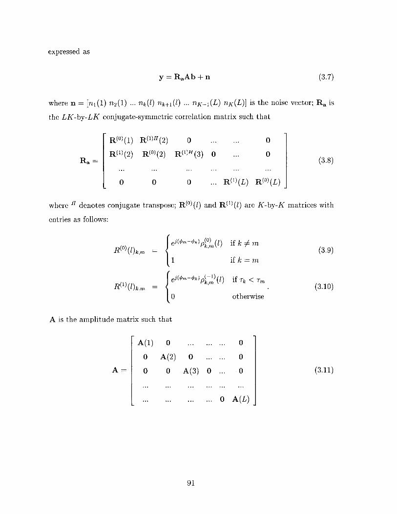
expressed as
y = RaAb+fn (3.7)
where n = [n1(1) n 2 (1) ... nk(l) nk+1(l) ... nK-1(L) nK(L)] is the noise vector; Ra is
the LK-by-LK conjugate-symmetric correlation matrix such that
Ra =
R(0)(1) R(l)H(2) 0
R(1)(2) R(0)(2) R()H (3)
0 0
0
0
0
0(3.8)
where H denotes conjugate transpose; R(0 )(1) and R(1 )(1) are K-by-K matrices with
entries as follows:
RCo)(l)k,m
R01 ) (l)k,m
if k# m
if k m
if Tk <Tm
otherwise=0
10
(3.9)
(3.10)
A is the amplitude matrix such that
A(1) 0
0 A(2)
0
0
0 0 A (3)
0
0 0 (3.11)
... ... ... ... O A(L)
91
... R(M (L) R(O) (L)
eit*n-Ok) (0)
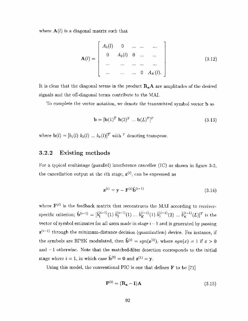
where A(1) is a diagonal matrix such that
A1 (l) 0 ... ... ...
A(1) 0 A2 (l) 0 ... ... (3.12)
L ** ... ... 0 AK(l).
It is clear that the diagonal terms in the product RaA are amplitudes of the desired
signals and the off-diagonal terms contribute to the MAI.
To complete the vector notation, we denote the transmitted symbol vector b as
b = [b(1)T b(2)T ... b(L)T]T (3.13)
where b(l) = [b,(l) b2 (l) ... bk(l)]T with T denoting transpose.
3.2.2 Existing methods
For a typical multistage (parallel) interference canceller (IC) as shown in figure 3-2,
the cancellation output at the ith stage, z('), can be expressed as
z(2) = y - F(z)b(-l) (3.14)
where FW is the feedback matrix that reconstructs the MAI according to receiver-
specific criterion; 0-' = [b(ii 1)(1) b4i1) (1) ... b-1 (1) b0)( 2 ) ... 07 (L)]T is the
vector of symbol estimates for all users made in stage i -1 and is generated by passing
z(-') through the minimum-distance decision (quantization) device. For instance, if
the symbols are BPSK modulated, then b() - sgn(z(')), where sgn(x) = 1 if x > 0
and -1 otherwise. Note that the matched-filter detection corresponds to the initial
stage where i = 1, in which case (o) = 0 and z(1) = y.
Using this model, the conventional PIC is one that defines F to be [71]
F() = (Ra-I)A (3.15)
92

Matched (i+^ )r(t) -0 Filter -
Bank-
Fb
Figure 3-2: Multi-stage decision-feedback interference canceller in vector form
for all stages. Intuitively, this means that at every stage, the receiver attempts to
cancel all off-diagonal terms in RaA (i.e. complete MAI cancellation). This model
was derived assuming that the previous symbol estimates used for MAI reconstruction
exactly resembles the original data symbols. In realistic systems, however, the quality
of these symbol estimates can be quite poor, particularly at early stages [62, 81]. The
error propagation caused by the wrong estimates significantly degrades the error
performances of the conventional PIC such that under many circumstances its error
rate does not decrease beyond two stages [75].
To improve the performance of conventional PIC, partial PIC is proposed, which
defines the feedback matrix as: [62], [81]
F() - p(W (Ra - I)A (3.16)
where p(i) E [0, 1] is a weighting constant depending on the stage number i. At early
stages (i.e. small i), p(i) is small since the tentative symbol decisions are likely to be
unreliable. The value of p(') increases with i as symbol decisions become more reliable
in later stages. While this method offers significant performance improvement over
the conventional PIC for a system with perfect power control, two aspects of this
mechanism can be further improved. First, the receiver assigns all users the same
93

cancellation constant and is thus not favorable for systems where the users' error
performance clearly deviates from one another. Second, the cancellation weights at
each stage were chosen arbitrarily in a trial-and-error fashion. A simple, systematic
and robust method needs to be developed to calculate the cancellation weights. Next,
we introduce a class of weighted multistage ICs that overcomes these two problems
and offers a much improved performance over both conventional PIC and partial PIC.
3.3 MMSE-based multistage decision-feedback in-
terference cancellation
3.3.1 Derivation
In this section, we propose a MMSE-based weighted parallel interference canceller
(WPIC) that dynamically adjusts the feedback matrix F2 to minimize the mean-
squared error (MSE) between the actual transmitted symbols and the symbol esti-
mates in each stage. In specific terms, we would like to find F() that satisfies
F(- = F()* = argminFJ{E[(z() - Ab)H(Z(i) - Ab)]} (3.17)
For the derivation process, we make three assumptions that are typically used in
analyzing the uplink of a DS-CDMA system. First, we assume that data symbols
of different users are independent and that the successive symbols from the same
user are also independent. Thus, in terms of correlations, we have E[bk(l)b,(j)] =
6[k - m]6[1 - J] for all 1, j, k, and m, where 6[n] is the unit-sample (discrete impulse)
function. Second, we assume that E[bk(l)bm(]j)] < E[b,(l)bk'(l)] = 1 for all 1 = j
and/or m = k. This implies that the detected symbol estimates retain the statistical
properties of the transmitted symbols. Third, we assume that spreading codes and
received amplitudes of all users are known and deterministic rather than random, as
in a realistic system with reasonable power control.
Under the given assumptions, we proceed to find F()*. Since minimizing the
94

mean-squared error denoted in eq. 3.17 is equivalent to minimizing the trace of the
covariance matrix of z(') - Ab, i.e.
F(') = argminF(1 )tr(cOv(Z(i) - Ab))} (3.18)
where tr(.) denotes the trace operation. We start the derivation process by simplifying
the covariance matrix as follows:
cov(z(') - Ab) = cov((Ra - I)Ab + n - FEU-')
E[((Ra - I)Ab + n - F(- 1))((Ra - I)Ab + n - Fbi-)H
= (Ra - I)AE[bbH]AH(Ra - i)H + U2 Ra + F(i)E[(-i1 )(i- 1)H]F(i)H
-(Ra - I)AE[bb(i- 1 )H]F()H - F(')E[('-l)bH]AH(Ra - J)H
(Ra - I)AAH(Ra - I)H + F(i)F(i)H - (Ra - I)AE[bb(i- 1 )H]F(i)H
-F()E[(~Z1)bH]AH(Ra - i)H + U2 Ra
where simplification in the last step comes from assumptions that E[bbH] I,
E[nbH] = E[nbH] = 0, and E[b0-1 )(i 1)H] = I. Let E[bb(i-1 )H] - A_(i1), we
can rewrite the covariance matrix as
cov(z(2) - Ab) = (Ra - I)AAH(Ra - I)H + F(i)F(i)H - (Ra - I)AAa(Z) F(i)H
-F()Aa(i- 1 )HAH(Ra - i)H + U2 Ra
- ((Ra - I)AAa('~0 - F(Z)((Ra - I)AAa(Z1) - F())H
+Oc 2Ra + (Ra - I)A(I - Aa(Z 1 )Aa(i- 1 )H)AH(Ra - I)
Since ((Ra - I)AAa(' 1 ' - F(Z))((Ra - I)AAa(2~) - F(i))H is positive semi-definite,
we see that the choice of F() that minimizes the trace of the covariance matrix (and
thus the mean-squared error) at the ith stage is
F(')* - (Ra - I)AAaG 1l (3.19)
95

where Ai - E[bf(i-1 )H].
Clearly, the choice of Aa() determines F()*. If we let Aa(') = I for all i, then we
obtain the conventional PIC. Similarly, if we assign Aa() = p()I, we have partial PIC.
The Aa(') of our choice, which is derived in appendix A for a M-ary phase-shift-keying
modulated (M-PSK) system, is a LK-by-LK matrix such that
Aa(W =
A (',0 (1)
A(, -1(2)
A('),' (1)
A ('),0 (2)
0
A('),0 (2)
0
0
0
0
0
A(),)'(L) A(z),O(L)
(3.20)
where
1 - (1 - cos ?g)Pe
= ,0 -4- Lm ej2727(Q(sin (y~ - Om,k(l)) 7m,k ())(e~ - 1)A (')O)m,k =+Q(sin ( - + Om,k (l)) 7m,k(l))(ej - 1))
0
ifk=m
if k h m and i = 1
if k $ m and i > 1
A(u(,1()mk U(Tm - rk)u(2 - i) M jE ej m (Q(sin ( - 0m,k(l)) 'm,k(l))(e M - 1)m=O
+Q(sin (7 + km,k(l)) m,k(l))(e'r - 1))
A(),- (l)m,k = u(rk - rm)u(2 - i)Z ej 2 (Q(sin( - km,k (l) Ym,k ())(e 9 - 1)m=0
+ Q(sin (7 + m,k(l)) 'jrm,k(l))(e& - 1))
where Pe(' is the symbol error probability of user k in the ith stage, u(t) is unit-step
96

function, and
_ m An1)po (1) sin (2~ + Om -_ ,
Om,k(l) = tan-' Am() ) Am 0 kAk(l) + Am(l)p (l) COS (2nl- +M m 'k)
Ak(l)2 + Am l)2 ( 2)4(1)) + 2Ak(l)Am(l)PA(l) COS (p27 + (k - qk)
Mm,k MAIk(l) - A2 ()(p 0 )(())2 + 0.2
Am(l)p ~Q(l ± 1) sin (2mr + #m - 7k)Om,k(l) = tan- 'P mM
Ak(l +1) + Am(l)p- 1(l + 1) COS (2mr
Ak(l + 1)2 + Am(l)2(2 + 2Ak(l + 1)A p ( +1) cos((p + __ +
Ym~~l)MAIk(l + 1) - A2 (1)(p -l)(Y + 1)) 2 + U2
Am 1) sin(2 + (m - )6m, k~l tan-'()kmM+0
k
Amn( -1) + Am Y 1) cos (F + m - k)
Ak(l - 1)2 + Am (l)2(pi) (1 - 1))A p (1 - 1) COS + m - $7 )Ymk MAIk(l - 1) - A2 (1)(p( - 2 ± 0.2
where
K
MAIk(l) = ( ((Am l)p((l))2 Am 1)p (l))2 mm=1,mAk
+(Am(l + 1)p~l (l))2U(Tk _ Tm)).
is the total MAI power suffered by user k during its lth symbol interval.
Intuitively, Aa(2) measures the correlation between the symbol estimates at stage
i and the actual transmitted symbols. The mth diagonal term (Aa(m, M)), where
M = K(l - 1) + k, denotes the correlation between the the estimate for the lth symbol
or user k in stage i with its original transmitted symbol. Therefore, the diagonal terms
measures the reliability of symbol estimates in stage i. Each off-diagonal term, on the
other hand, denotes the correlation between a transmitted symbol and the detector
output for another different symbol. These correlation terms arise from the effect of
MAI.
97

3.3.2 Asymptotic approximation
The necessity to compute every entry in Aa leads to significant amount of compu-
tations in addition to conventional PIC (particularly at the first stage), despite the
fact that complexities of these receivers are all on the same order. We now show
that by examining the asymptotic behavior of Aa(i), we can significantly reduce the
complexity of our proposed receiver for a large system with reasonable power control.
As the number of users become large, i.e. K -+ oc, Aa can be approximated as
a diagonal matrix (as shown in appendix A) such that
W( 0 0 ... ... 0
0 W WO 0 0 ... ... 0 ( .1oai (3.21)
0 ... ... ... 0 0 W(W
where W( is a K-by-K diagonal matrix that can be evaluated depending on mod-
ulation format used in the system. For a M-PSK modulated system, we found (in
appendix A) that
W3 ~1 - Pe (1 - cos ). (3.22)
Intuitively, the reason why Aa(i can be approximated as a diagonal matrix for
large K is because as number of users in the system increases, the effect of MAI from
any particular user becomes negligible when compared to the MAI from all users, and
therefore the correlation between transmitted and received symbols of different users
approaches zero. Hence, under asymptotic approximation, the cancellation weights
in the ith stage solely depend on W( 's, which measures the reliability of each user's
symbol estimates at the ith stage. The larger W( is, the more reliable user k's
estimate is, and a larger weight will subsequently be applied to cancel the MAI from
this user.
The proposed receiver implemented using asymptotic approximation is shown in
98

figure 3-3. The soft decision output for the lth symbol of the kth user in stage i can
now be expressed as
Km=1,mok
+ Am(l -(1 - 1)p- 1)(l)U(7m - Tk)(3.23)
+ Am(l + 1)b(- (± + 1)p (l)u(Tk - Tm)) + flk(l)
Here, instead of computing all entries of the LK-by-LK matrix F, we only need to
compute one cancellation weight for each user and hence achieve significant complex-
ity reduction.
(i)Zi0)
(i)
Y2 + Z2(1)
M ()
MAIAl
MAI (t1)
MAI K(L)
C0
03
b 1i{)
wK
/((i-1)
b (1)
b
w2(I
Figure 3-3: Weighted multistage interference canceller
3.3.3 Simplified MMSE-based weighted PIC
So far, the complexity of our proposed receiver can be reduced for a large system such
that it just needs to compute one cancellation weight for each individual user at each
99
r(t)
7:
kZ i(1) =yk ei- *--k) )Wi- 1) (Am(l )b(-I)(l)p~ (0 )

stage. To further reduce its complexity so that it is equivalent to that of conventional
or partial PIC, we constrain the weighting matrix AM to be:
A(') = w)I (3.24)
where w() is a cancellation constant applied to all (M-PSK modulated) users in stage
i and I is the identity matrix. In this case, the cancellation output becomes
z) = RaAb - w()(Ra- I)Ab + n (3.25)
We would again like to find the optimal choice of w(') such that it minimizes the
mean-squared error at stage i under the constraint, i.e.
w(iopt = min{(i){E[(z() - Ab)H(z(i) - Ab)]j (3.26)
To proceed, we first assume that
E[bk(l)bm(j)HI = E[bk(l)bm(j)H]0
E[bk(l)bm(j) (i= 11- Pe)(1 - cos0
if k - m and I - j
otherwise.
if k = m and I =j,
otherwise.
100
(3.27)
(3.28)

Now we simplify the mean-squared error as follows:
MSE(2) = E[(z(z) - Ab)H(z() - Ab)]
= E[((Ra - I)A(b - w(')b) + n)H (Ra - I)A(b - w(2)b) + n)]
= E[((Ra - I)A(b - w(Z)b))H((Ra - I)A(b - w(')b)) + E[nHn]
E[bHAH(Ra - I)H(Ra - I)Ab + WHAH (Ra - I)H (Ra - I)Abw
-bHAH(Ra - I)H(Ra - i)Abw - WbHAH(Ra- I )H(Ra - I)Ab]
+E[nHn]L K
S J5(MAIk(l) + (w(2))2MAIk(1)1=1 i=1
-2wMAIk(l)(1 - Pe 1)(1 - cos ))) + LKU2
where MAIk(l) is defined in eq. (3.21). To find the w(0 that minimizes MSEW, we
simply take the derivative of MSE() with respect to 0 and obtain
d{ MSEW)I L K 27d{w(} = 2 (w() MAIk(l) - MAIk(l)(1 - Pedj1 )(1 - cos -))) (3.29)
The choice of w(0 that satisfies the MMSE criterion under this constraint is thus
( zI ZkI1(1 - p(i1) cos ))MAIk (l)W ()Ot-= k- L_ (3.30)
11 j:K IMAl (1)
In the case of perfect power control and random spreading codes, the amount of
MAI experienced by all users in every symbol period is approximately the same. The
weighting factor can then be simplified as
K(i),opt - Pe-(1 - cos ))MAIk
Kk=1MAIk (3.31)K -Pe((1 - COS
K
101

Intuitively, w(') depends on the average error probability of all users at stage i weighted
by the MAI suffered by each user at the output of its matched filter. This receiver,
which we name as the simplified weighted PIC (SWPIC), is considerably simpler than
the our previous solutions because only it only computes one cancellation weight for
each stage.
3.3.4 Practical considerations
To implement the proposed receiver in a practical system, we carry out the following
procedures in stage i:
1. Estimate the symbol error rate for each user in the previous stage.
2. Compute the weighting matrix Aa(Z1 ) according to eq. 3.20. (For a large
system, just compute the corresponding weight for each user (i.e. W i 1)(l)k,k)
according to eq. 3.22; For SWPIC, just compute W according to eq. 3.30.)
3. Find Ra and A using the knowledge of user signature waveform and received
amplitude, phase, and delay offsets.
4. Subtract RaAAa(2 )b(Z) from the matched-filter output vector y.
5. For each user, pass its corresponding cancellation output through the quantiza-
tion device to obtain the updated symbol estimates for the current stage.
6. Repeat procedures 1 through 5 for subsequent stages until the target BER has
been reached for all users in the system or as desired.
In practical applications, since the proposed receiver operates on a frame of data
symbols each time, the data frame size, i.e. L, needs to be carefully chosen based on
the tradeoff consideration between bit-error rate and latency requirement. The larger
the frame is, the longer the latency, but the better the performance since interferences
at the edge of the frame will be negligible when compared to the frame size.
A remaining question is how to estimate the error probability for each user at
a given stage. There are two solutions. First, the error probability of each user
102

can be approximated by first estimating the signal-to-interference ratios (SIR) of the
cancellation outputs (i.e. elements in z(')) and then applying Gaussian approxima-
tion. For a M-PSK modulated system, the error probability can be approximated
as Pe ~ Q(v/SIR sin ') [55]. Second, each user can employ interleaved pilot (train-
ing) sequences within each data frame. The error probability can then be estimated
by observing the error rate of these pilot sequences. Even though the use of these
training sequences result in some loss of throughput, we will see in section 3.4 that
such loss is negligible comparing to the overall capacity improvement achieved by the
proposed receivers over the conventional PIC.
3.4 Performance analysis of MMSE-based weighted
multistage decision-feedback IC
3.4.1 Asymptotic error-rate analysis
In this section we analyze the error performance of the proposed receivers (using
MMSE feedback cancellation and Aa) for a M-PSK modulated DS-CDMA system
with K users. Since computation of the exact error probability is burdensome for
multistage IC (as illustrated in [71]) and does not yield significant insight, we evaluate
the error probability for a large system using classical Gaussian approximation [40].
We assume K -* oo, N -+ oc and i = 3, and that the user spreading (signature)
codes are random, which is a good model for a practical DS-CDMA system that uses
pseudo-random (PN) signature sequences with period much longer than the spreading
factor. We also assume a symbol-synchronous system, i.e. Tk = 0 for all k E [1, K],
which corresponds to the case of strongest MAI [78]. In this case, the correlation terms
in the MAI can be simplified such that p() = 1 = 0 for all m, k E {1, 2, ... K,
and pfM pmk.
An important measure of the system performance is the signal-to-interference ratio
103
(SIR). In our case, the SIR at the matched-filter output for user k can be found as
A 2SIR MF Ak
k Z=1,jk AE[p ]E[bb] + (.A~j k2 j 3 (3.32)
where E[bjb '] = 1 for M-PSK modulation with equi-probable selection of constel-
lation points and E[p ,] = 1 due to random spreading. Furthermore, in the case
of perfect power control, i.e. A 1 = A 2 = ... = AK = A, the SIR of matched-filter
detection for all users can be simplified to:
SIRMF - 1 1 (3.33)IR K-1 + No +NN 2A 2 2
for a large system.
We proceed to compute the SIR for the conventional PIC. The SIR for the can-
cellation output of user k at stage i is
SIRPIC,(i) Ak j=,jAk AE[Pk]E[(bj - bj - )(bj - b j H + 3.0.
A 2(3.34)
Y= 2,jAk -(1 cos ) +
where the relationship E[(bi - b -)) (bj - b -)H -)(1 - COS m) for a large
system has been derived in appendix A. Again, this SIR can be simplified in the case
of perfect power control as
SIRPIc,(i) 1(335)2#Pe(-1)(1 - cos N) +M)+2A 2
where Pe(z-) is the average symbol error rate of all users in stage i - 1.
Similarly, for our proposed detector, i.e. the weighted PIC (WPIC) with MMSE
feedback cancellation, the SIR for the kth user at stage i after weighted MAI cancel-
104

lation can be found as
SIRWPIC,(i)
where W) =3,3
A E[p? ,kE[(bj - W4)b( -O)(b -1)Nb H
A 2~k
A (1 - (Wj, )2) +
j=1, A Pe>(1 - cos -)(2 - (1 - cos + 9
1 + (cos2 - 1)Pe ~0. Simplification at the second step comes from
the approximation that E[(b, - W<]b )(b- W J l)H] 1 - Too see
this is a valid approximation, we have
E[|bI - V ~i)|(i-)12] =E[(bj - W ) (bj.
=1 -- 2W)$ E [b 1)] + (W))2
~1 - 2W) - (W 3|)2
=1 - (W ])2
where the approximation in the last step assumes E[bib jl)] = 1 W and E[b> 1) b -')I =
1, which has been validated in the last section and appendix A. We see that in
this case, the interference power from the jth user is suppressed by a factor of
2 In the case of perfect power control, we can deduce the SIR of
all users to be
SIRWPICi -1
Pe(i- 1)(1 - cos -)(2 - (1 - cos I)Pe(i-1)) +
The error probability for all three receivers can be calculated using classical Gaus-
sian approximation [17] as
Pe() = Q(sin S- SIR(i)).M
(3.38)
We are interested in analyzing the convergence behavior of our proposed algorithm
105
- W 1) ) H3,3 3
(3.36)
(3.37)

under Gaussian approximation in AWGN channel. Note that since SIRWPIC,(i) is a
function of PeWPIC,(i-1) through the weighting matrix A-(1), PeWPIC,(i) is then also
a function of PeWPIC,(i-1), i.e.
PeWPIC,(i) = H(PeWPIC,(i-1)) (3.39)
To find the error probability at which the receiver reaches convergence, we just need
to find when PeWPIC,(i) = PeWPIC,(i-1)
Figures 3-4 (a)-(f) show the convergence behavior of WPIC as a function of the
number of stages for small, large, and over-loaded systems with BPSK modulation
and signal-to-noise ratio (SNR = Eb/No) of 7dB. The convergence curve for PIC is also
plotted for comparison. We see that, in figures 3-4(a) and 3-4(b), which corresponds
to a system with load =_ 0.5 and 0.75, respectively, the error floor for WPIC and PIC
are essentially the same, except that it takes WPIC fewer stages to reach convergence.
In system with larger load, i.e. 3 = 1 and # = 1.25, which corresponds to figures
3-4(c) and 3-4(d), respectively, we see that the error floors of WPIC becomes better
than PIC, while WPIC also takes much fewer iterations to reach convergence. For
overloaded system, i.e. figures 3-4(e) and 3-4(f), which corresponds to / = 1.5 and
2, respectively, we see that both receivers perform poorly, with WPIC being slightly
better.
3.4.2 Simulation verification
The performance of (MMSE-based) WPIC is verified via simulation for an asyn-
chronous BPSK modulated and uncoded (i.e. no channel coding) system employ-
ing random spreading codes with a spreading gain of N = 128. The signal-to-
(background)noise ratio (SNR) for each user is 7 dB, which resembles perfect power
control. The IC operates on every frame of 800 data symbols, which includes 12
training symbols. For a system with more than 64 users, asymptotic approximation
is applied for WPIC. The performance of the WPIC and SWPIC in AWGN chan-
nels in one stage, two stages, and five stages are shown in figures 3-5(a), 3-5(b),
106

and 3-5(c), respectively, where we plot the average BER vs. the number of active
users. The corresponding performances in a flat-fading channel are plotted in figures
3-6(a), 3-6(b), and 3-6(c), with the average SNR per user being around 20 dB. The
amplitude of each user in this case fades independently from symbol to symbol and is
modeled as a Rayleigh random variable. Error performance of the matched filter and
conventional PIC are also plotted in each figure for comparison. From these figures,
we see that the loss of 1.25 percent in throughput due to the use of training sequence
is negligible compared to the amount of capacity gain achieved by WPIC and SWPIC
over conventional PIC. For instance, for a two-stage IC in an AWGN channel, if we
impose a BER target of 10', the use of WPIC can accommodate about 65 users,
while the conventional PIC can only accommodate about 45 users. This corresponds
to 45 percent increase in the capacity.
Tradeoff between BER and Eb/No for the different receivers after 1, 2, and 5 stages
are shown in figures 3-7(a), 3-7(b) and 3-7(c), respectively, for a half loaded system
(64 users with a spreading gain of 128). We see that in all stages, the WPIC not only
exhibits a better tradeoff than the other algorithms but also yields a much lower error
floor and can converge more quickly than the others to reach the target error rate.
The SWPIC also exhibits a better tradeoff than the conventional PIC. Its behavior is
significantly worse than WPIC in later stages, however, due to the lack of disparate
weighting factor for each user, even though the simulations are done for the case of
perfect power control and random spreading codes.
107
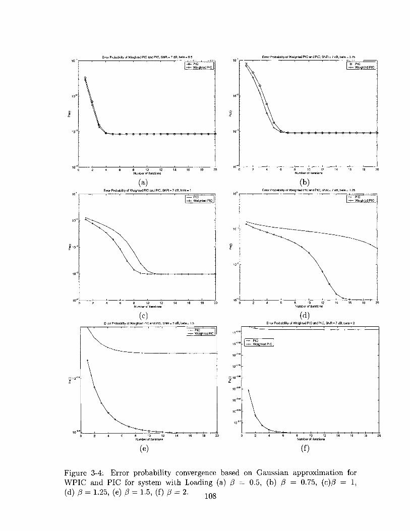
to-,
10-
10'
to-,
10-
10,
0 2 4 6 8 10 12 14 16 18 21Number of iterations
(a)Error Probability of Weighted PIC and PIC, SNR = 7 dB, beta = I
2 4 6 8 10 12Number of iterations
14 16 18 20
Error Probability of Weighted PIC and PlC, SNR = 7 dB, beta = 0.75
) 2 4 6 a 10 12 14 16 15 20Number of iterations
(b)Error Probability of Weighted PIC and PIC, SNR 7 dB, beta 1.25
--- PIC+- WeightedPC
6 8 10 12Number of iterations
14 16 18 20
(c)Error Probability of Weighted PIC and PIC, SNR = 7 dB, beta = 1.5
--- PICWeighted PIC
2 4 6 8 tO 12 14 16-1
-10E. I
10~9 S0 2 4 6 8 10 12 14 16 18
Number of iterations
(e)
10
10 _.
10-0
tow
Sto-
a-
10 -6
100
10-ON
10 0
(d)Error Probability of Weighted PIC and PIC, SNR = 7 dB, beta = 2
20 0 2 4 6 8 10 12 14 16 18Number of iterations
(f)
20
Figure 3-4: Error probability convergence based on Gaussian approximation forWPIC and PIC for system with Loading (a) # 0.5, (b) # = 0.75, (c)# = 1,(d) #3 = 1.25, (e) # = 1.5, (f) 3 = 2. 108
Error Probability 01 Weighted PIC and PIC, SNR = 7 dB, beta= 0.5
-PIC+-4 Weighted PICT
to-'
10
to
10*
to-2
-PIC+- Weighlted PIC
to-, V
---PIC+Weighted PIC
-- 'PlC' .
100
to- I0
- [PigtePC
_.M M M - M - M - - - - - - - -
.
I I I I I I I I I 10 - 1
0

Performance of Weighted IC in AWGN Channel, Sp Factor = 128, Eb/No=7 dB, 1 -Stage
10
10to-
10
10
to'
10
10 t
10
- Matched Filter-e- PIC-.- WPIC--- SWPIC
10 20 30 40 50 60 70 80 90 1Number of Active Users
(b)Performance of Weighted IC in AWGN Channel, Sp Factor = 12B, Eb/No=7 dB, 5-Stage
10'
10
0 10 20 30 40 50 60 70 80 90 100Number of Active Users
(c)
Figure 3-5: Error probability of weighted PIC vs. the total number of users in AWGNchannel, (a) 1 stage, (b) 2 stages, (c) 5 stages
109
- Matched Filter-e- PIC
+ WPIC+ SWPIC
0 to 20 30 40 50 60 70 80 90 100Number of Active Users
(a)Performance of Weighted IC in AWGN Channel, Sp Factor = 128, Eb/No= 7 dB, 2-Stage
to-'
1 to
to'
- Matched Filter-P- PIC
+ WPIC-- SWPIC
3I
1
2
3
4
2
3
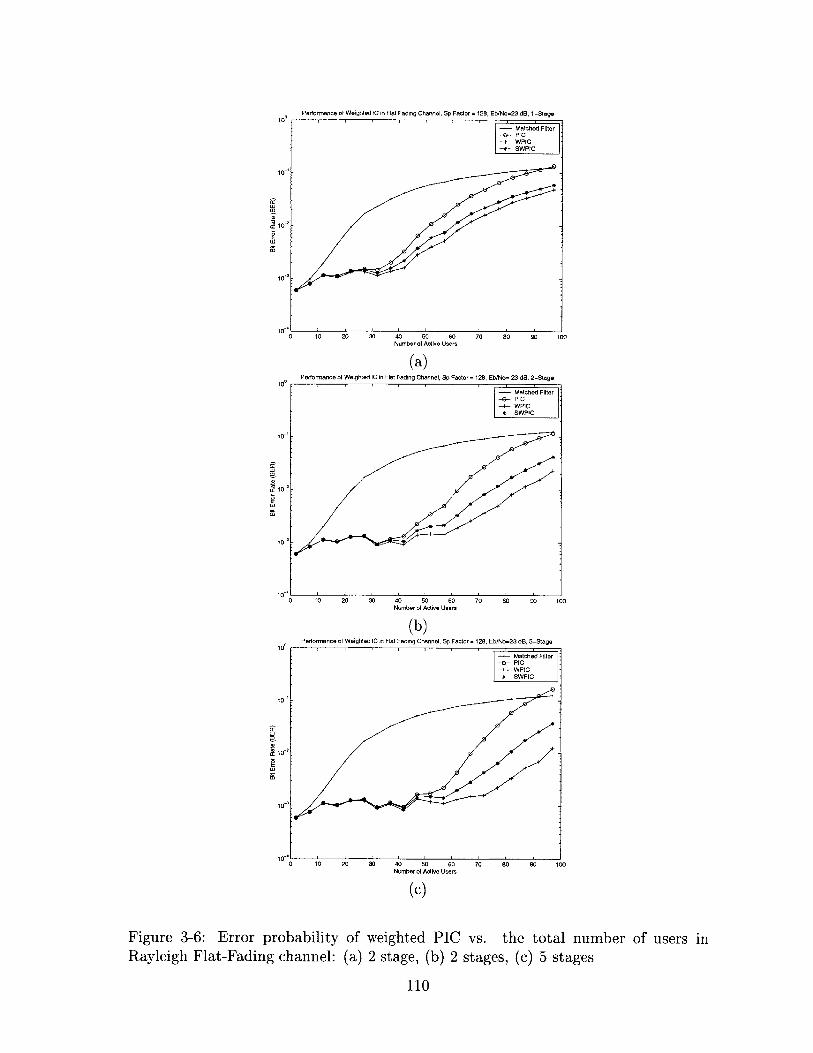
Performance of Weighted IC in Flat Fading Channel, Sp Factor = 128, Eb/No=23 dB, 1 -Stage10
to 20 30 40 50 60
to-'
to-
10'to- 0
10'
70 80 90 1
Performance of Weighted IC in Flat Fading Channel, Sp Factor = 128, Eb/No= 23 dB, 2-Stage
tO 20 30 40 50 6010 20 30 40 50 60
Number of Active Users
(b)
0 10 20 30 40 50 60 70Number of Active Users
70 60 90 11
Mo
0
80 90 100
(c)
Figure 3-6: Error probability of weighted PIC vs. the total number of users inRayleigh Flat-Fading channel: (a) 2 stage, (b) 2 stages, (c) 5 stages
110
- Matched Filter-e- PIC-+- WPIC-*- SWPIC
- Matched Filter-e- PIC-+- WPIC-a- SWPIC
10 20 30 40 50 60Number of Active Users
(a)
to-
10 t
10-2
to'
to'
1o-'
T 10'
10
10,
Performance of Weighted IC in Flat Fading Channel, Sp Factor = 128, Eb/NO=23 dB, 5-Stage
- Matched Filter-e- PIC--- WPIC-a- SWPIC
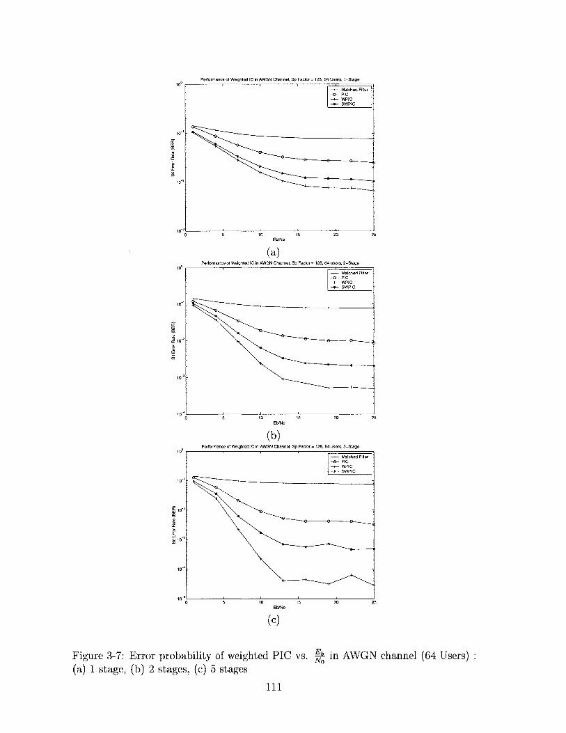
5 10 15 20Eb/No
(a)Performance of Weighted IC in AWGN Channel, Sp Factor= 128, 64 users, 2-Stage
10 15 20 25Eb/No
(b)Performance of Weighted IC in AWGN Channel, Sp Factor = 128, 64 users, 5-Stage
- Matched Fitter- -- PIC-4- WPIC-a-- SWPIC
- 0-6202
10
10-
10-2
10
~ 0
to-s
10-2
to
10
10-
16
ai -
10"
to-s0
Figure 3-7: Error probability of weighted PIC vs. - in AWGN channel (64 Users)No
(a) 1 stage, (b) 2 stages, (c) 5 stages
111
Performance of Weighted IC in AWGN Channel, Sp Factor 128, 64 Users, 1-Stage
- Matched Fitter-9- PIC-4- WPIC
SWPIC
- Matched Filter0 PIC
-I- WPIC-*- SWPIC
10
to-'
10-I 0
5 10 is 20 25Eb/No
(c)
5
-
-

3.5 Multistage IC with both feedforward and decision-
feedback linear processing
So far, we have developed a class of multistage ICs using MMSE optimized feedback
matrix to achieve significant performance improvement over the conventional PIC.
Due to its complexity constraint (to be comparable to the conventional PIC), the
performance of our receiver is still worse than that of linear joint detectors and is
quite far from the single-user performance bound. For the rest of the chapter, we
introduce additional complexities to enhance the detector performance. Specifically,
we show that by adding a feedforward linear processing unit to the multistage IC
and by jointly optimizing the feedforward and the feedback matrix using the MMSE
criterion at every stage, we obtain a receiver whose performance not only surpasses
that of linear joint detectors but also approaches the single-user performance bound
in a few iterations.
3.5.1 Framework of multistage decision-feedback IC with feed-
forward matrix
Using vector notations developed in section 3.2.1, the structure of a multistage IC
with feedforward linear processing module is illustrated in figure 3-8. In the ith stage
Matched + 0)
r(t)- Filter MBank-
Fb
Figure 3-8: A general multistage interference canceller with feedforward processing
112

of the receiver, the matched-filter output y is processed by the forward matrix M('),
while at the same time the feedback matrix FW reconstructs the MAI based on b0-l.
The cancellation output can be expressed as
z() = - F(6)--l (3.40)
The decision vector z(') is processed by minimum-distance (quantization) devices to
generate b(i)
Depending on design constraints for M and F, the formulation in figure 3-8 can
lead to different types of joint detectors. For instance, we can assign MW to be
the decorrelator or the MMSE detector at the initial stage (i.e. i = 1) and identity
matrix at subsequent stages, while letting F) - (Ra - I)A for i > 1, i.e. using full
cancellation in all subsequent stages. This yields a multistage IC with decorrelator
or MMSE front-end [75, 61]. The main purpose of this type of receiver is to enhance
the reliability of symbol estimates at the first stage so that MAI cancellation in
subsequent stages are more reliable than using just the matched filter front-end. The
drawback with this type of receiver, however, is that the error rate in later stages
may not be better than the initial stage, as have been shown in [75], mainly because
the cancellation process beyond the initial stage is performed based on the noisy
matched-filter output.
Other detectors based on figure 3-8 include MMSE and decorrelator decision feed-
back interference cancellers [75, 13, 31]. The key idea is to optimize M and F with
some constraints (such as letting F to be a lower triangular matrix) to minimize a
specific cost function in each stage. For the decorrelator-based decision feedback IC,
the goal is completely eliminate MAI at each stage, while for MMSE-based schemes,
the goal is to minimize the MSE between the transmitted and received symbols. In
addition, [7] derived a class of decision feedback multiuser interference cancellers with-
out assuming perfect MAI reconstruction. Its feedforward and feedback matrices are
designed with an attempt to maximize the SIR in every stage. By carefully working
out the algebra, this result actually turns out to be a special case of our solution when
113

the weighting matrix Aa is constrained to be diagonal. The performance of these re-
ceivers, mostly illustrated through simulations, have been shown to exceed the linear
joint detectors in some extent. The assumption of perfect MAI reconstruction and
the constraints on M and F, however, still limits the performance of these detectors.
3.5.2 Multistage IC with MMSE-optimized feedforward and
feedback matrices
In this section, we present a multistage IC that is derived via unconstrained joint
MMSE optimization for the feedforward and feedback matrices at every stage. The
mean-squared error in the ith stage can be denoted as
MSE(Z) - E[(z') - Ab)H (z() - Ab)] (3.41)
where z(') is described in eq. 3.40. Using the fact that the choice of M) and
F(') that minimizes MSE) also minimizes the trace of the covariance matrix (i.e.
cov(z() - Ab)), we begin our derivation as follows and drop the superscript (') for
notational convenience:
cov(z(z) - Ab) E[(z - Ab)(z - Ab)H]
= E[((MRa - I)Ab - Fb + Mn)((MRa - I)Ab - Fb + Mn)H
- E[(MRa - I)AbbAH(MRa - i)H] + E[MnnH MH]
+E[FbbHFH] - E[(MRa - I)AbbHFH]
-E[FbbHAH(MRa - I)H
The simplification in the last step comes from the fact that the noise term is uncor-
related with the original symbols and the symbol estimates. To further simplify the
covariance matrix, we use the following assumptions that have been stated before,
i.e. E[bbH] = [, E[$bH] = I, E[nnH] = U2 Ra E[bH] = Aa, which can be used to
114
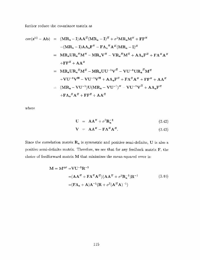
further reduce the covariance matrix as
cov(z(2) - Ab) = (MRa - I)AAH(MRa - I)H + U 2 MRaMH + FFH
-(MRa - I)AAaFH - FAaHAH(MRa - I)H
= MRaURaHMH - MRaVH - VRaHMH + AAaFH + FAHAH
+FF+H + AAH
= MRaURaHMH - MRaUU~1VH - VU-1URaHMH
+VUlVH - VU-IVH + AAaFH + FAHAH + FFH + AAH
(MRa - VU-')U(MRa - VU-)H - VU-jVH + AAaFH
+FAaHAH + FFH + AAH
where
U
V
(3.42)
(3.43)
= AAH + A2RA
=AAH1 + FAHAH.
Since the correlation matrix Ra is symmetric and positive semi-definite, U is also a
positive semi-definite matrix. Therefore, we see that for any feedback matrix F, the
choice of feedforward matrix M that minimizes the mean-squared error is:
M = MoPt -VU-R-1
=(AAH + FAHAH)(AAH + o 2 R)R 1
=(FAa + A)A~'(R + .2 (AHA)-)
(3.44)
115

Now, with M = M"Pt , we proceed to find the optimal F that leads to the minimum
MSE. The covariance matrix now becomes
cov(z - Ab) = AAaFH + FAHAH + FFH + AAH
-(FAaH + A)(I + U 2 A-Ral(AH)-1)-(FAaH H A)H
- AAaFH + FAHAH + FFH AAH - (FAaH + A)G- 1 (FAaH + A)H
= F(I - AaHG--Aa)FH + A(I - G 1 )Aa(I - AaHG-lAa) 1
(I - AaHGlAa)FH + F(I - AaHG-Aa)(I - AaHGlAa) 1
AaH(I - G- 1)A" + A(I - G-1 )Aa(I - AaHG-Aa) lAaH(I - G- 1)AH
+A(I - G-1)(I - Aa(I - AaHGlAa)-AaH(I - G 1 ))AH
- (F - A(I - G-1 )Aa(I - AaG'1Aa) 1 )(I - AaHGlAa)
(F - A(I - G-')Aa(I - AaHG-lAa) 1 )H
+A(I - G- 1)(I - Aa(I - AaHGlAa)~lAaH(I - G- 1))AH
where
G = I + aA- Ra (AH)--
Since Ra is positive semi-definite, o2A-Ral~(AH)- 1 is clearly positive semi-definite.
Therefore, all eigenvalues of G is greater than or equal to 1, which means that (I -
AaHG-Aa) is also positive semi-definite. The optimal choice of F that minimizes
the trace of cov(z - Ab) (and thereby the mean-squared error) can be found as
F = FOPt A(I - G')Aa(I - AaHG-lAa)
A(I - (I + U 2A-lRa l(A)-1)-)Aa
(I - AaH(I + 2 A-Ral(A H) 1)1Aa)l
(3.45)
116

The minimum mean-squared error in this case is
MSE tr(A(I - G - Aa(I - AaHGlAa) AaH(I - G- 1 ))AH)
= tr(A((I - G')- 1 + Aa(I - AaHAa)-AaH)l1AH)
= tr(A(I+ O2 AHRaHA +Aa(I - AaHAa)AaH -A H)
= tr(A((I - AaHAa) 1 + 2 AHRaHA)-A H)
where the simplifications in steps 2, 3, and 4 all uses the matrix inversion lemma
introduced in [63]:
(A + BCD)- 1 = A- 1 + A- 1B(C- 1 + DA- 1 B)DA-'
This completes our derivation.
To summarize, we have obtained the following results from the MMSE optimiza-
tion of feedforward and feedback matrices:
1. For any feedback matrix F), the choice of M(') that minimizes the MSE in
stage i is
M('),oPt - (F(i)Aa(Z1 ) + A)A(-) (, 2 A HA-' + Ra) (3.46)
2. With M) - M),OPt, the choice of F that minimizes the MSE in the ith stage
is
F() F('),oPt - A(I - (I + 72A~lRal(A H)-1 )-1)Aa) ()
(I - Aa(i-l)H J +2 -lRal(A)-l)-1Aa( ))
To gain some insights about this detector, which we name the MMSE Multistage IC
with feedforward Processing (MMSEMIC), we look at the initial stage, i.e. i = 1. In
this case, Aa.0 = 0 (since there are no previous symbol decisions) and thus FM1 = 0.
This gives M(M - (U2 A- 2 + R) 1 , which is exactly the linear MMSE joint detector.
This makes sense, since the MMSE linear joint detector is indeed the feedforward
117

matrix that minimizes the MSE when there is no feedback cancellation. As the
number of stages increases, the symbol estimates become more accurate and AaZ
approaches the identity matrix, we expect the performance of this receiver to surpass
that of linear MMSE joint detector.
To implement the proposed receiver in a practical system, we carry out the fol-
lowing procedures at each stage:
1. Estimate the error probability for each user in the last stage either via SIR
approximation or interleaved training sequences.
2. Compute Aaf 1 0 for the current stage (i.e. stage i).
3. Compute feedback matrix F() based on Aa(i-) and reconstruct the MAI using
b(-1) from the last stage.
4. Calculate feedforward matrix MWG based on F().
5. Apply M(W to linearly transform the matched-filter output and subtract the
reconstructed MAI from the transformation output. Send cancellation output
to quantization devices to generate symbol decisions for the current stage.
6. Repeat steps 1 through 5 at subsequent stages until BER target is reached.
Note that the main complexity of the algorithm comes from the matrix inversion
process involving Aa i 1 0 at every stage.
3.5.3 Alternative solutions with reduced complexity
Since the proposed receiver already achieves the performance of a standard linear
MMSE detector in the initial stage, we expect its performance to exceed all linear
joint detectors in later stages. Its complexity, however, also exceeds that of the joint
detectors and grows in proportion with the number of stages, primarily due to the
fact that matrix inversion, which has a complexity on the order of O((LK) 3 ), has to
be performed at every stage. To lower the complexity, in this section we introduce
118

two suboptimal solutions that have lower complexities and yet may still outperform
the linear joint detectors.
Since the complexity at each stage mainly lies in matrix inversion, we design the
suboptimal solution so that the inversion is only performed once throughout the entire
cancellation process. One sensible choice is as follows:
M (R+ (AAH)- 1 2 1 if 1 (3.48)if i > 1
F(- (R - I)AAa0 1 ) (3.49)
In intuitive terms, the resulting receiver, which we call MMSE-Feedback Multistage
IC (MMSEFIC), is a weighted multistage IC with linear MMSE detector at the ini-
tial stage. In subsequent stages, the MAI are reconstructed and subtracted from
the matched-filter output. The cancellation weights are adjusted at each stage to
minimize the MSE. In this way, the complexity of the system is similar to that of
conventional PIC with MMSE first stage.
In addition, if we do not have estimates for the background noise (which contains
thermal noise and intercell interferences) power ready, we may also use the decorre-
lator at the initial stage instead, which gives the following specification for MWz and
F('):
M( W R if i = 1 (3.50)I if i > I
F(') = (R - I)AAa( 10 (3.51)
This suboptimal receiver, which we call MMSE-Feedback Multistage IC with decor-
relating first-stage (MMSEFICD), has a complexity that is similar to the PIC with
decorrelating first stage.
119

3.6 Performance of MMSE multistage IC with for-
ward and feedback matrices
3.6.1 Asymptotic analysis
In this section we calculate the asymptotic error probability of the proposed MMSE
multistage IC with feedforward and feedback matrices for a large system with perfect
power-control and random spreading codes. This means that we assume A1 (1) =
A2(1) = .=Ak(l)= Ak+1(l)= ... =AK(L) =A, K-+ oo, N--oo and 4=K .
We first look at the minimum MSE of each stage under MMSEMIC, which can
be found as
MSE(2) = E[tr(A((I - AaHAa)1 + U 2 AHRaHA)-AH)]K
I LK + G2H ) ' ~= E[Z Ak(A((I - AaHAa, + UAHRaH AA)
k=1
1A 2 (1 - (A(')) 2 )E [ A2 1(l _A )-
1+ A2 Ak(Ra)
where Ak(Ra) is the kth eigenvalue of Ra. Simplification in the third step is based
on the perfect power control and random spreading codes assumption, in which all
users should have very similar error performance and thereby all diagonal entries in
Aa() equals to the constant A('.
Now, to further simplify MSE(), we use a convergence theorem proved in [75],
which shows that for a DS-CDMA system with random spreading codes, correlation
matrix R and =N
liK1,E F1 X1(-2
limK-+E[1 + X2Ak(R) 4 1(X,1 (3.52)
where
F(u, v) - ( U(1 + v V)2 + 1 + U(1 - v-)2 + 1)2.
120
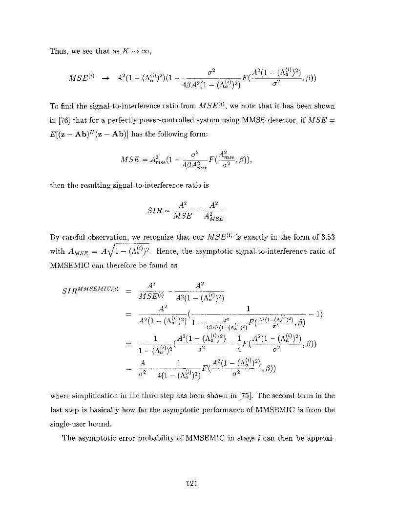
Thus, we see that as K -+ 00,
2(1 ~o2 A 2(1 _ (A('))2)AMISE~i( -+ A2(1 - -)2)(1 -) F( -(a i )
a ~4 A2(1 - (A('))2) 92-M
To find the signal-to-interference ratio from MSE(), we note that it has been shown
in [76] that for a perfectly power-controlled system using MMSE detector, if MSE =
E[(z - Ab)H(z - Ab)] has the following form:
2 A2MSE = A2 A F( (1- u A 2 )4/A~se~ s/)
then the resulting signal-to-interference ratio is
A2 A2
SIR = MSE- A2sE
By careful observation, we recognize that our MSECW is exactly in the form of 3.53
with AMSE A 1 - (A())2. Hence, the asymptotic signal-to-interference ratio of
MMSEMIC can therefore be found as
A A2 A2
SIRMMSEMIC,(i) - A 2
MSE(W A2(1 - (A('))2)
A2 ( 1-1)A2 (1 - (A)2) 1 _- 2 F( 2 (-(Aa) 2 ) ()
4#A2(1-(AMi)2) 0'2
1 A2(1 - (Ai) )2) 1 A 2 (1 - (Ai) )2)
1 - (A))2 0.2 4 .2
A 1 A 2 (1 - )2)F( A ))
O.2 4(1 - (A('))2) .2 7
where simplification in the third step has been shown in [75]. The second term in the
last step is basically how far the asymptotic performance of MMSEMIC is from the
single-user bound.
The asymptotic error probability of MMSEMIC in stage i can then be approxi-
121

mated using the standard Gaussian approximation:
PeMMSEMIC,(i) - Q(sin IR MMsEMIC(i)). (3.53)M
We next analyze the convergence behavior of MMSEMIC using error probabilities
calculated based on Gaussian approximation. Since SIRMMSEMIC,(i) is a function of
PeMMSEMIC,(i) through ASP, PeMMSEMIC,(i) is also a function of PeMMSEMIC,(i-1)
such that PeMMSEMIC,(i) _ ft(peMMSEMIC,(i-1)). To find the error probability at
which MMSEMIC reaches convergence, we just need to find out when PeMMSEMIC,(i) -
PeMMSEMIC,(i-1)
Figures 3-9, 3-10, and 3-11 show the convergence behavior of MMSEMIC as a
function of the number of stages for small, large, and over-loaded systems, respec-
tively, assuming BPSK modulation and a signal-to-noise ratio (SNR) of 7dB. The
convergence curve for WPIC (i.e. weighted PIC with MMSE optimized feedback
matrix) is also plotted for comparison. We see that, in figures 3-9(a) and 3-9(b),
which corresponds to a system with load / = 0.5 and 0.75, respectively, the error
floor for MMSEMIC and WPIC are essentially the same, except that it takes MM-
SEMIC fewer stages to reach convergence. In system with larger load, i.e. 3 = 1
and / = 1.25, which corresponds to figures 3-10(a) and 3-10(b), respectively, we see
that the error floors of MMSEMIC starts to be significantly better than WPIC, while
MMSEMIC also takes noticeably fewer iterations to reach convergence than WPIC.
For overloaded system, i.e. figures 3-11(a), 3-11(b), and 3-11(c), which corresponds to
# = 1.5, 2, and 4, respectively, we see that while WPIC performs poorly, WLIC still
exhibits a very low error-rate floor (except for extremely high load, i.e / = 4), even
though its convergence rate has slowed down significantly compared to the earlier
cases.
3.6.2 Simulation verification
The performance of the proposed MMSE multistage IC with feedforward and feedback
matrix and its suboptimal variations are verified via simulation for an asynchronous
122

10Error Probability of Weighted PIC and MMSEMIC, SNR = 7 dB, beta = 0.5
-e- MMSEMIC10'
to -' - 0 .
10'2- 10 2
0 5 10 15 20 25 30 0 5 10 15 20 25 30Number of iterations Number of iterations
(a) (b)
Figure 3-9: Error probability convergence based on Gaussian approximation for MM-SEMIC and WPIC for systems with loading (a) 3 = 0.5 and (b) # = 0.75
BPSK modulated and uncoded DS-CDMA system using random spreading codes
with a spreading gain of N = 128. The receiver operates on every frame of 800 data
symbols, including 12 training symbols for error-rate estimation.
We first look at the bandwidth efficiency of the proposed algorithms. Figures 3-12
(a)-(c) show the bit-error rate (BER) of MMSEMIC, MMSEFIC and MMSEFICD
as a function of the number of users in the AWGN channel after two, three and
five stages, respectively. The BER of the matched filter, the decorrelator, the linear
MMSE detector and the single-user performance bound are also plotted for compar-
ison. The amplitude of each user is fixed such that the individual E is 7 dB, whichNowhc
resembles perfect power control. To simulate a more realistic channel, the corre-
sponding performances in the frequency non-selective Rayleigh fading channel with
average -E= 10dB are shown in figures 3-13(a)-(c) for two-, three- and five stage
performances, respectively.
From these plots, we observe that the proposed algorithms (including the sub-
optimal techniques) clearly outperforms the linear joint detectors. Furthermore, we
observe that after three stages, the BER of the MMSEMIC is very close to the single-
user performance bound. What else is interesting is that after three stages, the
123
Error Probability of Weighted PIC and MMSEMIC, SNR = 7 dB, beta = 0.75
Weighted PIC

to' 10tError Probability of Weighted PIC and MMSEMIC, SNR = 7 dB, beta = 1.25
ghtePIC
10-1 to-
to 7 10 7
10' to'0 5 1it is 20 20 30 0 5 10 15 20 25 30Number of iterations Number of iterations
(a) (b)
Figure 3-10: Error probability convergence based on Gaussian approximation forMMSEMIC and WPIC for systems with loading (a) # = 1.0 and (b) 3 = 1.25
performance of the MMSEMIC becomes somewhat insensitive to the MAI, as the
error rate does not seem to increase proportionally with the number of users in the
system. The BER gap between the MMSEMIC and the single-user bound may be
contributed by the background noise enhancement caused by the linear transforma-
tion procedure at every stage. In addition, note that at early stages the performances
of the proposed suboptimal schemes (MMSEFIC and MMSEFICD) are far from that
of MMSEMIC. At later stages, however, the BER of these schemes, particularly MM-
SEFIC, approaches that of the MMSEMIC and the single-user bound.
We next look at the energy efficiency of the proposed algorithms. Figures 3-14(a)-
(c) show the BER vs. - for the proposed algorithms in a system with 75% loadNo
(96 users). We see that the energy efficiency of the proposed algorithms significantly
outperforms the linear joint detectors. After 3 stages, the performance of MMSEMIC
is very close to the single-user bound. Among the proposed suboptimal techniques,
the power efficiency of MMSEFIC becomes very close to that of MMSEMIC and
single-user bound at later stages.
124
Error Probability of Weighted PIC and MMSEMIC, SNR = 7 dB, beta = 1.00
ehted PIC

3.7 Chapter summary
In this chapter, we have presented two effective multistage parallel interference can-
cellation algorithms that are derived using stage-by-stage MMSE optimization. The
key difference between our detection schemes and the conventional approaches is that,
instead of assuming the symbol estimates in previous stages to be completely accu-
rate, we incorporate a weighting matrix into the detection process. The weighting
matrix is an approximate measure of the correlation between symbol estimates in
the previous stage and the true transmitted symbols. Our first algorithm applies
decision-feedback to cancel the MAI and has a complexity that is comparable to that
of the conventional PIC. Its performance significantly surpasses that of conventional
and partial PIC for both AWGN and fading channels. Our second algorithm uses
both feedforward and feedback matrices to suppress MAI, and its complexity is on
the same order as that of linear joint detection. The performance of this detector
not only surpasses that of our first scheme and the linear joint detectors but also
approaches the single-user performance bound in a small number of iterations.
125

10
10-'
a.
10-2
10-30 5 10 15 20 25 30
Number of iterations
(a)Error Probability of Weighted PIC and MMSEMIC, SNR = 7 dB, beta = 2
--- MMSEMIC+Weighted PIC
10-2
10-'0 5 10 t5 20 25 30
Number of iterations
(b)Error Probability of Weighted PIC and MMSEMIC, SNR = 7 dB, beta = 4
+ W~igted PlC10-D-
10-s -
100-
10 -
1~~ 0-5
0 5 10 15 20 25 30Nurber of iterations
(c)
Figure 3-11: Error probability convergence based on Gaussian approximation forMMSEMIC and WPIC for systems with loading (a) # = 1.5, (b) 3 = 2, and (c)
126
Error Probability of Weighted PIC and MMSEMIC, SNR = 7 dB, beta = 1.5
MMSEMICL Weighted PIC

10'
to-'
to-
to'
100
to-'
10-
to-,
10'
too
1o-'
10
1O
20 40 60 80Number of Active Users
100 120
(c)
Figure 3-12: Error probability of multistage MMSE IC vs. the total number of usersin AWGN channel: (a) 1 stage, (b) 2 stages, (c) 5 Stages
127
Performance of MMSE-based ICs in AWGN Channel, Sp Factor 128, 2-Stage
- Matched Filter Only+ Decorrelator
- M- MMSE-- MMSEFICD-- MMSEMIC+MMSEFIC
--- Single-user Bound
---
10
0 20 40 60 80 100 12Number of Active Users
(a)Performance of MMSE-based ICs in AWGN Channel, N = 128, 3-Stage
Matched Filter Only-- Decorrelator-- MMSE-
--- MMSEFICD--- MMSEMIC+MMSEFIC
- - Single-user Bound
-I'--- 0
0 20 40 60 80 100 12Number of Active Users
(b)Performance of MMSE-based ICs in AWGN Channel, N = 128, 5-Stage
- Matched Filter+ Decorrelator
-o- MMSE-e- MMSEFICD
--- MMSEMIC-- MMSEFIC
--- Single-user Bound-e
o4-
-0
0
0

Performance of MMSE-based ICs in Flat Fading Channel, Sp Factor = 128, 2-Stage10
- Matched Filter-+- Decorrelator-0- MMSE-e- MMSEFICD
+ MMSEMIC+ MMSEFIC
- Single-user Bound
-' -
2 2
20 40 60 80Number of Active Users
(a)
100 1
Performance of MMSE-based ICs in Flat Fading Channel, N = 128, 3-Stage
- Matched Filter-+- Decorrelator-0- MMSE-e- MMSEFICD-+- MMSEMIC-*- MMSEFIC- - Single-user Bound
49 o-(Y-
20 40 60 8
20 40 60 80Number of Active Users
(b)
0 20 40 60 80Number of Active Users
100 1
100 120
(c)
Figure 3-13: Error probability of multistage MMSE IC vs. the total number of usersin flat-fading channel: (a) 1 stage, (b) 2 stages, (c) 5 stages
128
10-
10
1o'
10
10
to'
10'
02
Perfornance of MMSE-based ICs in Flat Fading Channel, N = 128, 5-Stage
- Matched Filler-- Decorrelalor-0- MMSE-e- MMSEFICD-+- MMSEMIC--- MMSEFIC- - Single-user Bound
-10-49-(
I
I

Performance of MMSE-based ICs in AWGN Channel, Sp Factor = 128, 96 users, 2-Stage10
10'
10'
10
10-
10,
104 -
10-
10
10
10 10
W -e
10 -
10 -
10 -0
10,
10'
10
Cc 10'
10
10'
10'
10* -0
. - Matched Filter Only-+- Decorrelator-o- MMSE-e- MMSEFICD
+ MMSEMIC-a- MMSEFIC
- - Single-user Bound
0 2 4 6 8 10 12 1Eb/No
(a)Performance of MMSE-based ICs in AWGN Channel, N = 128, 96 Users, 3-Stage
- Matched Filter Only-i- Decorrelator-0- MMSE-e- MMSEFICD-+- MMSEMIC-a- MMSEFIC-- Single-user Bound
2 4 6 8 10 12 14Eb/No
(b)Performance of MMSE-based ICs in AWGN Channel, N = 128, 96 Users, 5-Stage
- Matched Filter+- Decorrelatora- MMSED- MMSEFICD+ MMSEMIC+ MMSEFIC- Single-user Bound
2 4 6 8 10 12 14Eb/No
(c)
Figure 3-14: Error probability of multistage MMSE IC vs. E in AWGN channel (96NoUsers): (a) 1 stage, (b) 2 stages, (c) 5 stages
129
I I
4
-----

Chapter 4
A Dual-mode Linear Multiuser
Receiver
In this chapter, we investigate the detection problem in receiver design for the uplink
a direct-sequence code-division multiple access (DS-CDMA) system. The design ob-
jective is to minimize the system computational complexity while meeting the quality
of service (QoS) requirements (such as bit-error rate(BER), throughput, and delay
constraint) of the users. Specifically, we focus on linear joint detection. We intro-
duce a dual-mode multiuser detector that dynamically switches its detection mode
between matched filter and decorrelator operations based on the channel characteris-
tics. This detector significantly reduces the overall computational requirement while
maintaining similar performance as that of the decorrelator. The switching mecha-
nism of our dual-mode detector is designed by exploiting the performance-complexity
tradeoff between the decorrelator and the matched filter.
4.1 Motivations and background
The spectral efficiency of a conventional DS-CDMA system that employs single-user
matched-filter detection suffers from multiple-access interference (MAI), or user-to-
user interference caused by non-zero cross-correlation between the spreading code
waveforms of different subscribers. Multiuser joint detector has emerged as a promis-
130

ing technique to suppress MAI. Unlike the single-user detector that performs detection
for each user individually and treats other users' signals as additive white noise, the
joint detector incorporates the information of other subscribers into consideration
while recovering data for the desired user.
The multiuser detector that leads to jointly optimal error probabilities for all users
was proposed by [74] using a maximum likelihood sequence estimation approach. The
complexity of this detector, however, grows exponentially with the number of users
and is thus unsuitable for practical implementation. Since then, most of the research
efforts in joint detection focus on the design of suboptimal algorithms that yield good
performance-complexity tradeoff [33, 42, 24, 46, 75, 84, 85]. There are grossly two
classes of suboptimal joint detectors: linear and non-linear detectors. The linear
detectors basically perform a linear transformation on the matched-filter output to
tune out the interferences, but the nonlinear detectors typically employs decision-
feedback interference cancellation.
In this chapter, we consider the class of linear multiuser detectors, which has been
shown to perform significantly better than the matched filter and is yet much simpler
to implement than a maximal likelihood (ML) detector [55, 75] (which is optimal in
terms of performance). In particular, we focus on a specific linear multiuser detector
called decorrelator, the operations of which do not require accurate estimation of the
amplitudes of the users' received signals and the background noise power. The asymp-
totic performance of the decorrelator has been extensively studied in the context of
asymptotic multiuser efficiency, bit-error rate (BER), effective bandwidth, and user
capacity [32, 54, 67, 76].
Previous studies have demonstrated that the decorrelator in general is more effec-
tive than the single-user matched filter in suppressing MAI. Its performance, however,
may not exceed that of the matched filter in certain cases due to its inherent noise
enhancement problem [76]. In particular, when the background interferences, such
as intercell interferences and thermal noise, are excessively high compared to the
MAI, the decorrelator is likely to perform worse than the matched filter. Moreover,
the decorrelator has a much higher computational complexity than the matched fil-
131

ter [34]. Even though these facts are well-known, little seem to have been done to
incorporate them into system design considerations. By exploiting this performance-
complexity tradeoff between the decorrelator and the matched filter, we propose a
new design for implementing a decorrelator-based multiuser receiver.
The main feature of our dual-mode detector is that it dynamically switches be-
tween the decorrelator and the matched-filter operations based on the interference
characteristics. Our receiver is capable of significantly reducing the consumption of
computational resources while maintaining similar performance as that of the decor-
relator. A key element in this technique is the switching criterion, i.e. when to
switch from one mode to the other. We obtain this switching criterion by compar-
ing the analytical performance between the decorrelator and the matched filter. The
effectiveness of our dual-mode detector is illustrated via simulations.
This chapter is organized as follows. We begin by briefly introducing the basic
models and structures of the decorrelator and the matched filter in section 2. We
propose our dual-mode detector in section 3 and then derive the switching threshold
in section 4 by comparing the signal-to-interference ratio of the decorrelator and
the matched filter. We present simulation results in section 5 to verify the receiver
performance. Chapter summary is given in section 6.
4.2 System model
We begin with a mathematical description of a single-cell DS-CDMA system. As-
suming K users employing antipodal signals for transmission over a frequency non-
selective additive white Gaussian noise (AWGN) channel, the received baseband signal
can be expressed as
K
r(t) = E Aksk(t - Tk)dk(t - Tk) + n(t), (4.1)k=1
where Ak and Tk are the received amplitude and delay of user k, respectively. The
function dk(t) denotes the user data waveform, where dk(t) = _'=- dk,irect(t - iT),
132

with T being the symbol interval, dk,i E {-1, 1} being the ith transmitted symbol of
user k, and rect(t) being the rectangular pulse of width T and unit amplitude. The
background additive white Gaussian noise (AWGN) with one-sided density power
density 2Np is denoted by n(t), which consists of thermal noise as well as intercell
interference, i.e. interferences from users in other cells. The function Sk(t) denotes
the spreading signature waveform of user k and can be expressed as
oo N
Sk(t ckJg(t - jT - iTb), (4.2)i=-oo j=1
where Ck,j E {-1, 1} is the value of the jth chip of user k's spreading sequence; N
is the spreading factor; Tc is the chip interval, i.e. T = NTc; g(t) is the chip pulse,
which is assumed to be rectangular for the convenience of analysis and simulation;
The energy of g(t) has been normalized such that fTb ISk(t)!2dt = 1.
First we look at linear joint detection for a symbol-synchronous DS-CDMA system,
i.e. Tk is zero for all k. This model applies to the uplink with very tight timing control,
an example of which is the time-division synchronous CDMA (TD-SCDMA) system
developed for 3rd generation wireless system in China [66]. To detect the ith symbol
of the kth user, the receiver first performs matched filtering for user k over the interval
[iTb, (i + 1)T]. The detection for the ith symbol for all users is thus equivalent to
passing r(t) through a bank of matched filters. The output of this filter bank, which
we denote as y = [Y1 Y2 ... yKIT, forms a set of sufficient statistics for the detector
decision on the received symbols. Each element of y can be found as
Yk i1)Tb r(t)sk(t)dtJiTb
K (4.3)=Akdk,i ± ) Pk,jAjdj,i + nk,
j=1 ,j~k
where nk is the projection of n(t) on Sk(t) and Pk, = f(i±1)T sk(t)sj(t)dt is the cross-
correlation between the kth and jth users' signature waveforms. The middle term
of y is the MAI from other users on user k, which is clearly caused by the nonzero
133

cross-correlations between the users' signature waveforms. Furthermore, we see that
y = RAd + n, (4.4)
where R is a K-by-K correlation matrix with elements Rkj - Pk,, A is a diagonal
matrix with Ak,k = Ak, d = [di,j d2 ,i ... dK,i ]T is the data vector, and n = [n, n2 ...
nK ]T is the noise vector.
With linear multiuser detection and hard-limited decision, the output decision for
user k's symbol is made as dk,i = sgn(zk) where
z = Ly, (4.5)
L is a linear transformation matrix depending on the type of detector that is used.
For the conventional matched-filter detector, L is a K by K identity matrix. For the
decorrelator, L = R+, where R+ denotes the Moore-Penrose pseudo-inverse of R.
When R is nonsingular, R+ equals to R-1 . The decorrelator essentially performs a
linear transformation with the intention to completely eliminate MAI. It has been
shown that the decorrelator achieves the optimal near-far resistance as long as R is
nonsingular, i.e. user signature waveforms are linearly independent of each other [75].
We now develop a similar model for an asynchronous CDMA network, which is
applicable to the uplink of a cellular system without timing control. In contrast to the
symbol-synchronous case, user k's delay, Tk, is no longer zero but a real number that
is distributed between zero and T and is independent of the timing of other users.
To minimize the decision delay, we look at one-shot detectors, which means that the
detection of the ith bit of user k is based only on the received signal over the interval
[Tk + iTb, Tk + (i + 1)T]. The one-shot detection is optimal for the matched-filter
detection but suboptimal for the decorrelator detection [75].
Without loss of generality, we consider the detection of the ith bit of user 1, and we
assume that T1 = 0. We therefore want to look at interval [iT, (i + 1)T] for di,,. Due
to the assumed asynchronism, the interference caused by each user may contribute in
multiple dimensions. We subsequently rewrite r(t) over the time interval of interest
134

2K-1
r (t) = E Akdk,isk(t),k=1
where d1,i = d1,j, 1 1(t) = s1(t), and for k 0 1
= dk,i1, d2k+1,i = dk,i
Sk(t-Tk) t E [ib, iTb Tk
0 otherwise
Sk(t - Tk), t E [iTb + Tk, (i + I)Tb]
0 otherwise
A set of sufficient statistics for the one-shot detection over the interval [iTb, (i +
1)Tb] is 9 = [ l Y2 ... Y2K-1]T where
k = /(i+1)Tk iTb
We see that, similar to the synchronous case,
y =R Ad + n, (4.7)
where now R is a (2K - 1) by (2K - 1) correlation matrix with elements Rkj =
Pkj = f(i+s)Tb Sk(t)Sj(t)dt.
The estimate of the ith symbol of user 1 is obtained as d1,j= sgn(zij) where
(4.8)
where L is an identity matrix for the matched-filter detection, and L = R+ for the
decorrelator. Here, again, we see that the decorrelator can completely eliminate MAI
for user 1 as long as the one-shot cross-correlation matrix R is nonsingular.
135
as
t E [iTb, (i + l)Tb], (4.6)
d2k,i
s2k(t)
s2k+1
T(t)§k(t)dt.
z = Ly ,

4.3 Architecture of the dual-mode detector
Even though the decorrelator is able to effectively suppress MAI, its performance
suffers from a problem known as noise enhancement. The reason is that during
the linear transformation process, the noise component in the received signal is also
being scaled by the inverse of the correlation matrix. This has been shown to result
in a greater noise power [75]. Consequently, in the case where the background noise is
stronger than MAI, the decorrelator is likely to perform worse than the matched filter.
In particular, [76] showed that for a DS-CDMA system with random spreading codes
and an optimal choice of spreading gain, the spectral efficiency of the decorrelator
is greater than that of the matched filter only if the average E of all users in the
system exceeds 5.2 dB.
In terms of computational complexity, the decorrelator operation requires signif-
icantly more computational resources beyond the matched filtering. It is shown in
[34] that for a standard implementation of the full-decorrelator in an asynchronous
CDMA system, the total number of operations required beyond the matched filtering
is at least on the order of cubic of the number of users. It is therefore inefficient to
apply the decorrelator in an environment where it does not significantly outperform
the matched filter.
These observations prompt us to propose a dual-mode multiuser detector that
dynamically switches the detection mode between the decorrelator and the matched-
filter operations. The overall architecture and operations of this dual-mode detector
can be easily understood by examining figure 1. The receiver first processes the
incoming signal with a bank of matched filters. Next, it performs certain necessary
estimations using the output of the matched filter. These estimates are then used
to decide whether to perform multiuser detection (MUD). If so, the decorrelator
transformation will be performed. Otherwise, the receiver bypasses the decorrelator
operations, and the output of the matched filter is used for the symbol decision. The
detection mode is decided on a symbol-by-symbol basis for each user.
The key idea here is that the decorrelator operation for all users will be performed
136

received Matched _ Do Yes Decorrelator Decisionsignal FilaterDsina _"Filter Dea UDetection
Channel
Estimation
Figure 4-1: Structure of the dynamic dual-mode linear multiuser receiver
only if the MAI dominates other background interferences for a significant number of
users. Note that in a realistic cellular system, the background interferences for each
user come not only from the thermal noise but also from other sources such as inter-
cell interferences, which can be quite strong at times. Also, due to multipath fading,
the amplitude of the received signal of each user may vary over time significantly. We
thus expect that there would be a significant portion of time during which the decor-
relator does not outperform the matched filter. The use of this dual-mode detector
therefore has the potential of significantly reducing the computational requirement
while maintaining similar performance as that of the decorrelator, if not better.
4.4 Switching criterion
In this section, we describe how to make decisions about the detection mode, which
is the key element of this dual-mode receiver. We first analyze and compare the
performance of the one-shot decorrelator and the matched filter, based on which
we then decide our design parameters for the switching block that determines the
detector mode.
We first look at the performance of the decorrelator, which has been extensively
studied[32, 67, 72, 75, 76, 77]. Most of the existing works focus on the asymptotic
behavior of the decorrelator by letting the spreading factor N and the number of
users K go to infinity while fixing the ratio between N and K at a finite value. Here,
137

instead of analyzing the asymptotic behavior, we derive a performance bound on
the output signal-to-interference ratio (SIR) of the one-shot decorrelator detector for
finite K and N.
We first look at a two user synchronous system. In this case, the matched-filter
output for users 1 and 2 can be explicitly expressed as
y1 = Aibi+A 2pb2 +ni
Y2 = A2b2 + A1pb2 + n2
where we let P = P1,2 to denote the cross-correlation between the spreading codes of
users 1 and 2. If we express the matched-filter output into vector form y = RAb + n,
the correlation matrix is
R = P
p 1
The inverse of R can be found as
R-1 2 -P
1 - p2 -
The output of the decorrelator transformation is z = R-ly [ziz 2 ]T, the elements
of which can be found as
zi = Alb, + ni -pn21 - p
Z2 = A2b2 + n2 -
1 - p2
Without loss of generality, we look at the performance of user 1. We see that
before decorrelator, the signal-to-interference ratio (SIR) of user 1 is
IR A2SIR, = 1 (4.9)
Al2+NP
138

After decorrelator, the SIR becomes
A112SIR ecorr - I
E[("n2 )2]
A (1 -p 2 )2
E[n,~ + Elr2]P - 2pE[niri2] (4.10)A (1 - p2 ) 2
N
The tradeoff here is that even though the MAI has been eliminated, the back ground
noise has been enhanced by a factor of 1 - p2 . Or equivalent, we can say that the
user pay a penalty of 1 - p2 in the signal power for using decorrelator.
If we compare SIR'f and SIR1eco", we see that the decorrelator will benefit user
1 in terms of SIR only if
A2 (1- p 2 ) A 2
Np A p2 +N
Or equivalently
A2 1
p p2
which means that the decorrelator outperforms matched filter in terms of SIR only if
the signal-to-background-noise ratio (SNR) of user 2 exceeds 11P2*
Using similar procedure, we can show that user 2 will benefit from decorrelator
detection only if
A 1> 1N 1 - p2
We now extend the analysis to a system with K users. Without loss of generality
and for notational convenience, we again analyze the SIR for user 1. We state our
main results in this section and present the proof in appendix B. Let us first consider
a synchronous CDMA system with nonsingular correlation matrix R. The soft output
139

of the decorrelator detector for user 1 in this case is
K
z= Adi + ZR--ikn, (4.11)k=1
where nk is the kth element of the noise vector. The following theorem gives a lower
bound on the SIR of any user:
Theorem 4.1 Let SIR dco denote the output SIR of the decorrelator receiver for
user 1 in a symbol-synchronous CDMA system where the spreading sequences of all
users are linearly independent of each other. Then
A 26r (R)SIR decorr > I min(RI N (4.12)
where crmzn(R) is the minimum singular value of R, the correlation matrix of the user
signature sequences, and Np is the noise power.
Similarly, for an asynchronous CDMA system using the one-shot decorrelator
detection, we obtain the following corollary:
- decorrCorollary 4.1 Let SIR1 denote the output SIR of the one-shot decorrelator
receiver for user 1 in an asynchronous CDMA system. Assuming that the one-shot
correlation matrix R is nonsingular, then
dccorr A 2a (SIR1 N / " (4.13)
The interpretation of theorem 4.1 and corollary 4.1 is that even though the decor-
relator has eliminated MAI completely, its performance is now limited by the noise
enhancement, and the worst-case noise enhancement factor is the inverse of the min-
imum singular value of the cross-correlation matrix.
So far, we have assumed that the cross-correlation matrix involved in the de-
tection process is nonsingular. This condition can be maintained for a synchronous
140

CDMA system as long as the number of users is less than the spreading factor.
For an asynchronous CDMA system, however, the non-singularity of the one-shot
cross-correlation matrix is not guaranteed even if the number of users is less than
the spreading gain [75]. This is because each user in such a system is capable of
contributing interferences in multiple dimensions. Theorem 4.2 subsequently gives
a lower bound for the decorrelator SIR in the case where the one-shot correlation
matrix is singular.
decorrTheorem 4.2 Let SIR1 denote the SIR of the one-shot decorrelator receiver
for user 1 in an asynchronous CDMA system with singular one-shot correlation matrix
R. Then
decorr AlMiR Y1 M 2 A 2 (Np) (4.14)
Ej2 MJ A +-i
where &min(R) is the minimum nonzero singular value of R. Mij - vi'vj, where vi'
is the transpose of vi, which is a length-L vector that contains the first L components
of the ith right singular vector of f 1, where L is the number of nonzero singular
values in k.
The bound in theorem 4.2 leads to another fundamental insight on the decor-
relator. It shows that when the correlation matrix is singular, the decorrelator's
performance suffers not only from the noise enhancement but also from the resid-
ual MAI and an attenuation on its own signal power. It is widely believed that the
decorrelator generally performs worse than the matched filter in this case [76].
We now look at user l's SIR if only the matched-filter detection is used. This SIR
can be expressed as
A 2SIR7n - (4.15)
1 2j A? + Np
1 The ith right singular vector refers to the ith row of V, where R = VEVT is the singulardecomposition of R.
141
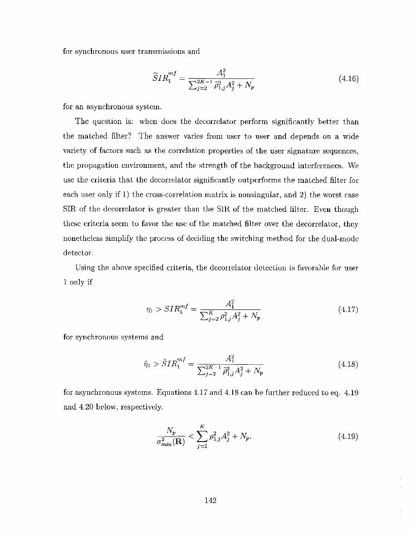
for synchronous user transmissions and
SI ' = 2 A- (4.16)1 =K2 ,jA? + Np
for an asynchronous system.
The question is: when does the decorrelator perform significantly better than
the matched filter? The answer varies from user to user and depends on a wide
variety of factors such as the correlation properties of the user signature sequences,
the propagation environment, and the strength of the background interferences. We
use the criteria that the decorrelator significantly outperforms the matched filter for
each user only if 1) the cross-correlation matrix is nonsingular, and 2) the worst case
SIR of the decorrelator is greater than the SIR of the matched filter. Even though
these criteria seem to favor the use of the matched filter over the decorrelator, they
nonetheless simplify the process of deciding the switching method for the dual-mode
detector.
Using the above specified criteria, the decorrelator detection is favorable for user
1 only if
A 21 > SIR± N (4.17)
K2 A? + Np
for synchronous systems and
1 > SIR = 2K-1 1 +N (4.18)Ej2 P ,jAj + N
for asynchronous systems. Equations 4.17 and 4.18 can be further reduced to eq. 4.19
and 4.20 below, respectively.
Np K
r2 R)Aj +2. (4.19)min (P) j=2
142

N 2K-1
2 ~ 1 2'Aj + . (4.20 )min(R) j=2
Eqns. 4.19 and 4.20, together with the non-singularity constraint on the correlation
matrix, can subsequently be used for our switching criteria so that the decorrelator
detection will be performed only if the corresponding criteria are met. The intuition
here is that the decorrelator detection should be performed only if the worst-case
noise enhancement incurring from the decorrelator operation is less than the total
interferences before the decorrelator detection.
There is, however, one problem for using eqs. 4.19 and 4.20 as the switching
criteria. As mentioned before, this decision somewhat favors the use of the matched
filter over the decorrelator, as we are comparing the worst case SIR of the decorrelator
with the exact SIR of the matched filter. To address this problem, we modify eqs.
4.19 and 4.20 by replacing the minimum singular value of the correlation matrix with
reciprocal of the average of all singular values of R-'. This average can be computed
as the average of the reciprocals of the singular values of the correlation matrix R.
Since R is symmetric and positive semi-definite, singular-value decomposition here is
identical to eigen decomposition [63]. The average singular value of R- 1 can therefore
be found by averaging over the reciprocals of the eigen-values of the correlation matrix
R. Eqns. 4.21 and 4.22 show the modified criterion that we eventually use for our
dual-mode detector in synchronous and asynchronous CDMA systems, respectively.
Np(trace(R-1)) 2 K
K 2 N A , (4.21)j=2
Np(trace(R-1 )) 2 2K-i
(2K - 1)2 < P A + N, (4.22)j=2
where trace(R-') is the sum of all diagonal elements in the inverse of R, which can
143

be found as
rank(R) 1trace(R-1 ) (R), (4.23)
where rank(R) is the rank of matrix R and Aj(R) is the ith eigenvalue of R.
Even though the average eigenvalue of correlation matrix can be readily estimated
with the knowledge of the spreading waveforms and the transmission delays of all
users, the process is as complicated as finding R-1 or Rl- 1. This defeats the purpose of
the dual-mode detector. Fortunately, we can use the following proposition to further
simplify our decision process for a system with random spreading codes, which apply
to realistic DS-CDMA system using long pseudorandom spreading codes, such as in
the IS-95 and CDMA2000 reverse link. This proposition has been proved in [6] and
can be stated as:
Proposition 4.1 Suppose that K users employ direct-sequence spread-spectrum
waveforms with N chips per symbol. Let
Klim - = E (0, 0)
K->oo N
Suppose that the choice of signature sequences is completely random: the sequences
assigned to each user are independent, and all binary sequences are equally likely.
Then, the percentage of the K eigenvalues of R that lie below x converges (as K -+ oc)
to the cumulative distribution function of the probability density function
bW 1[+x(x) + [x-a]+[b - x]+ffl(x) = [1 - #2]+(x)x
where
[z]+ = max{0, z},
144

and
a =(1 - /)2
b =
Moreover, if 0 < 1, the smallest eigenvalue converges almost surely to a.
Using this lemma, we proceed to simplify the process of finding average eigen-
values of R for # < 1 in a large system as follows:
E[R] - 00 1f(x)dxAi(R) fo X
f[ b {x - a)(b - x)
a 27rx 2 dx1
1-#3
where the explicit express for the definite integral can be verified using [22] for / < 1.
Hence, for a system using pseudorandom (PN) spreading code that has period
longer than the spreading factor, we consider decorrelator operation to be desirable
for user 1 if
K1 2 <ZPE2 ±N
Sj=2 < ( pjAj + N(4.24)
for synchronous system and
1 2K-1
Np( )2 ] 2' Ai + (4.25)j=2
for one-shot detection in asynchronous system, where = K
Furthermore, for a system with random spreading codes, we have shown earlier
in chapters that Z 2 E pkk] = K1 for all j y4 k in a synchronous system and that
2K21 E[p,2] = K-1 for all j :A k for a symbol asynchronous but chip synchronous
system. In addition, if we employ perfect power control, we have A1 = A2
145
AK = A. In this case, i.e. with perfect power control and random spreading, we can
further simplify our threshold for performing decorrelator to be
N 1 K - 1N(_)2 < A2 +N ~A2 +N
A 2 2 - A (4.26)
NP (1 - 1)2
for both synchronous and asynchronous system. This threshold actually echoes with
our results for the two-user system earlier. It means that decorrelator detection should
be performed only if the signal-to-background-noise ratio of each user is larger than
a certain threshold, in which case the noise enhancement does not create as much
degradation as MAI. In addition, the non-singularity constraint on the correlation
matrix, which translates to 0 < 1, should also be satisfied for performing decorrelator
detection.
In addition to the average eigenvalue, two additional parameters may need to be
estimated for the dual-mode detector: the total MAI and the background interference
power, which includes thermal noise and intercell interferences. Assuming that we
have a method to obtain a rough estimate of the signal amplitudes for each user (such
as via a pilot signal [2]), MAI and background interference powers can be estimated
as follows. Since the receiver knows the pair-wise cross-correlations among all users,
we can use these correlation values and the amplitude estimates to calculate the total
MAI power for the user of interest. We can also find the total interference powers
at the output of the matched filter by using our amplitude estimates. Then, we can
subtract the the MAI power from the estimated overall interference power to estimate
the background interference power. Note that in order to decide the detection mode,
we do not need very high accuracy in the estimation of amplitudes and interferences.
To summarize, for a system with imperfect power control and random spreading
codes, we can use eqs. 4.24 and 4.25 to decided if decorrelator detection is suitable for
a particularly user. For a perfect power controlled system, eq. 4.26 can be employed
for both synchronous and asynchronous systems. If the receiver finds that decorrelator
detection is favorable for over half of the user population, then its operation will be
146
performed. Otherwise, the symbol decision for each user will be based on the matched
filter output.
4.5 Performance verification
Numerical simulations have been performed for an uncoded system (i.e. no channel
coding) with BPSK modulation to verify that the proposed detector with our de-
rived decision criterion can achieve similar performance as that of a full decorrelator
detector while minimizing the overall complexity. We use a frequency-nonselective
and slow-fading channel model, which means each user's signal arrive at the receiver
via a single-path with Rayleigh distributed attenuation. We also assume that the
receiver for every user has perfect knowledge of the signature waveforms, delays, and
amplitudes of all users in the system. All users are spread by a factor of 64 with ran-
dom spreading codes. The background interferences are modeled as additive white
Gaussian noise with varying power over time such that the nominal signal-to-noise
ratio for every user is uniformly distributed between 0 and 12 dB. The variations in
the background interference power mainly intend to model the intercell interferences
from the neighboring cells with different loadings over time.
Figures 4-2 and 4-3 compare the error performances between the dual-mode de-
tector, the one-shot decorrelator, and the matched filter for synchronous and asyn-
chronous CDMA systems, respectively. The bit-error rate (BER) averaged over all
users is plotted against the number of users in the system. Each point is averaged
over 1000 trials, and within each trial each user transmits 100 symbols continuously.
We see that the performance of the dual-mode detector is very close to that of the
decorrelator using our decision criterion. Also, for the asynchronous case, because
the one-shot correlation matrix occasionally becomes singular, the dual-mode detec-
tor actually performs much better than the decorrelator in some cases. Furthermore,
it is worth noting that throughout the entire simulation, the dual-mode detector
only operates in decorrelator mode 40% of the time, which is a significant saving in
processing power.
147

BER of the Dual-mode Detector, the Decorrelator, and the Matched Filter for a Synchronous CDMA System
2 4 6 8 10Number of active users
12 14 16
Figure 4-2: Comparison of BER between the dual-mode detector,and the matched filter in a synchronous CDMA system
the decorrelator
BER of the Dual-mode Detector, the Decorrelator, and the Matched Filter for an Asynchronous CDMA System0.11 1
122 4 6 8 10Number of active users
Figure 4-3: Comparison of BER between the dual-modeand matched filter in an asynchronous CDMA system
148
0.1
0.09-
-*- Dual-mode Detector--E- Decorrelator- - Matched Filter
VI0.08-
.cwCO
0.07
0.06-
0.05
n
0.
ImW 0.Mt
0.1 -
09-
08-
07
06-
0.
0.
n14 16
detector, the decorrelator
04' 1 1 1 1 1 1 1
I
.
.0 0
Nonetheless, we note that there are still small differences between the BER curves
of the dual-mode detector and the decorrelator. This gap may be further narrowed by
using a switching method that favors more decorrelator operations. The subsequent
performance increase, however, will come at the expense of higher computational
complexity.
4.6 Chapter summary
In this chapter, we designed a dual-mode linear joint detector that dynamically
switches its detection mode between the matched filter and the decorrelator. Our
switching criterion is obtained by comparing the error performance of the decorre-
lator with that of the matched filter. We showed through simulation that the error
performance of the proposed receiver is capable of approaching the bit-error rate of
the decorrelator while only performing the decorrelating operation 40% of the time.
149

Chapter 5
Summary and Future Research
Directions
Overall, this thesis has addressed three topics. First, we have analyzed and com-
pared the error performances of two promising variable-rate DS-CDMA transmission
techniques, namely MCD- and VSG-CDMA for AWGN, flat- and multipath-fading
channels. Second, we have derived a class of parallel multistage interference cancellers
that exhibits superior performance under the given complexity constraints. Third, we
have presented a dual-mode linear multiuser detector that achieves the performance
of a decorrelator while consuming significantly less processing power. In this chapter,
we briefly summarize the results and point out future research directions for each of
the three areas.
5.1 Multirate DS-CDMA transmission techniques
5.1.1 Summary
In this thesis, we compared the error performance of multicode (MCD) and variable-
spreading gain (VSG) transmission in the uplink of a DS-CDMA system for a dual-
rate system with one high-rate user and multiple low-rate users. We showed that
for AWGN channel, at moderately high signal-to-noise ratio, the VSG high-rate user
150

has a lower error probability than the MCD user when the number of low-rate users
is small. In a flat-fading channel, however, VSG and MCD high-rate users exhibit
identical error rate, since fading smoothes their interference distributions. For a
multipath fading channel, we showed that if the delay spread of the channel is small,
then the SIR of the VSG user is worse than that of the MCD user. The reverse is
true for channels with large delay spread. We also showed that while for a two-path
channel the SIR is a good indication of tradeoffs in error probability, in channels
with three or more paths a better SIR does not imply a lower bit-error rate. This
phenomenon is mainly due to the asymmetric distribution of the correlated multipath
interferences in channels with more than three paths.
5.1.2 Potential follow-up studies
There are a number of future research possibilities to follow-up our study. First, we
did not make a definite conclusion on the exact difference between the bit-error rates
of MCD and VSG user for channels with three or more paths. Instead we observed
that in this case the Gaussian approximation of error probability using SIR may
significantly deviates from the exact error probability in some cases. A derivation for
the general expression of the exact error rate of MCD and VSG user in multipath
channels would nicely complement our research.
Second, in the thesis, we assumed that the user signature sequences are random.
The comparison outcomes can significantly change if this assumption has been mod-
ified. For instance, it has been shown that if the MCD user only uses Walsh codes
but no random code scrambling, its performance in multipath channels will be sig-
nificantly worse due to the poor autocorrelation property of Walsh codes [18]. It
is also possible that the use of certain deterministic sequences with better auto- and
cross-correlation properties, such as the ones proposed in [64], can provide MCD users
better performance than VSG users.
Third, we assumed the user interferences from other cells to be additive back-
ground noise and did not consider interactions between neighboring cells in detail. In
reality, a subscriber at cell edge would cause a lot more interferences to the neighbor-
151

ing cells than one that is near the cell center. Thus, it would be interesting to study
the spectral efficiency of MCD and VSG for a general cellular network (i.e. from a
multicell perspective) by taking into account both large-scale and small-scale propa-
gation effects. In addition, our error-rate analysis can be extended to systems with
more than two rate classes, which is likely to happen in practical multirate CDMA
networks.
5.2 Multistage parallel interference cancellation
5.2.1 Summary
In the area of nonlinear multiuser joint detection, we presented two effective multi-
stage weighted parallel interference cancellation algorithms based on stage-by-stage
MMSE optimization. The first algorithm is equivalent to a conventional PIC con-
catenated with a weighting matrix and has a complexity that is on the same order as
that of a conventional PIC. Its error performance significantly surpasses that of the
conventional PIC, particularly for systems with large user population. The weighting
matrix provides an approximate measure on correlations between the previous-stage
symbol estimates and the true transmitted symbols. Our second algorithm is more
complex than the first technique such that it uses a feedforward matrix and a feedback
matrix to suppress the MAI together. Both matrices are derived to jointly minimize
the mean-squared cancellation error in each stage. We show that the performance
of this algorithm is not only significantly better than our first algorithm but also
approaches the single-user performance bound using just a few stages. Its complexity
is only on the order of what is required for linear joint detection.
5.2.2 Future research possibilities
While our first algorithm and its suboptimal variations are simple and can be read-
ily implemented in practice using today's technology, the complexity of our second
technique is still quite high for practical implementation. To reduce the complexity,
152

adaptive algorithms can be used to derive the feedback and feedforward processing
parameters. However, simple adaptive algorithms, such as the well-known least-mean-
square (LMS) algorithm, have slow convergence and can become unstable when the
operating condition suddenly changes. For instance, we observed from simulations
that if the LMS algorithm is applied in the feedback, its robustness is very sensitive
to the number of users. If the coefficients of the LMS is tuned for a system with a
large number of users, then its performance will be poor when the number of users
becomes small (due to excessive background noise enhancement). The search for a
class of reliable and cost-efficient adaptive implementation for both feedforward and
feedback matrices is therefore an interesting topic to pursue.
Another interesting idea that can be explored is to apply multistage interference
cancellation to coded systems, in which case we can use the output from the channel
decoder as previous stage data estimates. In this case, the error probability of the
previous stage data bits may be smaller than the corresponding symbol error rate
in a uncoded system. A challenge here is to develop a solution that designs the
interference cancellation process and the decoder structure jointly to optimize the
error performance while maintaining a reasonable complexity.
In addition, we assume the symbol decision devices (after the joint detector) out-
put hard-decision symbols in each stage. It has been shown that using soft-decision
quantizers with partial PIC can gain significant performance improvement compared
to the coupling of partial PIC and hard-decision estimates[62, 811. For our proposed
receivers, we can also apply soft-decision quantizers to decide the symbol estimates in
each stage and use this condition to re-derive the MMSE feedforward and/or feedback
matrices to obtain further performance improvement.
153

5.3 Dual-mode linear multiuser detector
5.3.1 Summary
Finally, this thesis introduced a dual-mode linear multiuser detector for the base-
station receiver that dynamically switches its detection mode between the matched
filter and the decorrelator. We derived a set of switching criterion and showed through
simulation that this receiver is capable of approaching the performance of a decorrela-
tor but using much less processing power. With firmware and DSP implementation,
this detector is capable of leading to efficient resource sharing at the base-station
receiver.
5.3.2 Future research possibilities
Two follow-up studies can be done for this dual-mode receiver. First, the threshold
that we used in this thesis is not necessarily optimal. It is possible to find other
simpler or more effective switching criteria that can push the performance of this
detector even closer to that of the decorrelator without significantly increasing the
complexity. Second, the same philosophy can be extended to other types of detec-
tors such as the linear MMSE detector or even the nonlinear interference cancellers
to reduce complexity. Furthermore, we can develop a nonlinear interference can-
celler that dynamically switches between successive interference cancellation (SIC)
and parallel interference cancellation (PIC) according to differences in the user's re-
ceived power to take advantage of both detection schemes. The benefit in this case
is error-performance optimization rather than complexity reduction.
154

Appendix A
Derivation of the weighting matrix
for MMSE-based Multistage
Interference Cancellers
In this appendix, we derive the weighting matrix Aa(i) for a DS-CDMA system using
M-ary phase-shift-keying (M-PSK) modulation, where M is a power of 2. Following
our derivation of the MMSE feedback matrix in chapter 3, we see that at stage i, the
weighting matrix used in the cancellation process is
Aa(i-l) = E[b (i-1I)H ]. (A. 1)
where, as specified in section 5.2, b is the vector of transmitted symbols and b(- 1)
is the vector of the corresponding detected symbols at stage i - 1. We solve for the
diagonal and off-diagonal terms of Aai separately. First, assuming all symbols in the
M-PSK constellation are transmitted with equal probability, we evaluate the diagonal
terms, i.e. A,' (m, m), as follows:
M-1A(' (m, in) = E = jE[bmbb)Hm e'W]
n=O
155

To find E[bmbM)H bim = _ , we look at the decision regions for M-PSK constellation
as shown in figure A-1. For any transmitted symbol bm, if it is detected correctly,
mbm')H = 1. If a mistake is made, however, the detector output has most likely
moved into the decision regions of bm's closest neighbors. The symbol estimate b$~2
will therefore most likely be decoded as bme m or bmeJ-i. It is also possible for
0) to be decoded as other symbols besides bm, bme' , and bme' 3, but we assume
the probability of such event happening to be zero, since in reality, the probabil-
ity that the detector output falls outside the closest neighbors of bm is extremely
small. In addition, We assume that if an error is made, the detector falls into the
two closest (neighboring) decision regions with equal probability. Thus, we evaluate
E[bmb(')HlejT] as
[bm0)' H bm 2nrThLM~/I~ b~ , bHPT(b(i) bm) + bmbHeij r I Pr : bm)~ m 2+b M bH - Mm22
=Pr(b() bm) + IPr #bm) (ei ti + e -i m
Cos/27re rL (m # bn)= 1 - (1-
Since E[bbMs) bm = e M] does not depend on n, we see that
(i, M)M-1
= Z:1E[bmb)Hb -e3 n-
I - (1 - cos -)Pr($Q $ bm)n= M
= -( s )Pr( I b\)M
Since Pr($(2 # bm) is basically the error probability for bm, we can estimate this term
on a user-by-user basis. Among the diagonal terms of Aa('), the first K terms measure
the reliability the first symbol estimate for users 1 through K, the second K terms
measure the accuracy of the users' second symbol estimates, and so on. Therefore,
if we let bk(l) denote the lth symbol transmitted by user k, we have A((m, m) =
156

(i-1) WiE[bk(l)bk(l) ] for m = (K - 1)1 + k. It is reasonable to assume that Pr(bk(l)
bk(l)) = Pe for all 1, where Pe(') is the error probability of user k is stage i.k k
Subsequently, we find the diagonal terms of the weighting matrix as
A) (m, m) = 1 - (1 - cos -)Pe(, m = K(l - 1) + k, l, k c {1, 2, ... L}. (A.2)
or equivalently
diag (Aa) = [w i)wtiT ... ]
where w(') - 1 - (1 - cos Z)P(i) such that P() = [Pegi, Peg, ... Pe]T.
We proceed to derive the off-diagonal terms. To make the derivation process
clear, let's first consider a synchronous CDMA system where each user transmits one
symbol only, i.e. L = 1 and p(O ) - p. In this case, Aa(') becomes a K-by-K
matrix, and its diagonal vector equals to w(). Each off-diagonal term of Aa(i) can be
found as
AW (m, k) = E[bmbli)H1, m A k
which measures the effect of user m's symbol on user k's detector output. We see
that such effect is caused by the MAI from user m on user k. For i > 1, i.e. after
at least one cancellation, the effect of MAI becomes small for sufficiently accurate
symbol estimates. Thus, for i > 1, we approximate A()(m, k) to be 0 for all m y
k, km E {1, 2, ... K}. For the initial stage, i.e. stage 1, where the symbol decisions
are made solely based on the matched filter output, the effect of MAI can be quite
strong. In this case we choose to compute A1 (m, k) as follows.
First, we consider the case M = 2, i.e. a binary phase-shift-keying (BPSK)
modulated system. Assume the transmitted symbols are equally likely being 1 or -1,
157

we have
A()(m, k) = E[bmb(l)H]1 1
= 'E[bb('lbk = 1] + E[bmb(1 !bk = -1]2 k2 k
Due to symmetry in the constellation, E[bmb"1 jbk = 1] = E[bmbij)bk = 1] =
E[bmb()], it is therefore sufficient to evaluate E[bmb I|bk = 1], which can be expressed
as
E[bmb(bIbk = 1] E[b)b 1 b 1] E[b(1)lb - 1, bm = -1]k2 kM2 kk r
where we solve the first term on the right hand side as
E[b(01 b = 1, bm = 1] Pr(b1 ) = blb 1, bm = 1)- b-bk = 1,bm 1
-Pr (b C) = -bkb = 1 bm = 1)
Ak + Anp(O= 1-2Q( Ak±A(0)
1J2 + MAIk - (Apk)2
where
K
MAlk (( Am(l)po )2.
m=1,m:k
Note that in calculating the error probability for bk, we applied standard Gaussian
approximation to treat the MAI from all users other than user n as white Gaussian
noise, which is valid for a system with large spreading gain, perfect power control,
and random spreading codes. Similarly, we find that
E[Wb) Ibk = 1, bm = -1] = Pr(bW) = bk Ibk = 1, bm = -1)
-Pr(b C) = -bbk = 1, bm = -1)
Ak An p(= 1-2Q( A)m
Or+ MAIk - (Anpk)2
158

To put the terms together, we find that
A1 (i, k) = E[bm(b1)H] = E[bmb(') bk - 1]
Ak+ Ap(O)
2+ MAIk - (A p )2
Ak- A, p ()
2+ MAIk - (A p( )2
2
Ak+ Anpk-Q( k)
0-2+ M AIk - ( AnPk)2
which completes our derivation for the weighting matrix for BPSK modulated systems
with synchronous transmission.
To extend the result to a general M-PSK system where M is a power of 2, we
evaluate Aa (' (m, k) as
A(') (n, k) = E[bmb(l)H1M-1
E 1 E[bmb 1)HM~ M
k 2kbke M eIw
An example of M-PSK constellation is shown in figure A-1 for M = 8. Due to sym-
Im
Re
Figure A-1: M-PSK signal constellation for M=8
159
= -(I - 2Q(2
I(1 - 2(2
Ak - Ap
v.2 + MAIk - (Anpk))
metry of the constellation and the conjugate symmetric product in the expectation,
we see that E[bmbI)H k ei ] is the same for all k E {0, 2, ... M - 1}. Thus,
without loss of generality, we evaluate E[bmb b)H _ = 1], which corresponds to k = 0
and can be evaluated as:
M-1
E[bm, b()HI bk =1] = es E [b(')Hbm ei , bk 1m=m
M-1
~ ei (Prob[b1)H - bm = M bk = 11 (A.3)m=O
+ eifPr ob[)H __1r bk 1]
+ e- MProb[b) - - bm = e bk = 11)
where the approximation in the second step assumes that, if a symbol error is made,
it is most likely for the received signal to fall into the decision regions of the two
closest neighboring constellations.
The key to evaluate E[bmb(l)Hbk = 1] lies in finding the three probability terms in
eq. (A.3). The first term, Prob[b l)H= 1bm = ei'v , bk = 1], is just the probability
of correct detection for user k. The second and third terms, i.e. Prob[b(" = 11bmj2Mir 2mir
M1 , bk = 1] and Prob[b1) __ , bk = 1], are the probabilities that the
received signal for user k falls into the decision regions of upper and lower closest
neighbors, respectively. To evaluate these terms, we first review a fairly accurate
geometric approximation for calculating the probability of error for detecting M-PSK
signals in a single-user system using matched filter.
Let's consider a single-user communication system operating in an additive white
Gaussian noise (AWGN) channel. The matched filter output for each symbol can be
expressed as
y = Ab+ n =|fylej
where A is the signal amplitude, b is the current transmitted symbol, and n is the
noise term modeled as Gaussian random variable with variance U 2 ; E, and Oy are the
160

amplitude and phase of matched filter output y. Assuming all symbols in the M-PSK
signal-set have equal probability of being transmitted, the probability of error using
minimum distance detection can be found as
M
Pe = ( Prob[errorlb = e M|m=OM--1 (2m + 1)w m
-(Prob[#h > m lb = ei M]
m=O
(2m - 1)7r b M
Due to symmetry in the constellation, Pr[errorlb = ei M ] is the same for all m E
{0, 1, ... M}. Therefore, without loss of generality, we consider the case b = 1, i.e.
m = 0, the error probability in which can be expressed as
Pr[errorlb = 1] Prob[#y > 7 ] + Prob[5, <
In order to obtain the exact value of these probability terms, we need to first find the
probability density function of y via integration in two-dimensional Gaussian field and
then integrate this density function over all possible phase values. This has been done
in a number of text books [58, 55, 75]. This procedure, however, gives tedious results
that do not yield clear insights. Here, instead of using such an analytical approach,
we calculate the error probability using an approximation based on signal-detection
geometry.
The geometric representation for detecting y given b = 1 is shown in figure A-2.
We see that if the signal-to-noise ratio is large enough, i.e. A > , the arc distance
from point A, which is the mean of the received signal, to the line corresponding to -
is approximately A sin The probability that the phase of y will be greater than '
given b = 1 is the same as the probability that the received signal will fall above the
line corresponding to - given the center of gravity is at Ab, which can be evaluated as
the error probability in one-dimensional Gaussian detection with minimum distance
161

IT
M
Origin A Re
M
Figure A-2: Geometric representation for M-PSK signal detection in AWGN channel
equals to A sin - and can be expressed as
gr A 7rProb[ > ] Q(- sin -).
M a M
Similarly, the probability that y will be smaller than - can be approximated in the
same way as
Prob[#y < ]z=Q( - sin-).M o- M
The probability of error for M-PSK modulation in AWGN channel is then
PeM-PSK = 2Q( A sin 7 2Q(V/ sin 7)
-M M
where 7 =1- is the signal-to-noise ratio (SNR). This result has also been obtained
in an alternative method in [55] via approximations in numerical integration. The
accuracy of the approximation increases as M and 7 increases. The case where this
approximation leads to the most error is for BPSK modulation, i.e M = 2. Using
the approximation, we have Pe = 2Q(7f) whereas in reality, the error probability is
Pe = Q(v'57 ). They differ by a factor of 2 because in approximation, we assume each
162
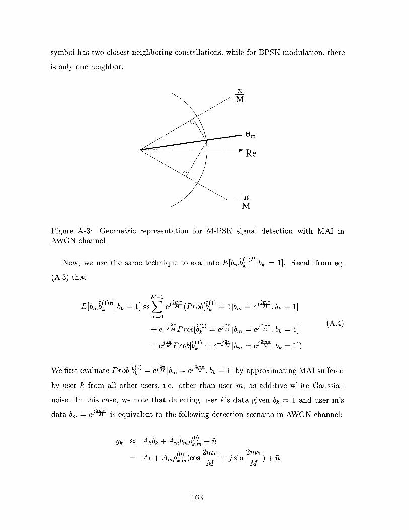
symbol has two closest neighboring constellations, while for BPSK modulation, there
is only one neighbor.
7TM
Om
"Re
Figure A-3: Geometric representation for M-PSK signal detection with MAI inAWGN channel
Now, we use the same technique to evaluate E[bmb 1j)H bk 1]. Recall from eq.
(A.3) that
M-1
E~bb~)Hbkk kE~mlHk 1] ~ M (Pr ob[b ' = 1|bm = M , bk = 1]m=O
j .2M bk 1 (A.4)e-F e Prob[b = eim|br = e -,b=1 ) b =1]
+ e M Prob[b' = e-i |b b , bk = 1]
We first evaluate Prob[b(1 ) = e bm = 0 , bk= 1] by approximating MAI suffered
by user k from all other users, i.e. other than user m, as additive white Gaussian
noise. In this case, we note that detecting user k's data given bk = 1 and user m's
data bn = e m is equivalent to the following detection scenario in AWGN channel:
(0)2m 2mrAk + Amp,)(cos M + j sin M ) + i
163

where ii is a circularly symmetric complex Gaussian random variable with variance
equal to MAIk - A(p ()2 + .2 . The geometric representation for the detection
process is shown in figure A-3. We see that this case differs from single-user detection
in AWGN such that the mean of the phase of y has been tilted by 0 m,k, where
-1 Ampi"(sin0 m,k = tan' AmPks (A.5)
Ak(+ A p ( Cos (Ak m k,m MT
At the same time, the signal-to-noise ratio of y has become
(Ak + Amp os2m7r)2 + (Am0) Sin 2)2(Ymk + Amk,mco COM (APk,m sin 2
MAIk - A2(p) 2 + 02
A~ + A2(p(O) )2 CS2~m+A km + 2AkAmp cos m
M AIk - A2(p) 2 + 6 2
A 2
instead of just I. Using this model and figure A-3, we can apply the same geometric
approximation to evaluate Prob[bW) = eHiibm = e32, bk 1] as in the M-PSK
single-user detection case:
Pr ob[ eAi ibm = eJ 2 , bk = 1] : Q(sin ( M - Om,k '/m,k)
Using similar method, we evaluate the second error probability term in A.4 as
2m~r 7Prob[6b(' = e--il|bm = e ,bk =1] = Q(sin ( + 6 m,k) 7m,k)k M
Therefore, the probability of correct detection, i.e. Prob[W) = llb = e= li, bk =l,
can be approximated as
= Prob[W) = libm = eim7,bk = 1]
.2r~ .2r~ 1 - Psb[ = e bm = H =/1])- Prob[) = - isin MIbm eJ- =b1]
I 1 Q (sin ( r- Om,k) -,fYmk) - Q (sin ( + Om k) mkM M
164

Now we are ready to evaluate E[bmb )'], which can be expressed as
E[bm b1)H] = E[bm(1)Hb_ = 1M -1 1 j m-rr1 ___
e M (Prob[) = IIbm = e V ,bk = 1]m=0
+e-i Prob[ l)H ebm , bk ~1
+eiHProb[bkH _ -lbm A 7 k 11)M-1 j2r
M eM (1 Q(Sin (-Omk)Ym,k) - Q(sin + Om,k) /m,k)m=0
+e- MQ(sin ( - Om,k)V/7m,k) + eL Q(sin (? + Om,k) ,/Ymk))M M
e m(Q(sin -Om,k) V/m,k)e -1)
m=O7I 27r
+Q (sin (- + Orm,k)V'M)e -
where simplification in the first step is due to constellation and conjugate symmetry
and simplification in the last step is due to the fact that EZ =O e = 0.
The accuracy of the approximation is similar to that in M-PSK detection, i.e. the
larger the M and Ak are, the more accurate the approximation. Furthermore, let's
look at the accuracy of the approximation for the case of BPSK, i.e. M = 2. If we
assume that Ak > Amp , which is usually the case in a system with good power
control, we see from the expression in eq. (A.5) that 0 m,k = 0 since sin mr = 0. In
this case, the signal-to-interference ratio becomes:
( k+ (0)Ak+AmPkm
MAIk--A2 (p0 )2+a2
Ymk Ak-Amp()
MAIk-A(p()2+ 2
ifM = 0
if M= 1
In this setting, we find E[bmb l)H] as
E[bmbil)H] (-4Q(Yo,k) + 4Q(71,k))
AQ - Amp"( Ak + Amp)2(Q( k0 -Q 0
MAIk - A2 (p0) )2 + 02 MAIk - A2 (p() )2 + 0.2
165

which is exactly a factor of 2 from the exact correlation value of E[bmb1)H] for BPSK,
which we calculated earlier in this section. This factor of 2 difference is again con-
tributed by the fact that we have considered two closest neighbors in the approxima-
tion rather than one.
Finally, we obtain the expression for the off-diagonal terms in Aal, i.e. Aali(m, k)
for n 0 k, as
A(' (m, k) = E[bm b1)H]M-1
S e (Q(sin ( - Omk) 'Ymk)(e~ -1)M=O M
7_ (e 27r+Q(sin ( 7 + Om,k) Ymk)(e - 1))
The derivation of AI' for synchronous DS-CDMA system using multistage detection
is now complete.
To extend our derivation to the asynchronous case, we first take a look at the
structure of A(') that spans over L symbols, which can be expressed as
A(l)0(1) AM,1(1) 0 ... ... 0
Aa -1) A()-1(2) A(l) 0 (2) A(l) 0 (2) 0 ... 0
0 ... ... 0 A( 1)'(L) A(1)'0(L)
where
A(')'0 (l) = E[b(1)b(l)H (1)
A(')-'1) =E[b(l)b^(1)Hj _)
A('),' ( = E[b(l)b)H(l + 1)]
The zero terms in the matrix is due to the fact that E[b(j)P)H(k) = 0 for I - kI > 1
because for any pair of users, the current symbol of one user does not have an impact
through MAI on the symbol of the other user that is transmitted more than one
166

symbol interval before and after. In other words, each symbol of the desired user are
only going to be affected by two symbols from each of the other users, one in the
current symbol interval, and one either in the immediate past of future depending on
the delay offset.
Our remaining task is to evaluate A(')' 0 (l), A(')' 1 (l) and A(')'1(1). We first look
at A 1)'0 (l) = E[b(l)b(1)H(l)], which is a K-by-K matrix with off-diagonal entries
found using our approximation method as
A(''4(1)m,k =E[bm(l)6(l)H (1)]
e (Q(sin( - 0m,k())J m,k(l))(e - 1)
+Q(sin ( + Om,k(1)) VYm,k (1))(e( - 1)
where m # k and
0m,k (1)Am(l)p~o (l)Sin(27r + Om - Ok)
=tan- ~Ak(l) + Am(l)pk(l) cos ( + Om - kk)
Ak(1) 2 + Am(l)2( ()) 2 + 2Ak(l)Am(l)P (l)cos( k)
MAIk (l) - A2± (1)(p (1))2 + a.2
where
K
MAIk(l)= ((Am (1)p (0)())2
m=1,mAk
+ ( Am(1 - 1)pg5,) (1))2u(Tm - Tk) + (Am(1 + 1)p ())2( T
We next calculate AM''1(l) = E[b(l)b(1)H(l + 1)]. The diagonal entries of this
matrix, i.e. E[bm(l)bW (1 + 1)], are all zero because successive transmitted symbols of
the same user are independent. For off-diagonal terms, we see that E[bm(l)W)((l+ 1)] =
167

0 for all Tm > Tk. For the case where rm Tk, we find that
E[bm(l)b$1 (l + 1)] ej l(Q(sin ( -- 9 m,k (l+ 1)) Vm,k (l + 1)) (e- - 1)M E
+Q(sin ( + dm,k(1 + 1)) 1)m,k(l + )( - 1))
Am(l)p 1)(l + 1) sin (r + O m - Ok)
Ak(l +1) + Am(l~ (1 + 1) COS ( + Om - Ok)
Ak(l + 1)2 + Am l)2 (p(5) (I + 1))2 + 2Ak (l + 1)Am(l)p(j~)(l + 1) cos (' + Om
MAIk (l + 1) - A2 (1 + 1))2 + 0,2
- Ok)
Thus, we can express the entries of A('C1 (1) as
- (Tm - k) ZM=O
e (Q(sin (I - 6m,k (l)) 'm,k (l)(e~ - 1)M
+Q(sin ( 7r + 6m,k (l)) m,k(l))(eM -- 1))
Using similar method, we can find the entries of A('),- 1 (1) as
= E[bm(l) W)(l - 1)]IM--1
U(k -Tm) Em=0
e (Q(sin (( -mk(l- - 1) (e 1
+Q(sin ( + Om,k(l -- 1) -ym,k(l - 1 ed - 1))
where
6m,k(l - 1)
Ym,k
= tan 1Am(l)p() (l - 1) sin ( 2 + m - Ok)
Ak(l -1)+ Am(l)p 1 ) (l -1) COs ( + Om - 'k)
Ak(l - 1)2 + Am(l)2 () (1 _ 1))2 + 2Ak(l -1)Am(l)p( ( - 1) cos( 2 ' + Om - kk)
MAIk(l - 1) - A2(l)(p~) (1 - 1))2 + 0.2
To summarize, we have derived the weighting matrix Aa(1) to be used in multistage
interference cancellation with MMSE-based feedback matrix for K users (each of
168
where
= tan 1dm,k(l + 1)
Ym,k
A C1'l1l0m,k
A('),-'1( )m,k

which transmits L symbols) as
A.(') =
A (' 0 (1)
A W, - 1(2)
0
where
1 - (1 - cos 2 )
n E -j e7 (Q(sin (- - Om,k(l)) ym,k (l))(e - 1)
+Q(sin (R + Om,k (l)) 7mk(l))(ej - 1))
0
if k = m
if k $r m and i
if k $ m and i> 1
M - 1 -j 2 7
u(Tm - Tk)u(2 - i e M (Q(sin ( - m,k (l)) m,k (l))(e~ - 1)m=0 M
+Q (sin (! + Om,k (l) m,k (l))(ej - 1))
= U(rk - rm) U(2 - i) e ' (Q(sin( - #m,k(1)) Ym,k ())(e - 1)
+Q(sin ( + Om,k (l)) Y,k(l))(e - 1))
where u(t) equals 1 if t > 0 and equals 0 otherwise. This completes our derivation
for Aai).
Now we look at the convergence behavior of Aa(i) in a system with random spread-
ing codes, perfect power control and stationary channel (i.e. A1 (1) = A 2 (1) = ... =
AK(L) = A) as K -+ oc and N -+ oo while keeping K- = 3. The expression for
the diagonal terms of Aaul) are clearly unaffected, since they only depend on the
modulation format and the error probability of each user in the previous stage. The
off-diagonal terms, however, are going to vanish, which we show next.
169
A(z)'l (1)
A '0 (2)
0
A()' 0(2) 0
0
0
0 A('),-'(L) A('),O(L)
A(',' m,k =

We first examine the asymptotic behavior of 0 m,k (1). Due to perfect power control,
we have
Ap()sin2_"+0 kOmk(l) = tan- Apm(1) sin( m m
A + Ap (1) cos (2, + Om - 4k)
tn (1) sin ( 2 + Om - $k)(tan-' +km -
+ p (1) Sin( (m7 + m - #)
For random spreading codes, it has been shown in [56] that E[pk0 m(l)] 0 and
E[(p(O (l))2] oc 9!. Therefore, as N -+ oo, p (l) converges to zero in mean-square
sense. This means that Om,k(l) -+ 0 as N -+ oo. Similar arguments can be made
to show that Om,k(l) and Om,k(l) also converge to zero in mean-square sense as the
spreading factor becomes infinitely large.
Next, we look at the asymptotic behavior of Yk,m(l). As K -+ oc, (Amp Po)2 is
going to be negligible compared to MAIk. We therefore can express 'Yk,m(l) as
7k,mn() -+
A 2 (1 + (p (l))2 + 2p 0 (l) cos (' + m - Ok))
MAIk(l) + G.2
A2
MAIk(1) +U 2
where the convergence in the second step is due to the asymptotic behavior of pM(l)
as N -+ o.
Using asymptotic behaviors of Om,k(l) and 7Ym,k, we see that
A(' (I)m,k = E[bm(l)b(j)H(1)1
I M-1m r,,7F A 2
~ ~~e M~sn(j 2~A 7re~ 1~ n e (Q(sin ( ) MAI + 2)(
+(sin.(lr) MA 2 M-1
= Qsin( )Y MAIk + o.2)(e +ei - 2) e
==0
170

Using similar procedure, we can also show that
0
A(),-1) m,k ~ 0
Therefore, in a system with perfect power control and random spreading codes,
as K and N both approach infinity, Aa W can be approximated as
W() 0 0
0 W()
0
0
00 0
0 0 W(M
where W(') is a K-by-K diagonal matrix that can be evaluated depending on modu-
lation format of bk. For a M-PSK modulated system, we found previously that
W() (k, k) ~ 1 - Pei (I - cos 27rk M
171

Appendix B
Proof of Theorem 4.1 and 4.2
In this appendix, we derive theorems 4.1 and 4.2 by finding a lower bound on the
decorrelator SIR for a particular user (w.l.o.g. user 1) in terms of the singular value
of the correlation matrix. We first prove theorem 4.1, assuming linear independence
between the spreading codes of different users.
Following the decorrelator detector model in section 2, we express z, the soft out-
put vector that contains detection statistics for all users from decorrelator detection,
as follows:
z =R+y
SR- 1 (RAd + n)
= Ad + R--n
Since the detection decision for the data bit of user 1 is made as d, = sgn(zi), the
SIR for user 1 with decorrelator detection is
decorr -1 E[j(R-1 n)1 2]
where (R-'n)1 is the first element in vector R-'n. The derivation of the lower bound

then proceeds as follows:
A42pdecorr -
1
1 E[l(R- 1n)1i2]A 2
Fil(I|R-11In), 12]
A 2
max (R--1)NPA oin(R)
Np7 1,sync,ind
where 1|R-'1H is the induced 2-norm of R- [12].
We now show that this lower bound is obtainable for some noise vector n. Suppose
that the singular decomposition of the symmetric matrix R is R = VEVT, the
worst case of noise amplification happens when n = Vk, where Vk is the singular
vector corresponding to the minimum singular value of R (or the singular vector
corresponding to the maximum singular value of R- 1 ). Also note that since R is
symmetric, its singular values equal to the eigen values. Since the noise is white,
any subspace orientation for the vector n is possible. Therefore the lower-bound in
theorem 4.1 is achievable. Hence the proof for theorem 4.1 is complete.
Now we use the same approach to prove theorem 4.2 by assuming that the one-
shot cross-correlation matrix R is singular. In this case, the expression of the output
vector i from decorrelator detection is then:
z = f+f kd+N+n
- -[ 1 o][ E OvT - -t=V 0 VTV VTA+R+n0 0 0 0
=V I 0 VTkA l +n0 0
=M .2+ f+n
173

where V E 0 VT is the singular value decomposition (SVD) of A, with E, being
a L-by-L diagonal matrix containing the L non-zero singular values of f on the
diagonal, where L < 2K - 1. The matrix M has elements
I [ ,1 vi ,2 ... Vi,L-1 Vi,L j,1 Vj, 2 '. Vj,L-1 Vj,L
where vii is the lth element of the ith right singular vector of R. Note that because
V is a 2K - 1-by-2K - 1 orthogonal matrix, Mj is always less than or equal to 1.
Now we can express the SIR of decorrelator in this case as:
~decorr M A
2 M A + E[(-I1n)1|2i[=2 M A± 1'-N
2.A? + Npi=2 1mi (R&min
where the inequality follows from the same reason as in the proof of theorem 4.1. The
lower bound can be achieved by the same manner as in theorem 4.1. The proof for
theorem 4.2 is thus complete.
174

Bibliography
[1] V. Veeravalli and B. Aazhang, "On the Coding-Spreading Tradeoff in CDMA
Systems," Proc. 1996 Conf. Inform. Sci. Syst., Princeton University, Princeton,
NJ, Mar. 1996, p. 1136-1141.
[2] F. Adachi, M. Sawahashi, and H. Suda, "Wideband DS-CDMA for Next Genera-
tion Mobile Communications Systems," IEEE Communications Magazine, Sept.
1998, p. 56-69.
[3] P. Agin and F. Gourgue, "Comparison Between Multicode with Fixed Spreading
and Single Code with Variable Spreading Options in UTRA/TDD," 2nd IEEE
Workshop on Signal Processing Advances in Wireless Communications, 1999. p
325-328.
[4] K. Araki, "Fundamental Problems of Nationwide Mobile Radio-telephone Sys-
tem," NTT Rev. Elec. Comm. Lab., 1968.
[5] D. Ayyagari and A. Ephremides, "Cellular Multicode CDMA Capacity for Inte-
grated (Voice and Data) Services," IEEE Journal on Selected Areas in Commu-
nications, Vol. 17, No. 5, May 1999, p. 928-938.
[6] Z. D. Bai and Y. Q. Yin, "Limit of the smallest eigenvalue of a large dimensional
sample covariance matrix," IEEE Trans. Infor. Theory, 20:284-287, Mar. 1974.
[7] N. Chan, "Multipath Propagation Effects on a CDMA Cellular System," IEEE
Trans. Veh. Technol., vol. 43, Nov., 1994, p. 848-855.
175

[8] A. Chan and G. Wornell, "A Class of Asymptotically Optimum Iterated-
Decision Multiuser Detectors," Proc. Int. Conf. Acost, Speech, Signal Processing
(ICASSP-2001), Salt Lake City, UT, May 2001.
[9] K. Cheun, "Performance of Direct-sequence Spread-spectrum RAKE Receivers
with Random Spreading Sequences," IEEE Trans. Commun., vol. 45, Sept 1997,
p. 1130-1143.
[10] T. Cover and J. Thomas, Elements of Information Theory, John Wiley and Sons,
Inc., 1991.
[11] E. Dahlman and K. Jamal, "Wide-band Services in a DS-CDMA based FPLMTS
System," Proc. Vehic. Tech. Conf.'96, Atlanta, GA, May 1996, p. 1656-1660.
[12] M. Dahleh, M. Dahleh, and G. Verghese, "Lectures on Dynamic Systems and
Control", Dept. of Elec. Eng. and Comp. Sci., Mass. Inst. Tech., 2000.
[13] A. Duel-Hallen, "Decorrelating Decision-feedback Multiuser Detector for Syn-
chronous CDMA," IEEE Trans. Commun., Vol. 41, pp. 285-290, Feb. 1993.
[14] EIA/TIA Interim Standard, "Cellular System Dual Mode Mobile Station - Land
Station Compatibility Specifications," IS-54, Electronic Industries Association,
May 1990.
[15] M. Fan and K.-Y. Siu, "Weighted Multistage Interference Cancellation Based
on Constrained MMSE Optimization," to be submitted to IEEE J. Select. Area.
Comm.
[16] P.Z. Fan, N. Suehiro, N. Kuroyanagi and X. M. Deng, " Class of binary sequences
with zero correlation zone", it IEEE Electronic Letters, vol: 35, issue: 10, May
1999, pp. 777-779.
[17] W. Feller, An Introduction to Probability Theory and Its Applications, vol. 1 &
2, Wiley, New York, 1966.
176

[18] M. Fong, V. K. Bhargava and Q. Wang, "Concatenated Orthogonal/PN Spread-
ing Sequences and Their Application to Cellular DS-CDMA Systems with Inte-
grated Traffic," IEEE Journal on Selected Areas in Communications., Vol. 14,
No. 3, April 1996, p. 547-558.
[19] G.D. Forney, "Modulation and Coding for Linear Gaussian Channels," IEEE
Trans. Infor. Theory, vol. 44, no. 6, October, 1998, pp. 2384-2414.
[20] R. Frenkiel, "A High-capacity Mobile Radio-telephone System," IEEE Trans.
Veh. Tech., 1970.
[21] K. S. Gilhousen, et. al., "On the Capacity of a Cellular CDMA System," IEEE
Trans. Veh. Technol., vol. 40, May 1991, p. 303-311
[22] I. Gradshteyn and I. Ryzhik, Table of Integrals, Series, and Products. Academic
Press, San Diego, CA, 1980.
[23] H. Harashima and H. Miyakawa, "A Method of Code Conversion for A Digital
Communication Channel with Intersymbol Interference," IEEE Trans. Comm.,
vol. COM-20, Aug. 1972, p. 774-780.
[24] M. Honig, U. Madhow and S. Verdu, "Blind Adaptive Multiuser Detection,"
IEEE Trans. Infor. Theory, vol. 41, No. 4, July 1995, p. 944-960.
[25] S. Ramakrishna and J. Holtzman, "A Comparison between Single Code and
Multiple Code Transmission Schemes in a CDMA System", In Proceedings of
VTC'98, pages 791-795, Vol. 2, 1998.
[26] J. Holtzman, "A Simple, Accurate Method to Calculate Spread-spectrum
Multiple-Access Error Probabilities", IEEE Transactions on Communications,
Vol. 40, No. 3, March 1992, p. 461-464.
[27] C-L. I and R. D. Gitlin, "Multi-code CDMA wireless personal communication
networks," ICC'95 Seattle, WA, Vol. 2, Page(s): 1060 -1064, June 1995.
177

[28] C-L. I. and R. D. Gitlin, "Variable Spreading Gain CDMA," AT&T Lab Note-
book, pp. 9-11, August 1993.
[29] W. Jang, B. Vojcic and R. Pickholtz, "Joint Transmitter-Receiver Optimiza-
tion in Synchronous Multiuser Communications over Multipath Channels," IEEE
Trans. Comm., vol. 46, no. 2, Feb. 1998, p. 269-278.
[30] A. Johansson and A. Svensson, "Analysis of Successive Interference Cancellation
Scheme in Multiple Data Rate DS/CDMA Systems," Technical Report No. 15,
Department of Information Theory, Chalmers University of Technology, Gothen-
burg, Sweden, August 1995.
[31] M. Kavehrad and J. Salz, "Cross-polarization Cancellation and Equalization in
Digital Transmission over Dually Polarized Multipath Fading Channels," AT&T
Technical Journal, Vol. 64, pp. 2211-2245, Dec. 1985.
[32] Kiran and D. N. C. Tse, " Effective Interference and Effective Bandwidth of Lin-
ear Multiuser Receivers in Asynchronous CDMA Systems," IEEE Trans. Inform.
Theory, vol. 46, July, 2000, p. 1426-1447.
[33] A. Klein, G. Kaleh, and P. Baier, "Zero-Forcing and Minimum Mean-Square-
Error Equalization for Multiuser Detection in Code-Division Multiple-Access
Channels," IEEE Trans. Vehicular Technology, Vol. 45, No. 2, May 1996, p.
276-287.
[34] E. L. Kuan, L. Hanzo, "Joint Detection CDMA Techniques for Third-Generation
Transceivers," Proc. ACTC Mobile Communications Summit, Rhodes, Greece,
June 1998, pp. 727-732.
[35] K. C. Hwang and K. B. Lee, "Performance analysis of low processing gain
DS/CDMA systems with random spreading sequences," IEEE Commun. Lett.,
Vol. 2, No. 12, pp. 315-317, Dec. 1998.
[36] E. Lee and D.G. Messerschmitt, Digital Communication, second edition, Kluwer
Academic Publishers, ISBN 0-7923-9391-0.
178

[37] W. C. Lee, "Overview of Cellular CDMA," IEEE Trans. Vehicular Technology,
Vol. 40, No. 2, May 1991, p. 291-302.
[38] W. Lee, Mobile Communications Engineering: Theory and Applications, 2nd ed.,
New York: McGraw-Hill, 1998.
[39] S. J. Lee, H. W. Lee, and D. K. Sung, "Capacities of Single-code and Multicode
DS-CDMA Systems Accommodating Multiclass Services," IEEE Trans. Vehic.
Tech., Vol. 48, No. 2, March 1999, p. 376-384.
[40] R. K. Morrow and J. S. Lehnert, "Bit-to-bit Error Dependence in Slotted
DS/SSMA Pakcet Systems with Random Signature Sequences," IEEE Trans
Commun., Vol. COM-37, pp. 1052-1061, Oct. 1989.
[41] W. C. Y. Lee, "The most spectrum-efficient duplexing system: CDD," IEEE
Commun. Magazine, vol. 40, no. 3, Mar. 2000, pp. 163-166.
[42] U. Madhow and M. L. Honig, "MMSE Interference Suppression for Direct-
Sequence Spread-Spectrum CDMA," IEEE Trans. Comm., Vol. 42, December
1994, p. 3178-3188.
[43] P. Shamain and L. Milstein, "Using Higher Order Constellations with Minimum
Mean Square Error (MMSE) Receiver for Severe Multipath CDMA Channel,"
Personal, Indoor and Mobile Radio Communications, 1998. The Ninth IEEE
International Symposium on, Vol. 3, 1998, p. 1035-1039.
[44] T. Minn and K.-Y. Siu, "Variable Chip Rate CDMA," Proc. VTC2000, May
2000, p. 2267-2271.
[45] T. Minn and K. Y. Siu, "Dynamic assignment of orthogonal variable spreading
factor codes in W-CDMA," IEEE J. Selected Areas Commun.,, vol. 18, pp. 1429-
1440, Aug 2000. Special Issue in Wideband CDMA.
[46] S. Moshavi, "Multi-user Detection for DS-CDMA Communications," IEEE Com-
munications Magazine, Oct. 1996, p. 124-136.
179

[47] M. Mouly and M. Pautet, The GSM System for Mobile Communication, ISBN:
2-9507190-0-7, 1992.
[48] T. Ojanpera, R. Prasad, Wideband CDMA for Third Generation Mobile Com-
munications, London: Arctech House, 1998.
[49] T. Ottoson and A. Svensson, "Multi-Rate Schemes in DS/CDMA Systems,"
Proc. IEEE Vehic. Tech. Conf., Chicago, IL, July 25-28, 1995, p. 1006-1010.
[50] T. Ottosson and A. Svensson, "Multi-Rate Performance in DS/CDMA Systems,"
Technical Report No. 14, Dept. of Information Theory, Chalmers University of
Technology, Goteborg, Sweden, 1995.
[51] P. Patel and J. Holtzman, "Analysis of a simple successive interference cancel-
lation scheme in DS/CDMA system," IEEE J. Select Areas Commun., vol. 12,
pp. 796-807, June 1994.
[52] R. Pickholtz, D. Schilling and L. Milstein, "Theory of Spread-spectrum
Communications-A Tutorial," IEEE Transactions on Communications, Vol.
COM-30, No. 5, May 1982, p. 855-884.
[53] "Performance of Multirate Techniques in DS-CDMA Systems",
http://perth.mit.edu/.
[54] H. V. Poor and S. Verdu, "Probability of Error in MMSE Multiuser Detection,"
IEEE Trans. Information Theory, Vol. 43, No. 3, May 1997, p. 858-871.
[55] J. G. Proakis, Digital Communications, 3rd ed., New York: McGraw-Hill, 1995.
[56] D. V. Sarwate, M. B. Pursley, "Partial Correlation Effects in Direct-Sequence
Spread-Spectrum Multiple-Access Communication Systems," IEEE. Trans.
Comm., Vol. Com-32, May, 1984, p. 567-573.
[57] M. B. Pursley, "Performance Evaluation for Phase-coded Spread-spectrum
Multiple-access Communication - Part I: System Analysis," IEEE Trans.
Comm., Vol. COM-25, pp. 795-799, Aug. 1977.
180

[58] T. Rappaport, Wireless Communications: Principles and Practice. Upper Saddle
River, N.J.: Prentice Hall, 1996.
[59] R.A. Scholtz, "The origins of spread-spectrum communications," IEEE Trans.
Commun., Vol. COM-30, No. 5, May 1982, pp. 822-854.
[60] N. Seidl, I. Howitt and J. Richie, "Blind Adaptive Linear Multiuser Detection
for Multirate CDMA Systems," Proc. VTC 2000, Sept. 2000, p. 1296-1303.
[61] B. Zhu, N. Ansari and Z. Siveski, "Convergence and stability analysis of a syn-
chronous adaptive CDMA receiver" IEEE Trans. Commun., Vol. 43, pp. 3073-
3079, Dec. 1995.
[62] D. Divsalar, M. Simon and D. Raphaeli, "Improved Parallel Interference Can-
cellation for CDMA," IEEE Trans. Commun., Vol. 46, No. 2, pp. 258-268, Feb.
1998.
[63] G. Strang, Linear Algebra, Wellesley, MA: Wellesley-Cambridge Press, 1993.
[64] N. Suehiro, "A signal design without co-channel interference for approximately
synchronized CDMA systems," IEEE Journ. Select. Area. Comm., vol. 12, no.
5, 1994, pp. 837-841.
[65] TIA/EIA Interim Standard-95, "Mobile station - base station compatibility stan-
dard for dual-mode wideband spread spectrum cellular system," July 1993.
[66] CATT, "TD-SCDMA Radio Transmission Technology for IMT-2000 candidate
submission", Proposal to ITU for G3 RTT, September, 1998.
[67] D. N. C. Tse and S. V. Hanly, "Linear multiuser receivers: Effective interference,
effective bandwidth and user capacity," IEEE Trans. Inform. Theory, vol. 45,
Mar, 1999, p. 641-657.
[68] Y. Chang, D. Tse and D. G. Messerschmitt, "Multimedia CDMA Wireless Net-
work Design: the Link Layer Perspective," VTC'96.
181

[69] G. Turin, "Introduction to Spread-Spectrum Antimultipath Techniques and
Their Applications to Urban Digital Radio," Proceedings of the IEEE, Vol. 68,
No. 3, March 1980, p. 328-353.
[703 M. K. Varanasi and B. Aazhang, "Multistage Detection in Asynchronous Code-
division Multiple Access Communications," IEEE Trans. Commun., Vol. 38, pp.
509-519, Apr. 1990.
[71] M. Varanasi, "Group Detection for Synchronous Gaussian Code-division Multi-
ple Access Channels," IEEE Trans. Infor. Theory, vol. 41, No. 4, July 1995, p.
1083-1096.
[72] V. V. Veeravalli, "The Role of Coding in CDMA Systems with Multiuser Detec-
tion," 1997 IEEE International Conference on Personal Wireless Communica-
tions, p. 470-474.
[73] S. Vembu and A. J. Viterbi, "Two Different Philosophies in CDMA - A Com-
parison," IEEE Vehicular Technology Conference, 1996, Vol. 2, p. 869-873.
[74] S. Verdu, "Minimum Probability of Error For Asynchronous Gaussian Multiple
Access Channels," IEEE Trans. Information Theory, Vol. IT-32, No.1, Jan. 1986,
p. 85-96.
[75] S. Verdu, Multiuser Detection, New York: Cambridge University Press, 1998.
[76] S. Verdu and S. Shamai, "Spectral Efficiency of CDMA with Random Spreading,"
IEEE Trans. Information Theory, Vol. 45, No. 2, Mar. 1999, p. 622-639.
[77] P. Viswanath, V. Anantharam, D. Tse, "Optimal Sequences, Power Control, and
User Capacity of Synchronous CDMA Systems with Linear MMSE Multiuser
Receivers," IEEE Trans. Infor. Theory, vol. 45, no. 6, Sept, 1999, p. 1968-1983.
[78] A. J. Viterbi, CDMA: Principles of Spread Spectrum Communications, Reading,
Massachusetts: Addison-Wesley Publishing Company, 1995.
182

[79] B. Vojcic and W. Jang, "Transmitter Precoding in Synchronous Multiuser Com-
munications," IEEE Trans. Comm., vol. 46, no. 10, Oct. 1998, p. 1346-1355.
[80] T. Wada, T. Yamazato, M. Katayama, and A. Ogawa, "A Constant Amplitude
Coding for Orthogonal Multi-code CDMA Systems," IEICE Trans. Fundamen-
tals, Vol. E80-A, No. 12, December 1997, p. 2477-2483.
[81] N. Correal, R. Buehrer and B. Woerner, "A DSP-based DS-CDMA Multiuser
Receiver Employing Partial Interference Cancellation," IEEE J. Select. Areas
Commun., Vol. 17, No. 4, pp. 613-630, April, 1999.
[82] T. Wong and T. Lok, "Transmitter Adaptation in Multicode DS-CDMA Sys-
tems," IEEE JSAC, vol. 19, No. 1, Jan. 2001, p. 69-82.
[83] G. Wu, A. Jalali and P. Mermelstein, "On Channel Model Parameters for Mi-
crocellular CDMA Systems," IEEE Trans. Veh. Technol., vol. 44, No. 3, August
1995, p. 706-711.
[84] Z. Xie, R. T. Short, and C. K. Rushforth, "A Family of Suboptimum Detectors
for Coherent Multi-User Detectors," IEEE JSAC, Vol. 8, No. 4, May 1990, pp.
683-90.
[85] K. Yao, "Error Probability of Asynchronous Spread Spectrum Multiple Access
Communication Systems," IEEE Trans Commun., vol. COM-25, pp. 802-809,
Aug. 1977.
[86] Y. C. Yoon, R. Kohno, and H. Imai, "Cascaded Co-channel Interference
Cancelling and Diversity Combining for Spread-spectrum Multi-access Over
Multipath Fading Channels," Symp. Information Theory and its Applications
(SITA '92), Minakami, Japan, Sept., 1992.
[87] Young, W.R., "Advanced Mobile Phone Service: Introduction, Background, and
Objectives," Bell Systems Technical Journal, Vol. 58, pp. 1-14, January 1979.
183

[88] R. Zhang, T. Tihung, H. Zhang and P. He, "BER Performance Comparison of
Single Code and Multicode DS/CDMA Channelization Schemes for High Rate
Data Transmission," IEEE Commun. Letters, vol. 5, No. 2, Feb. 2001, p. 67-69.
184