interference suppression pcx2 339 film capacitors (mini ... · interference suppression pcx2 339...
TRANSCRIPT

Pilkor components
Interference Suppression PCX2 339film capacitors (Mini_Fecuma)
TYPE SPECIFICATION 1 OF 21
08-03-20 ( C ) PILKOR ELECTRONICS 2008 QSN-075-51
MKP RADIAL POTTED CAPACITORS Pitch 10.0/15.0/22.5/27.5mm
QUICK REFERENCE DATA
Capacitance range (E6 series) * Capacitance tolerance Rated (AC) voltage 50 to 60 Hz Climatic category Maximum application Temperature Reference IEC specification Safety approvals
Potting & Encapsulation material Safety class
0.001㎌ to 3.3㎌ ± 10 %, ± 20 % 305 V~
55/110/21 110℃ IEC 60384-14(3rd edition) and EN 60384-14 UL1414 & CSA-C 22.2 NO. 1 UL1283 & CSA-C 22.2 NO. 8 ENEC, CQC Qualified in accordance with UL 94V-0 X2
* Intermediate values of the E12 series are available to special order
FEATURES
. 10.0 to 27.5 mm lead pitch
. Supplied loose in box and taped on reel . Consist of a low-inductive wound
cell of Metallized Polypropylene film, potted in a flame retardant case
APPLICATIONS
. For X2-electromagnetic interference suppression
. Specially designed to meet the NEW REQUIREMENTS in new IEC 60384-14 specification( 2005)/EN 132400 requiring for X2 a 2.5kV peak pulse voltage test and the UL1414 and CSA-C22.2 No 1 specification
• Please refer to caution and warning at http://www.pilkor.co.kr/download/Introductions.pdf before using these products.
10 and 15mm 22.5 and 27.5mm

Pilkor components
Interference Suppression PCX2 339film capacitors (Mini_Fecuma)
TYPE SPECIFICATION 2 OF 22
08-03-20 ( C ) PILKOR ELECTRONICS 2008 QSN-075-51
Ordering Information
Code Packing method Lead configuration C - tol 12NC 0 Loose in box lt = 5.0 ± 1.0mm C-tol ±20 % PCX2 339xx0xxx 1 Loose in box lt = 5.0 ± 1.0mm C-tol ±10 % PCX2 339xx1xxx 4 Loose in box lt = 25 ± 2.0mm C-tol ±20 % PCX2 339xx4xxx 5 Loose in box lt = 25 ± 2.0mm C-tol ±10 % PCX2 339xx5xxx 2 Taped on reel H = 18.5 mm* / P0=12.7mm C-tol ± 20% PCX2 339xx2xxx 3 Taped on reel H = 18.5 mm* / P0=12.7mm C-tol ± 10% PCX2 339xx3xxx 6 Ammopack H = 18.5 mm* / P0=12.7mm C-tol ± 20% PCX2 339xx6xxx 7 Ammopack H = 18.5 mm* / P0=12.7mm C-tol ± 10% PCX2 339xx7xxx C Loose in box lt = 3.2 ±0.3mm C-tol ± 20% PCX2 339xxCxxxD Loose in box lt = 3.2 ±0.3mm C-tol ± 10% PCX2 339xxDxxx
* H ; intape height ; for detailed specifications refer to chapter PACKAGING
Capacitance
PCX2 339 X X XXX
Code Pitch D 10.0 mm F 15.0 mm J 22.5 mm L 27.5 mm
X
Code Voltage
6 305V (Fecuma wire)

Pilkor components
Interference Suppression PCX2 339film capacitors (Mini_Fecuma)
TYPE SPECIFICATION 3 OF 21
08-03-20 ( C ) PILKOR ELECTRONICS 2008 QSN-075-51
SAFETY APPROVALS SAFETY APPROVALS Voltage Value File Number
UL1283 & CSA-C22.2 No. 8 (cUL) 305V(AC) 1nF to 3.3㎌ E208404
UL1414 & CSA-C22.2 No. 1 (cUL) 250V(AC) 1nF to 1.0㎌ E165646
ENEC(SEMKO) * 305V(AC) 1nF to 3.3㎌ SE/0256-4
CQC 305V(AC) 1nF to 3.3㎌ IN-PROCESS * The ENEC-approval together with the CB-Certificate replace all national approval marks of the following countries(they have already signed the ENEC-Agreement): Austria; Belgium; Czech. Republic; Denmark; Finland; France; Germany; Greece; Hungary; Ireland; Italy; Luxembourg; Netherlands; Norway; Portugal; Slovenian; Spain; Sweden; Switzerland and United Kingdom
Packaging Information
SMALLEST PACKING QUANTITIES (SPQ) LOOSE IN BOX
DIMENSIONS lt = 3.2 ± 0.3 mm lt = 5.0 ± 1.0 mm lt = 25 ± 2.0 mm
4.0 x 10.0 x 12.5 2000 1200 5.0 x 11.0 x 12.5 1500 1000 6.0 x 12.0 x 12.5 1000 1000
5.0 x 11.0 x 18.0 1000 1000 6.0 x 12.0 x 18.0 1000 1000 7.0 x 13.5 x 18.0 1000 1000
8.5 x 15.0 x 18.0 1000 1000
10.0 x 16.5 x 18.0 1000 1000 11.0 x 18.5 x 18.0 1000 1000
6.0 x 15.5 x 26.0 1000 1000 7.0 x 16.5 x 26.0 1000 1000 8.5 x 18.0 x 26.0 500 500
10.0 x 19.5 x 26.0 500 500 11.5 x 21.0 x 26.0 500 500 13.0 x 23.0 x 26.0 500 500 9.0 x 18.0 x 31.0 500 500
11.0 x 21.0 x 31.0 500 250
13.0 x 23.0 x 31.0 250 250 15.0 x 25.0 x 31.0 250 250 18.0 x 28.0 x 31.0 200 200

Pilkor components
Interference Suppression PCX2 339film capacitors (Mini_Fecuma)
TYPE SPECIFICATION 4 OF 21
08-03-20 ( C ) PILKOR ELECTRONICS 2008 QSN-075-51
SPECIFIC REFERENCE DATA FOR 305 VAC
Tangent of loss angle at 1 khz at 10 khz
C ≤ 470 ㎋ 470 ㎋ < C ≤ 1 ㎌
C > 1 ㎌
≤ 10 x 10 -4 ≤ 20 x 10 -4 ≤ 30 x 10 –4
≤ 20 x 10 -4 ≤ 70 x 10 -4
-
Rated voltage pulse slope (dV/dt)R 100 V/㎲ R between leads, for C ≤ 0.33 ㎌ 〉15 000 ㏁
RC between leads, for C > 0.33 ㎌ 〉5 000 s
Test voltage (DC) on line; C ≤ 1 ㎌
C > 1 ㎌
2250 V 1850 V
VRac = 305 V~ X2 loose and taped
CATALOGUE NUMBER PCX2 339 ..... loose in box
lt = 5 ± 1.0 mm lt = 25 ± 2.0 mm
Cap. (㎌)
b x h x l (mm)
MASS(g)
C – tol. ±20 %
C – tol. ±10 %
C – tol. ±20 %
C – tol. ±10 %
Pitch = 10.0 ± 0.4 mm dt = 0.6 +0.06/-0.05 mm 0.001 4.0x 10.0x 12.5 0.8 D60102 D61102 D64102 D65102 0.0015 4.0x 10.0x 12.5 0.8 D60152 D61152 D64152 D65152 0.0022 4.0x 10.0x 12.5 0.8 D60222 D61222 D64222 D65222 0.0033 4.0x 10.0x 12.5 0.8 D60332 D61332 D64332 D65332 0.0047 4.0x 10.0x 12.5 0.8 D60472 D61472 D64472 D65472 0.0068 4.0x 10.0x 12.5 0.8 D60682 D61682 D64682 D65682 0.01 4.0x 10.0x 12.5 0.8 D60103 D61103 D64103 D65103 0.015 4.0x 10.0x 12.5 0.8 D60153 D61153 D64153 D65153 0.022 4.0x 10.0x 12.5 0.8 D60223 D61223 D64223 D65223 0.033 5.0x 11.0 x 12.5 0.9 D60333 D61333 D64333 D65333 0.047 5.0x 11.0 x 12.5 0.9 D60473 D61473 D64473 D65473 0.068 6.0 x 12.0 x 12.5 1.0 D60683 D61683 D64683 D65683 0.1 6.0 x 12.0 x 12.5 1.0 D60104 D61104 D64104 D65104

Pilkor components
Interference Suppression PCX2 339film capacitors (Mini_Fecuma)
TYPE SPECIFICATION 5 OF 21
08-03-20 ( C ) PILKOR ELECTRONICS 2008 QSN-075-51
VRac = 305 V~ X2 loose and taped
CATALOGUE NUMBER PCX2 339 ..... loose in box
lt = 5 ± 1.0 mm lt = 25 ± 2.0 mm Cap. (㎌)
b x h x l (mm)
MASS(g)
C – tol. ±20 %
C – tol. ±10 %
C – tol. ±20 %
C – tol. ±10 %
Pitch = 15.0 ± 0.4 mm dt = 0.6 +0.06/-0.05 mm
0.01 5.0 x 11.0 x 18.0 0.8 F60103 F61103 F64103 F65103 0.015 5.0 x 11.0 x 18.0 0.8 F60153 F61153 F64153 F65153 0.022 5.0 x 11.0 x 18.0 0.8 F60223 F61223 F64223 F65223 0.033 5.0 x 11.0 x 18.0 0.9 F60333 F61333 F64333 F65333 0.047 5.0 x 11.0 x 18.0 0.9 F60473 F61473 F64473 F65473 0.068 5.0 x 11.0 x 18.0 1.6 F60683 F61683 F64683 F65683 0.1 5.0 x 11.0 x 18.0 1.6 F60104 F61104 F64104 F65104
0.15 6.0 x 12.0 x 18.0 1.7 F60154 F61154 F64154 F65154 Pitch = 15.0 ± 0.4 mm dt = 0.8 +0.08/-0.05 mm
0.22 7.0 x 13.5 x 18.0 1.9 F60224 F61224 F64224 F65224 0.33 8.5 x 15.0 x 18.0 2.6 F60334 F61334 F64334 F65334 0.47 10.0 x 16.5 x 18.0 3.1 F60474 F61474 F64474 F65474
0.68 11.0 x 18.5 x 18.0 4.1 F60684 F61684 F64684 F65684 Pitch = 22.5 ± 0.4 mm dt = 0.8 +0.08/-0.05 mm
0.22 6.0 x 15.5 x 26.0 3.0 J60224 J61224 J64224 J65224 0.33 6.0 x 15.5 x 26.0 3.0 J60334 J61334 J64334 J65334 0.47 7.0 x 16.5 x 26.0 3.5 J60474 J61474 J64474 J65474 0.68 8.5 x 18.0 x 26.0 4.4 J60684 J61684 J64684 J65684 1.0 10.0 x 19.5 x 26.0 5.5 J60105 - J64105 -
1.0 11.5 x 21.0 x 26.0 6.5 - J61105 - J65105
1.5 13.0 x 23.0 x 26.0 8.0 J60155 J61155 J64155 J65155 Pitch = 27.5 ± 0.4 mm dt = 0.8 +0.08/-0.05 mm
0.68 9.0 x 19.0 x 31.0 5.5 L60684 L61684 L64684 L65684 1.0 11.0 x 21.0 x 31.0 7.8 L60105 L61105 L64105 L65105 1.5 13.0 x 23.0 x 31.0 10.4 L60155 L61155 L64155 L65155 2.2 15.0 x 25.0 x 31.0 12.8 L60225 L61225 L64225 L65225 3.3 18.0 x 28.0 x 31.0 17.2 L60335 L61335 L64335 L65335
Pilkor components
Interference Suppression PCX2 339film capacitors (Mini_Fecuma)
TYPE SPECIFICATION 6 OF 21
08-03-20 ( C ) PILKOR ELECTRONICS 2008 QSN-075-51
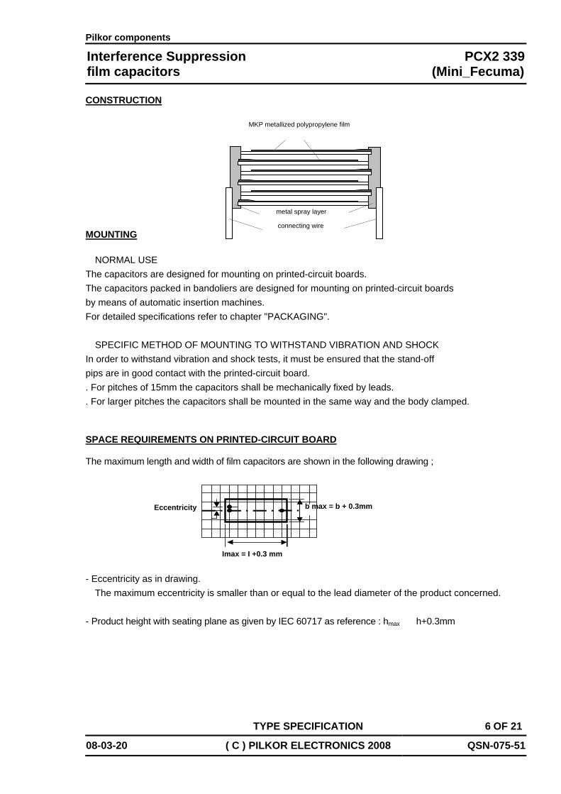
CONSTRUCTION MOUNTING
NORMAL USE
The capacitors are designed for mounting on printed-circuit boards. The capacitors packed in bandoliers are designed for mounting on printed-circuit boards by means of automatic insertion machines. For detailed specifications refer to chapter "PACKAGING".
SPECIFIC METHOD OF MOUNTING TO WITHSTAND VIBRATION AND SHOCK
In order to withstand vibration and shock tests, it must be ensured that the stand-off pips are in good contact with the printed-circuit board. . For pitches of 15mm the capacitors shall be mechanically fixed by leads. . For larger pitches the capacitors shall be mounted in the same way and the body clamped.
SPACE REQUIREMENTS ON PRINTED-CIRCUIT BOARD
The maximum length and width of film capacitors are shown in the following drawing ;
- Eccentricity as in drawing. The maximum eccentricity is smaller than or equal to the lead diameter of the product concerned.
- Product height with seating plane as given by IEC 60717 as reference : hmax ≤ h+0.3mm
MKP metallized polypropylene film
metal spray layer
connecting wire
Eccentricity
Imax = I +0.3 mm
b max = b + 0.3mm

Pilkor components
Interference Suppression PCX2 339film capacitors (Mini_Fecuma)
TYPE SPECIFICATION 7 OF 21
08-03-20 ( C ) PILKOR ELECTRONICS 2008 QSN-075-51
RATINGS AND CHARACTERISTICS
Unless otherwise specified all electrical values apply to an ambient temperature of 23±1℃, an atmospheric pressure of 86 to 106kPa and a relative humidity 50±2%.
For reference testing, a conditioning period shall be applied of 96±4 hours by heating the products in a circulating air oven at the rated temperature and a relative humidity not exceeding 20%. Maximum RMS Voltage as a function of frequency
103
102
101
101 102 103 105104
AC voltage (V)
f(Hz)
AC voltage (RMS value) as a function of frequency at Tamb≤110℃

Pilkor components
Interference Suppression PCX2 339film capacitors (Mini_Fecuma)
TYPE SPECIFICATION 8 OF 21
08-03-20 ( C ) PILKOR ELECTRONICS 2008 QSN-075-51
PRODUCT MARKING Capacitors are marked with having following information; 1.Manufacturer (PILKOR) 2.Manufacturer's type designation (PCX2 339 ) 3.Rated capacitance in code according to IEC 60062 4.Rated (AC) voltage (305V~) 5.Sub class (X2) 6.Tolerance on rated capacitance M =±20 % K = ±10 % 7.Climatic category (55/110/21) 8.Code for dielectric material (MKP) 9.Year and week of manufacturing (e.g. 0810) 10.Safety approvals Example of marking Pitch P = 7.5mm or 10mm
Marking on the side Pitch P = 15mm or 22.5mm
Marking on the top Marking on the side Pitch P = 22.5mm or
Marking on the top Marking on the top Marking on the side Pitch P = 27.5 mm.
Marking on the top DATA ON LABEL
For 4E/6E/9E/11E
1 Manufacturer’s name 2 Sub-family 3 Type description and safety class X2 4 Capacitance value, tolerance, voltage and climatic category (IEC) 5 Safety approvals 6 Batch nr. & production period year
and week code 7 Quantity and Product code (12NC)
*** Color of label : Pink
Color of Safety Marking : Red
100n K 305V~ X2 PCX2 339 MKP
PILKOR 0810
55/110/21
680n M 305V~ X2 PCX2 339 MKP PILKOR 0810 55/110/21
680n M 305V~ X2PCX2 339 MKP PILKOR 0810 55/110/21
X2
10n M 305V~ 339 PILKOR 0810
0810 55/110/21
PILKOR Electronics INTERF. SUPPR. FILM CAPACITOR MKP RADIAL POTTED TYPE X2 0.1uF ±20% 305V~ 55/110/21
2000 PCX2 339F60104
DATE 0112BATCH NO 126137
Safet
EN132400
Pilkor components
Interference Suppression PCX2 339film capacitors (Mini_Fecuma)
TYPE SPECIFICATION 9 OF 21
08-03-20 ( C ) PILKOR ELECTRONICS 2008 QSN-075-51
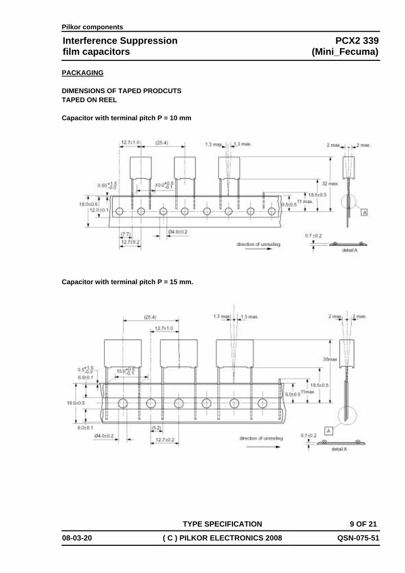
PACKAGING DIMENSIONS OF TAPED PRODCUTS TAPED ON REEL Capacitor with terminal pitch P = 10 mm
Capacitor with terminal pitch P = 15 mm.

Pilkor components
Interference Suppression PCX2 339film capacitors (Mini_Fecuma)
TYPE SPECIFICATION 10 OF 21
08-03-20 ( C ) PILKOR ELECTRONICS 2008 QSN-075-51
Capacitor with terminal pitch P = 22.5 or 27.5 mm
ITEM SYMBOL VALUE VALUE TOLERANCELEAD TO LEAD DISTANCE(mm) F 22.5 27.5 +0.5/-0.1 HEIGHT OF COMPONENT FROM TAPE CENTER TO SEATING PLANE(mm) H 18.5 0.5
COMPONENT HEIGHT FROM TAPE CENTER(mm) H1 40 max 48 max
FEED HOLE TO LEAD CENTER(mm) P1 7.8 5.33 0.7

Pilkor components
Interference Suppression PCX2 339film capacitors (Mini_Fecuma)
TYPE SPECIFICATION 11 OF 21
08-03-20 ( C ) PILKOR ELECTRONICS 2008 QSN-075-51
CHARACTERRISTICS OF TAPED PRODCUTS Cumulative pitch error 1.0mm/20 pitches Pull-out force of the component ≥ 5 N Pull-out force of the adhesive tape ≥ 6 N Tearing force of tape ≥ 15 N Storage temperature - 25 to + 40 ℃ Relative humidity max. 80% without condensation The max. number of empty places per reel shall not exceed 0.5% of the total number of components per reel, but no more than 2 consecutive positions may be vacant. Outlines of reel & ammo packing (dimensions in mm)
W as function of product dimensions
l = 12.5 or 18.0 mm l = 26 or 31 mm
b (mm) W 2 (mm) b (mm) W 2 (mm)
4.0 5.0 6.0 7.0 8.5 10.0
40 45 45 45 45 50
6.0 7.0 8.5 9.0
10.0 11.0 13.0 15.0 18.0
50 50 50
50 50 55 55 60 60

Pilkor components
Interference Suppression PCX2 339film capacitors (Mini_Fecuma)
TYPE SPECIFICATION 12 OF 21
08-03-20 ( C ) PILKOR ELECTRONICS 2008 QSN-075-51
INSPECTION REQUIREMENTS Note 1 : Sub-clause numbers of tests and performance requirements refer to the Sectional Specification, IEC 384-14 and Section One this specification. Note 2 : Inspection levels are selected from IEC-Publication 410: Sampling Plans and Procedures for inspection by attributes. Note 3 : In this table : p = periodicity in months n = sample size D = destructive ND = non-destructive IL = inspection level ) IEC 410 AQL = acceptance quality level ) Note 4 : For this capacitors, considered as a solid construction, the periodicity of the vibration and shock test is reduced from 36 months to 6 months.
Clause number and Test
D or ND
Condition IL n Performance Requirements
Group A inspection (lot by lot)
Sub-Group A1 ND
4.1 Visual examination Detail S4 1) No visual damage , legible marking and as specified in Marking specification
4.1 Dimensions 2) S3 1) As specified in dimension table of this specification
Sub-Group A2 3) ND
4.2.2 capacitance At 1kHz Within specified tolerance
4.2.3 Tangent of loss angle At 10kHz C ≤ 1㎌ At 1kHz C > 1㎌
As in rating and characteristics of this specification
4.2.4 Voltage proof (test A)
1. C ≤ 1㎌ 2250V 1min
2. C > 1㎌ 1850V 1min
No permanent breakdown (cut-off current 10mA) or flash over Self-healing allowed
4.2.5 Insulation resistance (test A)
At 100V As in rating and characteristics of this specification
1) Number to be tested : Sample size as directly allotted to the code letter for IL in Table 2A of IEC 410 (Single sampling plan for normal inspection) The acceptance number complies with AQL value : 0.65 % 2) This test may be replaced by in-production testing, if SPC on dimensional measurements or
other mechanisms to avoid parts exceeding the limits is installed. 3) The 100% End-of-line testing is followed by re-inspection by sampling in order to monitor outgoing quality level by defectives per million (DPM). The sampling level and the calculation of DPM values is in accordance with CECC 00 014, counting any parametric failure as a defective. In case one or more defectives occur in a lot, this lot
shall be rejected.

Pilkor components
Interference Suppression PCX2 339film capacitors (Mini_Fecuma)
TYPE SPECIFICATION 13 OF 21
08-03-20 ( C ) PILKOR ELECTRONICS 2008 QSN-075-51
Clause number and Test
D or ND
Condition p n Performance Requirements
Group C inspection (periodic)
6 6
Sub-group C1A Part of a sample of sub-group C1
D
4.1 dimension (detail) As specified in dimension table of this specification
4.3.1 initial measurement 1. Capacitance at 1kHz 2. Tangent of loss angle at 10kHz C ≤ 1㎌ at 1kHz C > 1㎌
4.3 robustness of terminations Tensile and bending No visible damage
4.4 resistance to soldering heat Method : 1A Solder bath : 260℃ Duration : 10 s
4.14 component solvent resistance
Isopropylalcohol at room temperature Method : 2 Immersion time : 5±0.5min Recovery time: min 1hour max 2hours
Visual examination No visible damage Legible marking
1. Capacitance at 1kHz Δ C/C ≤ 5% of the value measured initially
2. Tangent of loss angle at 10kHz C ≤ 1㎌ at 1kHz C > 1㎌
Increase of tanD For C ≤ 1㎌
< 0.0080 For C > 1㎌ < 0.0050
4.4.2 final measurements
Insulation resistance As in rating and characteristics of this specification

Pilkor components
Interference Suppression PCX2 339film capacitors (Mini_Fecuma)
TYPE SPECIFICATION 14 OF 21
08-03-20 ( C ) PILKOR ELECTRONICS 2008 QSN-075-51
Clause number and Test
D or ND
Condition p n Performance Requirements
Group C inspection (periodic)
Sub-group C1B Other part of a sample of sub-group C1
D
6
12
4.6.1 initial measurement
1. Capacitance at 1kHz 2. Tangent of loss angle at 10kHz C ≤ 1㎌
at 1kHz C > 1㎌
4.6 rapid change of temperature Θ A = lower category temperature Θ B = upper category temperature 5 cycles duration time : 30 min
4.7 vibration (see note 4)
Method of mounting : see the mounting of this specification Procedure : B4 Frequency range
10Hz to 55Hz amplitude : 0.75mm or acceleration 98m/s2(which is less severe) Total duration : 6 hours
4.7.2 final examination Visual examination
No visible damage
4.9 shock (see note 4) Method of mounting : see the mounting of this specification Pulse shape : half sine Acceleration : 490 m/s2 Duration of pulse : 11ms
Visual examination No visible damage
1. Capacitance at 1kHz Δ C/C ≤ 5% of the value measured initially
2. Tangent of loss angle at 10kHz C ≤ 1㎌ at 1kHz C > 1㎌
Increase of tanD For C ≤ 1㎌
< 0.0080 For C > 1㎌ < 0.0050
4.9.3 final measurements
Insulation resistance As in rating and characteristics of this specification

Pilkor components
Interference Suppression PCX2 339film capacitors (Mini_Fecuma)
TYPE SPECIFICATION 15 OF 21
08-03-20 ( C ) PILKOR ELECTRONICS 2008 QSN-075-51
Clause number and Test
D or ND
Condition p n Performance Requirements
Group C inspection (periodic)
Sub-group C1 Combined sample of specimens of sub-groups C1A and C1B
D
6
18
4.11 climatic sequence
4.11.2 dry heat T = Tupper-category temperature Duration : 16 hours
4.11.3 damp heat cyclic test Db, first cycle
4.11.4 cold T = Tlower-category temperature Duration : 2 hours
4.11.6 damp heat cyclic test Db, remaining cycle
Visual examination No visible damage Legible marking
1. Capacitance at 1kHz Δ C/C ≤ 5% of the value measured initially
2. Tangent of loss angle at 10kHz C ≤ 1㎌ at 1kHz C > 1㎌
Increase of tanD For C ≤ 1㎌
< 0.0080 For C > 1㎌ < 0.0050
4.11.6.2 final measurements
Insulation resistance ≥ 50% of values in ratings and characteristics of this specification
Pilkor components
Interference Suppression PCX2 339film capacitors (Mini_Fecuma)
TYPE SPECIFICATION 16 OF 21
08-03-20 ( C ) PILKOR ELECTRONICS 2008 QSN-075-51
Clause number and Test
D or ND
Condition p n Performance Requirements
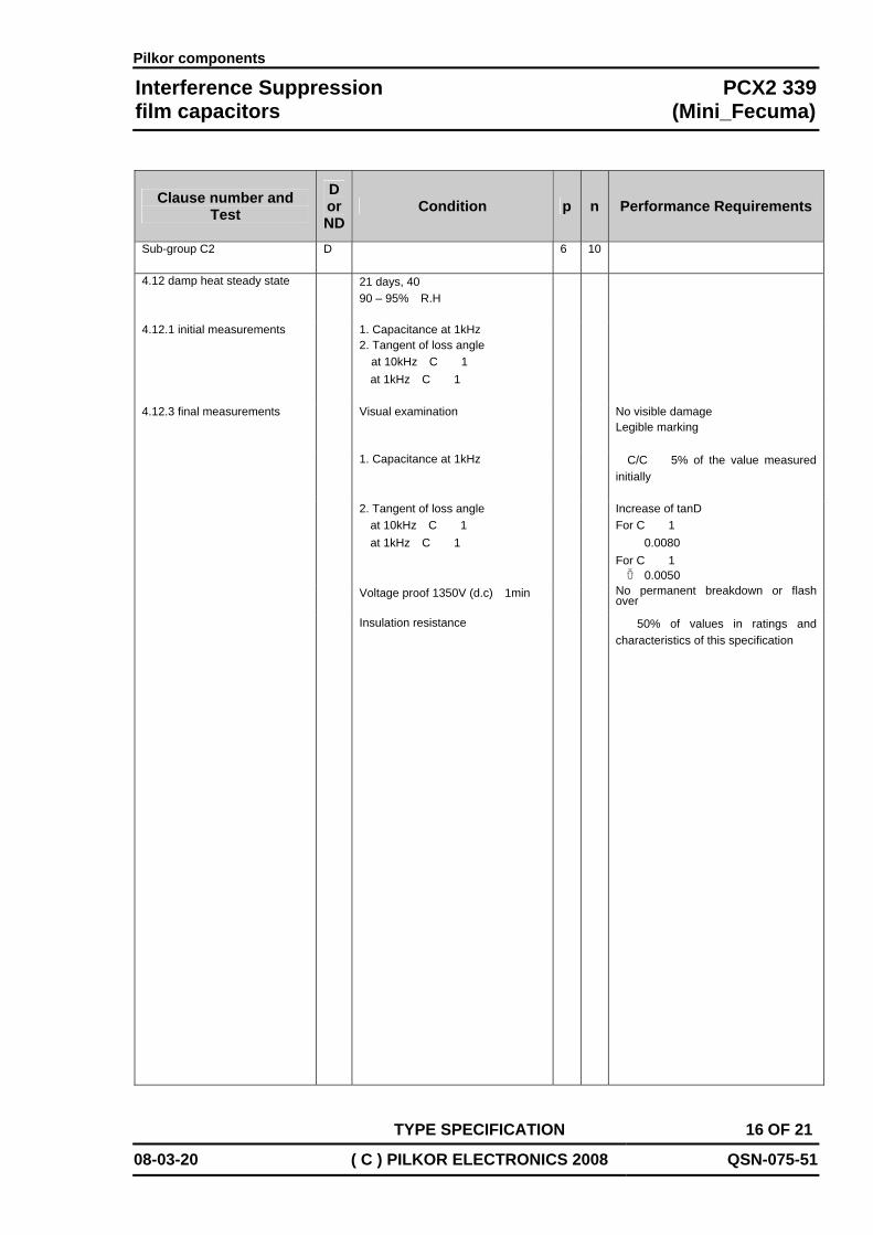
Sub-group C2
D 6 10
4.12 damp heat steady state 21 days, 40℃ 90 – 95% R.H
4.12.1 initial measurements 1. Capacitance at 1kHz 2. Tangent of loss angle at 10kHz C ≤ 1㎌
at 1kHz C > 1㎌
Visual examination No visible damage Legible marking
1. Capacitance at 1kHz Δ C/C ≤ 5% of the value measured initially
2. Tangent of loss angle at 10kHz C ≤ 1㎌ at 1kHz C > 1㎌
Increase of tanD For C ≤ 1㎌
< 0.0080 For C > 1㎌ < 0.0050
Voltage proof 1350V (d.c) 1min No permanent breakdown or flash over
4.12.3 final measurements
Insulation resistance ≥ 50% of values in ratings and characteristics of this specification

Pilkor components
Interference Suppression PCX2 339film capacitors (Mini_Fecuma)
TYPE SPECIFICATION 17 OF 21
08-03-20 ( C ) PILKOR ELECTRONICS 2008 QSN-075-51
Clause number and Test
D or ND
Condition p n Performance Requirements
Sub-group C3
D 3 12
4.13.1 initial measurements 1. Capacitance at 1kHz 2. Tangent of loss angle at 10kHz C ≤ 1㎌
at 1kHz C > 1㎌
4.13 peak impulse voltage 3 successive impulse, full wave, peak voltage :
for C ≤ 1㎌ : 2.5kV for C > 1㎌ : 2.5kV/√ C ( C in ㎌)
max : 24 pulses
No selfhealing breakdown or flashover
4.14 endurance test Duration : 1000 hours 1.25 x URac at 110℃ once in every hour the voltage is increased to 1000V(RMS) for 0.1 s via a resistor of 47Ω ± 5%
Visual examination No visible damage Legible marking
1. Capacitance at 1kHz Δ C/C ≤ 10% of the value measured initially
2. Tangent of loss angle at 10kHz C ≤ 1㎌ at 1kHz C > 1㎌
Increase of tanD For C ≤ 1㎌
< 0.0080 For C > 1㎌ < 0.0050
Insulation resistance ≥ 50% of values in ratings and characteristics of this specification
4.12.3 final measurements
Voltage proof 1350V (DC) for 1 min No permanent breakdown or flashover

Pilkor components
Interference Suppression PCX2 339film capacitors (Mini_Fecuma)
TYPE SPECIFICATION 18 OF 21
08-03-20 ( C ) PILKOR ELECTRONICS 2008 QSN-075-51
Clause number and Test
D or ND
Condition p n Performance Requirements
Sub-group C4
D 6 6
4.15.1 initial measurements 1. Capacitance at 1kHz 2. Tangent of loss angle at 10kHz C ≤ 1㎌
at 1kHz C > 1㎌
4.15 charge and discharge 10000 cycles : charge to UR half sine wave Duration : 5ms Discharge resistance with a minimum : 2.2Ω
1. Capacitance at 1kHz Δ C/C ≤ 10% of the value measured initially
2. Tangent of loss angle at 10kHz C ≤ 1㎌ at 1kHz C > 1㎌
Increase of tanD For C ≤ 1㎌
< 0.0080 For C > 1㎌ < 0.0050
4.15.3 final measurements
Insulation resistance ≥ 50% of values in ratings and characteristics of this specification
R = URAC x √2
1.5 x C x (dU/dt)

Pilkor components
Interference Suppression PCX2 339film capacitors (Mini_Fecuma)
TYPE SPECIFICATION 19 OF 21
08-03-20 ( C ) PILKOR ELECTRONICS 2008 QSN-075-51
Clause number and Test
D or ND
Condition p n Performance Requirements
Sub-group C6
D 12 18
4.17 passive flammability
Bore of gas jet : φ 0.5 mm Fuel : Butane Test duration for actual volume V in mm3
class C
Volume(mm3) Gas jet
V ≤ 250 5s 250〈 V ≤ 500 10s 500〈 V ≤ 1750 20s
V >1750 30s One flame application
1.class C After removing test flame from capacitor, the capacitor must not continue burn for more than 30 s. 2.No burning particle must drop from the sample
Sub-group C7
D 12 24
4.18 active flammability 20 discharges of a 3 uF tankcapacitor across the test capacitor. The test capacitor during the discharges connected to UR (16A). UR is maintained for 2 min after the last discharge
The cheese cloth around the capacitor shall not burn with a flame. Not electrical measurements are required.
45O
612

Pilkor components
Interference Suppression PCX2 339film capacitors (Mini_Fecuma)
TYPE SPECIFICATION 20 OF 21
08-03-20 ( C ) PILKOR ELECTRONICS 2008 QSN-075-51
Clause number and Test
D or ND
Condition p n Performance Requirements
Sub-group ADD1
D 3 10
A.1 Solder ability Without aging Method : 1 Non-activated colophiny flux 501 Solder bath : 235℃ Dwell time : 2 s
Good tinning as evidenced by free flowing of the solder with wetting of the termination(>95%)
Solvent resistance of the marking
Isopropylalcohol at room temperature. Method : 1 Rubbing material cotton wool Immersion time : 5±0.5min
Legible marking
Sub-group ADD2 D 3 12
A.2 Heat storage Duration : 1000h Temperature : upper category temperature
1. Capacitance at 1kHz A.2.1 Initial measurement
2. Tangent of loss angle at 10kHz C ≤ 1㎌
at 1kHz C > 1㎌
1. Capacitance at 1kHz Δ C/C ≤ 5% of the value measured initially
2. Tangent of loss angle at 10kHz C ≤ 1㎌ at 1kHz C > 1㎌
Increase of tanD For C ≤ 1㎌
< 0.0080 For C > 1㎌ < 0.0050
A.2.2 Final measurement
Insulation resistance As in Rating and CHARACTERISTICS of this specification

Pilkor components
Interference Suppression PCX2 339film capacitors (Mini_Fecuma)
TYPE SPECIFICATION 21 OF 21
08-03-20 ( C ) PILKOR ELECTRONICS 2008 QSN-075-51
Clause number and Test
D or ND
Condition p n Performance Requirements
Sub-group ADD3
D 3 9
A.3 Detergent resistance Density 20g/L dishwasher detergergent Temperature 70℃ during 3 minutes followed by rinsing in clear water for 1 minute Recovery time : 1 to 2 hours
Good tinning as evidenced by free flowing of the solder with wetting of the termination(>95%)
1. Capacitance at 1kHz A3.1 Initial measurement
2. Tangent of loss angle at 10kHz C ≤ 1㎌
at 1kHz C > 1㎌
1. Capacitance at 1kHz Δ C/C ≤ 5% of the value measured initially
2. Tangent of loss angle at 10kHz C ≤ 1㎌ at 1kHz C > 1㎌
Increase of tanD For C ≤ 1㎌
< 0.0080 For C > 1㎌ < 0.0050
A.3.2 Final measurement
Insulation resistance ≥ 50% of values in ratings and characteristics of this specification
Sub-group ADD4 D 6 10
A.4 Resistance to soldering heat with preheating
Capacitors mounted on 1.6mm board with nonplated hole Body temp : 100℃ Bath temp : >260 Dwell time : 10 s
1. Capacitance at 1kHz A.2.1 Initial measurement
2. Tangent of loss angle at 10kHz C ≤ 1㎌ at 1kHz C > 1㎌
1. Capacitance at 1kHz Δ C/C ≤ 5% of the value measured initially
A.2.2 Final measurement
`
Increase of tanD For C ≤ 1㎌
< 0.0080 For C > 1㎌ < 0.0050