interface converter g.703.1 64 kbit/sec - cronyx micro · interface converter ... the pcm64 is...
TRANSCRIPT

1.1E / 08.11.2005Copyright © 1999-2005 Cronyx
1234567890123456789012345678901212345678901234567890123456789012123456789012345678901234567890121234567890112345678901234567890123456789012123456789012345678901234567890121234567890123456789012345678901212345678901
Interface converter
G.703.1 64 kbit/sec
Features
• Maximum line attenuation -10 dB
• G.703 line interface 64 kbit/sec
• Duplex mode
• V.35/RS-530/RS-449/RS-232
digital interface
• Capability to double the data trans-
mission rate
• Digital, local and remote loops
• Built-in Bit Error Rate tester (BER
tester);
• Two DTE emulation modes
• Alarm interface (“dry” relay con-
tacts)
• Built-in mains or battery power sup-
ply unit
Contents
Purpose
Technical specifications
Delivered items
Order code
Controls and indicatorsFront panel controls
Front panel indicators
DIP switches
Synchronization modesCommon synchronization
Separate synchronization
LoopsNormal operation
Digital loop
Remote loop
Local loop
Remote loop selection
Emergency alarms
Rear panel connectors
Cable diagrams
PCM64 converter
User’s Guide

PCM64
interface converter123456789012345678901234567890121234567890123456789012345678901212345678901234567890123456789012123456789012345678901234567890121234567890123456123456789012345678901234567890121234567890123456789012345678901212345678901234567890123456789012123456789012345678901234567890121234567890123456
Copyright © 1999-2005 Cronyx 2
Functions
The PCM64 is designed for converting G.703.1 64 kbit/sec interface signals into
synchronous and asynchronous interfaces of terminal data transmission equipment (DTE).
The device is manufactured in two models – a universal one, having codirectional and
contradirectional G.703 interface operating modes, and a model having only a codirectional
G703 interface. The converter may be used to create a duplex data transmission link
using digital trunking equipment. The converter allows connecting computers, routers,
terminals, etc. to digital trunking equipment with a codirectional 64 kbit/s interface
(G.703.1). The presence of a built-in synchronous/asynchronous converter provides
the capability to connect to asynchronous ports of various equipment. The built-in BER
tester and the capability to enable a loop remotely on the remote device allow testing link
from the local device completely. The capability to enable external receiver and transmitter
clocks allows selecting one of the two DTE port emulation modes when connecting the
converter to a DCE device. The PCM64 converter allows operating at double transmission
rate (128 kbit/sec) in the line.
Technical specifications
Digital interface
Data transmission rate Async 115, 57.6, 38.4, 19.2, 9.6, 4.8,
2.4, 1.2, 0.6 and less kbit/sec;
Sync 64 or 128 kbit/sec
Clock signals TXC, RXC, ETC, ERC
Modem signals DSR, CTS, RTS, CD
G.703 interface (64 kbit/sec)
Connector removable terminal
Encoding G.703.1
Line impedance 120 Ohms (balanced twisted pairs)
Signal level at the receiver input 0 to -10 dB
Transmitter path synchronization INT (from the internal clock)
RCV (from the receiver path)
EXT (from the digital interface)
Alarm interface
Connector Mini-DIN 6-pin female
Relay contact current up to 250 mA
Relay contact voltage up to 175 VDC

PCM64
interface converter12345678901234567890123456789012123456789012345678901234567890121234567890123456789012345678901212345678901234567890123456789012123456789012345671234567890123456789012345678901212345678901234567890123456789012123456789012345678901234567890121234567890123456789012345678901212345678901234567
Copyright © 1999-2005 Cronyx 3
Diagnostic modes
Loops Digital (on the digital
interface)
Local (on the G.703 line at
the local device)
Remote (on the G.703 line at
the remote device)
BER tester Enabled by a button on the front
panel
Delivered items
Delivered items include:
• PCM64 converter of the corresponding design
• Removable terminal for connecting to the line
• Power cable (for models with AC power supply)
• User’s guide
Order code
PCM64C/B-232-AC
Model:PCM64 – codirectionalG.703 jointPCM64C – contradirectionaland codirectional G.703 joint
Power supply:(for desktop design)
AC - ~220VDC - =60V
Digital interface:232 - RS-232530 - RS-530V35 - V.35
Design:B – desktop R – rack

PCM64
interface converter123456789012345678901234567890121234567890123456789012345678901212345678901234567890123456789012123456789012345678901234567890121234567890123456123456789012345678901234567890121234567890123456789012345678901212345678901234567890123456789012123456789012345678901234567890121234567890123456
Copyright © 1999-2005 Cronyx 4
Controls and indicators
Front panel controls
PWR CD RTS RL DL ERR TST TEST MODE
CRONYX PCM64
1. The MODE button enables diagnostic loops. When the button is pressed, the
following loops are enabled in sequence:
Digital loop
Remote loop
Local loop
Normal operation
DL indicator lights
RL indicator lights
RL indicator flashes
DL and RL indicators do not light
Normal operation
The TST button enables the BER tester. When the TST button is pressed again, the
BER tester is disabled. If the BER tester is enabled, the TST indicator lights. In this case
test data are transmitted into the line, and the data received from the line are compared to
the transmitted data, and the ERR indicator lights in case of discrepancy.
Indicators
1. The PWR lights when the device is connected to the power supply.

PCM64
interface converter12345678901234567890123456789012123456789012345678901234567890121234567890123456789012345678901212345678901234567890123456789012123456789012345671234567890123456789012345678901212345678901234567890123456789012123456789012345678901234567890121234567890123456789012345678901212345678901234567
Copyright © 1999-2005 Cronyx 5
2. The CD indicator lights during normal signal level at the receiver input.
The CD signal is set to the active state when the digital loop is enabled, irrespectively
of the signal at the receiver input.
3. The RTS indicator indicates the status of the RTS signal from the DTE connected
to the digital interface.
4. The RL indicator flashes if the local loop is enabled, and lights continuously,
if the remote loop is enabled:
5. The DL indicator lights if the digital loop is enabled.
6. The TST indicator lights if the BER tester is enabled.
7. ERR indicator warns about errors:
ERR indicator Additional Error
conditions cause
Lights CD does not light, No signal at the
codirectional mode G.703 receiver input (loss
of carrier)
Lights CD does not light, No receiver clock
contradirectional (RSYNC) at the
mode interface G.703 input
Lights/flashes DL, TST indicators ERC clock frequency
do not light (normal deviates from the frequency
operating mode) of clocks received from the
ERC mode enabled G.703 line due to loss of
common synchronization
Lights/flashes TST indicator lights Data transmitted by the BER
(BER tester enabled) tester into the line, do not
correspond to the data
received from theline
Flashes EXT synchronization mode 1. Frequency deviation
selected (from the digital of TXCount pulses from the
interface) digital interface
The DL indicator is beyond the permitted
flashes continuously limits, or clock is absent.
2. No cable connected to the
DTE.
3. DTE configured incorrectly.
Flashed Contradirectional No transmitter clock
mode (TSYNC) at the G.703 interface
The DL indicator input
flashes continuously

PCM64
interface converter123456789012345678901234567890121234567890123456789012345678901212345678901234567890123456789012123456789012345678901234567890121234567890123456123456789012345678901234567890121234567890123456789012345678901212345678901234567890123456789012123456789012345678901234567890121234567890123456
Copyright © 1999-2005 Cronyx 6
DIP switches
ON
1 2 3 4 5 6 10987
Sync CTS
RLoopEN
CharLength Mode&BaudRate
Sync - transmitter path synchronization mode
S1:S2 Sync
INT synchronization from the internal clock
RCV synchronization from the G.703 receiver
EXT synchronization from the digital interface
CONTR contradirectional G.703 interface mode
CTS - CTS signal generation logic
S3:S4 CTS
CTS = 1
CTS = RTS
CTS = CD
CTS = CD * RTS
RLoopEn - loop enabling at the remote device request permitted
S5 RLoopEn
prohibited
permitted
CharLength/ERC - Symbol length in the asynchronous mode / External receiver clock
mode in the synchronous mode
S6 CharLength/ERC
9 bit / External ERC clock permitted
8 bit / External ERC clock prohibited

PCM64
interface converter12345678901234567890123456789012123456789012345678901234567890121234567890123456789012345678901212345678901234567890123456789012123456789012345671234567890123456789012345678901212345678901234567890123456789012123456789012345678901234567890121234567890123456789012345678901212345678901234567
Copyright © 1999-2005 Cronyx 7
Mode & Baud Rate - Data transmission rate and mode
S7:S10 BaudRate & Mode
Async 600 bit/sec and less
Async 1200 bit/sec
Async 2400 bit/sec
Async 4800 bit/sec
Async 9600 bit/sec
Async 19200 bit/sec
Async 38400 bit/sec
Async 57600 bit/sec
Async 115200 bit/sec
Sync 64 kbit/sec
Sync 128 kbit/sec
Sync 128 kbit/sec
Sync 128 kbit/sec
Sync 128 kbit/sec
Sync 128 kbit/sec
Sync 128 kbit/sec

PCM64
interface converter123456789012345678901234567890121234567890123456789012345678901212345678901234567890123456789012123456789012345678901234567890121234567890123456123456789012345678901234567890121234567890123456789012345678901212345678901234567890123456789012123456789012345678901234567890121234567890123456
Copyright © 1999-2005 Cronyx 8
Synchronization settings
Setting alternatives with a common clock source
Converter A
TXC
RXC
ETC
DTE A DTE BCLK
Converter B
ETC
RXC
TXC
RCVINT
Common clock from converter A
TXC
RXC
ETC
DTE A DTE B
CLK
ETC
TXC
RXC
EXT RCV
Converter A Converter B
Common clock from DTE À

PCM64
interface converter12345678901234567890123456789012123456789012345678901234567890121234567890123456789012345678901212345678901234567890123456789012123456789012345671234567890123456789012345678901212345678901234567890123456789012123456789012345678901234567890121234567890123456789012345678901212345678901234567
Copyright © 1999-2005 Cronyx 9
Setting alternatives with separate clock sources
Converter A
TXC
RXC
ETC
DTE A DTE B
Converter B
ETC
TXC
RXC
CLK
CLK
EXT INT
Separate clocks from DTE A and converter B
TXC
RXC
ETCCLK
DTE A
ETCCLK
RXC
TXCDTE B
EXT EXT
Converter A Converter B
Separate clocks from DTE À and DTE Â

PCM64
interface converter123456789012345678901234567890121234567890123456789012345678901212345678901234567890123456789012123456789012345678901234567890121234567890123456123456789012345678901234567890121234567890123456789012345678901212345678901234567890123456789012123456789012345678901234567890121234567890123456
Copyright © 1999-2005 Cronyx 10
Converter A
TXC
RXC
ETC
DTE A DTE BCLK
Converter B
CLK
ETC
TXC
RXC
INT INT
Separate clocks from converters À and B
Loops
Normal mode
RXD
RTS
DTE A DTE B
RTS
CD
DSR
TXD
DSR
CD
CTS
TXD
RXD
CTS
Carrier OK
"ON"
Carrier OK
"ON"
Normal mode Normal mode
S3, S4 S3, S4
Converter A Converter B
PCM64
interface converter12345678901234567890123456789012123456789012345678901234567890121234567890123456789012345678901212345678901234567890123456789012123456789012345671234567890123456789012345678901212345678901234567890123456789012123456789012345678901234567890121234567890123456789012345678901212345678901234567
Copyright © 1999-2005 Cronyx 11
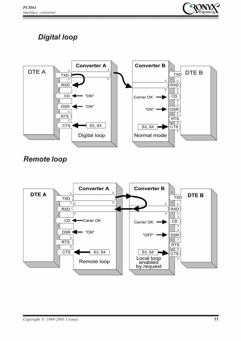
Digital loop
Converter A Converter B
RXD
RTS
DTE A DTE B
RTS
CD
DSR
TXD
DSR
CD
CTS
TXD
RXD
CTS
"ON"
Carrier OK
"ON"
Digital loop Normal mode
"ON"
S3, S4 S3, S4
Remote loop
RXD
RTS
DTE A DTE B
RTS
CD
DSR
TXD
DSR
CD
CTS
TXD
RXD
CTS
"ON"
Carrier OK
"OFF"
Carier OK
S3, S4 S3, S4
Converter A Converter B
Remote loopLocal loopenabled
by request

PCM64
interface converter123456789012345678901234567890121234567890123456789012345678901212345678901234567890123456789012123456789012345678901234567890121234567890123456123456789012345678901234567890121234567890123456789012345678901212345678901234567890123456789012123456789012345678901234567890121234567890123456
Copyright © 1999-2005 Cronyx 12
Local loop
Converter A Converter В
RXD
RTS
DTE A DTE B
RTS
CD
DSR
TXD
DSR
CD
CTS
TXD
RXD
CTS
"OFF"
Carrier OK
"ON"
Local loop Normal mode
Carier OK
S3, S4 S3, S4

PCM64
interface converter12345678901234567890123456789012123456789012345678901234567890121234567890123456789012345678901212345678901234567890123456789012123456789012345671234567890123456789012345678901212345678901234567890123456789012123456789012345678901234567890121234567890123456789012345678901212345678901234567
Copyright © 1999-2005 Cronyx 13
DTE emulation
Two clock inputs - reception and transmission (ERC and ETC) are provided for
connecting PCM64 converter over the digital interface (V.35, RS-530, or RS-232) to
DCE devices in the synchronous mode.
DTE1 emulation mode
The DTE1 emulation mode is used when connecting to DCE devices, which have the
external synchronization from the digital port (RS-232, V.35, RS-530) mode. In this
case a pair of devices connected over the digital port (RS-232, V.35, RS-530) translates
the clock frequency from one line into the other.
Converter A Converter В DCE DTE
TXD
TXC
TXD
RXD
TXD RXD
RXC ETC
RXD
ETC RXC
ETC
DTE1 emulation mode using external receiver clock
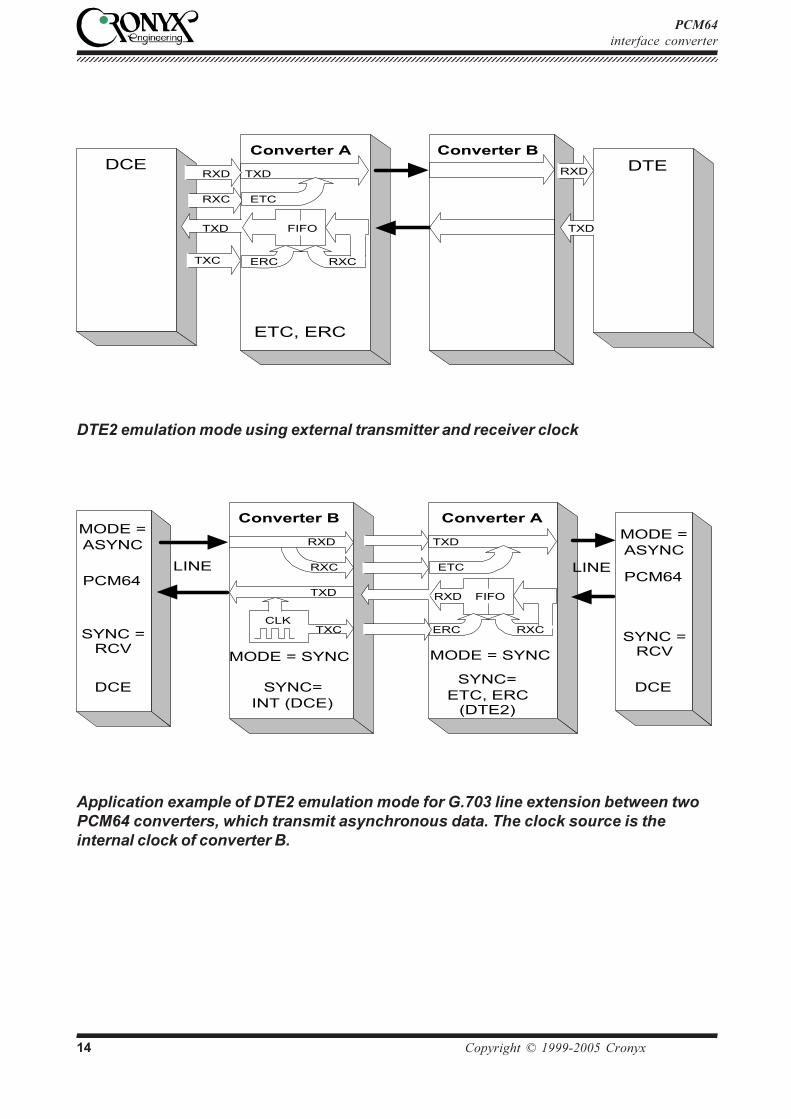
DTE2 emulation mode
The DTE2 emulation mode is used when connecting to DCE devices, which do not
have external synchronization from the digital port (RS-232, V.35, RS-530) mode. In
this case the PCM64 converter receives data to the digital port according to the clock
received on the ETC input, and transmits according to the clock received on the ERC
input. The FIFO buffer is used to correct data phase at the RXD digital port output in
relation to ERC clock. For the correct operation of the buffer (no overflows and
underflows) the clock frequency received from the line must be the same as the frequency
at the ERC input. This condition is maintained when the data transmission link has a
common clock source. Otherwise there may be periodic errors related to FIFO buffer
overflows and underflows. The frequency of these errors depends on the discrepancy
value between these two frequencies.
PCM64
interface converter123456789012345678901234567890121234567890123456789012345678901212345678901234567890123456789012123456789012345678901234567890121234567890123456123456789012345678901234567890121234567890123456789012345678901212345678901234567890123456789012123456789012345678901234567890121234567890123456
Copyright © 1999-2005 Cronyx 14
Converter A Converter B DCE DTE
TXD
TXC
TXD
RXD
TXD RXD
RXC ETC
RXD
ETC, ERC
ERC RXC
FIFO
DTE2 emulation mode using external transmitter and receiver clock
TXD
ETC
SYNC=ETC, ERC
(DTE2)
RXC
FIFO
ERC
RXD
MODE =ASYNC
MODE =ASYNC
MODE = SYNC
TXD
RXC
RXD
SYNC=INT (DCE)
MODE = SYNC
CLKTXCSYNC =
RCVSYNC =
RCV
LINE LINE
DCEDCE
PCM64 PCM64
Converter B Converter A
Application example of DTE2 emulation mode for G.703 line extension between two
PCM64 converters, which transmit asynchronous data. The clock source is the
internal clock of converter B.

PCM64
interface converter12345678901234567890123456789012123456789012345678901234567890121234567890123456789012345678901212345678901234567890123456789012123456789012345671234567890123456789012345678901212345678901234567890123456789012123456789012345678901234567890121234567890123456789012345678901212345678901234567
Copyright © 1999-2005 Cronyx 15
Remote loop selection
In complex configurations, when several PCM64 modems are connected in a sequence,
the DIP switch S5 may be used to specify a LAN section to be checked in the remote loop
mode.
G.703DTE
S5 OFF
DTEDigital
ServiceNetwork
PCM64Local
PCM64 PCM64 PCM64G.703
S5 ON
RL lights - remote RL flashes - local loop
loop mode enables at request
PCM64DTE
S5 ON
DTEDigitalService
Network
PCM64Local
PCM64 PCM64
S5 OFF
RL lights - remote RL flashes - local loop
loop mode enabled at request
Emergency alarms
The emergency alarm interface is used for turning on en external executive unit (ringer,
buzzer, console indicator, etc.) during emergency – loss of bearer, power failure, and
other errors indicated by the “ERR” LED on the front panel. This is enabled by “dry” (not
connected to any electrical circuit of the device) relay contacts.
In the normal state contact 3 is connected to contact 1. In the emergency state contact 3
disconnects from contact 1 and connects to contact 2 (the “alarm” state).

PCM64
interface converter123456789012345678901234567890121234567890123456789012345678901212345678901234567890123456789012123456789012345678901234567890121234567890123456123456789012345678901234567890121234567890123456789012345678901212345678901234567890123456789012123456789012345678901234567890121234567890123456
Copyright © 1999-2005 Cronyx 16
Rear panel connectorsPCM64 model
Fuse
Digital interface
(M34 or DB25 connector)
Alarm
interface
Power supply
220 VAC
XMT-a,b
GND
RCV-b,a
Terminal for connecting
to G.703 line
6
4
21
3
5
Contact
1 Connected to contact (3) during normal operation. Disconnects during
error
2 Disconnected during normal operations.Connected to contact (3)
during error.
3 Middle contact
PCM64C model
Fuse
Digital interface
(M34 or HDB44 connector)
Alarm interface
Power supply
220 VACDB15 connector for connecting
to a G.703 line

PCM64
interface converter12345678901234567890123456789012123456789012345678901234567890121234567890123456789012345678901212345678901234567890123456789012123456789012345671234567890123456789012345678901212345678901234567890123456789012123456789012345678901234567890121234567890123456789012345678901212345678901234567
Copyright © 1999-2005 Cronyx 17
DB15 connector pinout diagram for the G.703.1 interface
of model PCM64C
DB15 pin Signal Direction1 XMT - a Transmit9 XMT - b Transmit3 RCV - a Receive11 RCV - b Receive5 TSYNC - a Receive13 TSYNC - b Receive7 RSYNC - a Receive15 RSYNC - b Receive
2 GND
10 GND
DB25 connector pinout diagram for RS-232 and RS-530
interfaces
Cont. DB25 RS-530 RS-232 Direction.2 TXD-a TXD Receive14 TXD-b — Receive3 RXD-a RXD Transmit16 RXD-b — Transmit24 ETC-a ETC Receive11 ETC-b — Receive21 ERC-a ERC Receive18 ERC-b — Receive15 TXC-a TXC Transmit12 TXC-b — Transmit17 RXC-a RXC Transmit9 RXC-b — Transmit4 RTS-a RTS Receive19 RTS-b — Receive20 DTR-a DTR Receive23 DTR-b — Receive6 DSR-a DSR Transmit22 DSR-b — Transmit5 CTS-a CTS Transmit13 CTS-b — Transmit8 CD-a CD Transmit10 CD-b — Transmit1,7 GND GND —

PCM64
interface converter123456789012345678901234567890121234567890123456789012345678901212345678901234567890123456789012123456789012345678901234567890121234567890123456123456789012345678901234567890121234567890123456789012345678901212345678901234567890123456789012123456789012345678901234567890121234567890123456
Copyright © 1999-2005 Cronyx 18
M34 connector pinout diagram for the V.35 interface
Contact Signal DirectionP TD-a ReceiveS TD-b ReceiveR RD-a TransmitT RD-b TransmitU ET-a ReceiveW ET-b ReceiveBB ERC-a ReceiveZ ERC-b ReceiveY TC-a TransmitAA TC-b TransmitV RC-a TransmitX RC-b TransmitC RTS ReceiveH DTR ReceiveE DSR TransmitD CTS TransmitF DCD TransmitA CGND —B SGND —

PCM64
interface converter12345678901234567890123456789012123456789012345678901234567890121234567890123456789012345678901212345678901234567890123456789012123456789012345671234567890123456789012345678901212345678901234567890123456789012123456789012345678901234567890121234567890123456789012345678901212345678901234567
Copyright © 1999-2005 Cronyx 19
Cable diagrams
V.35 cable for connecting to the DCE using external
transmitter clock
(DTE1 emulation mode)
PCM64 M34 (male) DCE M34 (male)TXD-a P R RXD-aTXD-b S T RXD-bRXD-a R P TXD-aRXD-b T S TXD-bETC-a U V RXC-aETC-b W X RXC-bRXC-a V U ETC-aRXC-b X W ETC-bTXC-a Y Not connectedTXC-b AA Not connectedERC-a BB Not connectedERC-b Z Not connectedRTS C F CDDTR H E DSRDSR E H DTRCD F C RTSGND A A GND
GND B B GND

123456789012345678901234567890121234567890123456789012345678901212345678901234567890123456789012123456789012123456789012345678901234567890121234567890123456789012345678901212345678901234567890123456789012123456789012
V.35 cable for connecting to the DCE using external
receiver and transmitter clocks
(DTE2 emulation mode)
PCM64 M34 (male) DCE M34 (male)TXD-a P R RXD-aTXD-b S T RXD-bRXD-a R P TXD-aRXD-b T S TXD-bETC-a U V RXC-aETC-b W X RXC-bRXC-a V Not connectedRXC-b X Not connectedTXC-a Y Not connectedTXC-b AA Not connectedERC-a BB Y TXC-aERC-b Z AA TXC-bRTS C F CDDTR H E DSRDSR E H DTRCD F C RTSGND A A GND
GND B B GND
Web: www.cronyx.ru E-mail: [email protected]