interesting and useful features of the deltav pid controller · 3-5 ft 3-5 lt 3-2 lc 3-2 rsp column...
TRANSCRIPT

Interesting and UsefulFeatures of the DeltaV PID Controller
James Beall – Emerson Process Management
Introduction
Provide additional information on useful features of the DeltaV PID and related function blocks.
Discuss some common PID function block parameters where the default values can cause poor control.
Provide examples of the use of these features.
Note – “BOL” is DeltaV Books on Line (the embedded, electronic DeltaV documentation)
Topics
PID Form
PID Structure
Integral Dead Band
SP Filter/Rate of
Change
SP Limits
Cascade Features
Gain Scheduler
Non-linear Gain
Output
Characterization (to
Valve)
Anti-Reset Windup
Limits
Questions
PID “Form”
Three Common PID Forms
– Parallel Form
– Standard, aka ISA Form,
– Series, aka Classical Form.
DeltaV has Choices
– Standard
– Series
(default)

PID “Form” - PID Function Block
DeltaV default is “Standard”
Note that if you choose “Nonlinear Gain” in
FRSPID_OPTS then the FORM becomes
“Standard” – More on this later
FORM None Selects equation form (series or standard). If Use Nonlinear Gain Modification is selected in FRSIPID_OPTS, the form automatically becomes standard, regardless of the configured selection of FORM.
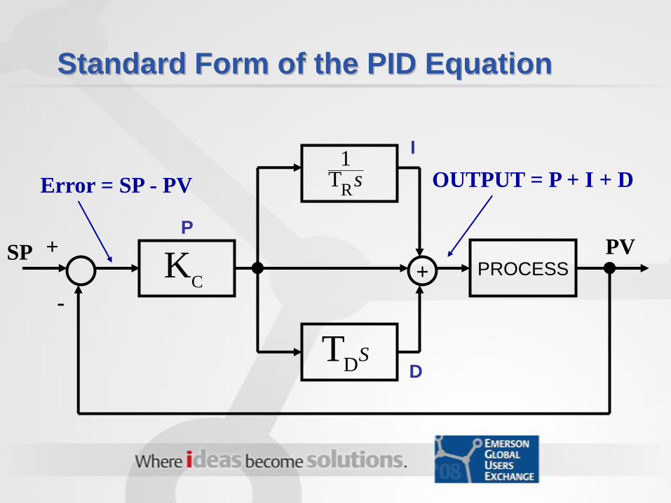
Standard Form of the PID Equation
+
-
SP+ PROCESS
PV
Error = SP - PV OUTPUT = P + I + D
P
I
DS
DT
sR
T1
CK
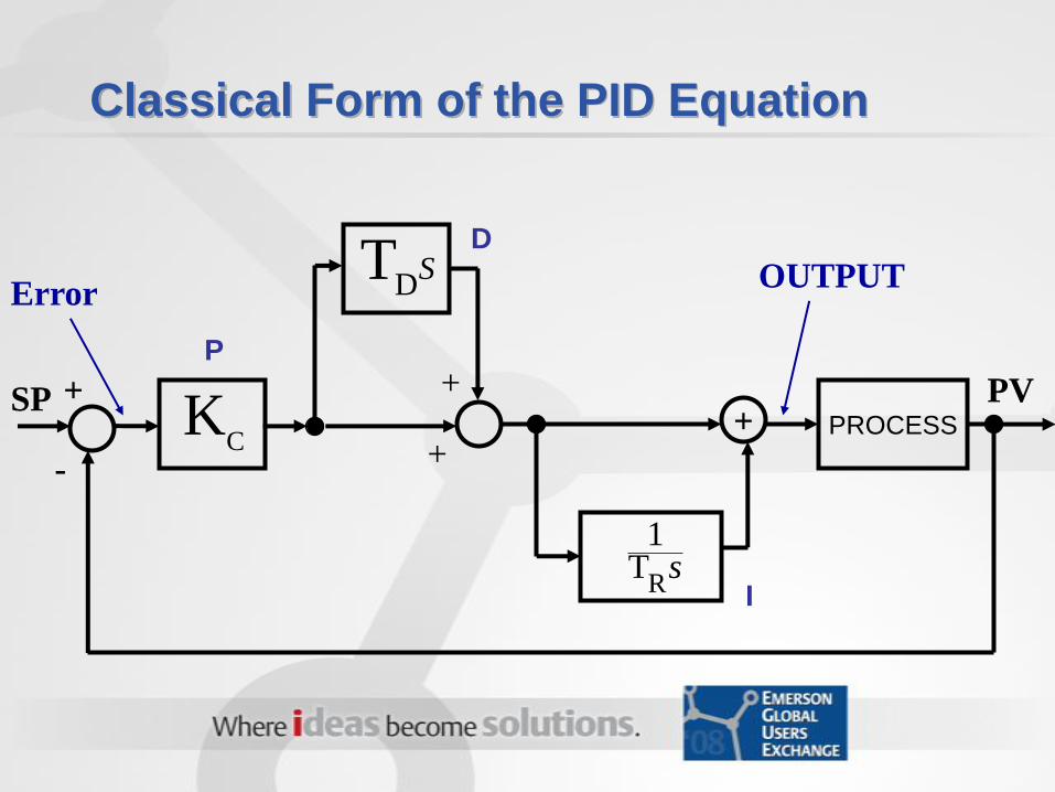
Classical Form of the PID Equation
PROCESS
PV+
-
SP
OUTPUT
+
Error
+
+
P
I
DS
DT
sR
T1
CK
PID “Form” Choice
Prior system experience
Personal Preference for Standard or Series
Series is identical to Standard form if
Derivative action is NOT used
Can impact conversion of tuning constants
from previous control system

Convert Series (Classical) to Standard
Series is identical to Standard form if Derivative
action is NOT used
TR should be time/rep & same time units as TD
Be sure to convert units after form conversion
TR Classical * TD Classical
( TR Classical + TD Classical )
KC Standard = KC Series *TR Classical + TD Classical
TR Classical
TR SeriesTR Standard =0
TD Standard =
+ TD Classical
0
0TR Series * TD Series
( TR Series + TD Series )
TR Series + TD Series
TR Series
+ TD Series
*

PID Function Block “Structure” Parameter
Used most.
Default

PID Function Block “Structure” Parameter
SP Change on Reactor feed tank level: PI on
error, D on PVController Output – Flow to reactor
SP
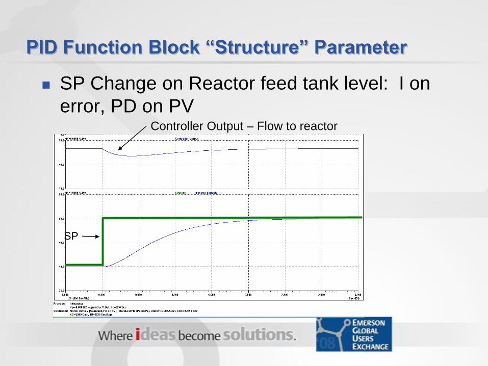
PID Function Block “Structure” Parameter
SP Change on Reactor feed tank level: I on
error, PD on PVController Output – Flow to reactor
SP
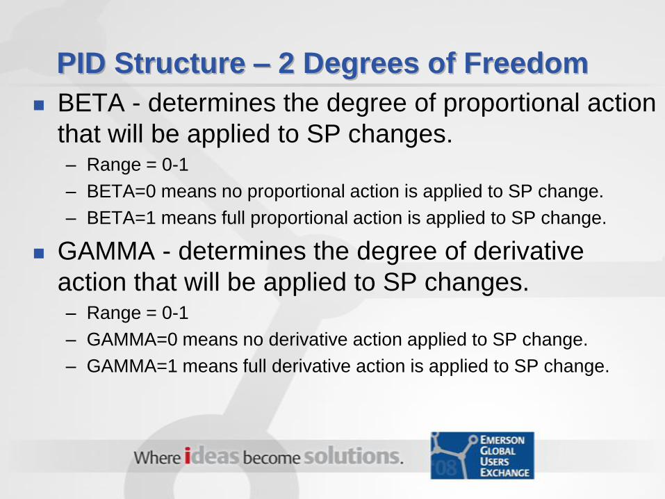
PID Structure – 2 Degrees of Freedom
BETA - determines the degree of proportional action
that will be applied to SP changes. – Range = 0-1
– BETA=0 means no proportional action is applied to SP change.
– BETA=1 means full proportional action is applied to SP change.
GAMMA - determines the degree of derivative
action that will be applied to SP changes. – Range = 0-1
– GAMMA=0 means no derivative action applied to SP change.
– GAMMA=1 means full derivative action is applied to SP change.

PID Structure – 2 Degrees of Freedom
Integral Dead Band
IDEADBAND - When the error gets within
IDEADBAND, the integral action stops. The
proportional and derivative action continue.
Same Engineering Units as PV Scale
May be used to reduce the movement of the
controller output when the error is less than
the “IDEADBAND”. For example on a level
controller that feeds the downstream unit.

Set Points Filter/Rate of Change
SP_FTIME - Time constant (seconds) of the first order SP
filter. The Set Point Filter applies in AUTO, CAS and
RCAS (not specified in BOL).
SP_RATE_DN - Ramp rate at which downward setpoint
changes are acted on in Auto mode, in PV units per
second. If the ramp rate is set to 0.0, then the setpoint is
used immediately. For control blocks, rate limiting applies
only in Auto (not CAS or RCAS).
SP_RATE_UP - Ramp rate at which upward setpoint
changes are acted on in Auto mode, in PV units per
second. If the ramp rate is set to 0.0, then the setpoint is
used immediately. For control blocks, rate limiting applies
only in Auto (not CAS or RCAS).

Set Point Limits
SP_HI_LIM- The highest SP value (EU’s)
allowed.
SP_LO_LIM - The lowest SP value (EU’s)
allowed.
Control Options – allow you to specify if SP
Limits to be obeyed in “CAS and RCAS”
Can use “Output Limits” of Master loop in
cascade pair to limit SP to Slave loop ONLY
in CAS and RCAS
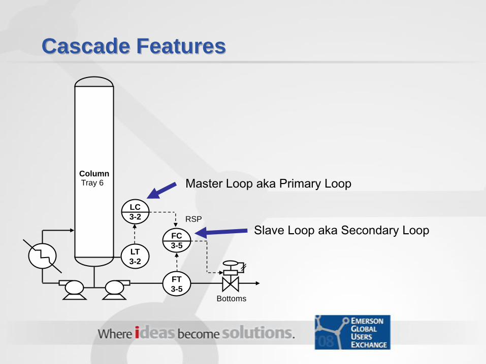
Cascade Features
Master Loop aka Primary Loop
FC
3-5
FT
3-5
LT
3-2
LC
3-2 RSP
Column
Bottoms
Tray 6
Slave Loop aka Secondary Loop

Cascade Features
Mode tracking and bumpless transfers are automatically provided through the BKCAL feature
Limited conditions in the Slave loop are taken care of through the BKCAL feature
Prevent reset windup with external reset by selecting “Dynamic Reset Limit” in FRSIPID_OPTS on the Master loop
“Use PV for BKCAL_OUT” in CONTROL_OPTS should be selected on Slave loop for use with Dynamic Reset Limit in Master

Enabling PID External Reset
Utilized most often
in the primary loop
of a cascade
Automatically
compensates for
poor secondary loop
response
Gain Scheduler
Proves up to 3 regions of different PID tuning
parameters based on a selected state variable
(output, PV, error, production rate, etc.)
Provides a smooth transition between regions
Create PID module using Module Templates:
Analog Control/PID_GAINSCHED
OR, add function to existing PID module
– Expose Gain, Reset and Rate parameters on PID
function block
– Copy all function blocks from template except the
PID FB and link as needed.
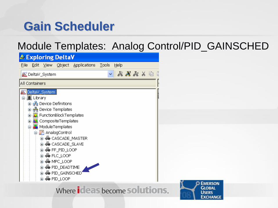
Gain Scheduler
Module Templates: Analog Control/PID_GAINSCHED
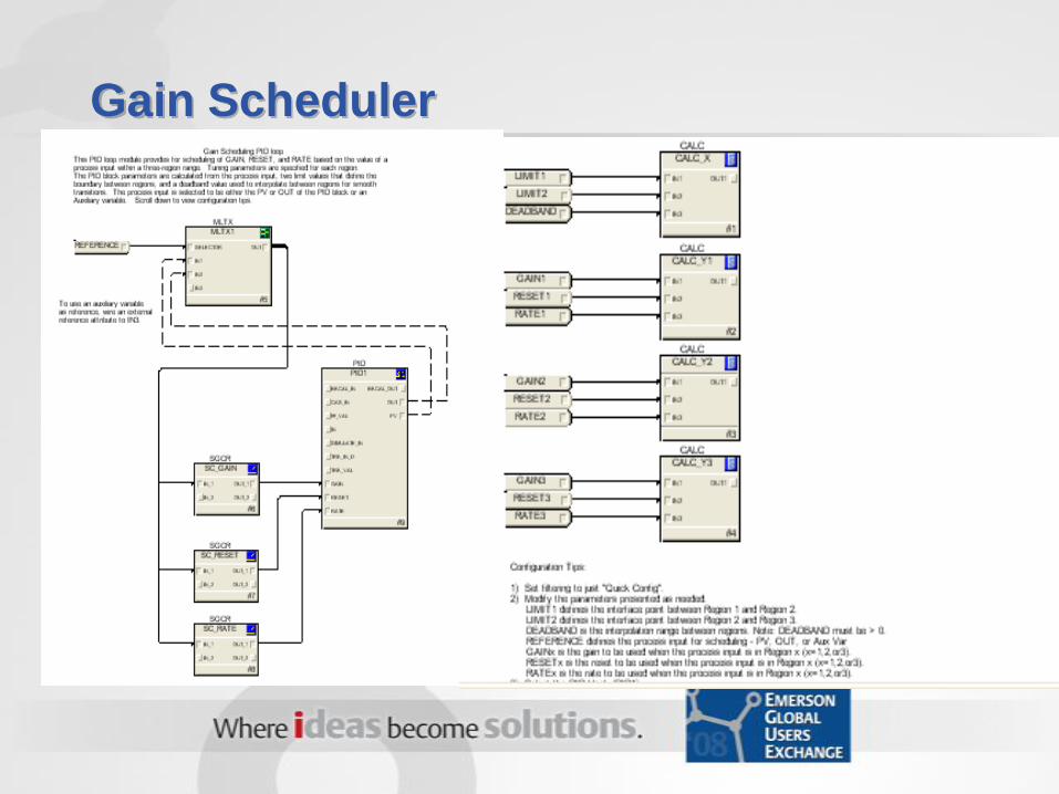
Gain Scheduler

Gain Scheduler – Detail Display

FRSIPID_OPTS: Non-linear Gain
Modifies the proportional
Gain as a function of the
error (PV-SP)
Can be used to make
the tuning more
aggressive as the PV is
farther from the set point
Can create the “error
squared” PID function
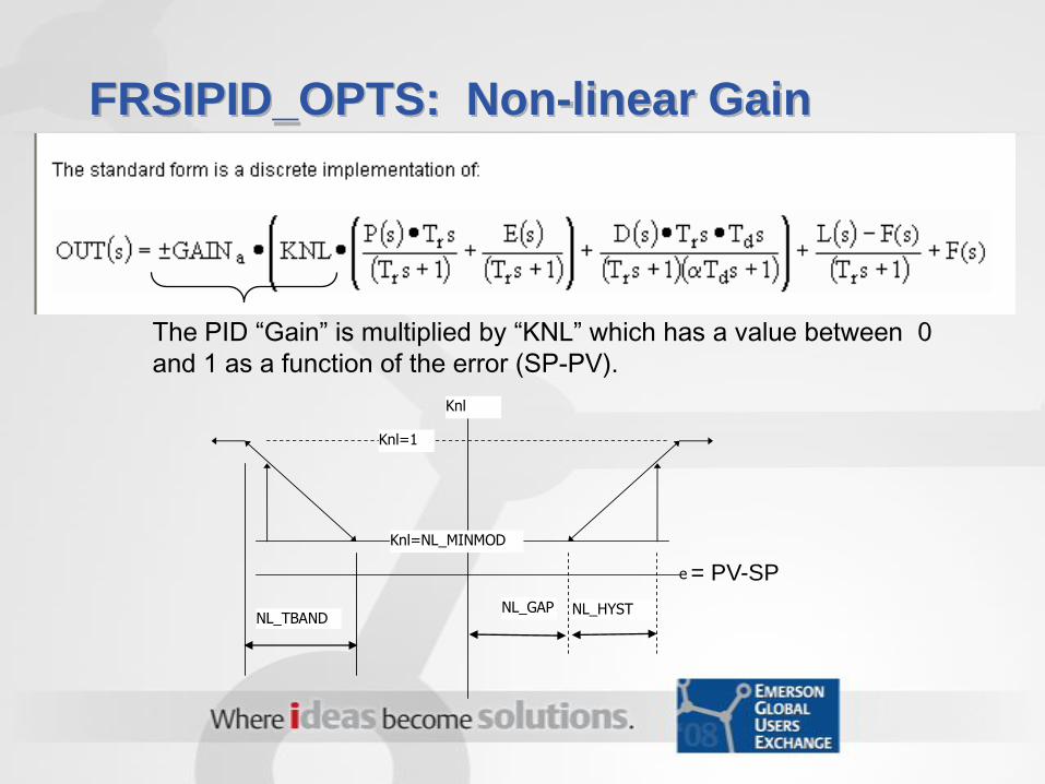
FRSIPID_OPTS: Non-linear Gain
The PID “Gain” is multiplied by “KNL” which has a value between 0
and 1 as a function of the error (SP-PV).
e
NL_GAP NL_HYST NL_TBAND
Knl=NL_MINMOD
Knl
Knl=1
= PV-SP
FRSIPID_OPTS: Non-linear Gain
The PID “Gain” is multiplied by “KNL” which has a
value between 0 and 1 as a function of the error
I typically set NL_HYST = 0
Be aware that using this feature on an integrating
process, like levels, can cause oscillations at the
reduced gain. For these applications, the reset time
should be based on “Gain*MINMOD” which will result
in a larger reset time to prevent oscillations.
For this affect on integrating processes, consider
using the Gain Scheduler
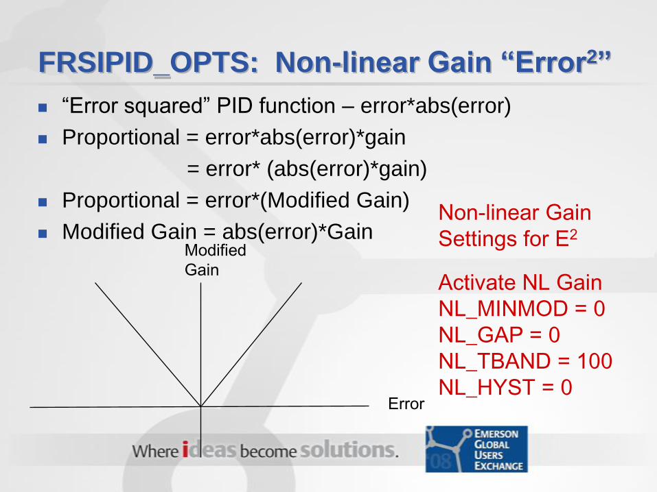
FRSIPID_OPTS: Non-linear Gain “Error2”
“Error squared” PID function – error*abs(error)
Proportional = error*abs(error)*gain
= error* (abs(error)*gain)
Proportional = error*(Modified Gain)
Modified Gain = abs(error)*Gain
Error
Modified
Gain
Non-linear Gain
Settings for E2
Activate NL Gain
NL_MINMOD = 0
NL_GAP = 0
NL_TBAND = 100
NL_HYST = 0
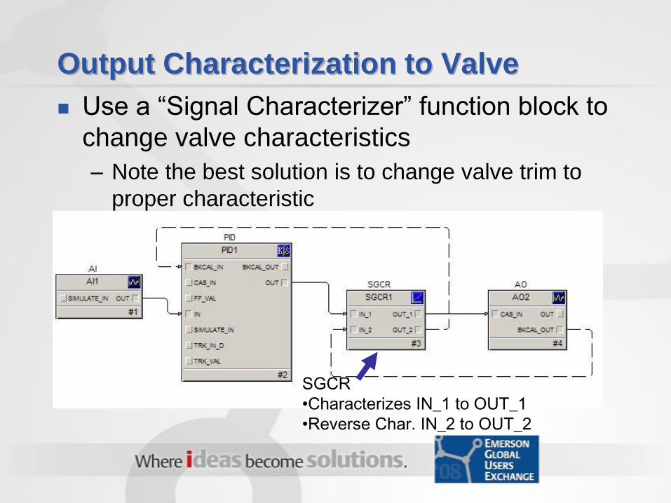
Output Characterization to Valve
Use a “Signal Characterizer” function block to
change valve characteristics
– Note the best solution is to change valve trim to
proper characteristic
SGCR
•Characterizes IN_1 to OUT_1
•Reverse Char. IN_2 to OUT_2

Output Characterization to Valve
See Books On Line for rules for the X and Y curves
Set “SWAP_2” = TRUE to provide a “reverse” characterization for the BKCAL signal (The answer in V9.3 and later is “Change X by Y axis on IN-2”.)
BOL: The SWAP_2 parameter swaps the X and Y axes used for
OUT_2. When the SWAP_2 parameter is True, IN_2 references the
CURVE_Y values and OUT_2 references the CURVE_X values. In
addition, the IN_2 units change to Y_UNITS and the OUT_2 units
change to X_UNITS.

Anti-Reset Windup Limits
Improves process recovery from saturated
conditions
On recovery from a saturated condition, when
the ARW_HI_LIM and ARW_LO_LIM are set
inside the OUT limits, the reset time will
automatically be decreased (faster) by 16X
until the OUT parameter comes back within
the the ARW limits or the control parameter
reaches setpoint.

Setting ARW limits
SP
PV
ARW_LO_LIMOUT
OUT_LO_LIM
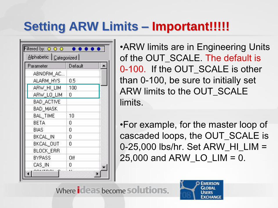
Setting ARW Limits – Important!!!!!
•ARW limits are in Engineering Units
of the OUT_SCALE. The default is
0-100. If the OUT_SCALE is other
than 0-100, be sure to initially set
ARW limits to the OUT_SCALE
limits.
•For example, for the master loop of
cascaded loops, the OUT_SCALE is
0-25,000 lbs/hr. Set ARW_HI_LIM =
25,000 and ARW_LO_LIM = 0.

Business Results Achieved
These features can be used to significantly improved
the performance of PID control
The default ARW limits of 0-100 is a common
problems for the master loop in a cascade
arrangement. Correcting the ARW limits improves
control.
These features can be used to customize the
response of the PID controller to meet process
requirements
“Difficult” process dynamics can be handled
Bottom line – Better control performance = $$$$
Summary
DeltaV has many useful control features
Watch out for default parameters (ARW limits) that
don’t match your application
Better control performance = $$$$
Questions
Where To Get More Information
Emerson Process Management Education Services
– DeltaV™ Advanced Control
Course: # 7201 - CEUs: 3.2
– DeltaV™ Operate Implementation I
Course: # 7009 - CEUs: 3.2
– EnTech - Process Dynamics, Control and Tuning
Course: # 9030 CEUs: 2.8
Emerson Process Management, Advanced
Automation Services http://www.emersonprocess.com/solutions/consulting/advancedautoma
tion/index.asp
[email protected] , 903-235-7935
About the Presenter
James Beall is a Principal Process Control Consultant with
Emerson Process Management. He has over 26 years
experience in process control, including 7 years with Emerson
and 19 years with Eastman Chemical Company. He graduated
from Texas A&M University with Bachelor of Science degree in
Electrical Engineering. His areas of expertise include process
instrumentation, control strategy analysis and design, control
optimization, DCS configuration and maintenance, control valve
performance testing and Advanced Process Control. James is a
contributing author to Process/Industrial Instruments and
Control Handbook (5th Edition, G.K. McMillan, McGraw-Hill,
New York, 1999. He is a member of AIChE and is currently the
chairman of ISA Subcommittee 75.25, Control Valve
Performance Testing.