interconnect issues in ip networkstec.gov.in/pdf/studypaper/study paper ip interconnect v4.pdf ·...
TRANSCRIPT

Telecom Engineering Center, Department of Telecommunications, Government of India
Study Paper on Interconnect Issues of IP Networks Page 1
Interconnect Issues in IP Networks
U.C Meena, ADET (IT); R. Saji Kumar, Director (IT); J.M. Suri, DDG(IT); Telecom Engineering center, Department of Telecommunications
Abstract:
This document aims to specify a network architecture capable of supporting
interconnection model for the implementation of trusted, secure and QoS compliant
IP interconnection between various communication networks. Public Switched
Telephone Network (PSTN) is transitioning to a network architecture based on
packet technology using Internet Protocol (IP) suite of protocols. A critical step in
this transition is the establishment of IP-to-IP interconnection arrangements
permitting the exchange of traffic including voice in a manner that preserves the
quality of service that consumers and businesses expect. This paper provides a basic
primer on how various services are provided by IP-networks and the challenges
associated with transition from TDM based network to IP based networks.
The paper explains IP interconnection from a micro and macro perspective.
It explains the general architectural arrangements that exist, especially during the
transition to an all-IP network, when a variety of interconnection scenarios will
occur. Further the document deals with all relevant technical issues relating to
transport protocols/capabilities, signaling protocols, media codec schemes, QoS
levels with measurements and performance needs, E.164-based addressing
schemes, Security, billing and Charging.
IP interconnection is in a relatively early stage of deployment as assessed by
the regulator as well as the market players themselves. As the migration process
towards NGNs is in progress, this issue has regulatory relevance.
Key Words: Point of Interconnection(POI), Next Generation Network, OSI Model, Media
Gateway, Signaling Gateway, SS7 Signaling, Session Initiation Protocol (SIP), Private
Peering, Public Peering, Quality of Service, SIGTRAN, Session Border
Controller(SBC), Transcoding, Common Information Rate(CIR), Excess Information
Rate(EIR), Answer Seizures Ratio(ASR), Network Efficiency Ratio(NER), ENUM,
Calling Party Network Pay (CPNP), Bill and Keep (BEK), Receiving Party Network
Pay (RPNP)

Telecom Engineering Center, Department of Telecommunications, Government of India
Study Paper on Interconnect Issues of IP Networks Page 2
1 Introduction
Interconnection is the physical and logical linking of two or more
communication networks. Interconnection allows the customers of one service
provider to communicate and exchange traffic with the customers of another service
provider. Today’s telecom network in India is a combination of the traditional
circuit switched (TDM) and packet switched (Internet Protocol (IP) based switches)
network. IP based interconnect allows different sectors/services viz. telecom, data,
radio and television, to be merged together to provide huge bandwidth, consolidate
terminating traffic and reduce long-distance charges. Now all new networks
deployed by the operators are using IP based systems because of the inherent
advantages of using common backbone infrastructure for different type of services.
The number of points of interconnection (PoIs) in an all IP network will be reduced
compared with the number of PoIs in a PSTN network.
Popularity of IP based Networks is increasing as seen by tremendous rise in
global IP traffic. However this transition has lot of challenges with regard to
architecture for IP network, interconnection issues, signaling issues, measuring and
reporting quality of service, implementation of end to end QoS, numbering and
translation of E.164 to IP, access to emergency services, charging for interconnect
and retail market, billing for services and resources and network security issues.
These issues need timely solution.
The aim of this study paper is to address these challenges which will enable
smooth migration of Telecom operators from TDM based Interconnection to IP
based Interconnection.
2 Interconnection of networks
2.1 Architecture of NGN
The ability to offer different services on a single network in a cost effective
manner lead to migration from PSTN to NGN Network. According to ITU-T definition
“Next Generation Network (NGN) is a packet-based network able to provide services
including Telecommunication Services and able to make use of multiple broadband,
QoS-enabled transport technologies and in which service-related functions are
independent from underlying transport-related technologies”.
The main feature of NGN architecture is the separation between the
transport layer of the network and the services. Enabling of new services is done by
defining it directly at the service layer without considering the transport layer
Legacy Networks are interconnected via transit and local switches in the core
part where as interconnection in NGN is at transport layer and service layer.

Telecom Engineering Center, Department of Telecommunications, Government of India
Study Paper on Interconnect Issues of IP Networks Page 3
There are three architectures of NGN namely ITU-T architecture, IMS
architecture by 3GPP and TISPAN architecture by ETSI. In all the architectures, the
Transport, Access and Control/Service functions are separated. A typical ITU-T
architecture is shown in Figure-1. Transport layer or stratum include Access
transport functions, Edge functions, Core transport functions, Gateway functions
and Media handling functions. Service stratum include Service & Control functions,
Application functions and Service user profile function. The IMS Architecture
comprises of Service or Application plane, Control or Signaling plane and User or
Transport plane. The TISPAN High Level Architecture is closely aligned with that of
3GPP.
Figure-1: ITU-T Architecture of NGN
A variety of interconnection models has evolved with the advent of IP.
Traditionally legacy networks are connected with each other to offer transit and
interconnection facility using SS7 signaling. Now a days TDM based networks are
connecting with IP based network through Media and Signaling gateways. The
Media and Signaling gateways provide the protocol conversions. NGN based
networks requires IP based interconnection having built in Quality of Service.
Networks are connected directly through physical links or indirectly through
transit. The various types of interconnect model are describe below.

Telecom Engineering Center, Department of Telecommunications, Government of India
Study Paper on Interconnect Issues of IP Networks Page 4
2.2 TDM-TDM Interconnection
Figure 2: TDM Interconnection through OSI Model
The OSI Model in Figure-2 elaborates the call setup and signal flow between
the calling party and called party through OSI model in TDM interconnection. The
application layer gets signal when the calling party initiating the call by pressing
keypads to cause tones. The presentation layer interprets and collects the dialed
digits and then sends them to the switch translation function. The session layer
establishes the call using signaling system to identify the destination switch and
notifies the called party’s serving end office switch of an incoming call. The
transport and network layers of each switch identify and reserve a bearer channel
between the two networks to carry the call using additional signaling. Once the
called party answers, the signaling system notifies both parties over the data link
layer and then connect an audio path between the calling and called parties across
the trunking network over the physical layer.
2.3 IP-TDM Interconnection
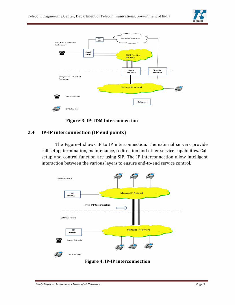
In the Figure-3, IP based call is converted to a TDM based call at the
boundary between the IP network and the circuit switched network through media
gateway, signaling gateway and call agent. A media gateway converts the voice
audio signal from the packet network’s codec to the Circuit switched network Codec.
The signaling gateway converts SIP signaling from the IP based VoIP network to the
SS7 signaling in the circuit switched network. The call agent acts as controller and
responsible for establishing the calling session. The flow will be vice versa for a TDM
network to IP network call.
Telecom Engineering Center, Department of Telecommunications, Government of India
Study Paper on Interconnect Issues of IP Networks Page 5
Figure-3: IP-TDM Interconnection
2.4 IP-IP interconnection (IP end points)
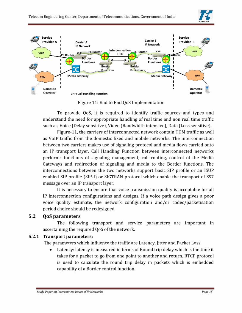
The Figure-4 shows IP to IP interconnection. The external servers provide
call setup, termination, maintenance, redirection and other service capabilities. Call
setup and control function are using SIP. The IP interconnection allow intelligent
interaction between the various layers to ensure end-to-end service control.
Figure 4: IP-IP interconnection

Telecom Engineering Center, Department of Telecommunications, Government of India
Study Paper on Interconnect Issues of IP Networks Page 6
The OSI Model of the call flow in an IP Interconnection is shown in Figure-5.
When the telephone goes off-hook, the adapter interprets the signals and, after
collecting the dialed digits, generates a SIP message to invite the called party to a
session. The adapter then sends the SIP invite message across the IP network to the
calling party’s SIP call agent. The call agent signals the destination network that
there is an incoming call attempt. The destination network signals the called party
with the appropriate session-description parameters, and, once all session
parameters are negotiated, the called-party user-agent client will initiate ringing.
Figure 5: IP interconnection using the OSI Reference Model
For voice conversations, the speech is formatted at the transport layer using
real-time transport protocol (RTP). Upon detection of RTP from the transport layer,
the IP network layer provides IP packet assembly and routing, encapsulates the RTP
payload in an IP packet, determines and inserts the destination IP address of the
recipient, and sends the assembled IP packet to the data link layer. At the data link
layer, the IP packet is encapsulated in the frame (example: Ethernet) and then sent
to the transmission network. At the receiving end, the entire process is repeated in
reverse.
The IP Interconnection can be technically direct, indirect or any to any
interconnection as described in the following sections. However, since the TDM
interconnection is already existing, the IP interconnection needs to follow the TDM
paradigm. Moreover the type of connectivity is subjected to regulatory compliances.
2.4.1 Direct interconnection:
Networks interconnect directly with each other via a private or public
peering link and generally use Border Gateway Protocol (BGP).

Telecom Engineering Center, Department of Telecommunications, Government of India
Study Paper on Interconnect Issues of IP Networks Page 7
a. Private Peering
Private peering involves direct connection between two networks. The
Figure-6 shows Network 1 connected with Network 2 through dedicated link by
using gateway routers. Here the two privately peered service providers are in a
better position to agree on capacity upgrades needed on the link to avoid
congestion.
Figure 6 – Private peering
b. Public Peering
Public peering may involve more than two operators connecting at a public
peering point as shown in the figure 7. Such Interconnect Exchange points are
generally provided by the Government. This arrangement is more suitable when
there are more number of service providers and establishment of private peering
across all the service providers become very difficult.
Figure 7 – Public peering
2.4.2 Indirect Interconnection
International connectivity comprises so many networks and it is impractical
for all the networks to directly interconnect with each other. Larger networks may
provide transit service for the delivery of packets across a network to IP addresses.
In Figure-8 two service provider are connected via a transit network to complete a
connection.

Telecom Engineering Center, Department of Telecommunications, Government of India
Study Paper on Interconnect Issues of IP Networks Page 8
Figure-8: IP transit
2.4.3 Any-To-Any Connectivity
Combination of direct and indirect interconnection achieves any-to-any
connectivity. The internet is another case of any-to-any connectivity using IP
addresses to locate internet users by word-based addressing, rather than users
having to remember large numbers of IP addresses.
2.5 Physical interconnection alternatives
The physical interface of the interconnection of Routers or the SBC’s or
Media gateways of the two networks can be either PDH-based, SDH based or
Ethernet-based (i.e. fast-Ethernet, gigabit-Ethernet or 10 gigabit-Ethernet). These
links may use copper, Optical Fiber based systems, Microwave systems or Satellite
systems. These types of interfaces may interface directly also without deploying any
systems in between.
2.5.1 PDH-based transport systems
PDH based transport systems use data rates of multiples of 2, 8, 34 or
140MBps as per ITU-T G.703, G.704 and G.705 for interconnection.
2.5.2 SDH-based transport systems
SDH based transport systems use data rates of 155.52Mbps (STM-1),
622Mbps (STM-4), 2.5Gbps (STM-16) as per ITU T Rec. G.707 for interconnection.
2.5.3 Ethernet-based transport systems
The Ethernet based interconnections use transport systems having interfaces
such as fast-Ethernet, gigabit-Ethernet, 10 gigabit-Ethernet, 40GE, 100GE etc. as per
IEEE 802.3 standards. Ethernet being the most common physical layer framing for
IP, is becoming the most popular interconnection method.

Telecom Engineering Center, Department of Telecommunications, Government of India
Study Paper on Interconnect Issues of IP Networks Page 9
With increased requirement of bandwidth for the interconnections both for
voice, data and video, DWDM based transport systems having SDH or Ethernet
based interfaces are being deployed for effective fiber utilization between two
interconnected networks.
2.6 Interconnection redundancy
The level of redundancy of a specific interconnection can be enhanced by
increasing the number of involved Border Functions. This is achieved by increasing
the number of involved PE routers using geographical separation or by increasing
the number of diverse network links involved. However the transit of traffic is
subject to regulatory compliances.
3 Challenges in Transition to IP-IP interconnection The IP networks offers greater opportunity of convergence i.e. one network
for voice, data and video. However while service providers are in a transition phase
from TDM network based interconnection to IP based interconnections they face
many difficulties and challenges. TDM networks followed CCS-7 based signaling,
fixed bandwidths per channel, universal numbering formats and generation of
CDR’s in standard formats for Billing. With the introduction of IP, all these standards
and methodologies needs to be aligned with IP based standards. Moreover, the IP
interconnection needs to be aligned with the TDM paradigm. Accordingly following
are some of the challenges being faced.
3.1 Signaling and Media function
The signaling and media function challenges are with respect to
standardization of different signaling protocols, inter-operability of codecs and
signaling protocols, call flow and transmission of various media and interworking
between the networks.
3.2 Quality of Services
TDM networks provide fixed bandwidth for a call from the originating
exchange to the terminating exchange. But in IP since the bandwidth is shared,
quality of service is a challenge. Hence the challenge is for providing the voice
quality equivalent to TDM networks, providing the end to end quality throughout
the connected networks and delivering of services as per service level agreement.
3.3 Numbering and Addressing
The deployment of IP networks and interconnection allows use of many
types of terminals and offering of many services. Even though voice services
continue to follow E.164 based numbering scheme, still this has a great impact on
the numbering plan, IP addresses as well as on the universal directory.

Telecom Engineering Center, Department of Telecommunications, Government of India
Study Paper on Interconnect Issues of IP Networks Page 10
3.4 Charging and billing
In IP networks, the CDR generation methodologies as well as the formats
have changed. However, there needs to be an equivalence in the charging models
adopted for voice calls in TDM as well as IP based interconnections. Moreover the
voice call interconnect billing needs to use the existing billing systems adopted for
TDM based Interconnect billing. In addition, the billing systems needs to adopt to
new billing requirements thrown open because of the possibility of newer services
over IP which may follow different retail charging models.
3.5 Security
The IP network including the interconnect interfaces use open protocols
which are universally accessible. So the networks are susceptible to denial of service
attacks, exposed to remote attack and data theft. Hence the challenge is in protecting
the gateways and control systems from intruders.
4 Signaling and Media function In an IP based interconnection, data flow between the interfaces of the two
networks are through administering control signals and media functions. Figure-9
shows a logical interconnection of two networks through SBC’s (The actual
connectivity may be through Edge Routers of the two networks). The SBC’s
executing the Border gateway function in both the networks, takes care of signaling,
security and protocol conversion. In the interconnected network’s various signaling
schemes are employed and the quality of voice call is maintained by using various
codecs and other protocols.
Figure 9: Interconnected at IP level via Session Border Controller

Telecom Engineering Center, Department of Telecommunications, Government of India
Study Paper on Interconnect Issues of IP Networks Page 11
4.1 Signaling function
In interconnected IP networks the protocols used for signaling and data
transfer are basic SIP, ISUP enabled SIP (SIP-I) or SIGTRAN. SIGTRAN protocol can
be interoperable on both IP and TDM networks. The protocol messages initialize,
maintain and terminate the connection between the networks. The interface of
interconnected networks should support codecs negotiation facilities and codecs
modification procedure any time during the active phase of the call.
4.1.1 SIP
SIP is a signaling communication protocol widely used for controlling
multimedia communication sessions such as voice and video calls over IP networks.
It can run on Transmission Control Protocol (TCP), User Datagram Protocol (UDP)
or Stream Control Transmission Protocol (SCTP). UDP is default for SIP Protocol but
TCP and SCTP can be used based on bilateral agreements. Some of the SIP signaling
protocol profile are the following:
i) Basic SIP profile as per RFC 3261
ii) Compact form of SIP is not used
iii) Request-URI is set
iv) Support of P-Asserted Identity header as per RFC 3325
v) Support of Privacy header as per RFC 3323
vi) Support of Diversity header as per RFC 5806
4.1.2 SIP-I
SIP-I or SIP with encapsulated ISUP is a protocol used to create, modify and
terminate communication session based on ISUP using SIP and IP networks. SIP-I
protocols allows ISUP messages to be transported over the SIP networks. SIP-I
supports ISDN bearer services including video services as well as ISDN
supplementary services such as Calling line Identification Presentation(CLIP), Call
forwarding, Call waiting, Closed User Group(CUG) etc.
4.1.3 SIGTRAN
SIGTRAN is a set of protocols defined to transport SS7 messages over an IP
Transport layer to enable interconnection between Signaling Gateway functions of
two networks. SIGTRAN protocols include Stream Control Transmission Protocol
(SCTP), MTP2 (Message Transfer Part 2) adaption layer (MP2A) and MTP3
(Message transfer Part 3) User adaption layer (M3UA). The SCCP and ISUP message
of the CCS-7 signaling can be transported over IP using M2PA, M2UA or M3UA
encapsulations.

Telecom Engineering Center, Department of Telecommunications, Government of India
Study Paper on Interconnect Issues of IP Networks Page 12
Figure 10: M2PA Adaption layer
In figure 10, M2PA transports SS7 MTP2 user signaling (MTP3 messages)
over IP using SCTP. M3UA protocol transport supports the transport of any SS7
MTP3 user signaling messages to an IP signaling point using the services of SCTP.
M2PA has relaying capabilities (i.e. it is possible to continue SS7 MTP traffic routing
beyond the end point of the M2PA connection) which makes it preferred solution
over the other protocols. M2PA also provides error discovery capability, enhancing
network performance and availability.
4.2 Media Function:
IP voice interconnection needs to support the following services namely
voice phone call using different codecs, DTMF, fax connections and modem
connection. The call between interconnected networks require RTP protocol for real
time media, RTCP and UDP protocol at the transport layer. The interface of the IP
interconnected networks allow the negotiation of codecs between the originating
and terminating service providers so the carrier has to support all mandatory
codecs. The codecs to be supported are given below:

Telecom Engineering Center, Department of Telecommunications, Government of India
Study Paper on Interconnect Issues of IP Networks Page 13
Table-1: Codecs to be supported in IP interconnection
Codec Description & Application Narrow band transmission
G.711µ-law PSTN Telephony using 64Kbps support G.729 G.729 vocoders perform voice compression at bit rates that
vary between 6.4 and 12.4 kbps. G.729 is used in wireless voice, voice-over-packet-networks, multimedia, and voice circuit multiplexing applications.
G.729A, G.729B and G.729AB
G.729A, G.729B and G.729AB are simplified versions of the G.729 codec. They use Conjugate-Structure Algebraic-Code–Excited Linear Prediction (CS-ACELP) at 8Kbps. They are used in wireless voice, voice-over-packet-networks, multimedia, and voice circuit multiplexing applications.
AMR The Adaptive Multi-Rate (AMR) codec is used for both GSM and circuit switched UMTS / WCDMA voice calls. The AMR codec operates at 7.4 to 12.2Kbps for toll quality speech.
Wide band transmission
G.722 or G.725A
7 kHz Wideband audio codec operating at 48, 56 and 64 kbit/s. It provides HD Voice with superior audio quality and clarity
AMR-WB Adaptive Multi-Rate Wideband, AMR-WB codec, also known under its ITU designation of G.722.2, is based on the AMR codec. This codec operates from 6.6 to 23.85Kbps. AMR-WB uses an ACELP basis for its operation. AMR-WB provides improved speech quality because of encoding of wider speech bandwidth. AMR-WB has a bandwidth extending from 50 - 7000 Hz
Fax transmission
T.38 using IFT protocol
T.30 media
T.38 using UDP/RTP/TCP protocol
Transport layer
4.2.1 Transcoding
Transcoding is the process of converting media stream from one codec to
another. If no common codec can be used between both end service providers, it is
the responsibility of service providers to support transcoding in order to ensure
successful voice interoperability for their services. But transcoding is suggested to
be avoided whenever possible due to the impact on speech quality and delay.
In case fixed-mobile interconnection, transcoding is recommended to be
performed by mobile service provider during the voice over IP/TDM conversion.

Telecom Engineering Center, Department of Telecommunications, Government of India
Study Paper on Interconnect Issues of IP Networks Page 14
If the call is to be routed to a TDM network, only one transcoding is
recommended and it is to be performed during the voice over IP/TDM conversion.
If a satellite link serves mobile SP’s, the SP’s mobile codec is recommended to
be used on the satellite link rather than transcoding to a different codec.
4.2.2 Dimensioning requirement
The IPv4 and IPv6 bandwidth (Bandwidth required for the codec plus over
provisioning factor) per call to ensure sufficient capacity at the interconnection is
given below:
Table 2: Bandwidth of the codec in IPv4 and IPv6
Codec Packetisation (msec)
IPv4 Bandwidth (kbit/s)
IPv6 Bandwidth (kbit/s)
G.711 20 104.720 113.520 G.729 20 43.120 51.920 G.729 40 25.960 30.360
5 Quality of Services Quality of service is a concept which cover various aspect influencing the
user’s perception about the quality of service through network parameters such as
jitter, delay, throughput, bandwidth, packet dropping and availability as well as
other factors such as terminal equipment, codecs or customer support.
PSTN using TDM transport techniques provide an end to end fixed
bandwidth channel and designed to provide a guarantee level of QOS, in contrast
with the IP based networks which provides for “best” effort QoS. IP based networks
utilizes end to end QoS mechanism including use of techniques such as
prioritization, resource reservation and admission control techniques to ensure
deterministic quality for various services. In a mixed TDM and IP network
environment the TDM QoS is to be translated to IP through the above mechanisms
to achieve the guarantee level of QOS
5.1 Requirement for end to end QoS
Quality of services mainly refers to the quality perceivable between source
and destination. Figure-11 is an example of end-to-end QoS implementation. QoS is
influenced by many factors from terminal equipment, codecs for compression,
protocols, network performance parameters, QoS technique used etc. From a
business perspective, it is essential to assure that the critical application are
guaranteed the network resources they need, despite varying network traffic load.
Telecom Engineering Center, Department of Telecommunications, Government of India
Study Paper on Interconnect Issues of IP Networks Page 15
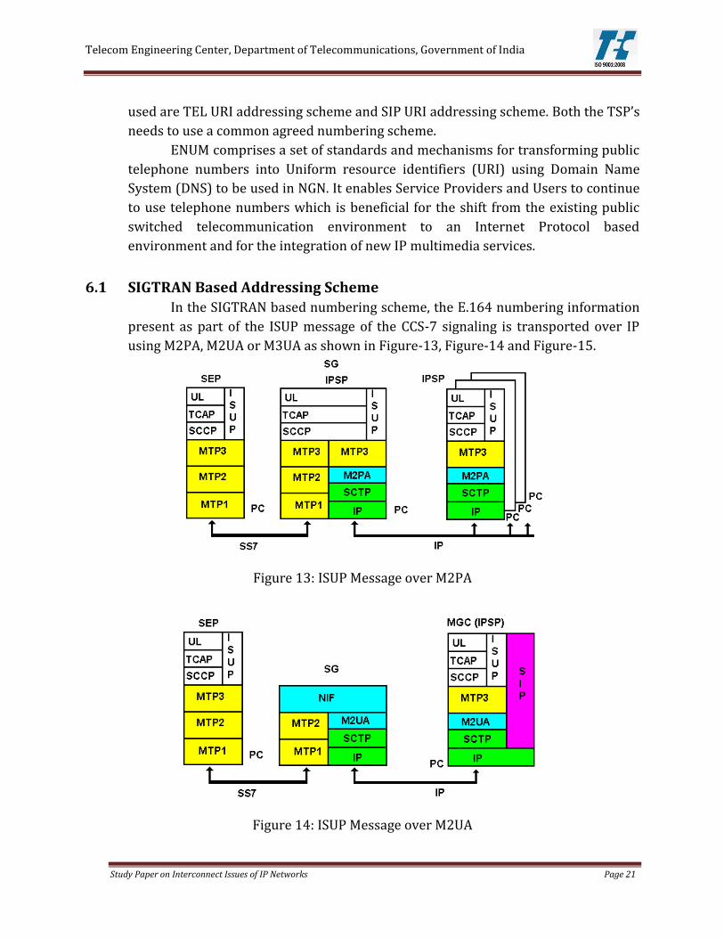
Figure 11: End to End QoS Implementation
To provide QoS, it is required to identify traffic sources and types and
understand the need for appropriate handling of real time and non real time traffic
such as, Voice (Delay sensitive), Video (Bandwidth intensive), Data (Loss sensitive).
Figure-11, the carriers of interconnected network contain TDM traffic as well
as VoIP traffic from the domestic fixed and mobile networks. The interconnection
between two carriers makes use of signaling protocol and media flows carried onto
an IP transport layer. Call Handling Function between interconnected networks
performs functions of signaling management, call routing, control of the Media
Gateways and redirection of signaling and media to the Border functions. The
interconnections between the two networks support basic SIP profile or an ISUP
enabled SIP profile (SIP-I) or SIGTRAN protocol which enable the transport of SS7
message over an IP transport layer.
It is necessary to ensure that voice transmission quality is acceptable for all
IP interconnection configurations and designs. If a voice path design gives a poor
voice quality estimate, the network configuration and/or codec/packetisation
period choice should be redesigned.
5.2 QoS parameters
The following transport and service parameters are important in
ascertaining the required QoS of the network.
5.2.1 Transport parameters:
The parameters which influence the traffic are Latency, Jitter and Packet Loss.
Latency: latency is measured in terms of Round trip delay which is the time it
takes for a packet to go from one point to another and return. RTCP protocol
is used to calculate the round trip delay in packets which is embedded
capability of a Border control function.

Telecom Engineering Center, Department of Telecommunications, Government of India
Study Paper on Interconnect Issues of IP Networks Page 16
Jitter: Absolute value of difference between the delays of consecutive
packets. RTP protocol measures accurately the live traffic which tell about
jitter effect.
Packet loss: It is the ratio between the total lost packets and the total sent
packets over a given period time. RTP protocol is used to measure packet
loss.
The first element to a QoS policy is to classify/identify the traffic that is to be
treated differently. After classification, marking tools can set an attribute of a frame
or packet to a specific value according to their service level. Classification and
marking to a frame or packet can be done by examining the parameters at various
layers. Using classification based on the DSCP value, packet marking scheme is pre
agreed by both operators. Policing tools determine whether packets are conforming
to administratively-defined traffic rates and take action such as marking, remarking
or dropping a packet.
Scheduling tools determine how a frame/packet exits a device. When a
packets enter a device faster than they can exit it, with speed mismatches, then a
point of congestion, or bottleneck, can occur and devices have buffers that allow for
scheduling higher-priority packets to exit sooner than lower priority ones, which is
commonly called queueing. Queueing algorithms are activated only when a device is
experiencing congestion and are deactivated when the congestion clears.
In a differentiated service model the traffic to a network from external
network enters through ingress node via router and switches. The network element
which forwards the traffic in a network is at interior node. At Egress node traffic is
directed towards an external network and originated from inside the host network.
Traffic in a network is subjected upon Traffic Conditioning Agreement (TCA) and
per-hop behavior (PHB). The Ingress and Egress Nodes perform both TCA & PHB
and the interior Nodes perform the PHB functions. In case of Ingress and Egress
Nodes, TCA functions are performed for the Inbound Traffic/Interface and PHB
functions are performed for the Outbound Traffic/Interface. The traffic at ingress
and egress node is also subjected to mapping from one medium to another. TCA
functions performed for the Inbound Traffic/Interfaces of Ingress/Egress Node
include traffic classification & prioritization, traffic marking, policing and shaping.
PHB functions performed for the Outbound Traffic/Interfaces of Ingress/Egress
Nodes and Interior Nodes includes Queuing, Scheduling and Congestion
Management.
The QoS actions required at IP interconnection is given in Figure-12.

Telecom Engineering Center, Department of Telecommunications, Government of India
Study Paper on Interconnect Issues of IP Networks Page 17
Figure 12: QoS actions at Interconnect Networks
The traffic between the networks is maintained by interconnection of
networks. In Figure-12 the interconnection is in between point E & point F. The
traffic at egress node of Network-I at point E and ingress node of network-II at point
F are subjected to Classification & Prioritization, Mapping of traffic from one
medium to another, Policing and Scheduling. The networks are bound by pre-
defined agreements for traffic prioritization and traffic congestion schemes.
5.2.2 Transport parameters to be agreed at the Interconnect Interface:
There need be an agreement on bandwidth profile for various services
flowing across the interface and QoS action at the interface. Some of the bandwidth
profile parameters which is to be agreed upon at the interconnection interfaces are
as follows:
i) Bandwidth assigned for each service
ii) Committed Information Rate (CIR) % for each service which is average
bandwidth for a virtual circuit guaranteed by an Service Provider (SP) to work
under normal conditions
iii) Excess Information Rate (EIR) % for each service which is an allowance of
burst bandwidth above CIR value
iv) Defining the main and alternate paths
v) Exchange of protocols for Traffic Engineered paths
vi) Interpretation method followed for the IP ToS Bits.
5.2.3 Service parameters:
These parameters help to measure the quality of service in terms of users
satisfaction, successful call setup, delivery of call and elapsed time for call setup.

Telecom Engineering Center, Department of Telecommunications, Government of India
Study Paper on Interconnect Issues of IP Networks Page 18
i) MOSCQE / R-factor: Mean opinion score is a subjective parameter defined in ITU-T
Rec. P.10 about the performance of telephone transmission system used either for
conversation or listening to spoken material. The R-Factor may be converted into an
estimated MOS which is called MOS Communication Quality Estimated or MOSCQE.
MOS is an actual user opinion score, and all measurements done by equipment are
estimates, and may differ from what actual customers would perceive.
ii) ALOC: Average Length of Conversation (ALOC) expresses the average time in
seconds of conversations for all the calls successfully setup in a given period of time.
ALOC =Time periods between sending answer and release messages
Total number of answers
In a Voice over IP environment ALOC is defined as
a) SIP protocol: ALOC is measured from the time of SIP 200 OK (in response to
an INVITE initiating a dialog) to the time of call release (SIP BYE).
b) SIP-I protocol: ALOC is measured from the time of a SIP 200 OK with an
encapsulated ANM to the time of receiving a BYE message with encapsulated
REL.
ALOC depends on the user behavior also.
iii) ASR: Answer Seizures Ratio (ASR) expresses the ratio of the number of calls
effectively answered in a given period of time against the number of call session
requests in that time.
ASR = Seizures resulting in answer signal
Total Seizures
In a Voice over IP environment ASR is defined as
a) SIP protocol: ASR is the ratio between the number of received 200 OK (in
response to an INVITE initiating a dialog) and the number of sent INVITE
initiating a dialog.
b) SIP-I protocol: ASR is the ratio of the number of received 200 OK with an
encapsulated ANM (in response to an INVITE with an encapsulated IAM
initiating a dialog) to the number of INVITE sent with an encapsulated IAM.
ASR depends on the user behavior also
iv) NER: Network Efficiency Ratio (NER) expresses the ability of a network to deliver a
call without taking into account user interferences (measure of network
performance) in a given period of time.

Telecom Engineering Center, Department of Telecommunications, Government of India
Study Paper on Interconnect Issues of IP Networks Page 19
𝑁𝐸𝑅 =Answer message or user failure
Total Seizures
In a VoIP environment NER is defined as
a) SIP protocol: NER is the ratio of the number of received responses amongst
the responses (Response 200 OK to an initial INVITE, BYE response, 3xx
response, 404, 406, 410, 433, 480, 483, 484, 485, 486 or 488 response, 600,
603 or 606 response, CANCEL message) with the number of sent INVITE
initiating a dialog
b) SIP-I protocol: NER is the ratio of the number of received responses amongst
the responses (Response with an ANM encapsulated, Response with REL
encapsulated and cause value 1, 17, 18, 19, 20, 21, 22, 28, 31, 50, 55,57, 87,
88 or 90, CANCEL message), to the number of sent INVITE with an
encapsulated IAM.
v) PGRD: Post Gateway Ringing Delay (PGRD) expresses the time elapsed between a
request for a call setup and the alerting signal for that call. The PGRD is the elapsed
time after INVITE till media is available to the remote device. It can be calculated
with the average time between sending an INVITE initiating a dialog and the first
received message of the 180 and 183 SIP Responses:
5.3 Measurement of various SLA Parameters:
a) Round Trip Delay: The RTD can be measured using RTCP and method is
prescribed in RFC 3550.
b) Packet Loss: The Packet Loss can be measured using RTCP and method is
prescribed in RFC 3550.
c) Jitter: The Jitter can be measured using RTCP and method is prescribed in RFC
3550.
d) MOS/R-factor: ITU-T Rec. G.107 defines an objective transmission rating model
(the E-model) for representing voice quality as an R-Factor, accounting for
transmission impairments including lost packets, delay impairments and codecs.
The impairment factors of the E-model are additive, thus impairments from
different network segments may be added to obtain an end-to-end value. The R-
Factor can be converted into an estimated MOS which is called MOS
Communication Quality Estimated or MOSCQE using formula in ITU-T Rec. G 107
Annex B
e) ALOC: When ALOC to a particular destination goes outside of an acceptable
range, it indicates a problem may exist for all customer calls. ALOC is not
dependent upon an individual user’s behavior during one or two calls. It shows
changes in the behavior of a majority of users indicating a widespread problem.

Telecom Engineering Center, Department of Telecommunications, Government of India
Study Paper on Interconnect Issues of IP Networks Page 20
f) NER: Session Establishment Effectiveness Ratio (SEER) in SIP is equivalent to
NER in SS7 ISUP. SEER is defined as the number of INVITE requests resulting in a
200 OK response and INVITE requests resulting in a 480, 486, or 600; to the total
number of attempted INVITE requests less INVITE requests resulting in a 3XX,
401, 402, and 407 response. The SEER is measured as per clause 4.7 of RFC 6076
g) ASR: ASR indicates a problem may exist when it goes outside of an acceptable
range for all customer calls to a particular destination. ASR is not dependent
upon an individual user’s behavior during one or two calls, but on changes in the
behavior of a majority of users indicating a widespread problem may now exist.
The equivalent of ASR in SIP defined by IETF is Session Establishment Ratio
(SER). The SER is measured as per clause 4.6 of RFC 6076
h) PGRD: This is equivalent to successful session set up Session Request Delay.
SRD is the time interval from when the first bit of the initial INVITE message
containing the necessary information is sent by the originating user agent to the
intended mediation or destination agent, until the last bit of the first provisional
response is received indicating an audible or visual status of the initial session
setup request. It is measured as per clause 4.3.1 of RFC 6076.
5.4 Suggested SLA parameters for the interconnection interface
The interconnected network service providers offers Key Performance
Indicators (KPIs) of QoS parameters according to their commercial policy. KPIs are
averaged values over a time period. The suggested value for transport and service
parameters which are being used by different international operators are given
below:
RTD: 99 % percentile or average
LOSS: 99 % percentile or average
JITTER: 99 % percentile or average
MOS: 99 % percentile
ALOC: average
NER: average
ASR: average
PGRD: 99 % percentile
6 Numbering, Addressing and Special Services The numbering for fixed and mobile networks is based on the International
Telecommunication Union (ITU)-T E.164 recommendations. The E.164 number can
be transported over the IP network using different methods, i.e. using the SIGTRAN
Protocol as part of the ISUP message or using ENUM. The other addressing schemes
Telecom Engineering Center, Department of Telecommunications, Government of India
Study Paper on Interconnect Issues of IP Networks Page 21
used are TEL URI addressing scheme and SIP URI addressing scheme. Both the TSP’s
needs to use a common agreed numbering scheme.
ENUM comprises a set of standards and mechanisms for transforming public
telephone numbers into Uniform resource identifiers (URI) using Domain Name
System (DNS) to be used in NGN. It enables Service Providers and Users to continue
to use telephone numbers which is beneficial for the shift from the existing public
switched telecommunication environment to an Internet Protocol based
environment and for the integration of new IP multimedia services.
6.1 SIGTRAN Based Addressing Scheme
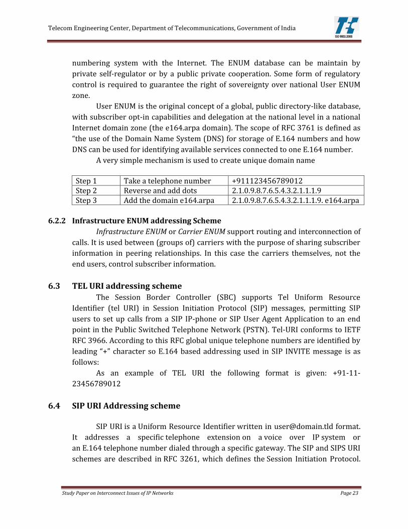
In the SIGTRAN based numbering scheme, the E.164 numbering information
present as part of the ISUP message of the CCS-7 signaling is transported over IP
using M2PA, M2UA or M3UA as shown in Figure-13, Figure-14 and Figure-15.
Figure 13: ISUP Message over M2PA
Figure 14: ISUP Message over M2UA

Telecom Engineering Center, Department of Telecommunications, Government of India
Study Paper on Interconnect Issues of IP Networks Page 22
Figure 15: ISUP Message over M3UA
The ISUP messages can also be transported over IP using SIP-T or SIP-I. SIP-T
provides two methods for the interworking between SIP and ISUP, that is,
encapsulation and mapping, which are defined by RFC3204 and RFC3398
respectively. SIP-I contains TRQ.2815 and Q.1912.5 of the ITU-TSG11 working
group. TRQ.2815 defines technical requirements for interworking between SIP and
Bearer Independent Call Control Protocol (BICC)/ISUP, including interworking
interface model, protocol capability set supported by Inter Working Unit (IWU), and
security model of the interworking interface. Q.1912.5 defines the interworking
between 3GPPSIP and BICC/ISUP, between SIP and BICC/ISUP and between SIP-I
and BICC/ISUP in detail, according to different protocol capability sets supported by
IWU at the Network-to Network Interface (NNI) on the SIP side.
6.2 ENUM addressing Scheme
In IP based network environment ENUM method has been used as one of the
addressing scheme. It consists of a simple algorithm to translate E.164 number into
ENUM number which is stored within the DNS. ENUM protocol enables convergence
between PSTN and IP and stores more than one contact information such as fax,
email etc. in the DNS record belonging to a specific ENUM number.
There are two types of ENUM- User ENUM and Infrastructure ENUM.
6.2.1 User ENUM addressing Scheme
User ENUM, also referred to as public ENUM, give the end user (the holder of
a telephone number) control over his communications and allow to provision their
records in the ENUM registry in the public domain e164.arpa. User ENUM was
conceived as the global, public directory-like database marrying the telephone
Telecom Engineering Center, Department of Telecommunications, Government of India
Study Paper on Interconnect Issues of IP Networks Page 23
numbering system with the Internet. The ENUM database can be maintain by
private self-regulator or by a public private cooperation. Some form of regulatory
control is required to guarantee the right of sovereignty over national User ENUM
zone.
User ENUM is the original concept of a global, public directory-like database,
with subscriber opt-in capabilities and delegation at the national level in a national
Internet domain zone (the e164.arpa domain). The scope of RFC 3761 is defined as
“the use of the Domain Name System (DNS) for storage of E.164 numbers and how
DNS can be used for identifying available services connected to one E.164 number.
A very simple mechanism is used to create unique domain name
Step 1 Take a telephone number +911123456789012 Step 2 Reverse and add dots 2.1.0.9.8.7.6.5.4.3.2.1.1.1.9 Step 3 Add the domain e164.arpa 2.1.0.9.8.7.6.5.4.3.2.1.1.1.9. e164.arpa
6.2.2 Infrastructure ENUM addressing Scheme
Infrastructure ENUM or Carrier ENUM support routing and interconnection of
calls. It is used between (groups of) carriers with the purpose of sharing subscriber
information in peering relationships. In this case the carriers themselves, not the
end users, control subscriber information.
6.3 TEL URI addressing scheme
The Session Border Controller (SBC) supports Tel Uniform Resource
Identifier (tel URI) in Session Initiation Protocol (SIP) messages, permitting SIP
users to set up calls from a SIP IP-phone or SIP User Agent Application to an end
point in the Public Switched Telephone Network (PSTN). Tel-URI conforms to IETF
RFC 3966. According to this RFC global unique telephone numbers are identified by
leading “+” character so E.164 based addressing used in SIP INVITE message is as
follows:
As an example of TEL URI the following format is given: +91-11-
23456789012
6.4 SIP URI Addressing scheme
SIP URI is a Uniform Resource Identifier written in [email protected] format.
It addresses a specific telephone extension on a voice over IP system or
an E.164 telephone number dialed through a specific gateway. The SIP and SIPS URI
schemes are described in RFC 3261, which defines the Session Initiation Protocol.

Telecom Engineering Center, Department of Telecommunications, Government of India
Study Paper on Interconnect Issues of IP Networks Page 24
The default port address is: 5060 for sip: unless explicitly specified in the URI. As an
example of SIP URI the following format is given:
sip: [email protected]
instructs a SIP client to make a (usually UDP) connection to voip-
provider.example.net:5060 (which may be a gateway) and ask to be connected to
the destination user at 91-11-23456789012. The gateway may require the user
REGISTER using SIP before placing this call.
6.5 Special Services Number dialing in IP Networks
6.5.1 Emergency No. dialing
In an IP interconnected network, emergency service call is required to reach
helpline call centre. The helpline call centre on receiving the call should get to know
the details i.e. the caller’s name, address and current location. An efficient operation
of emergency service require the following basic functions:
Identification of the dialed digits as emergency number
Retrieval of caller location for routing
Identification of routing destination (emergency center –
concerned authority)
Provision of caller location
Figure 16: Emergency call network setup
The Figure-16 shows three types of carrier connections i.e. wireline,
wireless and VOIP. All the three trunks connected to the helpline call center through
interconnection of networks. The wireline carrier enters their subscriber address
into automatic identification database (ALI) which is linked to subscriber telephone

Telecom Engineering Center, Department of Telecommunications, Government of India
Study Paper on Interconnect Issues of IP Networks Page 25
number. When an emergency call comes in, the switch routes the call to helpline call
centre. The helpline call centre queries ALI with caller’s phone number to determine
the caller’s location.
In emergency wireless phone call, a call identifier is attached with the calling
party number for signaling by the mobile positioning centre and call is routed based
on cellular tower location to helpline call center. When the helpline center get the
call, it queries ALI with that identifier and the mobile positioning centre ask the
mobile network for the actual location of the caller. Mobile positioning centre
respond to the ALI query with the latitude/longitude of the caller, which is
displayed on a map at the helpline call centre.
The VoIP system works in a similar way. The voice-positioning center
allocates an identifier based on the location in the self-reported location database
and sends that as the calling party telephone number with the call. The voice-
positioning center routes the call based on customer subscriber data to the
appropriate emergency services gateway, which routes the call to the selective
router based on the SIP signaling fields. The selective router routes it to a helpline
call centre based on the identifier. The helpline call centre queries ALI and is steered
to the voice-positioning center, which responds with the location from the database.
The interconnection interfaces passes the customer call as well as the
customer details to the emergency call center geographically closest to the
customer.
6.5.2 Priority Call dialing
Multilevel precedence and preemption, or MLPP, is used to assign priorities
to some calls, for example emergency calls. The MLPP is an SS7 ISUP Information
element. Hence transparent transport of ISUP messages will ensure the passage of
MLPP information.
However in case of VoIP calls, priority calling is achieved by setting the
required priority in the APN. The Allocation Retention Priority ARP is stored in the
Subscriber profile (HSS) typically on a per APN basis. Each APN is associated with an
Aggregate Maximum Bit Rate. The IP QoS and the APN QoS are mapped suitably for
maintaining the same level of QoS for the priority calls in the transport network as
well as the Radio bearer network.
7 Charging and Billing in IP interconnection Interconnect charges are the charges payable by one service provider to one
or more service providers for usage of the network resources for origination, transit
or termination of the calls. In the legacy PSTN network, interconnection charges are
normally based on per minute basis whereas packet switched IP interconnection,
the decoupling of transport and service will allow independent evolution of

Telecom Engineering Center, Department of Telecommunications, Government of India
Study Paper on Interconnect Issues of IP Networks Page 26
business model, network element and application that follow new Cost-Volume
relationship. The QoS enabled IP network supports a number of services which
require different wholesale and retail charging models for efficient utilization of
resources. The charging mechanism in an IP interconnect can be based on capacity
ordered, volume of data exchange and quality of service offered. The retail billing in
services provided by QoS enabled packet switched network is based upon generated
CDR and the volume of data exchange.
7.1 Charging Principle in IP Interconnection
The IP based network with built in QoS, supports large no of services and
hence the different charging principles may evolve on the following basis.
7.1.1 Capacity based interconnection charging
Capacity Based Charging (CBC) is based upon ordered or effectively used
interconnection capacity. In this arrangement interconnection bandwidth is agreed
and the traffic actually transported is not counted.
7.1.2 Volume based charging
With volume based pricing, operators compensate each other not on the
basis of measured minutes but based on the counted packets which pass through
the port. The unit which is paid for depends on the granularity of the volumes of
data (MB, GB, etc.).
7.1.3 Quality of service based charging
With Quality of service based charging, interconnection prices differ
according to quality parameters, such as e.g. delay, jitter, latency etc. In some
countries, in voice communications, it is a standard to pay different prices for
different quality classes of transmission. This charging system allows differentiated
pricing at the wholesale level according to the quality offered.
7.1.4 Call based Charging
This method is a combination of TDM based CDR Billing system and Quality
of Service based charging. The charging basis is on a granular basis based on call by
call charging based on call information. However in this method, being IP based, QoS
parameters also are built in to differentially charge different quality of calls.
7.2 Wholesale Charging Methodologies
There are three main types of the interconnection charging regimes.
7.2.1 Calling Party Network Pays (CPNP)
In this scheme the originating operator pays per message or per minute
charge to the terminating operator for exchange of traffic derived on the basis of

Telecom Engineering Center, Department of Telecommunications, Government of India
Study Paper on Interconnect Issues of IP Networks Page 27
7.1.2 or 7.1.4 described above. This is the most common interconnection charging
regime in case of voice calls.
7.2.2 Receiving Party Network Pays (RPNP)
In this regime, an operator receiving a message pays a per message/minute
charge to the sending operator for interconnection. This regime is less common
than CPNP. In this case the receiving operators recover the cost from its own
customer.
7.2.3 Bill and Keep (BAK)
Under this regime, also known as Senders Keep All (SKA), usually there are
no per message/minute charges between operators i.e. each network operators
agrees to terminate calls from the other network at no charge with the assumption
that traffic is roughly balanced in each direction.
7.2.4 Settlement based Interconnection (SBI)
Settlement-based interconnection is a special case of either Initiating Party
Network Pays (IPNP) or Receiving Party Network Pays (RPNP), depending on
whether the initiating network or the receiving network pays for the traffic
imbalance. This applies in the context of direct interconnection, as well as to the use
of settlement-based interconnection for transit.
7.3 Comparative efficiency of interconnection models in market situations
Table-3: Comparative efficiency of Interconnection Models
Market situation
Model for direct interconnection Generally preferred model
BAK CPNP RPNP SBI Traffic balance between peers, where this balance cannot be changed by network operators
Efficient, and avoids measurement and billing costs
Efficient (all models lead to the same net payments for IC)
BAK
Imbalanced traffic (or traffic between non peers); Stable market conditions; and Network costs
Efficient, where the efficient payments by each retail party to its network operator exactly match
Efficient when benefits accrue to initiating party only while some costs are incurred by the
Efficient when benefits accrue to receiving party only while some costs are incurred by
Efficient when fee for imbalance is chosen in the same way as the efficient fee in IPNP or
IPNP, RPNP or SBI

Telecom Engineering Center, Department of Telecommunications, Government of India
Study Paper on Interconnect Issues of IP Networks Page 28
cannot be avoided in response to IC fees.
the costs of the network that receives the payment
terminating network
the originating network
RPNP
Efficient when benefits are shared. Efficient level and direction of IC fees then depend on distribution of benefits between retail customers and distribution of costs among networks
Unstable market conditions; or Network costs can be avoided in response to IC charges
Inefficient due to inflexibility of IC fee, which is always equal to zero
Efficient if initial fee doe all traffic (INPN/RPNP) or imbalance (SBI) is chosen efficiently according to demand conditions and costs and appropriately responds to changing market conditions and costs
IPNP, RPNP or SBI
7.4 Call Scenarios in Different Types of Charging
Table-4: Call Scenarios
Method Scenario Calling Party Network Pays (CPNP)
This is the normal charging principle adopted for voice calls in India
Receiving Party Network Pays (RPNP)
This is applicable for Toll free numbers etc
Bill and Keep (BAK) In the Interconnect, in case the volume of call traffic is comparable, this method can be adopted. It is a choice of the Telecom Service Providers.
Settlement based Interconnection (SBI)
This method is typically adopted for Interconnect.
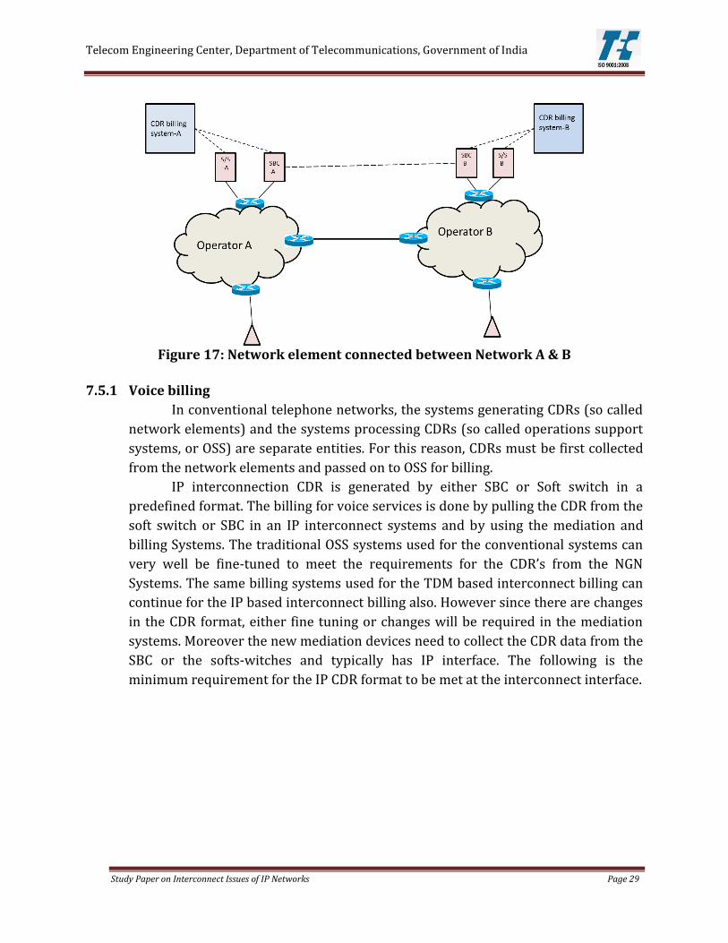
7.5 Billing in IP Interconnection
The IP based networks provides a variety of services in the form of Data,
Voice and Video services. In packet switched network the billing provision for each
of these service category varies within the QoS environment. Figure-17 shows the
interconnection of networks. The CDR’s are generated either by the SBC or the soft
switch. The billing system uses the CDR to generate bill for the users.
Telecom Engineering Center, Department of Telecommunications, Government of India
Study Paper on Interconnect Issues of IP Networks Page 29
Figure 17: Network element connected between Network A & B
7.5.1 Voice billing
In conventional telephone networks, the systems generating CDRs (so called
network elements) and the systems processing CDRs (so called operations support
systems, or OSS) are separate entities. For this reason, CDRs must be first collected
from the network elements and passed on to OSS for billing.
IP interconnection CDR is generated by either SBC or Soft switch in a
predefined format. The billing for voice services is done by pulling the CDR from the
soft switch or SBC in an IP interconnect systems and by using the mediation and
billing Systems. The traditional OSS systems used for the conventional systems can
very well be fine-tuned to meet the requirements for the CDR’s from the NGN
Systems. The same billing systems used for the TDM based interconnect billing can
continue for the IP based interconnect billing also. However since there are changes
in the CDR format, either fine tuning or changes will be required in the mediation
systems. Moreover the new mediation devices need to collect the CDR data from the
SBC or the softs-witches and typically has IP interface. The following is the
minimum requirement for the IP CDR format to be met at the interconnect interface.

Telecom Engineering Center, Department of Telecommunications, Government of India
Study Paper on Interconnect Issues of IP Networks Page 30
Table-5: IP-CDR Format: Minimum Requirements
Sl. No Information Note 1 Originating Carrier This field includes the country of the carrier. The
originating carrier may be: A domestic carrier for calls originating in a
domestic location Int’l carrier for calls originating in an int’l
location The carrier itself for calls originating in its
own network. 2 Terminating Carrier This field includes the country of the carrier. The
originating carrier may be: A domestic carrier for calls originating in a
domestic location Int’l carrier for calls originating in an int’l
location The carrier itself for calls originating in its
own network 3 Ingress TSG Number /
virtual TSG Number / IP Address
Source IP address/Port Number
4 Egress TSG Number / virtual TSG Number / IP Address
Destination IP address/Port Number
5 Call Identifier If the SIP protocol is used, Call-ID and CSeq are recorded
6 Ingress Protocol SIP, SIP-I, ITU-T C7, TUP, etc 7 Egress Protocol SIP, SIP-I, ITU-T 8C7, TUP, etc 8 Dialed Digit in CC+NN
format The called number is an E.164 number
9 Caller Number in CC+NN format, if available
A caller number may not be received. CLIR indicator, if CLI is received
10 Service Information (e.g., Toll Free, Int’l Long Distance, etc.)
This information is used for determining the billing direction. For example, outgoing International Toll Free Service is foreign billed.
11 Ingress Codec 12 Egress Codec 13 Time of Answer [Year, Month, Date, Hour, Minutes, Seconds] in IST 14 Time of Termination [Year, Month, Date, Hour, Minutes, Seconds] in IST 15 Call Disposition Cause code, SIP status code 16 ISDN Supplementary
Services For TDM CCS-7 and SIP-I Signaling calls
17 MOS Media quality of Service

Telecom Engineering Center, Department of Telecommunications, Government of India
Study Paper on Interconnect Issues of IP Networks Page 31
18 First Cell ID of Party A 19 Last Cell ID of Party A 20 Call Type (IN/OUT/SMS
IN/SMS OUT)
21 IMEI of Party A 22 IMSI of Party A 23 Type of Connection Prepaid/Post Paid 24 SMS Center Number 25 First Roaming Network
Circle ID of Party A
26 Traffic volume Optional Field which is required in case the interconnecting service providers intend to use volume based billing.
Note:
1. Billing for different types of special services like premium calling, universal number, IN based calls, Level-1 based calls etc. are to be taken care by the billing system.
2. The Fields 18 to 25 are required only for the calls originated from a mobile network
7.5.2 Streaming services
The charging model of this service should consider many parameters
including the content, the bandwidth required and the required quality of service.
Therefore, charging this service can be based on content and/or volume/duration.
7.5.3 Interactive VoD (video on demand)
User requests a video, such as a full-length movie or major network show,
from a list of available titles which may be available in another service provider
network. These videos exists on the server for a specified window of time and can
be viewed by users at any time (within that window of time). The billing of video on
demand in a packet based IP interconnection is content based.
7.5.4 Pay Per View (PPV)
The pay-per-view service is purchasing of content for specific viewing period
or number of times to be viewed, etc. according to the content on a dedicated TV
channel (e.g. paid-for-sporting event, paid-for-music). The billing of pay per view
service in a packet based IP interconnection is content based or volume based
charging.
7.5.5 Video calling
Since these services require high bandwidth and QoS provision, therefore, a
CDR based charging model is suitable for these services.
Telecom Engineering Center, Department of Telecommunications, Government of India
Study Paper on Interconnect Issues of IP Networks Page 32
7.5.6 Gaming
This service is normally an interactive application where a user may select to
play with another one. A flat rate billing works well with this service.
7.5.7 Data
In most of the cases the billing of data services is based upon the volume of
data exchange. Capacity or volume based billing could be used.
8 Security To facilitate the transition to IP interconnections there is a requirement to
ensure that connections are secured properly against security threats and fraud.
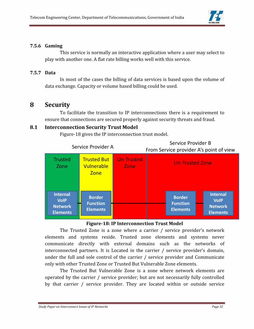
8.1 Interconnection Security Trust Model
Figure-18 gives the IP interconnection trust model.
Figure-18: IP Interconnection Trust Model
The Trusted Zone is a zone where a carrier / service provider's network
elements and systems reside. Trusted zone elements and systems never
communicate directly with external domains such as the networks of
interconnected partners. It is Located in the carrier / service provider’s domain,
under the full and sole control of the carrier / service provider and Communicate
only with other Trusted Zone or Trusted But Vulnerable Zone elements.
The Trusted But Vulnerable Zone is a zone where network elements are
operated by the carrier / service provider; but are not necessarily fully controlled
by that carrier / service provider. They are located within or outside service
Un-Trusted ZoneTrusted But Vulnerable
Zone
Trusted Zone
Internal VoIP
Network Elements
Internal VoIP
Network Elements
Border Function Elements
Border Function Elements
Un-Trusted Zone
Service Provider AService Provider B
From Service provider A’s point of view

Telecom Engineering Center, Department of Telecommunications, Government of India
Study Paper on Interconnect Issues of IP Networks Page 33
provider locations and communicate with Trusted Zone or Un-trusted Zone
elements.
The Un-trusted Zone is the zone which includes the network elements
belonging to other carriers, service provider or end customers; all other elements
not in the Trusted Zone or Trusted But Vulnerable Zone belong to the Un-trusted
Zone. They are located typically in carrier / service provider locations and
communicates with the Trusted But Vulnerable Zone only
8.2 Security Threats
Some of the threats that may be seen by carriers and service providers using
VoIP interconnections are DoS/DDoS Attack, Protocol Vulnerabilities,
Address/Identity Spoofing, Theft of Service, Rogue Media, Session Hijacking,
Network Intrusion, Internal Network Security etc
8.2.1 DoS/DDoS Attack
Denial of Service (DoS) attacks aim to make unavailable, or degrade the
performance of, network connectivity or services. A Distributed Denial of Service
(DDoS) is a type DoS attack which originates from many sources to make it more
difficult to mitigate and protect against.
8.2.2 Protocol Vulnerabilities
Protocol vulnerability threats use intentionally crafted messages to disable a
service/system or gain access to a system. This is often associated with the
production of malformed messages but may include the generation of messages that
have correct syntax but are out of sequence with other messages, which may cause
system errors, e.g. by making a software finite state machine confused. Protocol
vulnerabilities can be categorized into Protocol Implementation Vulnerabilities,
Protocol Design and Specification Vulnerabilities and Architectural Vulnerabilities.
8.2.3 Address/Identity Spoofing
Spoofing is where an attacker uses the forged identity of another system or
network element to gain unauthorized access or bypass other security mechanisms.
In an IP network this identity is typically an IP address or MAC address however,
there may be other forms of identity in use, such as dialed number prefixes or
reverse DNS records.
8.2.4 Theft of Service
Theft of service is when an end user, partner carrier / service provider or
other organization fraudulently obtains service without paying for it e.g. this may be

Telecom Engineering Center, Department of Telecommunications, Government of India
Study Paper on Interconnect Issues of IP Networks Page 34
where a 3rd party breaks the authentication scheme being used and manages to
send traffic without being identified correctly and is therefore not billed for the
traffic.
8.2.5 Rogue Media
Rogue media is when RTP traffic is received that is not associated with an
active call / session. In relation to SIP this would be where an RTP flow occurs
before a corresponding SIP session has been established, or RTP flow continues
after a SIP session has ended.
8.2.6 Session Hijacking
Session Hijacking or Man-in-the-middle (MITM) attacks are where the
attacker inserts himself in the communication path between two network elements
or networks. To the first element the attacker appears like the second element and
to the second element the attacker appears like the first element. The attacker can
act transparently, simply relaying messages between the first element and the
second element. If confidentiality protection is not used the attacker can eavesdrop
on the communication. If integrity protection is not used the attacker can
manipulate the messages. The attacker will also have the opportunity to
compromise the authentication exchange, since this will be performed prior to
confidentiality and integrity protections being in use.
8.2.7 Network Intrusion
Network Intrusion, or unauthorized access, refers to a number of different
attacks where the goal is to gain access to some resource inside the network.
Attackers can exploit many possible entrance points for network intrusion e.g. the
service provider / carrier interconnection itself, intranet or extranet tools used by
employees and partners or management networks used by software or hardware
vendors. Once an attacker has gained access into a service provider Trusted Zone
the attacker can then compromise more systems / networks, including internal
organization systems, or engage in theft of service. This can result in VoIP fraud and
the smuggling of unauthorized traffic through carrier / service provider networks
due to the inability of the carrier / service provider to adequately monitor and
detect intrusion through interconnection. In addition, the interconnection of VoIP
networks with the PSTN may introduce new risks that the PSTN is not equipped to
handle.

Telecom Engineering Center, Department of Telecommunications, Government of India
Study Paper on Interconnect Issues of IP Networks Page 35
8.2.8 Internal Security Issues
Internal security issues refer to unauthorized or improper use of network
resources attempted by users within the carrier / service provider organization.
Internal security incidents can also involve external parties who are working with
an internal user to compromise network security. Border Function Traffic Mixing is
an example in which the traffic from Customer B appear as actually coming from
Customer A. Fraud or billing disputes are the main problems associated with the
compromise of security by users within the organization.
8.3 Security Mechanism
To ensure protection against intruders certain precautionary provisions
need to be taken in an IP Interconnection. The following are the various security
mechanism available for use to improve security and mitigate threats.
8.3.1 Topology Hiding
Topology hiding is the function which allows the hiding of network element
addresses from third parties as well as obscuring the architectural layout of those
elements; this is undertaken to hide the elements within the Trusted Zone. Hiding IP
addresses can be implemented by the NAT/NAPT mechanism which is applied at
the IP level and involves the translation of addresses and ports from their original
values. NAT/NAPT makes only Trusted But Vulnerable Zone network elements
visible to the external interconnection partner.
Topology hiding using NAT/NAPT makes it hard to discover infrastructure
within the Trusted Zone to target to further an attack. Also it is often not possible to
send packets directly to devices behind the NAT/NAPT layer as networks may not
be reachable due to the use of private addresses or not being in BGP.
8.3.2 Encryption
Encryption is the encoding of data to prevent the contents from being
decoded by an unauthorized party; encryption is typically used across the Un-
trusted Zone from the Trusted But Vulnerable Zone.
IPSec provides for encryption at the network layer between two devices by
forming a tunnel and encrypts IP traffic that uses the tunnel; the devices can be
router systems, VPN devices or Border Function systems. The IPSec protocol also
provider authentication. IPSec can be used with AES encryption or other ciphers.
The TLS (Transport Layer Security) protocol is available to encrypt specific
application protocols and does not encrypt the lower layers; for the SIP protocol is
provides both authentication and encryption. It is also available for ENUM DNS and

Telecom Engineering Center, Department of Telecommunications, Government of India
Study Paper on Interconnect Issues of IP Networks Page 36
other protocols. TLS is implemented by Border Function systems or other
application layer aware network elements.
8.3.3 Authentication
Authentication is identification of the connecting party to assure that party’s
identity; authentication is used to identify elements within Un-trusted Zone from
the Trusted But Vulnerable Zone.
There are several mechanisms available for authenticating VoIP
interconnections: the use of encryption/authentication protocols such as IPSec or
TLS, the use of information within signaling messages such as prefix attached to the
dialed number or a password or the identification of the source IP address of the
incoming SIP messages. A further authentication scheme can be performed at the
IP/TCP layer by means of MD5 authentication protocol between the e-BGP
neighbors routers involved in the interconnection.
8.3.4 Access Control Lists
Access Control Lists are filters applied to packets which allow only matching
traffic to be forwarded. Filtering can use source and destination IP address and
other TCP/IP parameters such as protocol or ports. ACLs can be employed at all
zone boundaries in the trust model e.g. from the Un-trusted Zone to the Trusted But
Vulnerable Zone and also within each zone.
ACLs are applied on ingress and egress to the network to prevent unwanted
traffic being forwarded from either malicious sources or from improperly
configured equipment. ACLs should be designed to pass only traffic from allowed
services; all other traffic should be blocked.
ACLs are a common mechanism for network security. ACLs are used to defeat
attacks that target already blocked services or easy to identify attacks e.g. an attack
from a limited set of source IP addresses.
8.3.5 Reverse Path Filters
Reverse Path Filters are a type of dynamic ACL that filters incoming traffic to
ensure the traffic received is limited to that received from IP addresses that are sent
via that interface. This mechanism can be used at borders within the trust model to
prevent attacks that involve address spoofing i.e. those that involve pretending to be
an internal IP address or an IP address of a partner to exploit a security loophole.
Reverse path filters work by only allowing traffic through an interface if the
source address of the traffic matches a routing table entry that directs traffic to that
source address through the interface; it requires symmetric routing and therefore
should not be used where asymmetric routing is required. It is often deployed on a

Telecom Engineering Center, Department of Telecommunications, Government of India
Study Paper on Interconnect Issues of IP Networks Page 37
firewall or router that is close to the end device where the IP flow is terminating, for
example the Border Function system.
8.3.6 Traffic Policing
Traffic policing controls the rate of incoming or outgoing packets/requests; it
can be used for security reasons or to enforce a business agreement. Traffic policing
would typically be employed in the Trusted But Vulnerable Zone to limit the traffic
towards the Trusted zone where the CHF typically resides.
Traffic policing can be performed by routers, firewalls, DPI systems or
Border Function equipment. Traffic that is within the configured rate is called
‘conforming’ and forwarded and traffic that is in excess of the rate is called
‘nonconforming’ and discarded; there may also be burst parameters allowing traffic
that exceeds the conforming rate to be forwarded temporarily. Limits can apply at
the packet level, controlling the number of packets allowed from a particular source,
or at the application level, controlling the number of requests from a particular
source. Some network elements, such as Border Function systems, may be
application aware and able to send back protocol specific responses to
nonconforming traffic to facilitate better interworking, such as SIP 503 messages.
Traffic policing can be used to protect the Border Function systems or
downstream infrastructure from DoS attacks, from incorrectly configured partner
equipment and from ‘mass call’ events when traffic levels are too high.
8.3.7 Application Level Relaying
Application Level Relaying is performed by terminating a particular
application request session on one side of the relaying device and then relaying the
request/session to another network element, this is performed at Layer 7 by the
Application Level Relay which implements a Layer 4-7 state machine. In the case of
SIP the call itself is logically terminated on one side of the Application Level Relay
and relayed by reinitiating the call to the downstream element such as the CHF or
softswitch. The Relay therefore decodes, interprets and re-encodes any SIP message.
The Application Level Relay typically performs this function from the Un-trusted
Zone to the Trusted Zone, the Relay itself being in the Trusted But Vulnerable Zone.
For SIP/SIP-I calls or sessions the Border Functions system will normally
provide Application Level Relaying.
Application Level Relaying is useful for preventing protocol vulnerabilities
from reaching the CHF or downstream network and to allow signaling manipulation
that may be required by the CHF or downstream network. It is essential part of
security for VoIP interconnections.

Telecom Engineering Center, Department of Telecommunications, Government of India
Study Paper on Interconnect Issues of IP Networks Page 38
8.3.8 Deep Packet Inspection
DPI devices provide the ability to look into the payload that is carried by the
packet and use the contents to perform filtering or rate control; this means that the
device is able to look at the information carried in the application layers, even
though the device may not be actively participating at the application layer. DPI
devices are distinct from application level relaying as they do not contain
application implementations but provide the ability to decode the application. DPI
devices are useful to protect borders between zones in the trust model, most
commonly from the Un-trusted Zone to Trusted But Vulnerable Zone.
DPI devices are used for the separation of traffic of malicious intent from
legitimate traffic that should be processed by the network; this can be done in
situations where simple ACL or traffic policing are not sufficient to perform the task
due to forged IP addresses or TCP/UDP ports or header information that varies in a
randomized manner. DPI devices have the ability to create new attack signatures
based on baseline traffic analysis. Traffic is sampled during periods of normal
network operation and a normal baseline profile is constructed for the network. The
device can then monitor the network and shut off traffic sources that are outside the
normal baseline or control the injection of traffic into the network.
DPI is useful for dealing with protocol vulnerabilities and exploit attacks
which are identified by protocol state etiquette or specific byte or text string
patterns within incoming traffic.
8.3.9 Secure RTP (SRTP)
The SRTP protocol encrypts RTP media packets and provides authentication
and integrity for those packets; it is described in RFC 3711. It would be used to
communicate with Un-trusted Zone elements to protect from Rogue Media and
Session Hijacking type attacks.
SRTP can be implemented by either the Border Function or MG systems and
requires agreement as to the encryption standard to be used. It also requires master
keys to be exchanged between SRTP endpoints either manually or using the ZRTP
protocol.
8.3.10 DNS Security
DNS Security provides an additional layer of security for DNS clients by
digital signing DNS query responses so that the client implementation knows that
the DNS response has been received from the expected source. In particular it
provides protection against MITM attacks on DNS.

Telecom Engineering Center, Department of Telecommunications, Government of India
Study Paper on Interconnect Issues of IP Networks Page 39
DNS Security is implemented by the ENUM/DNS server digitally signing the
query responses using Digital signature algorithms. The signature itself is then
contained in new resource record type in the DNS query response.
8.3.11 Media Filtering
Media filtering, also termed ‘Pinholing’, is a dynamic ACL technique for
filtering RTP protocol packets. It can be employed at zone boundaries in the trust
model e.g. from the Un-trusted Zone to the Trusted But Vulnerable Zone.
Normally deployed in addition to static ACLs, media filtering is accomplished
by looking at the signaling messages during call setup and then allowing RTP traffic
associated with the call through the ACL. This is done by detecting the RTP source
and destination IP addresses/ports. Once the call has finished the filter entry is
removed preventing additional traffic from entering the network. Media Filtering
can be applied by a firewall or router device or can be performed by Border
Function devices directly.
This technique is useful for protecting media from rogue media attacks as
well as preventing DoS attacks that may exploit RTP UDP packets.
8.3.12 Firewalls
Firewalls are general security devices that have a variety of features:
topology hiding, encryption, ACLs, DPI, application level relaying etc. Firewalls can
be employed at all zone boundaries in the trust model e.g. from the Un-trusted Zone
to the Trusted But Vulnerable Zone.
There is large diversity in the way firewalls can be implemented and used.
The simplest usage is to provide basic packet filtering at Layers 3 through 5,
however implementations may also perform application level relaying and packet
inspection. In VoIP networks these functions may often be provided by the Border
Functions system rather than a dedicated firewall device.
8.3.13 Intrusion Detection Systems
IDS are devices or software applications that aim to detect unauthorized
access to network resources primarily for the purpose of stopping network
intrusion attacks. IDS can be employed at the major zone boundaries in the trust
model e.g. from the Un-trusted Zone to the Trusted But Vulnerable Zone.
There are two common types of IDS: host based systems that analyze log files
and system files and network based systems that monitor network traffic by packet
capture. Both systems may be combined to provide a better picture of network
security incidents. When an attack is detected the IDS can be configured to inform

Telecom Engineering Center, Department of Telecommunications, Government of India
Study Paper on Interconnect Issues of IP Networks Page 40
network operators or can automatically respond by creating dynamic ACL entries or
configuring other devices to respond to the event.
IDS can also be used to detect other forms of attack as well as intrusions. IDS
capabilities are also a feature of DPI equipment and can be found in products
together.
8.3.14 Device Hardening
Device hardening is set of techniques to ensure elements are less vulnerable
to security exploits which may result in a network intrusion or make DoS attacks
easier to accomplish; these techniques seek reduce the attack footprint of the
systems. Device hardening is applicable to all network elements in the trust model.
One method of device hardening is to turn off unused network services to
prevent them being open to access by unauthorized parties; these services might be
unused protocol interfaces e.g. H323 on a Border Function system that is only
configured for SIP or management interfaces, such as web management.
Hardening is usually applied to general computing resources involved in
service delivery, but the techniques can also be applied to specialist elements such
Border Function systems or routers. These techniques are primarily useful against
network intrusion but can also help prevent DoS attacks.
8.3.15 Logging and auditing
Logging and the auditing of the logs is a basic security practice. Logging and
auditing processes are applicable to all network elements in the trust model.
Syslog or other data produced should be stored in a central logging system to
allow searching and auditing. It is important to make sure that all devices in the
network have synchronized clocks to ensure that log information can be correlated.
Auditing of log information can be performed using the central logging system.
It is important to be able to log network events and traffic flows to build a
complete picture of the current operating state of the network. This becomes
essential important during security incidents. It is also important to audit log
information to identify incidents as early as possible to allow corrective action.
8.3.16 Security Information and Code Updates
Using security alert information and applying code updates are basic security
practices. Security information and code updating processes are applicable to all
network elements in the trust model.
There are many sources of security information provided by equipment
vendors and external organizations such as the CERT organizations. Organizations

Telecom Engineering Center, Department of Telecommunications, Government of India
Study Paper on Interconnect Issues of IP Networks Page 41
can use the information to plan immediate responses and plan software updates to
correct security problems. It is common practice to monitor information sources
and then mitigate vulnerabilities by using ACLs or other tools; in the longer term
software updates are performed.
8.4 Security mechanism recommendations
a) It is recommended that the SIP/SIP-I interface implement ACL, RPF, Device
Hardening, Logging & Auditing, Security information and Code updates, Authentication, Application level relaying, Topology hiding and Traffic Policing.
b) It is recommended that the SIGTRAN interface implement ACL, RPF, Authentication, Device Hardening, Logging & Auditing, Security information and Code updates, Topology hiding and traffic policing.
c) It is recommended that the RTP interface implement ACL, RPF, Device Hardening, Logging & Auditing, Security information and Code updates, Authentication, Media Filtering and Topology hiding.
d) It is recommended that the Routing & Addressing Query interface implement ACL, RPF, Authentication, Device Hardening, Logging & Auditing, Security information and Code updates and traffic policing
e) It is recommended that in case of use of public internet for interconnection i.e. the international connectivity etc, encryption may be used in addition to the above security requirements.
9 Recommendations
9.1 Minimum Requirements to be met at the IP interconnect
a) Support of basic SIP, ISUP enabled SIP (SIP-I) and SIGTRAN protocols for signaling and data transfer.
b) Transcoding: The transcoding requirements are given in para 4.2.1 1) Avoid transcoding whenever possible due to the impact on speech quality
and delay.
2) Perform transcoding by mobile service provider during the voice over
IP/TDM conversion in case fixed-mobile interconnection
3) Perform transcoding only once during the voice over IP/TDM conversion if
the call is to be routed to a TDM network.
4) If a satellite link serves mobile SP’s, consider using the SP’s mobile codec on
the satellite link rather than transcoding to a different codec.

Telecom Engineering Center, Department of Telecommunications, Government of India
Study Paper on Interconnect Issues of IP Networks Page 42
c) The QoS parameters requirement at the Interconnect Interface. The details are as
per para 5.2.2
1) Bandwidth assigned for each service
2) Committed Information Rate (CIR) % for each service which is average
bandwidth for a virtual circuit guaranteed by an Service Provider (SP) to
work under normal conditions
3) Excess Information Rate (EIR) % for each service which is an allowance of
burst bandwidth above CIR value
4) Defining the main and alternate paths
5) Exchange of protocols for Traffic Engineered paths
6) Interpretation method followed for the IP ToS Bits.
d) Minimum bandwidth for connectivity may be 2 GE Ports e) E.164 based numbering scheme over SIGTRAN interface is to be used for
PSTN/PLMN calls. f) The interconnection interfaces needs to pass the customer call, location
information as well as the customer details to the emergency call center geographically closest to the customer when the same is established.
g) The priority calling is implemented using ISUP messages or the IP QoS and APN QoS method. These ISUP messages or the QoS information of the packet needs to be transparently passed and honored across the Interconnect while implementing the Priority calls
h) The format for minimum required IP CDR for VoIP calls is given in Table-5 of para 7.5.1
i) The security requirements to be implement at the interconnect interface are: 1) Implement ACL, RPF, Device Hardening, Logging & Auditing, Security
information and Code updates, Authentication, Application level relaying,
Topology hiding and Traffic Policing at the SIP/SIP-I interface.
2) Implement ACL, RPF, Authentication, Device Hardening, Logging &
Auditing, Security information and Code updates, Topology hiding and
traffic policing at the SIGTRAN interface.
3) Implement ACL, RPF, Device Hardening, Logging & Auditing, Security
information and Code updates, Authentication, Media Filtering and
Topology hiding at the RTP interface.
4) Implement ACL, RPF, Authentication, Device Hardening, Logging &
Auditing, Security information and Code updates and traffic policing at the
Routing & Addressing Query interface
5) Use encryption in addition to the above security requirements in case of
use of public internet for interconnection i.e. the international connectivity
etc.

Telecom Engineering Center, Department of Telecommunications, Government of India
Study Paper on Interconnect Issues of IP Networks Page 43
9.2 Requirements which can be part of the Interconnect Agreement
between Service Providers
a) The Interconnection device between the two networks can be Routers or the SBC’s or Media gateways. The physical interface of the interconnection can use either DWDM-based or PDH-based, SDH based or Ethernet-based (i.e. fast-Ethernet, gigabit-Ethernet or 10 gigabit-Ethernet). These links may use copper, Optical Fiber based systems, Microwave systems or Satellite systems. The Interconnection methods are given in para 2.5.
b) The codecs which can be supported are given as per Table-1 of para 4.2. c) The suggested SLA parameters at the Interconnect Interface are given in para 5.4.
However the exact requirements are based on regulatory compliances. d) The E.164 numbering information present as part of the ISUP message of the CCS-
7 signaling are transported over IP by SIGTRAN using M2PA, M2UA or M3UA. Exact method need be specified by the Service Providers in the Interconnect Agreement.
e) For an end to end VoIP call scenario, any one of the Infrastructure ENUM, SIP-URI or Tel-URI numbering schemes can be implemented between the Interfaces. Exact method need be specified by the Service Providers in the Interconnect Agreement.
10 Conclusion The communication industry is going through a period of explosive change
that is both enabling and driving the convergence of services. In this regard IP
interconnection is critical for the transition to an ‘All IP system’ in Core and access
part of network.
This paper deals with the technology, processes and method that help in
overcoming challenges of transition from TDM interconnect to IP interconnect. The
important challenges relating to IP interconnect like the connectivity, Signaling and
Media, Numbering and Addressing, Quality of Service, Charging and Billing and
Security along with other related issues are dealt in this paper. A summary of
requirements to be met at the Interconnect interface are also given in this paper.
It is recommended that this transition be managed in a transparent manner
allowing equal opportunity for all the players under the auspices of the regulator in
order to avoid major obstacles leading to a major competition distortion.

Telecom Engineering Center, Department of Telecommunications, Government of India
Study Paper on Interconnect Issues of IP Networks Page 44
11 Reference
i) International Interconnection Forum for Services over IP, “Technical
Interconnection Model for International Voice Services”, rel.2, May 2009.
ii) “Solutions for implementing IP-based interconnections for the international
wholesale industry”, i3 Forum, ETSI Workshop on NGN Interconnection of
Services Standardization, Sophia Antipolis, 2008.
iii) Final Report on IP interconnection, European Regulatory Group, Project Team
on IP-Interconnection and NGN ERG (07) 09.
iv) ERG Common Statement on Regulatory Principles of IP-IC/NGN Core – A Work
Program towards a Common Position.
v) Telecom Decision CRTC 2009-139 CRTC Interconnection Steering Committee –
Consensus Items – IP to IP Interconnection Guidelines.
vi) Economic study on IP interworking by CRA international.
vii) Agarwal, A. [1991]. “Limits on interconnection network performance,” IEEE
Trans. On Parallel and Distributed Systems 2:4 (April), 398–412.
viii) International Interconnection Forum for Services over IP, Technical interconnect
model release 5 final 2012-5-3 rel may 2012.
ix) The Transition to an All-IP Network: A Primer on the Architectural Components
of IP Interconnection by Joseph Gillan and David Malfara May 2012 NRRI 12–05.
x) International Interconnection Forum for Services over IP, White Paper Security
for IP Interconnections (Release 1.0) May 2011
12 Glossary of Terms 3GPP : 3rd Generation Partnership Project
ACELP : Algebraic Code-Excited Linear Prediction
ACL : Access Control List
ALI : Automatic Identification Database
ALOC : Average Length of Conversation
AMR : Adaptive Multi Rate
AMR-WB : Adaptive Multi-Rate Wideband
APN : Access Point Name
ARP : Allocation Retention Priority
ASR : Answer Seizures Ratio
BEK : Bill and Keep
BGP : Border Gateway Protocol
BICC : Bearer Independent Call Control Protocol
CBC : Capacity Based Charging

Telecom Engineering Center, Department of Telecommunications, Government of India
Study Paper on Interconnect Issues of IP Networks Page 45
CCS 7 : Common Channel Signaling System 7
CCSP : Call Control Signaling Path
CDR : Call Dialing Record
CERT : Computer Emergency Response Team
CHF : Call Handling Function
CIR : Common Information Rate
CLI : Calling Line Identification
CLIP : Calling line Identification Presentation
CNG : Comfort Noise Generator
CPNP : Calling Party Network Pay
CUG : Closed User Group
DoS : Denial of Service
DDoS : Distributed Denial of Service
DNS : Domain Name System
DPI : Deep Packet Inspection
DTMF : Dual-Tone Multi-Frequency
DTX : Discontinuous Transmission
DWDM : Dense Wavelength Division Multiplexing
EIR : Excess Information Rate
ETSI : European Telecommunications Standards Institute
FR : Full Rate
GB : Gigabyte
GE : Giga bit Ethernet
GSM : Global System for Mobile Communications
HD : High Definition
HR : Half Rate
IAM : Initial Address Message
IC : Interconnection Charge
IMS : IP Multimedia Subsystem
IP : Internet Protocol
IPv4 : Internet Protocol version 4
IPv6 : Internet Protocol version 6
IPsec : Internet Protocol Security
ISDN : Integrated Services Digital Network
ISP : Internet Service Provider
ISUP : ISDN User Part
ITU-T : International Telecommunications Union – Telecommunication
IWU : Inter Working Unit
KPI : Key Performance Indicator

Telecom Engineering Center, Department of Telecommunications, Government of India
Study Paper on Interconnect Issues of IP Networks Page 46
MAC : Media Access Control
MB : Megabyte
Mbps : Megabit per Second
MG : Media Gateway
MITM : Man-in-the-middle
MLPP : Multilevel Precedence and Preemption
MOS : Mean Opinion Score
MOSCQE : Mean Opinion Score–Conversational Quality, Estimated
MP : Media Path
msec : millisecond
MTP2 : Message Transfer Part 2
MTP3 : Message Transfer Part 3
M2PA : MTP2 User Peer-to- Peer Adaption Layer
M3UA : MTP3 User Adaption Layer
NATP : Network Address and Port Translation
NER : Network Efficiency Ratio
NGN : Next Generation Network
NNI : Network-to Network Interface
OSI : Open Systems Interconnection
OSS : Operations Support System
PDH : Plesiochronous Digital Hierarchy
PHB : Per Hop Behavior
PE : Provider Edge
PGRD : Post Gateway Ringing Delay
POI : Point of Interconnection
PPV : Pay Per View
PSTN : Public Switched Telephone Network
QoS : Quality of Service
RFC : Request for Comment
RFP : Reverse Path Filter
RPNP : Receiving Party Network Pay
RTCP : Real Time Transport Control Protocol
RTD : Round Trip Delay
RTP : Real Time Transport Protocol
SBC : Session Border Controller
SBI : Settlement based Interconnection
SCCP : Signaling Connection Control Part
SCTP : Stream Control Transmission Protocol
SDH : Synchronous Digital Hierarchy

Telecom Engineering Center, Department of Telecommunications, Government of India
Study Paper on Interconnect Issues of IP Networks Page 47
SER : Session Establishment Ratio
SGW : Signaling Gateway
SKI : Senders Keep All
SIP : Session Initiation Protocol
SP : Service Provider
SRTP : Secure RTP
SS7 : Signaling System No 7
STP : Signal Transfer Point
TCA : Traffic Conditioning Agreement
TCP : Transmission Control Protocol
TDM : Time Division Multiplexing
TLS : Transport Layer Security
TISPAN : Telecommunications and Internet converged Services and Protocols
for Advanced Networking
ToS : Type of Service
TSG : Trunk Group
TSP : Telecom Service Provider
TUP : Telephone User Part
UDP : User Datagram Protocol
UMTS : Universal Mobile Telecommunications System
URI : Uniform Resource Identifier
VAD : Voice Activity Detection
VOIP : Voice over IP
WCDMA : Wideband Code Division Multiple Access