“intelligent” monitors hf 80/1 and hf 80/2 - tractel.com · “intelligent” monitors hf 80/1...
TRANSCRIPT

“Intelligent” monitors HF 80/1 and HF 80/2
Operating
and
Equipment inaccordance withCE directivesMaintenance
Instructions
042001003 – 04/03
®
®
2
CONTENTS
GENERAL WARNING 3
INSTALLATION AND CONNECTION OF MONITOR HF80/1 4
CONNECTION OF ELECTRONIC LOAD CELLPOWER SUPPLY CONNECTION 5
TEST FUNCTION 6
CONNECTION LAYOUT1 SAFETY TRIP POINT + 1 INTERMEDIATE TRIP POINT 7
CONNECTION LAYOUT1 SAFETY TRIP POINT + 1 SLACK WIRE ROPE TRIP POINT 8
GRAPHIC REPRESENTATION OF A LOADING CYCLE 9
DEFINITIONS AND ABBREVIATIONS 10
ADJUSTMENTS AND/OR MANUAL CORRECTIONOF PARAMETERS OF MONITOR HF80/1 - SETUP N°1 11
AUTOMATIC SETTING OF SAFETY TRIP POINT FORMONITOR HF 80/1 - SETUP N° 2 12
AUTOMATIC SETTING OF SAFETY TRIP POINT ANDINTERMEDIATE TRIP POINT FOR MONITOR HF80/1 - SETUP N°2 13
AUTOMATIC SETTING OF SAFETY TRIP POINT AND SLACK W.ROPETRIP POINT FOR MONITOR HF80/1 - SETUP N°2 14
SETTING MORE THAN 2 TRIP POINTS 17
CONNECTING SEVERAL LOAD CELLS TOGETHER 18
ADJUSTMENT OF ZERO AND GAIN POTENTIOMETERS 19
MESSAGES 21
TROUBLESHOOTING 22
INSTALLATION AND CONNECTION OF MONITOR HF80/2 23

®
®
3
GENERAL WARNING
1 - Reading and fully understanding the technical data sheets relating to thisequipment is essential for the best use of this high technological materialthat you have received. All the technical data sheets are available onrequest.
2 - Before installing and operating Dynasafe ® equipment it is essential for thesafe and correct operation of the material that this manual be read andfully understood and that all the instructions be followed. This manualshould be made available to every operator. Extra copies of this manualwill be supplied on request.
3 - The installation and operation of Dynasafe ® equipment should only becarried out in accordance with the appropriate health and safety at workregulations.
4 - Never apply to the Dynasafe ® a load or an effort in excess of the workingload limit, and never use it for an operation for which it is not intended.
5 - TRACTEL SA declines any responsibility for the consequences ofdismantling or altering the machine by any unauthorized person.
6 - Dynasafe ® equipment must not be used in explosive atmospheres.
7 - Dynasafe ® equipment must only be used in a system designed for liftingpeople after ensuring that the appropriate operating coefficients have beused in accordance with the current regulations.
8 - Prior to the use of Dynasafe ® equipment with complementary equipmentrelaying the signals to an operating system, the user or installer of thissystem should carry out a specific risk analysis of the operating functions.The appropriate measures should be taken to obviate the risks identified.

®
®
4
INSTALLATION AND CONNECTION OF MONITOR HF80/1
TERMINALS
-01-02-03-04 Sensor -15 - 16 Power supply 220 (US : 48) Vac
-05 - 06 Flashing light -15 - 17 Power supply 380 (US : 110)Vac
-06 - 07 Alarm -18 - 19 Contact NO (10 A/220 Vac)
-08 - 09 Contact NO (10 A/220 Vac) -19 - 20 Contact NC (10 A/220 Vac)
-09 - 10 Contact NC (10 A/220 Vac)
- Mount the HF80/1 monitor to the "DIN" rail in the electrical control box containing the liftingcontrols.
- Connect the monitor in accordance with the layout above. Observe the correct polarity.Any error in connecting the terminals may cause damage to certain electronic components.
- Connect the electronic alarm, HF90/1, to terminals 06 and 07 taking care to observe the correctpolarity. The alarm function is desactivated automatically 15 seconds after the detection of anoverload condition.
- Wire the electronic flashing light, HF90/2, to terminals 05 and 06, taking care to observe thecorrect polarity. This flashing light function remains active whilst there is an overload condition.
NOTE : It is possible to compensate for the dynamic effects which on lowering could triggerthe alarms by wiring terminals 11, 12 and 13,14 as for the HF80/2 (see page 23).
Figure 1
0201 03 04 05 06 07 08 09 10
1211 13 14 15 16 17 18 19 20
SS E
RS
232
OFFON
OFFON
HI
LO
0 220 380 NO C NC
0+ 18 Vcc
0 NO C NCS –12V +12V 0V
MONITEUR HF80 dynasafe
(see details on following page)
Sensor Relays
Power supply Relays
®
®
5
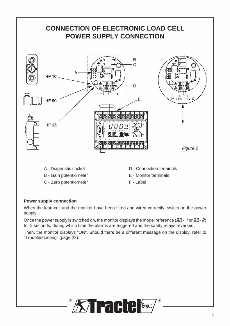
CONNECTION OF ELECTRONIC LOAD CELLPOWER SUPPLY CONNECTION
A - Diagnostic socket D - Connection terminals
B - Gain potentiometer E - Monitor terminals
C - Zero potentiometer F - Label
Power supply connection
When the load cell and the monitor have been fitted and wired correctly, switch on the powersupply.
Once the power supply is switched on, the monitor displays the model reference ( or )for 2 seconds, during which time the alarms are triggered and the safety relays reversed.
Then, the monitor displays "ON". Should there be a different message on the display, refer to"Troubleshooting" (page 22).
Figure 2

®
®
6
TEST FUNCTION
Display the signal from the load cell
Press the button to view the frequency signal from the load cell at that moment. Press the buttonagain to return to normal display . By default, the display returns to normal after 4 minutes.
Overload simulation
Press the button and hold it depressed, to simulate the overload condition. The display shows. The two relays are reversed and the alarms triggered. Release the button to end the test.
appears on the display. The two relays are reset and the alarms stop.
Display the parameters held in memoryPress the buttons and simultaneously.The monitor will display the messages in sequence :
Display Comments
1 Title of sequence
2 Test of all digits
3 Identification number of ………
4 N° …………… of the lifting device
5 Intermediate trip point
6 Value of this trip point (5) in weigh units (set by default)
7 Safety trip point
8 Value of this trip point (7) in weigh units (set by default)
9 End of sequence
Display of the version of softwarePress the button E to display the version of software (e.g. : 3.11)
Display the serial numberPress the buttons E and simultaneously to display the serial number (e.g. : 662).
®
®
7
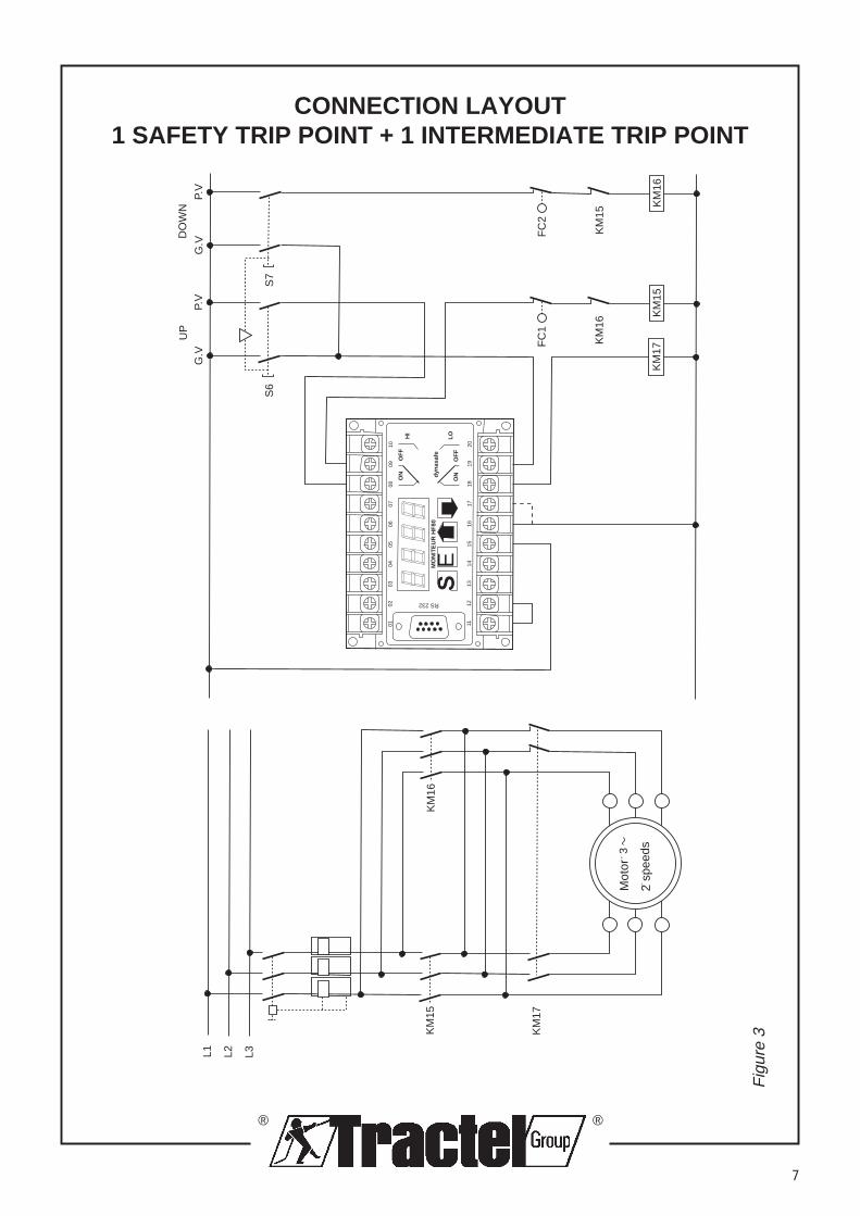
CONNECTION LAYOUT1 SAFETY TRIP POINT + 1 INTERMEDIATE TRIP POINT
Fig
ure
3
0201
0304
0506
0708
0910
1211
1314
1516
1718
1920
SSE
RS 232
OF
FO
N
OF
FO
N
HI
LO
MO
NIT
EU
R H
F80
dyna
safe
FC
1
KM
16
KM
15K
M17
S6
G.V
P.V
S7
G.V
P.V
FC
2
KM
15
KM
16
KM
17
L1 L2 L3
KM
15K
M16
2 vi
tess
es
Mot
eur
3
UP
DO
WN
Mot
or
2 sp
eeds

®
®
8
CONNECTION LAYOUT1 SAFETY TRIP POINT + 1 SLACK W.ROPE TRIP POINT
Fig
ure
4
0201
0304
0506
0708
0910
1211
1314
1516
1718
1920
SSE
RS 232
OF
FO
N
OF
FO
N
HI
LO
MO
NIT
EU
R H
F80
dyna
safe
FC
1
KM
16
KM
15K
M17
S6
G.V
P.V
S7
G.V
P.V
FC
2
KM
15
KM
16
KM
17
L1 L2 L3
KM
15K
M16
2 vi
tess
es
Mot
eur
3
UP
DO
WN
Mot
or
2 sp
eeds

®
®
9
GRAPHIC REPRESENTATION OF A LOADING CYCLE
HY
S S
-LO
(rE
L -
LO)
HY
S S
-LO
(rE
L -
HI)
HY
S S
-HI
HI-
HI
S-H
I
S-L
O
TE
MP
S
CHARGE
FREQUENCE
SP
EE
D
140
Val
eur
ondu
lato
ire
Val
eur
réel
le (
moy
enne
cal
culé
e pa
r m
icro
proc
esse
ur)
The frequency signal received by the monitor is directly proportional to the value of the load.
Fig
ure
5
TIM
E
undu
lato
ry v
alue
actu
al v
alue
(av
erag
e ca
lcul
ated
by
mic
ropr
oces
sor
FREQUENCY
LOAD

®
®
10
S-HI = Safety trip point
- Value of signal in Hertz (Hz).- Its value is generally set at 110% of the
nominal capacity of the lifting system, but itmay be adjusted to any point within thenominal capacity.
- It takes account of the real value of the loadand not the undulatory value.
- It sets off the safety and alarm systems atthe precise moment when the real value ofthe load exceeds the trip point.
HI-HI = Final safety trip point
- Value of signal in Hertz (Hz).
- By default, its value is set at 130% of thenominal capacity. This value can be adjustedto a different level as required.
- It takes account of the undulatory value ofthe load and not the real value.
- It sets off the safety and alarm systems atthe precise moment when the undulatoryvalue of the load exceeds the trip point.
S-LO = Intermediate trip point
- Value of signal in Hertz (Hz).
- Optional trip point : if it is not used it setsitself automatically at the same point as S-HI.
- Its value may be set at any level between Oand the S-HI trip point.
- It takes account of the real value of the loadand not the undulatory value.
- It sets off the safety and alarm systems onthe LO relay at the precise moment whenthe real value of the load :• exceeds the trip point, when in configuration
"HI" (see page 11).• falls below the trip point, when in
configuration "LO" (see page 11).
HYS S-HI & HYS S-LO (rEL-HI) = Hysteresis
- The value, in Hz, by which it is necessary toreduce the loading to reset the trip pointsafter they have been activated.
DEFINITIONS AND ABBREVIATIONS
HYS S-LO (rEL-LO) = Hysteresis
- The value, in Hz, by which it is necessary toincrease the loading to reset the trip pointsafter they have been activated (function :slack wire rope).
rEL-LO & rEL-HI = Configuration of theintermediate trip point
- The intermediate trip point S-LO may be setup in two ways :• rEL-HI : the relay is operated at the moment
when the real value of the load exceedsthe trip point. In this case, the trip pointserves as an intermediate trip point. Forexample : not possible to use the fastspeed functions where the load handledexceeds a certain value.
• rEL-LO : the relay is operated at themoment when the real value of the loadfalls below the trip point. In this case, thetrip point serves as a "slack wire rope"detector. For example, when using a liftingaccessory such as a spreader bar or specialclamps, it is possible to automatically stoplowering at the moment when theaccessory touches the ground. In this way,we may avoid problems with the wire ropeguiding when coming off the winch drum.
SPED - Speed of calculation
- By default, the value is set at 20, on anarbitrary scale of 1 to 40 (40 : slow; 1 : fast).
- Calculation of the real value of the loadcompared to its undulatory value may becarried out from a greater or lesser figure.The greater the sampling the more complexand precise the calculation. On the otherhand, the reaction time of the relays will belonger.

®
®
11
ADJUSTMENTS AND/OR MANUAL CORRECTIONOF PARAMETERS OF MONITOR HF80/1 - SET UP N°1
Fig
ure
60201
0304
0506
0708
0910
1211
1314
1516
1718
1920
SSE
RS 232
OF
FO
N
OF
FO
N
HI
LO
ESS
E SS
SS
EE
EE
SS
EE
SS
EE
EE
EE
EESS
EESS
ESS
ESSSS
(pro
cédu
re d
'acc
ès)
(5 s
econ
des)
HI o
u LO
de 1
à 4
0V
aleu
rs e
n fr
éque
nce
(val
eurs
par
déf
aut)
Util
iser
les
bout
ons
pour
mod
ifier
les
cons
igne
sP
aram
ètre
s pa
r dé
faut
Par
amet
ers
men
u
•O
nce
the
acce
ss p
roce
dure
has
bee
nco
mpl
eted
, the
ope
rato
r gai
ns a
cces
sto
the
par
amet
er a
nd/o
r co
rrec
tion
men
u.
•M
ove
with
in t
he m
enu
to a
lter
the
vario
us p
aram
eter
s us
ing
the
soft-
touc
h pu
sh-b
utto
ns o
n th
e fr
ont o
f the
mon
itor.
=M
ove
to th
e rig
ht, o
rR
educ
e a
valu
e.
=M
ove
to th
e le
ft, o
rIn
crea
se a
val
ue.
E =
Mov
e do
wnw
ards
, or
Con
firm
a v
alue
.
SS =
Mov
e up
war
ds, o
rE
xit w
ithou
t con
firm
ing
the
new
valu
e.
pres
s to
set
acc
ess
code
Fre
quen
cy v
alue
(ex
ampl
es)
HI o
r LO
from
1 to
40
Use
the
butto
ns to
alte
r th
e va
lues
Def
ault
para
met
ers

®
®
12
AUTOMATIC SETTING OF SAFETY TRIP POINTFOR MONITOR HF 80/1
SET-UP N° 2
Essential conditions : The load cell and the monitor should be correctly mounted and wired.
The hook of the lifting system should be free of any load.
The test operation should have been successfully carried out
(see page 6.
The relay (rEL) is set by default in "HI" (see page 11).(If necessary, check through Set-up n°1).
Equipment required : A load equivalent to 100% of the working load limit of the lifting system.
DISPLAY ACTION EXPLANATION
1 ON or LO SS E Display in normal operation.(push-buttons) Hook with no load.
2 ON orLO SS E Press buttons SS and E simultaneously for 5 seconds toaccess the menu for automatic setting of the trip point.
3 CODE (auto : Monitor ready for entering the access code.automatic display) "CODE" appears automatically.
4 1 Press to enter the code 2345 ( to correct)
5 2345 E Confirm the code by pressing E .
6 SEt.2 (auto) Set-up N° 2 : Automatic setting of the trip points.
7 N°.. (auto) N° of the lifting system.
8 …6 Use the arrows to enter the N° of the lifting system.
9 …6 E Confirm the N° by pressing E .
10 nUL. (auto) Zero.The frequency signal from the load cell will be considered aszero (no load).
11 nUL. E Confirm the zero by pressing E .
12 --- (auto) The four lines are displayed whilst the microprocessorcalculates the real value of the load.
13 750 (auto) Display in Hertz of the system zero. The example shows 750 Hz.
14 S-LO (auto) Intermediate trip point which will not be used on this systemsetting.As a result, the relays HI (terminals 08, 09,10) and LO(terminals 18, 19, 20) will trip simultaneously.
15 S-LO SS Press button SS to skip to setting the HI trip point.

®
®
13
16 S-HI (auto) Safety trip point S-HI (see page 10).
17 S-HI (auto) Lift a load equivalent to the maximum capacity of the liftingsystem by about 10 cm (or the maximum permitted load).
18 S-HI E When the load is stable, confirm the trip point by pressingbutton E .
19 ---- (auto) The microprocessor calculates the real value of the load.
20 6750 (auto) Display in Hertz of the upper trip point (S-HI). The exampleshows 6750 Hz. The microprocessor calculates this trippoint to set it at 110% of the load lifted. The final upper trippoint HI-HI is automatically calculated and set at 30% overthe safety trip point (S-HI).
21 End (auto) End of automatic setting procedure.
22 ON (auto) The monitor returns to normal operation.
NOTE : After using the automatic setting procedure using SET-UP N°2, the user has the option of modifying allthe trip points and/or the system parameters by using the SET-Up N°1 procedure. (see page 11)
AUTOMATIC SETTING OF SAFETY TRIP POINTAND INTERMEDIATE TRIP POINT
FOR MONITOR HF 80/1SET-UP N° 2
Essential conditions : The load cell and the monitor should be correctly mounted and
wired.
The hook of the lifting system should be free of any load.
The test operation should have been successfully carried out
(see page 6).
The relay (rEL) is set by default in "HI" (see page 11).(If necessary, check through SET-UP N°1).
Equipment required : A load (load N°1) equivalent to the value of the intermediate trippoint, S-LO.
A load (load N°2) equivalent to 100% of the working load limit ofthe lifting system.
DISPLAY ACTION EXPLANATION
1 ON SS E Display in normal operation. Hook with no load.(push-buttons)
2 ON SS E Press buttons SS and E simultaneously for 5 seconds(5 sec) to access the menu for automatic setting of the trip points.

®
®
14
3 CODE (auto : Monitor ready for entering the access code.automatic display) "CODE" is displayed automatically.
4 1 Press to enter the code 2345 ( to correct).
5 2345 E Confirm the code by pressing E .
6 SEt.2 (auto) Set-up N° 2 : Automatic setting of the trip points.
7 N°.. (auto) N° of the lifting system.
8 ...6 Use the arrows to enter the N° of the lifting system.
9 …6 E Confirm the N° by pressing E .
10 nUL (auto) Zero.The frequency signal from the load cell will be consideredas zero (no load).
11 nUL. E Confirm the zero by pressing E .
12 ---- (auto) The four lines are displayed whilst the microprocessorcalculates the real value of the load.
13 750 (auto) Display in Hertz of the system zero. The example shows750 Hz.
14 S-LO (auto) Intermediate trip point (S-LO).
15 S-LO (auto) Lift load N°1 about 10 cm.
16 S-LO E When the load is stable, confirm the trip point by pressingbutton E .
17 ---- (auto) The microprocessor calculates the real value of the load.
18 2750 (auto) Display in Hertz of the intermediate trip point S-LO . Theexample shows 2750 Hz.
19 S-Hi (auto) Safety trip point S-HI (see age 10).
20 S-Hi (auto) Lower the load N°1. Lift load N°2 about 10 cm.note: Up to 4 minutes is allowed to carry out this operation, afterwhich time the monitor returns to normal operation and the set upmust restart at point 1.
21 S-HI E When the load is stable, confirm the trip point by pressingbutton E .
22 ---- (auto) The monitor calculates the real value of the load.
23 6750 (auto) Display in Hertz of the upper trip point (S-HI). The exampleshows 6750 Hz. The microprocessor calculates this trippoint to set it at 110% of the load lifted. The final upper trippoint HI-HI is automatically calculated and set at 130% overthe safety trip point (S-HI).
24 End (auto) End of automatic setting procedure.
25 LO (auto) The monitor returns to normal operation. It displays LOsince load N°2 is in excess of the S-LO trip point and it isstill suspended on the hook.Lower the load so that there isno load on the hook. The monitor will display ON
note : After using the automatic setting procedure using SET-UP N°2,the user has the option of modifying all the trip points and/or thesystem parameters by using the SET-UP N°1 procedure.(see page11).
®
®
15
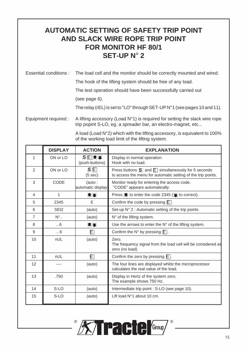
AUTOMATIC SETTING OF SAFETY TRIP POINTAND SLACK WIRE ROPE TRIP POINT
FOR MONITOR HF 80/1SET-UP N° 2
Essential conditions : The load cell and the monitor should be correctly mounted and wired.
The hook of the lifting system should be free of any load.
The test operation should have been successfully carried out
(see page 6).
The relay (rEL) is set to "LO" through SET-UP N°1 (see pages 10 and 11).
Equipment required : A lifting accessory (Load N°1) is required for setting the slack wire ropetrip popint S-LO, eg. a spreader bar, an electro-magnet, etc...
A load (Load N°2) which with the lifting accessory, is equivalent to 100%of the working load limit of the lifting system.
DISPLAY ACTION EXPLANATION
1 ON or LO SS E Display in normal operation.(push-buttons) Hook with no load.
2 ON or LO SS E Press buttons SS and E simultaneously for 5 seconds(5 sec) to access the menu for automatic setting of the trip points.
3 CODE (auto : Monitor ready for entering the access code.automatic display) "CODE" appears automatically.
4 1 Press to enter the code 2345 ( to correct).
5 2345 E Confirm the code by pressing E .
6 SEt2 (auto) Set-up N° 2 : Automatic setting of the trip points.
7 N°.. (auto) N° of the lifting system.
8 ...6 Use the arrows to enter the N° of the lifting system.
9 …6 E Confirm the N° by pressing E .
10 nUL (auto) Zero.The frequency signal from the load cell will be considered aszero (no load).
11 nUL E Confirm the zero by pressing E .
12 ---- (auto) The four lines are displayed whilst the microprocessorcalculates the real value of the load.
13 .750 (auto) Display in Hertz of the system zero.The example shows 750 Hz.
14 S-LO (auto) Intermediate trip point : S-LO (see page 10).
15 S-LO (auto) Lift load N°1 about 10 cm.

®
®
16
16 S-LO E When the load is stable, confirm the trip point by pressingbutton E .
17 ---- (auto) The microprocessor calculates the real value of the load.
18 2750 (auto) Display in Hertz of the intermediate trip point S-LO. Theexample shows 2750 Hz.
19 S-HI (auto) Safety trip point S-HI (see page 10).
20 S-HI (auto) Using the lifting accessory which represents load N°1, liftload N°2 about 10 cm.note : Up to 4 minutes is allowed to carry out this operation, afterwhich time the monitor returns to normal operation and the set-upmust restart at point 1.
21 S-HI E When the load is stable, confirm the trip point by pressingbutton E .
22 ---- (auto) The microprocessor calculates the real value of the load.
23 6750 (auto) Display in Hertz of the upper trip point (S-HI). The exampleshows 6750 Hz. The microprocessor calculates this trippoint to set it at 110% of the load lifted. The final upper trippoint HI-HI is automatically calculated and set at 130% overthe safety trip point (S-HI).
24 End. (auto) End of automatic setting procedure.
25 ON (auto) The monitor returns to normal operation. It displays ONwhilst the suspended load is between trip points S-HI and S-LO (slack wire rope).
26 LO (auto) The monitor will display LO and switch the S-LO relay(stopping the lowering operation) as soon as the liftingaccessory, on touching the ground, causes the signal fromthe load cell to fall below the S-LO trip point for slack wirerope. To adjust the hysteresis see pages 10 and 11.
NOTE : After using the automatic setting procedure using SET-UP N°2, the user has the option of modifying allthe trip points and/or the system parameters by using the SET-UP N°1 procedure (see page 11).
®
®
17
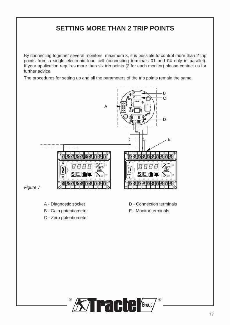
SETTING MORE THAN 2 TRIP POINTS
By connecting together several monitors, maximum 3, it is possible to control more than 2 trippoints from a single electronic load cell (connecting terminals 01 and 04 only in parallel).If your application requires more than six trip points (2 for each monitor) please contact us forfurther advice.
The procedures for setting up and all the parameters of the trip points remain the same.
A
CB
D
E
0201 03 04 05 06 07 08 09 10
1211 13 14 15 16 17 18 19 20
SS E
RS
232
OFFON
OFFON
HI
LO
MONITEUR HF80 dynasafe
0201 03 04 05 06 07 08 09 10
1211 13 14 15 16 17 18 19 20
SS E
RS
232
OFFON
OFFON
HI
LO
MONITEUR HF80 dynasafe
A - Diagnostic socket D - Connection terminals
B - Gain potentiometer E - Monitor terminals
C - Zero potentiometer
Figure 7
®
®
18
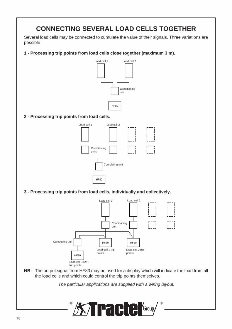
CONNECTING SEVERAL LOAD CELLS TOGETHERSeveral load cells may be connected to cumulate the value of their signals. Three variations arepossible :
1 - Processing trip points from load cells close together (maximum 3 m).
Capteur 1 Capteur 2
HF80
Conditionneur
2 - Processing trip points from load cells.
Capteur 1 Capteur 2
HF80Sommateur
Conditionneurs
HF80
3 - Processing trip points from load cells, individually and collectively.
Capteur 1 Capteur 2
Seuils capteur 1 Seuils capteur 2
Sommateur
Conditionneurs
HF80
HF80 HF80
Seuils capteur 1+ 2 + …
NB : The output signal from HF83 may be used for a display which will indicate the load from allthe load cells and which could control the trip points themselves.
The particular applications are supplied with a wiring layout.
Load cell 2
Conditioningunit
Load cell 1
Load cell 1 Load cell 2
Cumulating unit
Conditioningunits
Load cell 1 Load cell 2
Conditioningunit
Cumulating unit
Load cell 1 trippoints
Load cell 2 trippoints
Load cell 1+2+..trip points

®
®
19
ADJUSTMENT OF ZERO AND GAIN POTENTIOMETERSin the electronics of load cells or controls
General information :
• The conditioning units incorporated in the load cells are factory set to give an output of 7000 Hzwhen the relevant load cell is subjected to its nominal capacity. For a no load condition, the signalis 500 Hz. A frequencey of less than 400 Hz is considered as an operating fault (ER20) (see page22).
• As a result of sheaving or the capacity of the lifting system, the load cell may be used for a partof its nominal capacity, for example 50%. In this case the output frequency will only be 3500 Hz(ie 7000 Hz/2). The effective resolution of the system will be 3000 Hz (ie 3500 Hz - 500 Hz).
• For reasons of sensitivity, particularly when displaying the load applied, it is sometimes usefulto have a greater resolution. This can be achieved by increasing the "gain".
Figure 8
MONITEUR
CAPTEUR
����
BC
F
E
A
D
Monitor
LoadcellA - Diagnostic socket
B - Gain potentiometer
C - Zero potentiometer
D - Connection terminals from load cell outputto conditioning unit
E- Connection terminals from conditioningunit output to monitor
F - Connection terminals from load cell inputto conditioning unit

®
®
20
ADJUSTMENT OF ZERO AND GAIN POTENTIOMETERSin the electronics of load cells or controls
Essential conditions : The hook of the lifting system should be free of any load.
The test operation should have been successfully carried out.
Set the display to show the frequency (press button )
Equipment required : A load (denoted "Pm") equivalent to 100% of the working loadlimit of the lifting system.
DISPLAY ACTION EXPLANATION
1 650 Frequency signal from the load cell at rest (our example).
2 650 Reset to zero Using the "Zero" potentiometer reduce the value of thefrequency displayed to between 1 and 5 Hz.
3 ..1
4 Lift the load"Pm" by 10 cm
5 2500 Frequency signal from the load cell under the effect of theload lifted (our example : 2500).
6 7000 Adjust the "Gain" Increase the gain until the maximum value is displayedpotentiometer (anti-clockwise direction)
Turn 3 times in clockwise direction.• If the display shows a value greater than 7000 Hz,continue to turn until 7000 Hz is reached• If the display shows a value of less than 7000 Hz, leave it at this position.
7 Lower the laod
8 ..27 Frequency signal from the load cell at rest (our example 27).
9 .500 Adjust the "Zero" Using the "Zezro" potentiometer, increase the value of thesignal to 500Hz.
End of adjustment procedure.The user may now set the system parameters of the monitor by using SET-UP N°1 and N°2 procedures.
®
®
21
MESSAGES
DISPLAY EXPLANATION
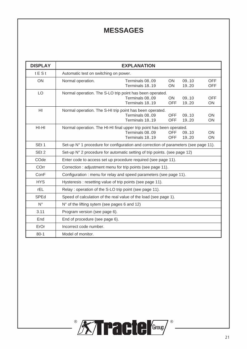
t E S t Automatic test on switching on power.
ON Normal operation. Terminals 08..09 ON 09..10 OFFTerminals 18..19 ON 19..20 OFF
LO Normal operation. The S-LO trip point has been operated.Terminals 08..09 ON 09..10 OFFTerminals 18..19 OFF 19..20 ON
HI Normal operation. The S-HI trip point has been operated.Terminals 08..09 OFF 09..10 ONTerminals 18..19 OFF 19..20 ON
HI-HI Normal operation. The HI-HI final upper trip point has been operated.Terminals 08..09 OFF 09..10 ONTerminals 18..19 OFF 19..20 ON
SEt 1 Set-up N° 1 procedure for configuration and correction of parameters (see page 11).
SEt 2 Set-up N° 2 procedure for automatic setting of trip points. (see page 12)
COde Enter code to access set up procedure required (see page 11).
COrr Correction : adjustment menu for trip points (see page 11).
ConF Configuration : menu for relay and speed parameters (see page 11).
HYS Hysteresis : resetting value of trip points (see page 11).
rEL Relay : operation of the S-LO trip point (see page 11).
SPEd Speed of calculation of the real value of the load (see page 1).
N° N° of the lifting sytem (see pages 6 and 12)
3.11 Program version (see page 6).
End End of procedure (see page 6).
ErOr Incorrect code number.
80-1 Model of monitor.

®
®
22
TROUBLESHOOTING
DISPLAY CAUSE REMEDY
ER.20 The frequency signal from the loadcell is less than 400 Hz.
1) Signal between 1 and 399 Hz.
2) Signal = 0 Hz- Wiring fault- Faulty power supply- Faulty monitor- Faulty load cell
NOTE : An inversion of the polarityof the power supply to the load cellcould cause permanent damage toseveral electronic components.
The frequency signal from the loadcell cannot be processed by themonitor.The signal is over 9999 Hz.
- The load cell is being operatedbeyond its capacity.
- Faulty monitor.- Faulty load cell.
NOTE : An inversion of the polarityof the power supply to the load cellcould cause permanent damage toseveral electronic components.
To display the frequency from the loadcell, press the Down button .
1) Increase the frequency value over500 Hz by adjusting thepotentiometer for "Zero". For this,follow the instructions on pages 19and 20 "Adjustment of zero andgain potentiometers".
2) - Check the wiring- Check the power supply- Refer to After Sales Service- Refer to After Sales Service
- Check the capacity and therequirement for the application.
- Refer to After Sales Service.- Refer to After Sales Service.
ER.21
®
®
23
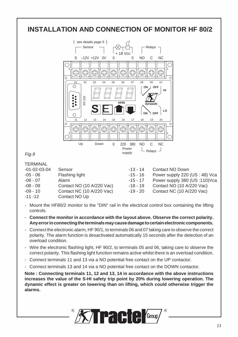
INSTALLATION AND CONNECTION OF MONITOR HF 80/2
0201 03 04 05 06 07 08 09 10
1211 13 14 15 16 17 18 19 20
SS E
RS
232
OFFON
OFFON
HI
LO
0 220 380 NO C NC
Alimentation Vca Relais
0+ 18 Vcc
0 NO C NC
RelaisCapteur
S –12V +12V 0V
(voir détails page 5)
MONITEUR HF80 dynasafe
Montée Descente
Entrées compteursFig.9
TERMINAL-01-02-03-04 Sensor -13 - 14 Contact NO Down-05 - 06 Flashing light -15 - 16 Power supply 220 (US : 48) Vca-06 - 07 Alarm -15 - 17 Power supply 380 (US :110)Vca-08 - 09 Contact NO (10 A/220 Vac) -18 - 19 Contact NO (10 A/220 Vac)-09 - 10 Contact NC (10 A/220 Vac) -19 - 20 Contact NC (10 A/220 Vac)-11 -12 Contact NO Up
- Mount the HF80/2 monitor to the "DIN" rail in the electrical control box containing the liftingcontrols.
- Connect the monitor in accordance with the layout above. Observe the correct polarity.Any error in connecting the terminals may cause damage to certain electronic components.
- Connect the electronic alarm, HF 90/1, to terminals 06 and 07 taking care to observe the correctpolarity. The alarm function is desactivated automatically 15 seconds after the detection of anoverload condition.
- Wire the electronic flashing light, HF 90/2, to terminals 05 and 06, taking care to observe thecorrect polarity. This flashing light function remains active whilst there is an overload condition.
- Connect terminals 11 and 13 via a NO potential free contact on the UP contactor.
- Connect terminals 13 and 14 via a NO potential free contact on the DOWN contactor.
Note : Connecting terminals 11, 12 and 13, 14 in accordance with the above instructionsincreases the value of the S-HI safety trip point by 20% during lowering operation. Thedynamic effect is greater on lowering than on lifting, which could otherwise trigger thealarms.
see details page 5
RelaysSensor
Powersupply
Up Down
Relays