intelligent behavior generation for autonomous...
TRANSCRIPT
Intelligent Behavior Generation for Autonomous Mobile Robots: Planning and Control
- CSOIS Autonomous Robotics Overview -
Kevin L. Moore, Director
Center for Self-Organizing and Intelligent SystemsUtah State University
Logan, Utah
February 2004

Outline• Background• ODIS – An ODV Robot for Physical Security• USU UGV Architecture (Computing Hardware and Sensors)• Mission Planning and Control System
− Multi-Resolution Approach− Epsilon-Controller
• Intelligent Behavior Generation− Delayed-Commitment Concept− MoRSE: a Grammar-Based Command Environment− Software Architecture
• Reaction via Feedback in the Planner• Conclusions
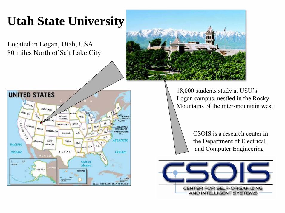
Utah State University
Located in Logan, Utah, USA80 miles North of Salt Lake City
18,000 students study at USU’sLogan campus, nestled in the Rocky Mountains of the inter-mountain west
CSOIS is a research center inthe Department of Electricaland Computer Engineering
CSOIS Core Capabilities and Expertise
• Center expertise is robotics, automation, control, and AI• Control System Engineering
– Algorithms (Intelligent Control)– Actuators and Sensors– Hardware and Software Implementation
• Intelligent Planning and Optimization• Real-Time Programming• Electronics Design and Implementation• Mechanical Engineering Design and Implementation• System Integration
We make real systems that WORK!

Center for Self-Organizing andIntelligent Systems
• Utah Center of Excellence graduate (formed in 1992)• Horizontally-integrated (multi-disciplinary)
– Electrical and Computer Engineering (Home dept.)– Mechanical Engineering– Computer Science
• Vertically-integrated staff (20-40) of faculty, postdocs, engineers, grad students and undergrads
• Average over $2.0M in funding per year since 1998• Three spin-off companies since 1994• Major commercialization in 2004• Primary focus on unmanned ground vehicles and control systems
CSOIS Projects• Since 1992: Approximately
– 15 automation and control projects– 15 robotics/autonomous vehicle projects– Funding from both private industry and government
• Current focus on vehicle automation and robotics
• Major US Army Tank-Automotive Command (TACOM) program, 1998-present
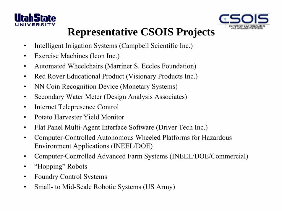
Representative CSOIS Projects• Intelligent Irrigation Systems (Campbell Scientific Inc.)• Exercise Machines (Icon Inc.)• Automated Wheelchairs (Marriner S. Eccles Foundation)• Red Rover Educational Product (Visionary Products Inc.)• NN Coin Recognition Device (Monetary Systems)• Secondary Water Meter (Design Analysis Associates)• Internet Telepresence Control• Potato Harvester Yield Monitor• Flat Panel Multi-Agent Interface Software (Driver Tech Inc.)• Computer-Controlled Autonomous Wheeled Platforms for Hazardous
Environment Applications (INEEL/DOE) • Computer-Controlled Advanced Farm Systems (INEEL/DOE/Commercial)• “Hopping” Robots• Foundry Control Systems• Small- to Mid-Scale Robotic Systems (US Army)
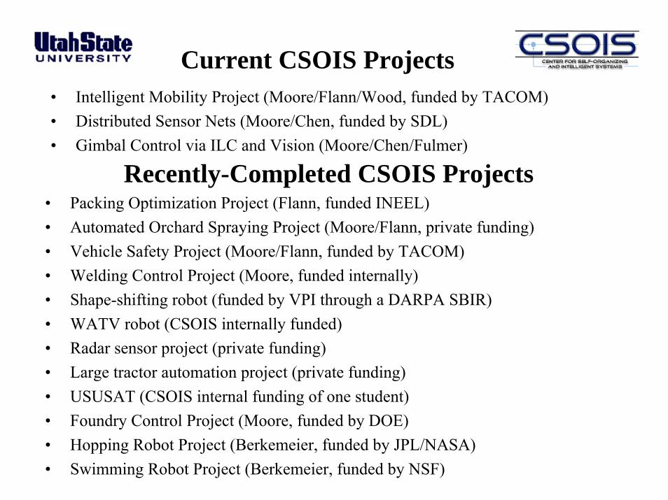
Current CSOIS Projects• Intelligent Mobility Project (Moore/Flann/Wood, funded by TACOM)• Distributed Sensor Nets (Moore/Chen, funded by SDL)• Gimbal Control via ILC and Vision (Moore/Chen/Fulmer)
Recently-Completed CSOIS Projects• Packing Optimization Project (Flann, funded INEEL)• Automated Orchard Spraying Project (Moore/Flann, private funding)• Vehicle Safety Project (Moore/Flann, funded by TACOM)• Welding Control Project (Moore, funded internally)• Shape-shifting robot (funded by VPI through a DARPA SBIR)• WATV robot (CSOIS internally funded)• Radar sensor project (private funding)• Large tractor automation project (private funding)• USUSAT (CSOIS internal funding of one student)• Foundry Control Project (Moore, funded by DOE)• Hopping Robot Project (Berkemeier, funded by JPL/NASA)• Swimming Robot Project (Berkemeier, funded by NSF)
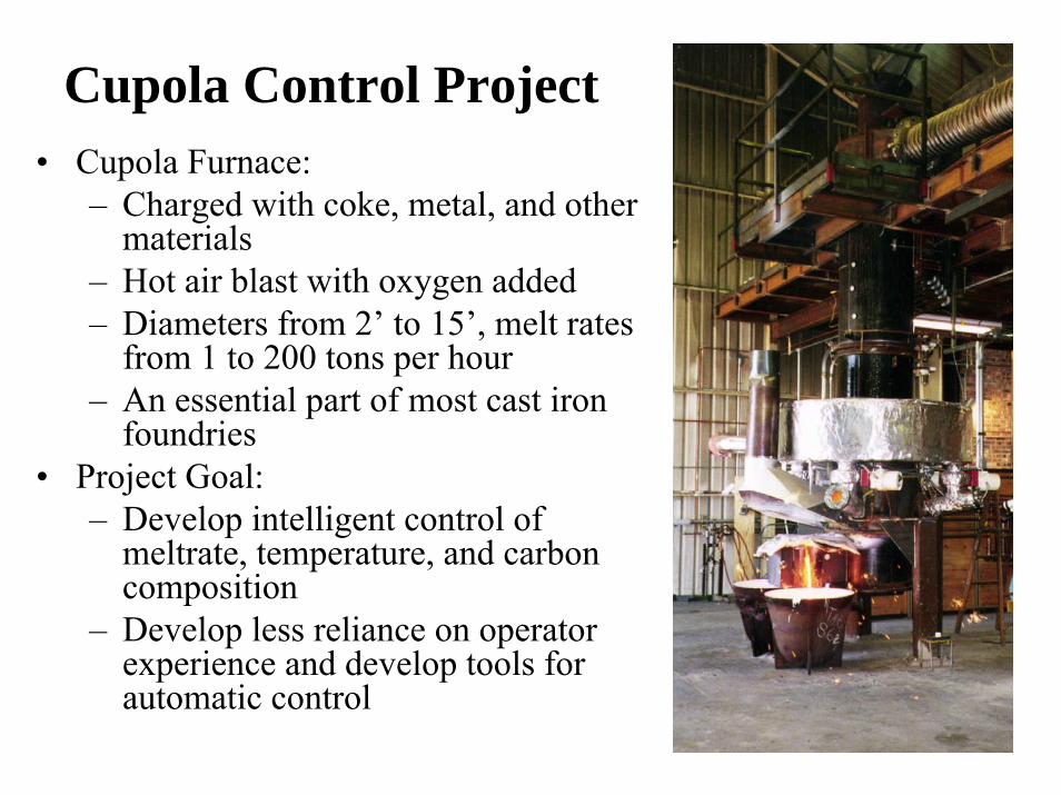
Cupola Control Project• Cupola Furnace:
– Charged with coke, metal, and other materials
– Hot air blast with oxygen added– Diameters from 2’ to 15’, melt rates
from 1 to 200 tons per hour– An essential part of most cast iron
foundries• Project Goal:
– Develop intelligent control of meltrate, temperature, and carbon composition
– Develop less reliance on operator experience and develop tools for automatic control

Welding Research
• Goal: achieve a “good” weld by controlling – Torch travel speed– Electrode wire speed– Torch height– Power supply
• Research led to a book
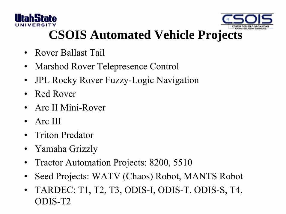
CSOIS Automated Vehicle Projects• Rover Ballast Tail• Marshod Rover Telepresence Control• JPL Rocky Rover Fuzzy-Logic Navigation• Red Rover• Arc II Mini-Rover• Arc III• Triton Predator• Yamaha Grizzly• Tractor Automation Projects: 8200, 5510• Seed Projects: WATV (Chaos) Robot, MANTS Robot• TARDEC: T1, T2, T3, ODIS-I, ODIS-T, ODIS-S, T4,
ODIS-T2
Center for Self-Organizing andIntelligent Systems
• Utah Center of Excellence graduate (formed in 1992)• Horizontally-integrated (multi-disciplinary)
– Electrical and Computer Engineering (Home dept.)– Mechanical Engineering– Computer Science
• Vertically-integrated staff (20-40) of faculty, postdocs, engineers, grad students and undergrads
• Average over $2.0M in funding per year since 1998• Three spin-off companies since 1994• Major commercialization in 2004• Primary focus on unmanned ground vehicles and control systems
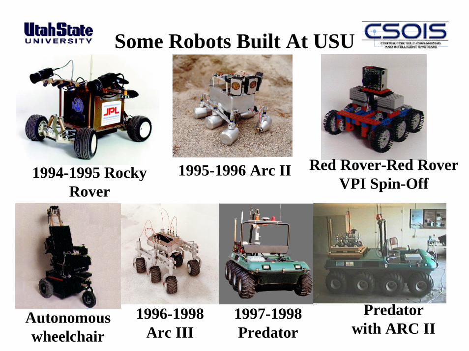
1995-1996 Arc II
1996-1998 Arc III
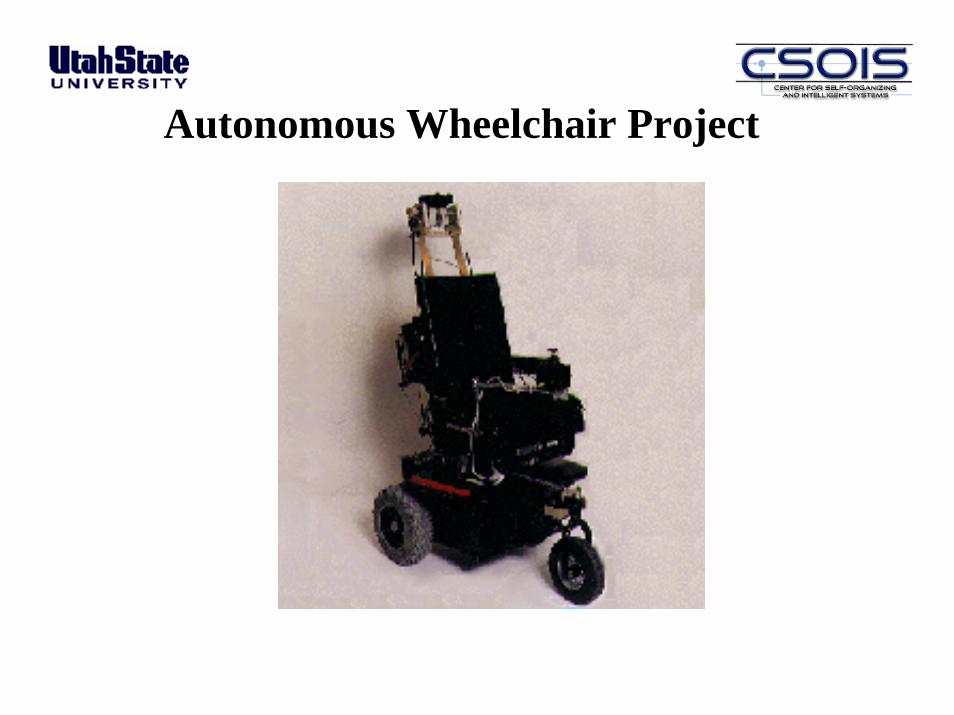
Autonomous wheelchair
1997-1998Predator
Predator with ARC II
1994-1995 Rocky Rover
Some Robots Built At USU
Red Rover-Red RoverVPI Spin-Off
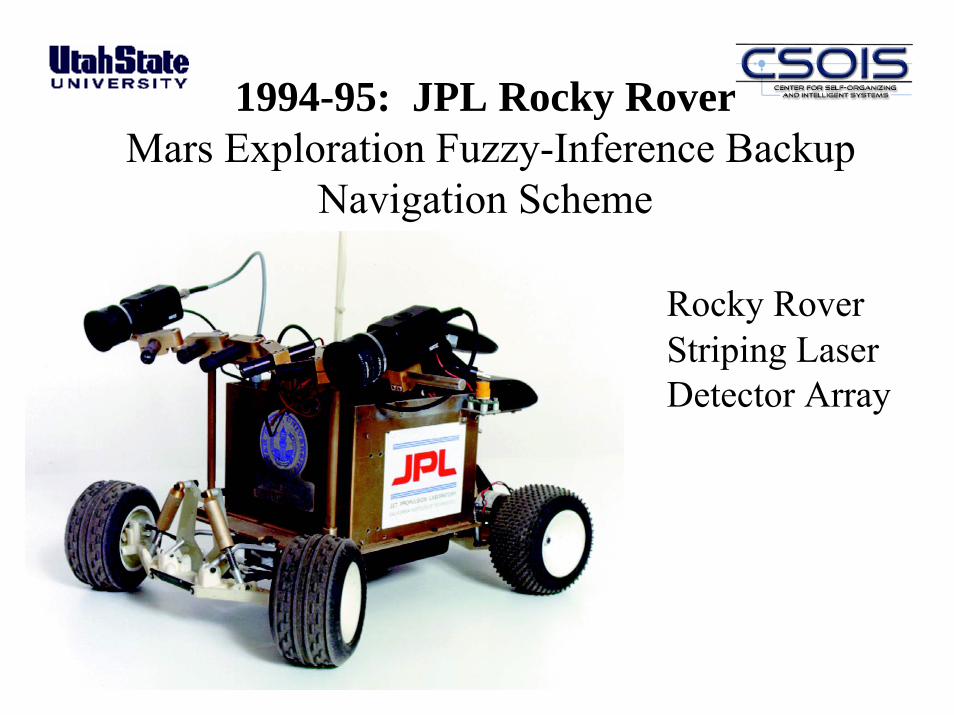
1994-95: JPL Rocky RoverMars Exploration Fuzzy-Inference Backup
Navigation Scheme
Rocky Rover Striping Laser Detector Array

Red Rover, Red RoverEducational Project - 1995
• Collaboration with Lego and The Planetary Society
• Produced by CSOIS spin-off company, VPI
• Students build Rover and Marscape
• Other students drive Rover over the internet
• 500-600 were sold
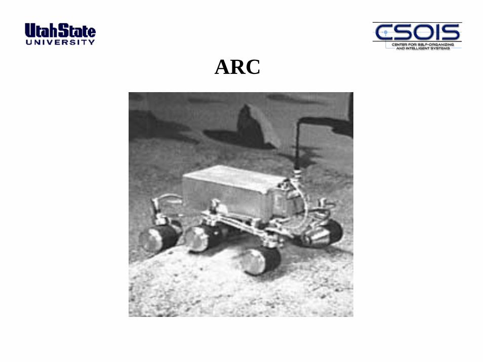
ARC

1995-96: ARC II Mini-RoverTest for navigation and control
• Passive suspension• Independent drive &
steering motors• In-wheel power• Distributed controls
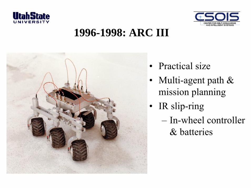
1996-1998: ARC III
• Practical size• Multi-agent path &
mission planning• IR slip-ring
– In-wheel controller & batteries
Autonomous Wheelchair Project
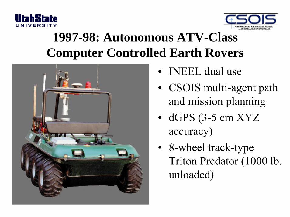
• INEEL dual use• CSOIS multi-agent path
and mission planning• dGPS (3-5 cm XYZ
accuracy)• 8-wheel track-type
Triton Predator (1000 lb. unloaded)
1997-98: Autonomous ATV-Class Computer Controlled Earth Rovers
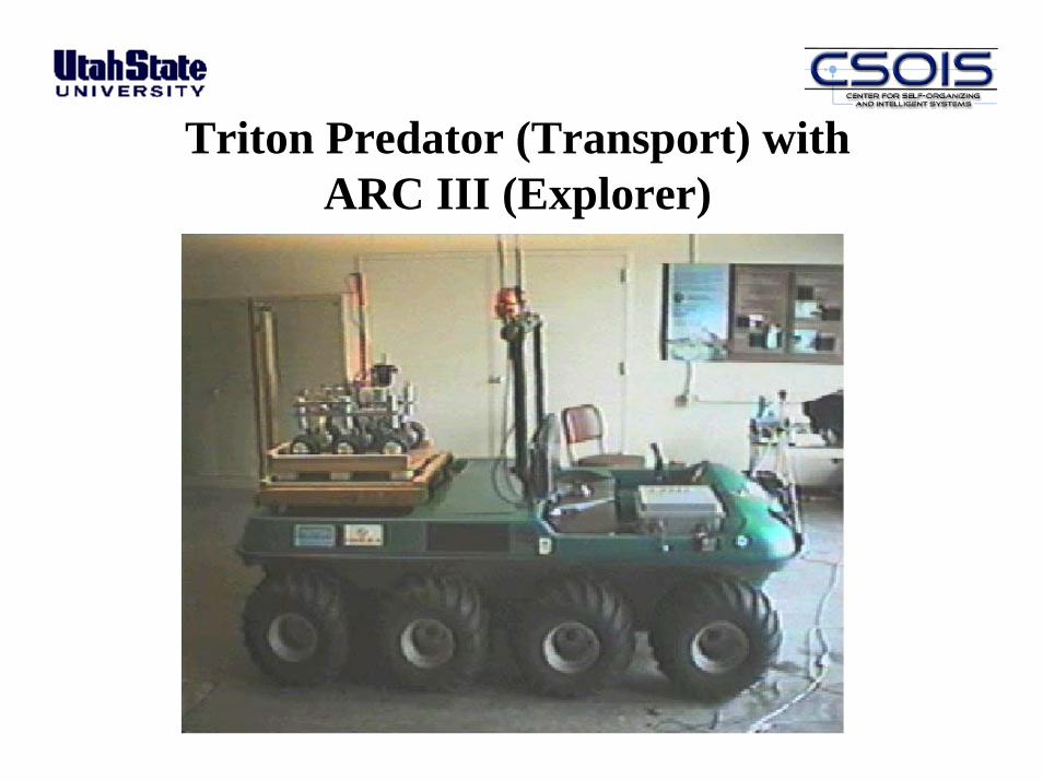
Triton Predator (Transport) with ARC III (Explorer)
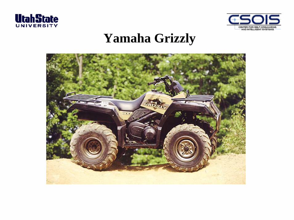
Yamaha Grizzly

Some More Robots Built At USU
T1 -1998 T2 -1998
ODIS I -2000
T3 -1999
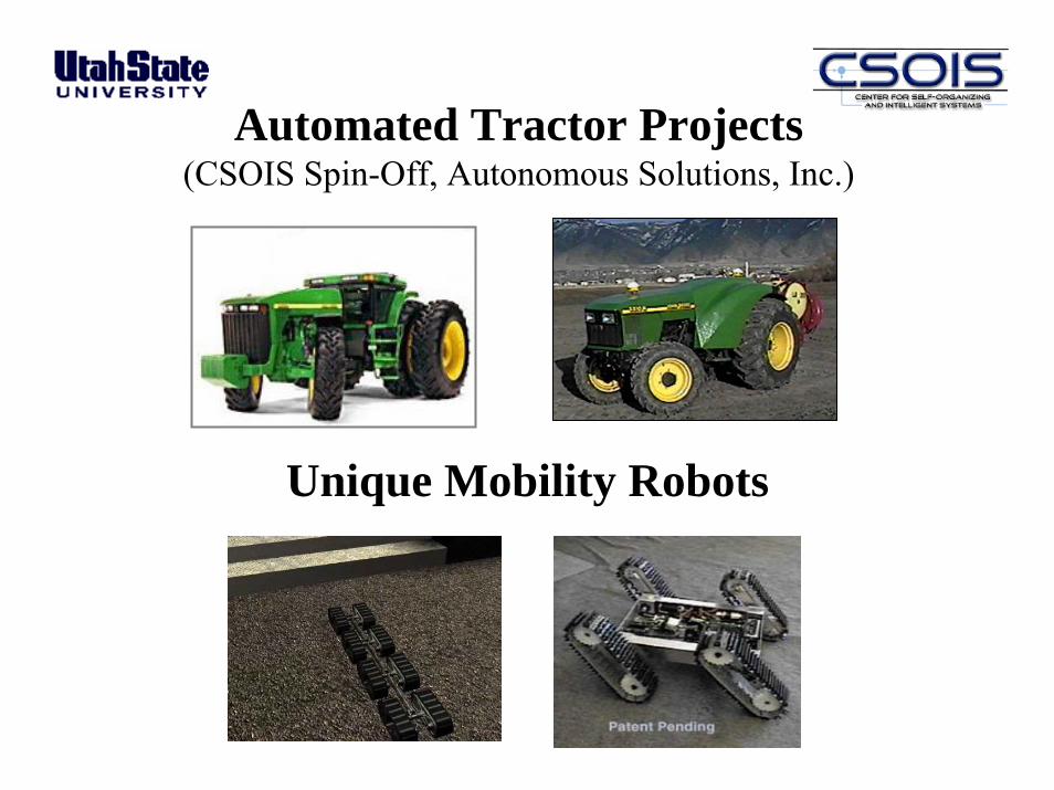
Automated Tractor Projects(CSOIS Spin-Off, Autonomous Solutions, Inc.)
Unique Mobility Robots

Automated Tractor Projects(CSOIS Spin-Off, Autonomous Solutions, Inc.)
JD 5510NJD 8200
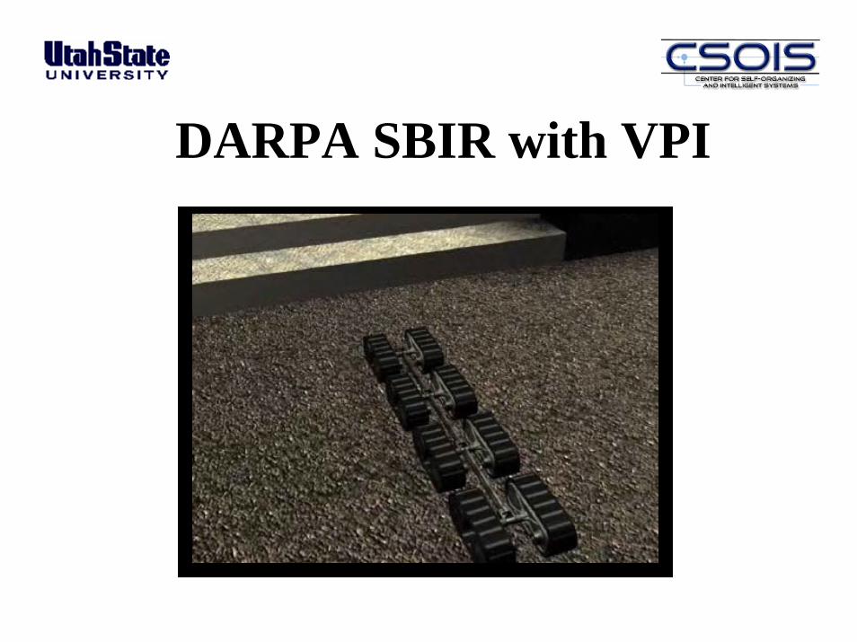
DARPA SBIR with VPI
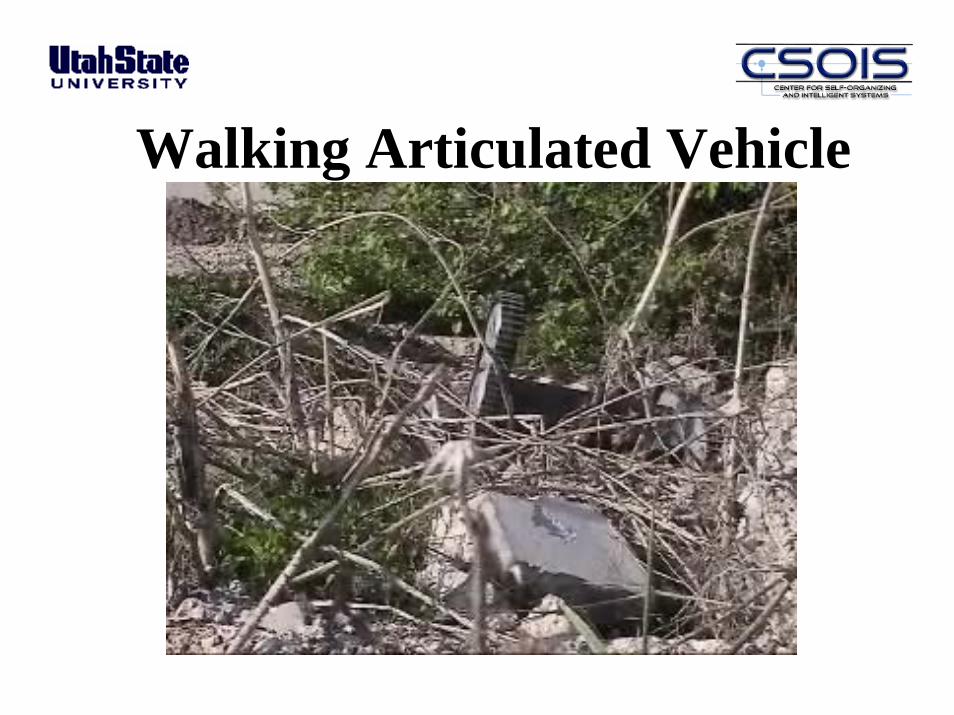
Walking Articulated Vehicle
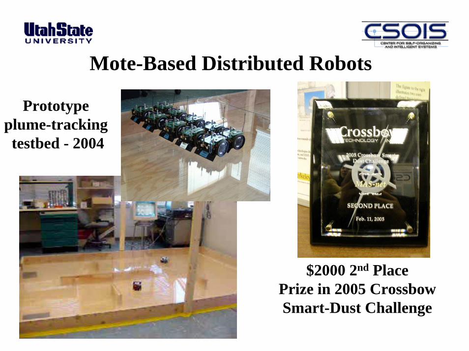
Mote-Based Distributed Robots
Prototype plume-tracking testbed - 2004
$2000 2nd PlacePrize in 2005 CrossbowSmart-Dust Challenge
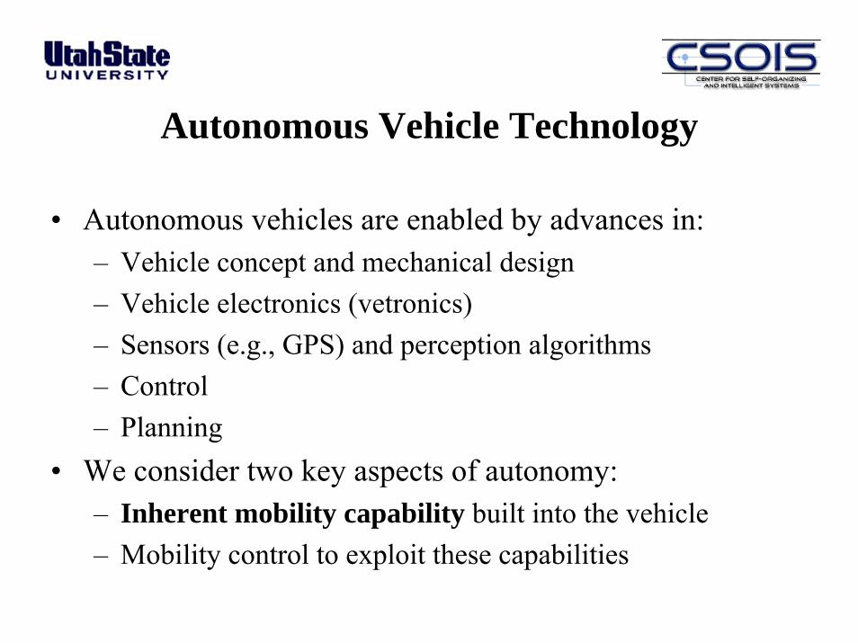
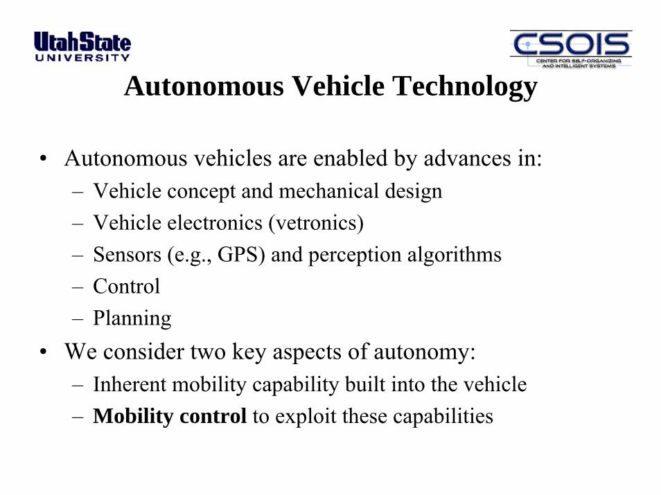
Autonomous Vehicle Technology
• Autonomous vehicles are enabled by advances in:– Vehicle concept and mechanical design– Vehicle electronics (vetronics)– Sensors (e.g., GPS) and perception algorithms– Control– Planning
• We consider two key aspects of autonomy:– Inherent mobility capability built into the vehicle– Mobility control to exploit these capabilities
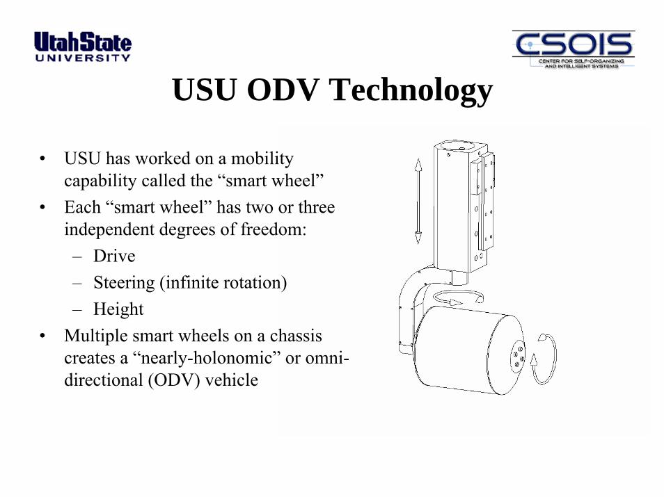
USU ODV Technology
• USU has worked on a mobility capability called the “smart wheel”
• Each “smart wheel” has two or three independent degrees of freedom:– Drive– Steering (infinite rotation)– Height
• Multiple smart wheels on a chassis creates a “nearly-holonomic” or omni-directional (ODV) vehicle
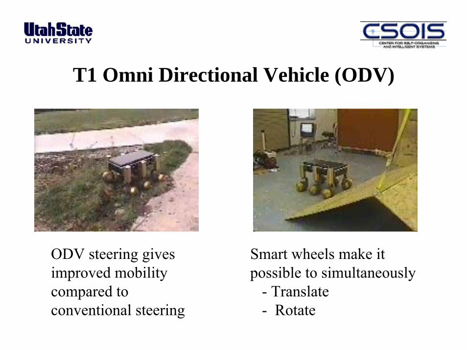
T1 Omni Directional Vehicle (ODV)
Smart wheels make itpossible to simultaneously
- Translate- Rotate
ODV steering gives improved mobility compared to conventional steering
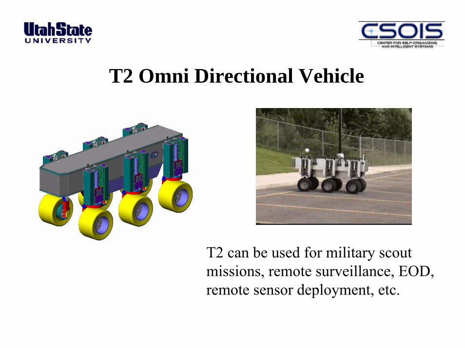
T2 Omni Directional Vehicle
T2 can be used for military scout missions, remote surveillance, EOD,remote sensor deployment, etc.
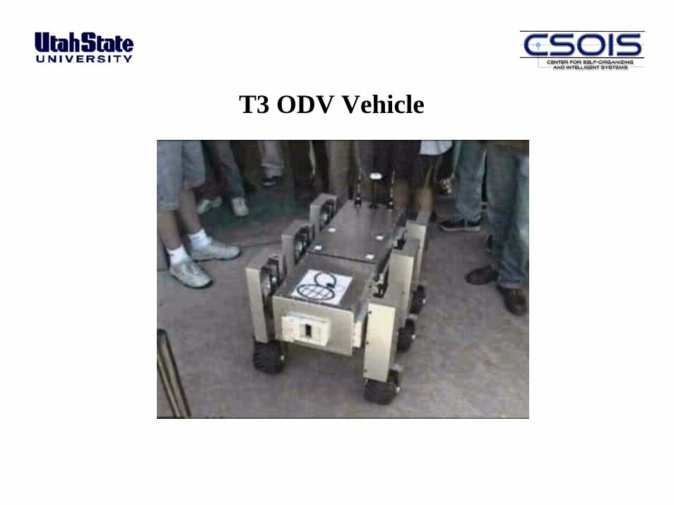
T3 ODV Vehicle
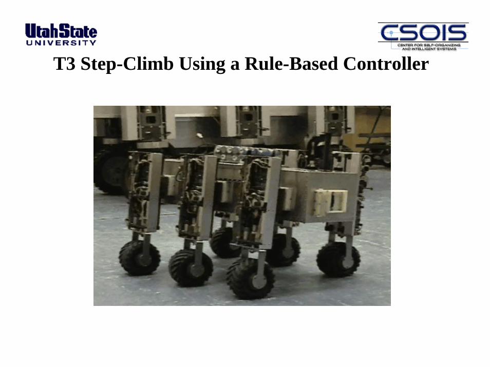
T3 Step-Climb Using a Rule-Based Controller
“Putting Robots in Harm’s WaySo People Aren’t”
An ODV Application: Physical Security
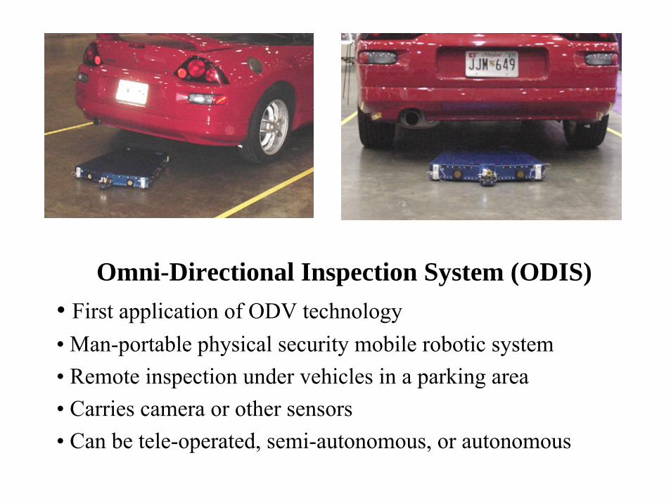
Omni-Directional Inspection System (ODIS)• First application of ODV technology• Man-portable physical security mobile robotic system• Remote inspection under vehicles in a parking area• Carries camera or other sensors • Can be tele-operated, semi-autonomous, or autonomous
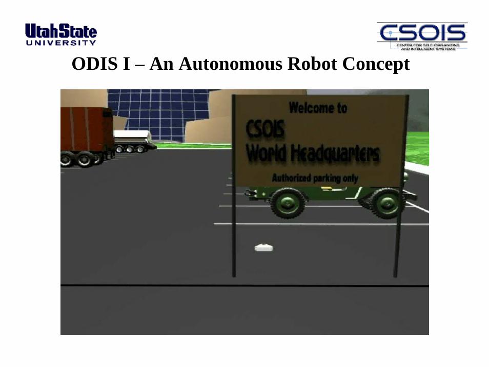
ODIS I – An Autonomous Robot Concept
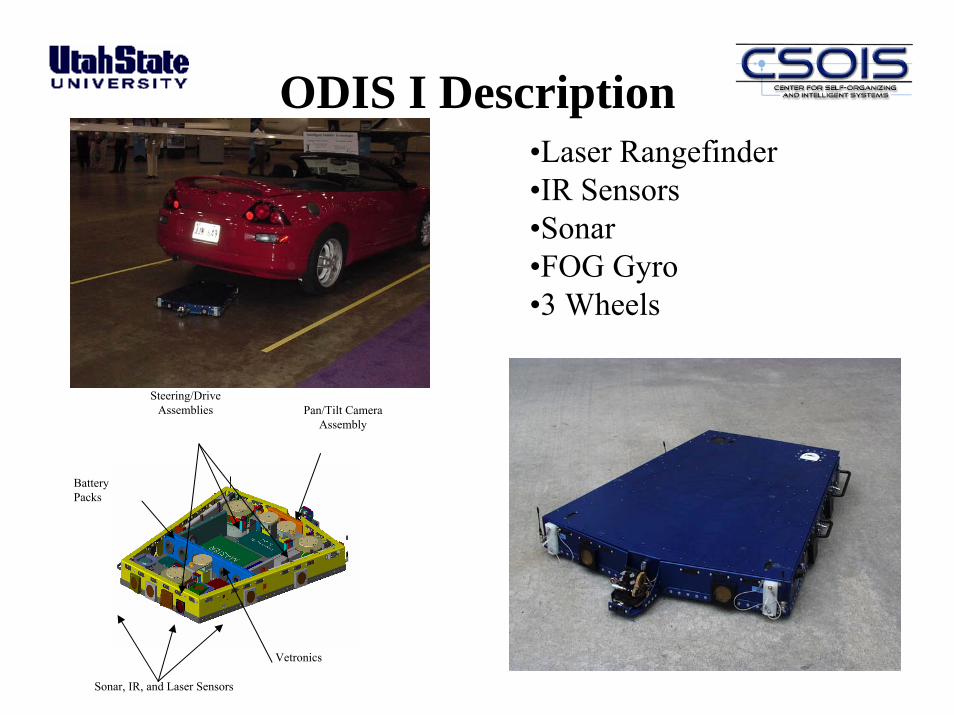
ODIS I Description
Steering/DriveAssemblies Pan/Tilt Camera
Assembly
Vetronics
Sonar, IR, and Laser Sensors
Battery Packs
•Laser Rangefinder•IR Sensors•Sonar•FOG Gyro•3 Wheels
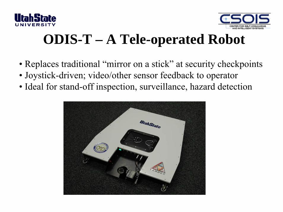
ODIS-T – A Tele-operated Robot• Replaces traditional “mirror on a stick” at security checkpoints• Joystick-driven; video/other sensor feedback to operator• Ideal for stand-off inspection, surveillance, hazard detection

ODIS Under Joystick Control(ODIS was designed and built in about four months)

“Mirror-on-a-Stick” vs. ODIS
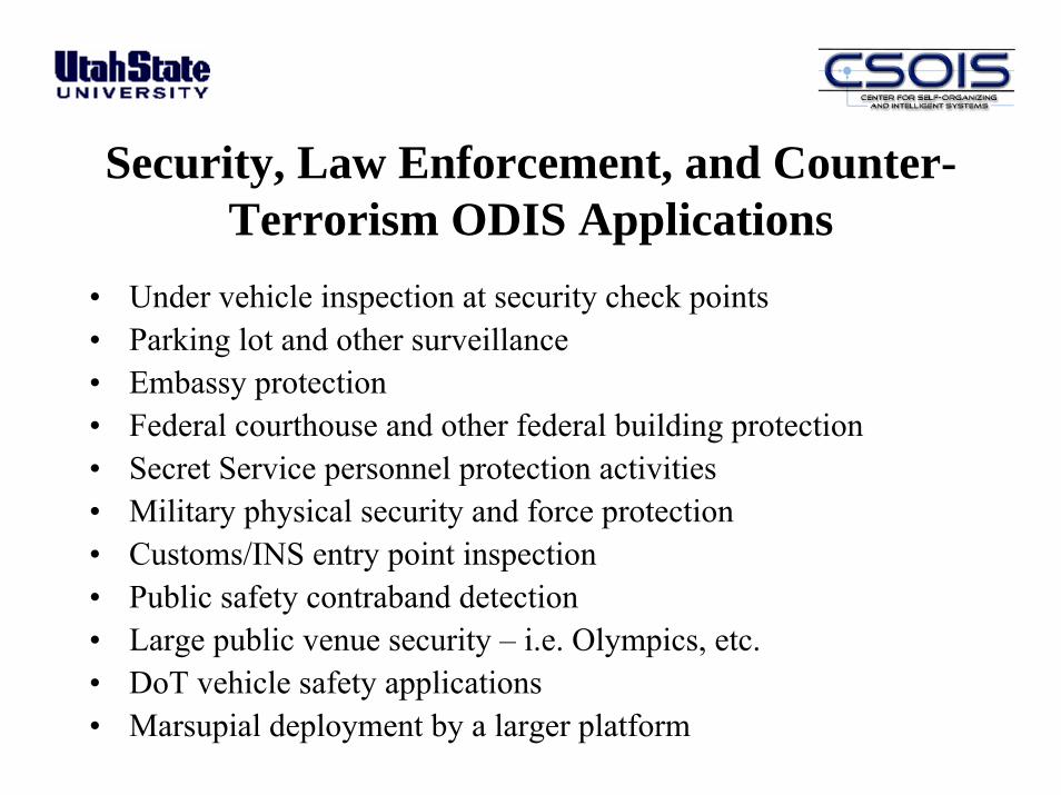
• Under vehicle inspection at security check points• Parking lot and other surveillance• Embassy protection• Federal courthouse and other federal building protection• Secret Service personnel protection activities• Military physical security and force protection • Customs/INS entry point inspection• Public safety contraband detection• Large public venue security – i.e. Olympics, etc.• DoT vehicle safety applications• Marsupial deployment by a larger platform
Security, Law Enforcement, and Counter-Terrorism ODIS Applications
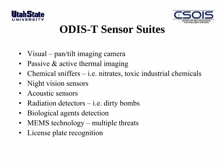
ODIS-T Sensor Suites
• Visual – pan/tilt imaging camera• Passive & active thermal imaging• Chemical sniffers – i.e. nitrates, toxic industrial chemicals• Night vision sensors• Acoustic sensors• Radiation detectors – i.e. dirty bombs• Biological agents detection• MEMS technology – multiple threats• License plate recognition
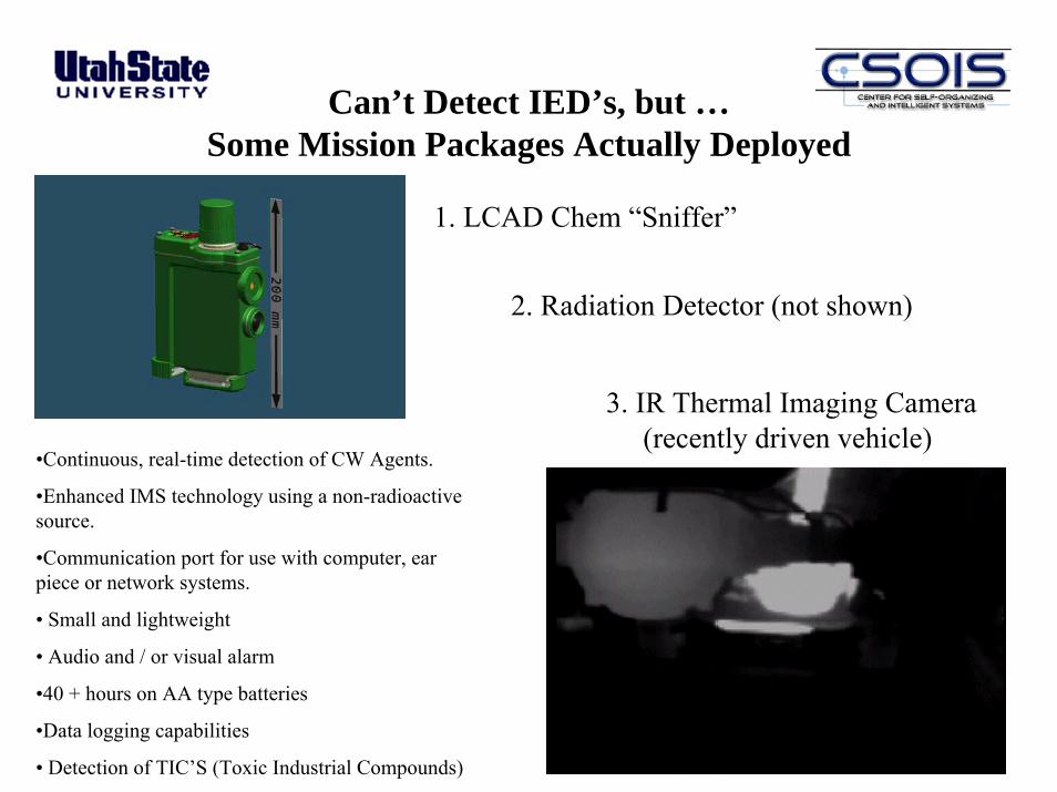
Can’t Detect IED’s, but …Some Mission Packages Actually Deployed
3. IR Thermal Imaging Camera (recently driven vehicle)
•Continuous, real-time detection of CW Agents.
•Enhanced IMS technology using a non-radioactive source.
•Communication port for use with computer, ear piece or network systems.
• Small and lightweight
• Audio and / or visual alarm
•40 + hours on AA type batteries
•Data logging capabilities
• Detection of TIC’S (Toxic Industrial Compounds)
2. Radiation Detector (not shown)
1. LCAD Chem “Sniffer”

Mission Packages - IR
IR Image – Warm Brake IR Image – Recently Driven Vehicle
ODIS Commercialization Status• Field tested the ODIS-T:
– in a Limited Objective Experiment (LOE) at the Ft. Leonard Wood (Mo.) Military Police School
– At the Los Angeles Port Authority, with CHP cooperation• Based on tests, have designed improved versions, the ODIS-S and the
ODIS-T2• A commercial license for ODIS-T2 has been negotiated between USU
and Kuchera• 20 ODIS-T2 robots have been built and will be deployed in
Afghanistan and Iraq in Feb, with additional acquisition expected• The ODIS-T2 technology can be considered COTS• USU and Kuchera are working to develop other types of robotic
mobility platforms for sensor payload delivery systems, both UGV and UAV
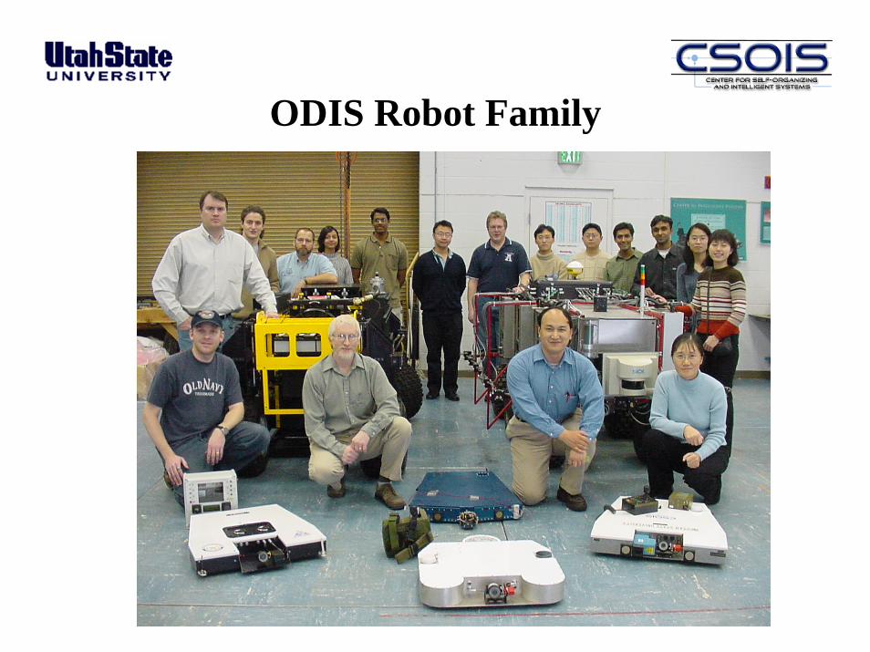
ODIS Robot Family
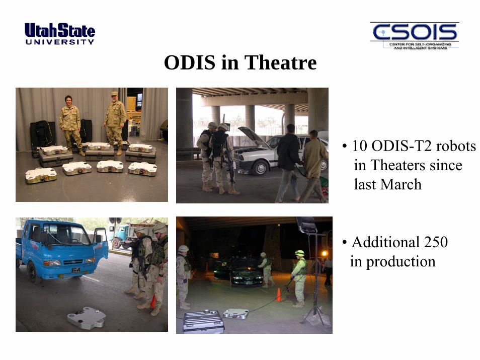
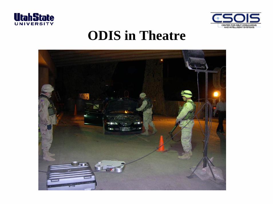
ODIS in Theatre
• 10 ODIS-T2 robotsin Theaters since last March
• Additional 250in production

ODIS in Theatre
• 10 ODIS-T2 robotsin Theaters since last March
• Additional 120in production
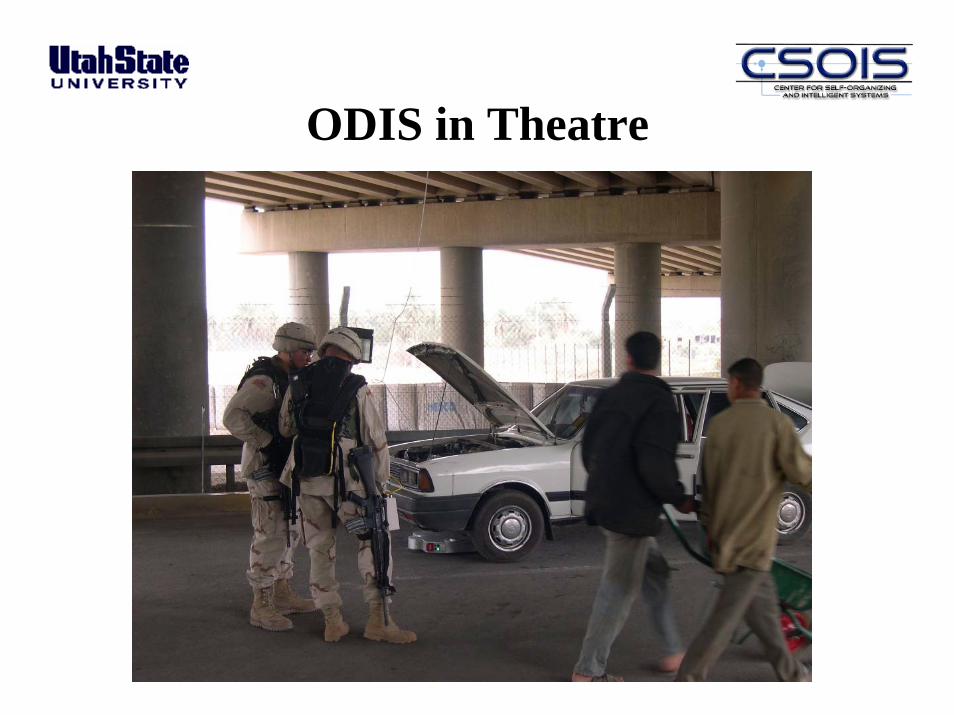
ODIS in Theatre

ODIS in Theatre
ODIS in Theatre
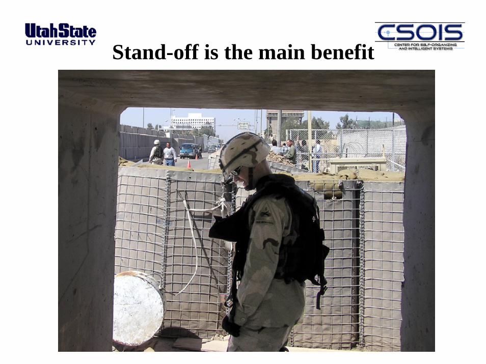
Stand-off is the main benefit
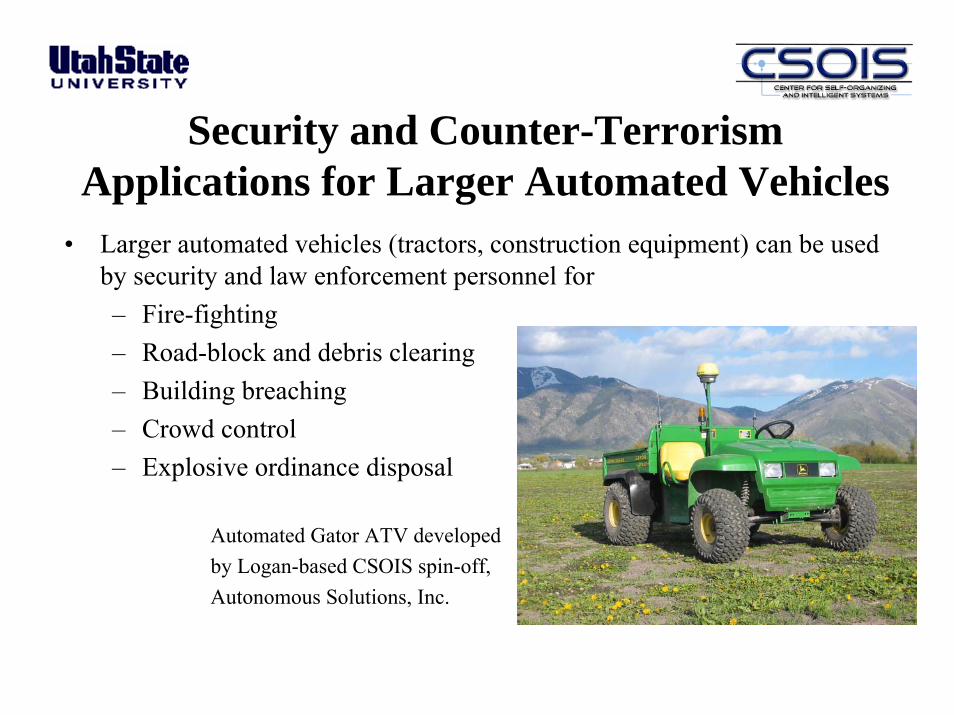
Security and Counter-Terrorism Applications for Larger Automated Vehicles
• Larger automated vehicles (tractors, construction equipment) can be used by security and law enforcement personnel for– Fire-fighting– Road-block and debris clearing– Building breaching– Crowd control– Explosive ordinance disposal
Automated Gator ATV developedby Logan-based CSOIS spin-off, Autonomous Solutions, Inc.
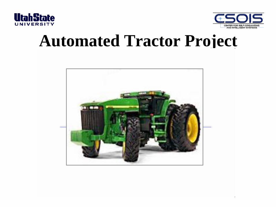
Automated Tractor Project
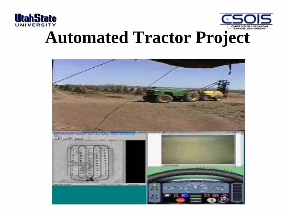
Automated Tractor Project
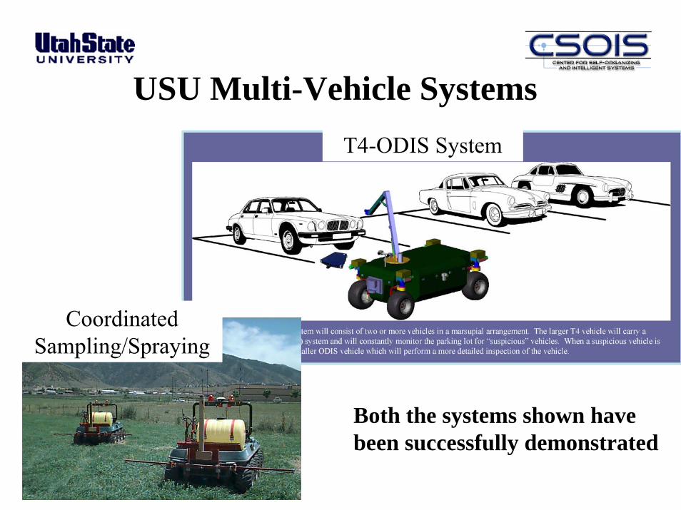
USU Multi-Vehicle SystemsT4-ODIS System
Coordinated Sampling/Spraying
Both the systems shown havebeen successfully demonstrated

T4 Parking Lot Surveillance Robot
• Omni-directional• Hydraulically driven• Gasoline Powered• Designed to work in
cooperation with ODIS
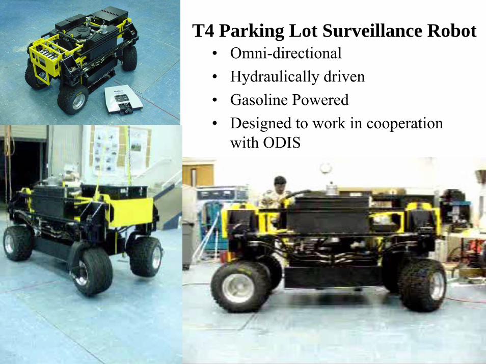
T4 Parking Lot Surveillance Robot• Omni-directional• Hydraulically driven• Gasoline Powered• Designed to work in cooperation
with ODIS
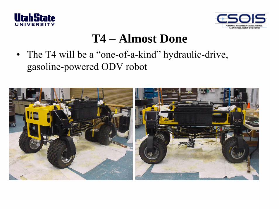
T4 – Almost Done• The T4 will be a “one-of-a-kind” hydraulic-drive,
gasoline-powered ODV robot
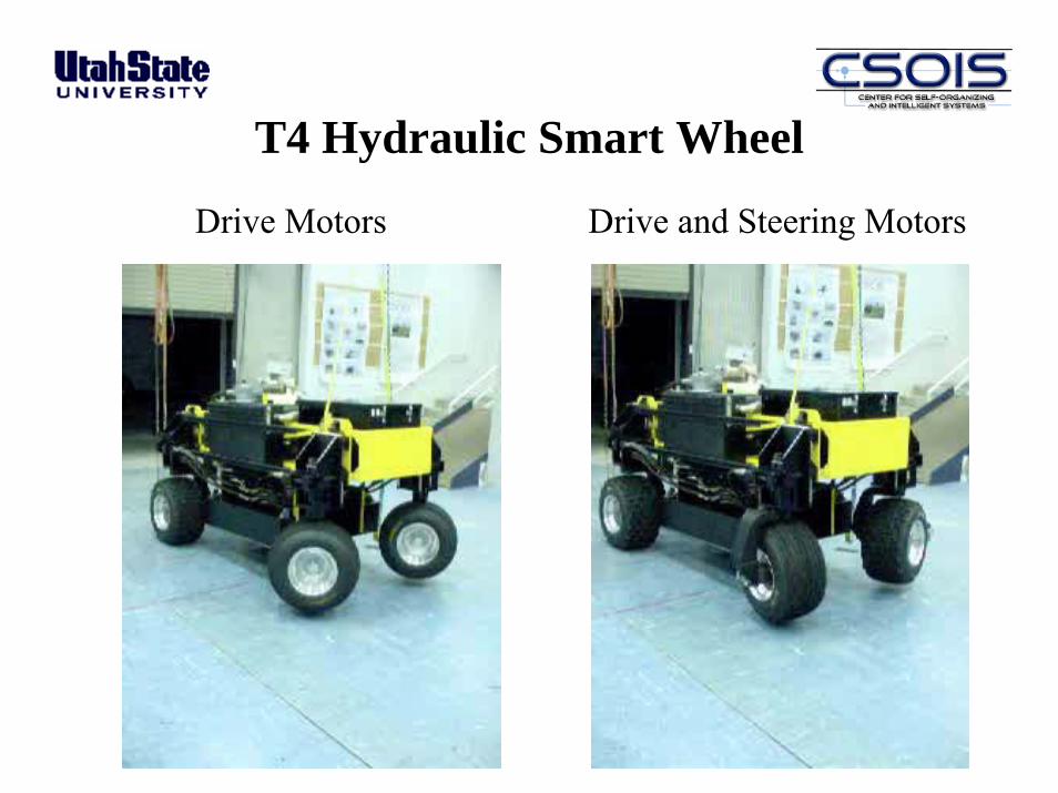
T4 Hydraulic Smart Wheel
Drive Motors Drive and Steering Motors
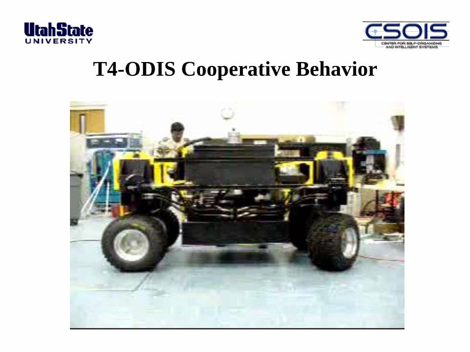
T4-ODIS Cooperative Behavior
Ve-Tronics
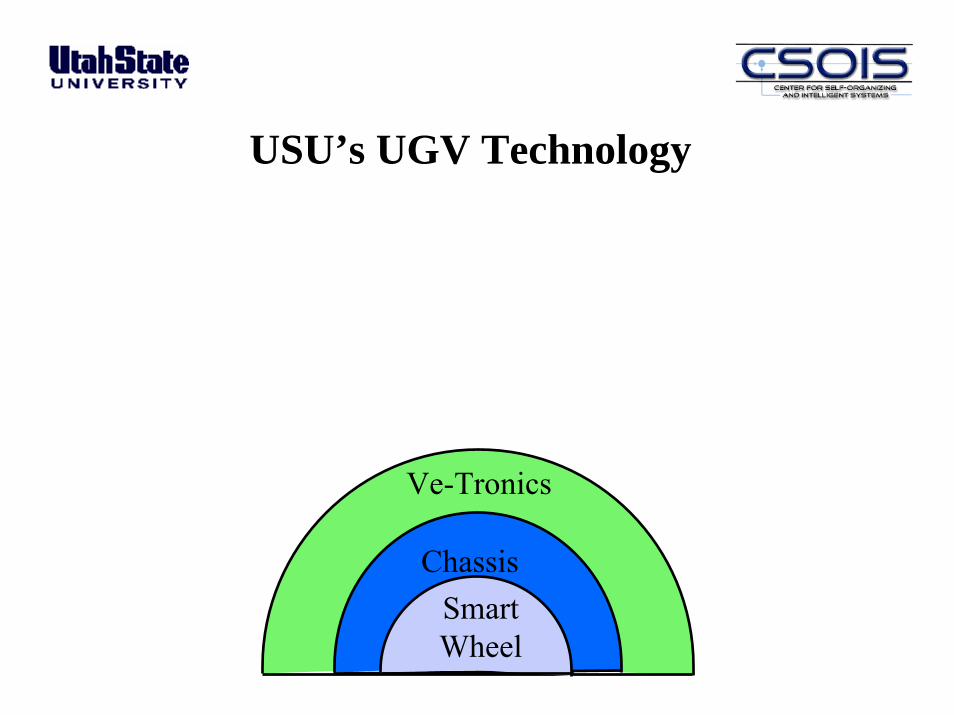
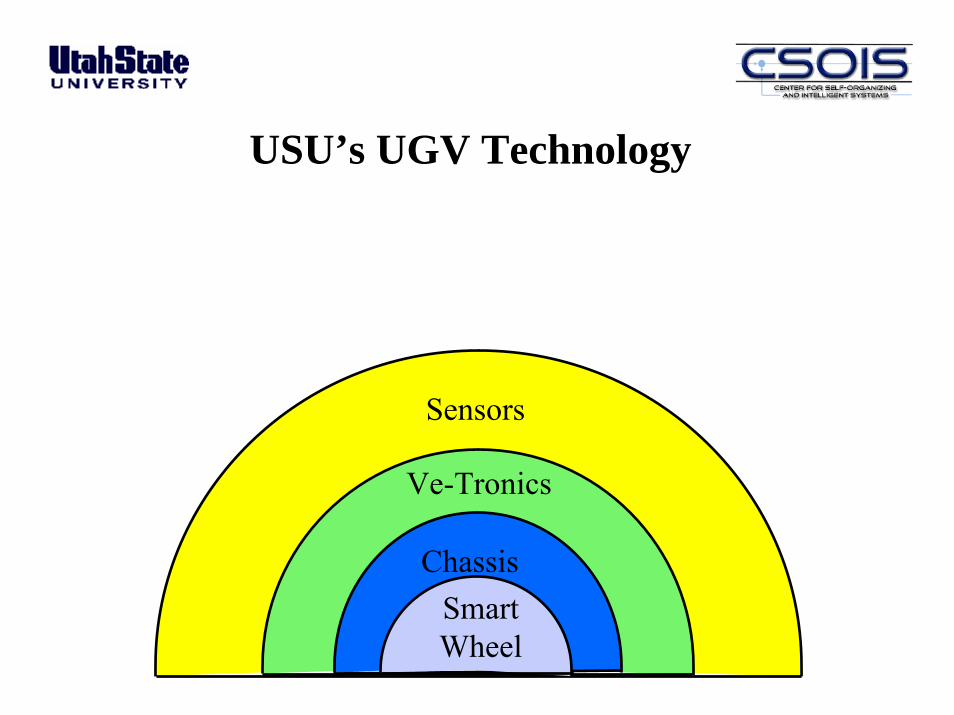
USU’s UGV Technology
ChassisSmartWheel

Master NodeSBC
Nav/SensorNodeSBC
MobilityPlanner Node
SBC
RS-232(PC104)
GPS, FOG,Compass
Other Sensors
Wheel NodeTT8 (x6)
RS-232(PCI)
CAN(PC104)
LAN
WirelessRS-232
WirelessTCP/IP
Joystick
RemoteOCU
Off-Vehicle On-Vehicle
T2 Vetronics Architecture
A/D IO(PC104)
System MonitorSensors

T2 Wheel Node(Hardware Diagram)
TT8Wheel NodeController
Master NodeSerial Interface
Failsafe BrakeWarnerERS57
Computer OpticalProducts
CP-560 (1024)
Quadrature Encoder
Absolute EncoderSequential Electronic
SystemsModel 40H
Drive Motor
Interface
Absolute EncoderInterface
Quadrature EncoderInterface
A/D SignalInterface
Current(2)
Power
Drive Motor Controller
Advanced Motion Controls50A8DD
Steering Motor
Interface
Steer Motor Controller
Advanced Motion Controls50A8D D
+12V12V ReturnChannel AChannel B
Direction
PWM FaultD-Current
DirectionPWM
FaultS-Current
+5V5V Return
Position10
Brake RelayBrake Power
Power Gnd
DPWMDDIRDfault
CHA
CHB
SPWM
SDIR
Sfault
ACLK
ADATAAENALBE
BRAKE OFF
Temp (2)Type K
Thermo-couple
Battery Voltage
Lambda PM30 SeriesDC-DC Converter
+12V-12V+5V
48V Bus and Motor ConnectionsNot shown
Sensors
Ve-Tronics
USU’s UGV Technology
ChassisSmartWheel
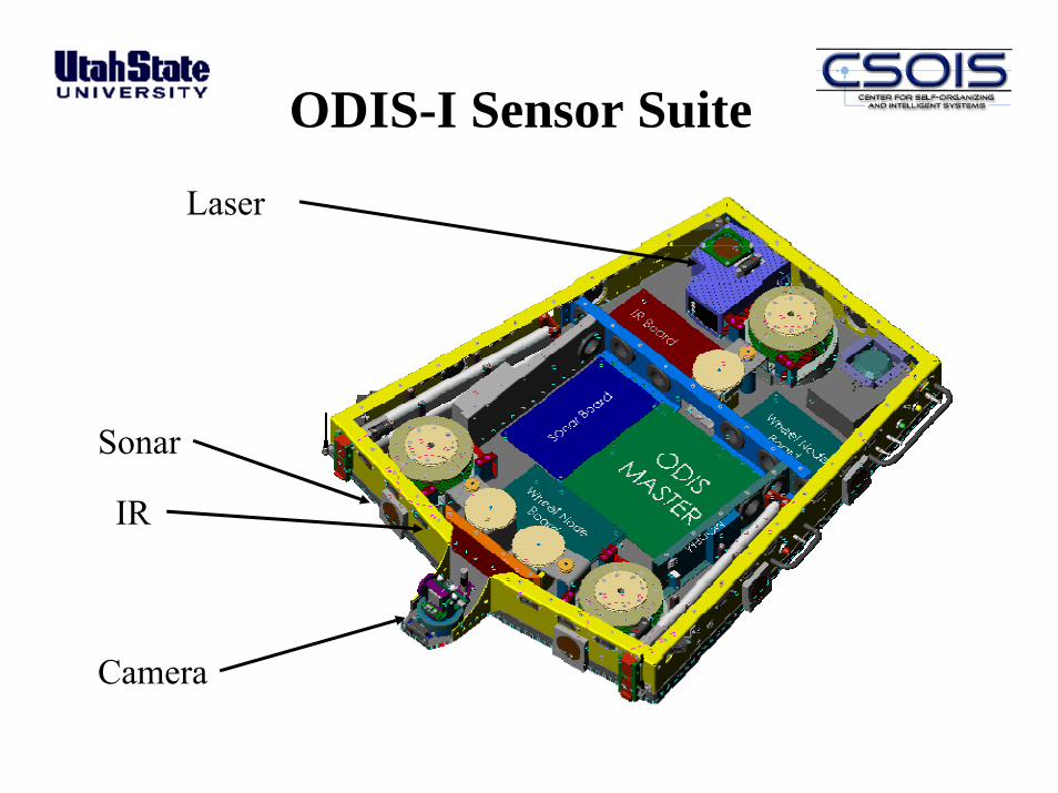
ODIS-I Sensor Suite
Laser
Sonar
IR
Camera
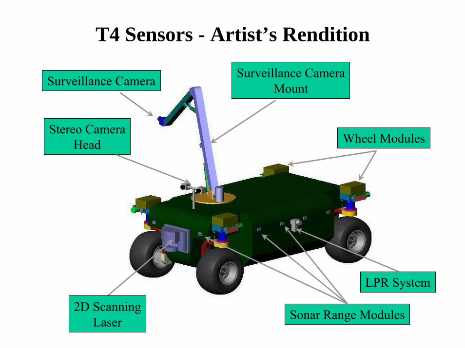
T4 Sensors - Artist’s Rendition
Surveillance CameraMountSurveillance Camera
Wheel Modules
LPR System
Sonar Range Modules2D ScanningLaser
Stereo CameraHead

T2e – A Testbed for T4 Behaviors• The T2 was equipped with the sensors and vetronics
that will be found on T4, to enable testing of intelligent behavior generation strategies; call it the T2e
Autonomous Vehicle Technology
• Autonomous vehicles are enabled by advances in:– Vehicle concept and mechanical design– Vehicle electronics (vetronics)– Sensors (e.g., GPS) and perception algorithms– Control– Planning
• We consider two key aspects of autonomy:– Inherent mobility capability built into the vehicle– Mobility control to exploit these capabilities
Just for Fun
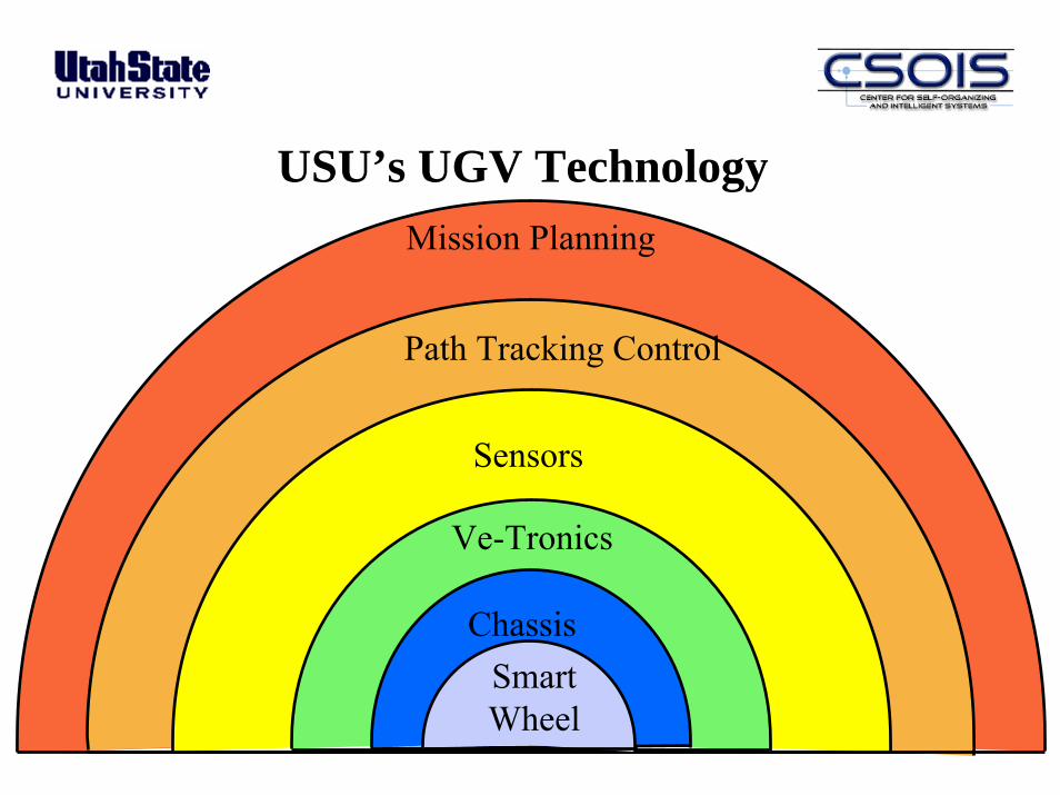
Mission Planning
Path Tracking Control
Sensors
Ve-Tronics
USU’s UGV Technology
ChassisSmartWheel
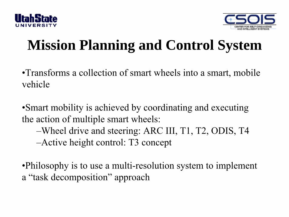
Mission Planning and Control System
•Transforms a collection of smart wheels into a smart, mobile vehicle
•Smart mobility is achieved by coordinating and executing the action of multiple smart wheels:
–Wheel drive and steering: ARC III, T1, T2, ODIS, T4–Active height control: T3 concept
•Philosophy is to use a multi-resolution system to implement a “task decomposition” approach
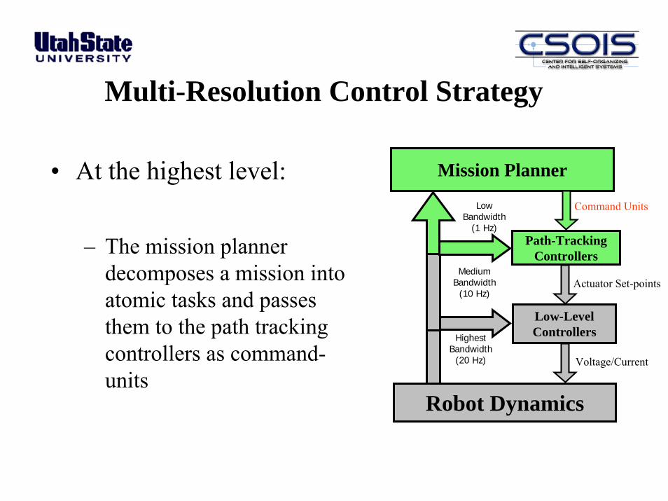
Multi-Resolution Control Strategy
Mission Planner
Robot Dynamics
Path-TrackingControllers
Low-LevelControllersHighest
Bandwidth(20 Hz)
Command Units
• At the highest level:
– The mission planner decomposes a mission into atomic tasks and passes them to the path tracking controllers as command-units
Low Bandwidth
(1 Hz)
Actuator Set-pointsMedium
Bandwidth(10 Hz)
Voltage/Current
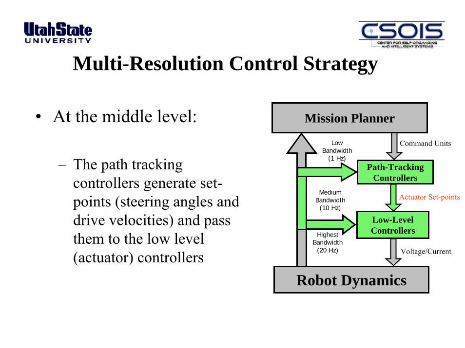
Multi-Resolution Control Strategy
• At the middle level:
– The path tracking controllers generate set-points (steering angles and drive velocities) and pass them to the low level (actuator) controllers
Mission Planner
Robot Dynamics
Path-TrackingControllers
Low-LevelControllersHighest
Bandwidth(20 Hz)
Command UnitsLowBandwidth
(1 Hz)
Actuator Set-pointsMediumBandwidth
(10 Hz)
Voltage/Current

Multi-Resolution Control Strategy
• At the lowest level:
– Actuators run the robot
Mission Planner
Robot Dynamics
Path-TrackingControllers
Low-LevelControllersHighest
Bandwidth(20 Hz)
Command UnitsLowBandwidth
(1 Hz)
Actuator Set-pointsMedium
Bandwidth(10 Hz)
Voltage/Current
Path Tracking Strategies
• Fundamental for behavior generation• Can be broadly classified into two groups
1. Time trajectory based (temporal)─Desired path is parameterized into time-varying set-
points─Locus of these set-points follow (in time) the desired
trajectory (in space)2. Spatial
• We have implemented a variety of each type of controller on our robots

• Indirect path tracking approach• Can generate unexpected results,
especially in presence of external disturbances and actuator saturation
• Positional errors due to this approach may cause the robot to “cut corners”
• Not suited for real time changes in desired speed along the path
Disadvantages of Time Trajectory Path Tracking
Desired trajectory parameterizedinto time varying set-points
Actual position ofthe WMR
Desired position ofthe WMR
Positionalerror

Spatial Path TrackingControl Law: The ε-Controller (Cε)
• Based completely on static inputs – the geometry of the desired path
• All desired paths are composed of either arc or line segments• Real time variations of the desired speed (Vd) along the paths
are allowed• Uses only the current position (χ) of the robot as the feedback
variable• References to time are avoided in the controller development
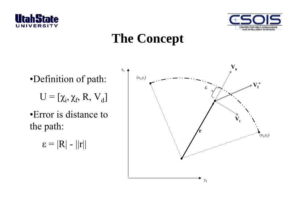
The Concept
yI
xI
r
(xi,yi)
(xf,yf)
ε
Vn
Vt
VI*
•Definition of path:
U = [χi, χf, R, Vd]
•Error is distance to the path:
ε = |R| - ||r||
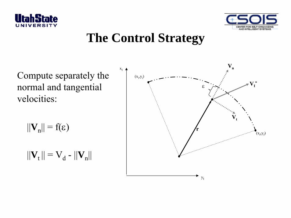
The Control Strategy
yI
xI
r
(xi,yi)
(xf,yf)
ε
Vn
Vt
VI*
Compute separately the normal and tangential velocities:
||Vn|| = f(ε)
||Vt || = Vd - ||Vn||

Cε Control Laws
• Proportional control was the baseline regulator for Cε :
Ur = Kp ε
• Another interesting concept we have introduced is the idea of a spatial Proportional-Integral controller:
Ur = Kp ε +
Actual Path
JArea
Desired Path
∫ dssKI )(ε
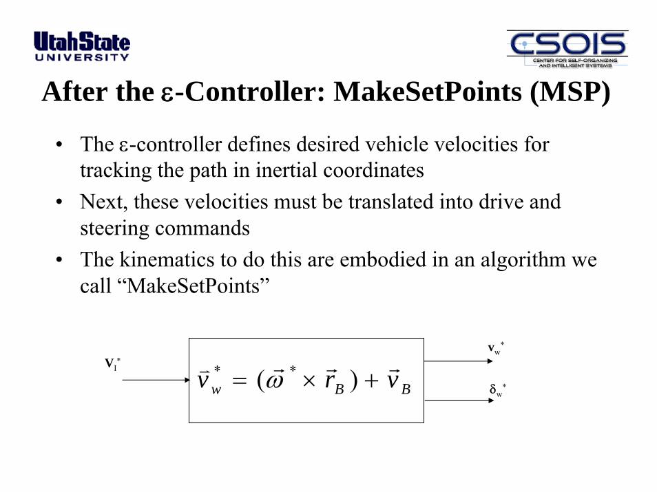
After the ε-Controller: MakeSetPoints (MSP)
VI*
δw*
vw*
BBw vrv rrrv +×= )( ** ω
• The ε-controller defines desired vehicle velocities for tracking the path in inertial coordinates
• Next, these velocities must be translated into drive and steering commands
• The kinematics to do this are embodied in an algorithm we call “MakeSetPoints”
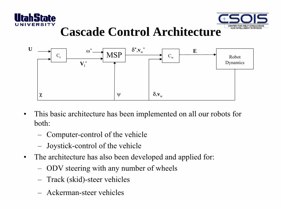
Cascade Control Architecture
Cε Cw RobotDynamics
MSP
δ,vwψχ
U
VI*
Eδ*,vw*ω*
• This basic architecture has been implemented on all our robots for both:– Computer-control of the vehicle– Joystick-control of the vehicle
• The architecture has also been developed and applied for:– ODV steering with any number of wheels– Track (skid)-steer vehicles
– Ackerman-steer vehicles

Modeling and Control (Epsilon Controller – on T1)
Experimental Results Dynamic Model Validation
0 2 4 6 8 10 120
2
4
6
8
X(m)
0 20 40 60 80 100 120 140 1600
20
40
60
80
Orientation of Vehicle
Ti ( )
0.58 m/sec
0.205 m/sec
0.82 m/sec
0.41 m/sec
0 2 4 6 8 10 120
2
4
6
8
X(m)
Y(m
)
0 20 40 60 80 100 120 140 1600
20
40
60
80
Orientation of Vehicle
Ti ( )

T2 Path-Tracking Control
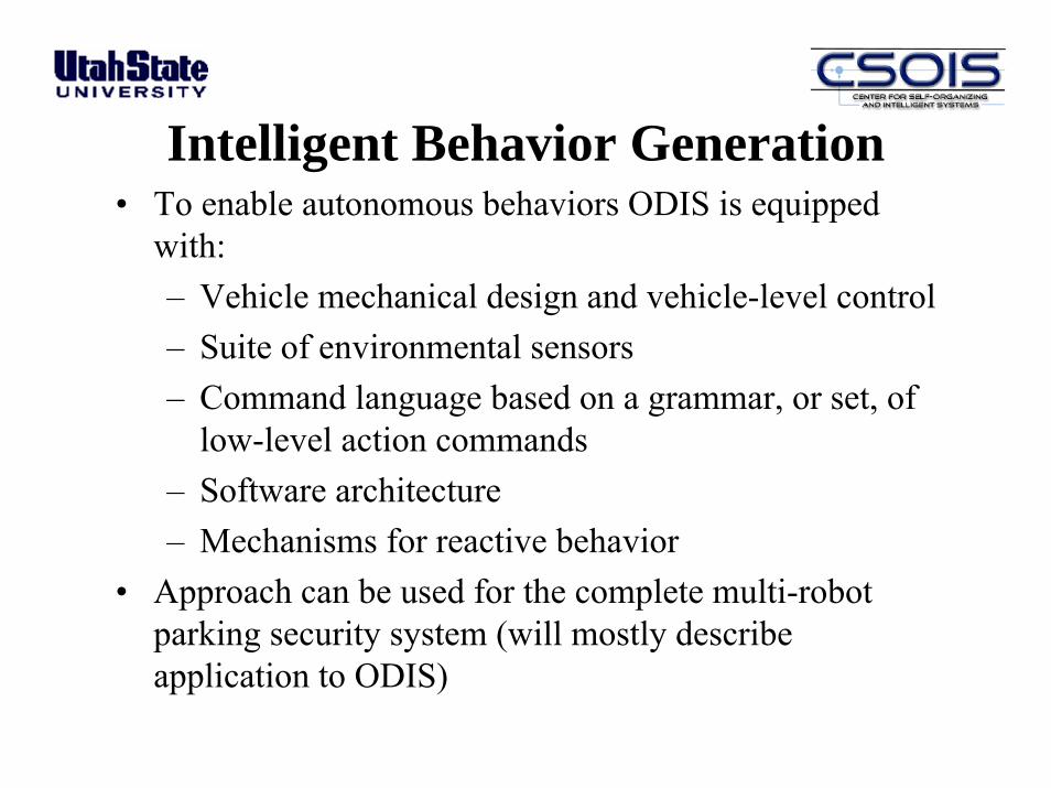
Intelligent Behavior Generation• To enable autonomous behaviors ODIS is equipped
with:– Vehicle mechanical design and vehicle-level control– Suite of environmental sensors– Command language based on a grammar, or set, of
low-level action commands– Software architecture– Mechanisms for reactive behavior
• Approach can be used for the complete multi-robot parking security system (will mostly describe application to ODIS)
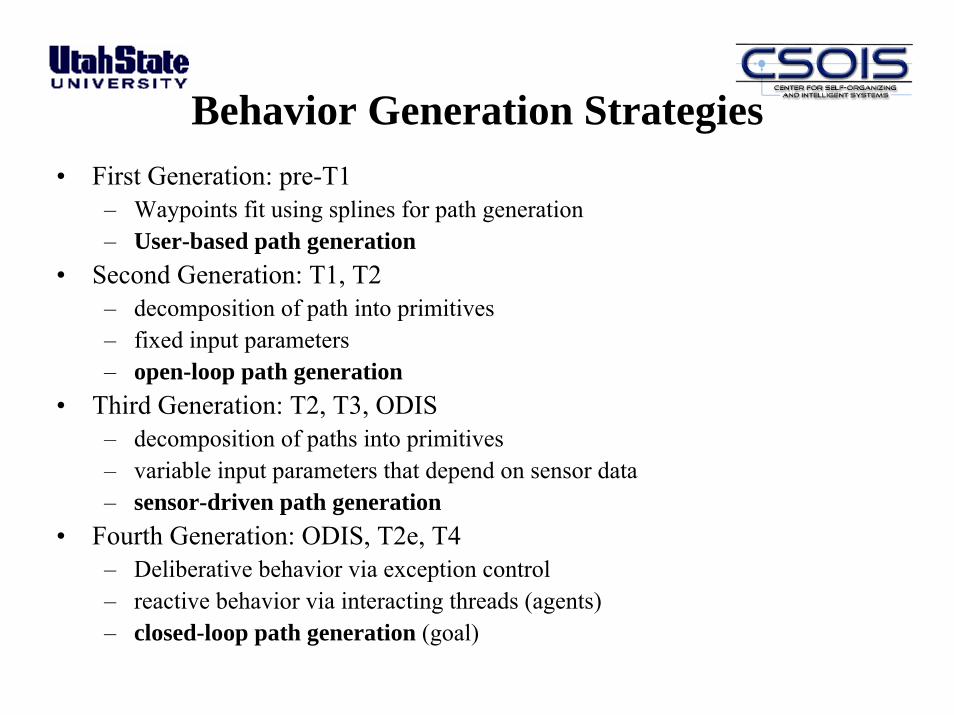
Behavior Generation Strategies• First Generation: pre-T1
– Waypoints fit using splines for path generation– User-based path generation
• Second Generation: T1, T2– decomposition of path into primitives– fixed input parameters– open-loop path generation
• Third Generation: T2, T3, ODIS– decomposition of paths into primitives– variable input parameters that depend on sensor data – sensor-driven path generation
• Fourth Generation: ODIS, T2e, T4– Deliberative behavior via exception control– reactive behavior via interacting threads (agents)– closed-loop path generation (goal)
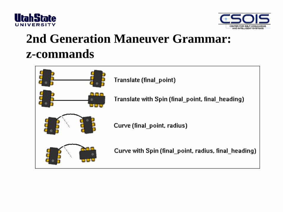
2nd Generation Maneuver Grammar:z-commands
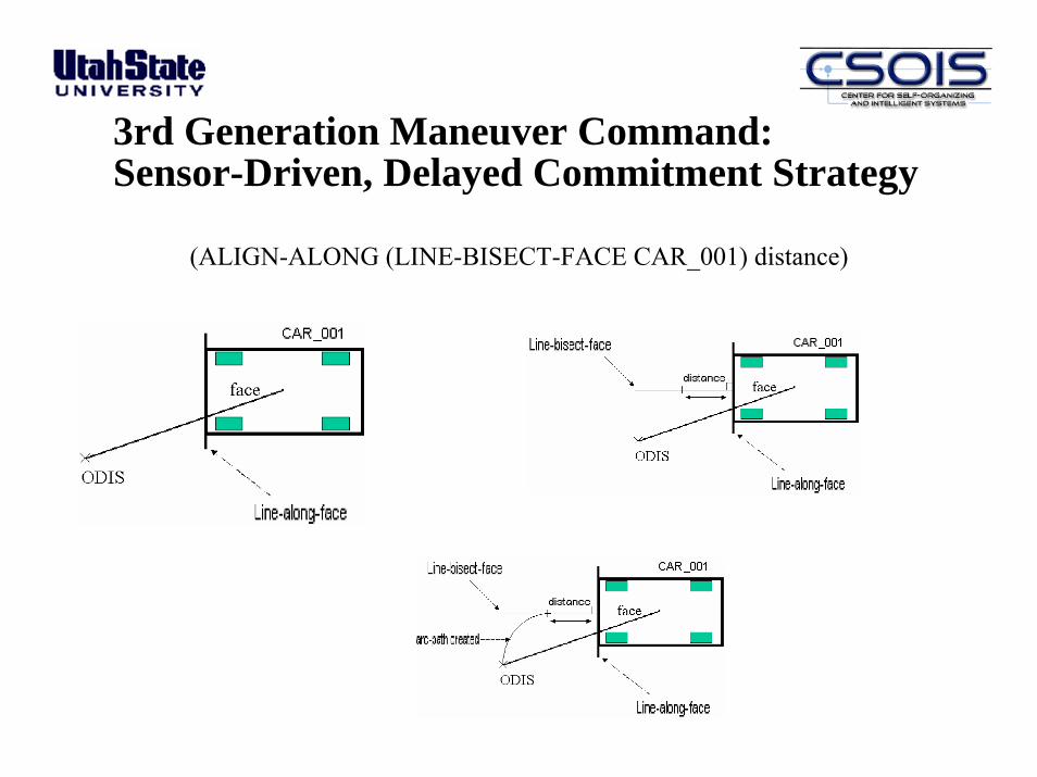
3rd Generation Maneuver Command:Sensor-Driven, Delayed Commitment Strategy
(ALIGN-ALONG (LINE-BISECT-FACE CAR_001) distance)

ODIS Command Environment - 1
• Developed to implement our delayed commitment approach• Called MoRSE (Mobile Robots in Structured Environments)• Has a high degree of orthogonality:
– a number of small orthogonal constructs– mixed and matched to provide almost any behavior– effectively spans the action space of the robot
• Initial implementation was an actual compiled language that we wrote to use a familiar imperative programming style, with looping constructs, conditional execution, and interpretive operation
• Later changed to a set of C libraries
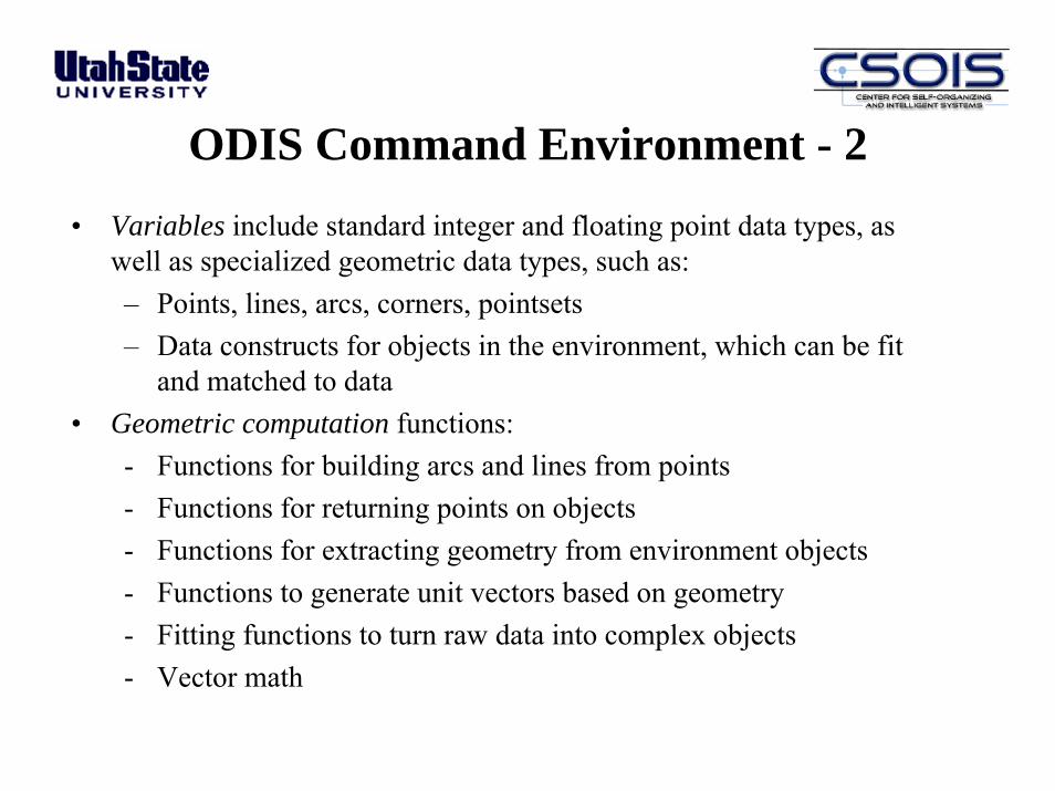
ODIS Command Environment - 2• Variables include standard integer and floating point data types, as
well as specialized geometric data types, such as: – Points, lines, arcs, corners, pointsets– Data constructs for objects in the environment, which can be fit
and matched to data• Geometric computation functions:
- Functions for building arcs and lines from points- Functions for returning points on objects- Functions for extracting geometry from environment objects- Functions to generate unit vectors based on geometry- Fitting functions to turn raw data into complex objects- Vector math
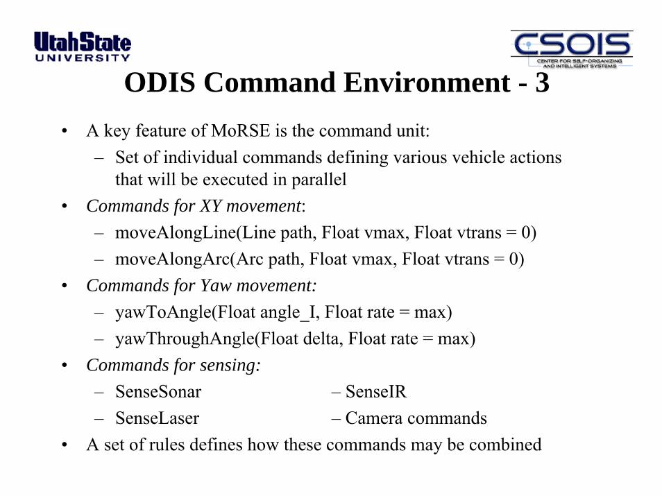
ODIS Command Environment - 3• A key feature of MoRSE is the command unit:
– Set of individual commands defining various vehicle actions that will be executed in parallel
• Commands for XY movement:– moveAlongLine(Line path, Float vmax, Float vtrans = 0)– moveAlongArc(Arc path, Float vmax, Float vtrans = 0)
• Commands for Yaw movement:– yawToAngle(Float angle_I, Float rate = max)– yawThroughAngle(Float delta, Float rate = max)
• Commands for sensing:– SenseSonar – SenseIR– SenseLaser – Camera commands
• A set of rules defines how these commands may be combined
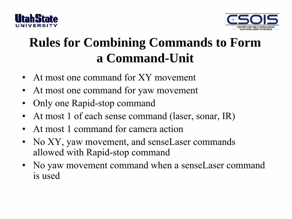
Rules for Combining Commands to Form a Command-Unit
• At most one command for XY movement• At most one command for yaw movement• Only one Rapid-stop command• At most 1 of each sense command (laser, sonar, IR)• At most 1 command for camera action• No XY, yaw movement, and senseLaser commands
allowed with Rapid-stop command• No yaw movement command when a senseLaser command
is used
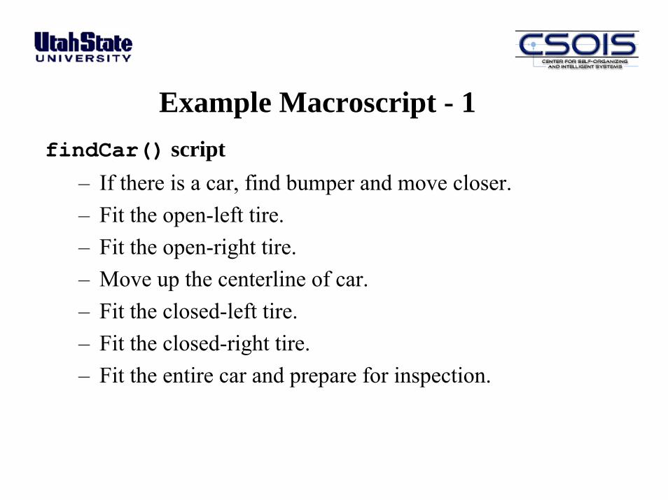
Example Macroscript - 1findCar() script
– If there is a car, find bumper and move closer.– Fit the open-left tire.– Fit the open-right tire.– Move up the centerline of car.– Fit the closed-left tire.– Fit the closed-right tire.– Fit the entire car and prepare for inspection.
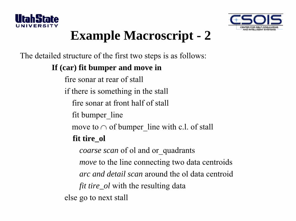
Example Macroscript - 2The detailed structure of the first two steps is as follows:
If (car) fit bumper and move infire sonar at rear of stallif there is something in the stall
fire sonar at front half of stallfit bumper_linemove to ∩ of bumper_line with c.l. of stallfit tire_ol
coarse scan of ol and or_quadrantsmove to the line connecting two data centroidsarc and detail scan around the ol data centroidfit tire_ol with the resulting data
else go to next stall
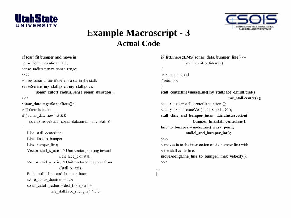
Example Macroscript - 3Actual Code
If (car) fit bumper and move insense_sonar_duration = 1.0;sense_radius = max_sonar_range;<<<// fires sonar to see if there is a car in the stall.senseSonar( my_stall.p_cl, my_stall.p_cr,
sonar_cutoff_radius, sense_sonar_duration );>>>sonar_data = getSonarData();// If there is a car.if ( sonar_data.size > 5 &&
pointIsInsideStall ( sonar_data.mean(),my_stall )){
Line stall_centerline;Line line_to_bumper;Line bumper_line;Vector stall_x_axis; // Unit vector pointing toward
//the face_c of stall.Vector stall_y_axis; // Unit vector 90 degrees from
//stall_x_axis.Point stall_cline_and_bumper_inter;sense_sonar_duration = 4.0;sonar_cutoff_radius = dist_from_stall +
my_stall.face_r.length() * 0.5;
if( fitLineSegLMS( sonar_data, bumper_line ) <=minimumConfidence )
{// Fit is not good.?return 0;}stall_centerline=makeLine(my_stall.face_o.midPoint()
,my_stall.center() );stall_x_axis = stall_centerline.unitvec();stall_y_axis = rotateVec( stall_x_axis, 90 );stall_cline_and_bumper_inter = LineIntersection(
bumper_line,stall_centerline );line_to_bumper = makeLine( entry_point,
stallcl_and_bumper_int );<<<// moves in to the intersection of the bumper line with// the stall centerline.moveAlongLine( line_to_bumper, max_velocity );>>>
…}

Example: ODIS FindCar() Script
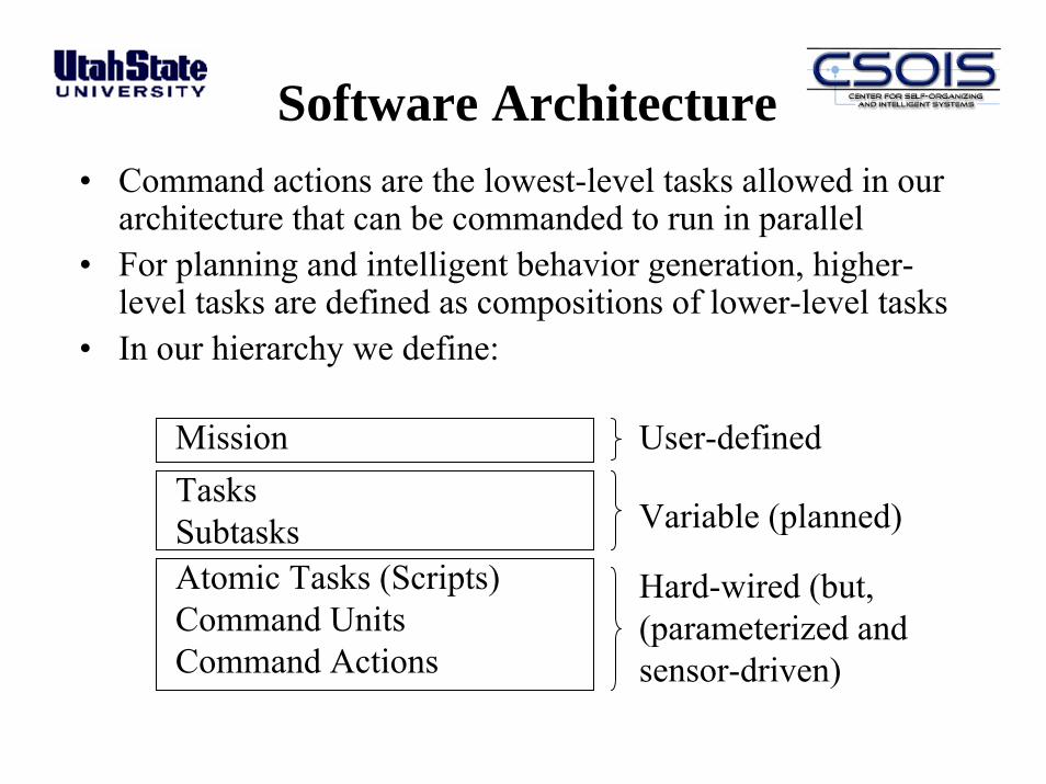
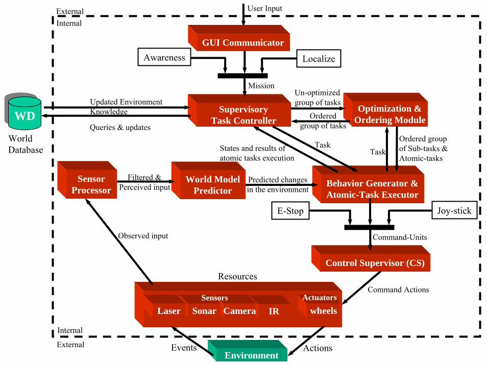
Software Architecture• Command actions are the lowest-level tasks allowed in our
architecture that can be commanded to run in parallel• For planning and intelligent behavior generation, higher-
level tasks are defined as compositions of lower-level tasks• In our hierarchy we define:
Variable (planned)
Hard-wired (but,(parameterized andsensor-driven)
User-definedMissionTasksSubtasksAtomic Tasks (Scripts)Command UnitsCommand Actions
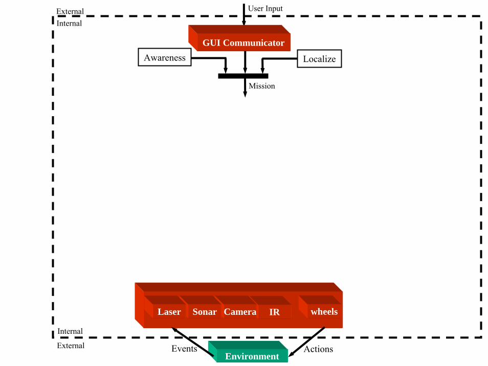
Environment
ExternalInternal
External
Internal
User Input
Mission
ActionsEvents
IRCamera wheels
GUI CommunicatorAwareness Localize
SonarLaser

Farming Automation Projects
• Optimal Intelligent and Co-operative path and mission planning
• Using an aircraft or satellite map of the region, user assigned tasks are optimized using the intelligent path and mission planner
• The system adapts to unexpected obstacles or terrain features by re-planning optimal mission and path assignments
• Technology developed for use on various autonomously controlled vehicles using dGPS navigation
• Prototypes equipped with soil sampling equipment, chemical applicators, radiation detectors, etc.
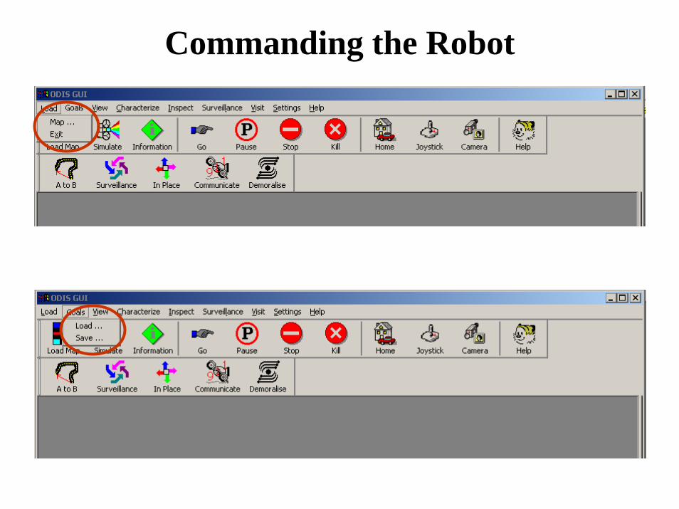
Commanding the Robot
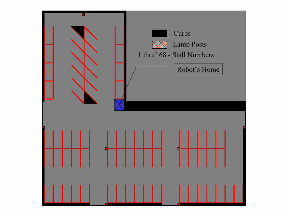
01 02 03 04 05 06 07 08 09 10 11
19 20 21 22 23 24 25 26 27 28 29 30 31 32 33 34
35 36 37 38 39 46 47 48 49 50
51
52
53
54
55
56
57
58
59 60
61
62
63
64 65
66
67
68
12 13 14 15 16 17 18
40 41 42 43 44 45
Robot’s Home
- Curbs- Lamp Posts
1 thru’ 68 - Stall Numbers
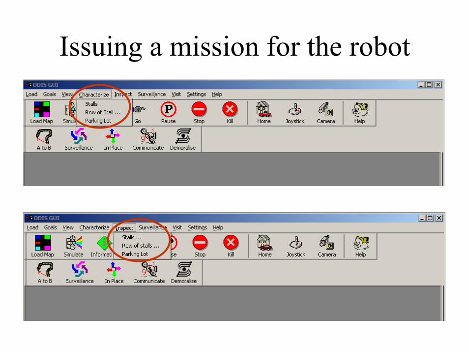
Issuing a mission for the robot
Row 1
Row 4
Row 7
Row 2
Row 5
Row 8
Row 3
Row 6
Row 9
Row
10
Row
11
Row
12
Row
13
- Row Definitions
Robot’s Home
1 thru’ 13 - Row Numbers

User-tasks in the environment
• {MoveTo Point}• {Characterize a stall}• {Inspect a stall}• {Characterize a row of stalls}• {Inspect a row of stalls}• {Localize}• {Find my Car}• {Sweep the parking lot}• {Sweep Specific area of the parking lot}

Environment
ExternalInternal
External
Internal
User Input
Mission
ActionsEvents
IRCamera wheels
GUI CommunicatorAwareness Localize
SonarLaser
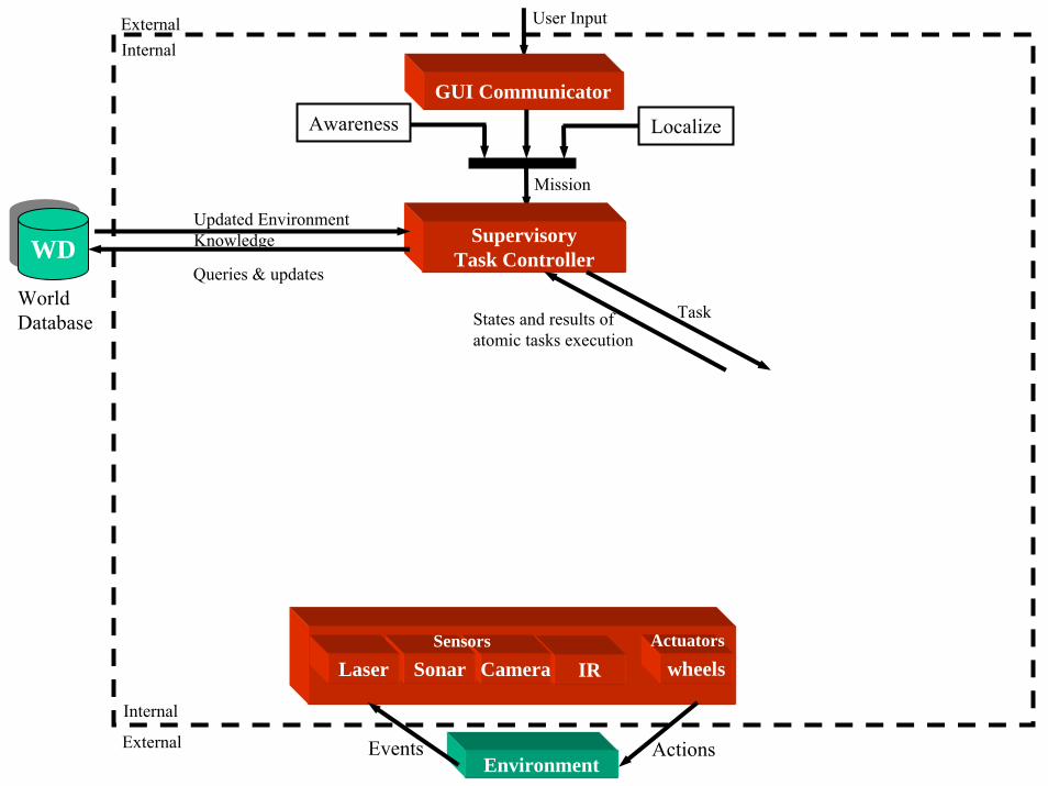
Environment
WorldDatabase
ExternalInternal
External
Internal
User Input
Mission
ActionsEvents
IRCamera wheelsActuators
GUI CommunicatorAwareness Localize
SonarLaserSensors
SupervisoryTask Controller
Queries & updates
Updated EnvironmentKnowledge
TaskStates and results ofatomic tasks execution
WDWD
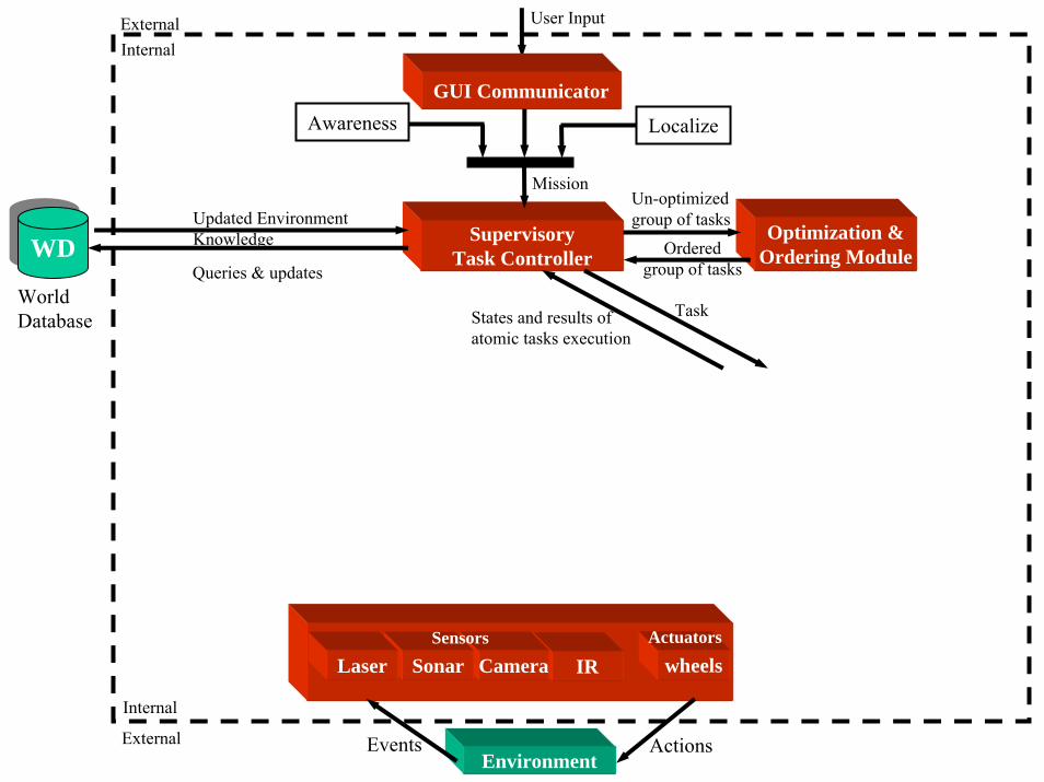
SupervisoryTask Controller
Environment
WorldDatabase
ExternalInternal
External
Internal
User Input
Mission
Queries & updates
Updated EnvironmentKnowledge
ActionsEvents
IRCamera wheelsActuators
Optimization &Ordering Module
Un-optimizedgroup of tasks
Orderedgroup of tasks
GUI CommunicatorAwareness Localize
WDWD
SonarLaserSensors
TaskStates and results ofatomic tasks execution
Behavior Generator &Atomic-Task Executor
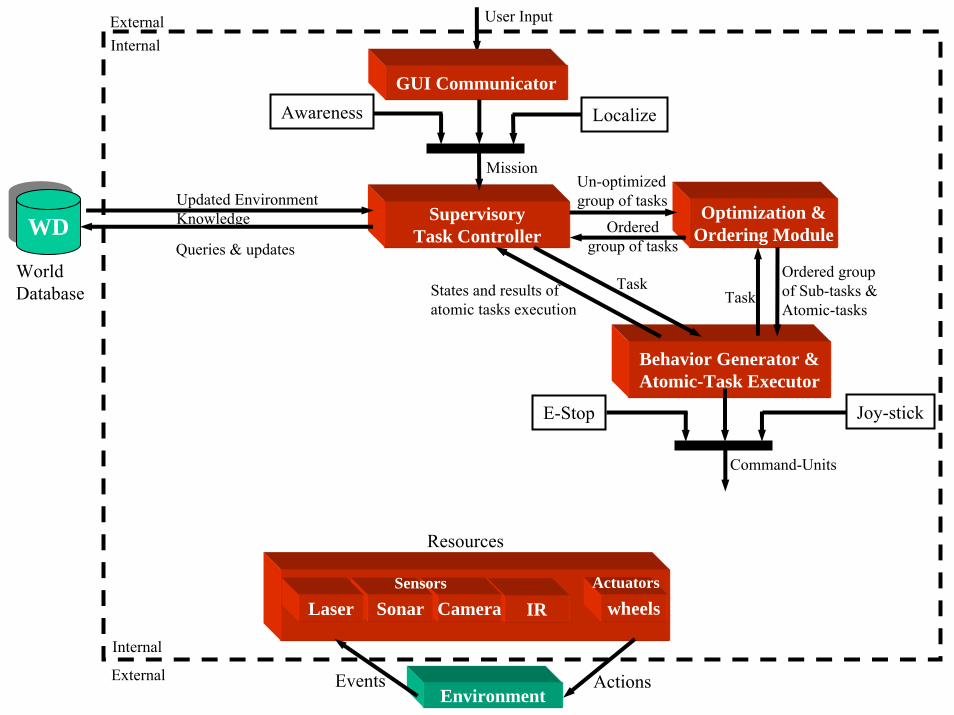
SupervisoryTask Controller
Optimization &Ordering Module
Environment
WorldDatabase
ExternalInternal
External
Internal
User Input
MissionUn-optimizedgroup of tasks
Orderedgroup of tasksQueries & updates
Updated EnvironmentKnowledge
ActionsEvents
IRCamera wheelsActuators
Resources
Ordered groupof Sub-tasks &Atomic-tasks
Task
GUI CommunicatorAwareness Localize
WDWD
SonarLaserSensors
TaskStates and results ofatomic tasks execution
Command-Units
Joy-stickE-Stop

Behavior Generator &Atomic-Task Executor
SupervisoryTask Controller
Optimization &Ordering Module
Environment
WorldDatabase
ExternalInternal
External
Internal
User Input
MissionUn-optimizedgroup of tasks
Orderedgroup of tasksQueries & updates
Updated EnvironmentKnowledge
ActionsEvents
IRCamera wheelsActuators
Resources
Ordered groupof Sub-tasks &Atomic-tasks
Task
GUI CommunicatorAwareness Localize
WDWD
SonarLaserSensors
SensorProcessor
TaskStates and results ofatomic tasks execution
Command-UnitsObserved input
Predicted changesin the environment
Filtered &Perceived input
Joy-stickE-Stop
World ModelPredictor
SupervisoryTask Controller
Behavior Generator &Atomic-Task Executor
Optimization &Ordering Module
Environment
SensorProcessor
WorldDatabase
ExternalInternal
External
Internal
User Input
MissionUn-optimizedgroup of tasks
Orderedgroup of tasksQueries & updates
Updated EnvironmentKnowledge
TaskStates and results ofatomic tasks execution
Actions
Command-Units
Events
Observed input
Predicted changesin the environment
Filtered &Perceived input
IRCamera wheelsActuators
Control Supervisor (CS)
Command ActionsResources
Ordered groupof Sub-tasks &Atomic-tasks
Task
Joy-stickE-Stop
GUI CommunicatorAwareness Localize
WDWD
SonarLaserSensors
World ModelPredictor
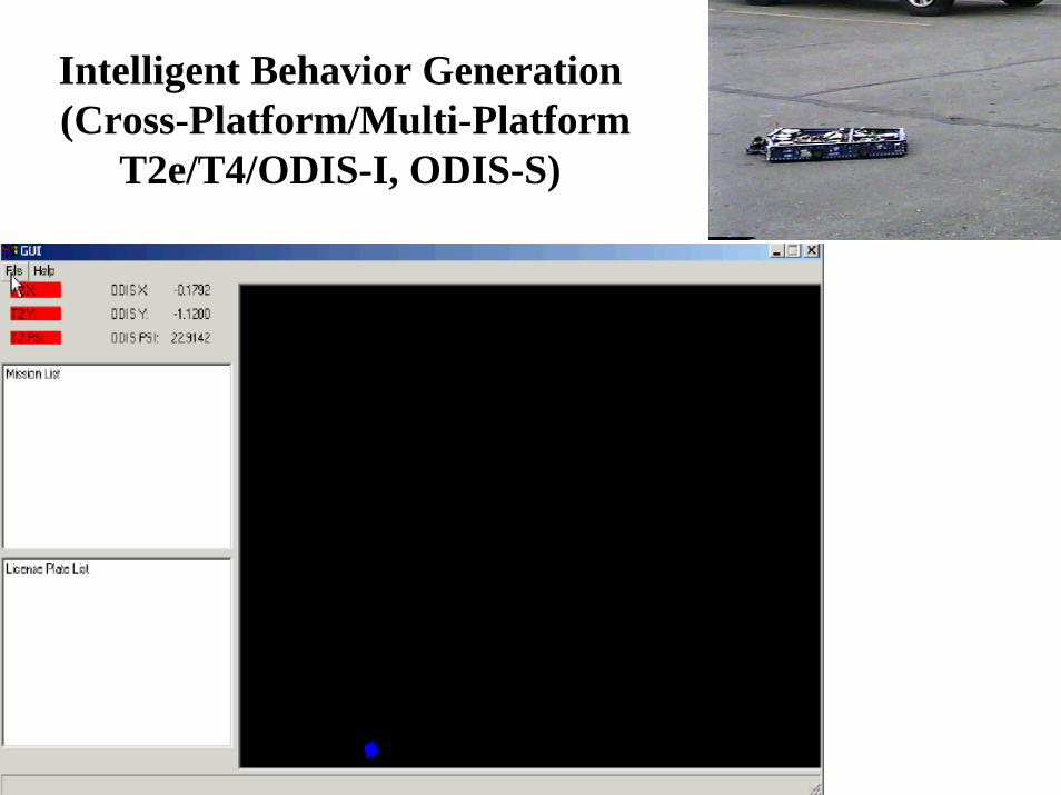
Intelligent Behavior Generation(Cross-Platform/Multi-Platform
T2e/T4/ODIS-I, ODIS-S)
Demonstration Example
Reactive BehaviorsReactive behaviors are induced via:1. Localization thread
– Compares expected positions to actual sensors’ data and makes correction to GPS and odometry as needed

Localization to Yellow Lines • Periodically the fiber-
optic gyro is reset:
- Yellow line is identified incamera image
- Vehicle is rotated to alignits body-centered axis withidentified line
- Process repeats iteratively
Reactive BehaviorsReactive behaviors are induced via:1. Localization thread
– Compares expected positions to actual sensors data and makes correction to GPS and odometry as needed
2. Awareness thread– Interacts with the execution thread based on safety
assessments of the environment

A taskA sub-taskAn atomic-taskA Command-unit
A task is decomposed intosub-tasks and the sub-tasksare ordered, if necessary by the O&O module
Sub-tasks may be furtherDecomposed into atomic-tasks,if they are not realizable in theircurrent form. Atomic-tasks may also be subjected to ordering.
Commandactions
A1 A2
Each Atomic-task getdirectly mapped to anatomic script, which canconsist of several command-units
Atomic-script
Plan path for the task based onthe partial environment knowledge
S1 S2 S3 S4 Sn-1 Sn
Environment
Localizing agent
Safety and obstacleavoiding agent
Localizemission
Modifications in the traveling velocities for slowing down
Re-plan
Plan aReactive path
Feedback loop for the“expected” situations
Reactive BehaviorsReactive behaviors are induced via:1. Localization thread
– Compares expected positions to actual sensors data and makes correction to GPS and odometry as needed
2. Awareness thread– Interacts with the execution thread based on safety
assessments of the environment3. Logic within the execution thread
– Exit conditions at each level of the hierarchy determine branching to pre-defined actions or to re-plan events
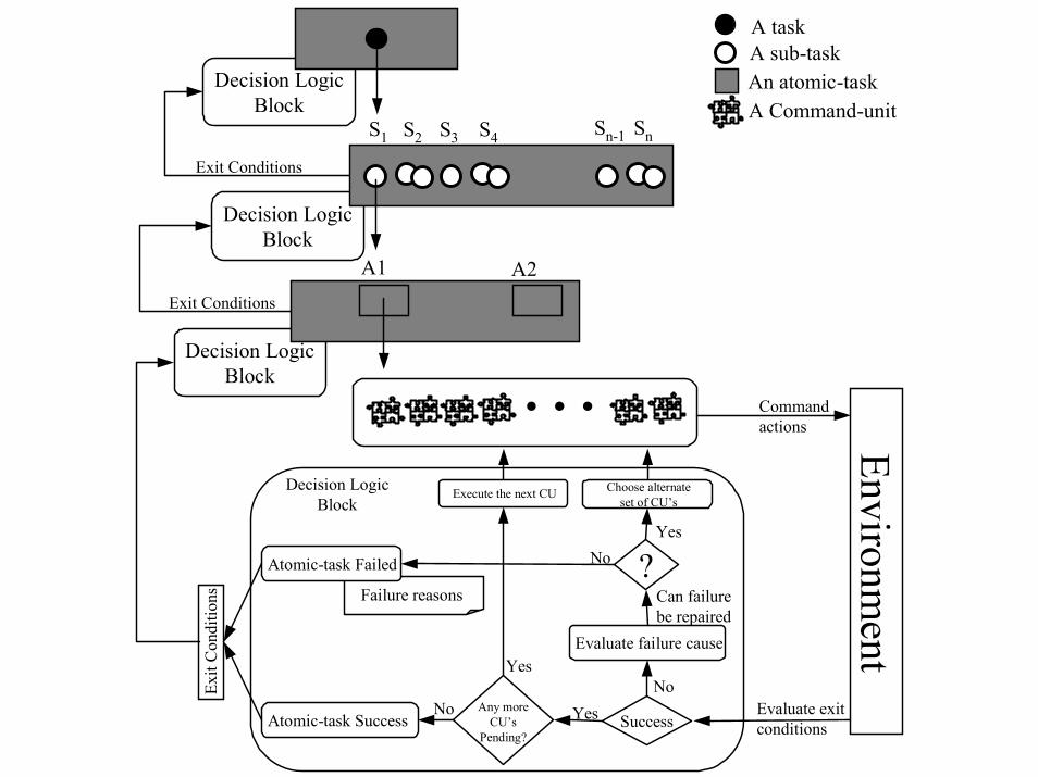
Decision LogicBlock
Decision LogicBlock
Decision LogicBlock
Failure reasons
A taskA sub-taskAn atomic-taskA Command-unit
Commandactions Environm
ent
…
Success
Evaluate failure cause
No
Evaluate exitconditions
?
Any moreCU’s
Pending?
Yes
Can failurebe repaired
Choose alternateset of CU’s
Yes
Execute the next CU
Yes
Atomic-task Success
Atomic-task Failed
NoNo
A1 A2
Exit
Con
ditio
ns
S1 S2 S3 S4 Sn-1 Sn
Decision LogicBlock
Exit Conditions
Exit Conditions
T2 Adaptive/Reactive Hill-Climbing
Conclusion• A variety of ODV robots have been presented• System architecture for enabling intelligent behaviors has been presented• The architecture is characterized by:
– A sensor-driven, parameterized low-level action command grammar– Multi-level planning and task decomposition– Multi-level feedback and decision-making
• Architecture enables adaptive, reactive behaviors• Longer-range goal is to incorporate automated script generation via discrete
event dynamic systems theory
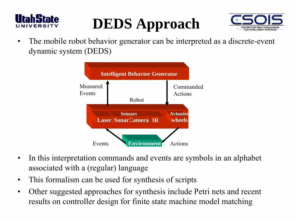
DEDS Approach• The mobile robot behavior generator can be interpreted as a discrete-event
dynamic system (DEDS)
• In this interpretation commands and events are symbols in an alphabet associated with a (regular) language
• This formalism can be used for synthesis of scripts• Other suggested approaches for synthesis include Petri nets and recent
results on controller design for finite state machine model matching
Sensors
Environment ActionsEvents
IRCamera wheelsActuators
Robot
SonarLaserSensors
Intelligent Behavior Generator
MeasuredEvents
CommandedActions
Conclusion• A variety of ODV robots have been presented• System architecture for enabling intelligent behaviors has been presented• The architecture is characterized by:
– A sensor-driven, parameterized low-level action command grammar– Multi-level planning and task decomposition– Multi-level feedback and decision-making
• Architecture enables adaptive, reactive behaviors• Longer-range goal is to incorporate automated script generation via discrete
event dynamic systems theory• Future applications are planned
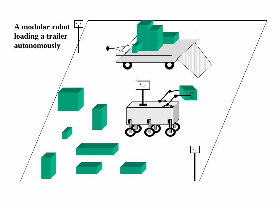
A modular robotloading a trailerautonomously

Mobile Flexible Manufacturing Cell(M-FMC)
- Two robots equipped with grasping endeffectors hold a pipe
- Third robot equipped with welding endeffector lays a bead
Three robots cooperatingon a welding task

Conclusion• A variety of ODV robots have been presented• System architecture for enabling intelligent behaviors has been presented• The architecture is characterized by:
– A sensor-driven, parameterized low-level action command grammar– Multi-level planning and task decomposition– Multi-level feedback and decision-making
• Architecture enables adaptive, reactive behaviors• Longer-range goal is to incorporate automated script generation via discrete
event dynamic systems theory• Future applications are planned• More details are available:
– Software architecture– Control systems– Visual servoing work
Robotics Research in General• Technical aspects (non-arm-based):
– Wheels– Legs– Wings– Fins– Scales
• Applications– Military– Homeland security– Industrial/Commercial/Agriculture– Consumer– Medical
• Groups/People– Academics (MIT/CMU Robotics Institute)– Companies (I-Robotics, Remotech)– Government Labs (Sandia, DoD)– Countries (Europe, Japan/Asia)

Some Links
Misc. Resource• http://www.geocities.com/roboticsresources/index.htmlMilitary/Government• DoD OSD Joint Program Office http://www.redstone.army.mil/ugvsjpo/• DARPA Grand Challenge http://www.darpa.mil/grandchallenge/index.htm• SPAWAR http://www.spawar.navy.mil/robots/• AFRL http://www.ml.afrl.af.mil/mlq/g-robotics.html• UAVs http://www.va.afrl.af.mil/CMU• http://www.ri.cmu.edu/Companies• http://www.remotec-andros.com/• http://www.irobot.com/home/default.aspOther Cool Stuff• Assistive technologies http://www.independencenow.com/ibot/index.html• Humanoid robots http://world.honda.com/ASIMO/• Lego Mindstorms http://www.lmsm.info/• Bartender http://www.roboyhd.fi/english/drinkkirobotti.html• WorkPartner http://www.automation.hut.fi/IMSRI/workpartner/index.html