intel server boards s3000ahlx, s3000ah, and s3000ahv · intel® server boards s3000ahlx, s3000ah,...
TRANSCRIPT
Intel® Server Boards S3000AHLX, S3000AH, and S3000AHV
Technical Product Specification
Intel Order Number: D72579-003
Revision 1.4
November 2008
Enterprise Platforms and Services Division
Revision History Intel® Server Boards S3000AHLX, S3000AH, and S3000AHV TPS
Revision 1.2
ii
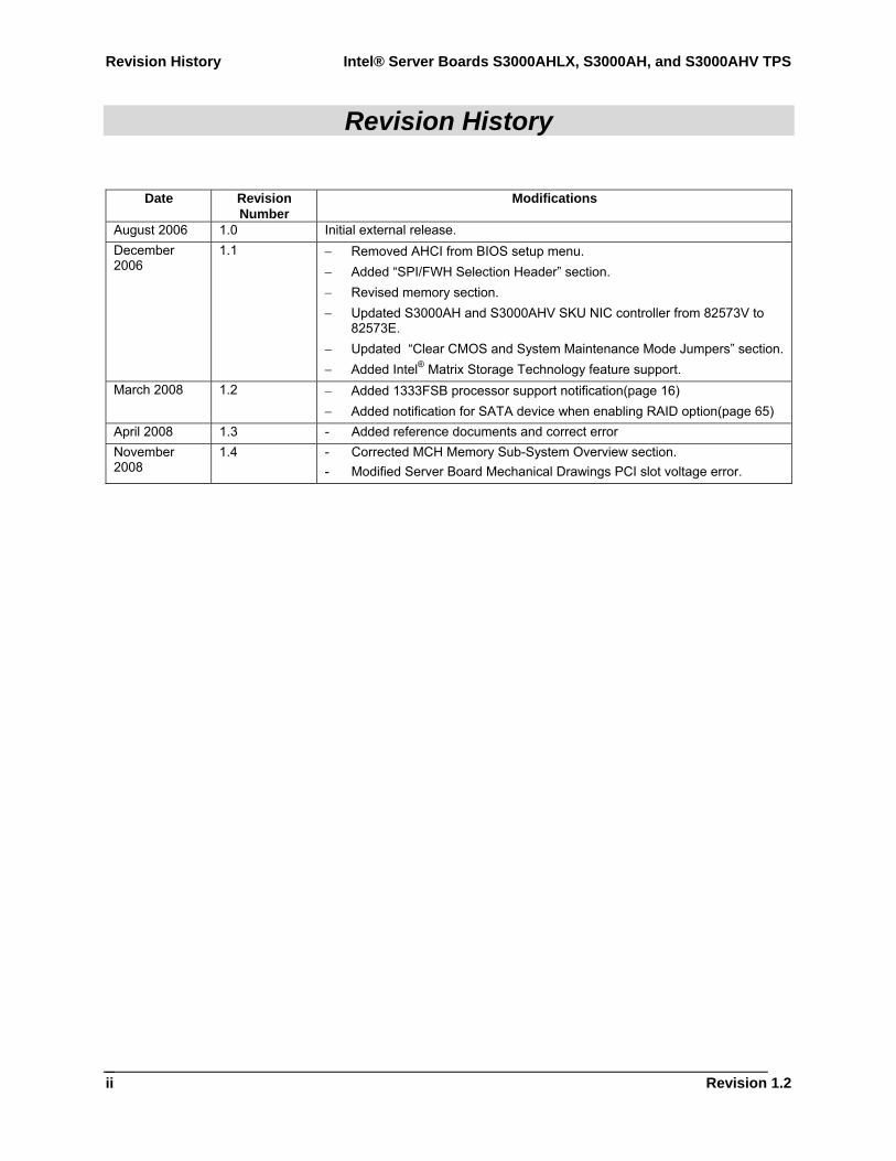
Revision History
Date Revision Number
Modifications
August 2006 1.0 Initial external release. December 2006
1.1 − Removed AHCI from BIOS setup menu. − Added “SPI/FWH Selection Header” section. − Revised memory section. − Updated S3000AH and S3000AHV SKU NIC controller from 82573V to
82573E. − Updated “Clear CMOS and System Maintenance Mode Jumpers” section. − Added Intel® Matrix Storage Technology feature support.
March 2008 1.2 − Added 1333FSB processor support notification(page 16) − Added notification for SATA device when enabling RAID option(page 65)
April 2008 1.3 - Added reference documents and correct error November 2008
1.4 - Corrected MCH Memory Sub-System Overview section. - Modified Server Board Mechanical Drawings PCI slot voltage error.

Intel® Server Boards S3000AHLX, S3000AH, and S3000AHV TPS Disclaimers
Revision 1.4
iii
Disclaimers Information in this document is provided in connection with Intel® products. No license, express or implied, by estoppel or otherwise, to any intellectual property rights is granted by this document. Except as provided in Intel's Terms and Conditions of Sale for such products, Intel assumes no liability whatsoever, and Intel disclaims any express or implied warranty, relating to sale and/or use of Intel products including liability or warranties relating to fitness for a particular purpose, merchantability, or infringement of any patent, copyright or other intellectual property right. Intel products are not intended for use in medical, life saving, or life sustaining applications. Intel may make changes to specifications and product descriptions at any time, without notice.
Designers must not rely on the absence or characteristics of any features or instructions marked "reserved" or "undefined." Intel reserves these for future definition and shall have no responsibility whatsoever for conflicts or incompatibilities arising from future changes to them.
The Intel® Server Boards S3000AHLX, S3000AH, and S3000AHV may contain design defects or errors known as errata that may cause the product to deviate from published specifications. Current characterized errata are available on request.
Intel Corporation server baseboards support peripheral components and contain a number of high-density VLSI and power delivery components that need adequate airflow to cool. Intel’s own chassis are designed and tested to meet the intended thermal requirements of these components when the fully integrated system is used together. It is the responsibility of the system integrator that chooses not to use Intel developed server building blocks to consult vendor datasheets and operating parameters to determine the amount of air flow required for their specific application and environmental conditions. Intel Corporation cannot be held responsible if components fail or the server board does not operate correctly when used outside any of their published operating or non-operating limits.
Intel, Pentium®, Itanium, and Xeon are trademarks or registered trademarks of Intel Corporation.
*Other brands and names may be claimed as the property of others.
Copyright © Intel Corporation 2006 - 2008.
Table of Contents Intel® Server Boards S3000AHLX, S3000AH, and S3000AHV TPS
Revision 1.2
iv
Table of Contents
1. Introduction .......................................................................................................................... 1 1.1 Chapter Outline........................................................................................................ 1 1.2 Server Board Use Disclaimer .................................................................................. 1
2. Server Board Overview........................................................................................................ 2 2.1 Server Board Feature Set........................................................................................ 2 2.2 Server Board Layout................................................................................................ 5
2.2.1 Connector and Component Locations ..................................................................... 6 2.2.2 Server Board Mechanical Drawings ...................................................................... 12
3. Functional Architecture ..................................................................................................... 15 3.1 Processor Sub-System .......................................................................................... 16
3.1.1 Processor Voltage Regulator Down (VRD)............................................................ 16 3.1.2 Reset Configuration Logic ..................................................................................... 16
3.2 Intel® 3000 Chipset ................................................................................................ 17 3.2.1 Memory Controller Hub (MCH) .............................................................................. 17 3.2.2 PCI-X* Hub (PXH).................................................................................................. 19 3.2.3 I/O Controller Hub.................................................................................................. 20
3.3 Memory Sub-System ............................................................................................. 23 3.3.1 Memory Configuration ........................................................................................... 23 3.3.2 Memory DIMM Support.......................................................................................... 26
3.4 I/O Sub-System ..................................................................................................... 26 3.4.1 PCI Subsystem ...................................................................................................... 26 3.4.2 Interrupt Routing .................................................................................................... 28
3.5 On-Board Components.......................................................................................... 33 3.5.1 Video Support ........................................................................................................ 33 3.5.2 Network Interface Controller (NIC) ........................................................................ 34 3.5.3 Super I/O Chip ....................................................................................................... 35 3.5.4 BIOS Flash ............................................................................................................ 36 3.5.5 System Health Support .......................................................................................... 36
3.6 Replacing the Back-Up Battery.............................................................................. 37 4. System BIOS....................................................................................................................... 38
4.1 BIOS Identification String....................................................................................... 38 4.2 Logo or Diagnostic Window ................................................................................... 39
Intel® Server Boards S3000AHLX, S3000AH, and S3000AHV TPS Table of Contents
Revision 1.4
v
4.3 BIOS Setup Utility .................................................................................................. 39 4.3.1 Operation ............................................................................................................... 39 4.3.2 Server Platform Setup Screens ............................................................................. 42
4.4 Loading BIOS Defaults .......................................................................................... 63 4.5 Multiple Boot Blocks .............................................................................................. 63 4.6 Recovery Mode...................................................................................................... 63 4.7 Intel® Matrix Storage Manager............................................................................... 64 4.8 Intel® Embedded Server RAID Technology ........................................................... 64
5. Error Reporting and Handling........................................................................................... 65 5.1 Error Handling and Logging................................................................................... 65
5.1.1 Error Sources and Types....................................................................................... 65 5.1.2 Error Logging via SMI Handler .............................................................................. 66 5.1.3 SMBIOS Type 15................................................................................................... 66 5.1.4 Logging Format Conventions................................................................................. 66
5.2 Error Messages and Error Codes .......................................................................... 68 5.2.1 Diagnostic LEDs .................................................................................................... 68 5.2.2 POST Code Checkpoints....................................................................................... 69 5.2.3 POST Error Messages and Handling .................................................................... 72 5.2.4 POST Error Beep Codes ....................................................................................... 73 5.2.5 POST Error Pause Option ..................................................................................... 73
6. Connectors and Jumper Blocks ....................................................................................... 74 6.1 Power Connectors ................................................................................................. 74
6.1.1 Main Power Connector .......................................................................................... 74 6.2 Intel® Adaptive Slot ................................................................................................ 75 6.3 SMBus Connector.................................................................................................. 79 6.4 IDE Connector ....................................................................................................... 79 6.5 Front Panel Connector........................................................................................... 80 6.6 I/O Connectors....................................................................................................... 80
6.6.1 VGA Connector...................................................................................................... 80 6.6.2 NIC Connectors ..................................................................................................... 80 6.6.3 SATA Connectors .................................................................................................. 82 6.6.4 Floppy Controller Connector.................................................................................. 82 6.6.5 Serial Port Connectors........................................................................................... 83 6.6.6 Keyboard and Mouse Connector ........................................................................... 83 6.6.7 USB Connector...................................................................................................... 84
Table of Contents Intel® Server Boards S3000AHLX, S3000AH, and S3000AHV TPS
Revision 1.2
vi
6.7 Fan Headers .......................................................................................................... 84 6.8 Miscellaneous Headers and Connectors ............................................................... 85
6.8.1 Back Panel I/O Connectors ................................................................................... 85 6.8.2 Chassis Intrusion Header ...................................................................................... 86 6.8.3 HDD ACTIVE LED Header .................................................................................... 86
6.9 Jumper Blocks ....................................................................................................... 87 6.9.1 NIC1 NVM Protect ................................................................................................. 87 6.9.2 Clear CMOS and System Maintenance Mode Jumpers ........................................ 87 6.9.3 SPI/FWH Selection Header ................................................................................... 88
7. Absolute Maximum Ratings .............................................................................................. 89 7.1 Mean Time Between Failures (MTBF) Test Results .............................................. 89 7.2 Calculated MTBF ................................................................................................... 89
8. Design and Environmental Specifications....................................................................... 90 8.1 Power Budget ........................................................................................................ 90 8.2 Power Supply Specifications ................................................................................. 91
8.2.1 Power Timing Requirements ................................................................................. 91 8.2.2 Dynamic Loading ................................................................................................... 94 8.2.3 AC Line Transient Specification............................................................................. 94 8.2.4 AC Line Fast Transient (EFT) Specification .......................................................... 95
8.3 Product Regulatory Compliance ............................................................................ 95 8.3.1 Product Safety Compliance ................................................................................... 95 8.3.2 Product EMC Compliance – Class A Compliance ................................................. 96 8.3.3 Certifications / Registrations / Declarations ........................................................... 96 8.3.4 RoHS ..................................................................................................................... 96 8.3.5 Product Regulatory Compliance Markings ............................................................ 97
8.4 Electromagnetic Compatibility Notices .................................................................. 98 8.4.1 FCC (USA)............................................................................................................. 98 8.4.2 ICES-003 (Canada) ............................................................................................... 99 8.4.3 Europe (CE Declaration of Conformity) ................................................................. 99 8.4.4 VCCI (Japan) ......................................................................................................... 99 8.4.5 Taiwan Declaration of Conformity (BSMI).............................................................. 99 8.4.6 Korean Compliance (RRL)................................................................................... 100 8.4.7 CNCA (CCC-China) ............................................................................................. 100
8.5 Mechanical Specifications ................................................................................... 101 9. Hardware Monitoring ....................................................................................................... 104
Intel® Server Boards S3000AHLX, S3000AH, and S3000AHV TPS Table of Contents
Revision 1.4
vii
9.1 Monitored Components ....................................................................................... 104 9.1.1 Fan Speed Control............................................................................................... 105
9.2 Chassis Intrusion ................................................................................................. 105 Glossary................................................................................................................................... 106 Reference Documents ............................................................................................................109
List of Figures Intel® Server Boards S3000AHLX, S3000AH, and S3000AHV TPS
Revision 1.2
viii
List of Figures
Figure 1. Intel® Server Board S3000AH........................................................................................ 5 Figure 2. Intel® Server Board S3000AHLX Layout........................................................................ 6 Figure 3. Intel® Server Board S3000AHLC Diagram..................................................................... 8 Figure 4. Intel® Server Board S3000AHV SKU Diagram ............................................................ 10 Figure 5. Intel® Server Board S3000AHLX – Hole and Component Positions (1 of 2) ............... 12 Figure 6. Intel® Server Board S3000AHLX – Hole and Component Positions (2 of 2) ............... 13 Figure 7. Intel® Server Board S3000AHLX – Restricted Areas................................................... 14 Figure 8. Server Board Block Diagram ....................................................................................... 15 Figure 9. Memory Bank Label Definition..................................................................................... 25 Figure 10. Interrupt Routing Diagram ......................................................................................... 30 Figure 11. Intel® ICH7R Interrupt Routing Diagram .................................................................... 31 Figure 12. PXH-V Interrupt Routing Diagram ............................................................................. 32 Figure 13. Setup Utility — Main Screen Display ......................................................................... 42 Figure 14. Setup Utility — Advanced Screen Display................................................................. 44 Figure 15. Setup Utility — Processor Configuration Screen Display .......................................... 45 Figure 16. Setup Utility — Memory Configuration Screen Display.............................................. 46 Figure 17. Setup Utility — IDE Controller Configuration Screen Display.................................... 47 Figure 18. Setup Utility — Serial Port Configuration Screen Display.......................................... 49 Figure 19. Setup Utility — USB Configuration Screen Display ................................................... 50 Figure 20. Setup Utility — PCI Configuration Screen Display .................................................... 51 Figure 21. Setup Utility — Boot Configuration Screen Display ................................................... 53 Figure 22. Setup Utility — Hardware Monitor Screen Display .................................................... 53 Figure 23 Setup Utility — Hardware Monitor Screen Display ..................................................... 54 Figure 24 Setup Utility — Hardware Monitor Screen Display ..................................................... 54 Figure 25. Setup Utility — Security Configuration Screen Display ............................................. 55 Figure 26. Setup Utility — Server Management Configuration Screen Display.......................... 56 Figure 27. Setup Utility — View Event Log ................................................................................. 57 Figure 28. Setup Utility — Console Redirection Screen Display ................................................ 58 Figure 29. Setup Utility — Server Management System Information Screen Display ................ 59 Figure 30. Setup Utility — Boot Options Display ........................................................................ 60 Figure 31. Setup Utility — Boot Manager Display....................................................................... 61 Figure 32. Setup Utility — Error Manager Screen Display.......................................................... 61
Intel® Server Boards S3000AHLX, S3000AH, and S3000AHV TPS List of Figures
Revision 1.4
ix
Figure 33. Setup Utility — Exit Screen Display........................................................................... 62 Figure 34. Intel® Server Board S3000AHLX Back Panel I/O connectors.................................... 85 Figure 35. Intel® Server Board S3000AH Back Panel I/O connectors ........................................ 85 Figure 36. Intel® Server Board S3000AHV Back Panel I/O connectors...................................... 86 Figure 37. Output Voltage Timing ...............................................................................................92 Figure 38. Turn On/Off Timing (Power Supply Signals).............................................................. 93 Figure 39. Intel® Server Board S3000AH Mechanical Drawing ................................................ 101 Figure 40. Pedestal Mount I/O Shield Mechanical Drawing for Intel® Server Board S3000AHV
........................................................................................................................................... 102 Figure 41. Pedestal Mount I/O Shield Mechanical Drawing for Intel® Server Boards S3000AH and S3000AHLX................................................................................................................. 103
Figure 42. Fan Speed Control Block Diagram .......................................................................... 105
List of Tables Intel® Server Boards S3000AHLX, S3000AH, and S3000AHV TPS
Revision 1.2
x
List of Tables
Table 1. Intel® Server Board S3000AHLX Layout Reference ....................................................... 7 Table 2. Intel® Server Board S3000AHLC Layout Reference ....................................................... 9 Table 3. Processor Support Matrix ............................................................................................. 17 Table 4. Segment F Connections ............................................................................................... 18 Table 5. Supported DDR2 Modules ............................................................................................ 19 Table 6. Segment E Configuration IDs ....................................................................................... 20 Table 7. Segment D Arbitration Connections.............................................................................. 20 Table 8. Memory Bank Labels and DIMM Population Order....................................................... 24 Table 9. Characteristics of Dual/Single Channel Configuration with or without Dynamic Mode .25 Table 10. PCI Bus Segment Characteristics............................................................................... 26 Table 11. Segment A Configuration IDs ..................................................................................... 27 Table 12. Segment A Arbitration Connections............................................................................ 27 Table 13. PCI AND PCI-X* Interrupt Routing/Sharing ................................................................ 28 Table 14. Interrupt Definitions..................................................................................................... 29 Table 15. Video Modes ............................................................................................................... 33 Table 16. Intel® 82573E (NIC 1).................................................................................................. 35 Table 17. Intel® 82541PI Gigabit Ethernet Controller (NIC 2) ..................................................... 35 Table 18. Serial A Header Pin-out ..............................................................................................36 Table 19. BIOS Setup Page Layout............................................................................................ 40 Table 20. BIOS Setup: Keyboard Command Bar........................................................................ 41 Table 21. Setup Utility — Main Screen Fields ............................................................................ 42 Table 22. Setup Utility — Processor Configuration Screen Fields.............................................. 45 Table 23. Setup Utility — Memory Configuration Screen Fields................................................. 46 Table 24. Setup Utility — ATA Controller Configuration Screen Fields ...................................... 48 Table 25. Setup Utility — Serial Ports Configuration Screen Fields ........................................... 49 Table 26. Setup Utility — USB Configuration Screen Fields ...................................................... 50 Table 27. Setup Utility — PCI Configuration Screen Fields........................................................ 51 Table 28. Setup Utility — Power Screen Fields .......................................................................... 52 Table 29. Setup Utility — Boot Configuration Screen Fields ...................................................... 53 Table 30. Setup Utility — Security Configuration Screen Fields................................................. 55 Table 31. Setup Utility — Server Management Configuration Screen Fields ............................. 56 Table 32. Setup Utility — Console Redirection Configuration Fields.......................................... 58
Intel® Server Boards S3000AHLX, S3000AH, and S3000AHV TPS List of Tables
Revision 1.4
xi
Table 33. Setup Utility — Server Management System Information Fields ................................ 59 Table 34. Setup Utility — Boot Options Display.......................................................................... 60 Table 35. Setup Utility — Error Manager Screen Fields ............................................................. 61 Table 36. Setup Utility — Error Manager Screen Fields ............................................................. 61 Table 37. Setup Utility — Exit Screen Fields .............................................................................. 62 Table 38. Event List .................................................................................................................... 65 Table 39. SMBIOS Type 15 Event Log record format................................................................. 67 Table 40. Event Type Definition Table........................................................................................ 67 Table 41. POST Progress Code LED Example .......................................................................... 69 Table 42. POST Code Checkpoints............................................................................................ 69 Table 43. POST Error Messages and Handling.......................................................................... 73 Table 44. POST Error Beep Codes ............................................................................................ 73 Table 45. Power Connector Pin-out (J4G1)................................................................................ 74 Table 46. Auxiliary CPU Power Connector Pin-out (J9B2) ......................................................... 74 Table 47. Intel® Adaptive Slot Pin-out (J4B2) ............................................................................. 75 Table 48. SMBus Connector Pin-out (J1E1)............................................................................... 79 Table 49. ATA 40-pin Connector Pin-out (J3J2) ......................................................................... 79 Table 50. Front Panel 24-Pin Header Pin-out (J1J3).................................................................. 80 Table 51. VGA Connector Pin-out (J8A1)................................................................................... 80 Table 52. NIC2-Intel® 82541PI (10/100/1000) Connector Pin-out (JA6A1) ................................ 81 Table 53. NIC1- Intel® 82573E (10/100/1000) Connector Pin-out (JA5A1) ................................ 81 Table 54. SATA Connector Pin-out (J1G2, J1H1, J1J2, J2J1) ................................................... 82 Table 55. Legacy 34-pin Floppy Connector Pin-out (J2J3)......................................................... 82 Table 56. External DB-9 Serial A Port Pin-out (J8A1) ................................................................ 83 Table 57. Keyboard and Mouse PS/2 Connectors Pin-out (J9A1).............................................. 83 Table 58. USB Connectors Pin-out (JA5A1)............................................................................... 84 Table 59. Optional USB Connection Header Pin-out (J1F2) ...................................................... 84 Table 60. Four-pin Fan Headers Pin-out (J7J1, J8D1, J4J1, and J6B1, J6J1)........................... 84 Table 61. Chassis Intrusion Header (J6J2) Pin-out .................................................................... 86 Table 62. HDD LED Header (J1H2) Pin-out ............................................................................... 86 Table 63. NIC1 NVM Protect Mode (J4A1)................................................................................. 87 Table 64. System Maintenance Mode (J1H3)............................................................................. 87 Table 65. Clear CMOS Jumper Options (J1G3) ......................................................................... 88 Table 66. SPI/FWH Selection Header (J1F1) ............................................................................. 88 Table 67. Absolute Maximum Ratings ........................................................................................ 89
List of Tables Intel® Server Boards S3000AHLX, S3000AH, and S3000AHV TPS
Revision 1.2
xii
Table 68. MTBF Data.................................................................................................................. 89 Table 69. Power Budget ............................................................................................................ 90 Table 70. Server Board Power Supply Voltage Specification ..................................................... 91 Table 71. Output Voltage Timing ................................................................................................91 Table 72. Turn On/Off Timing ..................................................................................................... 93 Table 73. Transient Load Requirements..................................................................................... 94 Table 74. AC Line Sag Transient Performance .......................................................................... 94 Table 75. AC Line Surge Transient Performance ....................................................................... 95 Table 76. Product Certification Markings .................................................................................... 97 Table 77. Monitored Components............................................................................................. 104
Intel® Server Boards S3000AHLX, S3000AH, and S3000AHV TPS List of Tables
Revision 1.4
xiii
< This page intentionally left blank. >

Intel® Server Boards S3000AHLX, S3000AH, and S3000AHV TPS Introduction
Revision 1.4
1
1. Introduction This Technical Product Specification (TPS) provides a high-level technical description for the Intel® Server Boards S3000AHLX, S3000AH, and S3000AHV. It details the architecture and feature set for all the functional sub-systems of the server boards.
Note: This document uses the term “server board” throughout which applies to all three boards. When exceptions occur, the specific board is called out by name.
1.1 Chapter Outline This document includes the following chapters:
Chapter 1 – Introduction Chapter 2 – Server Board Overview Chapter 3 – Functional Architecture Chapter 4 – System BIOS Chapter 5 – Platform Management Architecture Chapter 6 – Error Reporting and Handling Chapter 7 – Connectors and Jumper Blocks Chapter 8 – Absolute Maximum Ratings Chapter 9 – Design and Environmental Specifications Chapter 10 – Hardware Monitoring Appendix A – Integration and Usage Tips Glossary Reference Documents
1.2 Server Board Use Disclaimer Intel® server boards support add-in peripherals and contain a number of high-density VLSI and power delivery components that need adequate airflow to cool. Intel ensures through its own chassis development and testing that when Intel server building blocks are used together, the fully integrated system will meet the intended thermal requirements of these components. It is the responsibility of the system integrator who chooses not to use Intel developed server building blocks to consult vendor datasheets and operating parameters to determine the amount of airflow required for their specific application and environmental conditions. Intel Corporation cannot be held responsible if components fail or the server board does not operate correctly when used outside any of their published operating or non-operating limits.
Server Board Overview Intel® Server Boards S3000AHLX, S3000AH, and S3000AHV TPS
Revision 1.2
2
2. Server Board Overview The Intel® Server Boards S3000AHLX, S3000AH, and S3000AHV are monolithic printed circuit boards (PCBs) with features designed to support the entry server market.
2.1 Server Board Feature Set The server board supports the following feature set:
Processor and Front Side Bus (FSB) support - Supports Dual-Core Intel® Xeon® processor 3000 series, Dual-Core Intel® Xeon®
processor 3200 series, Intel® Pentium® processor Extreme Edition (S3000AHLX and S3000AH only), Intel® Pentium® D processors, Intel® Pentium® 4 processors, and Intel® Celeron® D processors in the Intel® LGA775 package
- Supports Intel® dual-core technology - Supports Hyper-Threading Technology - Supports Intel® Extended Memory System 64 Technology (Intel® EM64T)
Intel® 3000 Chipset components - Intel® 3000 MCH Memory Controller Hub - Intel® ICH7R I/O Controller - Intel® 6702 PXH-V PCI-X* Hub (S3000AHLX SKU only) - 12-deep In-order Queue
Memory System - Four DIMM sockets supporting DDR2 533/667MHz DIMMs - Data bandwidth per channel of 4.2 GB/s or 8.4 GB/s in dual channel when using
DDR2 667MHz - Support for up to two DDR2 channels for a total of four DIMMs (two DIMMs /
Channel) providing up to 8 GB max memory capacity - Support for 256 MB, 512 MB, 1 GB, and 2 GB DRAM modules
I/O Subsystem - Intel® Server Board S3000AHLX I/O Subsystem (six independent PCI buses):
Segment A: Two PCI 32-bit/33-MHz 3.3V Universal connectors supporting full length PCI add-in cards (adapters that support 5 V only are not supported) and one embedded Intel® 10/100/1000 82541PI Gigabit Ethernet Controller (supports PCI Specification, Rev 2.3) and one embedded ATI* ES1000 video controller
Segment B: One x1 PCI Express* resource implemented as a single x4 PCI Express* connector supporting x1/x2/x4 PCI Express* add-in cards
Segment C: One x1 PCI Express* resource implemented as an embedded Intel® 10/100/1000 82573E Gigabit Ethernet Controller
Segment D: One x4 PCI Express* resource supporting a PXH-V PCI-X* Hub. Segment E: PXH-V supports one dedicated PCI-X* 66/100MHz slot and the PCI-
X portion of the Intel® Adaptive Slot
Intel® Server Boards S3000AHLX, S3000AH, and S3000AHV TPS Server Board Overview
Revision 1.4
3
Segment F: One x8 PCI Express* resource supporting the PCI Express* portion of the Intel® Adaptive Slot. Supports x1/x2/x4/x8 PCI Express* add-in cards via a riser card
- Intel® Server Board S3000AH I/O Subsystem (Five independent PCI buses): Segment A: Two PCI 32-bit/33-MHz 3.3V Universal connectors supporting full
length PCI add-in cards (adapters which support 5V only are not supported) and one embedded Intel® 10/100/1000 82541PI Gigabit Ethernet Controller (supports PCI Specification, Rev 2.3) and one embedded ATI* ES1000 video controller
Segment B: One x1 PCI Express* resource implemented as a single x4 PCI Express connector supporting x1/x2/x4 PCI Express add-in cards
Segment C: One x1 PCI Express* resource implemented as an embedded Intel® 10/100/1000 82573E Gigabit Ethernet Controller
Segment D: One x4 PCI Express* resource implemented as a single x8 PCI Express connector supporting x1/x2/x4/x8 PCI Express add-in cards
Segment F: One x8 PCI Express* resource implemented as a single x8 PCI Express connector supporting x1/x2/x4/x8 PCI Express add-in cards
- Intel® Server Board S3000AHV I/O Subsystem (Four independent PCI Buses): Segment A: Two PCI 32-bit/33-MHz 3.3V Universal connectors supporting full
length PCI add-in cards (adapters which support 5V only are not supported) and one embedded ATI ES1000 video controller
Segment C: One x1 PCI Express* resource implemented as an embedded Intel® 10/100/1000 82573E Gigabit Ethernet Controller
Segment D: One x4 PCI Express* resource implemented as a single x8 PCI Express connector supporting x1/x2/x4/x8 PCI Express add-in cards
Segment F: One x8 PCI Express* resource implemented as a single x8 PCI Express connector supporting x1/x2/x4/x8 PCI Express add-in cards
Serial ATA host controller - Four independent SATA ports support data transfer rates up to 3.0 Gb/s (300 MB/s)
per port IDE controller
- One IDE connector, supporting a maximum of two ATA-100 compatible devices Universal Serial Bus 2.0 (USB)
- Two external USB ports (located at the rear panel) with an additional internal header providing two optional USB ports for front panel support
- Supports wake-up from sleeping states S1 and S4 (S3 not supported) - Supports legacy keyboard and mouse connections when using a PS/2-USB dongle
LPC (Low Pin Count) bus segment with one embedded device - Super I/O controller (SMSC* SCH5027D) providing all PC-compatible I/O (floppy,
serial, keyboard, mouse, and two serial com ports) and integrated hardware monitoring
SSI-compliant connectors for SSI interface support Standard 24-pin SSI front panel, 2x12 main power connector, and 2x4 CPU power
connector Fan Support
Server Board Overview Intel® Server Boards S3000AHLX, S3000AH, and S3000AHV TPS
Revision 1.2
4
- Five general purpose 4-pin fan headers One 4-pin processor fan header (active heat sink required) Four 4-pin system fan headers: SYS FAN1, SYS FAN2, and SYS FAN3 for Intel
high density applications to support Intel® Server System SR1530AH; SYS FAN4 is used in the Intel® Entry Server Chassis SC5295-E
Diagnostic LEDs to display POST code indicators during boot
On-board SATA RAID
- Intel® Matrix Storage Technology supports software SATA RAID 0, 1, 5, and 10. Microsoft Windows* driver support only
− Intel® Embedded Server RAID Technology and the LSI Logic SATA controller support software SATA RAID 0, 1, and 10 Driver support available for all supported operating systems
Intel® Server Boards S3000AHLX, S3000AH, and S3000AHV TPS Server Board Overview
Revision 1.4
5
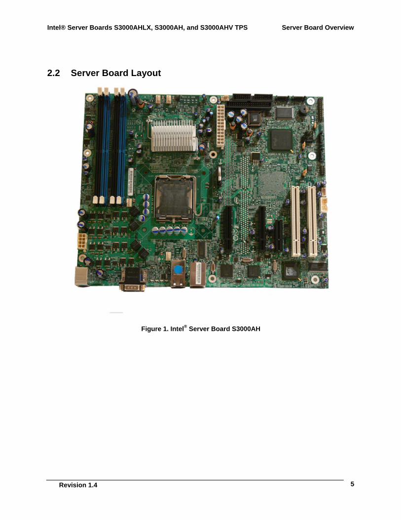
2.2 Server Board Layout
Figure 1. Intel® Server Board S3000AH
Server Board Overview Intel® Server Boards S3000AHLX, S3000AH, and S3000AHV TPS
Revision 1.2
6
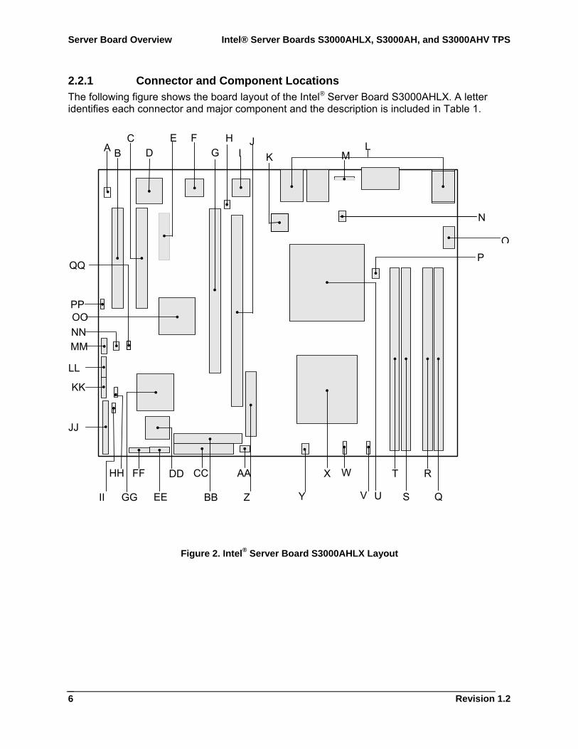
2.2.1 Connector and Component Locations The following figure shows the board layout of the Intel® Server Board S3000AHLX. A letter identifies each connector and major component and the description is included in Table 1.
Figure 2. Intel® Server Board S3000AHLX Layout
A B D C
K
E F G
HI L
O
N
P
Q
R
S
TX
U
W
VYZ
AA
BB
CC DD
EE
FF
GG
HH
II
KK
MM NN OO PP
J
JJ
LL
M
Intel® Server Boards S3000AHLX, S3000AH, and S3000AHV TPS Server Board Overview
Revision 1.4
7
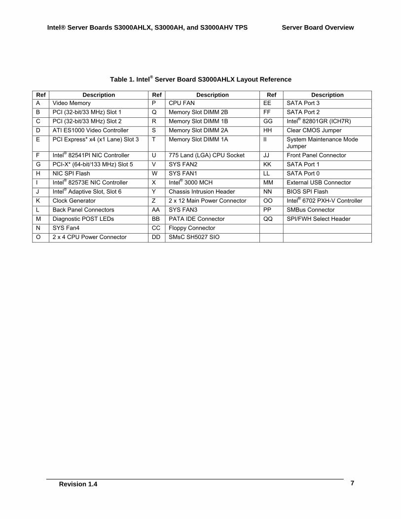
Table 1. Intel® Server Board S3000AHLX Layout Reference
Ref Description Ref Description Ref Description A Video Memory P CPU FAN EE SATA Port 3 B PCI (32-bit/33 MHz) Slot 1 Q Memory Slot DIMM 2B FF SATA Port 2 C PCI (32-bit/33 MHz) Slot 2 R Memory Slot DIMM 1B GG Intel® 82801GR (ICH7R) D ATI ES1000 Video Controller S Memory Slot DIMM 2A HH Clear CMOS Jumper E PCI Express* x4 (x1 Lane) Slot 3 T Memory Slot DIMM 1A II System Maintenance Mode
Jumper F Intel® 82541PI NIC Controller U 775 Land (LGA) CPU Socket JJ Front Panel Connector G PCI-X* (64-bit/133 MHz) Slot 5 V SYS FAN2 KK SATA Port 1 H NIC SPI Flash W SYS FAN1 LL SATA Port 0 I Intel® 82573E NIC Controller X Intel® 3000 MCH MM External USB Connector J Intel® Adaptive Slot, Slot 6 Y Chassis Intrusion Header NN BIOS SPI Flash K Clock Generator Z 2 x 12 Main Power Connector OO Intel® 6702 PXH-V Controller L Back Panel Connectors AA SYS FAN3 PP SMBus Connector M Diagnostic POST LEDs BB PATA IDE Connector QQ SPI/FWH Select Header N SYS Fan4 CC Floppy Connector O 2 x 4 CPU Power Connector DD SMsC SH5027 SIO
Server Board Overview Intel® Server Boards S3000AHLX, S3000AH, and S3000AHV TPS
Revision 1.2
8
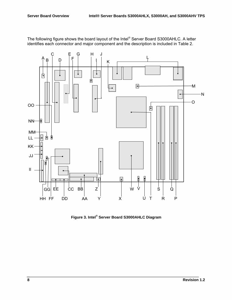
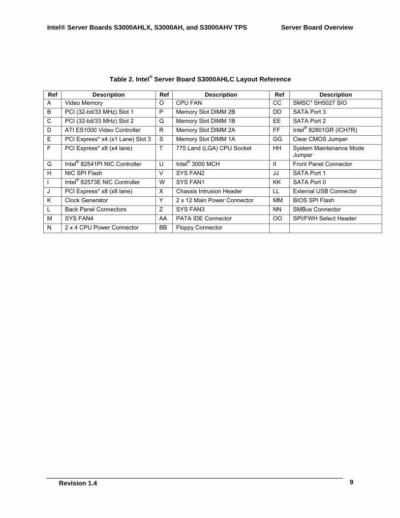
The following figure shows the board layout of the Intel® Server Board S3000AHLC. A letter identifies each connector and major component and the description is included in Table 2.
Figure 3. Intel® Server Board S3000AHLC Diagram
J
II
KK
A B D C
K
E G HI L
N
M
O
P
Q
R
SW
T
V
UXY
Z
AA
BB CC
DD
EE
FF
GG
HH
JJ
LL MM
NN
OO
F
Intel® Server Boards S3000AHLX, S3000AH, and S3000AHV TPS Server Board Overview
Revision 1.4
9
Table 2. Intel® Server Board S3000AHLC Layout Reference
Ref Description Ref Description Ref Description A Video Memory O CPU FAN CC SMSC* SH5027 SIO B PCI (32-bit/33 MHz) Slot 1 P Memory Slot DIMM 2B DD SATA Port 3 C PCI (32-bit/33 MHz) Slot 2 Q Memory Slot DIMM 1B EE SATA Port 2 D ATI ES1000 Video Controller R Memory Slot DIMM 2A FF Intel® 82801GR (ICH7R) E PCI Express* x4 (x1 Lane) Slot 3 S Memory Slot DIMM 1A GG Clear CMOS Jumper F PCI Express* x8 (x4 lane) T 775 Land (LGA) CPU Socket HH System Maintenance Mode
Jumper G Intel® 82541PI NIC Controller U Intel® 3000 MCH II Front Panel Connector H NIC SPI Flash V SYS FAN2 JJ SATA Port 1 I Intel® 82573E NIC Controller W SYS FAN1 KK SATA Port 0 J PCI Express* x8 (x8 lane) X Chassis Intrusion Header LL External USB Connector K Clock Generator Y 2 x 12 Main Power Connector MM BIOS SPI Flash L Back Panel Connectors Z SYS FAN3 NN SMBus Connector M SYS FAN4 AA PATA IDE Connector OO SPI/FWH Select Header N 2 x 4 CPU Power Connector BB Floppy Connector
Server Board Overview Intel® Server Boards S3000AHLX, S3000AH, and S3000AHV TPS
Revision 1.2
10
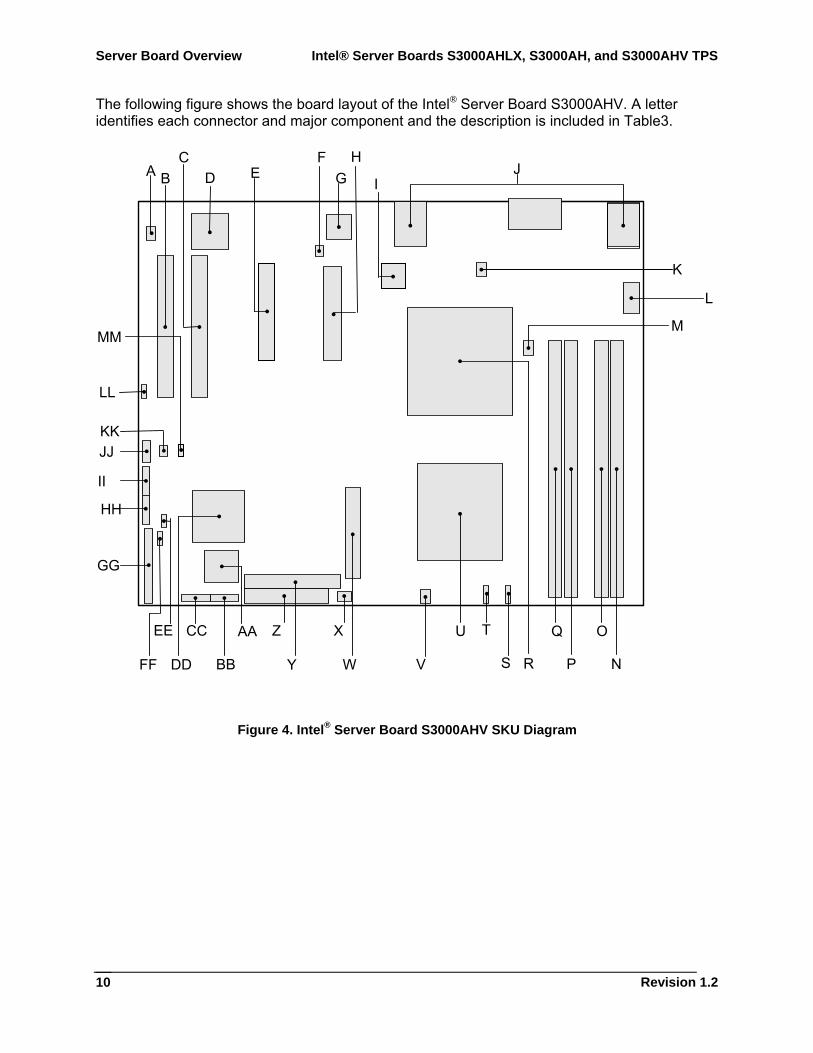
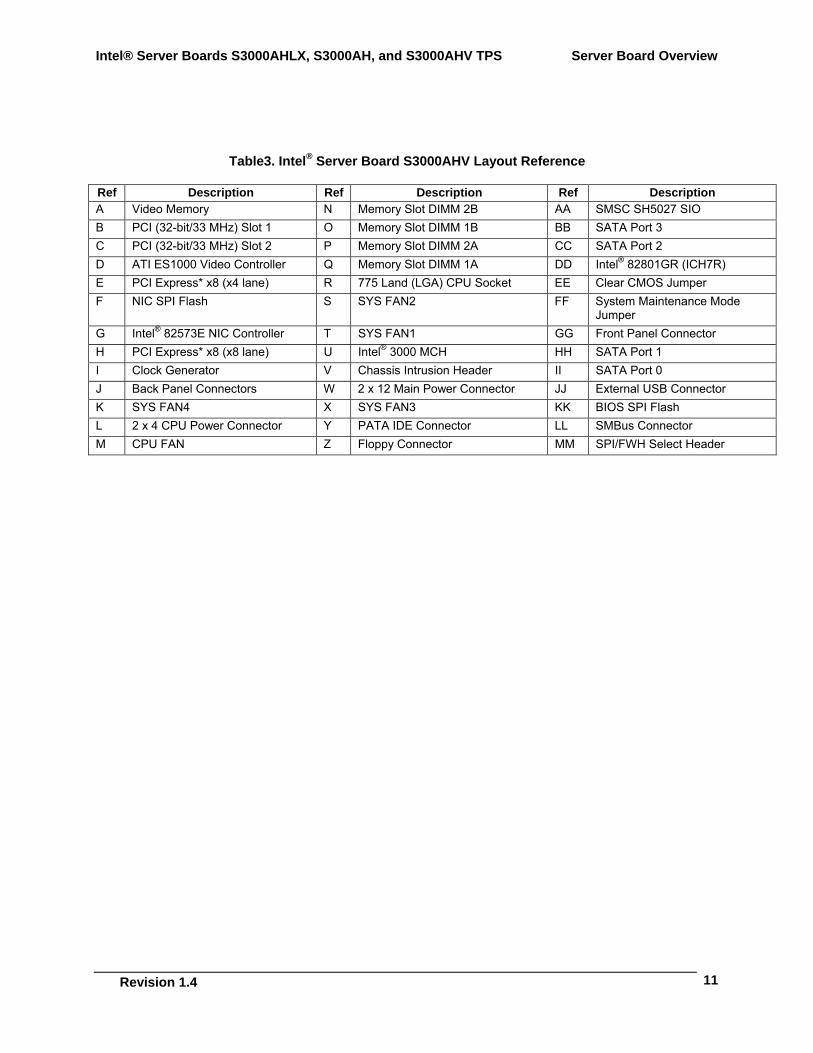
The following figure shows the board layout of the Intel® Server Board S3000AHV. A letter identifies each connector and major component and the description is included in Table3.
Figure 4. Intel® Server Board S3000AHV SKU Diagram
H
GG
II
A B D C
I
F G J
L
K
M
N
O
P
QU
R
T
SVW
X
Y
Z AA
BB
CC
DD
EE
FF
HH
JJ KK
LL
MM
E
Intel® Server Boards S3000AHLX, S3000AH, and S3000AHV TPS Server Board Overview
Revision 1.4
11
Table3. Intel® Server Board S3000AHV Layout Reference
Ref Description Ref Description Ref Description A Video Memory N Memory Slot DIMM 2B AA SMSC SH5027 SIO B PCI (32-bit/33 MHz) Slot 1 O Memory Slot DIMM 1B BB SATA Port 3 C PCI (32-bit/33 MHz) Slot 2 P Memory Slot DIMM 2A CC SATA Port 2 D ATI ES1000 Video Controller Q Memory Slot DIMM 1A DD Intel® 82801GR (ICH7R) E PCI Express* x8 (x4 lane) R 775 Land (LGA) CPU Socket EE Clear CMOS Jumper F NIC SPI Flash S SYS FAN2 FF System Maintenance Mode
Jumper G Intel® 82573E NIC Controller T SYS FAN1 GG Front Panel Connector H PCI Express* x8 (x8 lane) U Intel® 3000 MCH HH SATA Port 1 I Clock Generator V Chassis Intrusion Header II SATA Port 0 J Back Panel Connectors W 2 x 12 Main Power Connector JJ External USB Connector K SYS FAN4 X SYS FAN3 KK BIOS SPI Flash L 2 x 4 CPU Power Connector Y PATA IDE Connector LL SMBus Connector M CPU FAN Z Floppy Connector MM SPI/FWH Select Header
Server Board Overview Intel® Server Boards S3000AHLX, S3000AH, and S3000AHV TPS
Revision 1.2
12
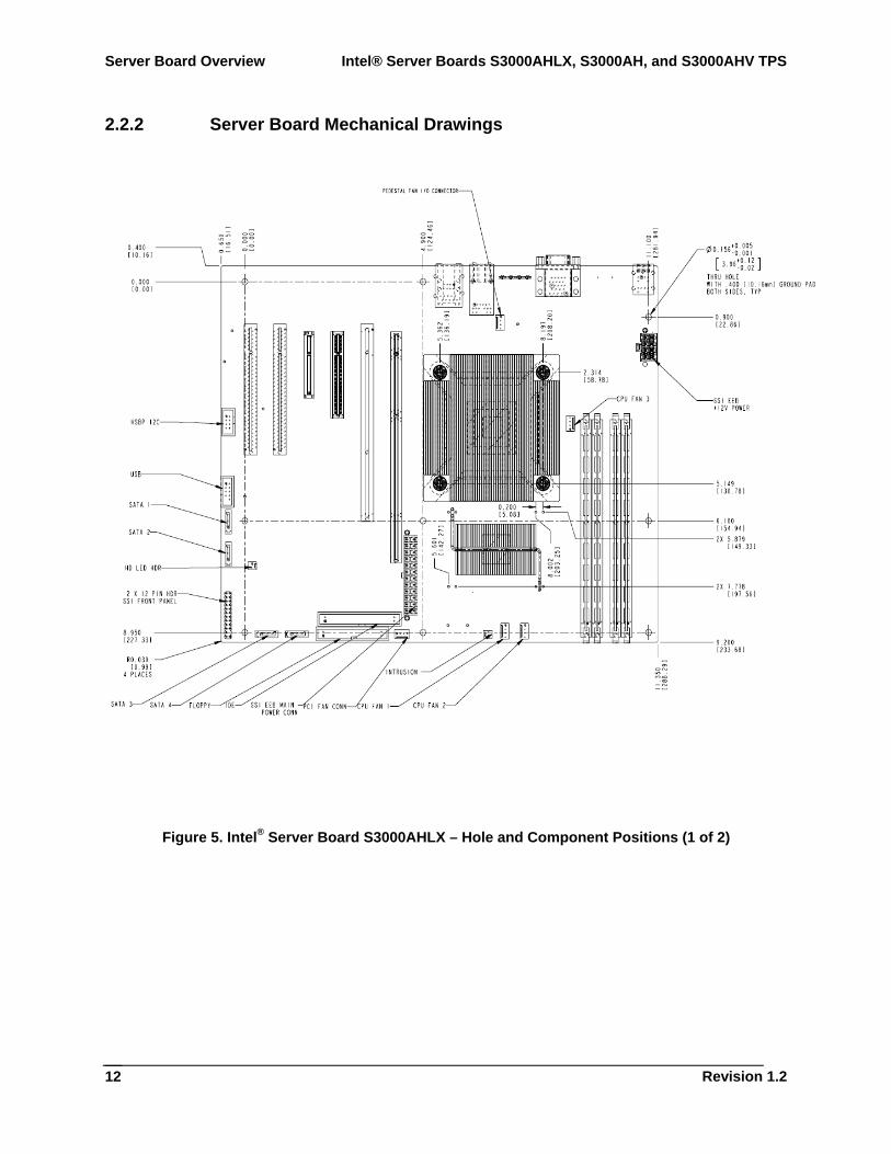
2.2.2 Server Board Mechanical Drawings
Figure 5. Intel® Server Board S3000AHLX – Hole and Component Positions (1 of 2)
Intel® Server Boards S3000AHLX, S3000AH, and S3000AHV TPS Server Board Overview
Revision 1.4
13
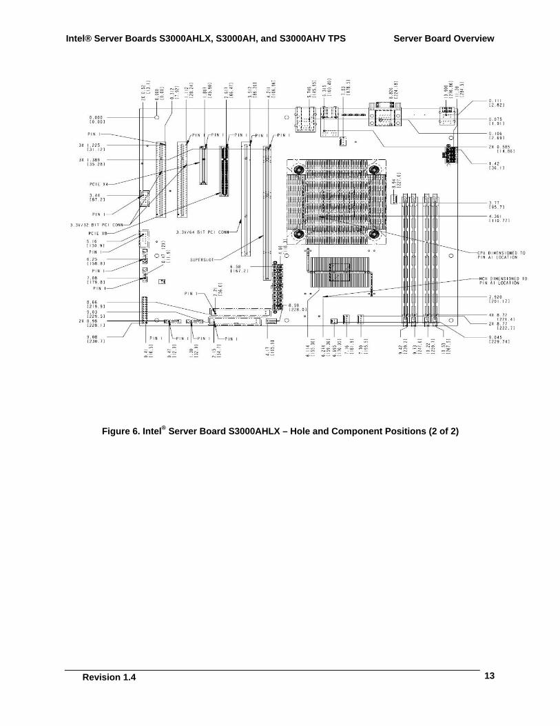
Figure 6. Intel® Server Board S3000AHLX – Hole and Component Positions (2 of 2)
Server Board Overview Intel® Server Boards S3000AHLX, S3000AH, and S3000AHV TPS
Revision 1.2
14
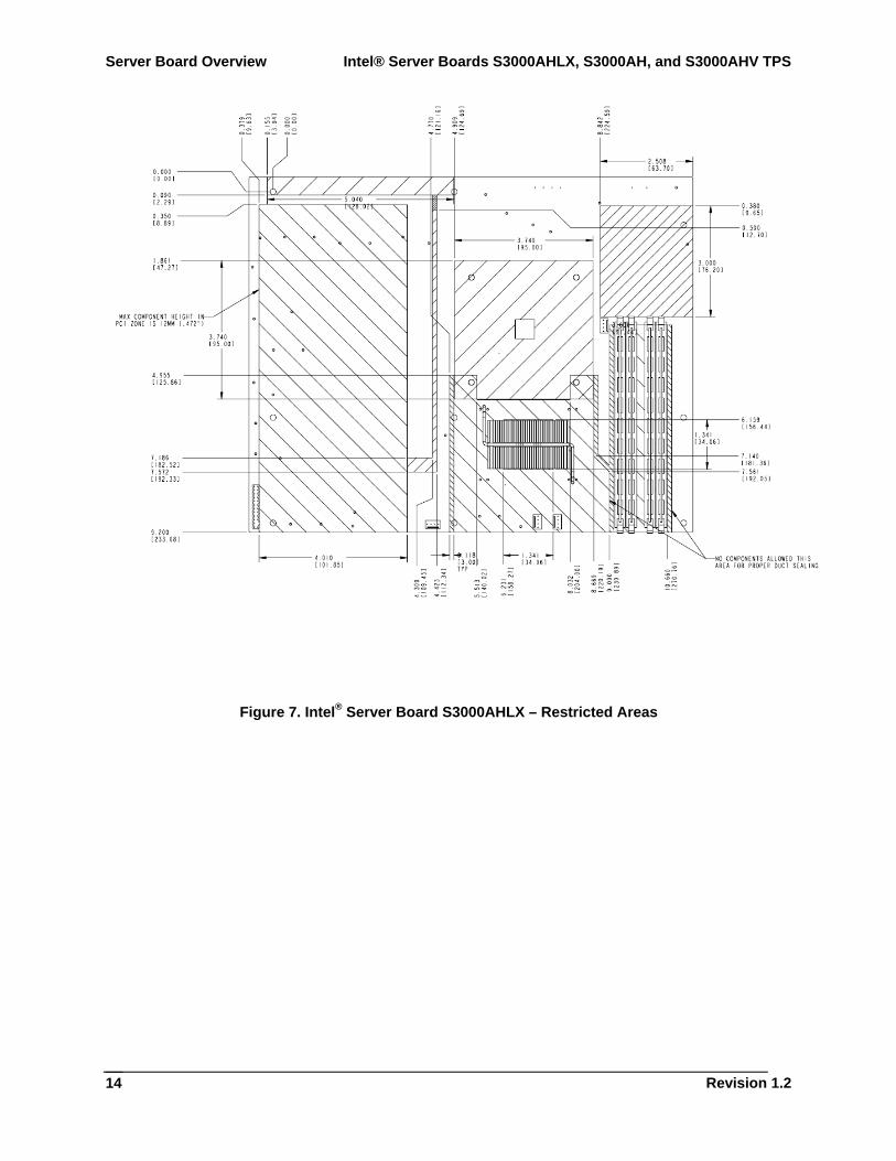
Figure 7. Intel® Server Board S3000AHLX – Restricted Areas
Intel® Server Boards S3000AHLX, S3000AH, and S3000AHV TPS Functional Architecture
Revision 1.4
15
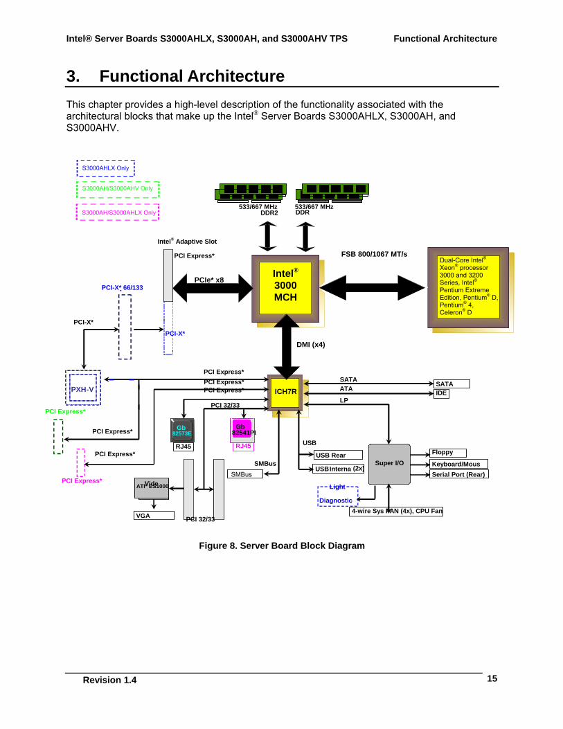
3. Functional Architecture This chapter provides a high-level description of the functionality associated with the architectural blocks that make up the Intel® Server Boards S3000AHLX, S3000AH, and S3000AHV.
Gb
Figure 8. Server Board Block Diagram
PCI Express*
ICH7R
DDR533/667 MHz
PCI 32/33
Super I/O
GbiLANGb
Tabo
-
PCI Express*
PCI-X*
Intel® Adaptive Slot
SMBus
GbiLAN Gb
TekoGbiLAN GbiLAN Gb
82573E PCI Express*
PXH - V
PCI Express*
PCI Express*
PCI Express*PCI Express*
USB
Light
Diagnostic
VGA
VideATI
VideATI* ES1000
PCI-X*
SMBus
USB Rear
USB Interna (2x)
IDE SATA
4-wire Sys FAN (4x), CPU Fan
RJ45 RJ45
LP
Floppy
Keyboard/MousSerial Port (Rear)
ATA
DDR2533/667 MHz
Intel® 3000 MCH
DMI (x4)
SATA
Dual-Core Intel® Xeon® processor 3000 and 3200 Series, Intel® Pentium Extreme Edition, Pentium® D, Pentium® 4, Celeron® D
FSB 800/1067 MT/s
PCIe* x8 - PCI-X* 66/133
PCI Express*
GbiLANGb
82541PI
PCI 32/33
S3000AHLX Only
S3000AH/S3000AHV Only
S3000AH/S3000AHLX Only
Functional Architecture Intel® Server Boards S3000AHLX, S3000AH, and S3000AHV TPS
Revision 1.2
16
3.1 Processor Sub-System The server board supports the following processors:
Dual-Core Intel® Xeon® processor 3000 series Note: The 1333 FSB processor is not supported.
Dual-Core Intel® Xeon® processor 3200 series Note: The 1333 FSB processor is not supported.
Intel® Pentium® processor Extreme Edition (S3000AHLX and S3000AH SKUs only) Intel® Pentium® D Processor Intel® Pentium® 4 Processor Intel® Celeron® D Processor
The processors built on 90nm and 65nm process technology in the 775-land package use Flip-Chip Land Grid Array (FC-LGA4) package technology, and plug into a 775-land LGA socket, referred to as the Intel® LGA775 socket.
The processors in the 775-land package are based on the same Pentium® 4 micro-architecture. They maintain compatibility with 32-bit software written for the IA-32 instruction set, while supporting 64-bit native mode operation when coupled with supported 64-bit operating systems and applications.
Note: The Intel® Celeron® D processor is not available with Intel® dual-core technology, Hyper-Threading Technology, or Intel® EM64T.
3.1.1 Processor Voltage Regulator Down (VRD) The server board has a VRD (Voltage Regulator Down) to support one processor. It is compliant with the VRD 11 DC-DC Converter Design Guide Line and provides a maximum of 125 A.
The board hardware monitors the processor VTTEN (Output enable for VTT) pin before turning on the VRD. The Power ON Logic will not turn on the VRD If the VTTEN pin of the processors is not asserted.
3.1.2 Reset Configuration Logic The BIOS determines the processor stepping and processor cache size through the CPUID instruction. The processor information is read at every system power-on.
Note: The processor speed is the processor power-on reset default value. No manual processor speed setting options exist either in the form of a BIOS setup option or jumpers.
Intel® Server Boards S3000AHLX, S3000AH, and S3000AHV TPS Functional Architecture
Revision 1.4
17
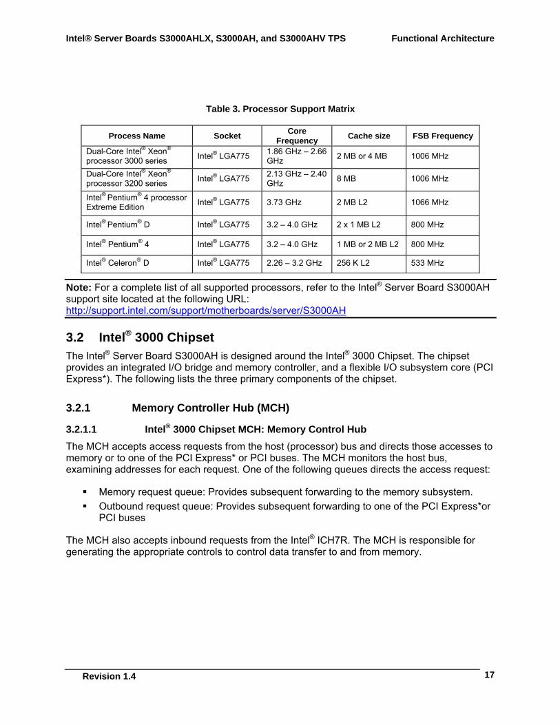
Table 3. Processor Support Matrix
Process Name Socket Core Frequency Cache size FSB Frequency
Dual-Core Intel® Xeon® processor 3000 series Intel® LGA775 1.86 GHz – 2.66
GHz 2 MB or 4 MB 1006 MHz
Dual-Core Intel® Xeon® processor 3200 series Intel® LGA775 2.13 GHz – 2.40
GHz 8 MB 1006 MHz
Intel® Pentium® 4 processor Extreme Edition Intel® LGA775 3.73 GHz 2 MB L2 1066 MHz
Intel® Pentium® D Intel® LGA775 3.2 – 4.0 GHz 2 x 1 MB L2 800 MHz
Intel® Pentium® 4 Intel® LGA775 3.2 – 4.0 GHz 1 MB or 2 MB L2 800 MHz
Intel® Celeron® D Intel® LGA775 2.26 – 3.2 GHz 256 K L2 533 MHz
Note: For a complete list of all supported processors, refer to the Intel® Server Board S3000AH support site located at the following URL: http://support.intel.com/support/motherboards/server/S3000AH
3.2 Intel® 3000 Chipset The Intel® Server Board S3000AH is designed around the Intel® 3000 Chipset. The chipset provides an integrated I/O bridge and memory controller, and a flexible I/O subsystem core (PCI Express*). The following lists the three primary components of the chipset.
3.2.1 Memory Controller Hub (MCH)
3.2.1.1 Intel® 3000 Chipset MCH: Memory Control Hub The MCH accepts access requests from the host (processor) bus and directs those accesses to memory or to one of the PCI Express* or PCI buses. The MCH monitors the host bus, examining addresses for each request. One of the following queues directs the access request:
Memory request queue: Provides subsequent forwarding to the memory subsystem. Outbound request queue: Provides subsequent forwarding to one of the PCI Express*or
PCI buses
The MCH also accepts inbound requests from the Intel® ICH7R. The MCH is responsible for generating the appropriate controls to control data transfer to and from memory.
Functional Architecture Intel® Server Boards S3000AHLX, S3000AH, and S3000AHV TPS
Revision 1.2
18
The MCH is a 1210-ball FC-BGA device and uses the proven components of the following previous generations:
Hub interface unit PCI Express* interface unit DDR2 memory interface unit
The MCH incorporates an integrated PCI Express* interface. The PCI Express interface allows the MCH and PCI Express devices to communicate directly. The MCH also increases the main memory interface bandwidth and maximum memory configuration with a 64-bit wide memory interface.
The MCH integrates the following main functions:
An integrated high performance main memory subsystem A PCI Express* bus which provides an interface to the PCI Express* devices (fully
compliant to the PCI Express* Base Specification, Rev 1.0a) A DMI which provides an interface to the Intel® ICH7R
Other features provided by the MCH include the following:
Full support of ECC on the processor bus Twelve deep in-order queue, two deep defer queue Full support of un-buffered DDR2 ECC DIMMs Support for 512 MB, 1 GB, and 2 GB DDR2 memory modules
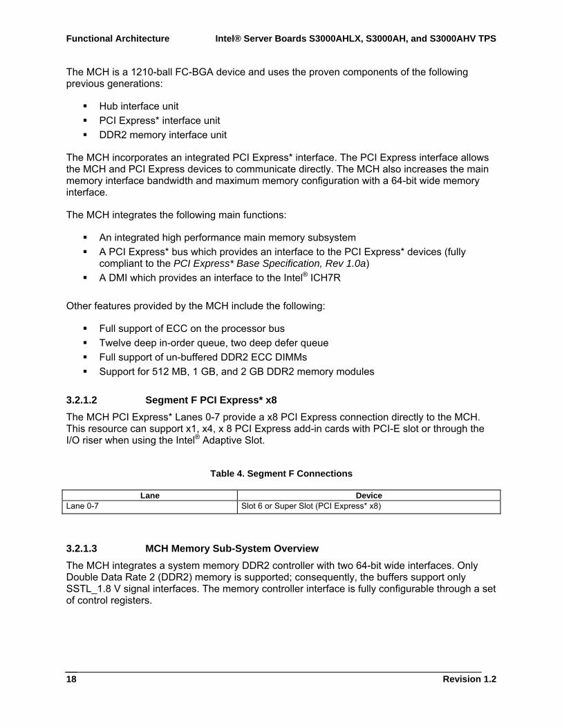
3.2.1.2 Segment F PCI Express* x8 The MCH PCI Express* Lanes 0-7 provide a x8 PCI Express connection directly to the MCH. This resource can support x1, x4, x 8 PCI Express add-in cards with PCI-E slot or through the I/O riser when using the Intel® Adaptive Slot.
Table 4. Segment F Connections
Lane Device Lane 0-7 Slot 6 or Super Slot (PCI Express* x8)
3.2.1.3 MCH Memory Sub-System Overview The MCH integrates a system memory DDR2 controller with two 64-bit wide interfaces. Only Double Data Rate 2 (DDR2) memory is supported; consequently, the buffers support only SSTL_1.8 V signal interfaces. The memory controller interface is fully configurable through a set of control registers.
Intel® Server Boards S3000AHLX, S3000AH, and S3000AHV TPS Functional Architecture
Revision 1.4
19
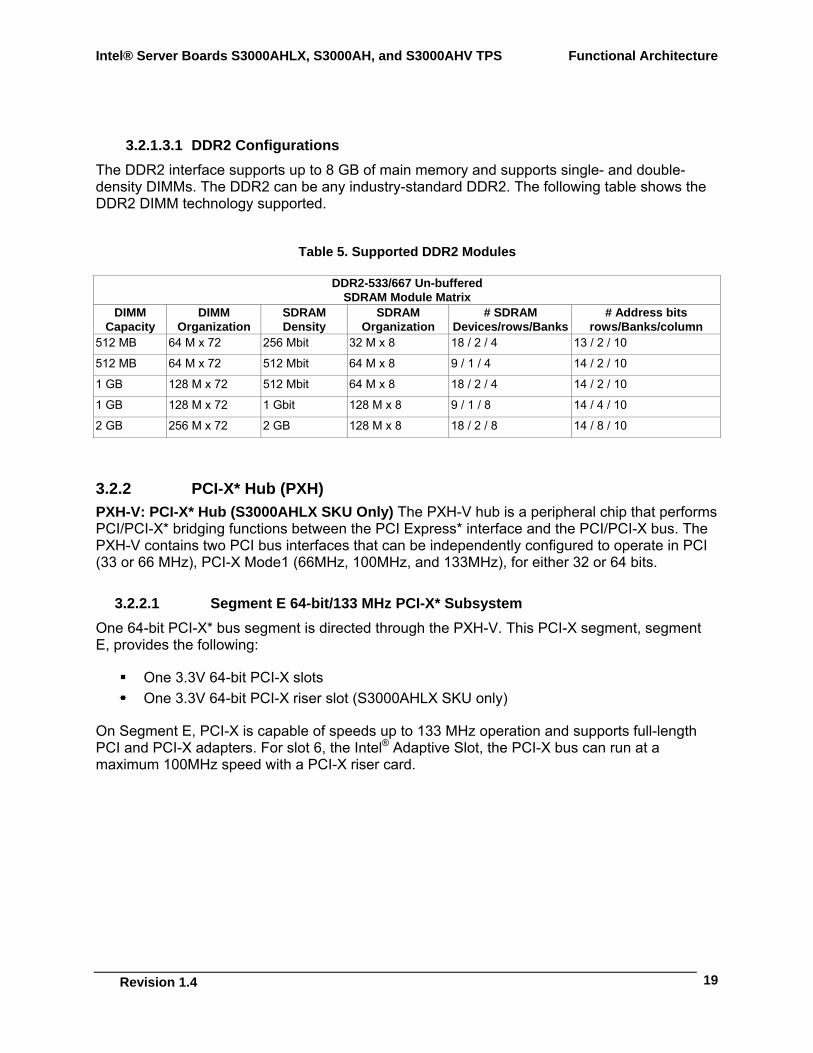
3.2.1.3.1 DDR2 Configurations The DDR2 interface supports up to 8 GB of main memory and supports single- and double-density DIMMs. The DDR2 can be any industry-standard DDR2. The following table shows the DDR2 DIMM technology supported.
Table 5. Supported DDR2 Modules
DDR2-533/667 Un-buffered SDRAM Module Matrix
DIMM Capacity
DIMM Organization
SDRAM Density
SDRAM Organization
# SDRAM Devices/rows/Banks
# Address bits rows/Banks/column
512 MB 64 M x 72 256 Mbit 32 M x 8 18 / 2 / 4 13 / 2 / 10
512 MB 64 M x 72 512 Mbit 64 M x 8 9 / 1 / 4 14 / 2 / 10
1 GB 128 M x 72 512 Mbit 64 M x 8 18 / 2 / 4 14 / 2 / 10
1 GB 128 M x 72 1 Gbit 128 M x 8 9 / 1 / 8 14 / 4 / 10
2 GB 256 M x 72 2 GB 128 M x 8 18 / 2 / 8 14 / 8 / 10
3.2.2 PCI-X* Hub (PXH) PXH-V: PCI-X* Hub (S3000AHLX SKU Only) The PXH-V hub is a peripheral chip that performs PCI/PCI-X* bridging functions between the PCI Express* interface and the PCI/PCI-X bus. The PXH-V contains two PCI bus interfaces that can be independently configured to operate in PCI (33 or 66 MHz), PCI-X Mode1 (66MHz, 100MHz, and 133MHz), for either 32 or 64 bits.
3.2.2.1 Segment E 64-bit/133 MHz PCI-X* Subsystem One 64-bit PCI-X* bus segment is directed through the PXH-V. This PCI-X segment, segment E, provides the following:
One 3.3V 64-bit PCI-X slots One 3.3V 64-bit PCI-X riser slot (S3000AHLX SKU only)
On Segment E, PCI-X is capable of speeds up to 133 MHz operation and supports full-length PCI and PCI-X adapters. For slot 6, the Intel® Adaptive Slot, the PCI-X bus can run at a maximum 100MHz speed with a PCI-X riser card.
Functional Architecture Intel® Server Boards S3000AHLX, S3000AH, and S3000AHV TPS
Revision 1.2
20
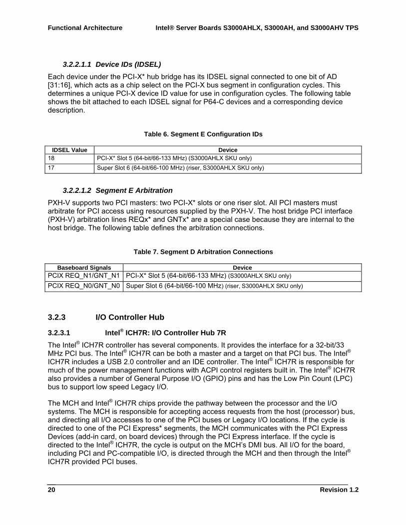
3.2.2.1.1 Device IDs (IDSEL) Each device under the PCI-X* hub bridge has its IDSEL signal connected to one bit of AD [31:16], which acts as a chip select on the PCI-X bus segment in configuration cycles. This determines a unique PCI-X device ID value for use in configuration cycles. The following table shows the bit attached to each IDSEL signal for P64-C devices and a corresponding device description.
Table 6. Segment E Configuration IDs
IDSEL Value Device 18 PCI-X* Slot 5 (64-bit/66-133 MHz) (S3000AHLX SKU only) 17 Super Slot 6 (64-bit/66-100 MHz) (riser, S3000AHLX SKU only)
3.2.2.1.2 Segment E Arbitration PXH-V supports two PCI masters: two PCI-X* slots or one riser slot. All PCI masters must arbitrate for PCI access using resources supplied by the PXH-V. The host bridge PCI interface (PXH-V) arbitration lines REQx* and GNTx* are a special case because they are internal to the host bridge. The following table defines the arbitration connections.
Table 7. Segment D Arbitration Connections
Baseboard Signals Device PCIX REQ_N1/GNT_N1 PCI-X* Slot 5 (64-bit/66-133 MHz) (S3000AHLX SKU only) PCIX REQ_N0/GNT_N0 Super Slot 6 (64-bit/66-100 MHz) (riser, S3000AHLX SKU only)
3.2.3 I/O Controller Hub
3.2.3.1 Intel® ICH7R: I/O Controller Hub 7R The Intel® ICH7R controller has several components. It provides the interface for a 32-bit/33 MHz PCI bus. The Intel® ICH7R can be both a master and a target on that PCI bus. The Intel® ICH7R includes a USB 2.0 controller and an IDE controller. The Intel® ICH7R is responsible for much of the power management functions with ACPI control registers built in. The Intel® ICH7R also provides a number of General Purpose I/O (GPIO) pins and has the Low Pin Count (LPC) bus to support low speed Legacy I/O.
The MCH and Intel® ICH7R chips provide the pathway between the processor and the I/O systems. The MCH is responsible for accepting access requests from the host (processor) bus, and directing all I/O accesses to one of the PCI buses or Legacy I/O locations. If the cycle is directed to one of the PCI Express* segments, the MCH communicates with the PCI Express Devices (add-in card, on board devices) through the PCI Express interface. If the cycle is directed to the Intel® ICH7R, the cycle is output on the MCH’s DMI bus. All I/O for the board, including PCI and PC-compatible I/O, is directed through the MCH and then through the Intel® ICH7R provided PCI buses.
Intel® Server Boards S3000AHLX, S3000AH, and S3000AHV TPS Functional Architecture
Revision 1.4
21
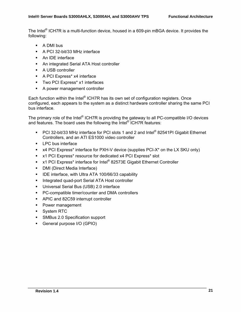
The Intel® ICH7R is a multi-function device, housed in a 609-pin mBGA device. It provides the following:
A DMI bus A PCI 32-bit/33 MHz interface An IDE interface An integrated Serial ATA Host controller A USB controller A PCI Express* x4 interface Two PCI Express* x1 interfaces A power management controller
Each function within the Intel® ICH7R has its own set of configuration registers. Once configured, each appears to the system as a distinct hardware controller sharing the same PCI bus interface.
The primary role of the Intel® ICH7R is providing the gateway to all PC-compatible I/O devices and features. The board uses the following the Intel® ICH7R features:
PCI 32-bit/33 MHz interface for PCI slots 1 and 2 and Intel® 82541PI Gigabit Ethernet Controllers, and an ATI ES1000 video controller
LPC bus interface x4 PCI Express* interface for PXH-V device (supplies PCI-X* on the LX SKU only) x1 PCI Express* resource for dedicated x4 PCI Express* slot x1 PCI Express* interface for Intel® 82573E Gigabit Ethernet Controller DMI (Direct Media Interface) IDE interface, with Ultra ATA 100/66/33 capability Integrated quad-port Serial ATA Host controller Universal Serial Bus (USB) 2.0 interface PC-compatible timer/counter and DMA controllers APIC and 82C59 interrupt controller Power management System RTC SMBus 2.0 Specification support General purpose I/O (GPIO)
Functional Architecture Intel® Server Boards S3000AHLX, S3000AH, and S3000AHV TPS
Revision 1.2
22
3.2.3.2 PCI Express*
3.2.3.2.1 PCI Express* x4 Subsystem The Intel® ICH7R supports one PCI Express* x4-lane interface that can also be configured as a single x1 or x4-lane port. The PCI Express interface allows direct connection with the PXH-V or dedicated PCI Express devices (fully compliant to the PCI Express* Base Specification, Rev 1.0a).
3.2.3.2.2 PCI Express* x1 Subsystem The Intel® ICH7R supports two x1 PCI Express* buses. One supports a dedicated x4 PCI Express slot. The other supports the Intel® 82573E Gigabit Ethernet controller.
3.2.3.3 PCI One 32-bit PCI bus segment is directed through the Intel® ICH7R Interface defined as segment A. This PCI Segment A supports two PCI connectors, one embedded Intel® 82541PI LAN controller, and one ATI ES1000 video controller. For more details on this segment, refer to chapter 3.4.1.
3.2.3.4 IDE Interface (Bus Master Capability and Synchronous DMA Mode) The Intel® ICH7R acts as a PCI-based Ultra ATA 100/66/33 IDE controller that supports programmed I/O transfers and bus master IDE transfers. The Intel® ICH7R supports one IDE channel, supporting two drives each (drives 0 and 1). The server board provides a 40-pin (2x20) IDE connector to access the IDE functionality.
The IDE interface supports Ultra ATA 100/66/33 Synchronous DMA Mode transfers on the 40-pin connector.
3.2.3.5 SATA Controller The Intel® ICH7R contains four SATA ports. The data transfer rates up to 300 Mbyte/s per port.
3.2.3.6 Compatibility Modules (DMA Controller, Timer/Counters, Interrupt Controller)
The Intel® ICH7R provides the functionality of two-cascaded 82C59 modules with the capability to handle 15 interrupts. It also supports processor system bus interrupts.
3.2.3.7 Advanced Programmable Interrupt Controller (APIC) The APICs in the Intel® ICH7R send interrupt generation and notification to the processor using messages on the front side bus.
Intel® Server Boards S3000AHLX, S3000AH, and S3000AHV TPS Functional Architecture
Revision 1.4
23
3.2.3.8 Universal Serial Bus (USB) Controller The Intel® ICH7R contains one EHCI USB 2.0 controller and can support four USB ports. The USB controller moves data between main memory and up to four USB connectors. All ports function identically and with the same bandwidth.
The server board provides two external USB ports on the rear panel of the server board. The dual-stack USB connector is located within the standard ATX I/O panel area. The Universal Serial Bus Specification, Revision 1.1, defines the external connectors.
The third/fourth USB port is optional and can be accessed by cabling from an internal 9-pin connector located on the base board to an external USB port located either in front or the rear of a given chassis.
3.2.3.9 Enhanced Power Management One of the embedded functions of the Intel® ICH7R is a power management controller that provides ACPI-compliant power management features. The server board supports sleep states S1, S4, and S5.
3.3 Memory Sub-System The server board supports up to four DIMM slots for a maximum memory capacity of 8 GB. The DIMM organization is x72, which includes eight ECC check bits. The memory interface runs at 533/667 MTs. The memory controller supports the following:
Single-bit error correction Multiple-bit error detection Memories using 512 Mbit, 1 Gbit, 2 Gbit DRAM based on memory technology
Memory can be implemented with either single-sided (one row) or double-sided (two row) DIMMs.
3.3.1 Memory Configuration The memory interface between the MCH and the DIMMs is 72-bit (ECC) wide interface.
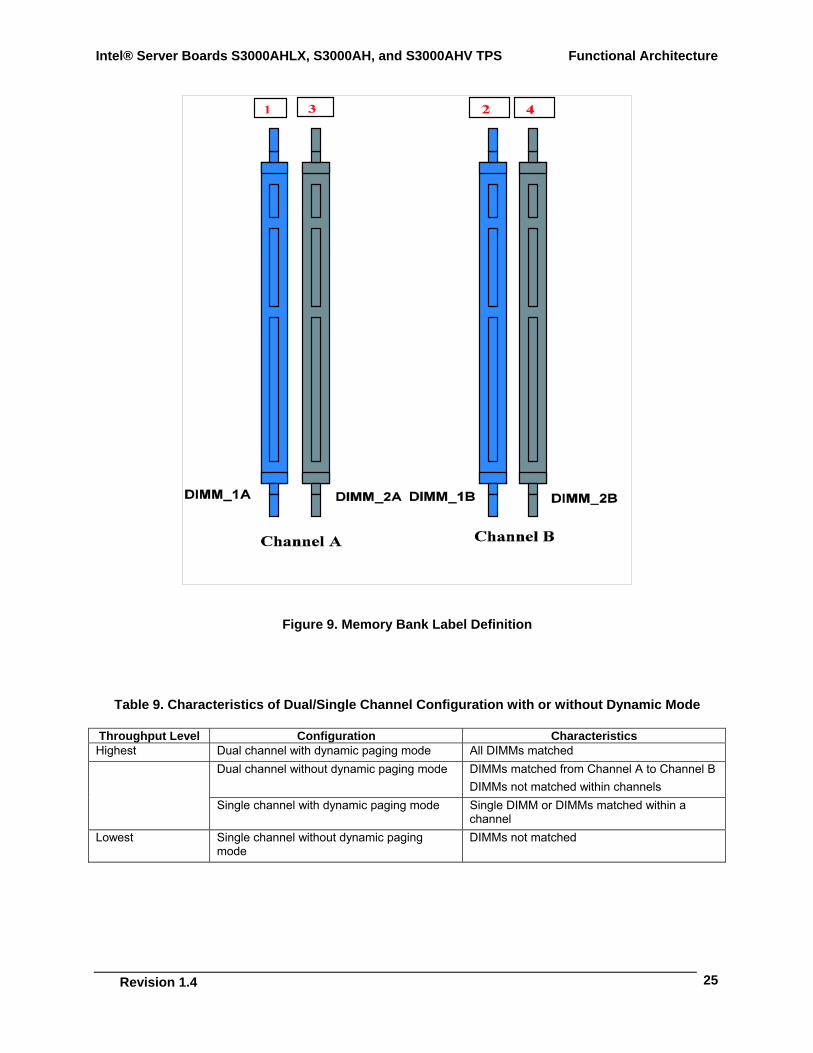
There are two banks of DIMMs, labeled 1 and 2. Bank 1 contains DIMM socket locations DIMM_1A and DIMM_2A. Bank 2 contains DIMM socket locations DIMM_1B and DIMM_2B. The sockets associated with each bank or “channel” are located next to each other and the DIMM socket identifiers are marked on the server board silkscreen, near the DIMM socket. Bank 1 is associated with Memory Channel A while Bank 2 is associated with Memory Channel B. When only two DIMM modules are used, the population order must be DIMM_1A, DIMM_1B to ensure dual channel operating mode.
Functional Architecture Intel® Server Boards S3000AHLX, S3000AH, and S3000AHV TPS
Revision 1.2
24
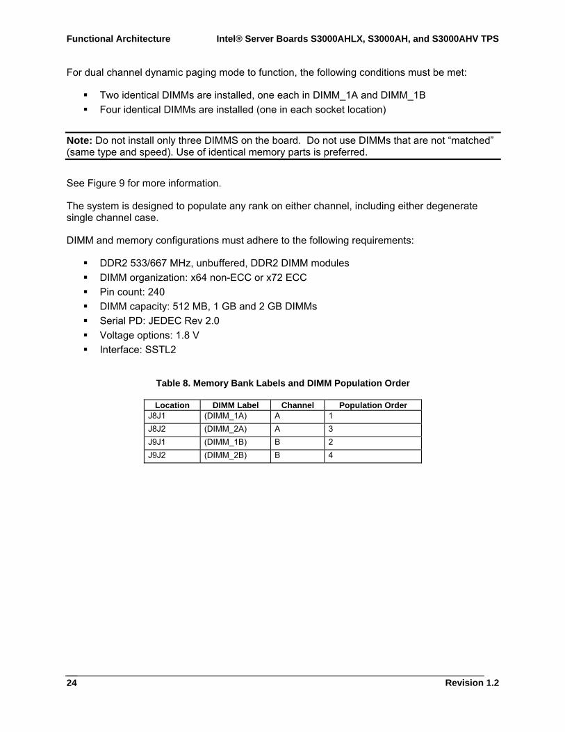
For dual channel dynamic paging mode to function, the following conditions must be met:
Two identical DIMMs are installed, one each in DIMM_1A and DIMM_1B Four identical DIMMs are installed (one in each socket location)
Note: Do not install only three DIMMS on the board. Do not use DIMMs that are not “matched” (same type and speed). Use of identical memory parts is preferred.
See Figure 9 for more information.
The system is designed to populate any rank on either channel, including either degenerate single channel case.
DIMM and memory configurations must adhere to the following requirements:
DDR2 533/667 MHz, unbuffered, DDR2 DIMM modules DIMM organization: x64 non-ECC or x72 ECC Pin count: 240 DIMM capacity: 512 MB, 1 GB and 2 GB DIMMs Serial PD: JEDEC Rev 2.0 Voltage options: 1.8 V Interface: SSTL2
Table 8. Memory Bank Labels and DIMM Population Order
Location DIMM Label Channel Population Order J8J1 (DIMM_1A) A 1 J8J2 (DIMM_2A) A 3 J9J1 (DIMM_1B) B 2 J9J2 (DIMM_2B) B 4
Intel® Server Boards S3000AHLX, S3000AH, and S3000AHV TPS Functional Architecture
Revision 1.4
25
Figure 9. Memory Bank Label Definition
Table 9. Characteristics of Dual/Single Channel Configuration with or without Dynamic Mode
Throughput Level Configuration Characteristics Highest Dual channel with dynamic paging mode All DIMMs matched
Dual channel without dynamic paging mode DIMMs matched from Channel A to Channel B DIMMs not matched within channels
Single channel with dynamic paging mode Single DIMM or DIMMs matched within a channel
Lowest Single channel without dynamic paging mode
DIMMs not matched
Functional Architecture Intel® Server Boards S3000AHLX, S3000AH, and S3000AHV TPS
Revision 1.2
26
3.3.2 Memory DIMM Support The board supports unbuffered (not registered) DDR2 533/667 MHz ECC or Non-ECC DIMMs operating at 533/667MT/s. This board only supports DIMMs tested and qualified by Intel or a designated memory test vendor. A list of qualified DIMMs is available at http://support.intel.com/support/motherboards/server/S3000AH. Although all DIMMs are supported by design, the board only supports fully qualified DIMMs.
The minimum supported DIMM size is 512 MB. Therefore, the minimum main memory configuration is 1 x 512 MB or 512 MB. The largest size DIMM supported is 2 GB and as such, the maximum main memory configuration is 8 GB implemented by 4 x 2 GB DIMMs.
Supports unbuffered DDR2 533/667 MHz compliant, ECC x8 and Non-ECC x8 or x16 memory DIMMs.
Detects and corrects ECC single-bit errors (SBE). Detects multiple-bit errors (MBE). The maximum memory capacity is 8 GB via four 2 GB DIMM modules. The minimum memory capacity is 512 MB via a single 512 MB DIMM module.
3.4 I/O Sub-System
3.4.1 PCI Subsystem The primary I/O buses for the server board are five independent PCI bus segments providing PCI, PCI Express* and PCI-X* resources (S3000AHLX SKU only). The PCI buses comply with the PCI Local Bus Specification, Rev 2.3.
PCI Segments A, B, C, and D are directed through the Intel® ICH7R. PCI Segment E is independently configured to PXH-V that is through Intel® ICH7R by the PCI Express* x4 interface. The PCI Express X8 interface directs PCI Segment F through the MCH. The following table lists the characteristics of the three PCI bus segments.
Table 10. PCI Bus Segment Characteristics
PCI Bus Segment Voltage Width Speed Type PCI I/O Card Slots
A 3.3V 32 bits 33 MHz PCI 32 Slot 1, Slot 2, NIC 2, video B 3.3V 1 lane 2.5 GHz X1 PCI Express* Slot 3, X4 physical connector C 3.3V 1 lane 2.5 GHz X1 PCI Express* NIC 1 D 3.3V 4 lane 2.5 GHz X4 PCI Express* Slot 4, PXH, X8 physical connectorE 3.3V 64 bits 66/100/133 MHz PCI-64 Slot 5, Slot 6 through riser card F 3.3V 8 lanes 2.5 GHz x8 PCI Express* Slot 6, X8 physical connector
3.4.1.1 P32-A: 32-bit, 33-MHz PCI Subsystem The Intel® ICH7R provides a Legacy 32-bit PCI subsystem and acts as the central resource on this PCI interface. P32-A supports the following embedded devices and connectors:
Intel® Server Boards S3000AHLX, S3000AH, and S3000AHV TPS Functional Architecture
Revision 1.4
27
One Intel® 82541PI Fast Ethernet Controller One ATI ES1000 Video Controller Two slots capable of supporting full-length PCI add-in cards operating at 33 MHz
3.4.1.1.1 Device IDs (IDSEL) Each device under the PCI hub bridge has its IDSEL signal connected to one bit of AD (31:16), which acts as a chip select on the PCI bus segment in configuration cycles. This determines a unique PCI device ID value for use in configuration cycles. The following table shows the Segment A IDSEL signal and bits and the corresponding device description.
Table 11. Segment A Configuration IDs
IDSEL Value Device 21 Intel® 82541PI LAN (NIC2) 20 ATI ES1000 Video Controller 17 PCI Slot 1(32-bit/33 MHz) 16 PCI slot 2(32-bit/33 MHz)
3.4.1.1.2 Segment A Arbitration PCI Segment A supports two PCI devices: the Intel® ICH7R and one PCI bus master (NIC). All PCI masters must arbitrate for PCI access, using resources supplied by the Intel® ICH7R. The host bridge PCI interface (ICH7R) arbitration lines REQx* and GNTx* are a special case in that they are internal to the host bridge. The following table defines the arbitration connections.
Table 12. Segment A Arbitration Connections
Baseboard Signals Device PCI REQ_N5/GNT_N5 Intel® 82541PI LAN (NIC2) PCI REQ_N1/GNT_N1 PCI Slot 1(32-bit/33 MHz) PCI REQ_N0/GNT_N0 PCI Slot 2(32-bit/33 MHz)
Functional Architecture Intel® Server Boards S3000AHLX, S3000AH, and S3000AHV TPS
Revision 1.2
28
3.4.1.2 PCI Interface for Video subsystem The Intel® ICH7R uses a 32/33MHz PCI bus to connect to the server board graphics subsystem.
3.4.2 Interrupt Routing The board interrupt architecture accommodates both PC-compatible PIC mode and APIC mode interrupts through the use of the integrated I/O APICs in the Intel® ICH7R.
3.4.2.1 Legacy Interrupt Routing For PC-compatible mode, the Intel® ICH7R provides two 82C59-compatible interrupt controllers. The two controllers are cascaded with interrupt levels 8-15 entering on level 2 of the primary interrupt controller (standard PC configuration). The processor receives a single interrupt signal, which the processor responds to for servicing. The Intel® ICH7R contains configuration registers that define which interrupt source logically maps to I/O APIC INTx pins.
The Intel® ICH7R handles both PCI and IRQ interrupts. The Intel® ICH7R translates these to the APIC bus. The numbers in the following table indicate the Intel® ICH7R PCI interrupt input pin to which the associated device interrupt (INTA, INTB, INTC, INTD, INTE, INTF, INTG, INTH for PCI bus and PXIRQ0, PXIRQ1, PXIRQ2, and PXIRQ3 for PCI-X* bus) is connected. The Intel® ICH7R I/O APIC exists on the I/O APIC bus with the processor.
Table 13. PCI AND PCI-X* Interrupt Routing/Sharing
Interrupt INT A INT B INT C INT D Intel® 82541PI LAN (NIC2) PIRQB ATI ES1000 Video Controller PIRQC PCI Slot 1 (PCI 32-bit/33 MHz) PIRQG PIRQF PIRQE PIRQH PCI Slot 2 (PCI 32-bit/33 MHz) PIRQF PIRQG PIRQH PIRQE PCI-X* Slot 5 (64-bit/133 MHz) (LX SKU only) PXIRQ5 PXIRQ6 PXIRQ7 PXIRQ4 PCI-X* Slot 6 (64-bit/133 MHz) (Riser, LX SKU only)
PXIRQ0 PXIRQ1 PXIRQ2 PXIRQ3
3.4.2.2 APIC Interrupt Routing For APIC mode, the server board interrupt architecture incorporates three Intel® I/O APIC devices to manage and broadcast interrupts to local APICs in each processor. The Intel® I/O APICs monitor each interrupt on each PCI device including PCI slots in addition to the ISA compatibility interrupts IRQ (0-15).
When an interrupt occurs, a three-wire serial interface sends a message corresponding to the interrupt to the local APICs. The APIC bus minimizes interrupt latency time for compatibility interrupt sources. The I/O APICs can also supply greater than 16 interrupt levels to the processor(s). This APIC bus consists of an APIC clock and two bi-directional data lines.
Intel® Server Boards S3000AHLX, S3000AH, and S3000AHV TPS Functional Architecture
Revision 1.4
29
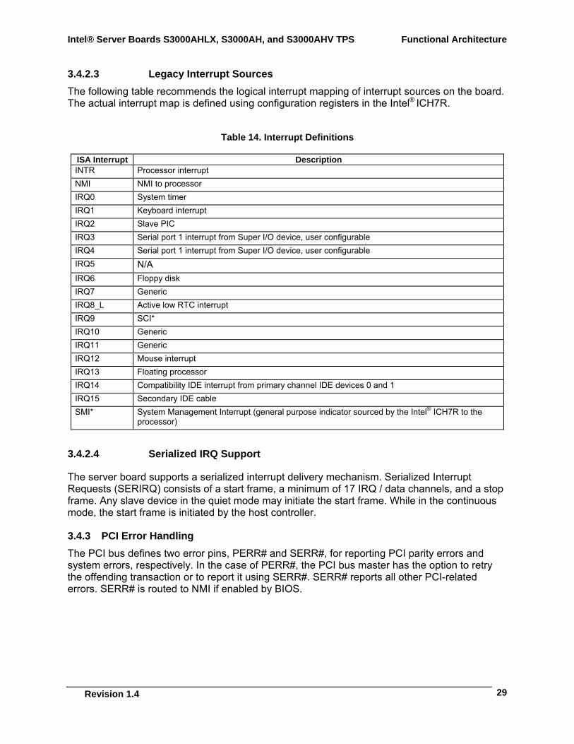
3.4.2.3 Legacy Interrupt Sources The following table recommends the logical interrupt mapping of interrupt sources on the board. The actual interrupt map is defined using configuration registers in the Intel® ICH7R.
Table 14. Interrupt Definitions
ISA Interrupt Description INTR Processor interrupt NMI NMI to processor IRQ0 System timer IRQ1 Keyboard interrupt IRQ2 Slave PIC IRQ3 Serial port 1 interrupt from Super I/O device, user configurable IRQ4 Serial port 1 interrupt from Super I/O device, user configurable IRQ5 N/A IRQ6 Floppy disk IRQ7 Generic IRQ8_L Active low RTC interrupt IRQ9 SCI* IRQ10 Generic IRQ11 Generic IRQ12 Mouse interrupt IRQ13 Floating processor IRQ14 Compatibility IDE interrupt from primary channel IDE devices 0 and 1 IRQ15 Secondary IDE cable SMI* System Management Interrupt (general purpose indicator sourced by the Intel® ICH7R to the
processor)
3.4.2.4 Serialized IRQ Support
The server board supports a serialized interrupt delivery mechanism. Serialized Interrupt Requests (SERIRQ) consists of a start frame, a minimum of 17 IRQ / data channels, and a stop frame. Any slave device in the quiet mode may initiate the start frame. While in the continuous mode, the start frame is initiated by the host controller.
3.4.3 PCI Error Handling The PCI bus defines two error pins, PERR# and SERR#, for reporting PCI parity errors and system errors, respectively. In the case of PERR#, the PCI bus master has the option to retry the offending transaction or to report it using SERR#. SERR# reports all other PCI-related errors. SERR# is routed to NMI if enabled by BIOS.
Functional Architecture Intel® Server Boards S3000AHLX, S3000AH, and S3000AHV TPS
Revision 1.2
30
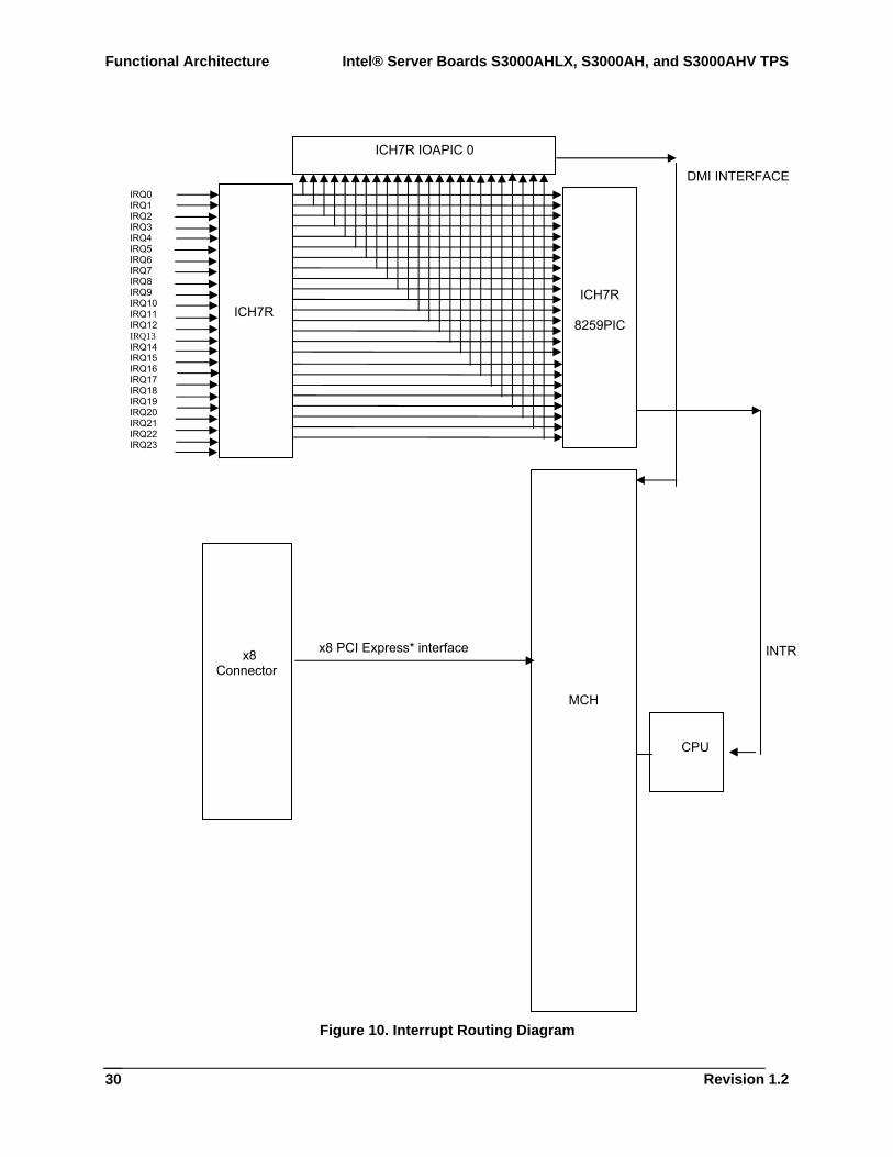
Figure 10. Interrupt Routing Diagram
IRQ0 IRQ1 IRQ2 IRQ3 IRQ4 IRQ5 IRQ6 IRQ7 IRQ8 IRQ9 IRQ10 IRQ11 IRQ12 IRQ13 IRQ14 IRQ15 IRQ16 IRQ17 IRQ18 IRQ19 IRQ20 IRQ21 IRQ22 IRQ23
ICH7R IOAPIC 0
ICH7R
MCH
x8 PCI Express* interface
ICH7R
8259PIC
x8 Connector
CPU
INTR
DMI INTERFACE

Intel® Server Boards S3000AHLX, S3000AH, and S3000AHV TPS Functional Architecture
Revision 1.4
31
Figure 11. Intel® ICH7R Interrupt Routing Diagram
PIRQB#
PIRQD#
PIRQC#
PIRQE#
PIRQF#
PIRQG#
PIRQH#
PIRQA#
Super I/O Timer
Keyboard
Serial Port2/ISA
Serial Port1/ISA
ISA
Floppy/ISA
ISA
RTC
SCI/ISA
ISA
ISA
Mouse/ISA
Coprocessor Error
P IDE/ISA
Not Used
Cascade
Serialized IRQ
Interface
SERIRQ
ICH
7R Interrupt
Routing
PCI Interface
SERIRQ
ATI ES1000 Video
Slot 1 and 2 INTB
Intel® 82541PI NIC
N/A
N/ASlot 1 and 2 INTC
Slot 1 and 2 INTA
Slot 1 and 2 INTD
Functional Architecture Intel® Server Boards S3000AHLX, S3000AH, and S3000AHV TPS
Revision 1.2
32
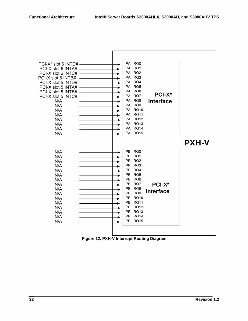
Figure 12. PXH-V Interrupt Routing Diagram
PA IRQ0PA IRQ1PA IRQ2PA IRQ3PA IRQ4PA IRQ5PA IRQ6PA IRQ7PA IRQ8PA IRQ9PA IRQ10PA IRQ11PA IRQ12PA IRQ13PA IRQ14PA IRQ15
PB IRQ0PB IRQ1PB IRQ2PB IRQ3PB IRQ4PB IRQ5PB IRQ6PB IRQ7PB IRQ8PB IRQ9PB IRQ10PB IRQ11PB IRQ12PB IRQ13PB IRQ14PB IRQ15
PXH-V
PCI-X* Interface
PCI-X* Interface
PCI-X* slot 6 INTD# PCI-X slot 6 INTA# PCI-X slot 6 INTC# PCI-X slot 6 INTB# PCI-X slot 5 INTD# PCI-X slot 5 INTA# PCI-X slot 5 INTB# PCI-X slot 5 INTC#
N/A N/A N/A N/A N/A N/A N/A N/A
N/A N/A N/A N/A N/A N/A N/A N/A N/A N/A N/A N/A N/A N/A N/A N/A
Intel® Server Boards S3000AHLX, S3000AH, and S3000AHV TPS Functional Architecture
Revision 1.4
33
3.5 On-Board Components
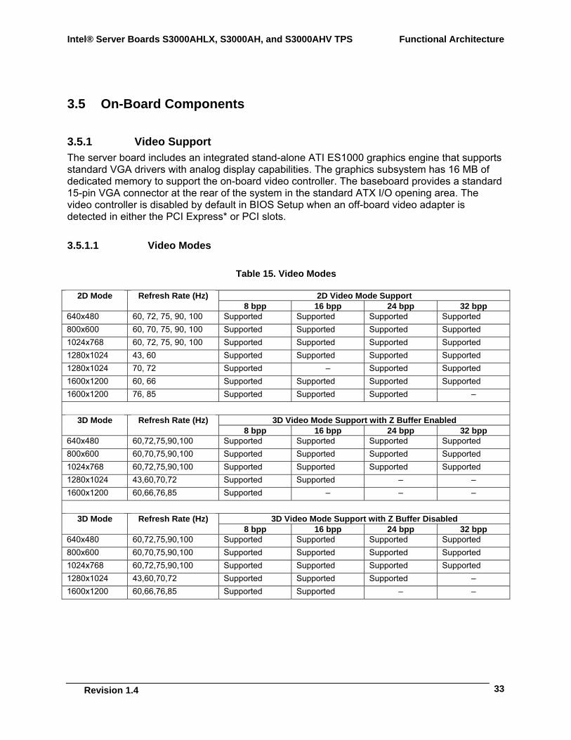
3.5.1 Video Support The server board includes an integrated stand-alone ATI ES1000 graphics engine that supports standard VGA drivers with analog display capabilities. The graphics subsystem has 16 MB of dedicated memory to support the on-board video controller. The baseboard provides a standard 15-pin VGA connector at the rear of the system in the standard ATX I/O opening area. The video controller is disabled by default in BIOS Setup when an off-board video adapter is detected in either the PCI Express* or PCI slots.
3.5.1.1 Video Modes
Table 15. Video Modes
2D Video Mode Support 2D Mode Refresh Rate (Hz) 8 bpp 16 bpp 24 bpp 32 bpp
640x480 60, 72, 75, 90, 100 Supported Supported Supported Supported 800x600 60, 70, 75, 90, 100 Supported Supported Supported Supported 1024x768 60, 72, 75, 90, 100 Supported Supported Supported Supported 1280x1024 43, 60 Supported Supported Supported Supported 1280x1024 70, 72 Supported – Supported Supported 1600x1200 60, 66 Supported Supported Supported Supported 1600x1200 76, 85 Supported Supported Supported –
3D Video Mode Support with Z Buffer Enabled 3D Mode Refresh Rate (Hz) 8 bpp 16 bpp 24 bpp 32 bpp
640x480 60,72,75,90,100 Supported Supported Supported Supported 800x600 60,70,75,90,100 Supported Supported Supported Supported 1024x768 60,72,75,90,100 Supported Supported Supported Supported 1280x1024 43,60,70,72 Supported Supported – – 1600x1200 60,66,76,85 Supported – – –
3D Video Mode Support with Z Buffer Disabled 3D Mode Refresh Rate (Hz) 8 bpp 16 bpp 24 bpp 32 bpp
640x480 60,72,75,90,100 Supported Supported Supported Supported 800x600 60,70,75,90,100 Supported Supported Supported Supported 1024x768 60,72,75,90,100 Supported Supported Supported Supported 1280x1024 43,60,70,72 Supported Supported Supported – 1600x1200 60,66,76,85 Supported Supported – –
Functional Architecture Intel® Server Boards S3000AHLX, S3000AH, and S3000AHV TPS
Revision 1.2
34
3.5.1.2 Dual Video The on-board graphics controller does not support dual video mode. When an add-in video card is populated, the on-board video controller is automatically disabled.
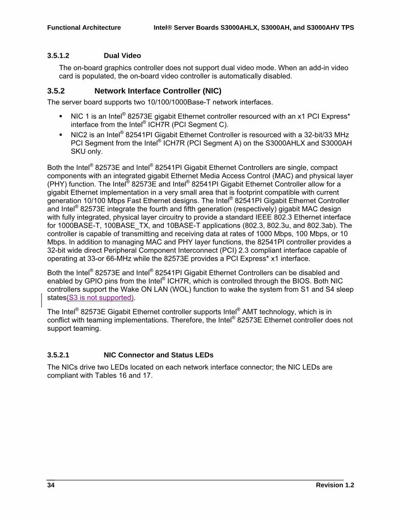
3.5.2 Network Interface Controller (NIC) The server board supports two 10/100/1000Base-T network interfaces.
NIC 1 is an Intel® 82573E gigabit Ethernet controller resourced with an x1 PCI Express* interface from the Intel® ICH7R (PCI Segment C).
NIC2 is an Intel® 82541PI Gigabit Ethernet Controller is resourced with a 32-bit/33 MHz PCI Segment from the Intel® ICH7R (PCI Segment A) on the S3000AHLX and S3000AH SKU only.
Both the Intel® 82573E and Intel® 82541PI Gigabit Ethernet Controllers are single, compact components with an integrated gigabit Ethernet Media Access Control (MAC) and physical layer (PHY) function. The Intel® 82573E and Intel® 82541PI Gigabit Ethernet Controller allow for a gigabit Ethernet implementation in a very small area that is footprint compatible with current generation 10/100 Mbps Fast Ethernet designs. The Intel® 82541PI Gigabit Ethernet Controller and Intel® 82573E integrate the fourth and fifth generation (respectively) gigabit MAC design with fully integrated, physical layer circuitry to provide a standard IEEE 802.3 Ethernet interface for 1000BASE-T, 100BASE_TX, and 10BASE-T applications (802.3, 802.3u, and 802.3ab). The controller is capable of transmitting and receiving data at rates of 1000 Mbps, 100 Mbps, or 10 Mbps. In addition to managing MAC and PHY layer functions, the 82541PI controller provides a 32-bit wide direct Peripheral Component Interconnect (PCI) 2.3 compliant interface capable of operating at 33-or 66-MHz while the 82573E provides a PCI Express* x1 interface.
Both the Intel® 82573E and Intel® 82541PI Gigabit Ethernet Controllers can be disabled and enabled by GPIO pins from the Intel® ICH7R, which is controlled through the BIOS. Both NIC controllers support the Wake ON LAN (WOL) function to wake the system from S1 and S4 sleep states(S3 is not supported).
The Intel® 82573E Gigabit Ethernet controller supports Intel® AMT technology, which is in conflict with teaming implementations. Therefore, the Intel® 82573E Ethernet controller does not support teaming.
3.5.2.1 NIC Connector and Status LEDs The NICs drive two LEDs located on each network interface connector; the NIC LEDs are compliant with Tables 16 and 17.
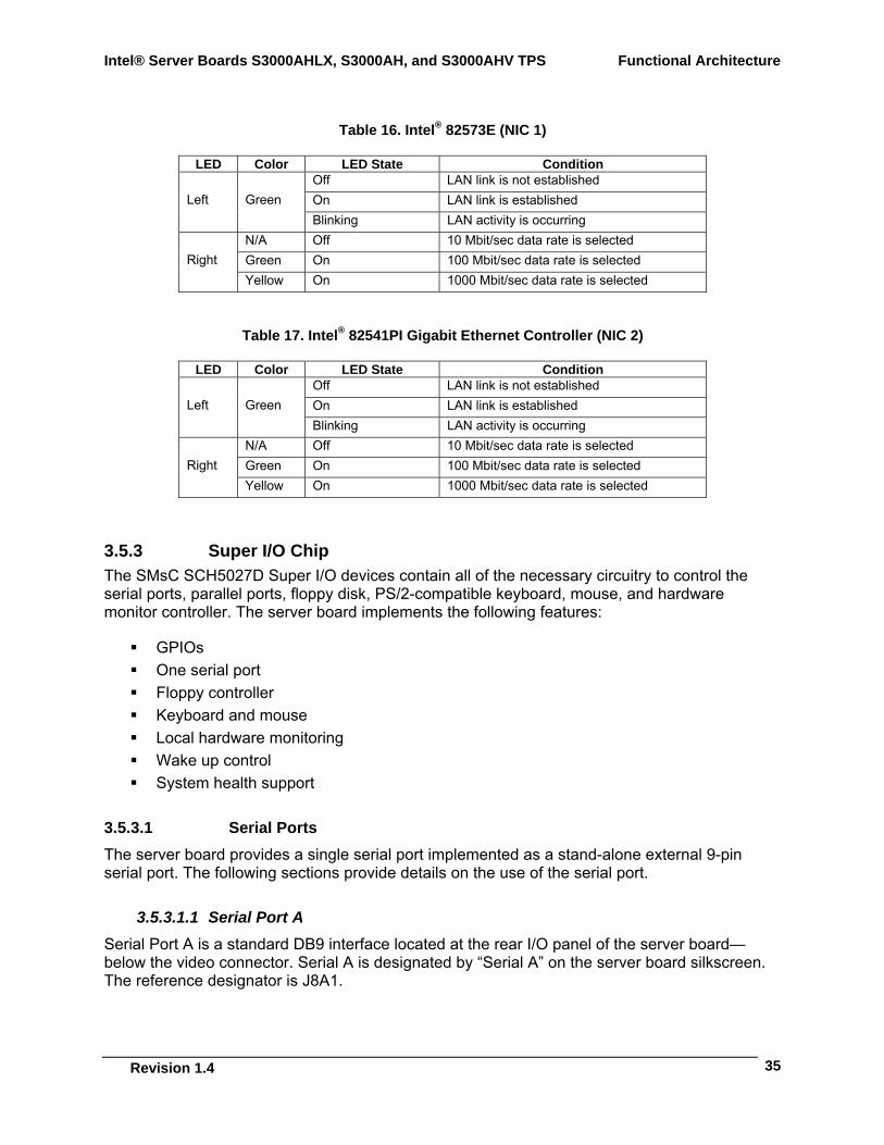
Intel® Server Boards S3000AHLX, S3000AH, and S3000AHV TPS Functional Architecture
Revision 1.4
35
Table 16. Intel® 82573E (NIC 1)
LED Color LED State Condition Off LAN link is not established On LAN link is established Left Green Blinking LAN activity is occurring
N/A Off 10 Mbit/sec data rate is selected Green On 100 Mbit/sec data rate is selected Right Yellow On 1000 Mbit/sec data rate is selected
Table 17. Intel® 82541PI Gigabit Ethernet Controller (NIC 2)
LED Color LED State Condition Off LAN link is not established On LAN link is established Left Green Blinking LAN activity is occurring
N/A Off 10 Mbit/sec data rate is selected Green On 100 Mbit/sec data rate is selected Right Yellow On 1000 Mbit/sec data rate is selected
3.5.3 Super I/O Chip The SMsC SCH5027D Super I/O devices contain all of the necessary circuitry to control the serial ports, parallel ports, floppy disk, PS/2-compatible keyboard, mouse, and hardware monitor controller. The server board implements the following features:
GPIOs One serial port Floppy controller Keyboard and mouse Local hardware monitoring Wake up control System health support
3.5.3.1 Serial Ports The server board provides a single serial port implemented as a stand-alone external 9-pin serial port. The following sections provide details on the use of the serial port.
3.5.3.1.1 Serial Port A Serial Port A is a standard DB9 interface located at the rear I/O panel of the server board—below the video connector. Serial A is designated by “Serial A” on the server board silkscreen. The reference designator is J8A1.
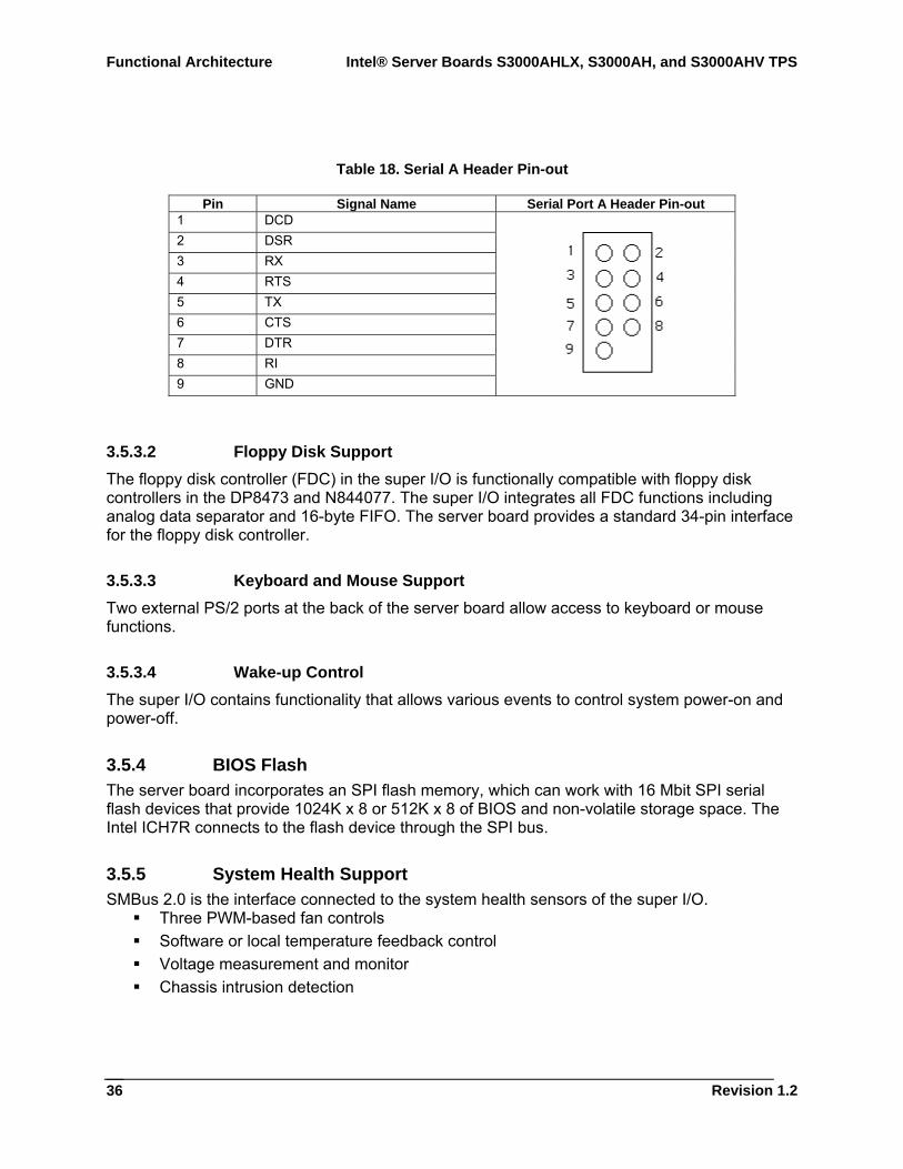
Functional Architecture Intel® Server Boards S3000AHLX, S3000AH, and S3000AHV TPS
Revision 1.2
36
Table 18. Serial A Header Pin-out
Pin Signal Name Serial Port A Header Pin-out 1 DCD 2 DSR 3 RX 4 RTS 5 TX 6 CTS 7 DTR 8 RI 9 GND
3.5.3.2 Floppy Disk Support The floppy disk controller (FDC) in the super I/O is functionally compatible with floppy disk controllers in the DP8473 and N844077. The super I/O integrates all FDC functions including analog data separator and 16-byte FIFO. The server board provides a standard 34-pin interface for the floppy disk controller.
3.5.3.3 Keyboard and Mouse Support Two external PS/2 ports at the back of the server board allow access to keyboard or mouse functions.
3.5.3.4 Wake-up Control The super I/O contains functionality that allows various events to control system power-on and power-off.
3.5.4 BIOS Flash The server board incorporates an SPI flash memory, which can work with 16 Mbit SPI serial flash devices that provide 1024K x 8 or 512K x 8 of BIOS and non-volatile storage space. The Intel ICH7R connects to the flash device through the SPI bus.
3.5.5 System Health Support SMBus 2.0 is the interface connected to the system health sensors of the super I/O.
Three PWM-based fan controls Software or local temperature feedback control Voltage measurement and monitor Chassis intrusion detection
Intel® Server Boards S3000AHLX, S3000AH, and S3000AHV TPS Functional Architecture
Revision 1.4
37
3.6 Replacing the Back-Up Battery The lithium battery on the server board powers the RTC for up to ten years in the absence of power. When the battery starts to weaken, it loses voltage, and the server settings stored in CMOS RAM in the RTC (for example, the date and time) may be wrong. Contact your customer service representative or dealer for a list of approved devices.
WARNING
There is a danger of explosion if the battery is incorrectly replaced. Replace only with the same or equivalent type recommended by the equipment manufacturer. Discard used batteries according to manufacturer’s instructions.
ADVARSEL!
Lithiumbatteri - Eksplosionsfare ved fejlagtig håndtering. Udskiftning må kun ske med batteri af samme fabrikat og type. Levér det brugte batteri tilbage til leverandøren.
ADVARSEL
Lithiumbatteri - Eksplosjonsfare. Ved utskifting benyttes kun batteri som anbefalt av apparatfabrikanten. Brukt batteri returneres apparatleverandøren.
VARNING
Explosionsfara vid felaktigt batteribyte. Använd samma batterityp eller en ekvivalent typ som rekommenderas av apparattillverkaren. Kassera använt batteri enligt fabrikantens instruktion.
VAROITUS
Paristo voi räjähtää, jos se on virheellisesti asennettu. Vaihda paristo ainoastaan laitevalmistajan suosittelemaan tyyppiin. Hävitä käytetty paristo valmistajan ohjeiden mukaisesti.
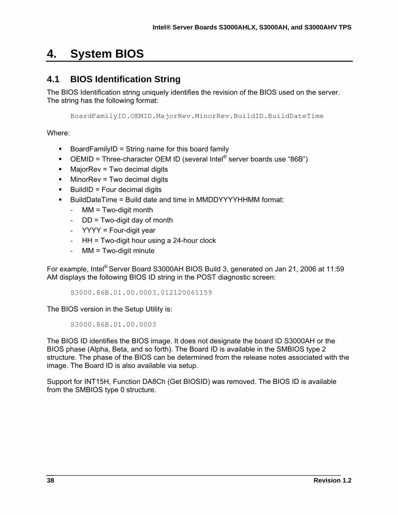
Intel® Server Boards S3000AHLX, S3000AH, and S3000AHV TPS
Revision 1.2
38
4. System BIOS
4.1 BIOS Identification String The BIOS Identification string uniquely identifies the revision of the BIOS used on the server. The string has the following format:
BoardFamilyID.OEMID.MajorRev.MinorRev.BuildID.BuildDateTime Where:
BoardFamilyID = String name for this board family OEMID = Three-character OEM ID (several Intel® server boards use “86B”) MajorRev = Two decimal digits MinorRev = Two decimal digits BuildID = Four decimal digits BuildDateTime = Build date and time in MMDDYYYYHHMM format:
- MM = Two-digit month - DD = Two-digit day of month - YYYY = Four-digit year - HH = Two-digit hour using a 24-hour clock - MM = Two-digit minute
For example, Intel® Server Board S3000AH BIOS Build 3, generated on Jan 21, 2006 at 11:59 AM displays the following BIOS ID string in the POST diagnostic screen:
S3000.86B.01.00.0003.012120061159
The BIOS version in the Setup Utility is:
S3000.86B.01.00.0003
The BIOS ID identifies the BIOS image. It does not designate the board ID S3000AH or the BIOS phase (Alpha, Beta, and so forth). The Board ID is available in the SMBIOS type 2 structure. The phase of the BIOS can be determined from the release notes associated with the image. The Board ID is also available via setup.
Support for INT15H, Function DA8Ch (Get BIOSID) was removed. The BIOS ID is available from the SMBIOS type 0 structure.
Intel® Server Boards S3000AHLX, S3000AH, and S3000AHV TPS System BIOS
Revision 1.4
39
4.2 Logo or Diagnostic Window The Logo or Diagnostic window may take one of two forms. In quiet boot mode, a logo splash screen appears. In verbose mode, a system summary and diagnostic screen is displayed. The default is to display the logo in quiet boot mode. If no logo is present in the flash ROM, or if quiet boot mode is disabled in the system configuration, the summary and diagnostic screen is displayed.
The diagnostic screen consists of the following information:
BIOS ID Total memory detected (total size of all installed DIMMs) Processor information (Intel branded string, speed, and number of physical processors
identified) Types of keyboards detected if plugged in (PS/2 and/or USB) Types of mouse devices detected if plugged in (PS/2 and/or USB)
4.3 BIOS Setup Utility The BIOS Setup utility is a text-based utility that allows the user to configure the system and view current settings and environment information for the platform devices. The Setup utility controls built-in devices in the platform.
The BIOS Setup interface consists of a number of pages or screens. Each page contains information or links to other pages. The first page in Setup displays a list of general categories as links. These links lead to pages containing specific category’s configuration.
The following sections describe the look and behavior for platform Setup.
4.3.1 Operation BIOS Setup is functional via console redirection over various terminal emulation standards. This may limit some functionality for compatibility (for example color usage, some keys or key sequences, or support of pointing devices). The BIOS is only available in English.
4.3.1.1 Setup Page Layout The setup page layout has different functional areas. Each area displays on the screen and has a specific function. The following table lists and describes each functional area.
Intel® Server Boards S3000AHLX, S3000AH, and S3000AHV TPS
Revision 1.2
40
Table 19. BIOS Setup Page Layout
Functional Area Description Title Bar The title bar is located at the top of the screen and displays the title of the current
form (page). It can also display navigational information. Setup Item List The Setup Item List is a set of controllable and informational items. Each item in the
list occupies the left and center columns in the middle of the screen. The left column, the "Setup Item", is the subject of the item. The middle column, the "Option", contains an informational value or choices. A Setup Item may also be a hyperlink used to navigate form sets (pages). A Setup Item only occupies the “Setup Item” column when it is a hyperlink.
Item Specific Help Area The Item Specific Help Area is located on the right side of the screen and contains help text for the highlighted Setup Item. Help information includes the meaning and usage of the item, allowable values, effects of the options, and so forth.
Keyboard Command Bar The Keyboard Command Bar is located at the bottom right of the screen and continuously displays help for keyboard special keys and navigation keys. The keyboard command bar is context-sensitive—it displays keys relevant to the current page and mode.
Status Bar The Status Bar occupies the bottom line of the screen. This line displays the BIOS ID.
4.3.1.2 Entering BIOS Setup Start the BIOS Setup by pressing <F2> when the OEM or Intel logo appears.
When Quiet Boot is disabled, the message “Press <F2> to enter setup” displays on the diagnostics screen.
4.3.1.3 Keyboard Commands The bottom right portion of the Setup screen provides a list of commands used to navigate through the Setup utility. These commands are available at all times.
Each Setup menu page contains a number of features. Each feature is associated with a value field except those used for informative purposes. This field contains user-selectable parameters. Depending on the security option chosen and loaded by the password, a menu feature’s value may or may not be changeable. If a value is non-changeable, the feature’s value field is inaccessible. It appears “grayed out.”

Intel® Server Boards S3000AHLX, S3000AH, and S3000AHV TPS System BIOS
Revision 1.4
41
The Keyboard Command Bar supports the following:
Table 20. BIOS Setup: Keyboard Command Bar
Key Option Description <Enter> Execute
Command The <Enter> key activates the sub-menus when the selected feature is a sub-menu, or to display a pick list if a selected option has a value field, or to select a sub-field for multi-valued features like time and date. If a pick list is displayed, the <Enter> key will select the currently highlighted item, undo the pick list, and return the focus to the parent menu.
<Esc> Exit The <Esc> key provides a mechanism for backing out of any field. This key will undo pressing the Enter key. Using the <Esc> key while editing any field or selecting features of a menu causes the parent menu to reload. Using the <Esc> key in any sub-menu causes the parent menu to reload. Using the <Esc> key in any major menu causes the exit confirmation window to load and the user can choose whether to discard changes. If “No” is selected and the <Enter> key is pressed, or if the <Esc> key is pressed, the user is returned to where he/she was before the <Esc> key was pressed, without affecting any existing settings. If “Yes” is selected and the <Enter> key is pressed, the setup is closed and the main BIOS System Options Menu screen appears.
↑ Select Item Use the up arrow to select the previous value in a pick list, or the previous option in a menu. Press the <Enter> key to activate the selected item.
↓ Select Item Use the down arrow to select the next value in a menu list, or a value field’s pick list. Press <Enter> to activate the selected item.
↔ Select Menu Use the left and right arrow keys to move between the major menu pages. The keys have no effect in a sub-menu or pick list.
<Tab> Select Field Use the <Tab> key to move between fields. For example, use <Tab> to move from hours to minutes in the time item in the main menu.
- Change Value Use the minus key on the keypad to change the value of the current item to the previous value. This key scrolls through the values in the associated pick list without displaying the full list.
+ Change Value Use the plus key on the keypad to change the value of the current menu item to the next value. This key scrolls through the values in the associated pick list without displaying the full list. On 106-key Japanese keyboards, the plus key has a different scan code than the plus key on the other keyboard, but it will have the same effect.
<F9> Setup Defaults Pressing <F9> causes the following message o appear:
Load Optimized defaults? (Y/N) If the <Y> key is pressed, all Setup fields are set to their default values. If the <N> or <Esc> keys are pressed, the user is returned to where they were before <F9> was pressed without affecting any existing field values
<F10> Save and Exit Pressing <F10> causes the following message to appear:
Save Configuration and Reset? (Y/N) If the <Y> key is pressed, all changes are saved and Setup is exited. If the <N> or <Esc> keys are pressed, the user is returned to where they were before <F10> was pressed without affecting any existing field values.
4.3.1.4 Menu Selection Bar The Menu Selection Bar is located at the top of the screen. It displays the major menu selections available to the user.
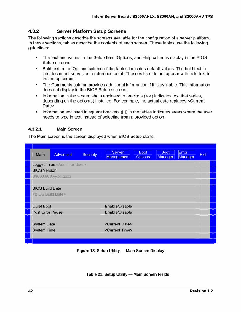
Intel® Server Boards S3000AHLX, S3000AH, and S3000AHV TPS
Revision 1.2
42
4.3.2 Server Platform Setup Screens The following sections describe the screens available for the configuration of a server platform. In these sections, tables describe the contents of each screen. These tables use the following guidelines:
The text and values in the Setup Item, Options, and Help columns display in the BIOS Setup screens.
Bold text in the Options column of the tables indicates default values. The bold text in this document serves as a reference point. These values do not appear with bold text in the setup screen.
The Comments column provides additional information if it is available. This information does not display in the BIOS Setup screens.
Information in the screen shots enclosed in brackets (< >) indicates text that varies, depending on the option(s) installed. For example, the actual date replaces <Current Date>.
Information enclosed in square brackets ([ ]) in the tables indicates areas where the user needs to type in text instead of selecting from a provided option.
4.3.2.1 Main Screen The Main screen is the screen displayed when BIOS Setup starts.
Main Advanced Security Server
Management Boot
Options Boot
Manager Error Manager Exit
Logged in as <Admin or User> BIOS Version S3000.86B.yy.xx.zzzz BIOS Build Date
<BIOS Build Date>
Quiet Boot Enable/Disable Post Error Pause Enable/Disable System Date <Current Date> System Time <Current Time>
Figure 13. Setup Utility — Main Screen Display
Table 21. Setup Utility — Main Screen Fields
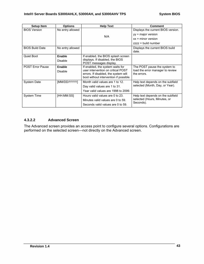
Intel® Server Boards S3000AHLX, S3000AH, and S3000AHV TPS System BIOS
Revision 1.4
43
Setup Item Options Help Text Comment BIOS Version No entry allowed
N/A
Displays the current BIOS version. yy = major version xx = minor version zzzz = build number
BIOS Build Date No entry allowed Displays the current BIOS build date.
Quiet Boot Enable Disable
If enabled, the BIOS splash screen displays. If disabled, the BIOS POST messages display.
POST Error Pause Enable Disable
If enabled, the system waits for user intervention on critical POST errors. If disabled, the system will boot without intervention if possible.
The POST pause the system to load the error manager to review the errors.
System Date [MM/DD/YYYY] Month valid values are 1 to 12. Day valid values are 1 to 31. Year valid values are 1998 to 2099.
Help text depends on the subfield selected (Month, Day, or Year).
System Time [HH:MM:SS] Hours valid values are 0 to 23. Minutes valid values are 0 to 59. Seconds valid values are 0 to 59.
Help text depends on the subfield selected (Hours, Minutes, or Seconds).
4.3.2.2 Advanced Screen The Advanced screen provides an access point to configure several options. Configurations are performed on the selected screen—not directly on the Advanced screen.
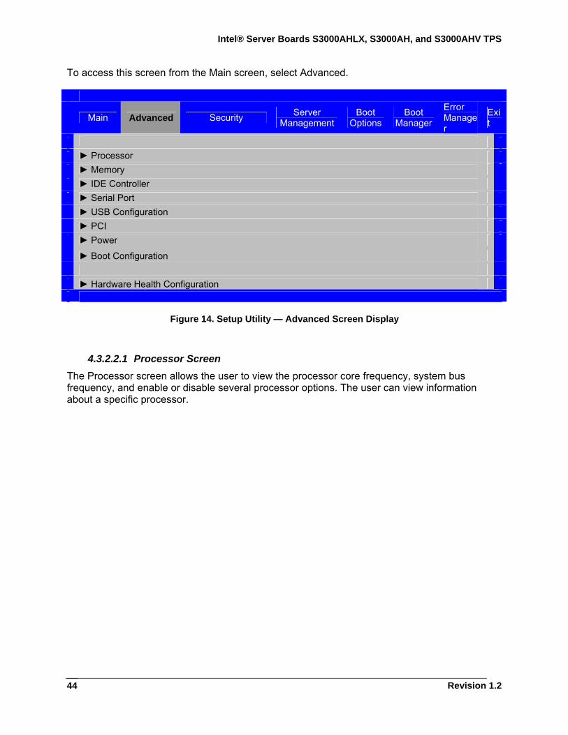
Intel® Server Boards S3000AHLX, S3000AH, and S3000AHV TPS
Revision 1.2
44
To access this screen from the Main screen, select Advanced.
Main Advanced Security Server
Management Boot
Options Boot
Manager Error Manager
Exit
► Processor ► Memory ► IDE Controller ► Serial Port ► USB Configuration ► PCI ► Power
► Boot Configuration ► Hardware Health Configuration
Figure 14. Setup Utility — Advanced Screen Display
4.3.2.2.1 Processor Screen The Processor screen allows the user to view the processor core frequency, system bus frequency, and enable or disable several processor options. The user can view information about a specific processor.
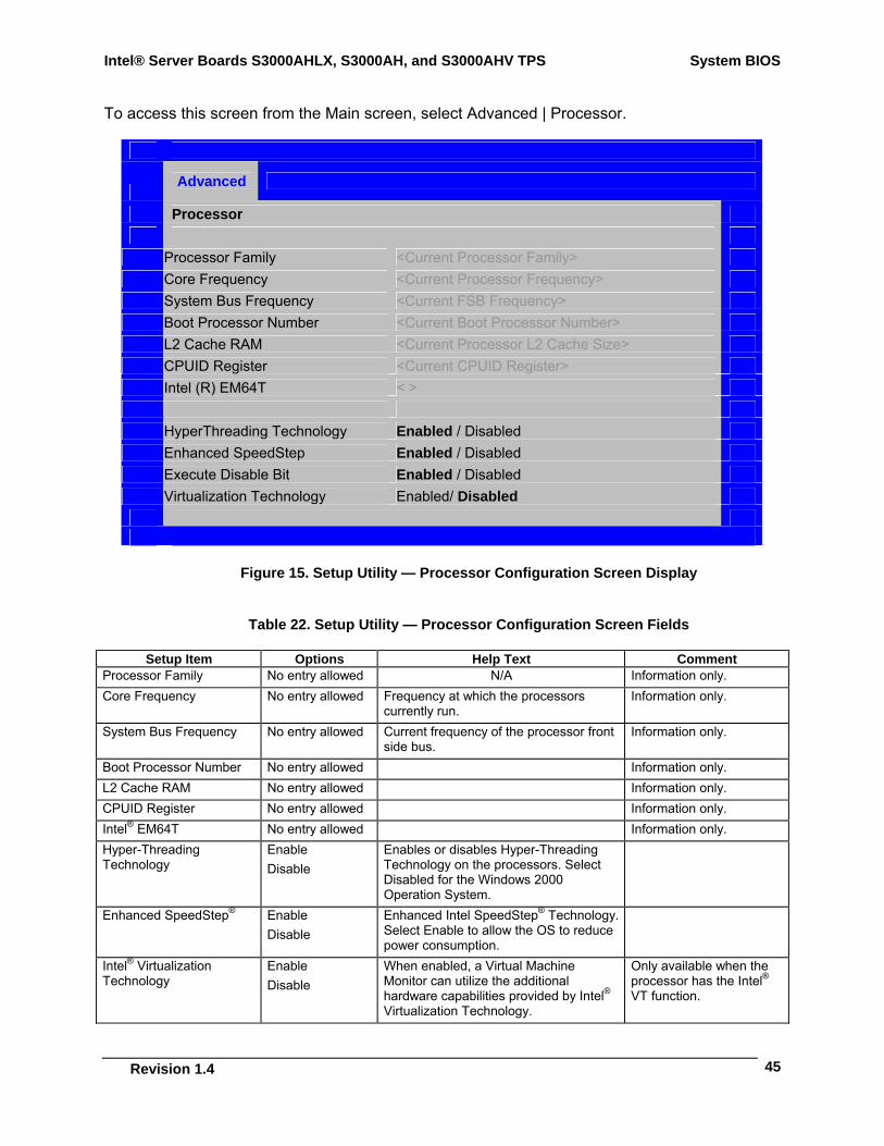
Intel® Server Boards S3000AHLX, S3000AH, and S3000AHV TPS System BIOS
Revision 1.4
45
To access this screen from the Main screen, select Advanced | Processor.
Advanced
Processor
Processor Family <Current Processor Family> Core Frequency <Current Processor Frequency> System Bus Frequency <Current FSB Frequency> Boot Processor Number <Current Boot Processor Number> L2 Cache RAM <Current Processor L2 Cache Size> CPUID Register <Current CPUID Register> Intel (R) EM64T < > HyperThreading Technology Enabled / Disabled Enhanced SpeedStep Enabled / Disabled Execute Disable Bit Enabled / Disabled Virtualization Technology Enabled/ Disabled
Figure 15. Setup Utility — Processor Configuration Screen Display
Table 22. Setup Utility — Processor Configuration Screen Fields
Setup Item Options Help Text Comment Processor Family No entry allowed N/A Information only. Core Frequency No entry allowed Frequency at which the processors
currently run. Information only.
System Bus Frequency No entry allowed Current frequency of the processor front side bus.
Information only.
Boot Processor Number No entry allowed Information only. L2 Cache RAM No entry allowed Information only. CPUID Register No entry allowed Information only. Intel® EM64T No entry allowed Information only. Hyper-Threading Technology
Enable Disable
Enables or disables Hyper-Threading Technology on the processors. Select Disabled for the Windows 2000 Operation System.
Enhanced SpeedStep® Enable Disable
Enhanced Intel SpeedStep® Technology. Select Enable to allow the OS to reduce power consumption.
Intel® Virtualization Technology
Enable Disable
When enabled, a Virtual Machine Monitor can utilize the additional hardware capabilities provided by Intel® Virtualization Technology.
Only available when the processor has the Intel® VT function.
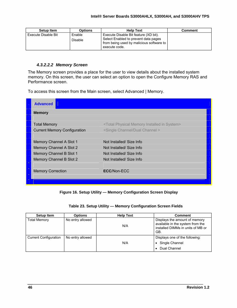
Intel® Server Boards S3000AHLX, S3000AH, and S3000AHV TPS
Revision 1.2
46
Setup Item Options Help Text Comment Execute Disable Bit Enable
Disable Execute Disable Bit feature (XD bit). Select Enabled to prevent data pages from being used by malicious software to execute code.
4.3.2.2.2 Memory Screen The Memory screen provides a place for the user to view details about the installed system memory. On this screen, the user can select an option to open the Configure Memory RAS and Performance screen.
To access this screen from the Main screen, select Advanced | Memory.
Advanced
Memory Total Memory <Total Physical Memory Installed in System> Current Memory Configuration <Single Channel/Dual Channel > Memory Channel A Slot 1 Not Installed/ Size Info Memory Channel A Slot 2 Not Installed/ Size Info Memory Channel B Slot 1 Not Installed/ Size Info Memory Channel B Slot 2 Not Installed/ Size Info Memory Correction ECC/Non-ECC
Figure 16. Setup Utility — Memory Configuration Screen Display
Table 23. Setup Utility — Memory Configuration Screen Fields
Setup Item Options Help Text Comment Total Memory No entry allowed
N/A
Displays the amount of memory available in the system from the installed DIMMs in units of MB or GB.
Current Configuration No entry allowed N/A
Displays one of the following: • Single Channel • Dual Channel
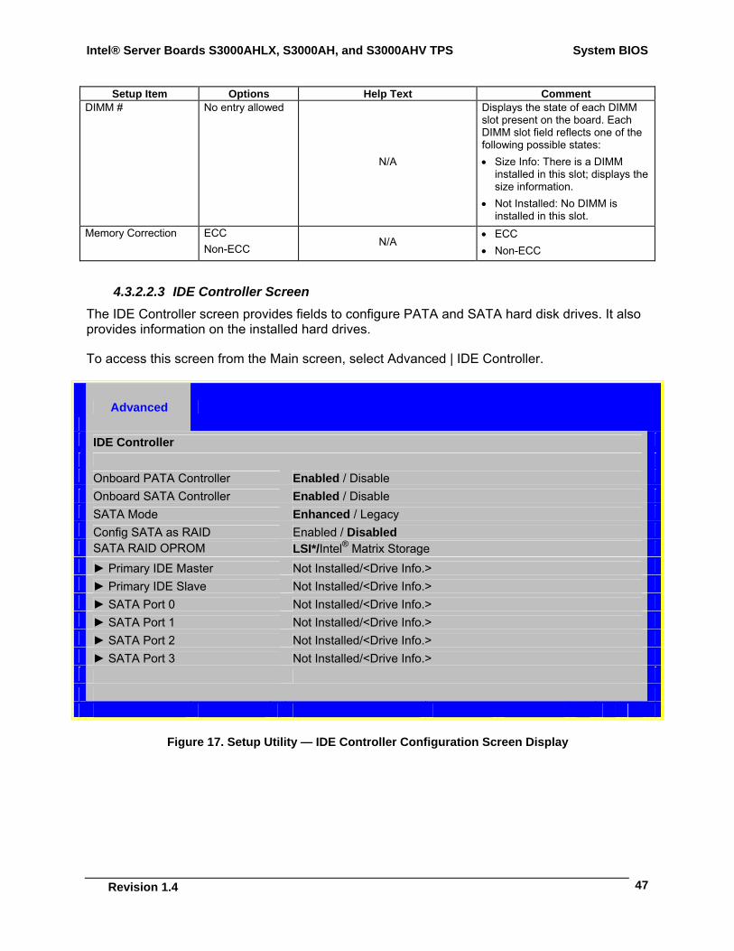
Intel® Server Boards S3000AHLX, S3000AH, and S3000AHV TPS System BIOS
Revision 1.4
47
Setup Item Options Help Text Comment DIMM # No entry allowed
N/A
Displays the state of each DIMM slot present on the board. Each DIMM slot field reflects one of the following possible states: • Size Info: There is a DIMM
installed in this slot; displays the size information.
• Not Installed: No DIMM is installed in this slot.
Memory Correction ECC Non-ECC
N/A • ECC • Non-ECC
4.3.2.2.3 IDE Controller Screen The IDE Controller screen provides fields to configure PATA and SATA hard disk drives. It also provides information on the installed hard drives.
To access this screen from the Main screen, select Advanced | IDE Controller.
Advanced
IDE Controller Onboard PATA Controller Enabled / Disable Onboard SATA Controller Enabled / Disable SATA Mode Enhanced / Legacy Config SATA as RAID Enabled / Disabled SATA RAID OPROM LSI*/Intel® Matrix Storage ► Primary IDE Master Not Installed/<Drive Info.> ► Primary IDE Slave Not Installed/<Drive Info.> ► SATA Port 0 Not Installed/<Drive Info.> ► SATA Port 1 Not Installed/<Drive Info.> ► SATA Port 2 Not Installed/<Drive Info.> ► SATA Port 3 Not Installed/<Drive Info.>
Figure 17. Setup Utility — IDE Controller Configuration Screen Display
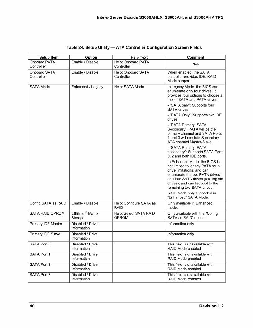
Intel® Server Boards S3000AHLX, S3000AH, and S3000AHV TPS
Revision 1.2
48
Table 24. Setup Utility — ATA Controller Configuration Screen Fields
Setup Item Option Help Text Comment Onboard PATA Controller
Enable / Disable Help: Onboard PATA Controller N/A
Onboard SATA Controller
Enable / Disable Help: Onboard SATA Controller
When enabled, the SATA controller provides IDE, RAID Mode support.
SATA Mode Enhanced / Legacy Help: SATA Mode In Legacy Mode, the BIOS can enumerate only four drives. It provides four options to choose a mix of SATA and PATA drives. - “SATA only”: Supports four SATA drives. - “PATA Only”: Supports two IDE drives. - “PATA Primary, SATA Secondary”: PATA will be the primary channel and SATA Ports 1 and 3 will emulate Secondary ATA channel Master/Slave. - “SATA Primary, PATA secondary”: Supports SATA Ports 0, 2 and both IDE ports. In Enhanced Mode, the BIOS is not limited to legacy PATA four-drive limitations, and can enumerate the two PATA drives and four SATA drives (totaling six drives), and can list/boot to the remaining two SATA drives. RAID Mode only supported in “Enhanced” SATA Mode.
Config SATA as RAID Enable / Disable Help: Configure SATA as RAID
Only available in Enhanced mode.
SATA RAID OPROM LSI/Intel® Matrix Storage
Help: Select SATA RAID OPROM
Only available with the “Config SATA as RAID” option
Primary IDE Master Disabled / Drive information
Information only
Primary IDE Slave Disabled / Drive information
Information only
SATA Port 0 Disabled / Drive information
This field is unavailable with RAID Mode enabled
SATA Port 1 Disabled / Drive information
This field is unavailable with RAID Mode enabled
SATA Port 2 Disabled / Drive information
This field is unavailable with RAID Mode enabled
SATA Port 3 Disabled / Drive information
This field is unavailable with RAID Mode enabled

Intel® Server Boards S3000AHLX, S3000AH, and S3000AHV TPS System BIOS
Revision 1.4
49
4.3.2.2.4 Serial Ports Screen The Serial Ports screen provides fields to configure the Serial A [COM 1] port.
To access this screen from the Main screen, select Advanced | Serial Port.
Advanced
Serial Port COM1 Enable Enable/Disable Address 3F8h / 2F8h IRQ 3 or 4
Figure 18. Setup Utility — Serial Port Configuration Screen Display
Table 25. Setup Utility — Serial Ports Configuration Screen Fields
Setup Item Option Help Text Comment COM1 Enable
Enabled Disabled
Enables or disables the COM1 port. N/A
Address 3F8h / 2F8h Selects the base I/O address for COM1. N/A IRQ 3 / 4 Selects the Interrupt Request line for COM1. N/A
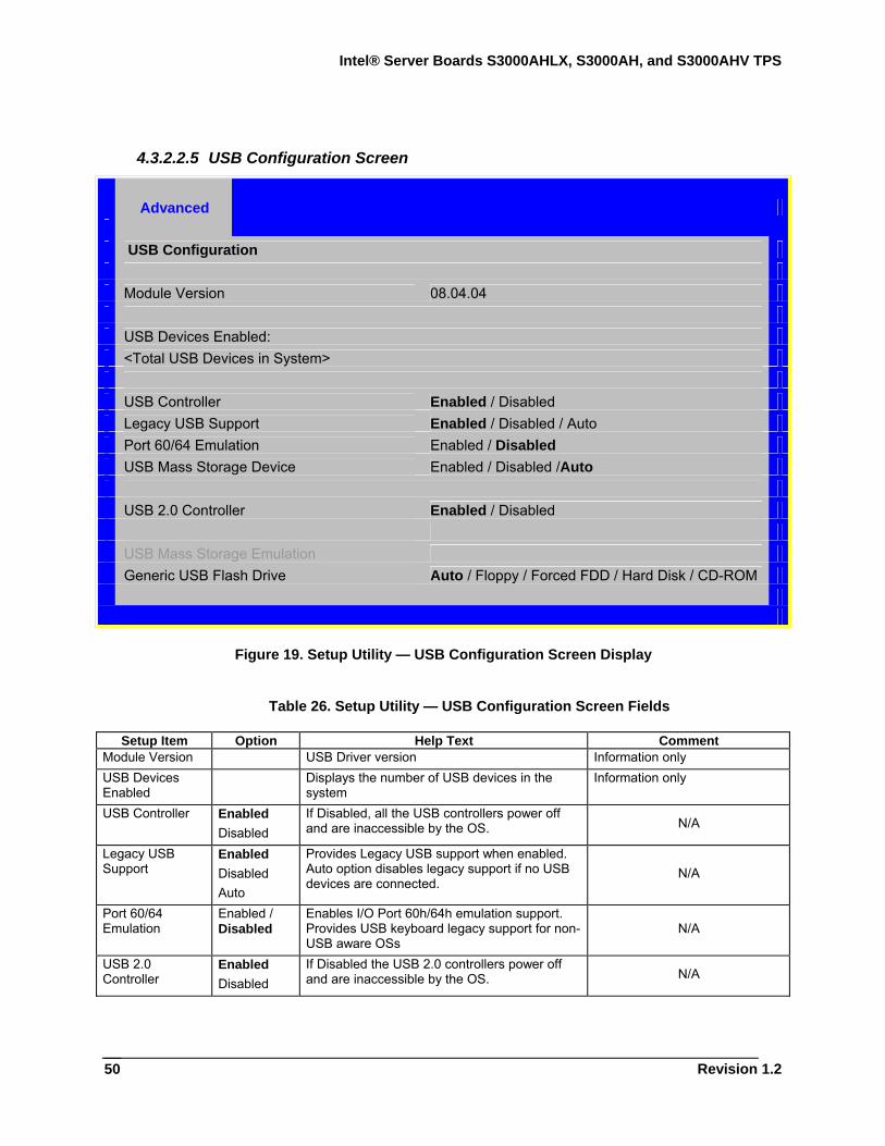
Intel® Server Boards S3000AHLX, S3000AH, and S3000AHV TPS
Revision 1.2
50
4.3.2.2.5 USB Configuration Screen
Advanced
USB Configuration Module Version 08.04.04 USB Devices Enabled: <Total USB Devices in System> USB Controller Enabled / Disabled Legacy USB Support Enabled / Disabled / Auto Port 60/64 Emulation Enabled / Disabled USB Mass Storage Device Enabled / Disabled /Auto USB 2.0 Controller Enabled / Disabled USB Mass Storage Emulation Generic USB Flash Drive Auto / Floppy / Forced FDD / Hard Disk / CD-ROM
Figure 19. Setup Utility — USB Configuration Screen Display
Table 26. Setup Utility — USB Configuration Screen Fields
Setup Item Option Help Text Comment Module Version USB Driver version Information only USB Devices Enabled
Displays the number of USB devices in the system
Information only
USB Controller Enabled Disabled
If Disabled, all the USB controllers power off and are inaccessible by the OS. N/A
Legacy USB Support
Enabled Disabled Auto
Provides Legacy USB support when enabled. Auto option disables legacy support if no USB devices are connected.
N/A
Port 60/64 Emulation
Enabled / Disabled
Enables I/O Port 60h/64h emulation support. Provides USB keyboard legacy support for non-USB aware OSs
N/A
USB 2.0 Controller
Enabled Disabled
If Disabled the USB 2.0 controllers power off and are inaccessible by the OS. N/A
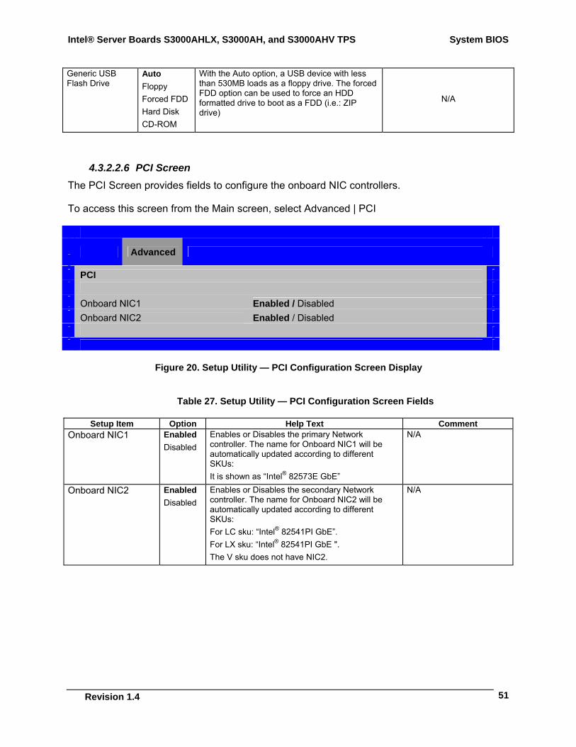
Intel® Server Boards S3000AHLX, S3000AH, and S3000AHV TPS System BIOS
Revision 1.4
51
Generic USB Flash Drive
Auto Floppy Forced FDD Hard Disk CD-ROM
With the Auto option, a USB device with less than 530MB loads as a floppy drive. The forced FDD option can be used to force an HDD formatted drive to boot as a FDD (i.e.: ZIP drive)
N/A
4.3.2.2.6 PCI Screen The PCI Screen provides fields to configure the onboard NIC controllers.
To access this screen from the Main screen, select Advanced | PCI
Advanced
PCI Onboard NIC1 Enabled / Disabled Onboard NIC2 Enabled / Disabled
Figure 20. Setup Utility — PCI Configuration Screen Display
Table 27. Setup Utility — PCI Configuration Screen Fields
Setup Item Option Help Text Comment Onboard NIC1 Enabled
Disabled Enables or Disables the primary Network controller. The name for Onboard NIC1 will be automatically updated according to different SKUs: It is shown as “Intel® 82573E GbE”
N/A
Onboard NIC2 Enabled Disabled
Enables or Disables the secondary Network controller. The name for Onboard NIC2 will be automatically updated according to different SKUs: For LC sku: “Intel® 82541PI GbE”. For LX sku: “Intel® 82541PI GbE ". The V sku does not have NIC2.
N/A
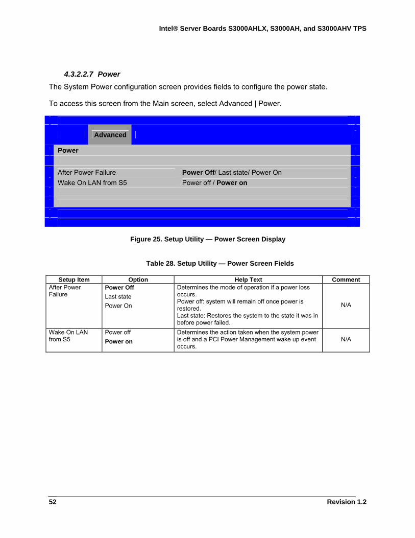
Intel® Server Boards S3000AHLX, S3000AH, and S3000AHV TPS
Revision 1.2
52
4.3.2.2.7 Power The System Power configuration screen provides fields to configure the power state.
To access this screen from the Main screen, select Advanced | Power.
Advanced
Power After Power Failure Power Off/ Last state/ Power On Wake On LAN from S5 Power off / Power on
Figure 25. Setup Utility — Power Screen Display
Table 28. Setup Utility — Power Screen Fields
Setup Item Option Help Text Comment After Power Failure
Power Off Last state Power On
Determines the mode of operation if a power loss occurs. Power off: system will remain off once power is restored. Last state: Restores the system to the state it was in before power failed.
N/A
Wake On LAN from S5
Power off Power on
Determines the action taken when the system power is off and a PCI Power Management wake up event occurs.
N/A
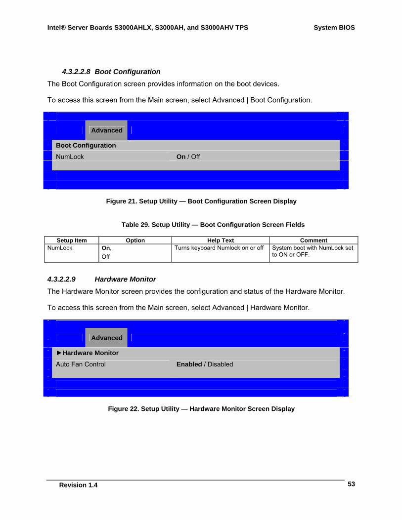
Intel® Server Boards S3000AHLX, S3000AH, and S3000AHV TPS System BIOS
Revision 1.4
53
4.3.2.2.8 Boot Configuration The Boot Configuration screen provides information on the boot devices.
To access this screen from the Main screen, select Advanced | Boot Configuration.
Advanced
Boot Configuration NumLock On / Off
Figure 21. Setup Utility — Boot Configuration Screen Display
Table 29. Setup Utility — Boot Configuration Screen Fields
Setup Item Option Help Text Comment NumLock On,
Off Turns keyboard Numlock on or off System boot with NumLock set
to ON or OFF.
4.3.2.2.9 Hardware Monitor The Hardware Monitor screen provides the configuration and status of the Hardware Monitor.
To access this screen from the Main screen, select Advanced | Hardware Monitor.
Advanced
►Hardware Monitor Auto Fan Control Enabled / Disabled
Figure 22. Setup Utility — Hardware Monitor Screen Display
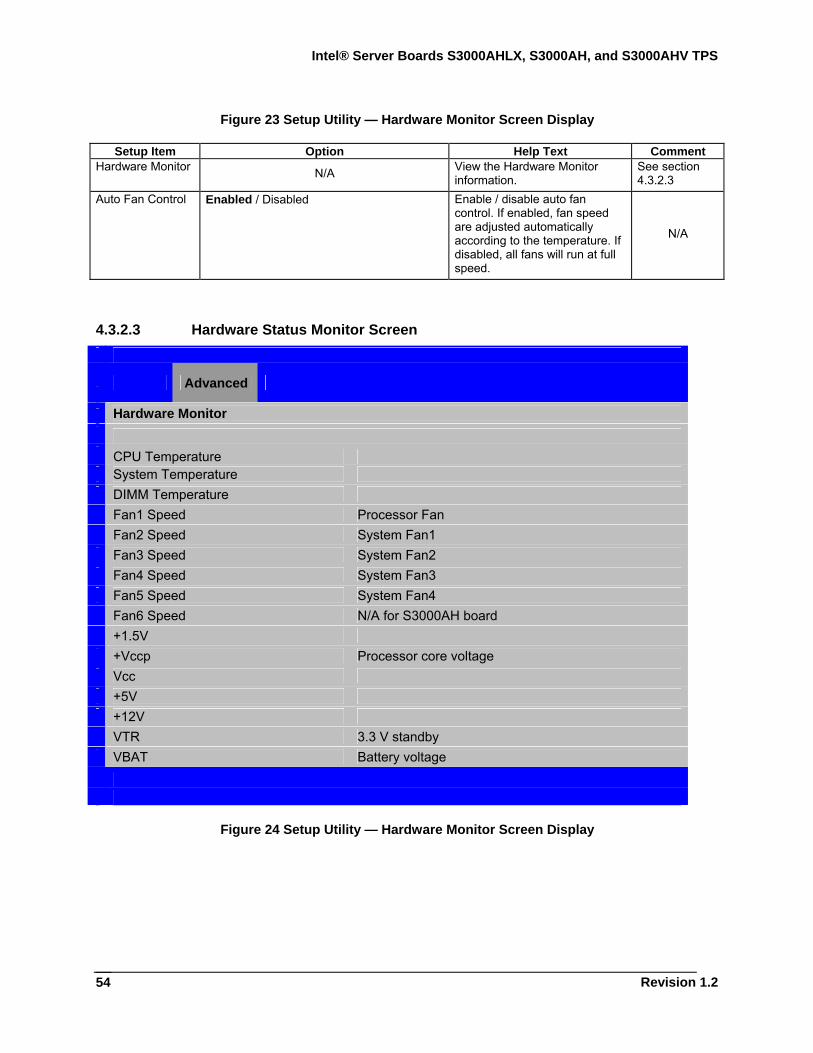
Intel® Server Boards S3000AHLX, S3000AH, and S3000AHV TPS
Revision 1.2
54
Figure 23 Setup Utility — Hardware Monitor Screen Display
Setup Item Option Help Text Comment Hardware Monitor N/A View the Hardware Monitor
information. See section 4.3.2.3
Auto Fan Control Enabled / Disabled Enable / disable auto fan control. If enabled, fan speed are adjusted automatically according to the temperature. If disabled, all fans will run at full speed.
N/A
4.3.2.3 Hardware Status Monitor Screen
Advanced
Hardware Monitor CPU Temperature System Temperature DIMM Temperature Fan1 Speed Processor Fan Fan2 Speed System Fan1 Fan3 Speed System Fan2 Fan4 Speed System Fan3 Fan5 Speed System Fan4 Fan6 Speed N/A for S3000AH board +1.5V +Vccp Processor core voltage Vcc +5V +12V VTR 3.3 V standby VBAT Battery voltage
Figure 24 Setup Utility — Hardware Monitor Screen Display
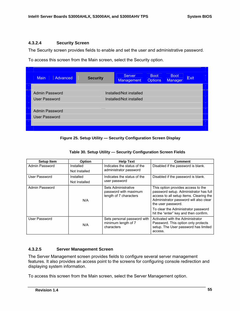
Intel® Server Boards S3000AHLX, S3000AH, and S3000AHV TPS System BIOS
Revision 1.4
55
4.3.2.4 Security Screen The Security screen provides fields to enable and set the user and administrative password.
To access this screen from the Main screen, select the Security option.
Main Advanced Security Server
Management Boot
Options Boot
Manager Exit
Admin Password Installed/Not installed User Password Installed/Not installed Admin Password User Password
Figure 25. Setup Utility — Security Configuration Screen Display
Table 30. Setup Utility — Security Configuration Screen Fields
Setup Item Option Help Text Comment Admin Password Installed
Not Installed Indicates the status of the administrator password
Disabled if the password is blank.
User Password Installed Not Installed
Indicates the status of the user password
Disabled if the password is blank.
Admin Password
N/A
Sets Administrative password with maximum length of 7 characters
This option provides access to the password setup. Administrator has full access to all setup items. Clearing the Administrator password will also clear the user password. To clear the Administrator password hit the “enter” key and then confirm.
User Password
N/A
Sets personal password with minimum length of 7 characters
Activated with the Administrator Password. This option only protects setup. The User password has limited access.
4.3.2.5 Server Management Screen The Server Management screen provides fields to configure several server management features. It also provides an access point to the screens for configuring console redirection and displaying system information.
To access this screen from the Main screen, select the Server Management option.
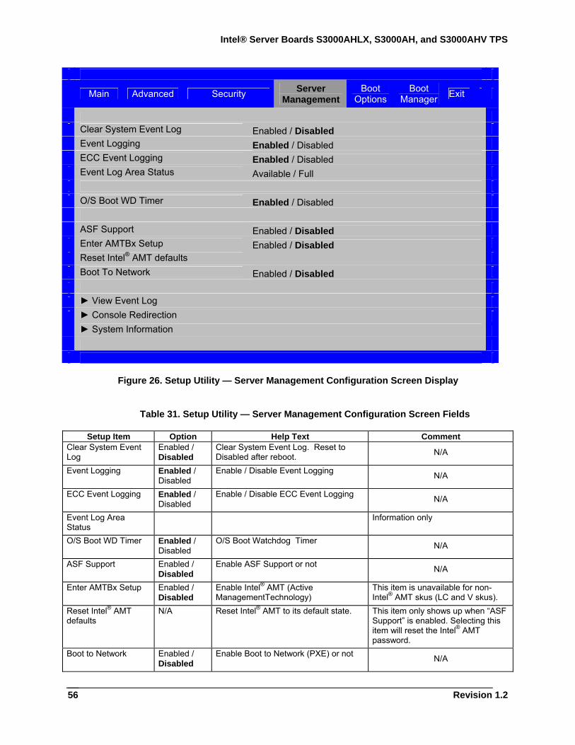
Intel® Server Boards S3000AHLX, S3000AH, and S3000AHV TPS
Revision 1.2
56
Main Advanced Security Server
Management Boot
Options Boot
Manager Exit
Clear System Event Log Enabled / Disabled Event Logging Enabled / Disabled ECC Event Logging Enabled / Disabled Event Log Area Status Available / Full O/S Boot WD Timer Enabled / Disabled ASF Support Enabled / Disabled Enter AMTBx Setup Enabled / Disabled Reset Intel® AMT defaults Boot To Network Enabled / Disabled
► View Event Log ► Console Redirection ► System Information
Figure 26. Setup Utility — Server Management Configuration Screen Display
Table 31. Setup Utility — Server Management Configuration Screen Fields
Setup Item Option Help Text Comment Clear System Event Log
Enabled / Disabled
Clear System Event Log. Reset to Disabled after reboot. N/A
Event Logging Enabled / Disabled
Enable / Disable Event Logging N/A
ECC Event Logging Enabled / Disabled
Enable / Disable ECC Event Logging N/A
Event Log Area Status
Information only
O/S Boot WD Timer Enabled / Disabled
O/S Boot Watchdog Timer N/A
ASF Support Enabled / Disabled
Enable ASF Support or not N/A
Enter AMTBx Setup Enabled / Disabled
Enable Intel® AMT (Active ManagementTechnology)
This item is unavailable for non-Intel® AMT skus (LC and V skus).
Reset Intel® AMT defaults
N/A Reset Intel® AMT to its default state. This item only shows up when “ASF Support” is enabled. Selecting this item will reset the Intel® AMT password.
Boot to Network Enabled / Disabled
Enable Boot to Network (PXE) or not N/A
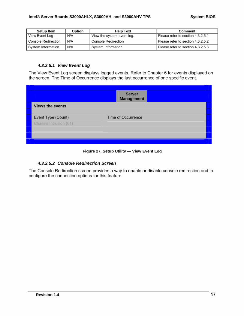
Intel® Server Boards S3000AHLX, S3000AH, and S3000AHV TPS System BIOS
Revision 1.4
57
Setup Item Option Help Text Comment View Event Log N/A View the system event log. Please refer to section 4.3.2.5.1 Console Redirection N/A Console Redirection Please refer to section 4.3.2.5.2 System Information N/A System Information Please refer to section 4.3.2.5.3
4.3.2.5.1 View Event Log The View Event Log screen displays logged events. Refer to Chapter 6 for events displayed on the screen. The Time of Occurrence displays the last occurrence of one specific event.
Server
Management
Views the events Event Type (Count) Time of Occurrence Chassis Intrusion (01)
Figure 27. Setup Utility — View Event Log
4.3.2.5.2 Console Redirection Screen The Console Redirection screen provides a way to enable or disable console redirection and to configure the connection options for this feature.
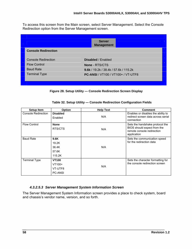
Intel® Server Boards S3000AHLX, S3000AH, and S3000AHV TPS
Revision 1.2
58
To access this screen from the Main screen, select Server Management. Select the Console Redirection option from the Server Management screen.
Server
Management
Console Redirection Console Redirection Disabled / Enabled Flow Control None - RTS/CTS Baud Rate 9.6k / 19.2k / 38.4k / 57.6k / 115.2k Terminal Type PC-ANSI / VT100 / VT100+ / VT-UTF8
Figure 28. Setup Utility — Console Redirection Screen Display
Table 32. Setup Utility — Console Redirection Configuration Fields
Setup Item Option Help Text Comment Console Redirection Disabled
Enabled N/A Enables or disables the ability to redirect screen data across serial connection
Flow Control None RTS/CTS N/A
Sets the handshake protocol the BIOS should expect from the remote console redirection application
Baud Rate 9.6K 19.2K 36.4K 57.6K 115.2K
N/A
Sets the communication speed for the redirection data
Terminal Type VT100 VT100+ VT-UTF8 PC-ANSI
N/A
Sets the character formatting for the console redirection screen
4.3.2.5.3 Server Management System Information Screen The Server Management System Information screen provides a place to check system, board and chassis’s vendor name, version, and so forth.
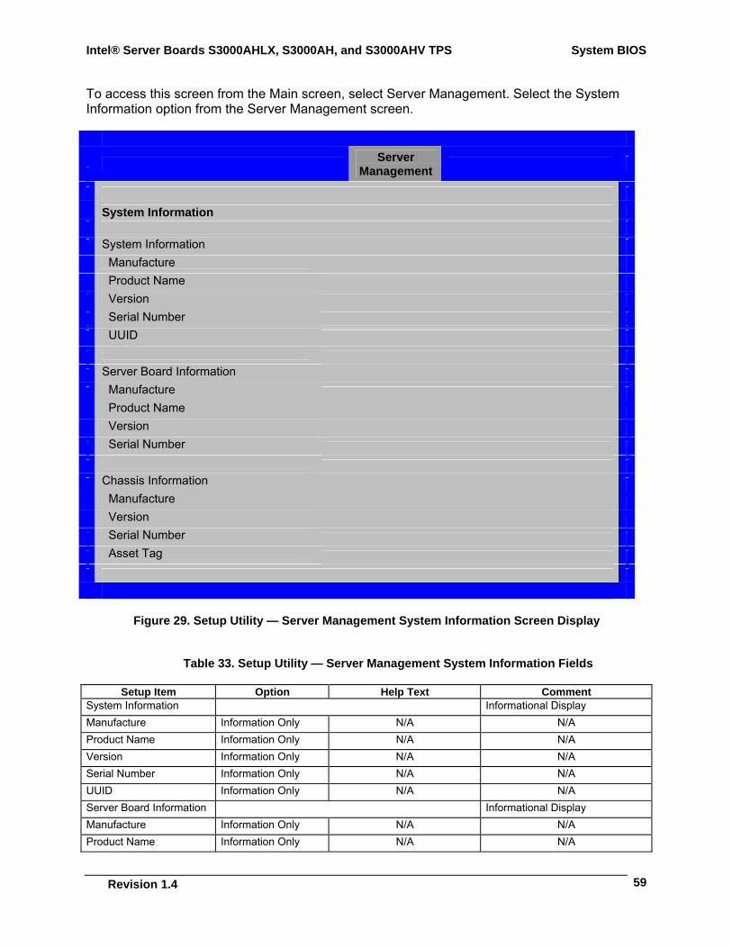
Intel® Server Boards S3000AHLX, S3000AH, and S3000AHV TPS System BIOS
Revision 1.4
59
To access this screen from the Main screen, select Server Management. Select the System Information option from the Server Management screen.
Server
Management
System Information System Information Manufacture Product Name Version Serial Number UUID
Server Board Information Manufacture Product Name Version Serial Number Chassis Information Manufacture Version Serial Number Asset Tag
Figure 29. Setup Utility — Server Management System Information Screen Display
Table 33. Setup Utility — Server Management System Information Fields
Setup Item Option Help Text Comment System Information Informational Display Manufacture Information Only N/A N/A Product Name Information Only N/A N/A Version Information Only N/A N/A Serial Number Information Only N/A N/A UUID Information Only N/A N/A Server Board Information Informational Display Manufacture Information Only N/A N/A Product Name Information Only N/A N/A
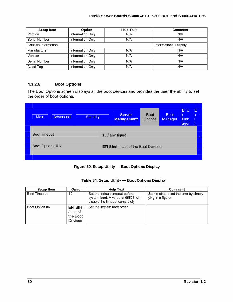
Intel® Server Boards S3000AHLX, S3000AH, and S3000AHV TPS
Revision 1.2
60
Setup Item Option Help Text Comment Version Information Only N/A N/A Serial Number Information Only N/A N/A Chassis Information Informational Display Manufacture Information Only N/A N/A Version Information Only N/A N/A Serial Number Information Only N/A N/A Asset Tag Information Only N/A N/A
4.3.2.6 Boot Options The Boot Options screen displays all the boot devices and provides the user the ability to set the order of boot options.
Main Advanced Security Server Management
Boot Options
Boot Manager
Error Manager
Exit
Boot timeout 10 / any figure Boot Options # N EFI Shell / List of the Boot Devices
Figure 30. Setup Utility — Boot Options Display
Table 34. Setup Utility — Boot Options Display
Setup Item Option Help Text Comment Boot Timeout 10 Set the default timeout before
system boot. A value of 65535 will disable the timeout completely.
User is able to set the time by simply tying in a figure.
Boot Option #N EFI Shell / List of the Boot Devices
Set the system boot order
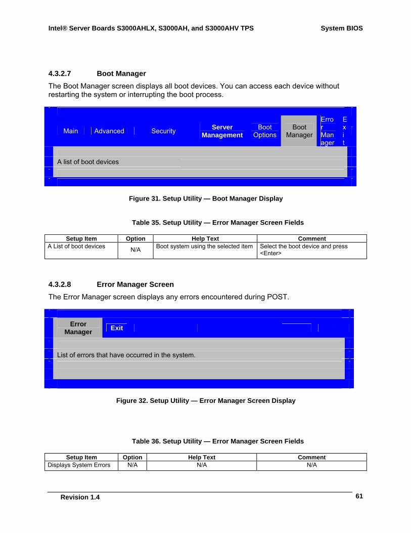
Intel® Server Boards S3000AHLX, S3000AH, and S3000AHV TPS System BIOS
Revision 1.4
61
4.3.2.7 Boot Manager The Boot Manager screen displays all boot devices. You can access each device without restarting the system or interrupting the boot process.
Main Advanced Security Server Management
Boot Options
Boot Manager
Error Manager
Exit
A list of boot devices
Figure 31. Setup Utility — Boot Manager Display
Table 35. Setup Utility — Error Manager Screen Fields
Setup Item Option Help Text Comment A List of boot devices N/A Boot system using the selected item Select the boot device and press
<Enter>
4.3.2.8 Error Manager Screen The Error Manager screen displays any errors encountered during POST.
Error
Manager Exit
List of errors that have occurred in the system.
Figure 32. Setup Utility — Error Manager Screen Display
Table 36. Setup Utility — Error Manager Screen Fields
Setup Item Option Help Text Comment Displays System Errors N/A N/A N/A
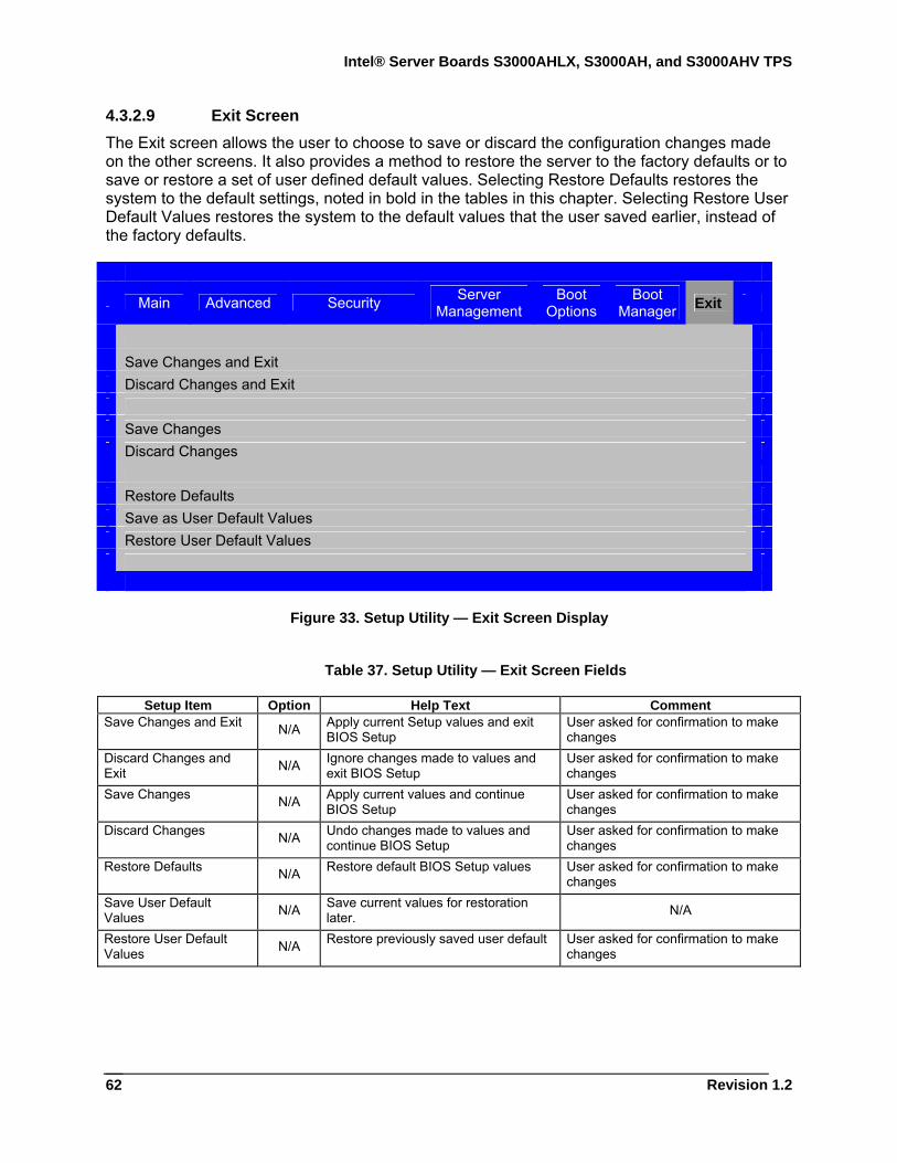
Intel® Server Boards S3000AHLX, S3000AH, and S3000AHV TPS
Revision 1.2
62
4.3.2.9 Exit Screen The Exit screen allows the user to choose to save or discard the configuration changes made on the other screens. It also provides a method to restore the server to the factory defaults or to save or restore a set of user defined default values. Selecting Restore Defaults restores the system to the default settings, noted in bold in the tables in this chapter. Selecting Restore User Default Values restores the system to the default values that the user saved earlier, instead of the factory defaults.
Main Advanced Security Server
Management Boot
Options Boot
Manager Exit
Save Changes and Exit Discard Changes and Exit Save Changes Discard Changes Restore Defaults Save as User Default Values Restore User Default Values
Figure 33. Setup Utility — Exit Screen Display
Table 37. Setup Utility — Exit Screen Fields
Setup Item Option Help Text Comment Save Changes and Exit N/A Apply current Setup values and exit
BIOS Setup User asked for confirmation to make changes
Discard Changes and Exit N/A Ignore changes made to values and
exit BIOS Setup User asked for confirmation to make changes
Save Changes N/A Apply current values and continue BIOS Setup
User asked for confirmation to make changes
Discard Changes N/A Undo changes made to values and continue BIOS Setup
User asked for confirmation to make changes
Restore Defaults N/A Restore default BIOS Setup values User asked for confirmation to make changes
Save User Default Values N/A Save current values for restoration
later. N/A
Restore User Default Values N/A Restore previously saved user default User asked for confirmation to make
changes
Intel® Server Boards S3000AHLX, S3000AH, and S3000AHV TPS System BIOS
Revision 1.4
63
4.4 Loading BIOS Defaults Different mechanisms exist for resetting the system configuration to the default values. When a request to reset the system configuration is detected, the BIOS loads the default system configuration values during the next POST. To reset the system to the defaults:
Use the BIOS System Configuration Utility (Setup) to reset the system configuration. Generate a reset system configuration request by moving the clear system configuration
jumper.
4.5 Multiple Boot Blocks Two boot blocks are available on this server board. Multiple Boot Blocks fault tolerant realization requires BIOS to:
Recognize the second boot block and dispatch modules within it. Provide a flash update interface (for the utility) that has a fault-tolerant flash update
algorithm embedded that provides a set of boot blocks to recover the system settings if the flash update fails.
4.6 Recovery Mode You can initiate a recovery process by setting the recovery jumper (called Force Recovery), which can be invoked because of flash damage.
To complete a BIOS recover, use an ATAPI-CD. Use the El-Torito format image to create an ATAPI-CD image for recovery. For more information, refer to Bios release notes.
The recovery media must contain the image file FV_MAIN.FV. The system should also contain a DOS bootable disk (HD, USB drives, CD-ROM, and so forth) which must include the following image files:
IFLASH32.EXE *.CAP AUTOEXEC.BAT
The BIOS starts the recovery process by first loading and booting to the recovery image file (FV_MAIN.FV) on the root directory of the inserted ATAPI-CD. This process takes place before any video or console is available. Once the system boots to this recovery image file (FV_MAIN.FV), the user must select the option to boot from the DOS disk, which contains the files in the list above. The process continues by loading and executing the AUTOEXEC.BAT file and the flash update application (IFLASH32.EXE). IFLASH32.EXE requires the supporting BIOS Capsule image file (*.CAP).
Once the recovery process is complete, the user must switch the recovery jumper back to normal operation and restart the system with a power cycle.
Intel® Server Boards S3000AHLX, S3000AH, and S3000AHV TPS
Revision 1.2
64
Perform the following steps to complete the recovery process:
1. Insert recovery media with the FV_MAIN.FV in the root directory.
2. Insert the disk with the required files (IFLASH32.EXE, AUTOEXEC.BAT, *.CAP). Note: To save time, combine the files for Steps 1 and 2 onto one disk.
3. Change the recovery mode jumper (BIOS RECV) from normal operation to recovery operation. The details of the jumper are available in the server board EPS.
4. Power on the system.
5. The BIOS POST screen appears and displays the progress. The BIOS continues to boot to DOS from the media.
6. The AUTOEXEC.BAT file loads and initiates the flash update (IFLASH32.EXE) with new capsule file (*.CAP). If the flash update succeeds or fails, a message displays.
7. Once the flash update is completed, put the recovery jumper back to the default position for normal operation.
8. Perform the power cycle.
4.7 Intel® Matrix Storage Manager Intel® Matrix Storage Manager provides software support for high-performance SATA RAID 0 arrays, fault-tolerant SATA RAID 1 arrays, high-capacity and fault-tolerant SATA RAID 5 arrays, and high performance and fault-tolerant SATA RAID 10 arrays on select supported chipsets using select operating systems. Intel® Matrix Storage Manager is the software that enables Intel® Matrix Storage Technology.
For detailed information and supported operating systems, refer to the following Web site: http://support.intel.com/support/chipsets/imsm/
4.8 Intel® Embedded Server RAID Technology Intel® Embedded Server RAID Technology supports four SATA ports, which provides a cost-effective way to achieve higher transfer rates and reliability. Intel® Embedded Server RAID Technology supports
RAID level 0 data striping for improved performance RAID level 1 data mirroring for improved data reliability RAID level 10 data striping and mirroring for high data transfer rates and data
redundancy
Note: You cannot use normal SATA devices when the RAID option is enabled.

Intel® Server Boards S3000AHLX, S3000AH, and S3000AHV TPS
Revision 1.4
65
5. Error Reporting and Handling This chapter defines the following error handling features:
Error Handling and Logging Error Messages and Beep Codes
5.1 Error Handling and Logging This section defines how errors are handled by the system BIOS. It also includes a description of error-logging techniques and error beep codes.
5.1.1 Error Sources and Types One of the major requirements of server management is to handle system errors correctly and consistently. You can enable and disable system errors individually or as a group. The errors fall into one of the following categories:
PCI bus errors Memory single- and multi-bit errors Errors detected during POST, logged as POST errors
The following table shows an error event list.
Table 38. Event List
Event Name Description When Error Is Caught Processor thermal trip of last boot Processor thermal trip happened on
last boot POST
Memory channel A Multi-bit ECC error
DIMM channel A Multi-bit ECC error POST / Runtime
Memory channel A Single-bit ECC error
DIMM channel A Single-bit ECC error
POST / Runtime
Memory channel B Multi-bit ECC error
DIMM channel B Multi-bit ECC error POST / Runtime
Memory channel B Single-bit ECC error
Single-bit ECC error happened on DIMM channel B
POST / Runtime
CMOS battery failure CMOS battery failure or CMOS clear jumper is set to clear CMOS
POST
CMOS checksum error CMOS data crushed POST CMOS time not set CMOS time is not set POST Keyboard not found PS/2 KB is not found during POST POST Memory size decrease Memory size is decreased
compared with last boot POST
Chassis intrusion detected Chassis is open POST Bad SPD tolerance Some fields of the DIMM SPD may
not be supported, but could be tolerant by the Memory Reference
POST
Intel® Server Boards S3000AHLX, S3000AH, and S3000AHV TPS Error Reporting and Handling
Revision 1.2
66
Event Name Description When Error Is Caught Code
PCI PERR error PERR error happens on PCI bus POST / Runtime PCI SERR error SERR error happens on PCI bus POST / Runtime
5.1.2 Error Logging via SMI Handler The SMI handler handles and logs system level events. The SMI handler pre-processes all system errors, even those that normally generate an NMI.
The SMI handler logs the event to NVRAM. For example, the BIOS programs the hardware to generate SMI on a single-bit memory error and logs the error in the NVRAM in the terms of SMBIOS Type 15. After the BIOS finishes logging the error, it asserts the NMI if needed.
5.1.2.1 PCI Bus Error The PCI bus defines two error pins, PERR# and SERR#. They report PCI parity errors and system errors, respectively.
In the case of PERR#, the PCI bus master has the option to retry the offending transaction or to report it using SERR#. SERR# reports all other PCI-related errors. All PCI-to-PCI bridges generate SERR# on the primary interface whenever there is SERR# on the secondary side. For more information on the format of the data bytes, refer to Section 5.1.4.
5.1.2.2 PCI Express* Errors All uncorrectable PCI Express* errors are logged as PCI system errors and promoted to an NMI. All correctable PCI Express errors are logged as PCI parity errors.
5.1.2.3 Memory Errors The hardware is programmed to generate an SMI on correctable data errors in the memory array. The SMI handler records the error to the NVRAM. The uncorrectable errors may have corrupted the contents of SMRAM. If the SMRAM contents are still valid, the SMI handler logs the error to the NVRAM. For more information on the format of the data bytes, refer to Section 5.1.4.
5.1.3 SMBIOS Type 15 Errors are logged to NVRAM in the terms of SMBIOS Type 15 (System Event Log). Refer to the SMBIOS Specification, version 2.4 for more information. The following section reviews the format of the records.
5.1.4 Logging Format Conventions The BIOS logs an error into the NVRAM area with record format described in the following table. For more information, refer to the SMBIOS Specification, version 2.4.
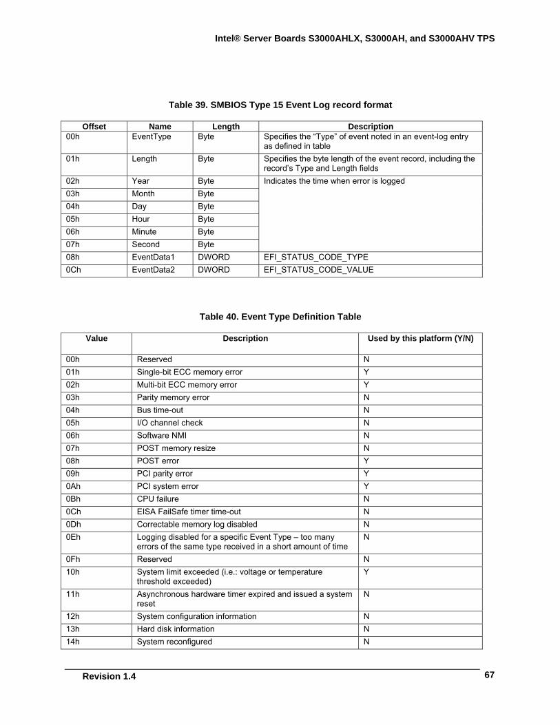
Intel® Server Boards S3000AHLX, S3000AH, and S3000AHV TPS
Revision 1.4
67
Table 39. SMBIOS Type 15 Event Log record format
Offset Name Length Description 00h EventType Byte Specifies the “Type” of event noted in an event-log entry
as defined in table 01h Length Byte Specifies the byte length of the event record, including the
record’s Type and Length fields 02h Year Byte 03h Month Byte 04h Day Byte 05h Hour Byte 06h Minute Byte 07h Second Byte
Indicates the time when error is logged
08h EventData1 DWORD EFI_STATUS_CODE_TYPE 0Ch EventData2 DWORD EFI_STATUS_CODE_VALUE
Table 40. Event Type Definition Table
Value Description Used by this platform (Y/N)
00h Reserved N 01h Single-bit ECC memory error Y 02h Multi-bit ECC memory error Y 03h Parity memory error N 04h Bus time-out N 05h I/O channel check N 06h Software NMI N 07h POST memory resize N 08h POST error Y 09h PCI parity error Y 0Ah PCI system error Y 0Bh CPU failure N 0Ch EISA FailSafe timer time-out N 0Dh Correctable memory log disabled N 0Eh Logging disabled for a specific Event Type – too many
errors of the same type received in a short amount of time N
0Fh Reserved N 10h System limit exceeded (i.e.: voltage or temperature
threshold exceeded) Y
11h Asynchronous hardware timer expired and issued a system reset
N
12h System configuration information N 13h Hard disk information N 14h System reconfigured N
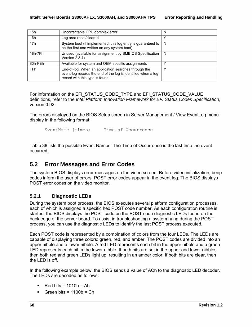
Intel® Server Boards S3000AHLX, S3000AH, and S3000AHV TPS Error Reporting and Handling
Revision 1.2
68
15h Uncorrectable CPU-complex error N 16h Log area reset/cleared Y 17h System boot (if implemented, this log entry is guaranteed to
be the first one written on any system boot) N
18h-7Fh Unused (available for assignment by SMBIOS Specification Version 2.3.4)
N
80h-FEh Available for system and OEM-specific assignments Y FFh End-of-log. When an application searches through the
event-log records the end of the log is identified when a log record with this type is found.
Y
For information on the EFI_STATUS_CODE_TYPE and EFI_STATUS_CODE_VALUE definitions, refer to the Intel Platform Innovation Framework for EFI Status Codes Specification, version 0.92.
The errors displayed on the BIOS Setup screen in Server Management / View EventLog menu display in the following format:
EventName (times) Time of Occurrence
Table 38 lists the possible Event Names. The Time of Occurrence is the last time the event occurred.
5.2 Error Messages and Error Codes The system BIOS displays error messages on the video screen. Before video initialization, beep codes inform the user of errors. POST error codes appear in the event log. The BIOS displays POST error codes on the video monitor.
5.2.1 Diagnostic LEDs During the system boot process, the BIOS executes several platform configuration processes, each of which is assigned a specific hex POST code number. As each configuration routine is started, the BIOS displays the POST code on the POST code diagnostic LEDs found on the back edge of the server board. To assist in troubleshooting a system hang during the POST process, you can use the diagnostic LEDs to identify the last POST process executed.
Each POST code is represented by a combination of colors from the four LEDs. The LEDs are capable of displaying three colors: green, red, and amber. The POST codes are divided into an upper nibble and a lower nibble. A red LED represents each bit in the upper nibble and a green LED represents each bit in the lower nibble. If both bits are set in the upper and lower nibbles then both red and green LEDs light up, resulting in an amber color. If both bits are clear, then the LED is off.
In the following example below, the BIOS sends a value of ACh to the diagnostic LED decoder. The LEDs are decoded as follows:
Red bits = 1010b = Ah Green bits = 1100b = Ch
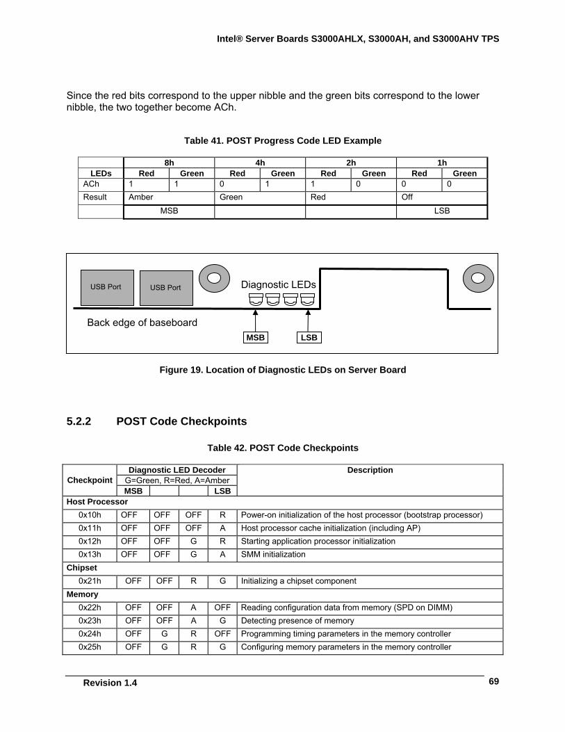
Intel® Server Boards S3000AHLX, S3000AH, and S3000AHV TPS
Revision 1.4
69
Since the red bits correspond to the upper nibble and the green bits correspond to the lower nibble, the two together become ACh.
Table 41. POST Progress Code LED Example
8h 4h 2h 1h LEDs Red Green Red Green Red Green Red Green
ACh 1 1 0 1 1 0 0 0 Result Amber Green Red Off
MSB LSB
Figure 19. Location of Diagnostic LEDs on Server Board
5.2.2 POST Code Checkpoints
Table 42. POST Code Checkpoints
Diagnostic LED Decoder G=Green, R=Red, A=Amber Checkpoint MSB LSB
Description
Host Processor 0x10h OFF OFF OFF R Power-on initialization of the host processor (bootstrap processor) 0x11h OFF OFF OFF A Host processor cache initialization (including AP) 0x12h OFF OFF G R Starting application processor initialization 0x13h OFF OFF G A SMM initialization
Chipset 0x21h OFF OFF R G Initializing a chipset component
Memory 0x22h OFF OFF A OFF Reading configuration data from memory (SPD on DIMM) 0x23h OFF OFF A G Detecting presence of memory 0x24h OFF G R OFF Programming timing parameters in the memory controller 0x25h OFF G R G Configuring memory parameters in the memory controller
LSBMSB
Diagnostic LEDs
Back edge of baseboard
USB Port USB Port
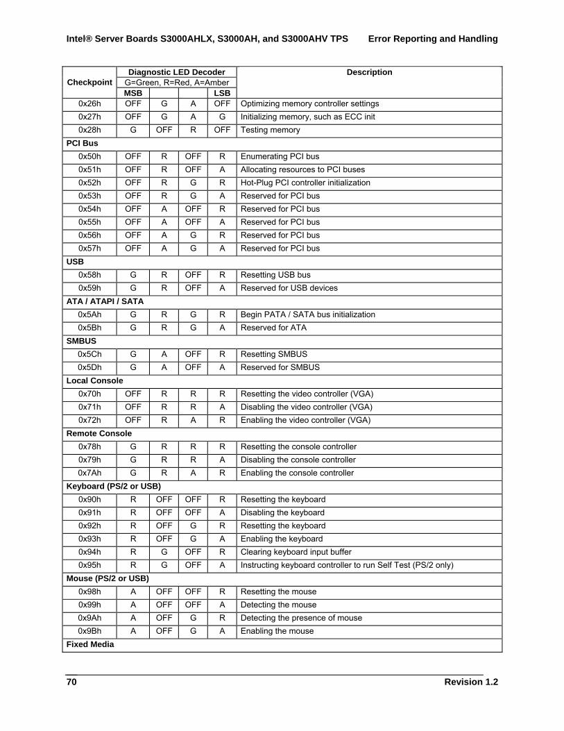
Intel® Server Boards S3000AHLX, S3000AH, and S3000AHV TPS Error Reporting and Handling
Revision 1.2
70
Diagnostic LED Decoder G=Green, R=Red, A=Amber Checkpoint MSB LSB
Description
0x26h OFF G A OFF Optimizing memory controller settings 0x27h OFF G A G Initializing memory, such as ECC init 0x28h G OFF R OFF Testing memory
PCI Bus 0x50h OFF R OFF R Enumerating PCI bus 0x51h OFF R OFF A Allocating resources to PCI buses 0x52h OFF R G R Hot-Plug PCI controller initialization 0x53h OFF R G A Reserved for PCI bus 0x54h OFF A OFF R Reserved for PCI bus 0x55h OFF A OFF A Reserved for PCI bus 0x56h OFF A G R Reserved for PCI bus 0x57h OFF A G A Reserved for PCI bus
USB 0x58h G R OFF R Resetting USB bus 0x59h G R OFF A Reserved for USB devices
ATA / ATAPI / SATA 0x5Ah G R G R Begin PATA / SATA bus initialization 0x5Bh G R G A Reserved for ATA
SMBUS 0x5Ch G A OFF R Resetting SMBUS 0x5Dh G A OFF A Reserved for SMBUS
Local Console 0x70h OFF R R R Resetting the video controller (VGA) 0x71h OFF R R A Disabling the video controller (VGA) 0x72h OFF R A R Enabling the video controller (VGA)
Remote Console 0x78h G R R R Resetting the console controller 0x79h G R R A Disabling the console controller 0x7Ah G R A R Enabling the console controller
Keyboard (PS/2 or USB) 0x90h R OFF OFF R Resetting the keyboard 0x91h R OFF OFF A Disabling the keyboard 0x92h R OFF G R Resetting the keyboard 0x93h R OFF G A Enabling the keyboard 0x94h R G OFF R Clearing keyboard input buffer 0x95h R G OFF A Instructing keyboard controller to run Self Test (PS/2 only)
Mouse (PS/2 or USB) 0x98h A OFF OFF R Resetting the mouse 0x99h A OFF OFF A Detecting the mouse 0x9Ah A OFF G R Detecting the presence of mouse 0x9Bh A OFF G A Enabling the mouse
Fixed Media
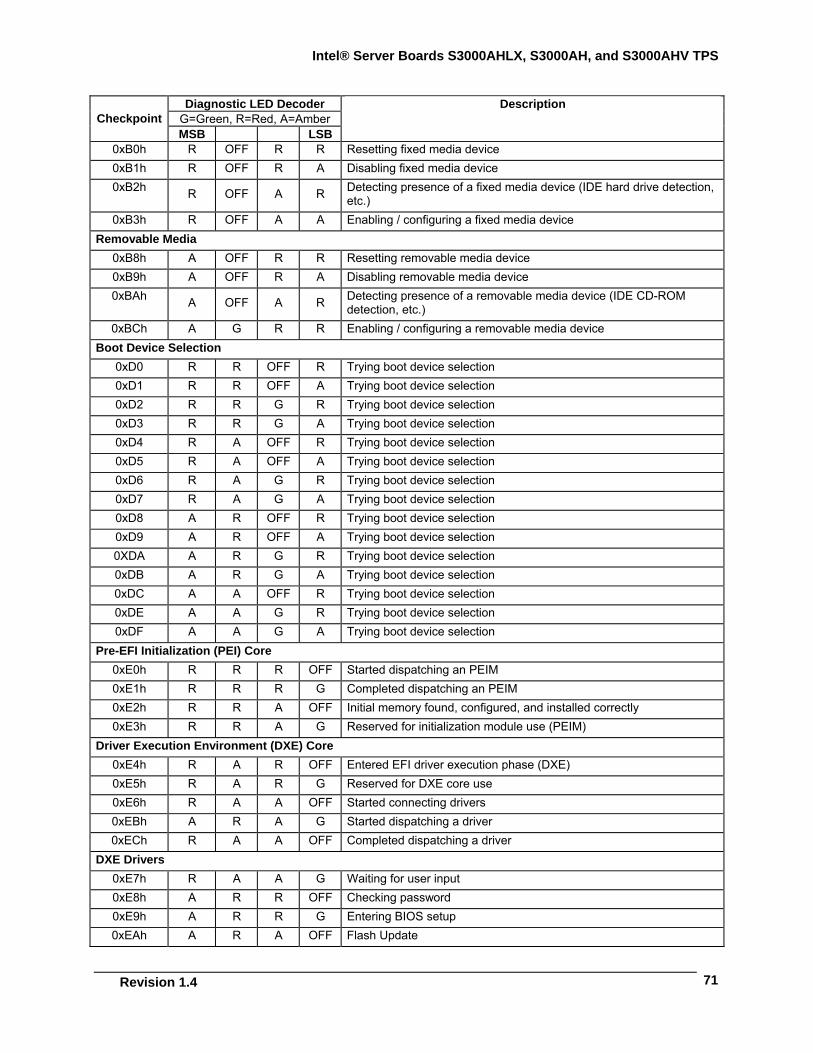
Intel® Server Boards S3000AHLX, S3000AH, and S3000AHV TPS
Revision 1.4
71
Diagnostic LED Decoder G=Green, R=Red, A=Amber Checkpoint MSB LSB
Description
0xB0h R OFF R R Resetting fixed media device 0xB1h R OFF R A Disabling fixed media device 0xB2h R OFF A R Detecting presence of a fixed media device (IDE hard drive detection,
etc.) 0xB3h R OFF A A Enabling / configuring a fixed media device
Removable Media 0xB8h A OFF R R Resetting removable media device 0xB9h A OFF R A Disabling removable media device 0xBAh A OFF A R Detecting presence of a removable media device (IDE CD-ROM
detection, etc.) 0xBCh A G R R Enabling / configuring a removable media device
Boot Device Selection 0xD0 R R OFF R Trying boot device selection 0xD1 R R OFF A Trying boot device selection 0xD2 R R G R Trying boot device selection 0xD3 R R G A Trying boot device selection 0xD4 R A OFF R Trying boot device selection 0xD5 R A OFF A Trying boot device selection 0xD6 R A G R Trying boot device selection 0xD7 R A G A Trying boot device selection 0xD8 A R OFF R Trying boot device selection 0xD9 A R OFF A Trying boot device selection 0XDA A R G R Trying boot device selection 0xDB A R G A Trying boot device selection 0xDC A A OFF R Trying boot device selection 0xDE A A G R Trying boot device selection 0xDF A A G A Trying boot device selection
Pre-EFI Initialization (PEI) Core 0xE0h R R R OFF Started dispatching an PEIM 0xE1h R R R G Completed dispatching an PEIM 0xE2h R R A OFF Initial memory found, configured, and installed correctly 0xE3h R R A G Reserved for initialization module use (PEIM)
Driver Execution Environment (DXE) Core 0xE4h R A R OFF Entered EFI driver execution phase (DXE) 0xE5h R A R G Reserved for DXE core use 0xE6h R A A OFF Started connecting drivers 0xEBh A R A G Started dispatching a driver 0xECh R A A OFF Completed dispatching a driver
DXE Drivers 0xE7h R A A G Waiting for user input 0xE8h A R R OFF Checking password 0xE9h A R R G Entering BIOS setup 0xEAh A R A OFF Flash Update
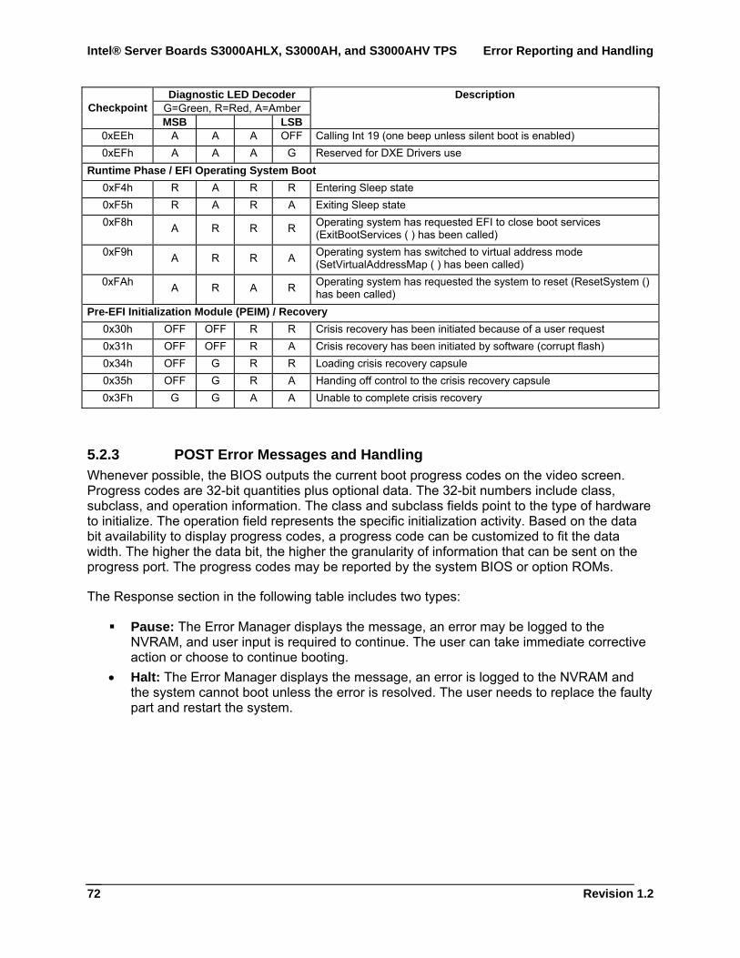
Intel® Server Boards S3000AHLX, S3000AH, and S3000AHV TPS Error Reporting and Handling
Revision 1.2
72
Diagnostic LED Decoder G=Green, R=Red, A=Amber Checkpoint MSB LSB
Description
0xEEh A A A OFF Calling Int 19 (one beep unless silent boot is enabled) 0xEFh A A A G Reserved for DXE Drivers use
Runtime Phase / EFI Operating System Boot 0xF4h R A R R Entering Sleep state 0xF5h R A R A Exiting Sleep state 0xF8h A R R R Operating system has requested EFI to close boot services
(ExitBootServices ( ) has been called) 0xF9h A R R A Operating system has switched to virtual address mode
(SetVirtualAddressMap ( ) has been called) 0xFAh A R A R Operating system has requested the system to reset (ResetSystem ()
has been called) Pre-EFI Initialization Module (PEIM) / Recovery
0x30h OFF OFF R R Crisis recovery has been initiated because of a user request 0x31h OFF OFF R A Crisis recovery has been initiated by software (corrupt flash) 0x34h OFF G R R Loading crisis recovery capsule 0x35h OFF G R A Handing off control to the crisis recovery capsule 0x3Fh G G A A Unable to complete crisis recovery
5.2.3 POST Error Messages and Handling Whenever possible, the BIOS outputs the current boot progress codes on the video screen. Progress codes are 32-bit quantities plus optional data. The 32-bit numbers include class, subclass, and operation information. The class and subclass fields point to the type of hardware to initialize. The operation field represents the specific initialization activity. Based on the data bit availability to display progress codes, a progress code can be customized to fit the data width. The higher the data bit, the higher the granularity of information that can be sent on the progress port. The progress codes may be reported by the system BIOS or option ROMs.
The Response section in the following table includes two types:
Pause: The Error Manager displays the message, an error may be logged to the NVRAM, and user input is required to continue. The user can take immediate corrective action or choose to continue booting.
• Halt: The Error Manager displays the message, an error is logged to the NVRAM and the system cannot boot unless the error is resolved. The user needs to replace the faulty part and restart the system.
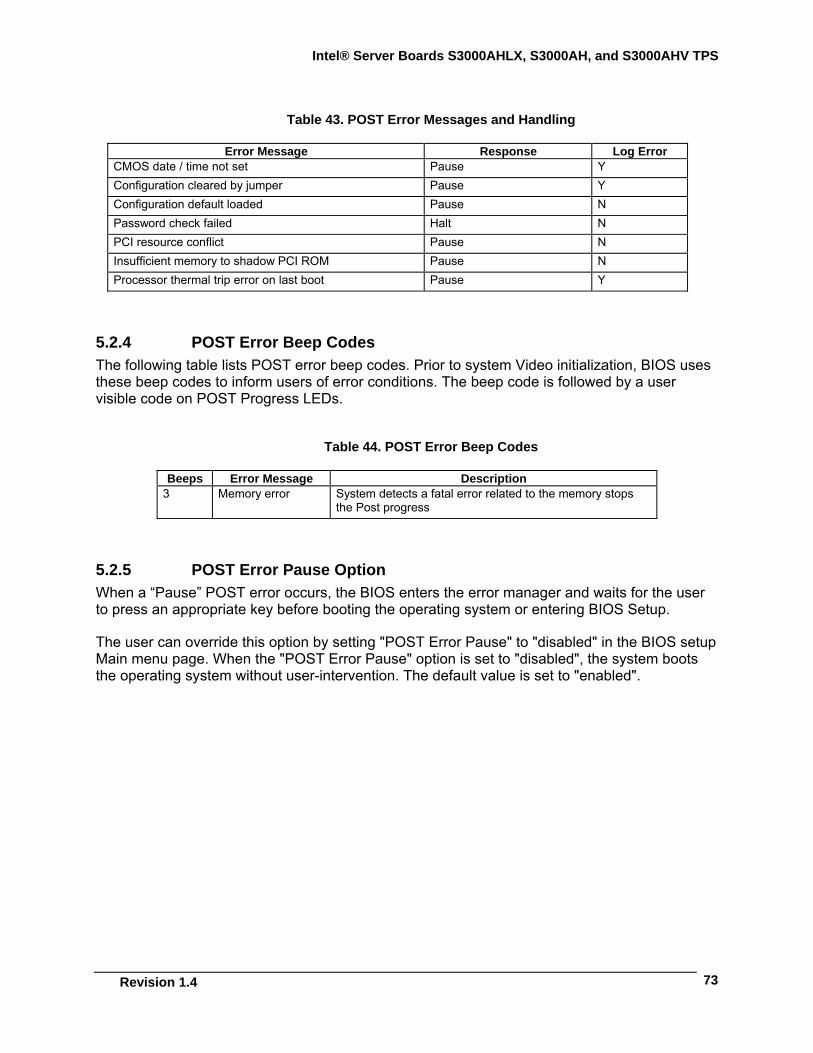
Intel® Server Boards S3000AHLX, S3000AH, and S3000AHV TPS
Revision 1.4
73
Table 43. POST Error Messages and Handling
Error Message Response Log Error CMOS date / time not set Pause Y Configuration cleared by jumper Pause Y Configuration default loaded Pause N Password check failed Halt N PCI resource conflict Pause N Insufficient memory to shadow PCI ROM Pause N Processor thermal trip error on last boot Pause Y
5.2.4 POST Error Beep Codes The following table lists POST error beep codes. Prior to system Video initialization, BIOS uses these beep codes to inform users of error conditions. The beep code is followed by a user visible code on POST Progress LEDs.
Table 44. POST Error Beep Codes
Beeps Error Message Description 3 Memory error System detects a fatal error related to the memory stops
the Post progress
5.2.5 POST Error Pause Option When a “Pause” POST error occurs, the BIOS enters the error manager and waits for the user to press an appropriate key before booting the operating system or entering BIOS Setup.
The user can override this option by setting "POST Error Pause" to "disabled" in the BIOS setup Main menu page. When the "POST Error Pause" option is set to "disabled", the system boots the operating system without user-intervention. The default value is set to "enabled".
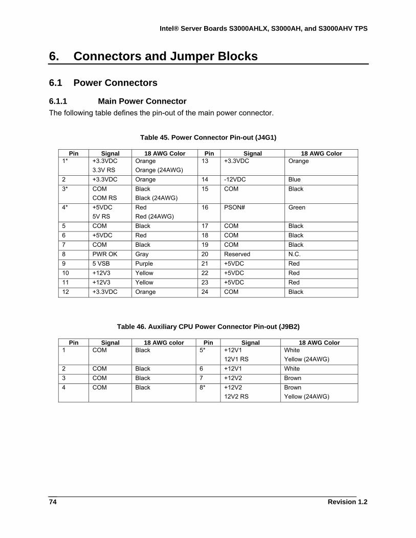
Intel® Server Boards S3000AHLX, S3000AH, and S3000AHV TPS
Revision 1.2
74
6. Connectors and Jumper Blocks
6.1 Power Connectors
6.1.1 Main Power Connector The following table defines the pin-out of the main power connector.
Table 45. Power Connector Pin-out (J4G1)
Pin Signal 18 AWG Color Pin Signal 18 AWG Color 1* +3.3VDC
3.3V RS Orange Orange (24AWG)
13 +3.3VDC Orange
2 +3.3VDC Orange 14 -12VDC Blue 3* COM
COM RS Black Black (24AWG)
15 COM Black
4* +5VDC 5V RS
Red Red (24AWG)
16 PSON# Green
5 COM Black 17 COM Black 6 +5VDC Red 18 COM Black 7 COM Black 19 COM Black 8 PWR OK Gray 20 Reserved N.C. 9 5 VSB Purple 21 +5VDC Red 10 +12V3 Yellow 22 +5VDC Red 11 +12V3 Yellow 23 +5VDC Red 12 +3.3VDC Orange 24 COM Black
Table 46. Auxiliary CPU Power Connector Pin-out (J9B2)
Pin Signal 18 AWG color Pin Signal 18 AWG Color 1 COM Black 5* +12V1
12V1 RS White Yellow (24AWG)
2 COM Black 6 +12V1 White 3 COM Black 7 +12V2 Brown 4 COM Black 8* +12V2
12V2 RS Brown Yellow (24AWG)
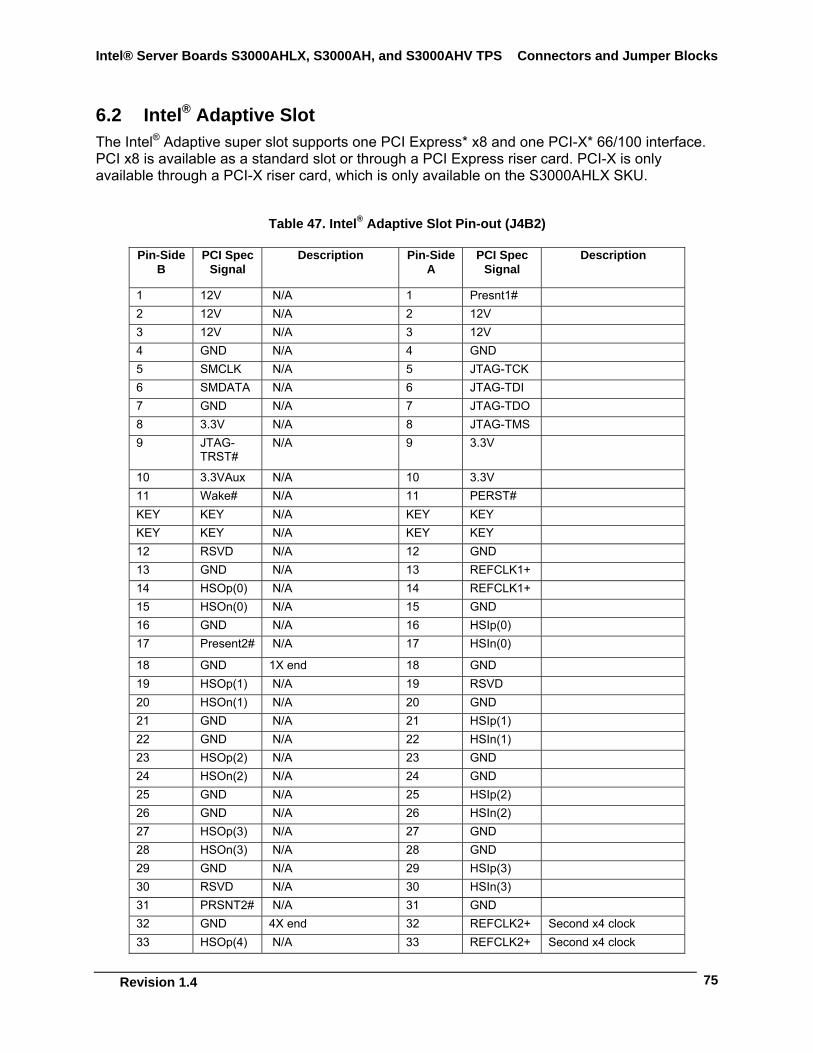
Intel® Server Boards S3000AHLX, S3000AH, and S3000AHV TPS Connectors and Jumper Blocks
Revision 1.4
75
6.2 Intel® Adaptive Slot The Intel® Adaptive super slot supports one PCI Express* x8 and one PCI-X* 66/100 interface. PCI x8 is available as a standard slot or through a PCI Express riser card. PCI-X is only available through a PCI-X riser card, which is only available on the S3000AHLX SKU.
Table 47. Intel® Adaptive Slot Pin-out (J4B2)
Pin-Side B
PCI Spec Signal
Description Pin-Side A
PCI Spec Signal
Description
1 12V N/A 1 Presnt1# 2 12V N/A 2 12V 3 12V N/A 3 12V 4 GND N/A 4 GND 5 SMCLK N/A 5 JTAG-TCK 6 SMDATA N/A 6 JTAG-TDI 7 GND N/A 7 JTAG-TDO 8 3.3V N/A 8 JTAG-TMS 9 JTAG-
TRST# N/A 9 3.3V
10 3.3VAux N/A 10 3.3V 11 Wake# N/A 11 PERST# KEY KEY N/A KEY KEY KEY KEY N/A KEY KEY 12 RSVD N/A 12 GND 13 GND N/A 13 REFCLK1+ 14 HSOp(0) N/A 14 REFCLK1+ 15 HSOn(0) N/A 15 GND 16 GND N/A 16 HSIp(0) 17 Present2# N/A 17 HSIn(0) 18 GND 1X end 18 GND 19 HSOp(1) N/A 19 RSVD 20 HSOn(1) N/A 20 GND 21 GND N/A 21 HSIp(1) 22 GND N/A 22 HSIn(1) 23 HSOp(2) N/A 23 GND 24 HSOn(2) N/A 24 GND 25 GND N/A 25 HSIp(2) 26 GND N/A 26 HSIn(2) 27 HSOp(3) N/A 27 GND 28 HSOn(3) N/A 28 GND 29 GND N/A 29 HSIp(3) 30 RSVD N/A 30 HSIn(3) 31 PRSNT2# N/A 31 GND 32 GND 4X end 32 REFCLK2+ Second x4 clock 33 HSOp(4) N/A 33 REFCLK2+ Second x4 clock
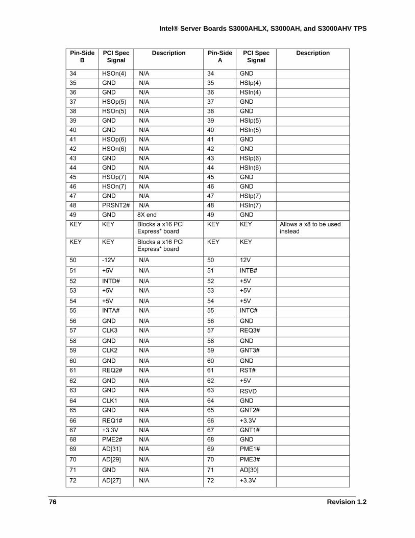
Intel® Server Boards S3000AHLX, S3000AH, and S3000AHV TPS
Revision 1.2
76
Pin-Side B
PCI Spec Signal
Description Pin-Side A
PCI Spec Signal
Description
34 HSOn(4) N/A 34 GND 35 GND N/A 35 HSIp(4) 36 GND N/A 36 HSIn(4) 37 HSOp(5) N/A 37 GND 38 HSOn(5) N/A 38 GND 39 GND N/A 39 HSIp(5) 40 GND N/A 40 HSIn(5) 41 HSOp(6) N/A 41 GND 42 HSOn(6) N/A 42 GND 43 GND N/A 43 HSIp(6) 44 GND N/A 44 HSIn(6) 45 HSOp(7) N/A 45 GND 46 HSOn(7) N/A 46 GND 47 GND N/A 47 HSIp(7) 48 PRSNT2# N/A 48 HSIn(7) 49 GND 8X end 49 GND KEY KEY Blocks a x16 PCI
Express* board KEY KEY Allows a x8 to be used
instead
KEY KEY Blocks a x16 PCI Express* board
KEY KEY
50 -12V N/A 50 12V 51 +5V N/A 51 INTB# 52 INTD# N/A 52 +5V 53 +5V N/A 53 +5V 54 +5V N/A 54 +5V 55 INTA# N/A 55 INTC# 56 GND N/A 56 GND 57 CLK3 N/A 57 REQ3# 58 GND N/A 58 GND 59 CLK2 N/A 59 GNT3# 60 GND N/A 60 GND 61 REQ2# N/A 61 RST# 62 GND N/A 62 +5V 63 GND N/A 63 RSVD 64 CLK1 N/A 64 GND 65 GND N/A 65 GNT2# 66 REQ1# N/A 66 +3.3V 67 +3.3V N/A 67 GNT1# 68 PME2# N/A 68 GND 69 AD[31] N/A 69 PME1# 70 AD[29] N/A 70 PME3# 71 GND N/A 71 AD[30] 72 AD[27] N/A 72 +3.3V
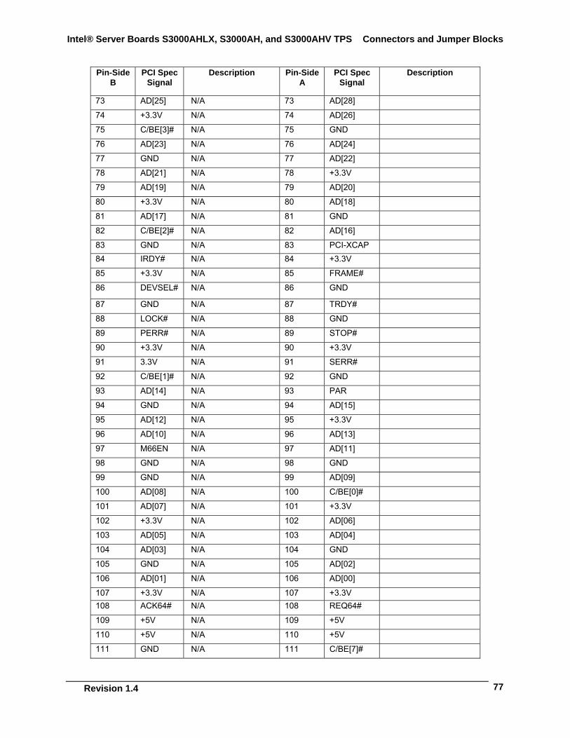
Intel® Server Boards S3000AHLX, S3000AH, and S3000AHV TPS Connectors and Jumper Blocks
Revision 1.4
77
Pin-Side B
PCI Spec Signal
Description Pin-Side A
PCI Spec Signal
Description
73 AD[25] N/A 73 AD[28] 74 +3.3V N/A 74 AD[26] 75 C/BE[3]# N/A 75 GND 76 AD[23] N/A 76 AD[24] 77 GND N/A 77 AD[22] 78 AD[21] N/A 78 +3.3V 79 AD[19] N/A 79 AD[20] 80 +3.3V N/A 80 AD[18] 81 AD[17] N/A 81 GND 82 C/BE[2]# N/A 82 AD[16] 83 GND N/A 83 PCI-XCAP 84 IRDY# N/A 84 +3.3V 85 +3.3V N/A 85 FRAME# 86 DEVSEL# N/A 86 GND 87 GND N/A 87 TRDY# 88 LOCK# N/A 88 GND 89 PERR# N/A 89 STOP# 90 +3.3V N/A 90 +3.3V 91 3.3V N/A 91 SERR# 92 C/BE[1]# N/A 92 GND 93 AD[14] N/A 93 PAR 94 GND N/A 94 AD[15] 95 AD[12] N/A 95 +3.3V 96 AD[10] N/A 96 AD[13] 97 M66EN N/A 97 AD[11] 98 GND N/A 98 GND 99 GND N/A 99 AD[09] 100 AD[08] N/A 100 C/BE[0]# 101 AD[07] N/A 101 +3.3V 102 +3.3V N/A 102 AD[06] 103 AD[05] N/A 103 AD[04] 104 AD[03] N/A 104 GND 105 GND N/A 105 AD[02] 106 AD[01] N/A 106 AD[00] 107 +3.3V N/A 107 +3.3V 108 ACK64# N/A 108 REQ64# 109 +5V N/A 109 +5V 110 +5V N/A 110 +5V 111 GND N/A 111 C/BE[7]#
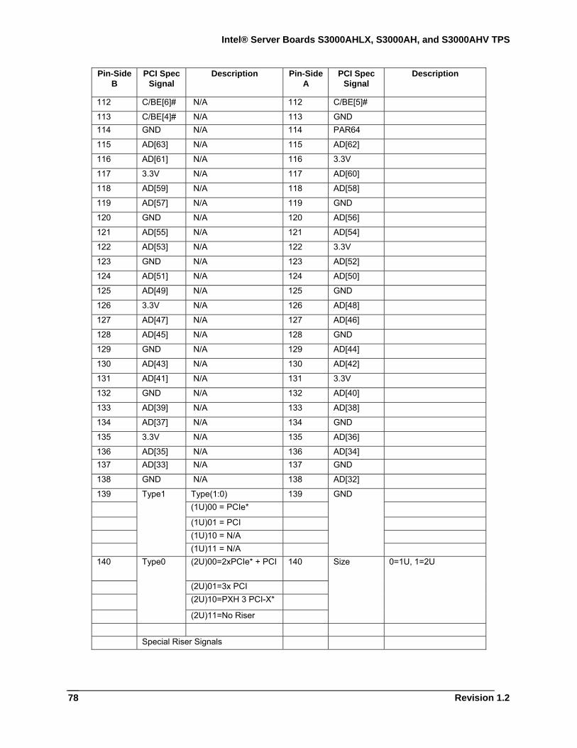
Intel® Server Boards S3000AHLX, S3000AH, and S3000AHV TPS
Revision 1.2
78
Pin-Side B
PCI Spec Signal
Description Pin-Side A
PCI Spec Signal
Description
112 C/BE[6]# N/A 112 C/BE[5]# 113 C/BE[4]# N/A 113 GND 114 GND N/A 114 PAR64 115 AD[63] N/A 115 AD[62] 116 AD[61] N/A 116 3.3V 117 3.3V N/A 117 AD[60] 118 AD[59] N/A 118 AD[58] 119 AD[57] N/A 119 GND 120 GND N/A 120 AD[56] 121 AD[55] N/A 121 AD[54] 122 AD[53] N/A 122 3.3V 123 GND N/A 123 AD[52] 124 AD[51] N/A 124 AD[50] 125 AD[49] N/A 125 GND 126 3.3V N/A 126 AD[48] 127 AD[47] N/A 127 AD[46] 128 AD[45] N/A 128 GND 129 GND N/A 129 AD[44] 130 AD[43] N/A 130 AD[42] 131 AD[41] N/A 131 3.3V 132 GND N/A 132 AD[40] 133 AD[39] N/A 133 AD[38] 134 AD[37] N/A 134 GND 135 3.3V N/A 135 AD[36] 136 AD[35] N/A 136 AD[34] 137 AD[33] N/A 137 GND 138 GND N/A 138 AD[32] 139 Type(1:0) 139 (1U)00 = PCIe* (1U)01 = PCI (1U)10 = N/A
Type1
(1U)11 = N/A
GND
140 (2U)00=2xPCIe* + PCI 140
(2U)01=3x PCI (2U)10=PXH 3 PCI-X*
Type0
(2U)11=No Riser
Size 0=1U, 1=2U
Special Riser Signals
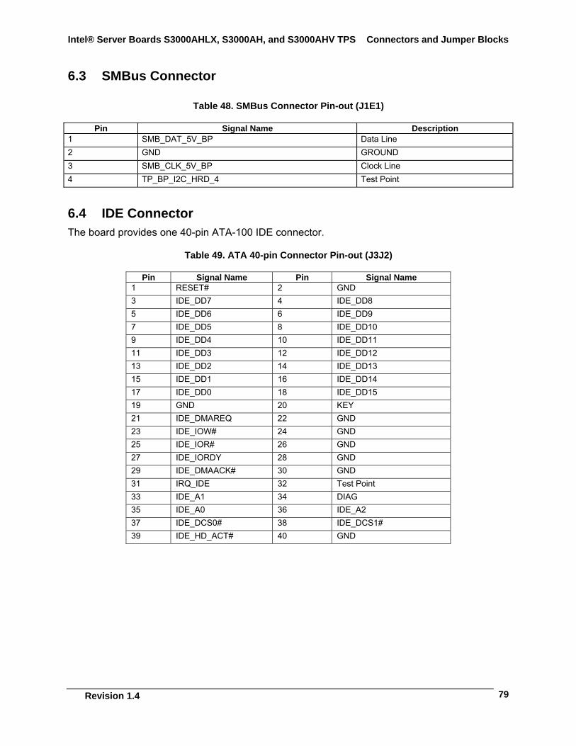
Intel® Server Boards S3000AHLX, S3000AH, and S3000AHV TPS Connectors and Jumper Blocks
Revision 1.4
79
6.3 SMBus Connector
Table 48. SMBus Connector Pin-out (J1E1)
Pin Signal Name Description 1 SMB_DAT_5V_BP Data Line 2 GND GROUND 3 SMB_CLK_5V_BP Clock Line 4 TP_BP_I2C_HRD_4 Test Point
6.4 IDE Connector The board provides one 40-pin ATA-100 IDE connector.
Table 49. ATA 40-pin Connector Pin-out (J3J2)
Pin Signal Name Pin Signal Name 1 RESET# 2 GND 3 IDE_DD7 4 IDE_DD8 5 IDE_DD6 6 IDE_DD9 7 IDE_DD5 8 IDE_DD10 9 IDE_DD4 10 IDE_DD11 11 IDE_DD3 12 IDE_DD12 13 IDE_DD2 14 IDE_DD13 15 IDE_DD1 16 IDE_DD14 17 IDE_DD0 18 IDE_DD15 19 GND 20 KEY 21 IDE_DMAREQ 22 GND 23 IDE_IOW# 24 GND 25 IDE_IOR# 26 GND 27 IDE_IORDY 28 GND 29 IDE_DMAACK# 30 GND 31 IRQ_IDE 32 Test Point 33 IDE_A1 34 DIAG 35 IDE_A0 36 IDE_A2 37 IDE_DCS0# 38 IDE_DCS1# 39 IDE_HD_ACT# 40 GND
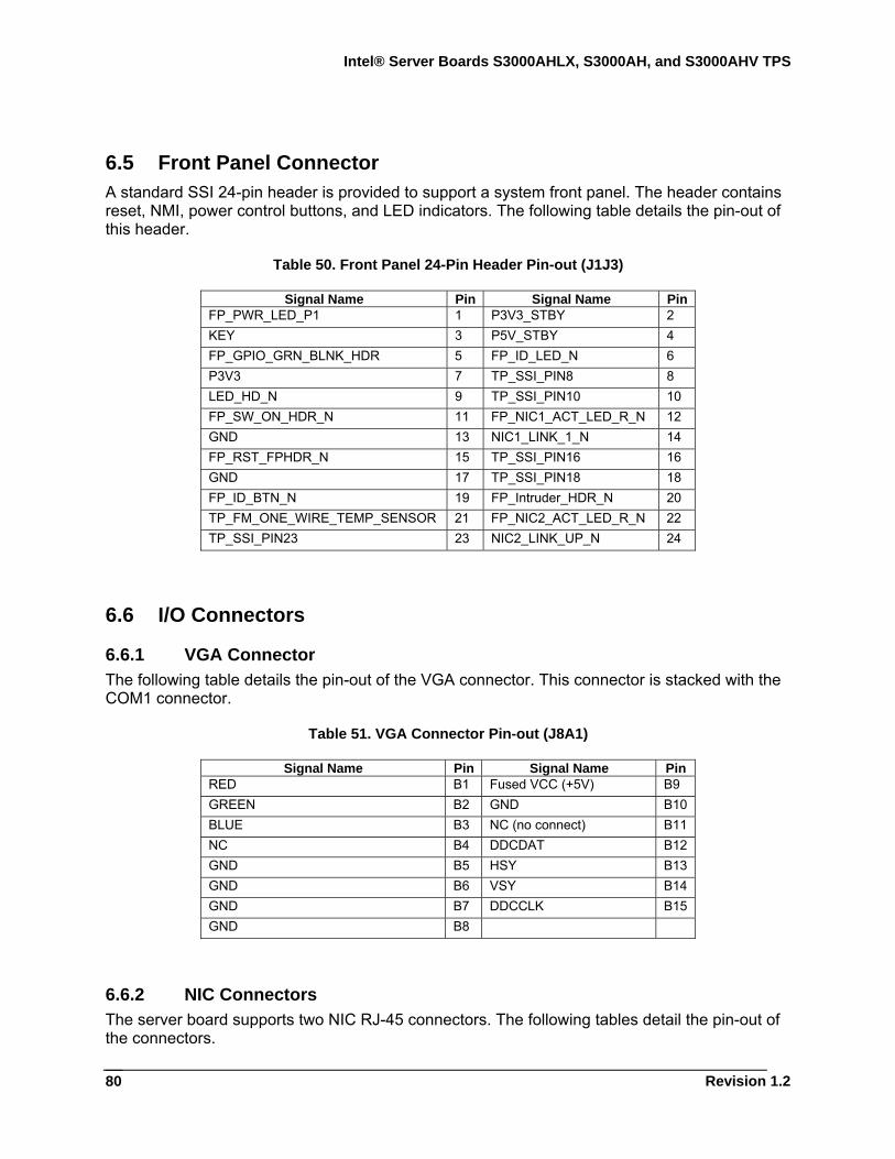
Intel® Server Boards S3000AHLX, S3000AH, and S3000AHV TPS
Revision 1.2
80
6.5 Front Panel Connector A standard SSI 24-pin header is provided to support a system front panel. The header contains reset, NMI, power control buttons, and LED indicators. The following table details the pin-out of this header.
Table 50. Front Panel 24-Pin Header Pin-out (J1J3)
Signal Name Pin Signal Name Pin FP_PWR_LED_P1 1 P3V3_STBY 2 KEY 3 P5V_STBY 4 FP_GPIO_GRN_BLNK_HDR 5 FP_ID_LED_N 6 P3V3 7 TP_SSI_PIN8 8 LED_HD_N 9 TP_SSI_PIN10 10 FP_SW_ON_HDR_N 11 FP_NIC1_ACT_LED_R_N 12 GND 13 NIC1_LINK_1_N 14 FP_RST_FPHDR_N 15 TP_SSI_PIN16 16 GND 17 TP_SSI_PIN18 18 FP_ID_BTN_N 19 FP_Intruder_HDR_N 20 TP_FM_ONE_WIRE_TEMP_SENSOR 21 FP_NIC2_ACT_LED_R_N 22 TP_SSI_PIN23 23 NIC2_LINK_UP_N 24
6.6 I/O Connectors
6.6.1 VGA Connector The following table details the pin-out of the VGA connector. This connector is stacked with the COM1 connector.
Table 51. VGA Connector Pin-out (J8A1)
Signal Name Pin Signal Name Pin RED B1 Fused VCC (+5V) B9 GREEN B2 GND B10 BLUE B3 NC (no connect) B11 NC B4 DDCDAT B12 GND B5 HSY B13 GND B6 VSY B14 GND B7 DDCCLK B15 GND B8
6.6.2 NIC Connectors The server board supports two NIC RJ-45 connectors. The following tables detail the pin-out of the connectors.
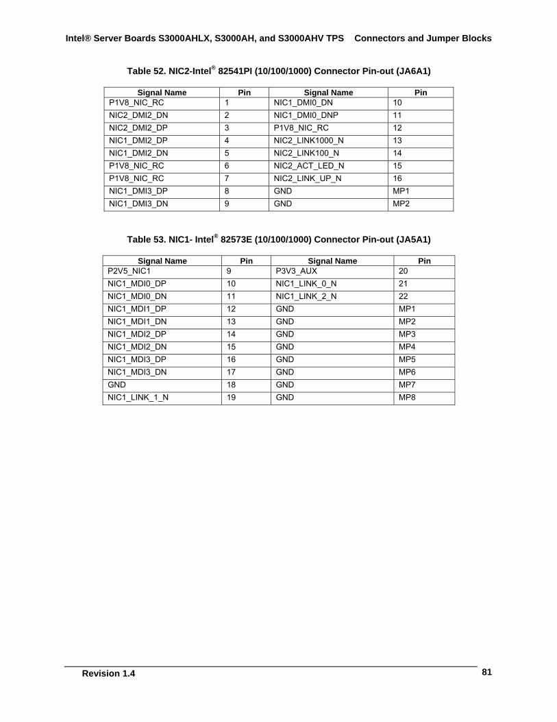
Intel® Server Boards S3000AHLX, S3000AH, and S3000AHV TPS Connectors and Jumper Blocks
Revision 1.4
81
Table 52. NIC2-Intel® 82541PI (10/100/1000) Connector Pin-out (JA6A1)
Signal Name Pin Signal Name Pin P1V8_NIC_RC 1 NIC1_DMI0_DN 10 NIC2_DMI2_DN 2 NIC1_DMI0_DNP 11 NIC2_DMI2_DP 3 P1V8_NIC_RC 12 NIC1_DMI2_DP 4 NIC2_LINK1000_N 13 NIC1_DMI2_DN 5 NIC2_LINK100_N 14 P1V8_NIC_RC 6 NIC2_ACT_LED_N 15 P1V8_NIC_RC 7 NIC2_LINK_UP_N 16 NIC1_DMI3_DP 8 GND MP1 NIC1_DMI3_DN 9 GND MP2
Table 53. NIC1- Intel® 82573E (10/100/1000) Connector Pin-out (JA5A1)
Signal Name Pin Signal Name Pin P2V5_NIC1 9 P3V3_AUX 20 NIC1_MDI0_DP 10 NIC1_LINK_0_N 21 NIC1_MDI0_DN 11 NIC1_LINK_2_N 22 NIC1_MDI1_DP 12 GND MP1 NIC1_MDI1_DN 13 GND MP2 NIC1_MDI2_DP 14 GND MP3 NIC1_MDI2_DN 15 GND MP4 NIC1_MDI3_DP 16 GND MP5 NIC1_MDI3_DN 17 GND MP6 GND 18 GND MP7 NIC1_LINK_1_N 19 GND MP8
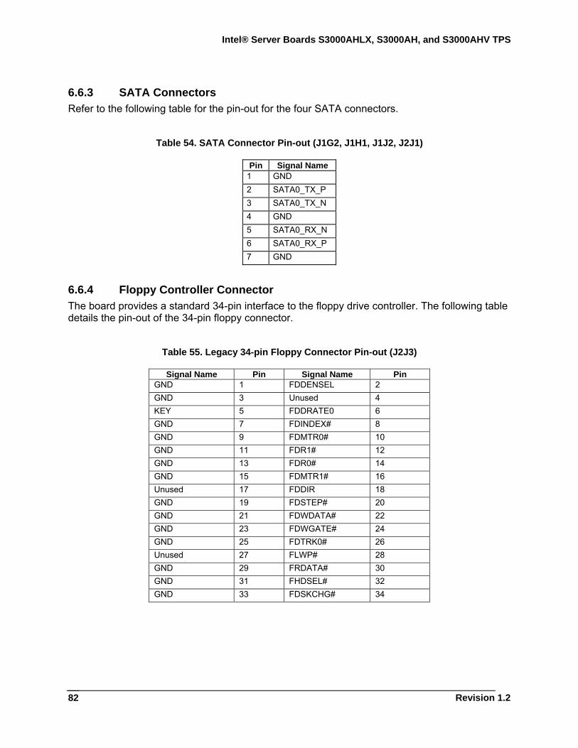
Intel® Server Boards S3000AHLX, S3000AH, and S3000AHV TPS
Revision 1.2
82
6.6.3 SATA Connectors Refer to the following table for the pin-out for the four SATA connectors.
Table 54. SATA Connector Pin-out (J1G2, J1H1, J1J2, J2J1)
Pin Signal Name 1 GND 2 SATA0_TX_P 3 SATA0_TX_N 4 GND 5 SATA0_RX_N 6 SATA0_RX_P 7 GND
6.6.4 Floppy Controller Connector The board provides a standard 34-pin interface to the floppy drive controller. The following table details the pin-out of the 34-pin floppy connector.
Table 55. Legacy 34-pin Floppy Connector Pin-out (J2J3)
Signal Name Pin Signal Name Pin GND 1 FDDENSEL 2 GND 3 Unused 4 KEY 5 FDDRATE0 6 GND 7 FDINDEX# 8 GND 9 FDMTR0# 10 GND 11 FDR1# 12 GND 13 FDR0# 14 GND 15 FDMTR1# 16 Unused 17 FDDIR 18 GND 19 FDSTEP# 20 GND 21 FDWDATA# 22 GND 23 FDWGATE# 24 GND 25 FDTRK0# 26 Unused 27 FLWP# 28 GND 29 FRDATA# 30 GND 31 FHDSEL# 32 GND 33 FDSKCHG# 34
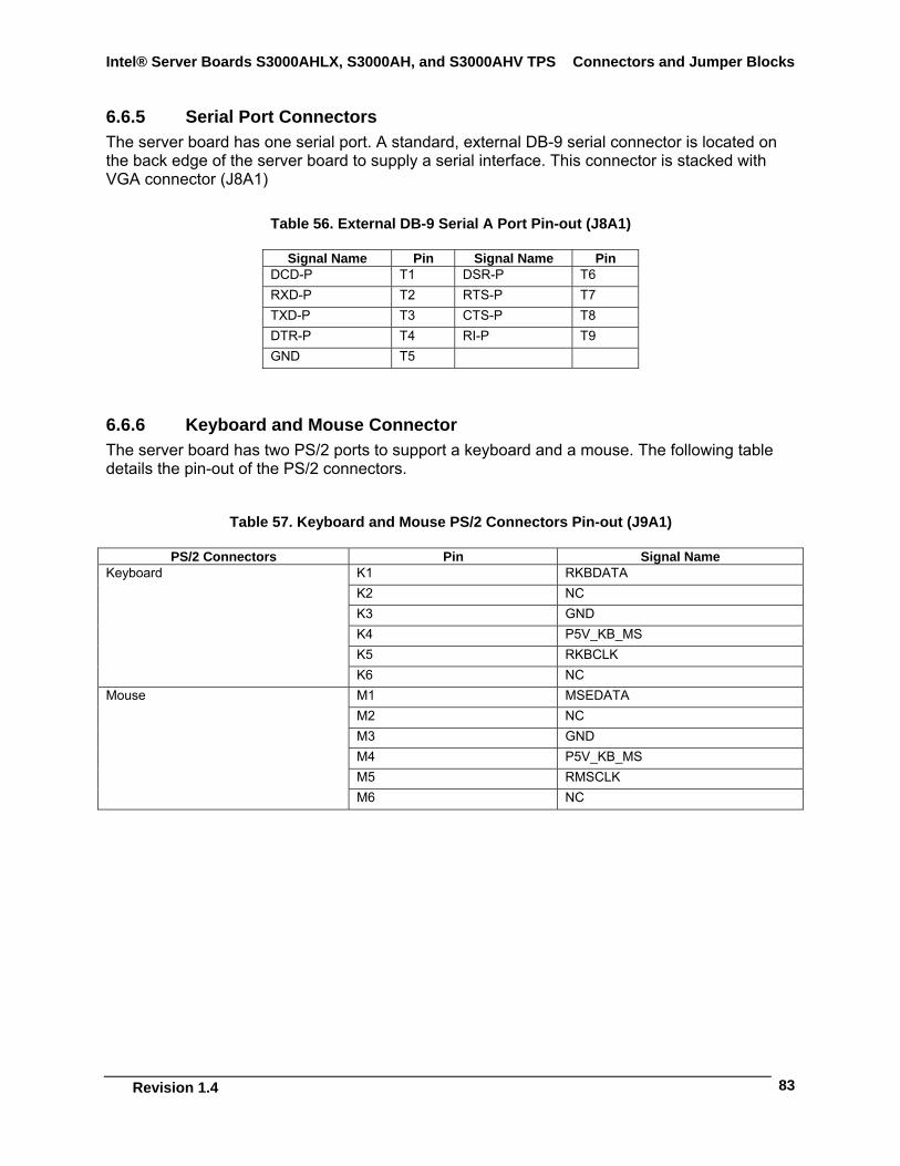
Intel® Server Boards S3000AHLX, S3000AH, and S3000AHV TPS Connectors and Jumper Blocks
Revision 1.4
83
6.6.5 Serial Port Connectors The server board has one serial port. A standard, external DB-9 serial connector is located on the back edge of the server board to supply a serial interface. This connector is stacked with VGA connector (J8A1)
Table 56. External DB-9 Serial A Port Pin-out (J8A1)
Signal Name Pin Signal Name Pin DCD-P T1 DSR-P T6 RXD-P T2 RTS-P T7 TXD-P T3 CTS-P T8 DTR-P T4 RI-P T9 GND T5
6.6.6 Keyboard and Mouse Connector The server board has two PS/2 ports to support a keyboard and a mouse. The following table details the pin-out of the PS/2 connectors.
Table 57. Keyboard and Mouse PS/2 Connectors Pin-out (J9A1)
PS/2 Connectors Pin Signal Name K1 RKBDATA K2 NC K3 GND K4 P5V_KB_MS K5 RKBCLK
Keyboard
K6 NC M1 MSEDATA M2 NC M3 GND M4 P5V_KB_MS M5 RMSCLK
Mouse
M6 NC
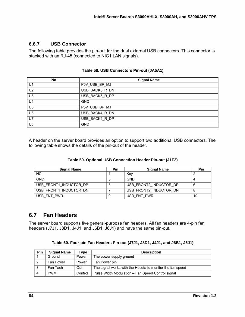
Intel® Server Boards S3000AHLX, S3000AH, and S3000AHV TPS
Revision 1.2
84
6.6.7 USB Connector The following table provides the pin-out for the dual external USB connectors. This connector is stacked with an RJ-45 (connected to NIC1 LAN signals).
Table 58. USB Connectors Pin-out (JA5A1)
Pin Signal Name U1 P5V_USB_BP_MJ U2 USB_BACK5_R_DN U3 USB_BACK5_R_DP U4 GND U5 P5V_USB_BP_MJ U6 USB_BACK4_R_DN U7 USB_BACK4_R_DP U8 GND
A header on the server board provides an option to support two additional USB connectors. The following table shows the details of the pin-out of the header.
Table 59. Optional USB Connection Header Pin-out (J1F2)
Signal Name Pin Signal Name Pin NC 1 Key 2 GND 3 GND 4 USB_FRONT1_INDUCTOR_DP 5 USB_FRONT2_INDUCTOR_DP 6 USB_FRONT1_INDUCTOR_DN 7 USB_FRONT2_INDUCTOR_DN 8 USB_FNT_PWR 9 USB_FNT_PWR 10
6.7 Fan Headers The server board supports five general-purpose fan headers. All fan headers are 4-pin fan headers (J7J1, J8D1, J4J1, and J6B1, J6J1) and have the same pin-out.
Table 60. Four-pin Fan Headers Pin-out (J7J1, J8D1, J4J1, and J6B1, J6J1)
Pin Signal Name Type Description 1 Ground Power The power supply ground 2 Fan Power Power Fan Power pin 3 Fan Tach Out The signal works with the Heceta to monitor the fan speed 4 PWM Control Pulse Width Modulation – Fan Speed Control signal
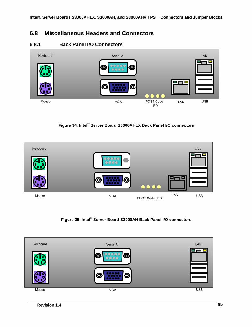
Intel® Server Boards S3000AHLX, S3000AH, and S3000AHV TPS Connectors and Jumper Blocks
Revision 1.4
85
6.8 Miscellaneous Headers and Connectors
6.8.1 Back Panel I/O Connectors
Figure 34. Intel® Server Board S3000AHLX Back Panel I/O connectors
Figure 35. Intel® Server Board S3000AH Back Panel I/O connectors
Mouse
Serial A
VGA USB
Keyboard
LAN
LAN
POST Code LED
Keyboard
LAN
LAN
Mouse
Serial A
VGA USBPOST Code LED
Keyboard
LAN
Mouse
Serial A
VGA USB
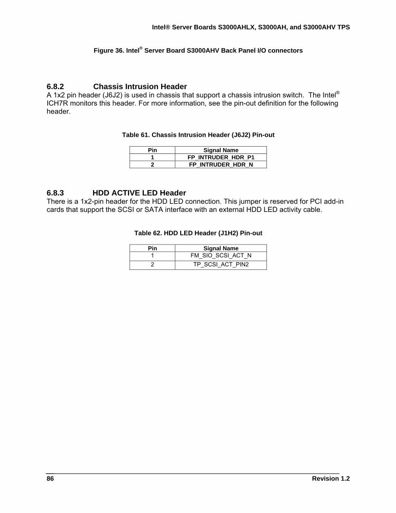
Intel® Server Boards S3000AHLX, S3000AH, and S3000AHV TPS
Revision 1.2
86
Figure 36. Intel® Server Board S3000AHV Back Panel I/O connectors
6.8.2 Chassis Intrusion Header A 1x2 pin header (J6J2) is used in chassis that support a chassis intrusion switch. The Intel® ICH7R monitors this header. For more information, see the pin-out definition for the following header.
Table 61. Chassis Intrusion Header (J6J2) Pin-out
Pin Signal Name 1 FP_INTRUDER_HDR_P1 2 FP_INTRUDER_HDR_N
6.8.3 HDD ACTIVE LED Header There is a 1x2-pin header for the HDD LED connection. This jumper is reserved for PCI add-in cards that support the SCSI or SATA interface with an external HDD LED activity cable.
Table 62. HDD LED Header (J1H2) Pin-out
Pin Signal Name 1 FM_SIO_SCSI_ACT_N 2 TP_SCSI_ACT_PIN2
Intel® Server Boards S3000AHLX, S3000AH, and S3000AHV TPS Connectors and Jumper Blocks
Revision 1.4
87
6.9 Jumper Blocks This section describes the configuration jumper options on the server board.
6.9.1 NIC1 NVM Protect The server board provides a 3-pin jumper block to perform Intel® 82573E firmware protected and unprotected options. The factory default is set to protected mode. Refer to the following table for the pin-out options.
Table 63. NIC1 NVM Protect Mode (J4A1)
6.9.2 Clear CMOS and System Maintenance Mode Jumpers Both the CMOS Clear and the System Maintenance Mode jumpers consist of 3-pin headers (CMOS Clear = J1G3, Maintenance Mode = J1H3) located just beside the front panel and SATA 1 connectors. The server board provides two 3-pin jumper blocks to clear the NVRAM, system BIOS recovery, and system maintenance mode options. The factory defaults are set to normal mode for each function.
The following tables describe each jumper option.
Table 64. System Maintenance Mode (J1H3)
Name Pin – Pin Function Description
Default 1-2 Protected The default jumper position does not allow the Intel® 82573E firmware to be programmed.
Update 2-3 Unprotected The update jumper position allows the Intel® 82573E firmware to be programmed.
Name Pin – Pin Function Description
Normal 1-2 Normal Operation Allows normal system operation with correct BIOS settings. System will POST normally.
Maintenance Mode 2-3 Maintenance Mode Intel® AMT setting/password reset.
Recovery Boot Off BIOS Recovery Mode Used to recover the system when the BIOS is corrupted. Bootable media with a valid BIOS ROM is required.
Intel® Server Boards S3000AHLX, S3000AH, and S3000AHV TPS
Revision 1.2
88
Table 65. Clear CMOS Jumper Options (J1G3)
6.9.3 SPI/FWH Selection Header
Table 66. SPI/FWH Selection Header (J1F1)
Name Pin – Pin Function Description
Normal 1-2 Normal Operation
Jumper in normal position allows system to successfully POST and boot to the operating system environment. BIOS settings remain intact.
CMOS Clear 2-3 Clears CMOS (NVRAM)
Jumper in clear position clears CMOS following POST. A system message confirms the CMOS/NVRAM clear operation was successful. This setting enforces default BIOS settings. Select <F2> to enter setup and change the settings. Exit setup by selecting <F10> and saving changes.
Name Pin – Pin Function Description
Default 1-2 Select SPI The jumper should always be connected on the default pins
FWH 2-3 Select FWH The FWH part is removed In production boards
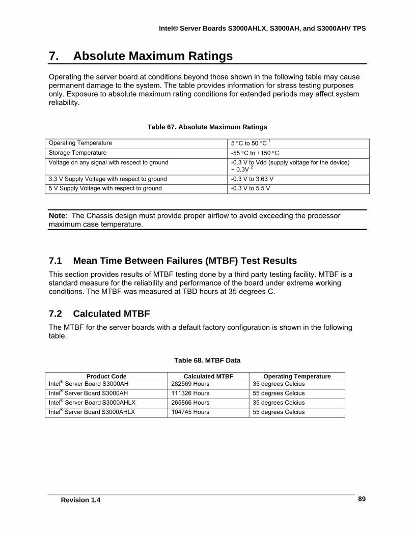
Intel® Server Boards S3000AHLX, S3000AH, and S3000AHV TPS
Revision 1.4
89
7. Absolute Maximum Ratings Operating the server board at conditions beyond those shown in the following table may cause permanent damage to the system. The table provides information for stress testing purposes only. Exposure to absolute maximum rating conditions for extended periods may affect system reliability.
Table 67. Absolute Maximum Ratings
Operating Temperature 5 °C to 50 °C 1 Storage Temperature -55 °C to +150 °C Voltage on any signal with respect to ground -0.3 V to Vdd (supply voltage for the device)
+ 0.3V 2 3.3 V Supply Voltage with respect to ground -0.3 V to 3.63 V 5 V Supply Voltage with respect to ground -0.3 V to 5.5 V
Note: The Chassis design must provide proper airflow to avoid exceeding the processor maximum case temperature.
7.1 Mean Time Between Failures (MTBF) Test Results This section provides results of MTBF testing done by a third party testing facility. MTBF is a standard measure for the reliability and performance of the board under extreme working conditions. The MTBF was measured at TBD hours at 35 degrees C.
7.2 Calculated MTBF The MTBF for the server boards with a default factory configuration is shown in the following table.
Table 68. MTBF Data
Product Code Calculated MTBF Operating Temperature Intel® Server Board S3000AH 282569 Hours 35 degrees Celcius Intel® Server Board S3000AH 111326 Hours 55 degrees Celcius Intel® Server Board S3000AHLX 265866 Hours 35 degrees Celcius Intel® Server Board S3000AHLX 104745 Hours 55 degrees Celcius
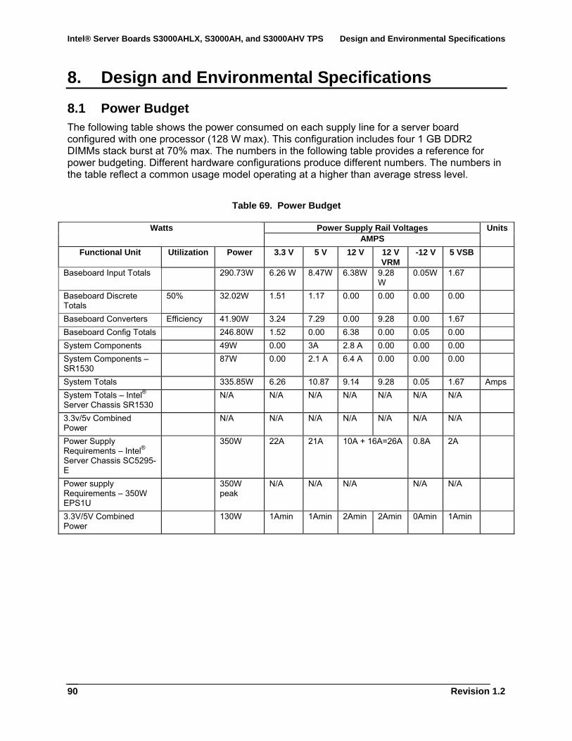
Intel® Server Boards S3000AHLX, S3000AH, and S3000AHV TPS Design and Environmental Specifications
Revision 1.2
90
8. Design and Environmental Specifications
8.1 Power Budget The following table shows the power consumed on each supply line for a server board configured with one processor (128 W max). This configuration includes four 1 GB DDR2 DIMMs stack burst at 70% max. The numbers in the following table provides a reference for power budgeting. Different hardware configurations produce different numbers. The numbers in the table reflect a common usage model operating at a higher than average stress level.
Table 69. Power Budget
Power Supply Rail Voltages Watts AMPS
Units
Functional Unit Utilization Power 3.3 V 5 V 12 V 12 V VRM
-12 V 5 VSB
Baseboard Input Totals 290.73W 6.26 W 8.47W 6.38W 9.28 W
0.05W 1.67
Baseboard Discrete Totals
50% 32.02W 1.51 1.17 0.00 0.00 0.00 0.00
Baseboard Converters Efficiency 41.90W 3.24 7.29 0.00 9.28 0.00 1.67 Baseboard Config Totals 246.80W 1.52 0.00 6.38 0.00 0.05 0.00 System Components 49W 0.00 3A 2.8 A 0.00 0.00 0.00 System Components – SR1530
87W 0.00 2.1 A 6.4 A 0.00 0.00 0.00
System Totals 335.85W 6.26 10.87 9.14 9.28 0.05 1.67 Amps System Totals – Intel® Server Chassis SR1530
N/A N/A N/A N/A N/A N/A N/A
3.3v/5v Combined Power
N/A N/A N/A N/A N/A N/A N/A
Power Supply Requirements – Intel® Server Chassis SC5295-E
350W 22A 21A 10A + 16A=26A 0.8A 2A
Power supply Requirements – 350W EPS1U
350W peak
N/A N/A N/A N/A N/A
3.3V/5V Combined Power
130W 1Amin 1Amin 2Amin 2Amin 0Amin 1Amin
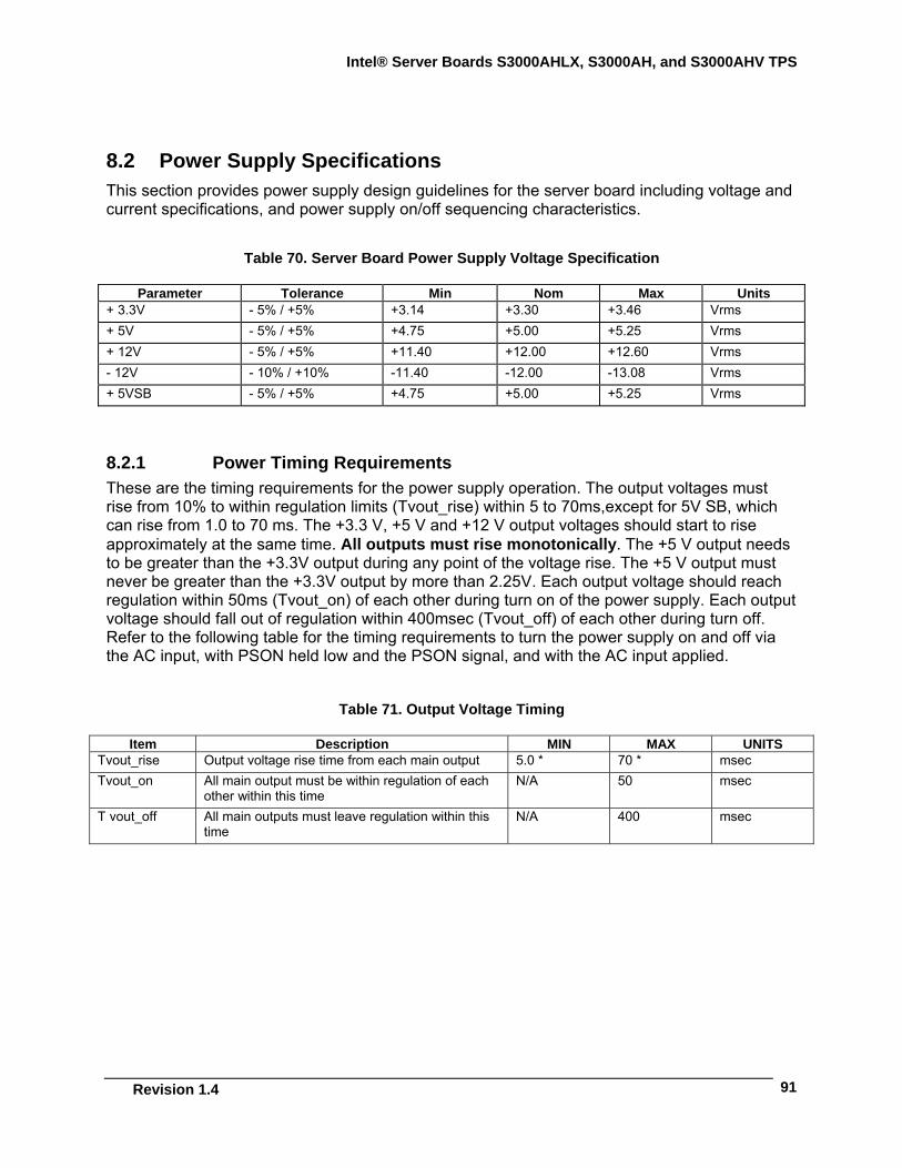
Intel® Server Boards S3000AHLX, S3000AH, and S3000AHV TPS
Revision 1.4
91
8.2 Power Supply Specifications This section provides power supply design guidelines for the server board including voltage and current specifications, and power supply on/off sequencing characteristics.
Table 70. Server Board Power Supply Voltage Specification
Parameter Tolerance Min Nom Max Units + 3.3V - 5% / +5% +3.14 +3.30 +3.46 Vrms + 5V - 5% / +5% +4.75 +5.00 +5.25 Vrms + 12V - 5% / +5% +11.40 +12.00 +12.60 Vrms - 12V - 10% / +10% -11.40 -12.00 -13.08 Vrms + 5VSB - 5% / +5% +4.75 +5.00 +5.25 Vrms
8.2.1 Power Timing Requirements These are the timing requirements for the power supply operation. The output voltages must rise from 10% to within regulation limits (Tvout_rise) within 5 to 70ms,except for 5V SB, which can rise from 1.0 to 70 ms. The +3.3 V, +5 V and +12 V output voltages should start to rise approximately at the same time. All outputs must rise monotonically. The +5 V output needs to be greater than the +3.3V output during any point of the voltage rise. The +5 V output must never be greater than the +3.3V output by more than 2.25V. Each output voltage should reach regulation within 50ms (Tvout_on) of each other during turn on of the power supply. Each output voltage should fall out of regulation within 400msec (Tvout_off) of each other during turn off. Refer to the following table for the timing requirements to turn the power supply on and off via the AC input, with PSON held low and the PSON signal, and with the AC input applied.
Table 71. Output Voltage Timing
Item Description MIN MAX UNITS Tvout_rise Output voltage rise time from each main output 5.0 * 70 * msec Tvout_on All main output must be within regulation of each
other within this time N/A 50 msec
T vout_off All main outputs must leave regulation within this time
N/A 400 msec
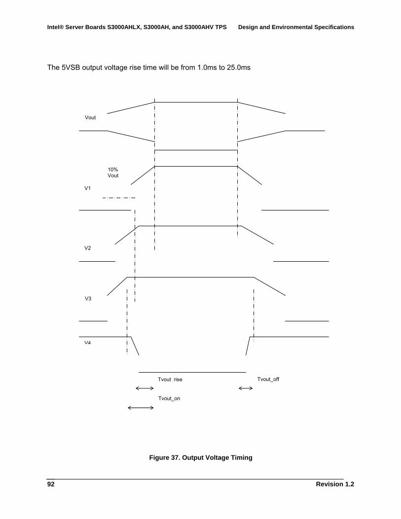
Intel® Server Boards S3000AHLX, S3000AH, and S3000AHV TPS Design and Environmental Specifications
Revision 1.2
92
The 5VSB output voltage rise time will be from 1.0ms to 25.0ms
Figure 37. Output Voltage Timing
Vout
10% Vout
Tvout_rise
Tvout_on
Tvout_off
V1
V2
V3
V4
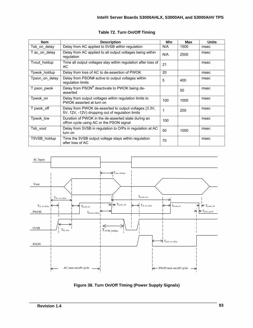
Intel® Server Boards S3000AHLX, S3000AH, and S3000AHV TPS
Revision 1.4
93
Table 72. Turn On/Off Timing
Item Description Min Max Units Tsb_on_delay Delay from AC applied to 5VSB within regulation N/A 1500 msec T ac_on_delay Delay from AC applied to all output voltages being within
regulation N/A 2500 msec
Tvout_holdup Time all output voltages stay within regulation after loss of AC 21 msec
Tpwok_holdup Delay from loss of AC to de-assertion of PWOK 20 msec Tpson_on_delay Delay from PSON# active to output voltages within
regulation limits 5 400 msec
T pson_pwok Delay from PSON# deactivate to PWOK being de-asserted 50 msec
Tpwok_on Delay from output voltages within regulation limits to PWOK asserted at turn on 100 1000 msec
T pwok_off Delay from PWOK de-asserted to output voltages (3.3V, 5V, 12V, -12V) dropping out of regulation limits 1 200 msec
Tpwok_low Duration of PWOK in the de-asserted state during an off/on cycle using AC or the PSON signal 100 msec
Tsb_vout Delay from 5VSB in regulation to O/Ps in regulation at AC turn on 50 1000 msec
T5VSB_holdup Time the 5VSB output voltage stays within regulation after loss of AC 70 msec
AC Input
Vout
PWOK
5VSB
PSON
T sb_on_delay
T AC_on_delay T pwok_on
Tvout_holdup
T pwok_holdup
Tpson_on_delay
Tsb_on_delay Tpwok_on Tpwok_off Tpwok_off
Tpson_pwok
Tpwok_low
T sb_vout
AC turn on/off cycle PSON turn on/off cycle
T5VSB_holdup
Figure 38. Turn On/Off Timing (Power Supply Signals)
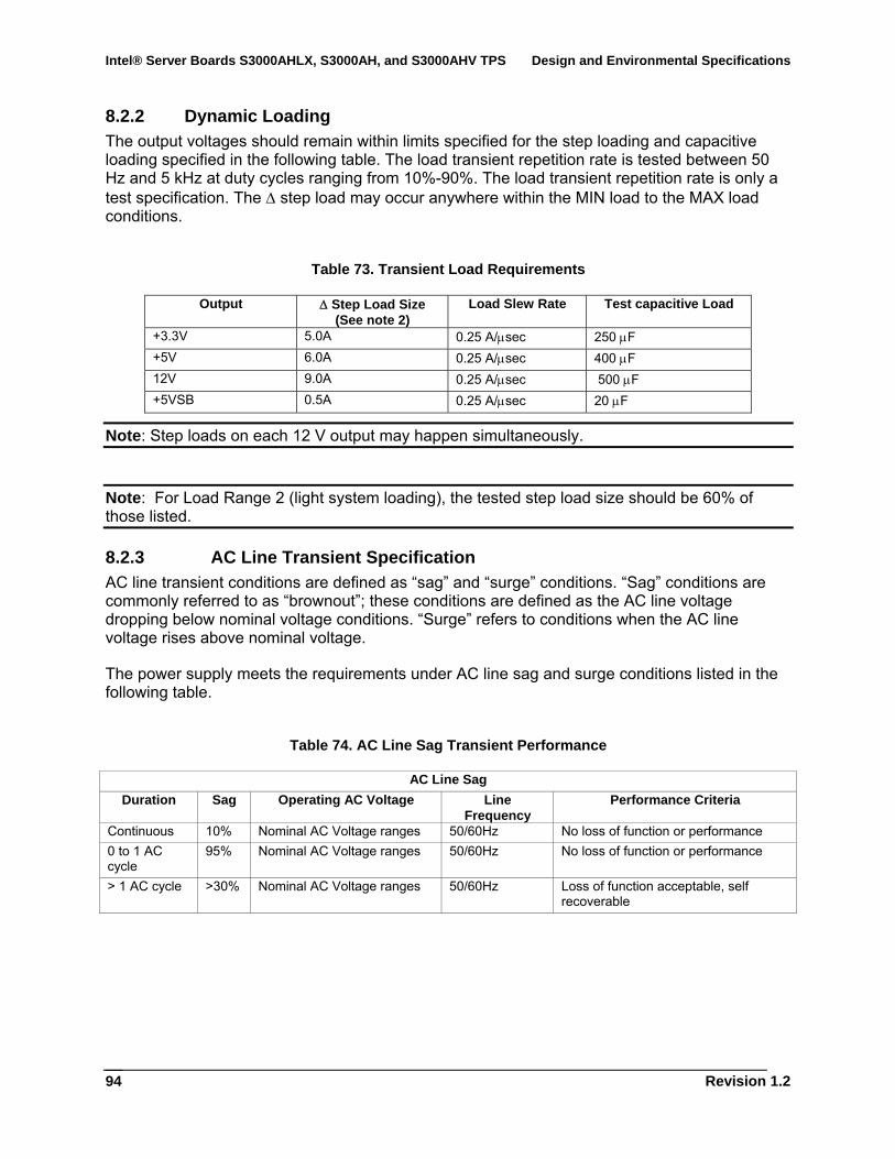
Intel® Server Boards S3000AHLX, S3000AH, and S3000AHV TPS Design and Environmental Specifications
Revision 1.2
94
8.2.2 Dynamic Loading The output voltages should remain within limits specified for the step loading and capacitive loading specified in the following table. The load transient repetition rate is tested between 50 Hz and 5 kHz at duty cycles ranging from 10%-90%. The load transient repetition rate is only a test specification. The Δ step load may occur anywhere within the MIN load to the MAX load conditions.
Table 73. Transient Load Requirements
Output Δ Step Load Size (See note 2)
Load Slew Rate Test capacitive Load
+3.3V 5.0A 0.25 A/μsec 250 μF +5V 6.0A 0.25 A/μsec 400 μF 12V 9.0A 0.25 A/μsec 500 μF +5VSB 0.5A 0.25 A/μsec 20 μF
Note: Step loads on each 12 V output may happen simultaneously.
Note: For Load Range 2 (light system loading), the tested step load size should be 60% of those listed.
8.2.3 AC Line Transient Specification AC line transient conditions are defined as “sag” and “surge” conditions. “Sag” conditions are commonly referred to as “brownout”; these conditions are defined as the AC line voltage dropping below nominal voltage conditions. “Surge” refers to conditions when the AC line voltage rises above nominal voltage.
The power supply meets the requirements under AC line sag and surge conditions listed in the following table.
Table 74. AC Line Sag Transient Performance
AC Line Sag Duration Sag Operating AC Voltage Line
Frequency Performance Criteria
Continuous 10% Nominal AC Voltage ranges 50/60Hz No loss of function or performance 0 to 1 AC cycle
95% Nominal AC Voltage ranges 50/60Hz No loss of function or performance
> 1 AC cycle >30% Nominal AC Voltage ranges 50/60Hz Loss of function acceptable, self recoverable
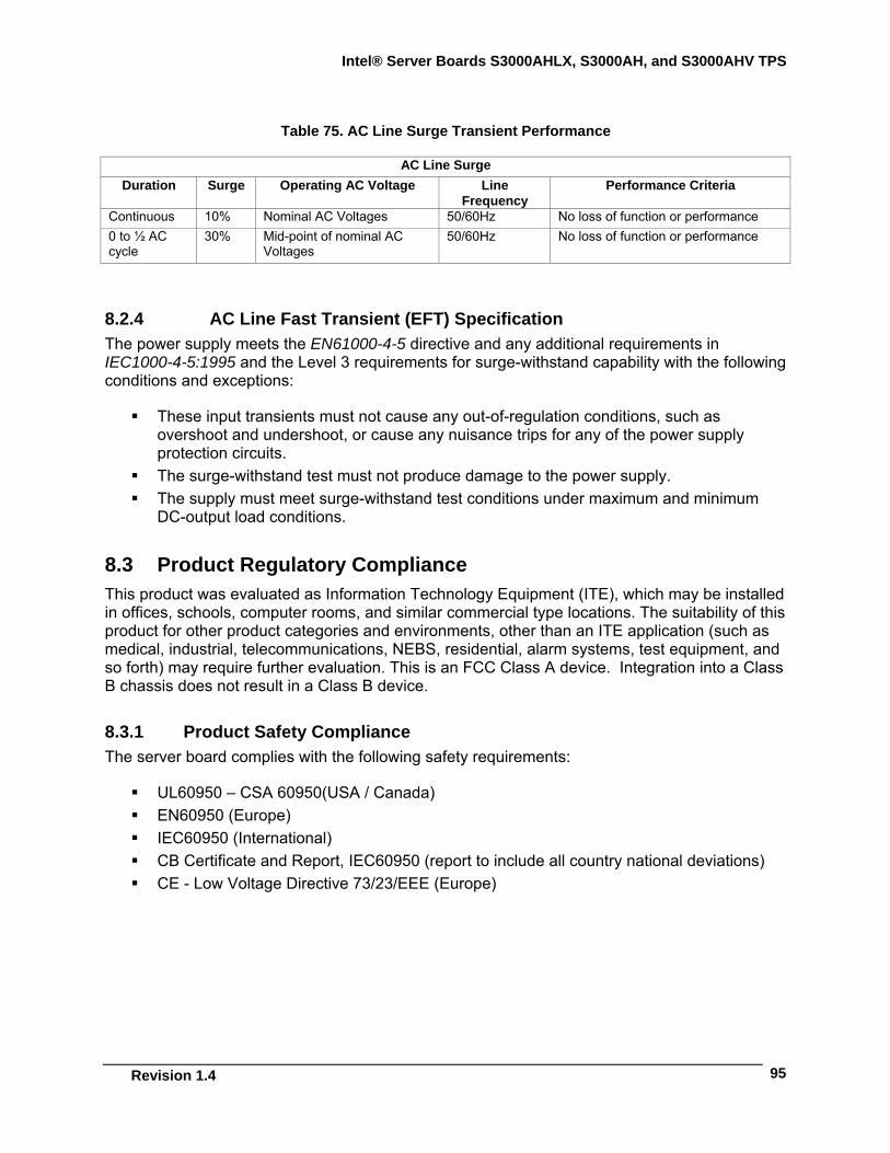
Intel® Server Boards S3000AHLX, S3000AH, and S3000AHV TPS
Revision 1.4
95
Table 75. AC Line Surge Transient Performance
AC Line Surge Duration Surge Operating AC Voltage Line
Frequency Performance Criteria
Continuous 10% Nominal AC Voltages 50/60Hz No loss of function or performance 0 to ½ AC cycle
30% Mid-point of nominal AC Voltages
50/60Hz No loss of function or performance
8.2.4 AC Line Fast Transient (EFT) Specification The power supply meets the EN61000-4-5 directive and any additional requirements in IEC1000-4-5:1995 and the Level 3 requirements for surge-withstand capability with the following conditions and exceptions:
These input transients must not cause any out-of-regulation conditions, such as overshoot and undershoot, or cause any nuisance trips for any of the power supply protection circuits.
The surge-withstand test must not produce damage to the power supply. The supply must meet surge-withstand test conditions under maximum and minimum
DC-output load conditions.
8.3 Product Regulatory Compliance This product was evaluated as Information Technology Equipment (ITE), which may be installed in offices, schools, computer rooms, and similar commercial type locations. The suitability of this product for other product categories and environments, other than an ITE application (such as medical, industrial, telecommunications, NEBS, residential, alarm systems, test equipment, and so forth) may require further evaluation. This is an FCC Class A device. Integration into a Class B chassis does not result in a Class B device.
8.3.1 Product Safety Compliance The server board complies with the following safety requirements:
UL60950 – CSA 60950(USA / Canada) EN60950 (Europe) IEC60950 (International) CB Certificate and Report, IEC60950 (report to include all country national deviations) CE - Low Voltage Directive 73/23/EEE (Europe)
Intel® Server Boards S3000AHLX, S3000AH, and S3000AHV TPS Design and Environmental Specifications
Revision 1.2
96
8.3.2 Product EMC Compliance – Class A Compliance
Note: The product is sold commercially and must comply with Class A emission requirements.
FCC /ICES-003 - Emissions (USA/Canada) Verification CISPR 22 – Class A Emissions (International) EN55022 – Class A Emissions (Europe) EN55024 - Immunity (Europe) CE – EMC Directive 89/336/EEC (Europe) VCCI, Class A Emissions (Japan) AS/NZS 3548 Class A Emissions (Australia / New Zealand) BSMI CNS13438 Emissions (Taiwan) RRL MIC Notice No. 1997-41 (EMC) and 1997-42 (EMI) (Korea)
8.3.3 Certifications / Registrations / Declarations UL Certification (US/Canada) CB Certification (International) CE Declaration of Conformity (CENELEC Europe) FCC/ICES-003 Class A Attestation (USA/Canada) C-Tick Declaration of Conformity (Australia) MED Declaration of Conformity (New Zealand) BSMI Declaration (Taiwan) RRL Certification (Korea)
8.3.4 RoHS Intel restricts the use of banned substances in accordance with the European Directive 2002/95/EC. Compliance requires that RoHS banned materials either are below all applicable substance threshold limits or exempt under an approved/pending RoHS exemption.
Note: RoHS implementation details are not fully defined and may change.
Listed below are the threshold limits and banned substances.
• Quantity limit of 0.1% by mass (1000 PPM) for: − Lead − Mercury − Hexavalent Chromium − Polybrominated Biphenyls Diphenyl Ethers (PBDE)
• Quantity limit of 0.01% by mass (100 PPM) for:
− Cadmium

Intel® Server Boards S3000AHLX, S3000AH, and S3000AHV TPS
Revision 1.4
97
8.3.5 Product Regulatory Compliance Markings This product is marked with the following Product Certification Markings:
Table 76. Product Certification Markings
Regulatory Compliance Region Marking UL Mark USA/Canada
E139761
CE Mark Europe
EMC Marking (Class A) Canada CANADA ICES-003 CLASS A
CANADA NMB-003 CLASSE A
D33025
BSMI Marking (Class A) Taiwan
Ctick Marking Australia / New
Zealand
RRL MIC Mark Korea
인증번호: CPU-S3000AH (A)
Country of Origin Exporting Requirements MADE IN xxxxx
PB Free Marking Environmental Requirements
Intel® Server Boards S3000AHLX, S3000AH, and S3000AHV TPS Design and Environmental Specifications
Revision 1.2
98
8.4 Electromagnetic Compatibility Notices
8.4.1 FCC (USA) This device complies with Part 15 of the FCC Rules. Operation is subject to the following two conditions: (1) this device may not cause harmful interference, and (2) this device must accept any interference received, including interference that may cause undesired operation.
For questions related to the EMC performance of this product, contact:
Intel Corporation 5200 N.E. Elam Young Parkway Hillsboro, OR 97124-6497 1-800-628-8686
This equipment has been tested and found to comply with the limits for a Class A digital device, pursuant to Part 15 of the FCC Rules. These limits provide reasonable protection against harmful interference in a residential installation. This equipment generates, uses, and can radiate radio frequency energy and, if not installed and used in accordance with the instructions, may cause harmful interference to radio communications. However, there is no guarantee that interference will not occur in a particular installation. If this equipment does cause harmful interference to radio or television reception, which can be determined by turning the equipment off and on, the user is encouraged to try to correct the interference by one or more of the following measures:
Reorient or relocate the receiving antenna. Increase the separation between the equipment and the receiver. Connect the equipment to an outlet on a circuit other than the one to which the receiver
is connected. Consult the dealer or an experienced radio/TV technician for help.
Any changes or modifications not expressly approved by the grantee of this device could void the user’s authority to operate the equipment. The customer is responsible for ensuring compliance of the modified product.
Only peripherals (computer input/output devices, terminals, printers, etc.) that comply with FCC Class A or B limits may be attached to this computer product. Operation with noncompliant peripherals is likely to result in interference to radio and TV reception.
All cables used to connect to peripherals must be shielded and grounded. Operation with cables, connected to peripherals that are not shielded and grounded may result in interference to radio and TV reception.
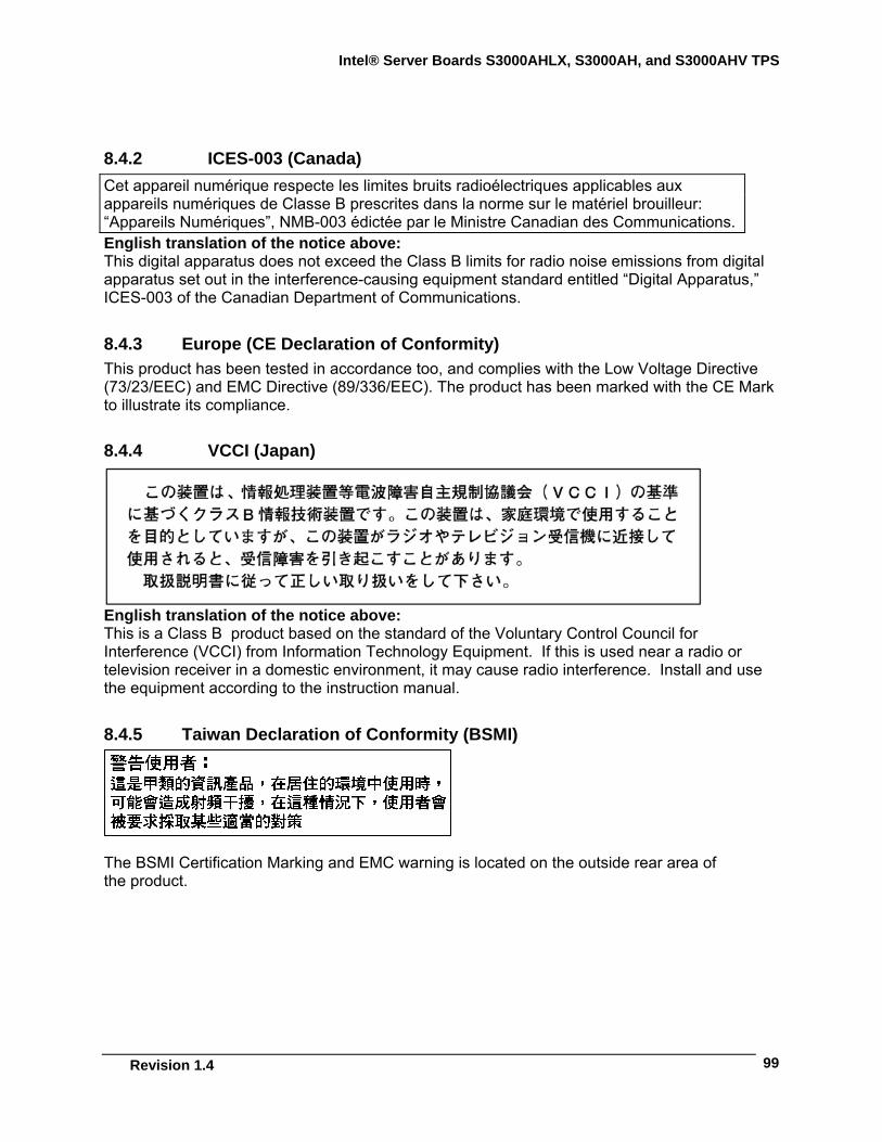
Intel® Server Boards S3000AHLX, S3000AH, and S3000AHV TPS
Revision 1.4
99
8.4.2 ICES-003 (Canada) Cet appareil numérique respecte les limites bruits radioélectriques applicables aux appareils numériques de Classe B prescrites dans la norme sur le matériel brouilleur: “Appareils Numériques”, NMB-003 édictée par le Ministre Canadian des Communications. English translation of the notice above: This digital apparatus does not exceed the Class B limits for radio noise emissions from digital apparatus set out in the interference-causing equipment standard entitled “Digital Apparatus,” ICES-003 of the Canadian Department of Communications.
8.4.3 Europe (CE Declaration of Conformity) This product has been tested in accordance too, and complies with the Low Voltage Directive (73/23/EEC) and EMC Directive (89/336/EEC). The product has been marked with the CE Mark to illustrate its compliance.
8.4.4 VCCI (Japan)
English translation of the notice above: This is a Class B product based on the standard of the Voluntary Control Council for Interference (VCCI) from Information Technology Equipment. If this is used near a radio or television receiver in a domestic environment, it may cause radio interference. Install and use the equipment according to the instruction manual.
8.4.5 Taiwan Declaration of Conformity (BSMI)
The BSMI Certification Marking and EMC warning is located on the outside rear area of the product.
Intel® Server Boards S3000AHLX, S3000AH, and S3000AHV TPS Design and Environmental Specifications
Revision 1.2
100
8.4.6 Korean Compliance (RRL)
English translation of the notice above:
Type of Equipment (Model Name): On License and Product
Certification No.: On RRL certificate. Obtain certificate from local Intel representative
Name of Certification Recipient: Intel Corporation
Date of Manufacturer: Refer to date code on product
Manufacturer/Nation: Intel Corporation/Refer to country of origin marked on product
8.4.7 CNCA (CCC-China) The CCC Certification Marking and EMC warning is located on the outside rear area of the product.
声明 此为 A 级产品,在生活环境中,该产品可能会造成
无线电干扰。在这种情况下,可能需要用户对其干
扰采取可行的措施。
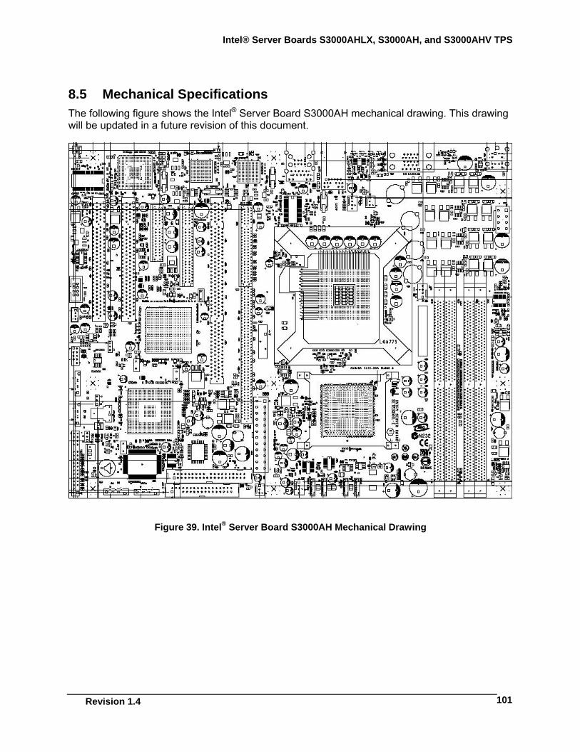
Intel® Server Boards S3000AHLX, S3000AH, and S3000AHV TPS
Revision 1.4
101
8.5 Mechanical Specifications The following figure shows the Intel® Server Board S3000AH mechanical drawing. This drawing will be updated in a future revision of this document.
Figure 39. Intel® Server Board S3000AH Mechanical Drawing
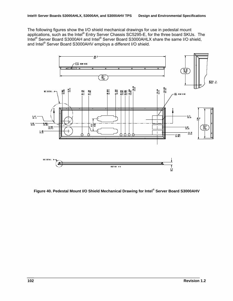
Intel® Server Boards S3000AHLX, S3000AH, and S3000AHV TPS Design and Environmental Specifications
Revision 1.2
102
The following figures show the I/O shield mechanical drawings for use in pedestal mount applications, such as the Intel® Entry Server Chassis SC5295-E, for the three board SKUs. The Intel® Server Board S3000AH and Intel® Server Board S3000AHLX share the same I/O shield, and Intel® Server Board S3000AHV employs a different I/O shield.
Figure 40. Pedestal Mount I/O Shield Mechanical Drawing for Intel® Server Board S3000AHV

Intel® Server Boards S3000AHLX, S3000AH, and S3000AHV TPS
Revision 1.4
103
Figure 41. Pedestal Mount I/O Shield Mechanical Drawing for Intel® Server Boards S3000AH and S3000AHLX
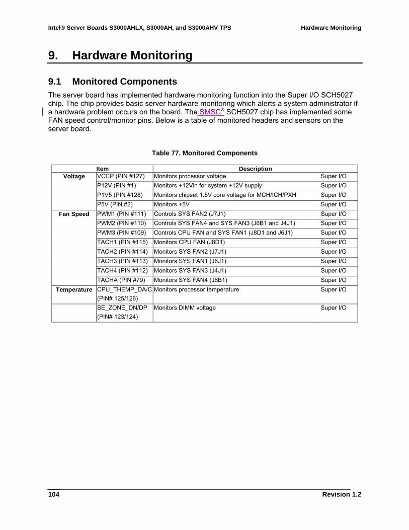
Intel® Server Boards S3000AHLX, S3000AH, and S3000AHV TPS Hardware Monitoring
Revision 1.2
104
9. Hardware Monitoring
9.1 Monitored Components The server board has implemented hardware monitoring function into the Super I/O SCH5027 chip. The chip provides basic server hardware monitoring which alerts a system administrator if a hardware problem occurs on the board. The SMSC® SCH5027 chip has implemented some FAN speed control/monitor pins. Below is a table of monitored headers and sensors on the server board.
Table 77. Monitored Components
Item Description Voltage VCCP (PIN #127) Monitors processor voltage Super I/O
P12V (PIN #1) Monitors +12Vin for system +12V supply Super I/O P1V5 (PIN #128) Monitors chipset 1.5V core voltage for MCH/ICH/PXH Super I/O P5V (PIN #2) Monitors +5V Super I/O
Fan Speed PWM1 (PIN #111) Controls SYS FAN2 (J7J1) Super I/O PWM2 (PIN #110) Controls SYS FAN4 and SYS FAN3 (J6B1 and J4J1) Super I/O PWM3 (PIN #109) Controls CPU FAN and SYS FAN1 (J8D1 and J6J1) Super I/O TACH1 (PIN #115) Monitors CPU FAN (J8D1) Super I/O TACH2 (PIN #114) Monitors SYS FAN2 (J7J1) Super I/O TACH3 (PIN #113) Monitors SYS FAN1 (J6J1) Super I/O TACH4 (PIN #112) Monitors SYS FAN3 (J4J1) Super I/O TACHA (PIN #79) Monitors SYS FAN4 (J6B1) Super I/O Temperature CPU_THEMP_DA/C
(PIN# 125/126) Monitors processor temperature Super I/O
SE_ZONE_DN/DP (PIN# 123/124)
Monitors DIMM voltage Super I/O
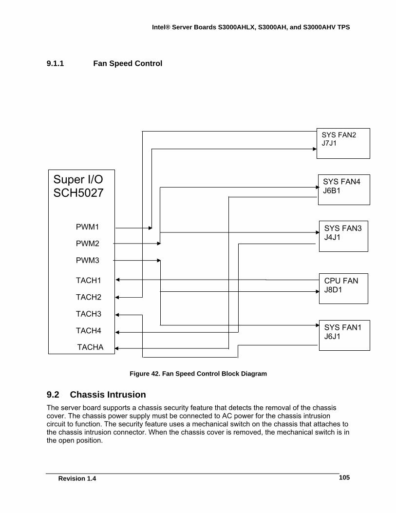
Intel® Server Boards S3000AHLX, S3000AH, and S3000AHV TPS
Revision 1.4
105
9.1.1 Fan Speed Control
Figure 42. Fan Speed Control Block Diagram
9.2 Chassis Intrusion The server board supports a chassis security feature that detects the removal of the chassis cover. The chassis power supply must be connected to AC power for the chassis intrusion circuit to function. The security feature uses a mechanical switch on the chassis that attaches to the chassis intrusion connector. When the chassis cover is removed, the mechanical switch is in the open position.
SYS FAN2 J7J1
SYS FAN4 J6B1
SYS FAN3 J4J1
CPU FAN J8D1
SYS FAN1 J6J1
Super I/O SCH5027
PWM1
PWM2
PWM3
TACH1
TACH2
TACH3
TACH4
TACHA
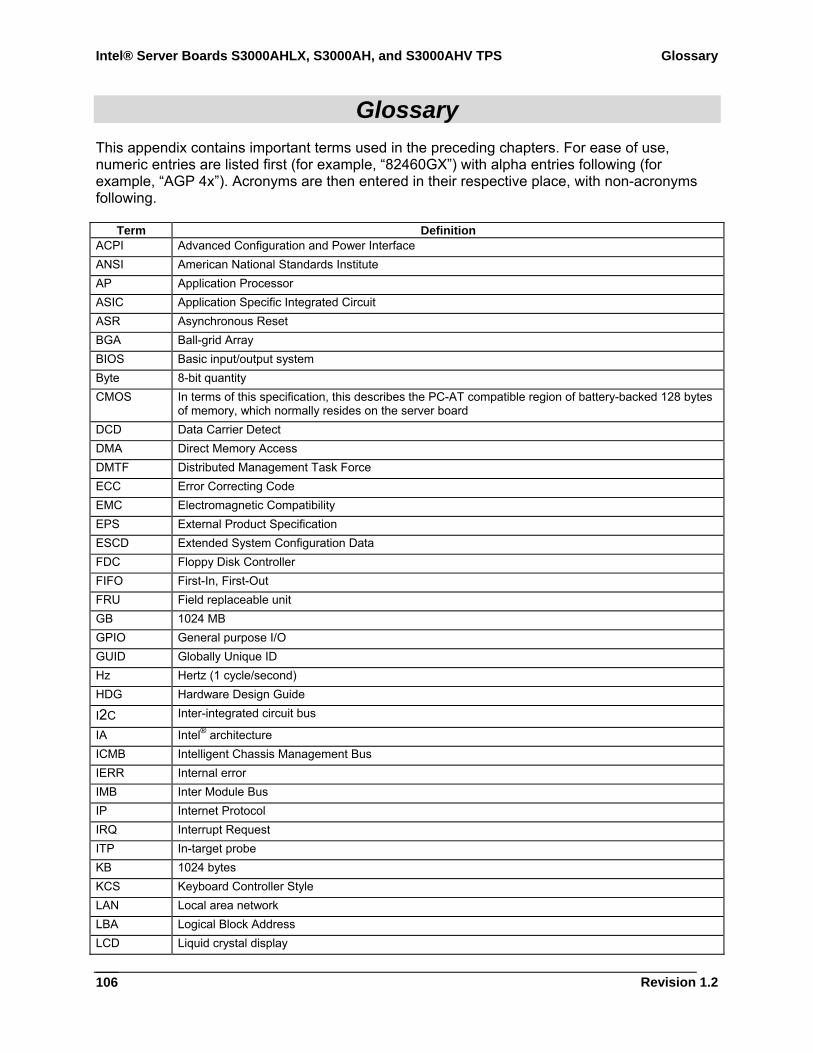
Intel® Server Boards S3000AHLX, S3000AH, and S3000AHV TPS Glossary
Revision 1.2
106
Glossary This appendix contains important terms used in the preceding chapters. For ease of use, numeric entries are listed first (for example, “82460GX”) with alpha entries following (for example, “AGP 4x”). Acronyms are then entered in their respective place, with non-acronyms following.
Term Definition ACPI Advanced Configuration and Power Interface ANSI American National Standards Institute AP Application Processor ASIC Application Specific Integrated Circuit ASR Asynchronous Reset BGA Ball-grid Array BIOS Basic input/output system Byte 8-bit quantity CMOS In terms of this specification, this describes the PC-AT compatible region of battery-backed 128 bytes
of memory, which normally resides on the server board DCD Data Carrier Detect DMA Direct Memory Access DMTF Distributed Management Task Force ECC Error Correcting Code EMC Electromagnetic Compatibility EPS External Product Specification ESCD Extended System Configuration Data FDC Floppy Disk Controller FIFO First-In, First-Out FRU Field replaceable unit GB 1024 MB GPIO General purpose I/O GUID Globally Unique ID Hz Hertz (1 cycle/second) HDG Hardware Design Guide
I2C Inter-integrated circuit bus
IA Intel® architecture ICMB Intelligent Chassis Management Bus IERR Internal error IMB Inter Module Bus IP Internet Protocol IRQ Interrupt Request ITP In-target probe KB 1024 bytes KCS Keyboard Controller Style LAN Local area network LBA Logical Block Address LCD Liquid crystal display
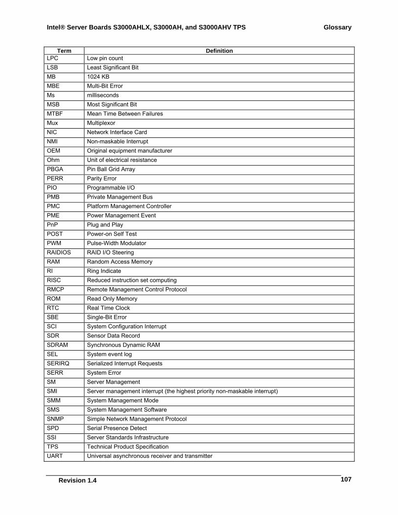
Intel® Server Boards S3000AHLX, S3000AH, and S3000AHV TPS Glossary
Revision 1.4
107
Term Definition LPC Low pin count LSB Least Significant Bit MB 1024 KB MBE Multi-Bit Error Ms milliseconds MSB Most Significant Bit MTBF Mean Time Between Failures Mux Multiplexor NIC Network Interface Card NMI Non-maskable Interrupt OEM Original equipment manufacturer Ohm Unit of electrical resistance PBGA Pin Ball Grid Array PERR Parity Error PIO Programmable I/O PMB Private Management Bus PMC Platform Management Controller PME Power Management Event PnP Plug and Play POST Power-on Self Test PWM Pulse-Width Modulator RAIDIOS RAID I/O Steering RAM Random Access Memory RI Ring Indicate RISC Reduced instruction set computing RMCP Remote Management Control Protocol ROM Read Only Memory RTC Real Time Clock SBE Single-Bit Error SCI System Configuration Interrupt SDR Sensor Data Record SDRAM Synchronous Dynamic RAM SEL System event log SERIRQ Serialized Interrupt Requests SERR System Error SM Server Management SMI Server management interrupt (the highest priority non-maskable interrupt) SMM System Management Mode SMS System Management Software SNMP Simple Network Management Protocol SPD Serial Presence Detect SSI Server Standards Infrastructure TPS Technical Product Specification UART Universal asynchronous receiver and transmitter
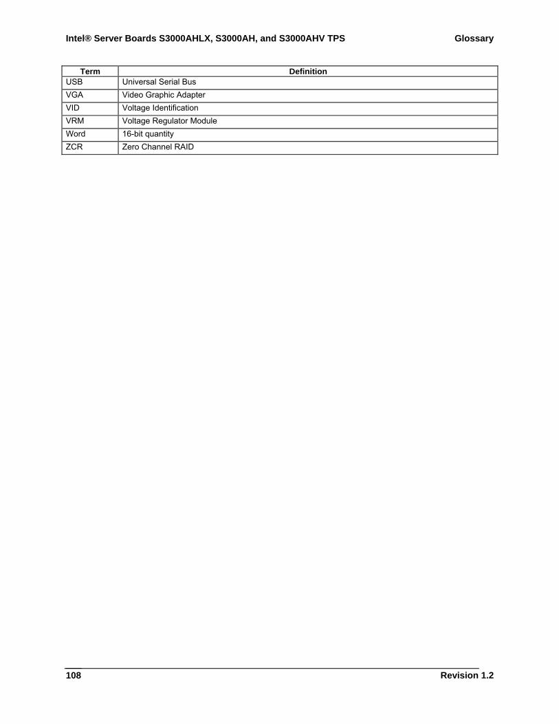
Intel® Server Boards S3000AHLX, S3000AH, and S3000AHV TPS Glossary
Revision 1.2
108
Term Definition USB Universal Serial Bus VGA Video Graphic Adapter VID Voltage Identification VRM Voltage Regulator Module Word 16-bit quantity ZCR Zero Channel RAID
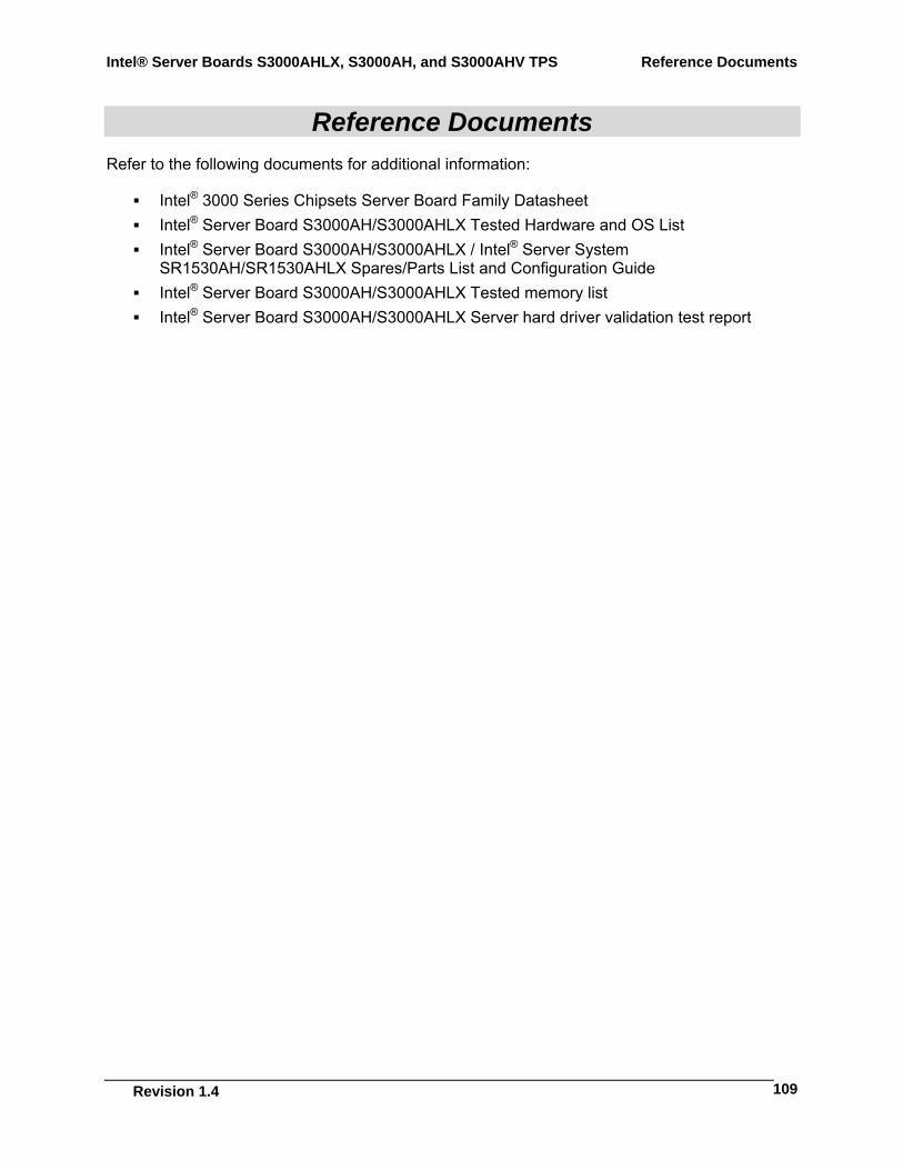
Intel® Server Boards S3000AHLX, S3000AH, and S3000AHV TPS Reference Documents
Revision 1.4
109
Reference Documents Refer to the following documents for additional information:
Intel® 3000 Series Chipsets Server Board Family Datasheet Intel® Server Board S3000AH/S3000AHLX Tested Hardware and OS List Intel® Server Board S3000AH/S3000AHLX / Intel® Server System
SR1530AH/SR1530AHLX Spares/Parts List and Configuration Guide Intel® Server Board S3000AH/S3000AHLX Tested memory list Intel® Server Board S3000AH/S3000AHLX Server hard driver validation test report