integrating sphere user manual - university of arizonachuang/intsphere.pdf · fieldspec®,...
TRANSCRIPT

Integrating Sphere User Manual
ASD.Document 600660 Rev. A
© 2008 by ASD Inc.www.asdi.com

D R A F T
ASD.Document 600660 Rev. A ii Integrating Sphere User Manual
Trademark Information
ASD Inc.
2555 55th Street, Suite 100Boulder, CO 80301 USAPhone: (303) 444-6522www.asdi.com
FieldSpec®, LabSpec®, QualitySpec®, TerraSpec®, AgriSpec®, RxSpec®, ViewSpec™, RS3™, Indico™, and goLab™ are registered, and unregistered trademarks, and the intellectual property of ASD Inc. All trademarks used or displayed in this document are the property of ASD, its affiliates, or third party owners. Unauthorized use of these trademarks is illegal and punishable by law. Nothing contained in this document is to be construed as granting, by implication, estoppel, or otherwise, any license or right of use of any such trademark without the prior and express written permission of ASD, or such third party owner.
This document contains proprietary information protected by copyright law and may not be reproduced in any manner without the express written approval of ASD Inc.
The information and specifications contained in this manual are subject to change without notice. ASD Inc. shall not be held liable for technical, editorial omissions, or errors made herein; nor for incidental or consequential damages resulting from furnishing, performance, or use of this material.
Technical Support
If you have any questions or concerns, please contact ASD Inc. by phone, fax, or email:
Phone: 303-444-6522 X-144Fax: 303-444-6825email: [email protected]: www.asdi.comftp: ftp.asdi.com
Technical support is committed to providing you with a timely response to your questions. We will work with you to provide solutions to your applications. Technical support is available to answer your questions Monday thru Friday, 8 am to 5 pm Mountain Standard Time. We will happily respond to your e-mail queries as well.

ASD.Document 600660 Rev. A iii Integrating Sphere User Manual
Table of Contents
Trademark Information . . . . . . . . . . . . . . . . . . . . . . . . . . . . . . . . . . . . . . . . . . . ii
Technical Support . . . . . . . . . . . . . . . . . . . . . . . . . . . . . . . . . . . . . . . . . . . . . . . ii
Chapter 1 Product Description . . . . . . . . . . . . . . . . . . . . . . . . . . . . . . . . . . . . . . . . . . . . . . 1
Sphere Ports. . . . . . . . . . . . . . . . . . . . . . . . . . . . . . . . . . . . . . . . . . . . . . . . . . 3
Sphere Components. . . . . . . . . . . . . . . . . . . . . . . . . . . . . . . . . . . . . . . . . . . . 5
Theory of Operation . . . . . . . . . . . . . . . . . . . . . . . . . . . . . . . . . . . . . . . . . . . . 6
Stray Light. . . . . . . . . . . . . . . . . . . . . . . . . . . . . . . . . . . . . . . . . . . . . . . . . 7
Reflectance Measurements . . . . . . . . . . . . . . . . . . . . . . . . . . . . . . . . . . . 8
Transmittance Measurements . . . . . . . . . . . . . . . . . . . . . . . . . . . . . . . . 11
Sample Spectra . . . . . . . . . . . . . . . . . . . . . . . . . . . . . . . . . . . . . . . . . . . 12
Chapter 2 Making Measurements . . . . . . . . . . . . . . . . . . . . . . . . . . . . . . . . . . . . . . . . . . . 13
Total Reflection from a Diffuse Surface . . . . . . . . . . . . . . . . . . . . . . . . . . . . 13
Recommended Method . . . . . . . . . . . . . . . . . . . . . . . . . . . . . . . . . . . . . 13
Alternate Recommended Method. . . . . . . . . . . . . . . . . . . . . . . . . . . . . . 14
Method Not Recommended . . . . . . . . . . . . . . . . . . . . . . . . . . . . . . . . . . 15
Reflection from a Specular (mirrorlike) Source. . . . . . . . . . . . . . . . . . . . . . . 16
Transmittance Measurements . . . . . . . . . . . . . . . . . . . . . . . . . . . . . . . . . . . 17
Correcting for Substitution Error . . . . . . . . . . . . . . . . . . . . . . . . . . . . . . . 17
NOT Correcting for Substitution Error. . . . . . . . . . . . . . . . . . . . . . . . . . . 18
Chapter 3 Care and Maintenance . . . . . . . . . . . . . . . . . . . . . . . . . . . . . . . . . . . . . . . . . . . 19
Bulb Replacement and Lamp Alignment . . . . . . . . . . . . . . . . . . . . . . . . . . . 19
Bulb Replacement . . . . . . . . . . . . . . . . . . . . . . . . . . . . . . . . . . . . . . . . . 19
Lamp Alignment . . . . . . . . . . . . . . . . . . . . . . . . . . . . . . . . . . . . . . . . . . . 20
Cleaning the Zenith . . . . . . . . . . . . . . . . . . . . . . . . . . . . . . . . . . . . . . . . . . . 20
Cleaning the Zenith . . . . . . . . . . . . . . . . . . . . . . . . . . . . . . . . . . . . . . . . 21
INDEX . . . . . . . . . . . . . . . . . . . . . . . . . . . . . . . . . . . . . . . . . . . . . . . . . . . . . . . . . 1
ASD.Document 600660 Rev. A iv Integrating Sphere User Manual
Table of Contents

© 2008 ASD Inc. 1 Integrating Sphere User Manual
Chapter 1 Product Description
The Reflectance/Transmittance Integrating Sphere is designed for collecting optical radiation which has been reflected from or transmitted through a sample for the purpose of measuring reflectance or transmittance. The sphere is designed for use with the ASD FieldSpec® spectroradiometer.
The base sphere includes six (6) ports designed to accept supplied sample holders, a light source assembly, fiber adapter, light trap, and port plugs. The assembly is also supplied with two nominal 99% Zenith® reference standards, one calibrated and one uncalibrated.

ASD.Document 600660 Rev. A 2 Integrating Sphere User Manual
www.asdi.com Chapter 1 Product Description
Symbols - Definitions
CAUTION: Risk of danger. This is a personal danger warning. Documentation must be consulted in all cases where this symbol is marked. Failure to acknowledge these warnings could result in personal injury to the user.
CAUTION: Risk of Electric Shock. This is a personal danger warning. Documentation must be consulted in all cases where this symbol is marked. Failure to acknowledge these warnings could result in personal injury to the user.
CAUTION: Hot Surface. This is a personal danger warning. Documentation must be consulted in all cases where this symbol is marked. Failure to acknowledge these warnings could result in personal injury to the user.
Recycle. Items with this symbol indicate that the item should be recycled and not disposed of as general waste.
Warnings and cautions are placed throughout this manual for the convenience of the reader. However, the absence of warnings and cautions do not preclude the use of proper caution and handling. Usual precautions are recommended to be taken at all times, either written or otherwise, to avoid personal injury or damage to ASD equipment.
ASD.Document 600660 Rev. A 3 Integrating Sphere User Manual
www.asdi.com Chapter 1 Product Description
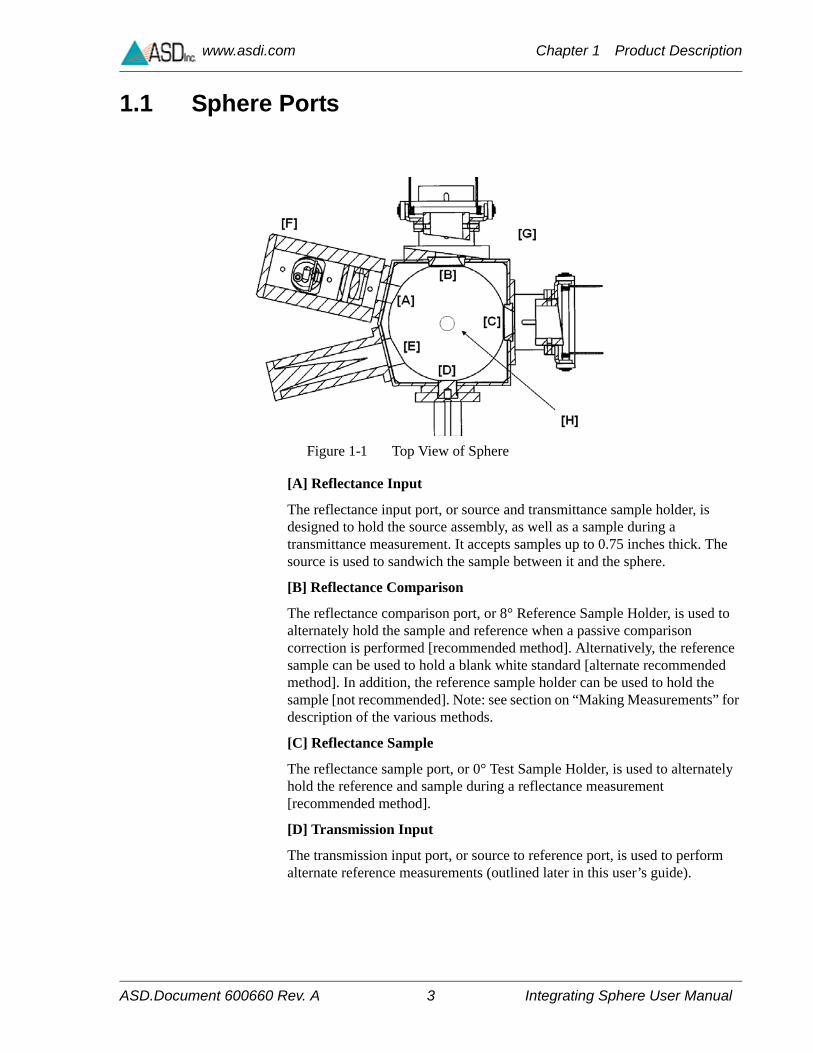
1.1 Sphere Ports
[A] Reflectance Input
The reflectance input port, or source and transmittance sample holder, is designed to hold the source assembly, as well as a sample during a transmittance measurement. It accepts samples up to 0.75 inches thick. The source is used to sandwich the sample between it and the sphere.
[B] Reflectance Comparison
The reflectance comparison port, or 8° Reference Sample Holder, is used to alternately hold the sample and reference when a passive comparison correction is performed [recommended method]. Alternatively, the reference sample can be used to hold a blank white standard [alternate recommended method]. In addition, the reference sample holder can be used to hold the sample [not recommended]. Note: see section on “Making Measurements” for description of the various methods.
[C] Reflectance Sample
The reflectance sample port, or 0° Test Sample Holder, is used to alternately hold the reference and sample during a reflectance measurement [recommended method].
[D] Transmission Input
The transmission input port, or source to reference port, is used to perform alternate reference measurements (outlined later in this user’s guide).
Figure 1-1 Top View of Sphere

ASD.Document 600660 Rev. A 4 Integrating Sphere User Manual
www.asdi.com Chapter 1 Product Description
[E] Specular Exclusion Light Trap
The light trap assembly is used when making diffuse only sample measurements of partly specular samples. The light trap can quickly be converted to a port plug when making total reflectance measurements.
[F] Collimated Light Source Assembly
The light source assembly, provides a collimated beam which illuminates the sample or the Reference Standard. The light source assembly may be removed to change the lamp as necessary.
Note: The collimated light source has a high and low setting; LOW is equivalent to one solar unit while the HIGH setting is greater than one solar unit, which may affect vegetation.
[G] Mounting Boss
Located on the underside of the sphere assembly is a 1/4-20 mounting boss which can be used for an optical bench, tripod, or the supplied mounting rod.
[H] Fiber Adapter Port
The fiber adapter port is located on the top of the sphere. The fiber adapter port is used to mount the fiber of the ASD FieldSpec spectroradiometer using the same type of fitting as is used in the ASD fore optic pistol grip. The fiber is installed by first loosening the fitting and then feeding the fiber optic cable into the fitting. Tighten the fitting finger tight after inserting the fiber optic fully into the fitting.
Figure 1-2 Light Source Power Settings

ASD.Document 600660 Rev. A 5 Integrating Sphere User Manual
www.asdi.com Chapter 1 Product Description
1.2 Sphere Components
Letters in brackets [ ] refer to the top view drawing (Figure 1-1).
1 Collimated Light Source Assembly
2 Light Trap Assembly for port [E]
3 Light Trap Assembly for port [B or C]
4 Fiber Port Adaptor with Strain Relief for port [H]
5 Spare screws and wrenches
6 Cap for Fiber Port Adaptor
7 Black port plugs (interchangeable) for ports [B or C]
8 Transmission Spacer for port [E]
9 White plug for port [E]
10 White plug for port [A]
11 White plug for port [D]
12 Mounting rod for 1/4-20 Boss for [G]
13 Fiber Port Plug for port [H]
Figure 1-3 Sphere Components

ASD.Document 600660 Rev. A 6 Integrating Sphere User Manual
www.asdi.com Chapter 1 Product Description
14 99% Calibrated Reference Standard (white plug)
15 99% Uncalibrated Reference Standard (white plug)
16 Spare Lamps (Qty 2) (not shown in figure 1-2), Osram #64225, 6V, 10W
1.3 Theory of Operation
The integrating sphere collects all the radiation reflected from or transmitted through a sample. The detector responds to a portion of that radiation which, in a well-designed sphere, is a constant portion.
Integrating Sphere Port Configurations
Where:
L - Light source installed in port
W - zenith White reference mounted in port
S - Sample material and Light Trap (3) are mounted in the port when ’S’ is in port B or C
O - port Open (nothing installed) OR Light Trap (3) used
P - port Plugged with zenith plug.
Measured Quantity Port Configuration
[A] [B] [C] [D] [E]
Stray Light Reflectance Mode
Reference (Idr) L O W P P
Sample Measurement (Ids) L W O P P
Sample Reflectance
Reference (Ir) L S W P P
Sample Measurement (Is) L W S P P
Stray Light, Transmission Mode
Reference (Idr) P W O L P
Sample Measurement (Ids) P O W L P
Sample Transmission
Reference (Ir) P W S L P
Sample Measurement (Is) P W O L+S P

ASD.Document 600660 Rev. A 7 Integrating Sphere User Manual
www.asdi.com Chapter 1 Product Description
For specular excluded measurements, the plug in port ’E’ is replaced with Light Trap (2).
The use of the light trap (3) is recommended whenever there is a possibility that ambient light may illuminate the back sides of either ports ’B’ or ’C’ or when either of these ports is open.
The key to making an accurate reflectance or transmission measurement is maintaining an equivalent average sphere interior reflectance for both the sample and reference measurements. These recommended port configurations achieve this goal.
1.3.1 Stray Light
Reflectance and transmission mode stray light should be measured at the start of each measurement session (see Figure 1-4). It is not necessary to measure stray light for each sample. The sphere ports should be configured as listed at “Integrating Sphere Port Configurations” on page 6. We recommend that you collect these spectra in ratio mode – not raw DN or radiance. This will facilitate the use of these spectra for later correction of collected reflectance and/or transmission spectra. Large numbers of scans should be averaged when performing these measurements (200 or more) in order to minimize the introduction of noise during subsequent calculations. An alternative to using these values directly when computing corrected reflectance and transmission, is to use smoothed or curve-fitted versions. For example, the central region (~500-2200 nm) of each stray light curve could be used to compute a best-fit line for approximating stray light. The equations for these lines using the spectra in Figure 1-4 as examples are as follows:
Stray light, reflectance mode = 0.0043 + 1.87e-6 * wavelength
Stray light, transmission mode = -0.0005 + 1.53e-6 * wavelength

ASD.Document 600660 Rev. A 8 Integrating Sphere User Manual
www.asdi.com Chapter 1 Product Description
The alignment of the light source and other sphere components can be verified by monitoring the level of stray light. An increase in stray light is an indication that alignment is necessary (See “Lamp Alignment” on page 18).
1.3.2 Reflectance Measurements
The external integrating sphere means the sample is external to the sphere, and when in place makes up a small part of the sphere wall. In this configuration, the integrating sphere “collects” reflected light from a sample, or transmitted light through a sample, and spreads this energy over the entire surface area of the sphere in a very even distribution. The detector then responds to a portion of the sphere wall energy to derive a meaningful value about the reflectance of the sample.
Figure 1-2 shows the important features of an external integrating sphere. Note: the radiation receptor (in the case of this design, a fiber optic) does not see any part of the sample. Its field of view is occupied by the sphere wall.
Figure 1-4 Stray Light Fraction
500 1000 1500 2000 2500 Wavelength, nm
0.016
0.012
0.008
0.004
0
Reflectance
TransmissionStra
y L
ight
Fra
ctio
n

ASD.Document 600660 Rev. A 9 Integrating Sphere User Manual
www.asdi.com Chapter 1 Product Description
Data collected in Raw DN or radiance mode
Using the properties of an integrating sphere, the reflectance Rs of an unknown sample is a ratio between a known reference and the sample in question as given below:
Where;
Is is the measured sphere output when the sample is illuminated and Ir is the signal measured when the reference material is illuminated and Rr is the calibrated reflectance of the reference.
In practice, this ratio becomes more complex for a couple of reasons:
1 The beam of radiation illuminating the sample or reference is not perfectly collimated. This means that some “stray” radiation is directly getting to the sphere walls without first striking the sample or reference. This background or stray light level may have to be accounted for.
2 The presence of the reference, then of the sample, on the sphere modifies the throughput (the portion of reflected radiation that is seen by the detector). This phenomenon is known as substitution error, and can be corrected for (or ignored if the resulting uncertainty is acceptable).
Figure 1-5 Side view of the sphere.
RsIsIr---- Rr= no stray light correction

ASD.Document 600660 Rev. A 10 Integrating Sphere User Manual
www.asdi.com Chapter 1 Product Description
To account for issue 1 we must measure background radiation within the sphere. To do this, we pass the beam into the sphere and through the sample hole – with no sample in place. That way we measure any stray radiation that the source may contribute to the baseline of the signal. We can then subtract this Id from the former ratio we created (Note: Since Id is usually quite small, it is sometimes ignored. Also, since it behaves exactly as if it were detector “dark current”, it may be able to be corrected in software by taking a “dark scan” in a darkened room, with the light source on, and the sample port open.)
Rs is the value of “Total Reflectance” taken at a 0/d configuration.
NOTE: This ratio holds for samples of a diffuse (or matte) scattering profile – specular samples are discussed later.
Data collected in ratio mode
An alternate (now preferred) method to collecting data in raw DN or radiance mode is to collect all spectra in ratio mode (i.e. run a white reference with the sphere in the reference configuration). The equations are then:
Where:
Rs - corrected sample reflectance
R’s - measured sample reflectance
Rr - reference sample reflectance
Rd - stray light (measured in reflectance mode)
Rs Is Id– RrIr Id–
-------------------------------= with stray light correction
Rs R's Rr= no stray light correction
Rs R's Rd– Rr1 Rd–
------------------------------------= with stray light correction
ASD.Document 600660 Rev. A 11 Integrating Sphere User Manual
www.asdi.com Chapter 1 Product Description
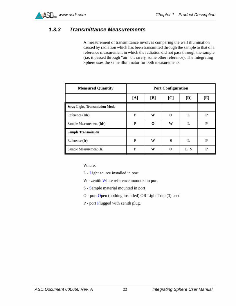
1.3.3 Transmittance Measurements
A measurement of transmittance involves comparing the wall illumination caused by radiation which has been transmitted through the sample to that of a reference measurement in which the radiation did not pass through the sample (i.e. it passed through “air” or, rarely, some other reference). The Integrating Sphere uses the same illuminator for both measurements.
Where:
L - Light source installed in port
W - zenith White reference mounted in port
S - Sample material mounted in port
O - port Open (nothing installed) OR Light Trap (3) used
P - port Plugged with zenith plug.
Measured Quantity Port Configuration
[A] [B] [C] [D] [E]
Stray Light, Transmission Mode
Reference (Idr) P W O L P
Sample Measurement (Ids) P O W L P
Sample Transmission
Reference (Ir) P W S L P
Sample Measurement (Is) P W O L+S P

ASD.Document 600660 Rev. A 12 Integrating Sphere User Manual
www.asdi.com Chapter 1 Product Description
1.3.4 Sample Spectra
Spectra were collected in reflectance mode using the port configurations listed in “Integrating Sphere Port Configurations” on page 6. While the errors associated with stray light are small, stray light corrections were applied prior to plotting the data.
Figure 1-6 Leaf Spectra
500 1000 1500 2000 2500 Wavelength, nm
0.8
0.6
0.4
0.2
0
Reflectance
1-Transmission
Ref
lect
ance
, 1-T
rans
mis
sion

© 2007 ASD Inc. 13 QualitySpec® BT User Manual
Chapter 2 Making Measurements
2.1 Total Reflection from a Diffuse Surface
2.1.1 Recommended Method
This recommended method corrects for substitution error.
* The sample can be replaced with a piece which has nearly the same reflectance as the sample (within 20% is close enough). This will correct for substitution error with only one reference scan for use with several similar samples.
The use of the light trap (3) is recommended whenever there is a possibility that ambient light may illuminate the back sides of either ports ’B’ or ’C’ or when either of these ports is open.
Reflectance Reference Reflectance Sample Dark Reading
Quantity Measured ==> Ir Is Id
Port
Reflectance Input [A] Collimated Light Source Assembly
Collimated Light Source Assembly
Collimated Light Source Assembly
Reflectance Comparison [B] Sample* + Light Trap (3) (opt.) Reference Standard Reference Standard
Reflectance Sample [C] Reference Standard Sample + Light Trap (3) (opt.)
Open Port in a Dark room or Light Trap (3) (opt.)
Transmission Input [D] White Plug White Plug White Plug
Light Trap [E] White Plug White Plug White Plug
ASD.Document 600549 Rev. A 14 QualitySpec® BT User Manual
www.asdi.com Chapter 2 Making Measurements
where;
Rr is the reflectance of the calibrated reference standard
If Id is found to be negligible, it can be ignored.
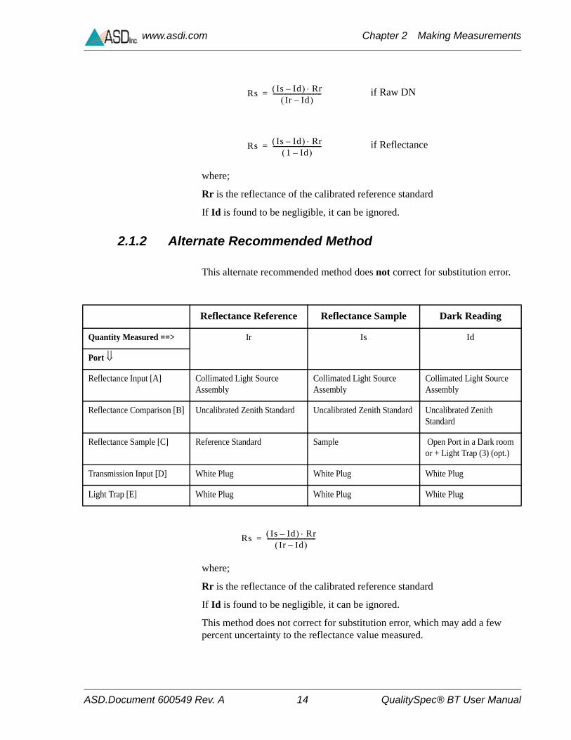
2.1.2 Alternate Recommended Method
This alternate recommended method does not correct for substitution error.
where;
Rr is the reflectance of the calibrated reference standard
If Id is found to be negligible, it can be ignored.
This method does not correct for substitution error, which may add a few percent uncertainty to the reflectance value measured.
Rs Is Id– RrIr Id–
-------------------------------= if Raw DN
Rs Is Id– Rr1 Id–
-------------------------------= if Reflectance
Reflectance Reference Reflectance Sample Dark Reading
Quantity Measured ==> Ir Is Id
Port
Reflectance Input [A] Collimated Light Source Assembly
Collimated Light Source Assembly
Collimated Light Source Assembly
Reflectance Comparison [B] Uncalibrated Zenith Standard Uncalibrated Zenith Standard Uncalibrated Zenith Standard
Reflectance Sample [C] Reference Standard Sample Open Port in a Dark room or + Light Trap (3) (opt.)
Transmission Input [D] White Plug White Plug White Plug
Light Trap [E] White Plug White Plug White Plug
Rs Is Id– RrIr Id–
-------------------------------=

ASD.Document 600549 Rev. A 15 QualitySpec® BT User Manual
www.asdi.com Chapter 2 Making Measurements
2.1.3 Method Not Recommended
This method is not recommended because it corrects for substitution error, but potentially adds an error which is much greater than the substitution error.
where;
Rr is the reflectance of the calibrated reference standard.
If Ids and Idr are found to be negligible, they can be ignored.
Reflectance Reference
Reflectance Sample Dark Reading Dark Reading
Quantity Measured ==> Ir Is Idr Ids
Port
Reflectance Input [A] White Plug Collimated Light Source Assembly
White Plug Collimated Light Source Assembly
Reflectance Comparison [B]
Reflectance Standard Reflectance Standard Open Port in a Dark room or Light Trap (3) (opt.)
Reflectance Standard
Reflectance Sample [C] Sample Sample Sample Open Port in a Dark room or Light Trap (3) (opt.)
Transmission Input [D] Collimated Light Source Assembly
White Plug Collimated Light Source Assembly
White Plug
Light Trap [E] White Plug White Plug White Plug White Plug
Rs Is Ids– RrIr Idr–
----------------------------------=

ASD.Document 600549 Rev. A 16 QualitySpec® BT User Manual
www.asdi.com Chapter 2 Making Measurements
2.2 Reflection from a Specular (mirrorlike) Source
The methods described above for measuring the reflectance of diffuse materials are also valid for measuring the reflectance of specular materials, with a couple of additions.
• It is always advisable to use a reference which has nearly the same geometrical scattering properties as the sample. Therefore, to measure the reflectance of a specular sample, a calibrated first-surface mirror should be used as the reference. If the sample is neither very diffuse nor very specular, it is necessary to choose a reference that comes close to the sample’s geometrical scattering properties. In extreme cases, a reference can be made that matches the sample’s geometry, and calibrated on a reference instrument.
• In some cases, it is desirable to measure only the diffuse portion of the scattered light from a sample that is a combination of specular and diffuse. In these cases, the white plug should be removed from the light trap [E]. This will reject most of the purely specular component of reflected light. It should be noted that it is impossible to reject the entire purely specular component without rejecting some of the near-specular component also. This means the results of specular-rejected measurements are instrument-specific. Different results should be expected from instruments with different sphere geometries and/or different light source optics.

ASD.Document 600549 Rev. A 17 QualitySpec® BT User Manual
www.asdi.com Chapter 2 Making Measurements
2.3 Transmittance Measurements
2.3.1 Correcting for Substitution Error
If Id is found to be negligible, it can be ignored.
Reflectance Reference Transmittance Sample Dark Reading
Quantity Measured ==> Ir Is Id
Port
Reflectance Input [A] White Plug White Plug White Plug
Reflectance Comparison [B] Uncalibrated Zenith Standard Uncalibrated Zenith Standard Open Port in a Dark room or Light Trap (3) (opt.)
Reflectance Sample [C] Sample Open Port in a Dark room or Light Trap (3) (opt.)
Uncalibrated Zenith Standard
Transmission Input [D] Collimated Light Source Assembly
Collimated Light Source Assembly and Sample
Collimated Light Source Assembly
Light Trap [E] White Plug White Plug White Plug
T Is Id– RrIr Id–
-------------------------------= if Raw DN
T Is Id– Rr1 Id–
-------------------------------= if Reflectance

ASD.Document 600549 Rev. A 18 QualitySpec® BT User Manual
www.asdi.com Chapter 2 Making Measurements
2.3.2 NOT Correcting for Substitution Error
If Id is found to be negligible, it can be ignored.
Reflectance Reference Transmittance Sample Dark Reading
Quantity Measured ==> Ir Is Id
Port
Reflectance Input [A] White Plug White Plug White Plug
Reflectance Comparison [B] Uncalibrated Zenith Standard Uncalibrated Zenith Standard Open Port in a Dark room or Light Trap (3) (opt.)
Reflectance Sample [C] Open Port in a Dark room or Light Trap (3) (opt.)
Open Port in a Dark room or Light Trap (3) (opt.)
Uncalibrated Zenith Standard
Transmission Input [D] Collimated Light Source Assembly
Collimated Light Source Assembly and Sample
Collimated Light Source Assembly
Light Trap [E] White Plug White Plug White Plug
T Is Id– RrIr Id–
-------------------------------=

© 2008 ASD Inc. 19 Integrating Sphere User Manual
Chapter 3 Care and Maintenance
3.1 Bulb Replacement and Lamp Alignment
3.1.1 Bulb Replacement
Step 1 Remove the lamp assembly from the projector housing by removing the two vertical screws as shown in Figure 3-1 on page 19. Note that the lamp sits behind a small hole in a baffle-plate.
Step 2 Replace the lamp and reinstall the lamp assembly.
Step 3 Place the projector housing back onto the sphere.
Figure 3-1 Lamp Assembly

ASD.Document 600660 Rev. A 20 Integrating Sphere User Manual
www.asdi.com Chapter 3 Care and Maintenance
3.1.2 Lamp Alignment
Step 1 Set the current to a low level, enough to see reddish light projected from the lamp assembly, but not enough to make the assembly too hot to handle comfortably.
Step 2 Loosen the two horizontal screws and the two vertical screws slightly. Maneuver the lamp assembly until the collimated beam clears the sample port cleanly and, when a high-quality first-surface mirror is placed in the sample port, the beam also clears the light trap port cleanly.
Step 3 Tighten the screws.
3.2 Cleaning the Zenith
Sphere Interior
The interior of the RTS-3Z is machined of Zenith diffuse polymer material. The sphere should be handled carefully at all times to protect its interior surface. The material should be treated as first surface primary optic and should not come into contact with any substance including human fingers. When the sphere is not in use, it should be covered and stored in a relatively dust-free area to prevent contamination of the Zenith optical coating.
Figure 3-2 Lamp Assembly
ASD.Document 600660 Rev. A 21 Integrating Sphere User Manual
www.asdi.com Chapter 3 Care and Maintenance
The Zenith, a solid, machined form of PTFE, is highly reflective (>95%) and Lambertian over the broad spectral range of 250-2500nm. It is a hydrophobic material (repels water), but is very sensitive to contamination from organic substances (oils, soaps, solvents, etc.). The material should always be handled with latex gloves or other contaminant free barriers (finger cots, nylon gloves, sterile plastic bags). Tissues and other paper products should not be used to contact the material as they may leave behind residual particles that can alter the optical properties of the material.
The only liquids that may safely contact the material are distilled water and optical grade alcohol. Alcohol will rapidly absorb into the material (and pass through it) but may be removed completely by allowing the liquid to “dry” or evaporate from the material. This drying can be accelerated by baking at 90ºC for 24 to 48 hours.
The material is an excellent thermal insulator and is also an excellent electrical insulator which may develop a static charge that can attract dust.
3.2.1 Cleaning the Zenith
Dust and Surface Contamination
The Zenith may develop a surface dust contamination over time due to a static charge or the material being stored in an unprotected state. Dry nitrogen or clean air can be used to blow off most of this dust. DO NOT use Canned Air, as most of these products contain a hydrocarbon based propellant which can contaminate the material.
Additionally, for difficult dust contamination problems, the material may be rinsed with distilled water after removing the material from its housing. If the material is rinsed, allow several hours for the material to dry before attempting use. Again, this drying can be accelerated by baking at 90ºC for 24 to 48 hours. If the material continues to exhibit contamination, contact the manufacturer for additional recommendations.

ASD.Document 600660 Rev. A 22 Integrating Sphere User Manual
www.asdi.com Chapter 3 Care and Maintenance
Notes:

ASD.Document 600660 Rev. A 23 Integrating Sphere User Manual
Index
A
alignment 8
B
Bulb Replacement 19
C
Cleaning the Zenith 21
D
Data collected in ratio mode 10Data collected in Raw DN or radiance mode 9
I
Id 10Integrating Sphere Port Configurations 6Ir 9Is 9
L
Lamp Alignment 20
M
mounting boss 4
R
Reflectance Measurements 8Reflection from a Specular (mirrorlike) Source 16Rs 9
S
Sample Spectra 12Sphere Components 5Stray Light 7support iiSymbols 2
T
technical support iiTheory of Operation 6trademarks iiTransmittance Measurements 11, 17
Z
Zenith 20