integrating data with external applications · planning to process data for integration . . . 107...
TRANSCRIPT
IBM Maximo Asset ManagementVersion 7 Release 6
Integrating Data With ExternalApplications
���

NoteBefore using this information and the product it supports, read the information in “Notices” on page 383.
This edition applies to version 7, release 5, modification 0 of IBM Maximo Integration Framework and to allsubsequent releases and modifications until otherwise indicated in new editions.
© Copyright IBM Corporation 2008, 2014.US Government Users Restricted Rights – Use, duplication or disclosure restricted by GSA ADP Schedule Contractwith IBM Corp.
Contents
Integrating data with externalapplications . . . . . . . . . . . . . 1Integration framework overview. . . . . . . . 1
Architecture . . . . . . . . . . . . . 2Framework for data exchange . . . . . . 2Framework for operational managementproduct integration . . . . . . . . . . 4Framework for user interface integration . . . 4
Enabling data export and import . . . . . . . 5Preparing the system . . . . . . . . . . 5
Configuring JMS queues . . . . . . . . 5Configuring integration properties . . . . . 5Activating the cron task for JMS queues . . . 5Exporting data to a test file . . . . . . . 6Importing data from a test file . . . . . . 6
Integration components. . . . . . . . . . . 7Object structures . . . . . . . . . . . . 7
Object identification . . . . . . . . . . 7Alternate keys . . . . . . . . . . . . 8Object fields . . . . . . . . . . . . 8Interface table and flat file considerations. . . 9Modification of a predefined object structure . 9Configuring an object structure . . . . . . 10
Channels and services . . . . . . . . . . 14Publish channels. . . . . . . . . . . 14Invocation channels . . . . . . . . . 15Object structure services . . . . . . . . 18Enterprise services . . . . . . . . . . 18Standard services . . . . . . . . . . 22
Endpoints and handlers . . . . . . . . . 22Configuring an endpoint . . . . . . . . 23Predefined endpoint handlers . . . . . . 25
Integration web services . . . . . . . . . 38Web service sources . . . . . . . . . 38Web service deployment options . . . . . 39Web service deployment actions . . . . . 40Schema generation . . . . . . . . . . 40Generation of a Web Services DescriptionLanguage file . . . . . . . . . . . . 41UDDI registration . . . . . . . . . . 41Creating and deploying web services . . . . 42Web service interactions overview . . . . . 44
External systems. . . . . . . . . . . . 45Configuring an external system. . . . . . 46
Predefined integration content . . . . . . . 59Master data objects . . . . . . . . . . 59Item and inventory objects . . . . . . . 68Documents objects . . . . . . . . . . 74Transaction interface objects . . . . . . . 83System objects . . . . . . . . . . . 93Data loading order . . . . . . . . . 106
Integration data processing . . . . . . . . . 107Planning to process data for integration . . . 107Inbound data processing . . . . . . . . 108
Asynchronous processing of inboundmessages . . . . . . . . . . . . . 108Synchronous processing of inbound messages 109Initiation of asynchronous processing ofinbound data . . . . . . . . . . . 109Initiation of synchronous processing ofinbound data . . . . . . . . . . . 111Processing sequences . . . . . . . . . 112
Outbound data processing . . . . . . . . 115Asynchronous integration with a publishchannel . . . . . . . . . . . . . 115Synchronous integration with an invocationchannel . . . . . . . . . . . . . 117
Configuring integration processing . . . . . 118Configuring asynchronous processing ofinbound messages by using enterpriseservices . . . . . . . . . . . . . 118Configuring asynchronous processing ofoutbound messages by using publishchannels . . . . . . . . . . . . . 119
Rule-based customization . . . . . . . . 120Rule definitions for objects and records. . . 120Processing rule definitions . . . . . . . 121Conditions and evaluations. . . . . . . 124Integration controls . . . . . . . . . 128Configuring processing rules . . . . . . 131
Code-based customization . . . . . . . . 144Customization Java classes and methods . . 144Customization with automation scripts . . . 151XSL mapping . . . . . . . . . . . 167Interface table user exit class . . . . . . 168
Configuring the integration framework . . . . . 169Integration system properties . . . . . . . 169JMS queue configuration . . . . . . . . 175
Creating and configuring a queue . . . . 176Sequential queues . . . . . . . . . . 177Continuous queues . . . . . . . . . 178Queue message format . . . . . . . . 182Queue selectors . . . . . . . . . . 184Viewing and deleting messages in a JMSqueue . . . . . . . . . . . . . . 185Configuring queues with WebSphere MQ . . 186
Error management . . . . . . . . . . 187Non-queue error management . . . . . . 187Queue-based error management . . . . . 187Configuring error management . . . . . 188Error notification . . . . . . . . . . 188Message reprocessing. . . . . . . . . 189Error management with file-based dataimport. . . . . . . . . . . . . . 192Interface table error management. . . . . 195Common causes of errors . . . . . . . 196Error research . . . . . . . . . . . 197Message tracking . . . . . . . . . . 198
Cluster configuration . . . . . . . . . . 202JMS queues in a server cluster. . . . . . 202
© Copyright IBM Corp. 2008, 2014 iii
Configuring the cron task . . . . . . . 205Configuring a message processing server . . 206Global directory configuration . . . . . . 206Access to services by inbound messages . . 206
Integration security . . . . . . . . . . 207Authentication security . . . . . . . . 207Authorization security . . . . . . . . 214
Language support . . . . . . . . . . . 216Default processing of multiple languages . . 216Multilanguage attributes. . . . . . . . 216Bidirectional language support . . . . . 217Bidirectional language formats . . . . . 217Configuring bidirectional language supportfor external systems . . . . . . . . . 218
Exporting and importing file-based data . . . . 218Exporting and importing data in the ExternalSystems application . . . . . . . . . . 218
Exporting file-based data . . . . . . . 218Importing file-based data . . . . . . . 219
Cron tasks for processing inbound data . . . 220XMLFILECONSUMER cron task . . . . . 221FLATFILECONSUMER cron task . . . . . 221
Configuring an application for data export andimport. . . . . . . . . . . . . . . 223
Defining the object structure content . . . 223Enabling data import and export in anapplication . . . . . . . . . . . . 224Initiating data export and import in anapplication . . . . . . . . . . . . 224
REST API . . . . . . . . . . . . . . 226REST API framework. . . . . . . . . . 226Supported representations . . . . . . . . 227Resource handlers and URIs . . . . . . . 228GET method. . . . . . . . . . . . . 228
Query parameters and operators . . . . . 231_opmodeor parameter . . . . . . . . 233_rsStart and _maxItems parameters . . . . 233_orderbyasc parameter . . . . . . . . 234_includecols and _excludecols parameters 235_dropnulls parameter. . . . . . . . . 236_format and _compact parameters . . . . 237Content negotiation of representations . . . 238In-session scrolling . . . . . . . . . 239Caching of GET requests . . . . . . . 239
PUT, POST, and DELETE methods . . . . . 241PUT method . . . . . . . . . . . 241POST method . . . . . . . . . . . 242DELETE method . . . . . . . . . . 243Concurrent updates of resources . . . . . 243
Service method queries and updates. . . . . 244Service methods that use HTTP POST toupdate resources . . . . . . . . . . 244Service methods that use HTTP GET toquery resources. . . . . . . . . . . 245Service methods that use HTTP GET toquery system data . . . . . . . . . . 247
HTTP header properties . . . . . . . . . 247Response codes. . . . . . . . . . . . 249Security in the REST API . . . . . . . . 249Customization of the REST API . . . . . . 251REST query parameters . . . . . . . . . 252
REST system properties . . . . . . . . . 256External service calls . . . . . . . . . . 259
OSLC integration . . . . . . . . . . . . 259OSLC implementation in Maximo AssetManagement . . . . . . . . . . . . 259OSLC configuration . . . . . . . . . . 261
Specification of OSLC resources . . . . . 261Domain service providers . . . . . . . 262Saved queries . . . . . . . . . . . 264OSLC security . . . . . . . . . . . 265OSLC logging . . . . . . . . . . . 266
HTTP transactions. . . . . . . . . . . 267OSLC resource queries . . . . . . . . 267Creation of a resource instance . . . . . 272Modification of resources . . . . . . . 272HTTP headers . . . . . . . . . . . 275HTTP response codes. . . . . . . . . 277
Integrating as an OSLC consumer . . . . . 278Creation of OSLC provider records . . . . 278Designing an OSLC interaction . . . . . 283Creating interaction groups. . . . . . . 290Example: Running an OSLC interaction . . 291Public URI changes . . . . . . . . . 293Migration of OSLC integrations . . . . . 293Manual UI modification . . . . . . . . 294OSLC properties . . . . . . . . . . 295
Integration queries . . . . . . . . . . . 295Query services . . . . . . . . . . . . 296Creating an enterprise service query. . . . . 296Web service queries . . . . . . . . . . 296Query XML structure . . . . . . . . . . 297Query selection criteria . . . . . . . . . 300
Field selection . . . . . . . . . . . 300Field evaluation . . . . . . . . . . 302Range selection. . . . . . . . . . . 302Where clause selection . . . . . . . . 303
Interface tables . . . . . . . . . . . . . 305Creation of interface tables . . . . . . . . 306Regeneration of interface tables . . . . . . 307Deletion of interface tables and records. . . . 307Format of interface tables . . . . . . . . 307Interface table polling . . . . . . . . . 311
Interface table polling cron task . . . . . 311Advanced interface table polling . . . . . 312
Processing interface tables on an external system 313Enabling inbound processing . . . . . . 313Enabling outbound processing. . . . . . 313
Integration modules . . . . . . . . . . . 314Integration module components . . . . . . 314
Integration module definitions. . . . . . 314Operational management products . . . . 315Logical management operations . . . . . 315
Implementation prerequisites . . . . . . . 316Implementation properties . . . . . . . . 317
Integration module parameters . . . . . 317Integration module process flow . . . . . 318Endpoints . . . . . . . . . . . . 318
Invocation channel or Java class implementation 319Invocation channel and Java classcomparison . . . . . . . . . . . . 319Invocation channel implementation . . . . 321
iv Integrating Data With External Applications
Java class implementation . . . . . . . 322Integration module processing. . . . . . . 323
Identification of integration components . . 323Integration module invocation. . . . . . 324Integration module response processing . . 327
Configuring integration modules . . . . . . 327Creating integration modules . . . . . . 327Selecting logical management operations forintegration modules . . . . . . . . . 328Associating a logical management operationwith an integration module. . . . . . . 329
Configuring logical management operations . . 331Creating logical management operations . . 331Adding attributes to logical managementoperations . . . . . . . . . . . . 332
Launch in Context feature . . . . . . . . . 332Preparation of the external application . . . . 333Launch entry URL into an external application 333Launch entry URL into a product application 333Enabling launch-in-context . . . . . . . . 334
Creating a launch entry . . . . . . . . 334
Configuring a signature option for a launchpoint . . . . . . . . . . . . . . 336Adding a launch point to an applicationmenu . . . . . . . . . . . . . . 336Adding a button as a launch point . . . . 337Adding a condition to a launch point . . . 337
Integration reference information . . . . . . . 338Integration system properties . . . . . . . 338Integration XML . . . . . . . . . . . 344
Overview. . . . . . . . . . . . . 344XML structure . . . . . . . . . . . 346Integration XML schemas . . . . . . . 356
Collaboration switches . . . . . . . . . 368Format of collaboration switches . . . . . 368Retrieving a collaboration switch . . . . . 369Configuring collaboration switches . . . . 370Predefined collaboration switches . . . . 372
Notices . . . . . . . . . . . . . . 383Trademarks . . . . . . . . . . . . . . 384
Contents v

vi Integrating Data With External Applications
Integrating data with external applications
The integration framework helps you to integrate application data with otherapplications, either within your enterprise or with external systems. Theframework includes predefined content that enables integration with a number ofbusiness objects, and a tool kit that you can use to extend predefined integrationcontent and to develop new integration points.
Integration framework overviewThe integration framework helps you to integrate application data with otherapplications, either within your enterprise or with external systems. Theframework includes predefined content that enables integration with a number ofbusiness objects, and a tool kit that you can use to extend predefined integrationcontent and to develop new integration points.
The integration framework includes the following components and features:v Predefined integration contentv Applications to create and configure integration componentsv Support for multiple communication modes including web services, hyper text
transfer protocol (HTTP), and Java Message Service (JMS) messagingv Support for different data formats, including database interface tables, XML and
JavaScript Object Notation (JSON) messages, and flat files such ascomma-separated text files
v Event-based, batch, program-initiated, and user-initiated processing andcontext-based launch of external applications
v Support for integration to operational management products (OMPs)v Support for clustered environmentsv Support for interacting with applications that support the Open Services for
Lifecycle Collaboration (OSLC) integration specification. The integrationframework can enable an application to be an OSLC consumer application thatcan integrate with an external application that has implemented OSLC providercapabilities.
The integration framework provides multiple options for sending and receivingdata. Evaluate which approach is the most efficient for your requirements whenyou are planning an integration. Some typical integration scenarios include:v Load files with legacy data during an implementation.v Synchronize master data between a product application and an external ERP
application.v Use web services to enable real-time querying of product application data by an
external application.v Call an external application to validate data that is entered in a product
application.
If you want to import a large number of records from an external system, importthe data in batch files or use interface tables. This approach separates the data sothat multiple messages are processed as separate transactions. With a singletransaction that processes synchronously, such as a web service call, limit thenumber of messages in a single transaction to ensure that the transaction processes
© Copyright IBM Corp. 2008, 2014 1
in an acceptable length of time. When you are planning an integration, evaluatewhich integration option is most appropriate for your requirements.
Predefined integration content includes support for a number of business objectsand insert, update, and delete functions on these business objects is enabled. Whenyou use predefined content, there are certain limitations that can affect yourimplementation. If business rules exist within the business object that do not allowa function, for example the delete function, the function is not available forintegration. In addition to support for insert, update and delete operations, theproduct applications support other functions that are available as actions.Predefined integration content does not support all the actions that are available.In most cases, the Change Status action is supported through integration.Related concepts:“Predefined integration content” on page 59The integration framework provides predefined integration content, includingobject structures, publish channels and enterprise services that support importingdata from external system or exporting data to them.
ArchitectureThe integration framework architecture includes the data, transport,communication, and security components required to exchange informationbetween separate applications and systems.
Framework for data exchangeThe framework for data exchange includes components and tools that you can useto implement different types of integration scenarios.
Components
The framework includes predefined integration components and applications youcan use to configure components. The main components are described in thefollowing table.
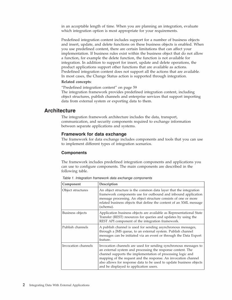
Table 1. Integration framework data exchange components
Component Description
Object structures An object structure is the common data layer that the integrationframework components use for outbound and inbound applicationmessage processing. An object structure consists of one or morerelated business objects that define the content of an XML message(schema).
Business objects Application business objects are available as Representational StateTransfer (REST) resources for queries and updates by using theREST API component of the integration framework.
Publish channels A publish channel is used for sending asynchronous messages,through a JMS queue, to an external system. Publish channelmessages can be initiated via an event or through the Data Exportfeature.
Invocation channels Invocation channels are used for sending synchronous messages toan external system and processing the response content. Thechannel supports the implementation of processing logic andmapping of the request and the response. An invocation channelalso allows for response data to be used to update business objectsand be displayed to application users.
2 Integrating Data With External Applications
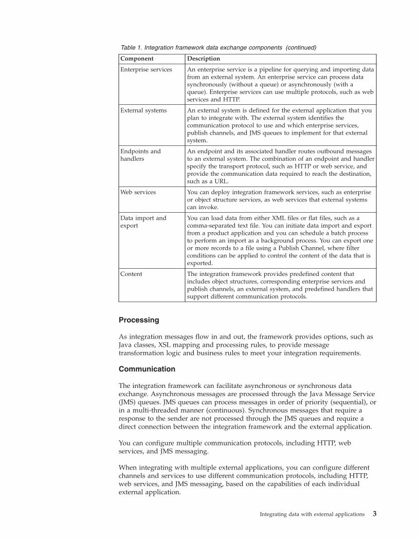
Table 1. Integration framework data exchange components (continued)
Component Description
Enterprise services An enterprise service is a pipeline for querying and importing datafrom an external system. An enterprise service can process datasynchronously (without a queue) or asynchronously (with aqueue). Enterprise services can use multiple protocols, such as webservices and HTTP.
External systems An external system is defined for the external application that youplan to integrate with. The external system identifies thecommunication protocol to use and which enterprise services,publish channels, and JMS queues to implement for that externalsystem.
Endpoints andhandlers
An endpoint and its associated handler routes outbound messagesto an external system. The combination of an endpoint and handlerspecify the transport protocol, such as HTTP or web service, andprovide the communication data required to reach the destination,such as a URL.
Web services You can deploy integration framework services, such as enterpriseor object structure services, as web services that external systemscan invoke.
Data import andexport
You can load data from either XML files or flat files, such as acomma-separated text file. You can initiate data import and exportfrom a product application and you can schedule a batch processto perform an import as a background process. You can export oneor more records to a file using a Publish Channel, where filterconditions can be applied to control the content of the data that isexported.
Content The integration framework provides predefined content thatincludes object structures, corresponding enterprise services andpublish channels, an external system, and predefined handlers thatsupport different communication protocols.
Processing
As integration messages flow in and out, the framework provides options, such asJava classes, XSL mapping and processing rules, to provide messagetransformation logic and business rules to meet your integration requirements.
Communication
The integration framework can facilitate asynchronous or synchronous dataexchange. Asynchronous messages are processed through the Java Message Service(JMS) queues. JMS queues can process messages in order of priority (sequential), orin a multi-threaded manner (continuous). Synchronous messages that require aresponse to the sender are not processed through the JMS queues and require adirect connection between the integration framework and the external application.
You can configure multiple communication protocols, including HTTP, webservices, and JMS messaging.
When integrating with multiple external applications, you can configure differentchannels and services to use different communication protocols, including HTTP,web services, and JMS messaging, based on the capabilities of each individualexternal application.
Integrating data with external applications 3
Security
The integration framework uses the product support for J2EE authenticationsecurity so that you can configure for Enterprise Java Beans (EJBs), HTTP, and webservices. You can configure authorization security for applications, objects, andstandard service methods.Related concepts:“REST API” on page 226The Representational State Transfer (REST) application programming interface(API) provides a way for external applications to query and update applicationdata in Tivoli®'s process automation engine.
Framework for operational management product integrationProcess management products can integrate with operational managementproducts in an automated mode using integration modules. Process managementproducts can use the launch in context feature to integrate with operationalmanagement products in an assisted mode.
The process management product provides an action Java class that initiates thecall to an integration module, and subsequently the operational managementproduct. The process management product then processes the response from theoperational management product.
A logical management operation defines the action that the process managementproduct takes on the operational management product. The logical managementoperation identifies the following properties:v The name and description of the action that it supportsv Whether processing is synchronous or asynchronousv The input (source) and output (target) objects and fields for the transaction
The integration module provides a mechanism for a process management productto call an external operational management product. When it is started by aprocess management product, the integration module uses data provided by theprocess management product to assist in calling the operational managementproduct service. The integration module can also return any response data to theprocess management product.
Operational management products provide services that integration modules cancall to initiate operational management product actions.
Framework for user interface integrationYou can configure the integration framework to open a window in an externalapplication and provide data to include in the context of that window.
You can configure a console URL for any application with a web-based console,and you can configure URLs for consoles that use Java Web Start. You cannot use alaunch entry to open applications that are not enabled for the web. You canconfigure a launch point from any product application. You can provide access tolaunch points as actions, as hyperlinks, and in application buttons.
You can use the same approach to open a product application window from anexternal application.
4 Integrating Data With External Applications
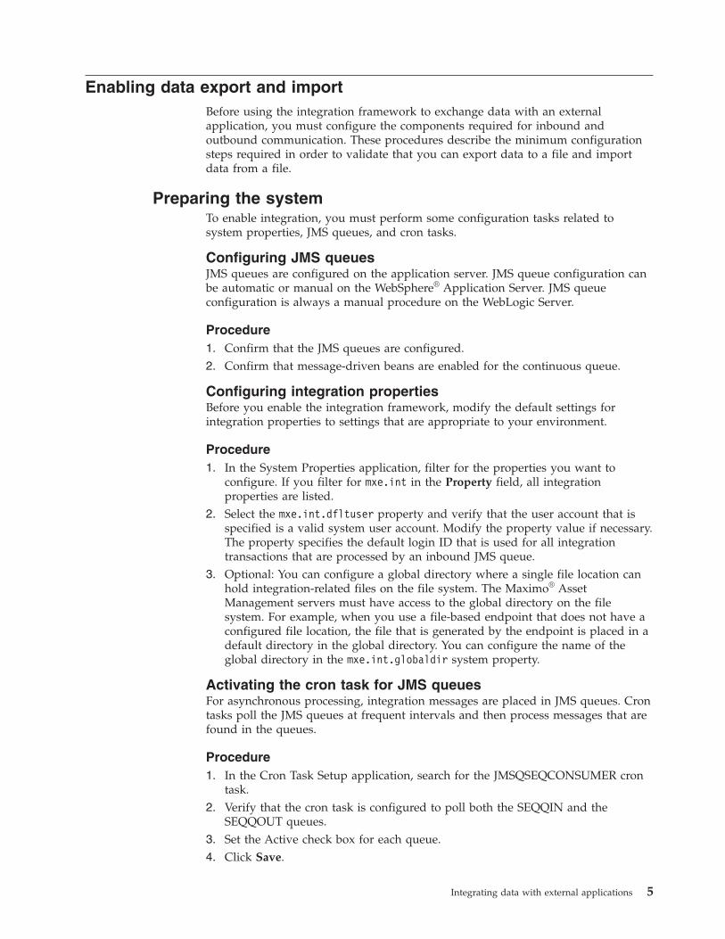
Enabling data export and importBefore using the integration framework to exchange data with an externalapplication, you must configure the components required for inbound andoutbound communication. These procedures describe the minimum configurationsteps required in order to validate that you can export data to a file and importdata from a file.
Preparing the systemTo enable integration, you must perform some configuration tasks related tosystem properties, JMS queues, and cron tasks.
Configuring JMS queuesJMS queues are configured on the application server. JMS queue configuration canbe automatic or manual on the WebSphere® Application Server. JMS queueconfiguration is always a manual procedure on the WebLogic Server.
Procedure1. Confirm that the JMS queues are configured.2. Confirm that message-driven beans are enabled for the continuous queue.
Configuring integration propertiesBefore you enable the integration framework, modify the default settings forintegration properties to settings that are appropriate to your environment.
Procedure1. In the System Properties application, filter for the properties you want to
configure. If you filter for mxe.int in the Property field, all integrationproperties are listed.
2. Select the mxe.int.dfltuser property and verify that the user account that isspecified is a valid system user account. Modify the property value if necessary.The property specifies the default login ID that is used for all integrationtransactions that are processed by an inbound JMS queue.
3. Optional: You can configure a global directory where a single file location canhold integration-related files on the file system. The Maximo® AssetManagement servers must have access to the global directory on the filesystem. For example, when you use a file-based endpoint that does not have aconfigured file location, the file that is generated by the endpoint is placed in adefault directory in the global directory. You can configure the name of theglobal directory in the mxe.int.globaldir system property.
Activating the cron task for JMS queuesFor asynchronous processing, integration messages are placed in JMS queues. Crontasks poll the JMS queues at frequent intervals and then process messages that arefound in the queues.
Procedure1. In the Cron Task Setup application, search for the JMSQSEQCONSUMER cron
task.2. Verify that the cron task is configured to poll both the SEQQIN and the
SEQQOUT queues.3. Set the Active check box for each queue.4. Click Save.
Integrating data with external applications 5
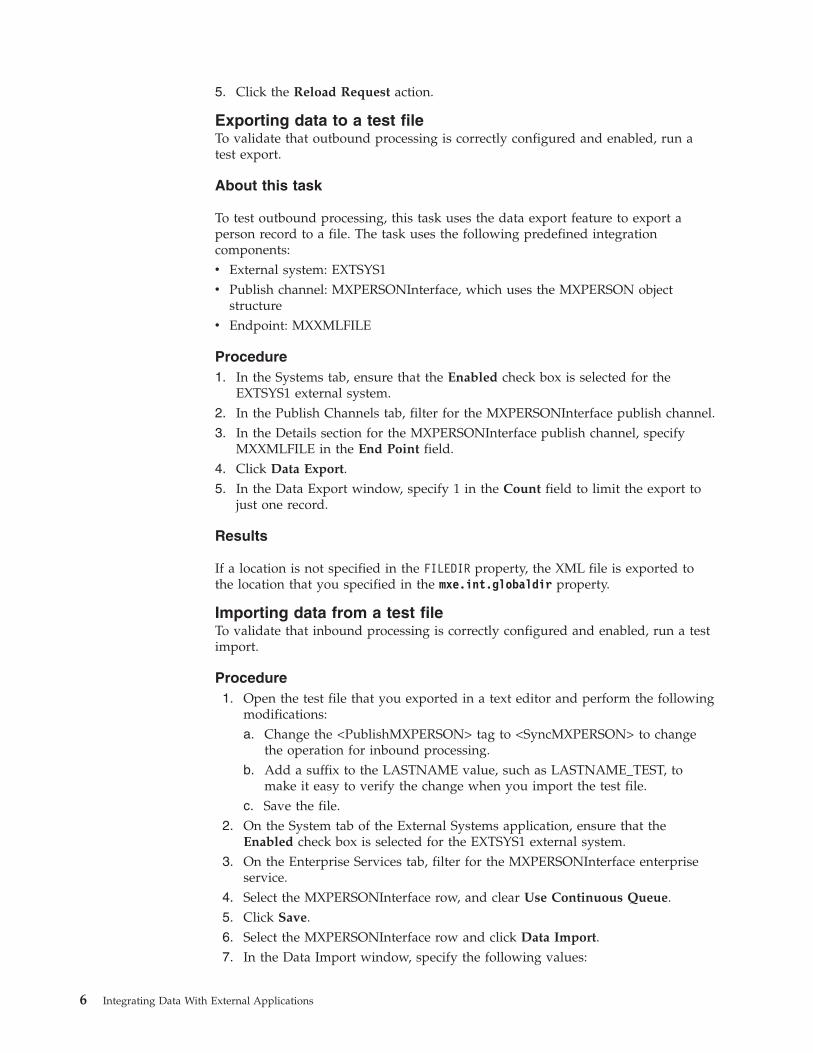
5. Click the Reload Request action.
Exporting data to a test fileTo validate that outbound processing is correctly configured and enabled, run atest export.
About this task
To test outbound processing, this task uses the data export feature to export aperson record to a file. The task uses the following predefined integrationcomponents:v External system: EXTSYS1v Publish channel: MXPERSONInterface, which uses the MXPERSON object
structurev Endpoint: MXXMLFILE
Procedure1. In the Systems tab, ensure that the Enabled check box is selected for the
EXTSYS1 external system.2. In the Publish Channels tab, filter for the MXPERSONInterface publish channel.3. In the Details section for the MXPERSONInterface publish channel, specify
MXXMLFILE in the End Point field.4. Click Data Export.5. In the Data Export window, specify 1 in the Count field to limit the export to
just one record.
Results
If a location is not specified in the FILEDIR property, the XML file is exported tothe location that you specified in the mxe.int.globaldir property.
Importing data from a test fileTo validate that inbound processing is correctly configured and enabled, run a testimport.
Procedure1. Open the test file that you exported in a text editor and perform the following
modifications:a. Change the <PublishMXPERSON> tag to <SyncMXPERSON> to change
the operation for inbound processing.b. Add a suffix to the LASTNAME value, such as LASTNAME_TEST, to
make it easy to verify the change when you import the test file.c. Save the file.
2. On the System tab of the External Systems application, ensure that theEnabled check box is selected for the EXTSYS1 external system.
3. On the Enterprise Services tab, filter for the MXPERSONInterface enterpriseservice.
4. Select the MXPERSONInterface row, and clear Use Continuous Queue.5. Click Save.6. Select the MXPERSONInterface row and click Data Import.7. In the Data Import window, specify the following values:
6 Integrating Data With External Applications
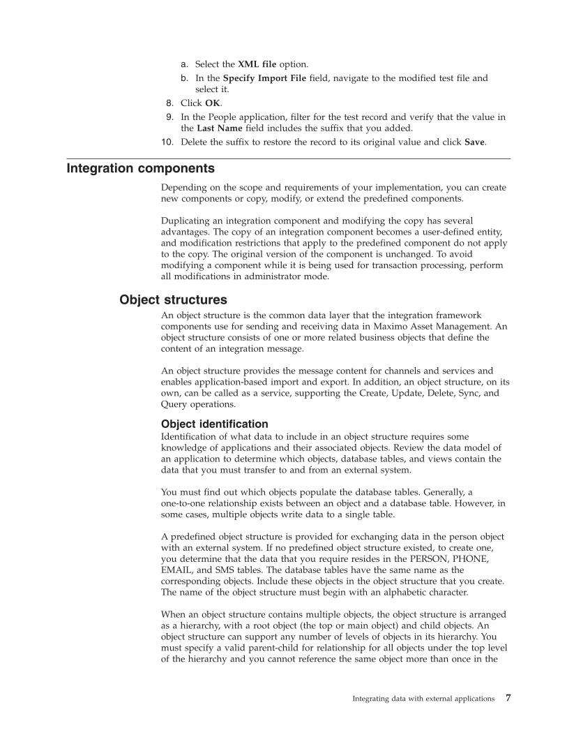
a. Select the XML file option.b. In the Specify Import File field, navigate to the modified test file and
select it.8. Click OK.9. In the People application, filter for the test record and verify that the value in
the Last Name field includes the suffix that you added.10. Delete the suffix to restore the record to its original value and click Save.
Integration componentsDepending on the scope and requirements of your implementation, you can createnew components or copy, modify, or extend the predefined components.
Duplicating an integration component and modifying the copy has severaladvantages. The copy of an integration component becomes a user-defined entity,and modification restrictions that apply to the predefined component do not applyto the copy. The original version of the component is unchanged. To avoidmodifying a component while it is being used for transaction processing, performall modifications in administrator mode.
Object structuresAn object structure is the common data layer that the integration frameworkcomponents use for sending and receiving data in Maximo Asset Management. Anobject structure consists of one or more related business objects that define thecontent of an integration message.
An object structure provides the message content for channels and services andenables application-based import and export. In addition, an object structure, on itsown, can be called as a service, supporting the Create, Update, Delete, Sync, andQuery operations.
Object identificationIdentification of what data to include in an object structure requires someknowledge of applications and their associated objects. Review the data model ofan application to determine which objects, database tables, and views contain thedata that you must transfer to and from an external system.
You must find out which objects populate the database tables. Generally, aone-to-one relationship exists between an object and a database table. However, insome cases, multiple objects write data to a single table.
A predefined object structure is provided for exchanging data in the person objectwith an external system. If no predefined object structure existed, to create one,you determine that the data that you require resides in the PERSON, PHONE,EMAIL, and SMS tables. The database tables have the same name as thecorresponding objects. Include these objects in the object structure that you create.The name of the object structure must begin with an alphabetic character.
When an object structure contains multiple objects, the object structure is arrangedas a hierarchy, with a root object (the top or main object) and child objects. Anobject structure can support any number of levels of objects in its hierarchy. Youmust specify a valid parent-child for relationship for all objects under the top levelof the hierarchy and you cannot reference the same object more than once in the
Integrating data with external applications 7
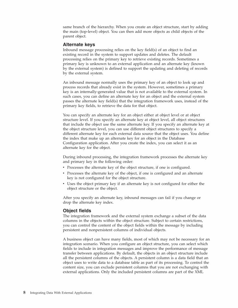
same branch of the hierarchy. When you create an object structure, start by addingthe main (top-level) object. You can then add more objects as child objects of theparent object.
Alternate keysInbound message processing relies on the key field(s) of an object to find anexisting record in the system to support updates and deletes. The defaultprocessing relies on the primary key to retrieve existing records. Sometimes aprimary key is unknown to an external application and an alternate key (knownby the external system) is defined to support the updating and deleting of recordsby the external system.
An inbound message normally uses the primary key of an object to look up andprocess records that already exist in the system. However, sometimes a primarykey is an internally-generated value that is not available to the external system. Insuch cases, you can define an alternate key for an object and the external systempasses the alternate key field(s) that the integration framework uses, instead of theprimary key fields, to retrieve the data for that object.
You can specify an alternate key for an object either at object level or at objectstructure level. If you specify an alternate key at object level, all object structuresthat include the object use the same alternate key. If you specify an alternate key atthe object structure level, you can use different object structures to specify adifferent alternate key for each external data source that the object uses. You definethe index that make up an alternate key for an object in the DatabaseConfiguration application. After you create the index, you can select it as analternate key for the object.
During inbound processing, the integration framework processes the alternate keyand primary key in the following order:v Processes the alternate key of the object structure, if one is configured.v Processes the alternate key of the object, if one is configured and an alternate
key is not configured for the object structure.v Uses the object primary key if an alternate key is not configured for either the
object structure or the object.
After you specify an alternate key, inbound messages can fail if you change ordrop the alternate key index.
Object fieldsThe integration framework and the external system exchange a subset of the datacolumns in the objects within the object structure. Subject to certain restrictions,you can control the content of the object fields within the message by includingpersistent and nonpersistent columns of individual objects.
A business object can have many fields, most of which may not be necessary for anintegration scenario. When you configure an object structure, you can select whichfields to include in integration messages and improve the performance of messagetransfer between applications. By default, the objects in an object structure includeall the persistent columns of the objects. A persistent column is a data field that anobject uses to write data to a database table as part of its processing. To control thecontent size, you can exclude persistent columns that you are not exchanging withexternal applications. Only the included persistent columns are part of the XML
8 Integrating Data With External Applications
message for outbound messages. For inbound messages, only the object columnsthat are included in the object structure are updated. Do not exclude any columnthat is part of a primary or alternate key.
By default, an object structure excludes most nonpersistent columns in thecomponent objects. A nonpersistent column is a temporary data field that an objectuses for calculations or temporary storage. You can include additionalnonpersistent columns in the object structure. For example, objects that contain thepersistent column DESCRIPTION also contain the nonpersistent columnDESCRIPTION_LONGDESCRIPTION. Most predefined object structures includethis nonpersistent column because many integration scenarios require longdescription fields. If this field is not included, it is not part of the integrationmessages.
If you change the message content of an object structure that is being used for aninterface table, the interface table must be regenerated to reflect the updatedcontent of the object structure.
Interface table and flat file considerationsIf you use an object structure for exchanging data with interface tables or flat files,you must ensure that the object structure does not contain duplicate columnnames.
You must select the Flat Supported check box for any object structure that youintend to use for interface table or flat file integration scenarios. When this optionis set, messages are checked to ensure that every column for every object in theobject structure has a unique name. If duplicate column names exist, you cancreate an alias field name for on the of the duplicate names. Modifying the aliasensures that all column names are unique and the system can generate theinterface table or flat file without errors. Interface tables require that all columnsthat are included in the corresponding object have an alias name of 18 or fewercharacters.
Modification of a predefined object structureThere are certain restrictions if you modify a predefined object structure.
You can add objects to a predefined object structure, but you cannot deletepredefined objects from the object structure. To avoid this restriction,make aduplicate of the predefined object structure to create a user-defined objectstructure, and delete objects from the duplicated version.
You can include and exclude persistent and nonpersistent columns, subject to thestandard validations that apply during integration processing. Outbound messagesinclude the columns for objects that you add to an object structure. Test inboundmessages to ensure that any columns that you added are processed successfully. Ifthe additional object columns are not processed successfully, add an objectstructure processing class to handle the inbound processing.
If you use the object structure in interface tables or flat files, check for aliasconflicts. An alias conflict can occur if two objects in an object structure thatsupports flat files have columns with the same name. When you check for aliasconflicts, duplicate names are identified and you can assign alias names to use as asubstitute to override the conflict. If you use interface tables, regenerate the tablefor every enterprise service or publish channel that uses the modified objectstructure.
Integrating data with external applications 9
Configuring an object structureYou can create new object structures and during that process you can generateschema files, include or exclude fields, and resolve alias conflicts. You can alsospecify inbound setting restrictions, set advanced configuration properties, andconfigure application authorization.
Creating object structures:
When you create an object structure, you define a group of related objects to bepart of an integration message that you exchange with external applications. Youcan identify data fields for each business object that determines the content ofintegration messages.
About this task
During the configuration, you can define the Java classes, if needed, that processinbound and outbound messages. You also can define an application that providesauthorization rules for the integration messages processed through the objectstructure. If the object structure is intended for querying only and you do not wantto use it for updating, select the Query Only option. If the main object in theobject structure has a relationship to itself as a child object, set the Self Referenceoption.
Procedure
1. In the Object Structures application, click New Object Structure.2. In the Object Structure field, specify an object structure identifier.3. Optional: If you are using the object structure for query operations, select the
Query Only check box.4. Optional: If you are using interface tables or flat files to exchange data between
the integration framework and an external system, select the Support Flat FileStructure check box.
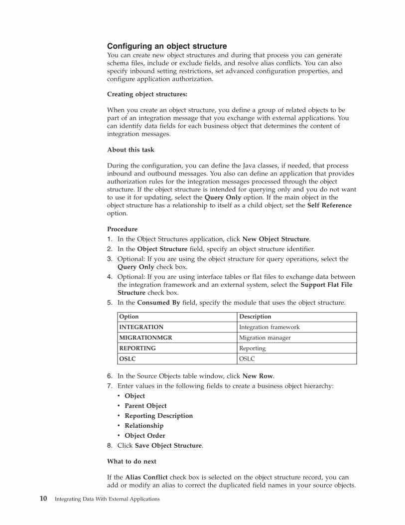
5. In the Consumed By field, specify the module that uses the object structure.
Option Description
INTEGRATION Integration framework
MIGRATIONMGR Migration manager
REPORTING Reporting
OSLC OSLC
6. In the Source Objects table window, click New Row.7. Enter values in the following fields to create a business object hierarchy:
v Object
v Parent Object
v Reporting Description
v Relationship
v Object Order
8. Click Save Object Structure.
What to do next
If the Alias Conflict check box is selected on the object structure record, you canadd or modify an alias to correct the duplicated field names in your source objects.
10 Integrating Data With External Applications
You can also specify the persistent and nonpersistent fields that you want toexclude and include from the object structure.
Configuring an alternate key:
To configure an alternate key, create a unique index in the Database Configurationapplication and reference this index as the alternate key for an object structure orfor a specific object.
About this task
If you set the alternate key at the object level, the key applies to all uses of theobject in any object structure. If you set the alternate key within the objectstructure, the key applies to the object only when it is accessed through theselected object structure.
Procedure
1. Identify the field(s) of an object to use as the alternate key.2. Select the object in the Database Configuration application.3. Create a unique index for the field(s) in the Indexes tab.4. Specify this index in the Alternative Key field in one of the following tabs:
a. In the Object tab of the Database Configuration application if you want toapply the alternate key to the object for all external data sources.
b. In the Object Structures tab of the Database Configuration application if youwant to apply the alternate key to this specific usage of the object.
Including nonpersistent fields in the object structure:
Business objects use nonpersistent fields for calculations or for temporary storageof data. By default, the nonpersistent fields on a business object are excluded fromthe object structure definition. You can include data from nonpersistent fields inintegration messages.
Before you begin
If you want to change a predefined object structure, make a duplicate of that objectstructure to create a user-defined version that is suitable for modification.
Procedure
1. In the Object Structures application, select the object structure that you want toupdate.
2. Select the business object that contains the nonpersistent field that you want toinclude.
3. Select the Exclude/Include Fields action.4. Click the Non-Persistent Fields tab to display the nonpersistent fields in the
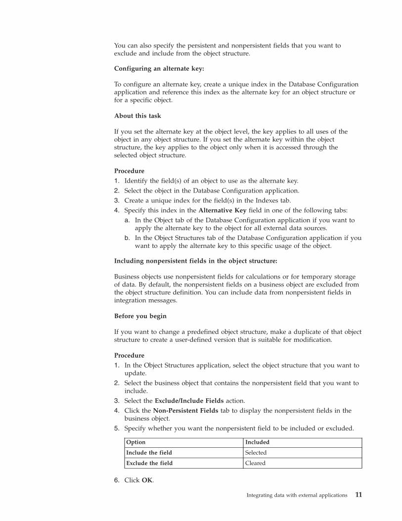
business object.5. Specify whether you want the nonpersistent field to be included or excluded.
Option Included
Include the field Selected
Exclude the field Cleared
6. Click OK.
Integrating data with external applications 11
Excluding persistent fields from the object structure:
Business objects use persistent fields to write processing data to a database. Bydefault, persistent fields are included in the object structure definition. You canexclude persistent field data that you do not want to map to an integrationmessage.
Before you begin
If you want to change a predefined object structure, make a duplicate of that objectstructure to create a user-defined version that is suitable for modification.
About this task
You cannot exclude a field that is part of a primary key. If you exclude a persistentfield from a predefined object structure, the associated object might not functionproperly during inbound message processing. Test your inbound messages toensure that an excluded persistent field does not impact the object processing.
Procedure
1. In the Object Structures application, select the object structure that you want toupdate.
2. Select the business object that contains the persistent field that you want toexclude.
3. Select the Exclude/Include Fields action.4. Click the Persistent Fields tab to display the persistent fields in the business
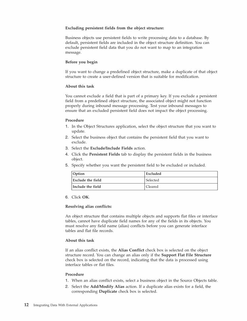
object.5. Specify whether you want the persistent field to be excluded or included.
Option Excluded
Exclude the field Selected
Include the field Cleared
6. Click OK.
Resolving alias conflicts:
An object structure that contains multiple objects and supports flat files or interfacetables, cannot have duplicate field names for any of the fields in its objects. Youmust resolve any field name (alias) conflicts before you can generate interfacetables and flat file records.
About this task
If an alias conflict exists, the Alias Conflict check box is selected on the objectstructure record. You can change an alias only if the Support Flat File Structurecheck box is selected on the record, indicating that the data is processed usinginterface tables or flat files.
Procedure
1. When an alias conflict exists, select a business object in the Source Objects table.2. Select the Add/Modify Alias action. If a duplicate alias exists for a field, the
corresponding Duplicate check box is selected.
12 Integrating Data With External Applications
3. To update a duplicate alias:a. Click View Details for the duplicate alias.b. Specify a new value in the ALIASNAME field.c. Click OK.
What to do next
After you resolve all alias conflicts, you can generate interface tables and flat filerecords. If you use interface tables, you must regenerate all tables that use theupdated object structure. To regenerate interface tables, select the Create InterfaceTables action in the External Systems application.
Setting restrictions on fields in inbound messages:
Standard integration processing sets the values in object fields with thecorresponding values from an inbound message. You can set a field as restricted ifyou do not want the value to be updated by inbound messages, for example for afield with an internal ID or where a processing class provides the logic to set thefield.
Procedure
1. Select the Inbound Setting Restrictions action.2. In the Inbound Setting Restrictions window, select the object that you want to
apply setting restrictions to. The Inbound Setting Restrictions table refresheswith a list of the fields that are configured for the selected object.
3. Select the Restricted check box for any field that you do not want to beupdated with values in inbound messages.
4. You can select the Override check box to remove the restrictions set for a field.You cannot override the restriction set on some fields, for example for a fieldwith a system-generated ID.
5. Click OK.
Setting advanced configurations for an object structure:
You can set advanced configurations for an object structure to change some defaultprocessing behavior for integration messages. Advanced configurations includeconfiguring how key fields are processed for child objects, whether an event on achild object activates a corresponding event on the parent object, and whetherauto-generated data is deleted.
Procedure
1. Select the Advanced Configuration action.2. Deselect the Exclude Parent Key Attributes check box for any object where you
want these attributes to be included for child objects. When checked (thedefault), key fields that exist in a child object are not included in the section ofthe message for the child object if the same field is part of the key of the parentobject. If you deselect this option, key fields for a child object are alwaysincluded and the field is included in both the child object section of themessage and the parent object section.
3. Deselect the Delete Auto-generated Data check box for any object where youwant to retain this data. When checked (the default), integration processingalways deletes any child-level data that is automatically created by the business
Integrating data with external applications 13
object logic when the parent object is created. If you deselect this option, anyadditional data that is auto-generated is retained.
4. Check the Propagate Event option for any object where you want an event on achild object to trigger an event on the main object. When you configure apublish channel to send messages based on an object event, the event listener isconfigured for the main object of the object structure. In some cases, an updateto a child object does not trigger an event on the main object and no message isinitiated. Check this option if you want an update to the child object to triggeran event to the main object without updating the main object. If a child objectincludes logic that triggers an event to its parent object, you cannot enable ordisable it with this configuration.
Channels and servicesChannels and services reference an object structure for their message content andenable the synchronous and asynchronous exchange of data with external systems.Two types of channel process outbound messages; publish channels and invocationchannels. Three types of service process inbound messages; object structureservices, enterprise services, and standard services.
Publish channelsA publish channel is used for sending asynchronous messages through a JMSqueue to an external system. Publish channel messages can be initiated via anevent or through the Data Export feature.
The integration framework includes predefined publish channels or you canconfigure new publish channels. When configuring a publish channel, you mustassociate it with an object structure, and, optionally, enable an event listener. Youmust also configure the publish channel with an external system to determinewhere the message is delivered to.
You can also configure processing rules, Java processing classes, or XSL mappingto customize transaction processing of the publish channel.
Configuring a publish channel:
To use a publish channel for data export, you must create the publish channel,associate it with an object structure, and enable an event listener. You must alsoconfigure an endpoint that routes the transaction to a specified external system.You can also configure publishing rules, Java processing classes, or XSL mappingto customize transaction processing.
Creating publish channels:
You can create a publish channel record to send integration messages to anexternal system.
Before you begin
Before you create and configure a publish channel, use the Object Structuresapplication to configure the object structure that you intend to associate with thepublish channel.
Procedure
1. In the Publish Channels application, click New Publish Channel.2. In the Publish Channel field, specify a name for the publish channel.
14 Integrating Data With External Applications
3. In the Object Structure field, specify the object structure to use with thepublish channel. The Object Structure Sub-Records section refreshes with detailsof the objects that are contained in this object structure.
4. Optional: If you intend to use an interface table as the data source, specify itsname in the Interface Table field. The object structure must be configured tosupport flat files to be used with interface tables
5. Optional: If you intend to customize outbound processing logic, specify thepaths for the Java Classes and the XSL style sheet in the following fields:a. Processing Class
b. User Exit Class
c. XSL Map
d. Event Filter Class
Any Java classes you specify must be part of the application EAR file. An XSLfile can be within the EAR file or located on an accessible file system.
6. Optional: You can configure processing rules for the publish channel.7. Optional: If necessary, clear the Retain Objects check box to prevent the
publish channel from processing business object-based rules.8. Click Save Publish Channel.
What to do next
You can enable a publish channel listener to direct the integration framework tobuild and process the selected publish channel. You can also use the ExternalSystems application to associate the publish channel with an external system andidentify an endpoint for delivering messages from the publish channel.
Enabling publish channel listeners:
You enable an event listener on a publish channel to monitor for processingactivity on the associated publish channel objects. Publish channel processing isinitiated when an event occurs on the main object of the associated objectstructure.
Procedure
1. In the Publish Channels application, select the publish channel that you want toconfigure with an event listener.
2. Select the Enable Event Listener action.3. Click OK to enable the publish channel listener. The details for the publish
channel refresh and the Event Listener check box is now selected.
What to do next
Select Disable Event Listener action if you want to disable the event listener atany time..
Invocation channelsInvocation channels define the processing logic and mapping of inbound andoutbound data, which enables the integration framework to call externalapplications and process responses. No predefined invocation channels areprovided.
Integrating data with external applications 15
Creating invocation channels:
You can create an invocation channel record to send outbound data from an objectstructure to an external system and to process responses from the external system.
Before you begin
You must include the defined processing class, user exit class, and XSL mappingfiles in the application EAR file. You also must define an XSL mapping filenamepath that is accessible by the application server.
Procedure
1. In the Invocation Channels application, click New Invocation Channel.2. In the Invocation Channel field, specify an invocation channel identifier.3. Enter values in the following fields:
v Adapter
v Endpoint
4. Optional: If this invocation channel processes responses from an externalapplication, select the Process Response check box.
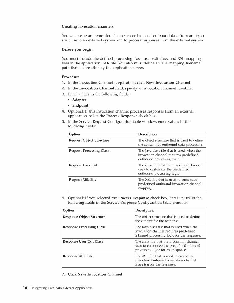
5. In the Service Request Configuration table window, enter values in thefollowing fields:
Option Description
Request Object Structure The object structure that is used to definethe content for outbound data processing.
Request Processing Class The Java class file that is used when theinvocation channel requires predefinedoutbound processing logic.
Request User Exit The class file that the invocation channeluses to customize the predefinedoutbound processing logic
Request XSL File The XSL file that is used to customizepredefined outbound invocation channelmapping.
6. Optional: If you selected the Process Response check box, enter values in thefollowing fields in the Service Response Configuration table window:
Option Description
Response Object Structure The object structure that is used to definethe content for the response.
Response Processing Class The Java class file that is used when theinvocation channel requires predefinedinbound processing logic for the response.
Response User Exit Class The class file that the invocation channeluses to customize the predefined inboundprocessing logic for the response.
Response XSL File The XSL file that is used to customizepredefined inbound invocation channelmapping for the response.
7. Click Save Invocation Channel.
16 Integrating Data With External Applications
What to do next
You can view the XML schema of the object structure using a URL with thefollowing format:
http://localhost:port/meaweb/schema/service/object_structure_name
Configuring an action to call an invocation channel:
The integration framework provides a default action class that you can configureas a system action. By providing this action class, you can configure a userinterface control, an escalation, or a workflow to invoke an external service usingan invocation channel.
Procedure
1. Create an invocation channel in the Invocation Channels application.2. Create an action in the Actions application.3. Specify an object for the action. This object must be the same as the main object
of the request object structure of the invocation channel and the main object ofthe application, workflow, or escalation that invokes the action.
4. Specify Custom Class in the Type field.5. Specify the name of the custom class in the Variable field. You can use the
name of the default class provided for this purpose,psdi.iface.action.InvokeCustomClass, or an alternative class name if youcreated your own custom class to invoke an external system.
6. Specify values in the Parameters/Attributes field. Specify the values in thefollowing order, and separate each value with a comma:a. Required: The name of the invocation channel to use. The value must be
precisely the same as the name of the invocation channel.b. Optional: The name of the relationship to use if the main object of the
response object structure is different from the main object of the requestobject structure in the invocation channel. If the response object is the sameas the request object, no relationship is required.
c. Optional: If you specified a relationship, specify the action to apply. Thedefault action is Add, which creates records. To update existing records,specify Change as the action. If the request and response object structuresare the same, the objects are updated if updated fields are mapped into theresponse object structure.
7. Specify whether to apply the action to all applications, to workflows, orapplications.
8. Save the action.
What to do next
Associate an application, workflow, or escalation with the action. The main objectis passed to the action class and then to the object structure of the invocationchannel to form the request XML.
Integrating data with external applications 17
Invoking an external system from an application:
After configuring an action class to invoke an external system (via an invocationchannel), you can configure a button in an application to trigger the invocationaction. You can also extend the action class to display the results of the transactionin an application dialog box.
Before you begin
You must create an invocation channel and an action class before you add theinvocation action to an application. If you intend to show the results of theinvocation, create a Results (dialog) window in advance.
Procedure
1. Open the application in the Application Designer application. The main objectfor this application must be same as the main object for the invocation channeland the action that you intend to call from the application.
2. Add a Button Group control to the workspace from the Control Palette. TheButton Group control automatically adds a Pushbutton control to theworkspace.
3. Click Properties to open the Pushbutton Properties window.4. Specify a name for the button in the Value field, for example Invoke External
System.5. Specify the Control ID for the Results window in the Target ID field.6. Specify a method in the Value field that calls the invocation channel and
redirects the results to the Results window. For example:InvokeChannelCache.getInstance().getInvokeChannel(channelName).invoke(metaData, mbo, mbo.getMboSet(rel), action, null);
Where:v The channelName value is the name of the invocation channel.v The mbo value is the name of the object.v The rel value is the name of the relationship (if applicable).v The action value is Add.
Object structure servicesWhen you configure an object structure, no additional configuration is necessary tomake it available as a service or a REST resource.Related concepts:“REST API” on page 226The Representational State Transfer (REST) application programming interface(API) provides a way for external applications to query and update applicationdata in Tivoli's process automation engine.
Enterprise servicesAn enterprise service is a pipeline for querying external data and importing datafrom an external system. An enterprise service can process data synchronously(without a queue) or asynchronously (with a queue). Enterprise services can usemultiple protocols, such as web services and HTTP.
An enterprise service has data processing layers that transform data and applybusiness processing rules to data before the it reaches the target objects. When the
18 Integrating Data With External Applications
inbound message reaches the object structure layer, the XML message must be inthe format of the object structure schema. The integration framework can then canprocess the message successfully.
You can configure an enterprise service to implement the following transactionprocessing:v Processing rulesv User exit Java processing classv Enterprise service processing classv XSL mapping
The gateway is the entry point for enterprise service messages, excluding thosethat are delivered directly from an external queue to the integration queue. Forsome integration scenarios, it can be useful to configure gateway properties, forexample if properties such as system IDs are provided within the XML messagerather than in the header information. You can configure an interpreter Java classto change the external system ID, the enterprise service ID, or other JMS messageheader properties that are provided in an inbound message. Alternatively, you canconfigure gateway properties in the Enterprise Services application.
Configuring an enterprise service:
When you create an enterprise service, you associate it with an object structure.You can also configure gateway properties that are added to the headerinformation of inbound messages.
Creating an enterprise service:
You can create an enterprise service record to receive inbound data from anexternal system. On the enterprise service, you can identify the data transformationand processing rules that the integration framework uses to receive inbound datafrom an external system.
Before you begin
Before you create and configure an enterprise service, use the Object Structuresapplication to configure the object structure that you associate with the enterpriseservice.
About this task
When the Use External Schema check box is selected, the Split Tag, ExternalSchema File, and External Schema Element fields are editable. The externalschema values identify the schema location and external root element name.
Procedure
1. In the Enterprise Services application, click New Enterprise Service.2. In the Enterprise Service field, specify an enterprise service identifier.3. Enter a values in the following fields:
v Object Structure
v Adapter
4. Optional: Enter values in the following fields:
Integrating data with external applications 19
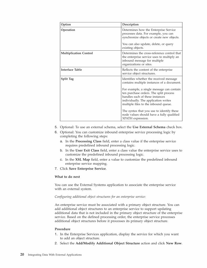
Option Description
Operation Determines how the Enterprise Serviceprocesses data. For example, you cansynchronize objects or create new objects.
You can also update, delete, or queryexisting objects.
Multiplication Control Determines the cross-reference control thatthe enterprise service uses to multiply aninbound message for multipleorganizations or sites.
Interface Table Reflects the content of the enterpriseservice object structures.
Split Tag Identifies whether the received messagecontains multiple instances of a document.
For example, a single message can containten purchase orders. The split processhandles each of these instancesindividually. The application writesmultiple files to the inbound queue.
The syntax that you use to identify thesenode values should have a fully qualifiedXPATH expression.
5. Optional: To use an external schema, select the Use External Schema check box.6. Optional: You can customize inbound enterprise service processing logic by
completing the following steps:a. In the Processing Class field, enter a class value if the enterprise service
requires predefined inbound processing logic.b. In the User Exit Class field, enter a class value the enterprise service uses to
customize the predefined inbound processing logic.c. In the XSL Map field, enter a value to customize the predefined inbound
enterprise service mapping.7. Click Save Enterprise Service.
What to do next
You can use the External Systems application to associate the enterprise servicewith an external system.
Configuring additional object structures for an enterprise service:
An enterprise service must be associated with a primary object structure. You canadd additional object structures to an enterprise service to support updatingadditional data that is not included in the primary object structure of the enterpriseservice. Based on the defined processing order, the enterprise service processesadditional object structures before it processes its primary object structure.
Procedure
1. In the Enterprise Services application, display the service for which you wantto add an object structure.
2. Select the Add/Modify Additional Object Structure action and click New Row.
20 Integrating Data With External Applications
3. Enter values in the following fields:v Object Structure
v Processing Order
4. Optional: You can customize inbound enterprise service processing logic bycompleting the following steps:a. In the Processing Class field, enter a class value if the enterprise service
requires predefined inbound processing logic.b. In the User Exit Class field, enter a class value the enterprise service uses to
customize the predefined inbound processing logic.c. In the XSL Map field, enter a value to customize the predefined inbound
enterprise service mapping.d. In the Multiplication Control field, enter a value to define the
cross-reference control that the enterprise service uses to multiply aninbound message for multiple organizations or sites.
5. Click OK.
Adding gateway properties to an enterprise service:
The gateway is the entry point for enterprise service messages, excluding thosethat are delivered directly from an external queue to the integration queue. Aninterpreter Java class can be implemented that can change the external system(SENDER) or the enterprise service (INTERFACE) and can set other JMS headerproperties as needed. In the Enterprise Services application, you can set gatewayproperties either as hard-coded values or by specifying XML tags.
Before you begin
Review the following points about the settings in the Gateway Properties beforeyou configure the gateway properties:v If you select the XML Tag check box and leave the Value field null, the gateway
uses the name of the root element in the XML message as the value for thecorresponding property.
v If you select the XML Tag check box and enter a tag name in the Value field, thegateway uses the value for that tag as the value for the corresponding property.
v If the tag appears multiple times in the XML message, the adapter uses thevalue of the first occurrence of the tag. If you clear the XML Tag check box andenter a data value in the Value field, the gateway uses that data as the value forthe corresponding property.
Procedure
1. In the Enterprise Services application, display the service for which you wantto add a gateway property.
2. Select the Gateway Properties action.3. In the Gateway Properties for Enterprise Service table window, click New Row.4. In the Property field, specify the name of the property that you want to include
in the message.5. In the Value field, type the data that you want to use as the value of the
property.6. Optional: Specify whether you want to use the XML root element as the value
of the corresponding property.
Integrating data with external applications 21
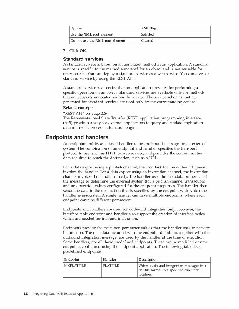
Option XML Tag
Use the XML root element Selected
Do not use the XML root element Cleared
7. Click OK.
Standard servicesA standard service is based on an annotated method in an application. A standardservice is specific to the method annotated for an object and is not reusable forother objects. You can deploy a standard service as a web service. You can access astandard service by using the REST API.
A standard service is a service that an application provides for performing aspecific operation on an object. Standard services are available only for methodsthat are properly annotated within the service. The service schemas that aregenerated for standard services are used only by the corresponding actions.Related concepts:“REST API” on page 226The Representational State Transfer (REST) application programming interface(API) provides a way for external applications to query and update applicationdata in Tivoli's process automation engine.
Endpoints and handlersAn endpoint and its associated handler routes outbound messages to an externalsystem. The combination of an endpoint and handler specifies the transportprotocol to use, such as HTTP or web service, and provides the communicationdata required to reach the destination, such as a URL.
For a data export using a publish channel, the cron task for the outbound queueinvokes the handler. For a data export using an invocation channel, the invocationchannel invokes the handler directly. The handler uses the metadata properties ofthe message to determine the external system (for a publish channel transaction)and any override values configured for the endpoint properties. The handler thensends the data to the destination that is specified by the endpoint with which thehandler is associated. A single handler can have multiple endpoints, where eachendpoint contains different parameters.
Endpoints and handlers are used for outbound integration only. However, theinterface table endpoint and handler also support the creation of interface tables,which are needed for inbound integration.
Endpoints provide the execution parameter values that the handler uses to performits function. The metadata included with the endpoint definition, together with theoutbound integration message, are used by the handler at the time of execution.Some handlers, not all, have predefined endpoints. These can be modified or newendpoints configured using the endpoint application. The following table listspredefined endpoints.
Endpoint Handler Description
MXFLATFILE FLATFILE Writes outbound integration messages in aflat file format to a specified directorylocation.
22 Integrating Data With External Applications
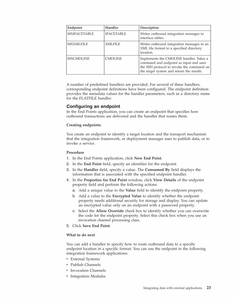
Endpoint Handler Description
MXIFACETABLE IFACETABLE Writes outbound integration messages tointerface tables.
MXXMLFILE XMLFILE Writes outbound integration messages in anXML file format to a specified directorylocation.
MXCMDLINE CMDLINE Implements the CMDLINE handler. Takes acommand and endpoint as input and usesthe SSH protocol to invoke the command onthe target system and return the results.
A number of predefined handlers are provided. For several of these handlers,corresponding endpoint definitions have been configured. The endpoint definitionprovides the metadata values for the handler parameters, such as a directory namefor the FLATFILE handler.
Configuring an endpointIn the End Points application, you can create an endpoint that specifies howoutbound transactions are delivered and the handler that routes them.
Creating endpoints:
You create an endpoint to identify a target location and the transport mechanismthat the integration framework, or deployment manager uses to publish data, or toinvoke a service.
Procedure
1. In the End Points application, click New End Point.2. In the End Point field, specify an identifier for the endpoint.3. In the Handler field, specify a value. The Consumed By field displays the
information that is associated with the specified endpoint handler.4. In the Properties for End Point window, click View Details of the endpoint
property field and perform the following actions:a. Add a unique value to the Value field to identify the endpoint property.b. Add a value to the Encrypted Value to identify whether the endpoint
property needs additional security for storage and display. You can updatean encrypted value only on an endpoint with a password property.
c. Select the Allow Override check box to identify whether you can overwritethe code for the endpoint property. Select this check box when you use aninvocation channel processing class.
5. Click Save End Point.
What to do next
You can add a handler to specify how to route outbound data to a specificendpoint location in a specific format. You can use the endpoint in the followingintegration framework applications:v External Systemsv Publish Channelsv Invocation Channelsv Integration Modules
Integrating data with external applications 23
v Logical Management Operations
Adding a handler to an endpoint:
You can add a handler to an endpoint record to specify how to route outbounddata to a specific endpoint location. You can also add a handler to define the dataformat that is used in the data transfers. When you create a handler, you mustidentify the specific Java™ class file that contains the processing logic that you needfor data transfers.
About this task
You cannot modify or delete a predefined handler.
Procedure
1. In the End Points application, select the endpoint that you want to update withhandler information.
2. Select the Add/Modify Handlers action.3. Click New Row.4. Enter values in the following fields:
v Handler
v Handler Class Name
v Consumed By
5. Click OK.
Writing custom handlers:
You can write a custom handler and associate it with an endpoint, for example tosupport communication with an FTP server.
About this task
The handler class displays the properties for which you must specify values. TheFTPHandler.java file in the psdi.iface.samples directory contains an example ofan FTP handler.
Procedure
1. To write a custom handler, implement the RouterHandler interface.2. Specify the following method to return a list of properties that the handler uses
to send data to the endpoint:getParameter()
The method returns a list of RouterPropsInfo objects. The isCrypto attribute inthe RouterPropsInfo object indicates whether to encrypt the property valuewhile storing data. For password properties, the value of this attribute is True.
3. Specify the following method to send data to the specified endpoint:sendData(Map metaData, byte[] data, Map destinationMap)
The method returns the following information:v Metadata provides information about the external system and the interface.v Data is the XML data.v DestinationMap specifies the endpoint.
24 Integrating Data With External Applications
Predefined endpoint handlersPredefined handlers are provided that you can associate with an endpoint.Additionally, you can create and register custom handlers when needed.
Enterprise bean handler:
The Enterprise Java Bean (EJB) handler is a Java component that consists ofenterprise bean clients. The handler publishes a set of properties that a client usesto communicate with and deliver an integration message to a target client. Thetarget client can run on the local application server or on a remote applicationserver.
To establish a connection, the remote Java class and the home Java class must beavailable in the class path of the handler. If the client is on a remote applicationserver that is different from the handler application server, the client jar filereference must be in the class path of the handler. The handler picks up the contextfactory class name from the local application server when the enterprise bean clientis on a remote application server that is the same as the handler application server.
CONTEXTFACTORY property
This required property specifies a J2EE context factory class name. Thedocumentation for your application server contains the name of the default contextfactory to use.
The CONTEXTFACTORY uses the following property when the target client runson an IBM WebSphere Application Server:com.ibm.websphere.naming.WsnInitialContextFactory
EJBEXIT property
This optional property is used for customization and specifies the fully qualifiedname of a custom Java class that implements the EJBExit interface.
If you do not specify a value for this property, the DefaultEJBExit interface isexecuted and attempts to resolve the enterprise bean method signature andparameters.
If the enterprise bean client has its own method signature and parameters, create aJava class that contains your version of the EJBExit interface and implementationsof the following methods:public Class[] getClassParams()
The getClassParams() method returns the method signature in the form of an arrayof Java classes.
public Object[] getObjectParams(byte[] data, String interfaceName, MapString,? metaData)throws MXException
The getObjectParams() method returns the parameters of the enterprise beanbusiness method in the form of an array of Java objects.public void responseOk(Object response)throws MXException
The responseOk() method is called after a successful enterprise bean invocation.public void responseError(Exception e) throws MXException
Integrating data with external applications 25
The responseError() method is called with the originating exception as a parameterif an error is encountered during enterprise bean invocation.
The following code illustrates what your implementation of getClassParams() lookslike when the enterprise bean client has a business method with a byte array and astring:Class[] classParams = {byte[].class, String.class};return classParams;
The following code illustrates what your implementation of getObjectParams ()looks like when the enterprise bean client has a business method with a byte arrayand a string:byte[] data = ...;String ifaceType = ...;
Object[] objParams = {data,ifaceType};return objParams;
Complete one of the following actions to identify the location of the packagestructure for the EJBExit class file:v Place the class in the Java package structure in the applications/maximo/
businessobjects/classes directory.v Modify the mboweb\webmodule\META-INF\MANIFEST.MF class path to include the
package structure.v Rebuild the application EAR file and include the EJBExit class file.
JNDINAME property
This required property specifies the name by which the enterprise bean client isregistered in the Java Naming and Directory Interface (JNDI) tree on theWebSphere Application Server. The filename is ibm-ejb-jar-bnd.xml and theproperty is set to<ejbBindings xmi:id="Session_enterpriseservice_Bnd"
jndiName="ejb/maximo/remote/enterpriseservice"><enterpriseBean xmi:type="ejb:Session"
href="META-INF/ejb-jar.xml#Session_enterpriseservice"/></ejbBindings>
METHODNAME property
This required property specifies the public business method that is exposed by theenterprise bean client that is invoked by this handler.
PROVIDERURL property
This required property specifies the URL of the target application server on whichthe enterprise bean is running. The system then maps to thejava.naming.provider.url property and creates the InitialContext object.
The following example is an IBM WebSphere Application Server provider URL.corbaloc:iiop:hostname:iiopport
If the handler and the target enterprise bean are running on the same applicationserver instance, do not specify this property because it defaults to the local serverURL.
26 Integrating Data With External Applications
USERNAME and PASSWORD properties
The user name and password properties correspond to thejava.naming.security.principal (USERNAME) andjava.naming.security.credentials (PASSWORD) properties that are used to createthe InitialContext object.
Flat file handler:
The FLATFILE handler converts an outbound integration message into a flat fileand writes it to a directory that has a configurable location. Flat files contain ASCIIdata in the form of rows and columns. Each line of text constitutes one row, and aseparator character separates each column in the row. The FLATFILE handlerencodes outbound flat files in the standard UTF-8 format.
The FLATFILE handler can be used only with publish channels, not invocationchannels. The object structure associated with the publish channel must beconfigured to support flat files. You must resolve all alias conflicts for the objectstructure and format the XML message according to the object structure schemabefore writing the message to a flat file.
Naming conventions
File names require the following format.
externalsystemname_publishchannelname_uniqueidentifier.dat
v externalsystemname is the identifier of the system (the value ofMAXVARS.MXSYSID).
v publishchannelname is the name of the publish channel.v uniqueidentifier is a number based on current system time.
The following example file name indicates that the file goes to the external systemEXTSYS1 and was published through the MXASSETInterface publish channel:
EXTSYS1_MXASSETInterface_10971102668641498.dat
The first two lines of the file contain header information. The first line has thefollowing format:
externalsystemname <separator> publish channel name <separator> [action]<separator> langcode
The second line of the file contains the names of the columns, separated by theseparator character. The column names are the same as the names in thecorresponding interface table.
Flat file format
If the data in the flat file contains the flat file delimiter character, the data adds thetext qualifier, which is " (quotation marks). If the data contains quotation marks,the handler escapes the quotation marks. You cannot use quotation marks as thedelimiter character.
Integrating data with external applications 27
The following example data uses a comma (,) as a delimiter. The INVOICEDESCvalue, (Rotating Custom Item, No 71), contains a comma. When the flat file iswritten, the INVOICEDESC value is enclosed in quotation marks.EXTSYS1,MXINVOICEInterface,AddINVOICENUM,INVOICEDESC,PONUM,VENDOR,CONTACT,PAYMENTTERMS1071,"Rotating Custom Item, No 71",1000,A0001,,
The following example data uses a comma (,) as a delimiter. The INVOICEDESCvalue (Rotating "Custom" Item No 71) contains double quotation marks. When theflat file is written, double quotation marks in INVOICEDESC data ends withquotation marks, and the entire string is wrapped in quotation marks.EXTSYS1,MXINVOICEInterface,AddINVOICENUM,INVOICEDESC,PONUM,VENDOR,CONTACT,PAYMENTTERMS1071,"Rotating ""Custom"" Item No 71",1000,A0001,,
The following example data uses a comma (,) as a delimiter. The INVOICEDESCdata (Rotating "Custom" Item, No. 71) contains the delimiter character anddouble quotation marks. When the flat file is written, the INVOICEDESC valueappears in the code.EXTSYS1,MXINVOICEInterface,AddINVOICENUM,INVOICEDESC,PONUM,VENDOR,CONTACT,PAYMENTTERMS1071,"Rotating ""Custom"" Item, No. 71",1000,A0001,,
Flat file properties
The FLATFILEDIR property is an optional property that specifies the location ofthe flat file. The location must exist on the local server where the JMS CRON taskfor the outbound queue is running, or on an accessible shared network drive. Thedefault value points to the global directory/flatfiles directory. To specify a locationfor the global directory, configure the mxe.int.globaldir property in the SystemProperties application.
The FLATFILESEP property is a required property that specifies the character thatseparates the columns in each row.
HTTP handler:
The HTTP handler is a Java component that consists of properties. The handlerdelivers an outbound integration message as an XML document to a URL by usingHTTP or HTTPS protocols. The HTTP handler also evaluates the response codereceived from the external system.
HTTPEXIT property
This optional property is used for customization and specifies the fully qualifiedname of a Java class that interprets the HTTP response. This property also helpsimplement the code that is required for an external system to interpret the HTTPresponse.
The Java class must be available in the application EAR file and must be in theclass path of the handler.
Property Value
Java class DefaultHTTPExit.java
Package psdi.iface.router
28 Integrating Data With External Applications
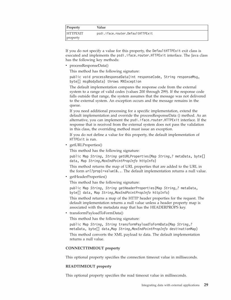
Property Value
HTTPEXITproperty
psdi.iface.router.DefaultHTTPExit
If you do not specify a value for this property, the DefaultHTTPExit exit class isexecuted and implements the psdi.iface.router.HTTPExit interface. The Java classhas the following key methods:v processResponseData()
This method has the following signature:public void processResponseData(int responseCode, String responseMsg,byte[] msgBodyData) throws MXException
The default implementation compares the response code from the externalsystem to a range of valid codes (values 200 through 299). If the response codefalls outside that range, the system assumes that the message was not deliveredto the external system. An exception occurs and the message remains in thequeue.If you need additional processing for a specific implementation, extend thedefault implementation and override the processResponseData () method. As analternative, you can implement the psdi.iface.router.HTTPExit interface. If theresponse that is received from the external system does not pass the validationin this class, the overriding method must issue an exception.If you do not define a value for this property, the default implementation ofHTTPExit is run.
v getURLProperties()This method has the following signature:public Map String, String getURLProperties(Map String,? metaData, byte[]data, Map String,MaxEndPointPropInfo httpInfo)
This method returns the map of URL properties that are added to the URL inthe form url?prop1=value1&... The default implementation returns a null value.
v getHeaderProperties()This method has the following signature:public Map String, String getHeaderProperties(Map String,? metaData,byte[] data, Map String,MaxEndPointPropInfo httpInfo)
This method returns a map of the HTTP header properties for the request. Thedefault implementation returns a null value unless a header property map isassociated with the metadata map that has the HEADERPROPS key.
v transformPayloadToFormData()This method has the following signature:public Map String, String transformPayloadToFormData(Map String,?metaData, byte[] data,Map String,MaxEndPointPropInfo destinationMap)
This method converts the XML payload to data. The default implementationreturns a null value.
CONNECTTIMEOUT property
This optional property specifies the connection timeout value in milliseconds.
READTIMEOUT property
This optional property specifies the read timeout value in milliseconds.
Integrating data with external applications 29
HTTPMETHOD property
This required property specifies a valid HTTP method that is executed by theendpoint. Valid HTTP methods are GET, POST, PUT, and DELETE.
HTTPHEADER property
This optional property can add a comma-separated list of names and values to theheader section of HTTP messages. The list includes name and value information inthe format of Headername1:Headervalue1, Headername2:Headervalue2. If no valueis provided in the property, custom code can inject the values into the transactioncontext during invocation channel processing.
URL property
This optional property specifies a valid URL to which XML data can be posted orwhere an HTTP GET operation can be performed.
USERNAME and PASSWORD properties
If the URL requests basic authentication, these properties specify the requiredvalues. Both values are MIME encoded and are passed to the URL.
IFACETABLE handler:
The IFACETABLE handler consists of several properties. This handler writes anoutbound integration message to an interface table in a local or remote database.There are no Java exit classes for this handler.
Only publish channels can use the IFACETABLE handler. Invocation channelscannot use this handler.
ISREMOTE property
This required property is a Boolean value that specifies whether interface tables areavailable in the local database or in a remote database. A value of 0 (false)indicates that the interface tables are available in the local database in the systemschema. You do not have to enter any other handler properties. In the predefinedMAXIFACETABLE handler, the value of this property is 0. A value of 1 (true)indicates the interface tables are in a remote database. If necessary, specify valuesfor all the handler properties.
DRIVER property
This property specifies the JDBC driver to connect to a remote database thatcontains the interface tables. This property applies only when the value of theISREMOTE property is 1.
URL property
This property specifies the JDBC URL and applies only when the value of theISREMOTE property is 1. The following example contains the location, portnumber, and database name:
jdbc:db2://hostname:port/maximodb
30 Integrating Data With External Applications
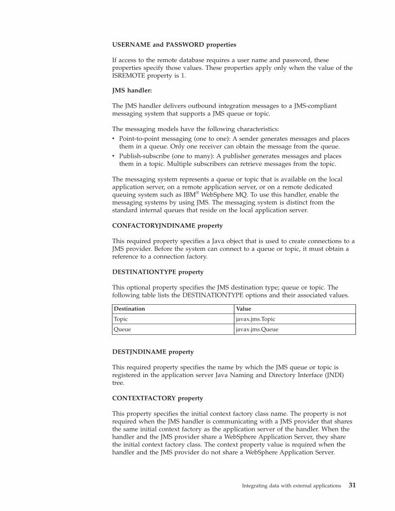
USERNAME and PASSWORD properties
If access to the remote database requires a user name and password, theseproperties specify those values. These properties apply only when the value of theISREMOTE property is 1.
JMS handler:
The JMS handler delivers outbound integration messages to a JMS-compliantmessaging system that supports a JMS queue or topic.
The messaging models have the following characteristics:v Point-to-point messaging (one to one): A sender generates messages and places
them in a queue. Only one receiver can obtain the message from the queue.v Publish-subscribe (one to many): A publisher generates messages and places
them in a topic. Multiple subscribers can retrieve messages from the topic.
The messaging system represents a queue or topic that is available on the localapplication server, on a remote application server, or on a remote dedicatedqueuing system such as IBM® WebSphere MQ. To use this handler, enable themessaging systems by using JMS. The messaging system is distinct from thestandard internal queues that reside on the local application server.
CONFACTORYJNDINAME property
This required property specifies a Java object that is used to create connections to aJMS provider. Before the system can connect to a queue or topic, it must obtain areference to a connection factory.
DESTINATIONTYPE property
This optional property specifies the JMS destination type; queue or topic. Thefollowing table lists the DESTINATIONTYPE options and their associated values.
Destination Value
Topic javax.jms.Topic
Queue javax.jms.Queue
DESTJNDINAME property
This required property specifies the name by which the JMS queue or topic isregistered in the application server Java Naming and Directory Interface (JNDI)tree.
CONTEXTFACTORY property
This property specifies the initial context factory class name. The property is notrequired when the JMS handler is communicating with a JMS provider that sharesthe same initial context factory as the application server of the handler. When thehandler and the JMS provider share a WebSphere Application Server, they sharethe initial context factory class. The context property value is required when thehandler and the JMS provider do not share a WebSphere Application Server.
Integrating data with external applications 31
ISCOMPRESS property
This required property specifies whether the message is compressed before it isplaced it into a queue or topic. Compression is an optimization technique thatdelivers smaller messages to a queue or topic. The following table lists theISCOMPRESS options and their associated values.
Option Value
Do not compress data 0
Compress data 1
Compressed messages must be extracted after they are received. Extract themessages by creating the appropriate JMS receiver or subscriber component andplacing Java decompression logic within the receiver or subscriber. Use thestandard Java Inflater() class that is part of the java.util.zip package. The defaultcompression uses the standard Java Deflator() class.
ISTEXT property
This optional property specifies whether the JMS handler will deliver messages toanother queue in text format.
Option Value
Deliver messages in default (bytes) format 0
Deliver messages in text format 1
JMSEXIT property
In a multitenancy environment, customization by using Java classes can beimplemented only by the system provider and may not be supported in yourenvironment.
This optional property is used for customization and specifies the fully qualifiedname of a Java class that runs the JMSExit interface. The Java class mustimplement the getMessageProperties() method that is defined in the JMSExitinterface. The Java class must be in the class path for the application server or inthe application EAR file.
You can use this option change or add properties in the JMS message. If thisproperty does not contain a value, the header attributes for the message are notchanged when the message is delivered to the external queue or topic.
PROVIDERURL property
This required property specifies a local or remote URL where the JMS provider canbe accessed. If the target JMS provider is local to the application server of thehandler, the property is not required. The following property is an example of aPROVIDERURL value on a WebSphere Application Server:corbaloc:iiop:hostname:iiopport
32 Integrating Data With External Applications
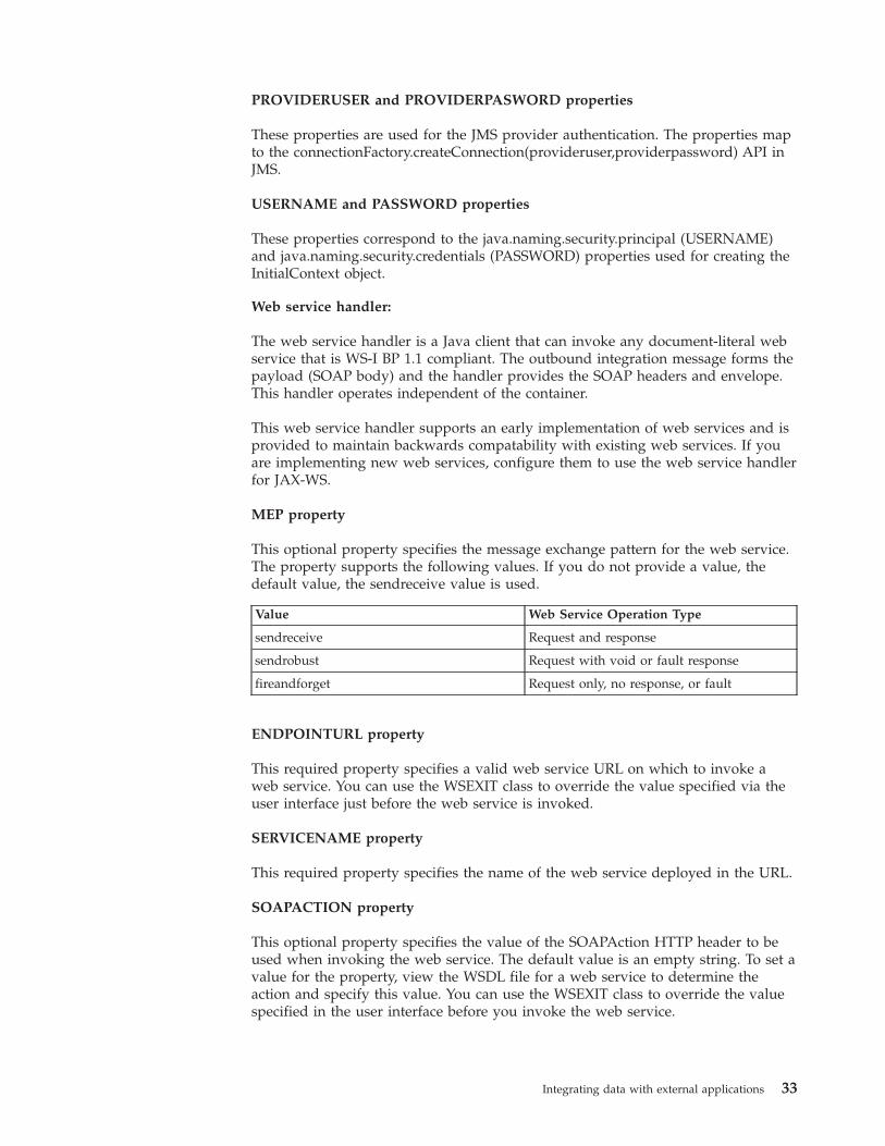
PROVIDERUSER and PROVIDERPASWORD properties
These properties are used for the JMS provider authentication. The properties mapto the connectionFactory.createConnection(provideruser,providerpassword) API inJMS.
USERNAME and PASSWORD properties
These properties correspond to the java.naming.security.principal (USERNAME)and java.naming.security.credentials (PASSWORD) properties used for creating theInitialContext object.
Web service handler:
The web service handler is a Java client that can invoke any document-literal webservice that is WS-I BP 1.1 compliant. The outbound integration message forms thepayload (SOAP body) and the handler provides the SOAP headers and envelope.This handler operates independent of the container.
This web service handler supports an early implementation of web services and isprovided to maintain backwards compatability with existing web services. If youare implementing new web services, configure them to use the web service handlerfor JAX-WS.
MEP property
This optional property specifies the message exchange pattern for the web service.The property supports the following values. If you do not provide a value, thedefault value, the sendreceive value is used.
Value Web Service Operation Type
sendreceive Request and response
sendrobust Request with void or fault response
fireandforget Request only, no response, or fault
ENDPOINTURL property
This required property specifies a valid web service URL on which to invoke aweb service. You can use the WSEXIT class to override the value specified via theuser interface just before the web service is invoked.
SERVICENAME property
This required property specifies the name of the web service deployed in the URL.
SOAPACTION property
This optional property specifies the value of the SOAPAction HTTP header to beused when invoking the web service. The default value is an empty string. To set avalue for the property, view the WSDL file for a web service to determine theaction and specify this value. You can use the WSEXIT class to override the valuespecified in the user interface before you invoke the web service.
Integrating data with external applications 33
SOAPVERSION property
This optional property specifies the version of the SOAP specification used duringweb service call. Valid values are SOAP11 and SOAP12.
HTTPVERSION property
This optional property specifies the version of the HTTP protocol for web serviceinvocations. The valid values are HTTP/1.0 and HTTP/1.1. If you do not provide avalue, the system uses the default value, HTTP/1.1.
HTTPCONNTIMEOUT property
This optional property specifies the connection timeout value in milliseconds. Thedefault value for this property is 60000 milliseconds.
HTTPREADTIMEOUT property
This optional property specifies the read timeout value in milliseconds. The defaultvalue for this property is 60000 milliseconds.
USERNAME and PASSWORD properties
If the specified web service is secured (if HTTP basic authentication is enabled),specify a user name and password.
WSEXIT property
In a multitenancy environment, customization by using Java classes can beimplemented only by the system provider and may not be supported in yourenvironment.
This optional property is used for customization. It specifies the fully qualifiedname of a custom Java class that implements the psdi.iface.router.WSExit interface.The property defines the following methods:
The responseOk() method is called after a successful invocation of the external webservice.public void responseError(Exception e) throws MXException
If an error occurs when the web service is called, the responseError() method iscalled with the originating exception as a parameter.
The default implementation of the WSExit interface ispsdi.iface.router.DefaultWSExit.
Web service handler (JAX-WS):
The WEBSERVICE-JAX-WS handler is a Java client that can invoke anydocument-literal web service that is WS-I BP 1.1 compliant. The outboundintegration message forms the payload (SOAP body) and the handler provides theSOAP headers and envelope.
This web service handler supports the current implementation of web services. Ifyou are implementing new web services, configure them to use this web servicehandler.
34 Integrating Data With External Applications
MEP property
This optional property specifies the message exchange pattern for the web service.The property supports the following values. If you do not provide a value, thedefault sendreceive value is used.
Value Web Service Operation Type
sendreceive Request and response
sendrobust Request with void or fault response
fireandforget Request only, no response, or fault
ENABLEAPPCONTEXT property
Set this property to 1 (true) when implementing support for WS-* policies.
ENDPOINTURL property
This required property specifies a valid web service URL on which to invoke aweb service. You can use the WSEXIT class to override the value specified via theuser interface just before the web service is invoked.
SERVICENAME property
This required property specifies the name of the target web service that thehandler invokes.
SOAPACTION property
This optional property specifies the value of the SOAPAction HTTP header to beused when invoking the web service. The default value is an empty string. To set avalue for the property, view the WSDL file for a web service to determine theaction and specify this value. You can use the WSEXIT class to override the valuespecified in the user interface before you invoke the web service.
SOAPVERSION property
This optional property specifies the version of the SOAP specification used duringweb service call. Valid values are SOAP11 and SOAP12.
HTTPCONNTIMEOUT property
This optional property specifies the connection timeout value in milliseconds. Thedefault value for this property is 60000 milliseconds.
HTTPREADTIMEOUT property
This optional property specifies the read timeout value in milliseconds. The defaultvalue for this property is 60000 milliseconds.
HTTPHEADER property
This optional property can add a comma-separated list of names and values to theheader section of HTTP messages. The list includes name and value information inthe format of Headername1:Headervalue1, Headername2:Headervalue2. If no value
Integrating data with external applications 35
is provided in the property, custom code can inject the values into the transactioncontext during invocation channel processing.
USERNAME and PASSWORD properties
If the specified web service is secured (if HTTP basic authentication is enabled),specify a user name and password.
WSEXIT property
In a multitenancy environment, customization by using Java classes can beimplemented only by the system provider and may not be supported in yourenvironment.
This optional property is used for customization. It specifies the fully qualifiedname of a custom Java class that implements the psdi.iface.router.WSExit interface.The property defines the following methods:
The responseOk() method is called after a successful invocation of the external webservice.public void responseError(Exception e) throws MXException
If an error occurs when the web service is called, the responseError() method iscalled with the originating exception as a parameter.
The default implementation of the WSExit interface ispsdi.iface.router.DefaultWSExit.
CFGXMLPATH property
This property is obsolete. Do not use it.
XML file handler:
The XML file handler is a Java component that writes an outbound integrationmessage into a file in XML format.
FILEDIR property
This optional property specifies where the handler creates the XML files. Thedefault value is mxe.int.globaldir/xmlfiles. The file location must be accessible bythe JMS CRON task for the outbound queue for publish channel messages. ForInvocation Channel messages, the file location must be accessible by any MaximoAsset Management servers where an invocation channel can be initiated.
PRETTYPRINT property
This required property specifies whether the handler formats the XML file. Thevalid values are 0 and 1. A value of 1 prompts the handler to pretty print formatthe xml file. Publish channel, invocation channel, and invocation API file nameshave the following formats:externalsystemname_publishchannelname_uniqueidentifier.xml
invocationchannelname_uniqueidentifier.xml
v externalsystemname is the identifier of the system (the value ofMAXEXTSYSTEM.EXTSYSNAME).
36 Integrating Data With External Applications
v publishchannelname is the name of the publish channel.v uniqueidentifier is a number based on current system time.
For example, the file name MX_MXASSETInterface_10971102668641398.xmlindicates that the file was generated to send data to the external system EXTSYS1.The file name also indicates that the file contains the MXASSETInterface publishchannel.
Command line handler:
The CMDLINE handler takes a command and an endpoint as input. TheCMDLINE handler uses the SSH protocol to run the command on the targetsystem and return the results.
A metadata parameter is passed during a system invocation when the handler iscalled. The parameter is a map that contains the name of the endpoint thatrepresents the target system. The caller can target any system at run time and passthe endpoint to the command handler. The caller uses whatever configuration theendpoint has at the time of the invocation.
CMDLINE handler properties
The CMDLINE handler has the following properties:v CMDTIMEOUT – The timeout value for command executionv CONNTIMEOUT – The timeout value for the connectionv USERNAME – The user name for the connectionv PASSWORD – The password for corresponding user namev HOST – The host name of target where command is runv PORTNO – The port number of target where the command is runv IGNORESETUPERR – A boolean value that indicates whether to ignore an error
running the setup commandv RETRYINTERVAL – The time to wait between retrying a commandv MAXRETRY – The number of attempts to run a command before returning an
exceptionv SSHEXIT – The Java exit class that can be implemented to customize processing
of the handler
Command data parameters
The data parameter is a byte array representation of an XML document. The dataparameter contains the following information:v The tags that correspond to the setup commandv The working directoryv The command to runv Any substitution parameters
Available tags
The following tags are available:v CLWORKINGDIR – A directory to change (cd) to on the remote system before
the command is run.
Integrating data with external applications 37
v CLSSETUPCMD – A setup command to be run before the main command. Usethis tag for any environmental setup that must occur on the remote systembefore the main command is issued.
v CLCMDPATTERN - A string that defines the pattern of the command to be run.The format of this pattern is similar to the java.text.MessageFormat class. Anexample is ls -l {0}, where {0} represents a parameter that is substituted.
v CLSUB0 - The value to substitute into positions that are marked by {0} in theCLCMDPATTERN.
v CLSUB1- The value to substitute into positions that are marked by {1} in theCLCMDPATTERN.
v CLSUBn - The value to substitute into positions that are marked by {n} in theCLCMDPATTERN. A CLSUBn tag must correspond to each substitution positionin the CLCMDPATTERN tag.
Command results
The return byte array representation of an XML document contains the results ofthe command. The XML document contains tags that correspond to the returnvalue, STDOUT and STDERR.
The following tags are available:v CLRETURNCODE – The return code from the remote command.v CLRESPONSEOUT – The data that is returned by the remote command in
STDOUT tag.v CLRESPONSEERR – The data that is returned by the remote command in
STDERR tag.
Integration web servicesExternal systems can use integration framework web services to send messages orqueries to the Maximo database. You can use an integration framework service asthe source for a web service and then deploy this service to communicate withexternal systems.
Web service sourcesThe source of a web service can be an object structure service, a standard service,or an enterprise service.
Object structure services
You can create an object structure web service from a predefined or a user-definedobject structure service. Object structure web services support create, update,delete, sync, and query operations. Create and query operations also supportresponses. The response to the create operation can be based on the primary oralternate key of the primary object that is defined in the object structure. Theresponse to the query operation is provided in the XML schema format of theobject structure.
Standard services
You can create a standard web service from methods that are annotated inapplication services. To use methods as web services, annotated methods, such asthe ChangeStatus method, must exist within an application. A single standard webservice is created for each application service and all annotated methods within theservice are the web service operations. The input and output parameters of the
38 Integrating Data With External Applications
methods are associated with the input and output parameters for the standard webservice.
Enterprise services
You can create an enterprise web service from a predefined or a user-definedenterprise service. Enterprise web services support additional exit processing,business rules, and transformations. A service exists for each operation that iscontained in an enterprise service record (one service per operation). With the exitprocessing layer, you can map an external schema XML to the object structureXML for both the invocation and the response. Enterprise web services provideresponse content for the create and query operations that are processed in thequeue. The enterprise service definition has a ProcessResponse flag that indicateswhether the service supports a response.
JMS queue settings for enterprise web services:
Enterprise web services can use the Java Message Service (JMS) queue to processXML messages, or you can specify that the service bypasses the JMS queue.
JMS queue-based processing provides asynchronous message processing. Forenterprise services that support synchronous processes, you must specifynon-queue-based message processing. The integration framework processes XMLmessages from external applications based on the queue settings that are definedfor the enterprise web service:
Queue-based message processingA queue-based enterprise web service processes XML messages and writesthese messages into the configured, inbound JMS queue. When themessage is moved into the JMS queue, the external application is releasedfrom the invocation. The integration framework processes the messagesand saves them in the Maximo database.
An enterprise web service cannot use the JMS queue if the service includescreate or query operations that require a response to the externalapplication.
Non-queue-based message processingA non-queue-based enterprise web service processes messages from theintegration framework to the object processing layer and saves information,when applicable, to the Maximo database. After the enterprise web servicecompletes message processing, the integration framework sends a responseto the external application. You must specify non-queue-based processing ifthe enterprise web service supports query or create operations that requirea response to the external application.
Web service deployment optionsAfter you create a web service, you have a choice of deployment options. If youdeploy a web service to the product web service container, the deployment isautomatic. If you deploy a web service to an application server web servicecontainer, the deployment is manual.
You can deploy web services to one container type only. You cannot deploy someweb services to a product web service container and deploy other web services toan application server web service container. Deployment to the web servicecontainer for the product is the quicker option, because the deployment isautomatic. This type of deployment does not require redeployment of the MaximoEAR files or a restart of the application server.
Integrating data with external applications 39
To invoke a web service on the application server, you must deploy the service tothe application server web service container. Integration with an application servercan provide a web service with access to additional services, such as enhancedsecurity policies. If you choose this type of deployment, the information is addedto the deplmodule.dar file. You must then add this file to the application serverdeployment directory, rebuild the EAR files, and restart the application server.
You can convert existing web services that are deployed to the product web servicecontainer to redeploy them to the application server web service container.
Web service deployment actionsWhen you deploy a web service, a number of events occur, including thegeneration of the XML schema and the web services description language (WSDL)file for the web service.
When you deploy a web service, the following events occur:v The XML schema is made available for a new web service or the schema is
regenerated for an existing web service.v The WSDL file is made available for the service interface.v The web service is deployed for the selected service.v If Universal Description Discovery and Integration (UDDI) registry properties
are configured, the web service is registered in the UDDI registry.
The deployed web service is available at the following URL:http://hostname:port/meaweb/services/web service name
v host:port/meaweb is the value of the integration web application URL property.v web service name is the name of the service for which the web service is
deployed.
The list of deployed web services is available in the Web Services Libraryapplication.
Schema generationYou can generate the schema and view the XML for any web service in the WebServices Library application. You can also regenerate the schema to ensure that theschema is updated to reflect any changes that you make to the service.
A web service data structure is based on its associated object structure (for objectstructure services and enterprise services) or method signature (for standard webservices). The web service data structure is provided in a standard XMLrepresentation, as a schema. This schema is used to create the WSDL file for theservice.
If you change the data structure that is associated with a web service, regeneratethe schema to update its schema and the WSDL file. The following changes to thedata dictionary change the object structure:v Adding new fields to a tablev Changing the type of a fieldv Dropping fields from a tablev Changing a field from optional to required
The XML does not contain fields that are marked for exclusion in the objectstructure.
40 Integrating Data With External Applications
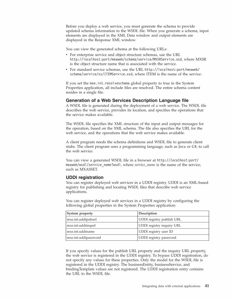
Before you deploy a web service, you must generate the schema to provideupdated schema information to the WSDL file. When you generate a schema, inputelements are displayed in the XML Data window and output elements aredisplayed in the Response XML window.
You can view the generated schema at the following URLs:v For enterprise service and object structure schemas, use the URL
http://localhost:port/meaweb/schema/service/MXSRService.xsd, where MXSRis the object structure name that is associated with the service.
v For standard service schemas, use the URL http://localhost:port/meaweb/schema/service/ss/ITEMService.xsd, where ITEM is the name of the service.
If you set the mxe.int.resolveschema global property to true in the SystemProperties application, all include files are resolved. The entire schema contentresides in a single file.
Generation of a Web Services Description Language fileA WSDL file is generated during the deployment of a web service. The WSDL filedescribes the web service, provides its location, and specifies the operations thatthe service makes available.
The WSDL file specifies the XML structure of the input and output messages forthe operation, based on the XML schema. The file also specifies the URL for theweb service, and the operations that the web service makes available.
A client program needs the schema definitions and WSDL file to generate clientstubs. The client program uses a programming language, such as Java or C#, to callthe web service.
You can view a generated WSDL file in a browser at http://localhost:port/meaweb/wsdl/service_name?wsdl, where service_name is the name of the service,such as MXASSET.
UDDI registrationYou can register deployed web services in a UDDI registry. UDDI is an XML-basedregistry for publishing and locating WSDL files that describe web serviceapplications.
You can register deployed web services in a UDDI registry by configuring thefollowing global properties in the System Properties application:
System property Description
mxe.int.uddipuburl UDDI registry publish URL
mxe.int.uddiinqurl UDDI registry inquiry URL
mxe.int.uddiname UDDI registry user ID
mxe.int.uddipassword UDDI registry password
If you specify values for the publish URL property and the inquiry URL property,the web service is registered in the UDDI registry. To bypass UDDI registration, donot specify any values for these properties. Only the model for the WSDL file isregistered in the UDDI registry. The businessEntity, businessService, andbindingTemplate values are not registered. The UDDI registration entry containsthe URL to the WSDL file.
Integrating data with external applications 41
Creating and deploying web servicesYou can create a web service based on any object structure service, standardservice, or enterprise service that is defined for the system. You then deploy theweb service to the product web service container or to the application web servicecontainer.
Creating a web service:
When you create a web service, an external system can send web-based messagesand queries to the associated service without configuring additionalcommunication protocols or services.
Before you begin
Perform the following checks to ensure that the service you want to use isavailable to create a web service:v For an object structure service, verify that the Consumed By field is set to
INTEGRATION in the Object Structures application.v For a standard service, ensure that a method is annotated in the application
service for each operation that you want to use in the web service. Only thosemethods that are properly annotated are accessible in the Web Services Libraryapplication
v For an enterprise service, ensure that the service is associated with an externalapplication in the External Systems application.
Procedure
1. In the Web Services Library application, select the appropriate Create WebService action.
2. Choose the service to use by selecting the corresponding Source Name checkbox.
3. Optional: In the Name field, specify an identifier for the web service.4. For a web service that is based on an enterprise service, specify whether you
want the web service to be queue-based or to bypass the JMS queue.5. Click Create.
What to do next
You must deploy the web service before you can use it to process inboundmessages and queries. You can also generate the schema and view the XMLstructures of any selected web service.
Deploying a web service to the product web service container:
After you create a web service, you must deploy it before it can start processingXML messages. When you deploy a web service to the product web servicecontainer, the deployment process occurs automatically and does not require aserver restart.
Procedure
1. In the Web Services Library application, select the web service that you want todeploy.
2. Select the Deploy to Product Web Service Container > Deploy Web Serviceaction.
42 Integrating Data With External Applications
3. Click OK.
Deploying a web service to the application server web service container:
A deployment file is generated when you deploy a web service to the applicationserver web service container. You must rebuild the Maximo EAR file to include thedeployment file and restart the application server to activate the web service.
About this task
The deplmodule.dar deployment file is in the directory that is specified by themxe.int.globaldir system property.
Procedure
1. In the Web Services Library application, select the web service that you want todeploy.
2. Select the Deploy to Application Server Web Service Container > GenerateDeployment File Entries action. This action generates an entry in thedeployment file, deplmodule.dar.
3. Click OK.4. Copy the deplmodule.dar file from the integration framework global directory
to the product deployment directory.5. In the deployment directory, run the buildmaximoear.cmd file.6. In the administrative console for the application server, deploy all web services
in the deplmodule.dar file:a. Stop the application server.b. Redeploy the maximo.ear file.c. Restart the application server.
Updating schema information:
If you change the data structure of an integration service, update the schemainformation to the WSDL file to update the web service. If you do not regeneratethe schema, the schema used by the web service can differ from the structuredefined for the associated integration service.
Procedure
1. After modifying the data structure of a web service, click Generate Schema,WSDL, and View XML. If you do not regenerate the schema, the web serviceis not aware of changes that you make.
2. For web services that are deployed to the application server web servicecontainer, you can automate schema updates in the System Propertiesapplication.a. Set the value of the mxe.int.containerdeploy property to 1 to deploy web
services to the application server web service container.b. Set the value of the mxe.int.wsdlincludeschema property to 1 to ensure that
schema information is included as part of WSDL files.c. Set the value of the mxe.int.resolveschema property to 1 to ensure that the
system resolves all included fields into a single file.d. Set the value of the mxe.int.wsdlcurrentschema property to 1 to provide
up-to-date schema content as part of a WSDL file.
Integrating data with external applications 43
Web service interactions overviewAn interaction can start a web service and send data to it from an application. Theinteraction can then display data returned from the web service and save this datato the application database.
To implement interactions requires knowledge of:v XML schemasv Web servicesv The integration frameworkv Customizing applications and application user interfaces
An interaction can manage the following processes:v Prepare a request for a web service.v Invoke a web service from an application.v Retrieve results from the web service in the form of a response.v Display the results in an application.v Optionally, apply the response data into the system database.v Report any errors that occur during the request or response processes.
Two applications are provided to help you create and manage interactions:v Create and configure interactions in the Create Interaction application.v Review, modify, and delete interactions in the Interactions application.
After you create an interaction, users can perform the following tasks from theapplication user interface:v Start the interaction.v View and, if configured, change the parameters of the request to the web service.v Invoke the web service by sending the request.v Optionally, view data received from the web service and commit this data to the
database.
Creating interactions:
The Create Interactions wizard application guides you through all the stepsrequired to create and configure an interaction. After you complete the wizardprocess and test the interaction, users can start working with it immediately withno requirement for additional configuration or deployment.
Before you begin
Before you run the Create Interactions application, ensure that you have all theinformation required for the configuration. During the process, you must specifythe web service, define the structure of messages, and map the data between theapplication and the web service.
A logging tool is provided to log configuration activity and maintain a log file ofthe items that are configured. To generate a detailed log of the configuration, in theLogging application, set the interaction logger to DEBUG mode.
44 Integrating Data With External Applications
Procedure
1. To configure the web service for the interaction, in step 1 of the process:a. Specify the URL for the WSDL file for the web service.b. When the screen refreshes with information from the WSDL file, specify one
port for the interaction.c. Specify one operation for the interaction and check Process Response if you
want the web service to return data to the application during theinteraction.
2. Review the contents of the request to the web service in step 2, and modify therequest object structure by removing any unnecessary elements.
3. Optional: Review the contents of the response from the web service in step 3,and modify the response object structure by removing any unnecessaryelements. This step is included only if you checked the Process Responseoption in step 1.
4. To configure the application for the interactions, in step 4 of the process:a. Specify the application that uses the interaction.b. Configure the application binding for the interaction, including the main
object, the signature option, the interaction mode, and the user interfacecomponents.
c. Specify the security groups that are authorized to initiate the interaction.5. Configure the Request tab of the Interactions window in step 5, including
specifying the fields that users can see and whether they can edit them.6. Optional: Configure the Response tab of the Interactions window in step 6,
including specifying the fields that users can see and whether they can editthem. This step is included only if you checked the Process Response option instep 1.
7. You can map information from the application to the web service in step 7.Mapped information is entered automatically into the request when users startthe interaction.
8. Optional: You can map information from the web service to the application instep 8. If you check the Commit Response option, the mapped information issaved automatically to the database.
9. Review the configurations in the final step of the process.
What to do next
To monitor the time it takes to execute the interaction, in the Logging application,set the integration logger to either INFO mode or DEBUG mode.
You can view the interaction and modify mapping information in the Interactionsapplication. If you intend to modify an interaction, select the DeactivateInteraction action before you make any changes and reactivate it after youcomplete the modification.
External systemsYou can configure the external system that the integration frameworkcommunicates with. You can configure external systems for external applicationswithin or outside your enterprise. If you copy a predefined external system, itcopies the channels and services that are configured for it. You can configure a newexternal system to use existing JMS queues.
Integrating data with external applications 45
Configuring an external systemTo configure an external system, identify the external system and associate it withthe channel or service used to process transactions. You must also configure theJMS queues that the external system uses and you can configure integrationcontrols to support customization with processing rules.
Creating an external system:
You create an external system to exchange data with external applications. Whenyou create an external system, the application copies the integration controls thatare defined for the corresponding publish channels and enterprise services. Youthen can specify default control values that apply to a particular external system.
Before you begin
Before you create an external system, define the queues and endpoint that theexternal system uses.
Procedure
1. In the External Systems application, click New External System.2. In the System field, specify an external system identifier.3. Optional: If the external system sends outbound messages, complete the
following steps:a. Specify a value in the Outbound Sequential Queue field.b. Specify a value in the End Point field.
4. Optional: If the external system receives inbound messages, complete thefollowing steps:a. Specify a value in the Inbound Sequential Queue field.b. Specify a value in the Inbound Continuous Queue field.
5. Click Save External System.
What to do next
You must enable at least one publish channel or enterprise service before messageprocessing can occur.
Enabling an external system:
You can enable an external system after you configure the external system recordand when you are ready to begin integration framework message processing. Youalso can disable an external system to stop all inbound and outbound messageprocessing.
Before you begin
You must enable at least one publish channel or enterprise service before anymessage processing can occur.
About this task
When you disable an external system, the integration framework does not acceptinbound messages or send outbound messages. Additionally, you cannot use theexternal system data export and data import features. Only messages that are inthe queues are processed.
46 Integrating Data With External Applications
Procedure
1. In the External Systems application, select the system that you want to update.2. Specify whether you want the external system to be enabled or disabled:
Option Enabled
Enabled Selected
Disabled Cleared
3. Click Save External System.
Enabling a publish channel:
You must enable a publish channel that is associated to an external system before itcan be used to publish event-based messages to an external system. By default, thepublish channel records that are associated with an external system are disabled. Adisabled publish channel prevents the external system from processing outboundintegration framework messages.
Procedure
1. In the External Systems application, select the system that you want to update.2. On the Publish Channels tab, specify whether you want the publish channel to
be enabled or disabled.
Option Enabled
Enabled Selected
Disabled Cleared
3. Click Save External System.
Associating a publish channel with an external system:
You can associate a publish channel with an external system to synchronize theasset management object data with the external application data. The channels thatyou create and associate to the external system contain the outbound messageprocessing logic.
About this task
You can define the endpoint that the channel uses. If you do not define anendpoint at the publish channel level, data is moved to the endpoint location thatis defined at the external system level. You also can enable the associated publishchannel when you are ready to perform outbound integration framework messageprocessing.
Procedure
1. In the External Systems application, select the external system that you want toupdate.
2. On the Publish Channels tab, click New Row.3. In the Publish Channel field, enter a value.4. Optional: In the End Point field, specify a value.5. Optional: Specify whether you want the publish channel to be enabled or
disabled:
Integrating data with external applications 47
Option Enabled
Enabled Selected
Disabled Cleared
6. Click Save External System.
Selecting publish channels for the external system:
You can associate multiple publish channels with an external system tosynchronize the asset management object data with the external application data.The channels that you create and associate to the external system contain theoutbound message processing logic.
Procedure
1. In the External Systems application, select the system that you want to update.2. On the Publish Channels tab, click Select Channel.3. Choose one or more publish channels by selecting the corresponding Publish
Channel check boxes.4. Click OK.5. Click Save External System.
What to do next
You can define the endpoints that the channels use. If you do not define anendpoint at the publish channel level, data is moved to the endpoint location thatis defined at the external system level. You must enable the associated publishchannels before you can perform integration framework message processing.
Adding an endpoint to a publish channel:
You can define the endpoint that a publish channel uses to determine where theoutbound data is published. Endpoints identify a target location and the transportmechanism for outbound data publication. If you do not define an endpoint at thepublish channel level, data is moved to the endpoint location that is defined at theexternal system level.
Before you begin
You must associate a publish channel to an external system.
Procedure
1. In the External Systems application, select the external system that you want toupdate.
2. On the Publish Channels tab, select the publish channel for which you want toadd an endpoint.
3. In the End Point field, specify a value.4. Click Save External System.
What to do next
You can enable the associated publish channel when you are ready to performoutbound integration framework message processing.
48 Integrating Data With External Applications
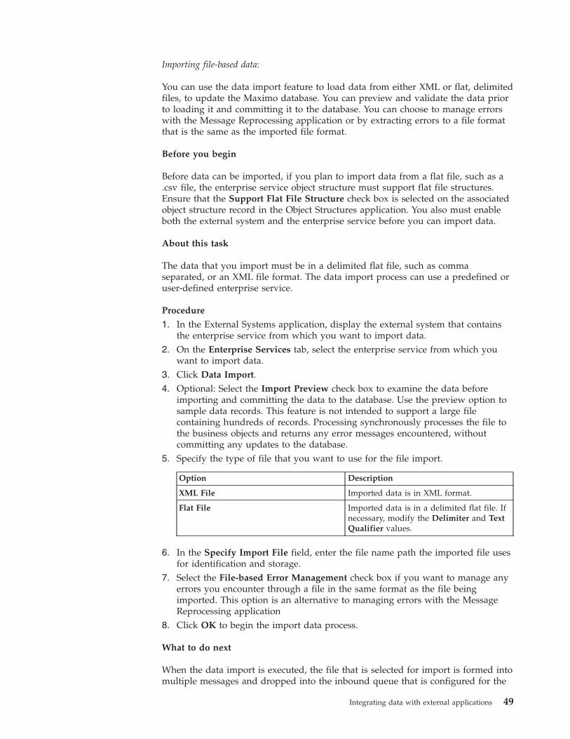
Importing file-based data:
You can use the data import feature to load data from either XML or flat, delimitedfiles, to update the Maximo database. You can preview and validate the data priorto loading it and committing it to the database. You can choose to manage errorswith the Message Reprocessing application or by extracting errors to a file formatthat is the same as the imported file format.
Before you begin
Before data can be imported, if you plan to import data from a flat file, such as a.csv file, the enterprise service object structure must support flat file structures.Ensure that the Support Flat File Structure check box is selected on the associatedobject structure record in the Object Structures application. You also must enableboth the external system and the enterprise service before you can import data.
About this task
The data that you import must be in a delimited flat file, such as commaseparated, or an XML file format. The data import process can use a predefined oruser-defined enterprise service.
Procedure
1. In the External Systems application, display the external system that containsthe enterprise service from which you want to import data.
2. On the Enterprise Services tab, select the enterprise service from which youwant to import data.
3. Click Data Import.4. Optional: Select the Import Preview check box to examine the data before
importing and committing the data to the database. Use the preview option tosample data records. This feature is not intended to support a large filecontaining hundreds of records. Processing synchronously processes the file tothe business objects and returns any error messages encountered, withoutcommitting any updates to the database.
5. Specify the type of file that you want to use for the file import.
Option Description
XML File Imported data is in XML format.
Flat File Imported data is in a delimited flat file. Ifnecessary, modify the Delimiter and TextQualifier values.
6. In the Specify Import File field, enter the file name path the imported file usesfor identification and storage.
7. Select the File-based Error Management check box if you want to manage anyerrors you encounter through a file in the same format as the file beingimported. This option is an alternative to managing errors with the MessageReprocessing application
8. Click OK to begin the import data process.
What to do next
When the data import is executed, the file that is selected for import is formed intomultiple messages and dropped into the inbound queue that is configured for the
Integrating data with external applications 49
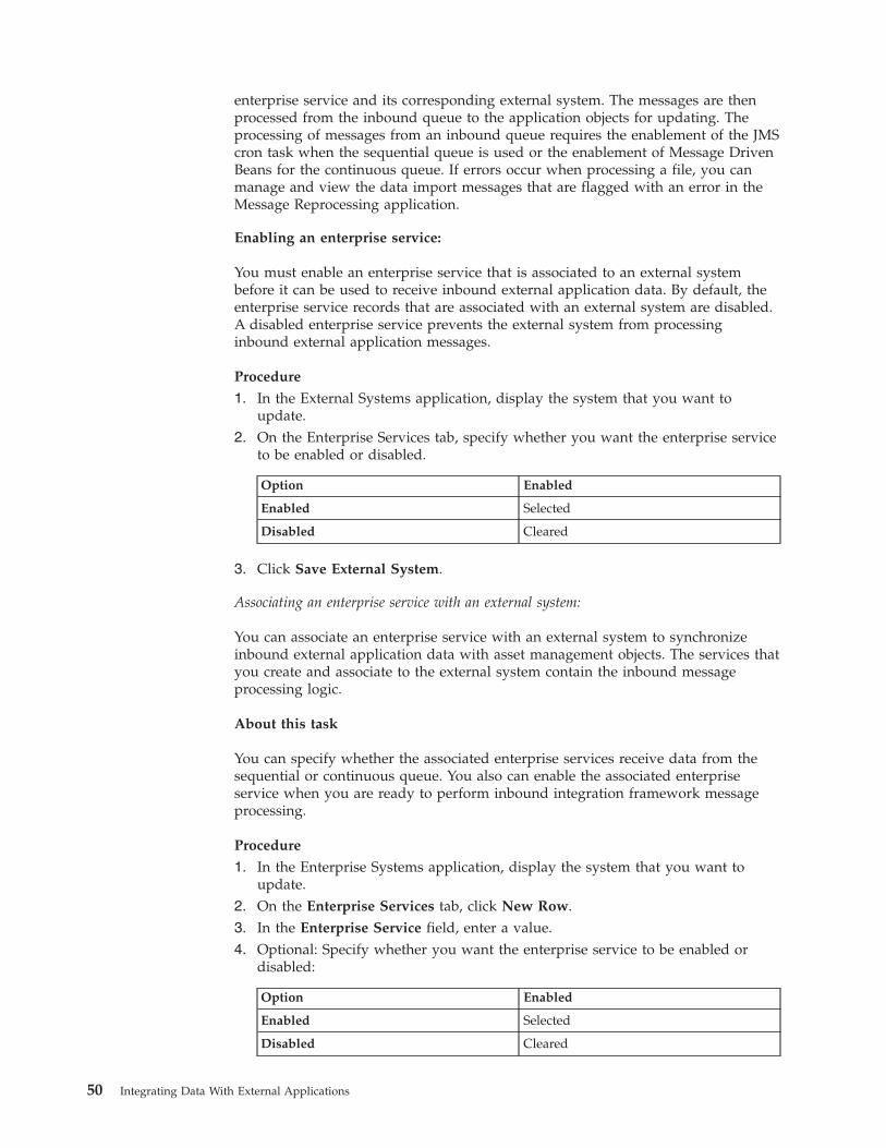
enterprise service and its corresponding external system. The messages are thenprocessed from the inbound queue to the application objects for updating. Theprocessing of messages from an inbound queue requires the enablement of the JMScron task when the sequential queue is used or the enablement of Message DrivenBeans for the continuous queue. If errors occur when processing a file, you canmanage and view the data import messages that are flagged with an error in theMessage Reprocessing application.
Enabling an enterprise service:
You must enable an enterprise service that is associated to an external systembefore it can be used to receive inbound external application data. By default, theenterprise service records that are associated with an external system are disabled.A disabled enterprise service prevents the external system from processinginbound external application messages.
Procedure
1. In the External Systems application, display the system that you want toupdate.
2. On the Enterprise Services tab, specify whether you want the enterprise serviceto be enabled or disabled.
Option Enabled
Enabled Selected
Disabled Cleared
3. Click Save External System.
Associating an enterprise service with an external system:
You can associate an enterprise service with an external system to synchronizeinbound external application data with asset management objects. The services thatyou create and associate to the external system contain the inbound messageprocessing logic.
About this task
You can specify whether the associated enterprise services receive data from thesequential or continuous queue. You also can enable the associated enterpriseservice when you are ready to perform inbound integration framework messageprocessing.
Procedure
1. In the Enterprise Systems application, display the system that you want toupdate.
2. On the Enterprise Services tab, click New Row.3. In the Enterprise Service field, enter a value.4. Optional: Specify whether you want the enterprise service to be enabled or
disabled:
Option Enabled
Enabled Selected
Disabled Cleared
50 Integrating Data With External Applications
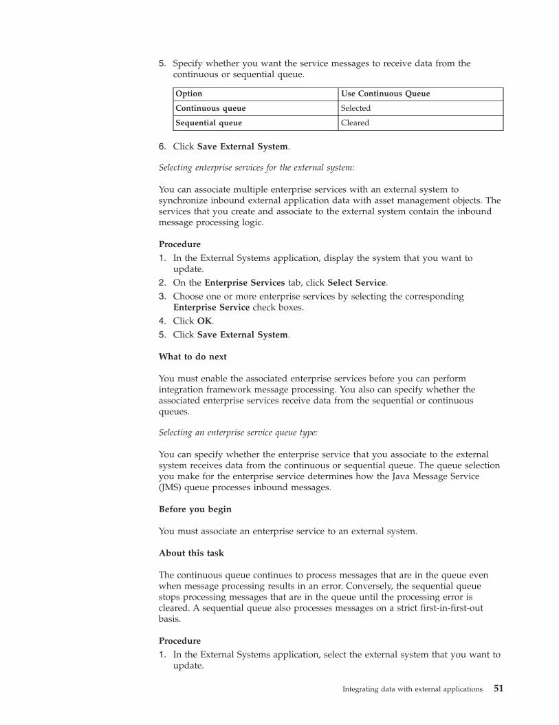
5. Specify whether you want the service messages to receive data from thecontinuous or sequential queue.
Option Use Continuous Queue
Continuous queue Selected
Sequential queue Cleared
6. Click Save External System.
Selecting enterprise services for the external system:
You can associate multiple enterprise services with an external system tosynchronize inbound external application data with asset management objects. Theservices that you create and associate to the external system contain the inboundmessage processing logic.
Procedure
1. In the External Systems application, display the system that you want toupdate.
2. On the Enterprise Services tab, click Select Service.3. Choose one or more enterprise services by selecting the corresponding
Enterprise Service check boxes.4. Click OK.5. Click Save External System.
What to do next
You must enable the associated enterprise services before you can performintegration framework message processing. You also can specify whether theassociated enterprise services receive data from the sequential or continuousqueues.
Selecting an enterprise service queue type:
You can specify whether the enterprise service that you associate to the externalsystem receives data from the continuous or sequential queue. The queue selectionyou make for the enterprise service determines how the Java Message Service(JMS) queue processes inbound messages.
Before you begin
You must associate an enterprise service to an external system.
About this task
The continuous queue continues to process messages that are in the queue evenwhen message processing results in an error. Conversely, the sequential queuestops processing messages that are in the queue until the processing error iscleared. A sequential queue also processes messages on a strict first-in-first-outbasis.
Procedure
1. In the External Systems application, select the external system that you want toupdate.
Integrating data with external applications 51
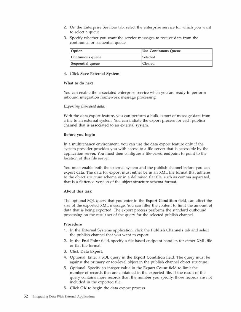
2. On the Enterprise Services tab, select the enterprise service for which you wantto select a queue.
3. Specify whether you want the service messages to receive data from thecontinuous or sequential queue.
Option Use Continuous Queue
Continuous queue Selected
Sequential queue Cleared
4. Click Save External System.
What to do next
You can enable the associated enterprise service when you are ready to performinbound integration framework message processing.
Exporting file-based data:
With the data export feature, you can perform a bulk export of message data froma file to an external system. You can initiate the export process for each publishchannel that is associated to an external system.
Before you begin
In a multitenancy environment, you can use the data export feature only if thesystem provider provides you with access to a file server that is accessible by theapplication server. You must then configure a file-based endpoint to point to thelocation of this file server.
You must enable both the external system and the publish channel before you canexport data. The data for export must either be in an XML file format that adheresto the object structure schema or in a delimited flat file, such as comma separated,that is a flattened version of the object structure schema format.
About this task
The optional SQL query that you enter in the Export Condition field, can affect thesize of the exported XML message. You can filter the content to limit the amount ofdata that is being exported. The export process performs the standard outboundprocessing on the result set of the query for the selected publish channel.
Procedure
1. In the External Systems application, click the Publish Channels tab and selectthe publish channel that you want to export.
2. In the End Point field, specify a file-based endpoint handler, for either XML fileor flat file format.
3. Click Data Export.4. Optional: Enter a SQL query in the Export Condition field. The query must be
against the primary or top-level object in the publish channel object structure.5. Optional: Specify an integer value in the Export Count field to limit the
number of records that are contained in the exported file. If the result of thequery contains more records than the number you specify, those records are notincluded in the exported file.
6. Click OK to begin the data export process.
52 Integrating Data With External Applications
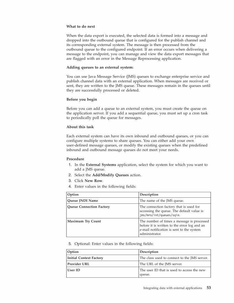
What to do next
When the data export is executed, the selected data is formed into a message anddropped into the outbound queue that is configured for the publish channel andits corresponding external system. The message is then processed from theoutbound queue to the configured endpoint. If an error occurs when delivering amessage to the endpoint, you can manage and view the data export messages thatare flagged with an error in the Message Reprocessing application.
Adding queues to an external system:
You can use Java Message Service (JMS) queues to exchange enterprise service andpublish channel data with an external application. When messages are received orsent, they are written to the JMS queue. These messages remain in the queues untilthey are successfully processed or deleted.
Before you begin
Before you can add a queue to an external system, you must create the queue onthe application server. If you add a sequential queue, you must set up a cron taskto periodically poll the queue for messages.
About this task
Each external system can have its own inbound and outbound queues, or you canconfigure multiple systems to share queues. You can either add your ownuser-defined message queues, or modify the existing queues when the predefinedinbound and outbound message queues do not meet your needs.
Procedure
1. In the External Systems application, select the system for which you want toadd a JMS queue.
2. Select the Add/Modify Queues action.3. Click New Row.4. Enter values in the following fields:
Option Description
Queue JNDI Name The name of the JMS queue.
Queue Connection Factory The connection factory that is used foraccessing the queue. The default value isjms/mro/int/queues/sqin.
Maximum Try Count The number of times a message is processedbefore it is written to the error log and ane-mail notification is sent to the systemadministrator.
5. Optional: Enter values in the following fields:
Option Description
Initial Context Factory The class used to connect to the JMS server.
Provider URL The URL of the JMS server.
User ID The user ID that is used to access the newqueue.
Integrating data with external applications 53
Option Description
Password The password that is use to access thequeue.
E-mail Address The e-mail address of a user who receivesnotices when transaction errors occur in thequeue. This value is typically the e-mailaddress of a system administrator.
6. Optional: If the queue delivers inbound messages and functions as acontinuous queue, clear the Sequential check box.
7. Optional: If the queue delivers outbound messages, clear the Inbound checkbox.
8. Click OK.9. On the System tab, enter values in the following fields:
v Outbound Sequential Queue
v Inbound Sequential Queue
v Inbound Continuous Queue
10. Click Save External System.
Creating interface tables:
You can create an interface table to integrate with external systems that usedatabase tables for data exchange. Interface tables reflect the content of publishchannel or enterprise service object structures. You must recreate existing tableswhen you change the definition of the corresponding object structure.
Before you begin
You cannot recreate an interface table when unprocessed messages for thatinterface table exist in the MXIN_INTER_TRANS queue table. If you do not backup data before you recreate an interface table, the system loses the data. Ensurethat alias conflicts are resolved and the Support Flat File Structure check boxes areselected on the associated object structure records in the Object Structuresapplication.
About this task
The Create Interface Table dialog box displays the interface tables that areassociated with publish channels and enterprise services that have the followingcharacteristics:v Registered to the selected external system.v Interface table name is not null.v Corresponding object structure supports a flat file representation.
Procedure
1. In the External Systems application, select the Create Interface Tables action.2. In the Create Interface Tables dialog box, select the interface table that you
want update and create.3. Enter a value in the End Point field.4. Optional: Select the Rename Existing check box to create a copy of the selected
interface table. The asset management system stores copy of the interface tableand adds a BAK suffix to its name.
54 Integrating Data With External Applications
5. Click Create.6. Click OK to create the table or Cancel to stop the process. Depending on the
number of interface tables you are creating, this process can take some time.7. Click OK to close the Create Interface Tables dialog box.
Working with integration controls:
If integration channels or services contain processing rules or exit classes that arebased on integration controls, the values of the integration controls can beconfigured for the external system. You can configure boolean, list, and valueintegration controls that you can incorporate in processing rules.
Setting up a Boolean control:
You can set up a Boolean control on an external system when you need a controlthat specifies a value of true or false. You also can add specific organization-leveland site-level values to a Boolean control. An enterprise service or a publishchannel can use this Boolean control in its processing rule evaluations. The true orfalse value that you assign to the control in the external system determineswhether an enterprise service or publish channel applies a processing rule.
Before you begin
The boolean value that you assign to a control must already exist in the controldefinition in the Publish Channels or Enterprise Services application. If thatdefinition points to a domain, any organization-level or site-level values that youassign must exist in that domain.
Procedure
1. In the External Systems application, display the system that you want toupdate.
2. Select the Set Up Integration Controls action.3. Select the boolean control that you want to update.4. Click New Row.5. Perform one of the following actions:
v Enter a value in the Organization field.v Enter a value in the Site field.
6. Specify whether you want the Boolean control to have a default value of trueor false.
Option Default True
True value Selected
False value Cleared
7. Click OK to close the Boolean Control dialog box.8. Click OK to close the Set Up Integration Controls dialog box.
Setting up a cross-reference control:
You can set up a cross-reference control when you need a control that replaces onevalue with another. A cross-reference control can map a value in the assetmanagement system to a value in the external system.
Integrating data with external applications 55
Before you begin
The value that you assign for translation must first exist in the control definition inthe Publish Channels or Enterprise Services application. If that definition points toa domain, the organization-level or site-level values that you assign must exist inthat domain.
Procedure
1. In the External Systems application, display the system that you want toupdate.
2. Select the Setup Integration Controls action.3. Select the cross-reference control that you want to update.4. Click New Row.5. In the Maximo Value field, enter the application value that the asset
management system converts to or from an external system value.6. In the External Value field, enter the external system value the asset
management system converts to or from the Maximo value.7. Click OK to close the Cross-Reference Control dialog box.8. Click OK to close the Setup Integration Controls dialog box.
Setting up a list control:
You create a list type integration control when you need a control that contains alist of values. You also can add specific organization-level and site-level values to alist control. An enterprise service or publish channel can use this list control in itsprocessing rule evaluations. The value that you assign to the control in the externalsystem determines whether an enterprise service or publish channel applies aprocessing rule.
Before you begin
The values that you add to a list control must already exist in the control definitionin the Publish Channels or Enterprise Services application. If that definition pointsto a domain, the organization-level or site-level values that you assign must existin that domain.
Procedure
1. In the External Systems application, display the system that you want toupdate.
2. Select the Set Up Integration Controls action.3. Select the list control that you want to update.4. Click New Row.5. In the Value field, enter a value that exists in the domain.6. Click OK to close the List Control dialog box.7. Click OK to close the Set Up Integration Controls dialog box.
Setting up a value control:
You can set a value type integration control on an external system when you needa control that contains a single value. You also can add specific organization-leveland site-level values to a value control. An enterprise service or a publish channelcan use this value control in its processing rule evaluations. The value that you
56 Integrating Data With External Applications
assign to the control in the external system determines whether an enterpriseservice or publish channel applies a processing rule.
Before you begin
The value that you assign first must exist in the control definition in the PublishChannels or Enterprise Services application. If that definition points to a domain,the organization-level or site-level values that you assign must exist in thatdomain.
Procedure
1. In the External Systems application, display the system that you want toupdate.
2. Select the Set Up Integration Controls action.3. Select the value control that you want to update.4. Click New Row.5. Perform one of the following actions:
v Enter a value in the Organization field.v Enter a value in the Site field.
6. In the Value field, enter a value that exists in the domain.7. Click OK to close the Value Control dialog box.8. Click OK to close the Set Up Integration Controls dialog box.
Overriding values for a cross-reference control:
You can set up a cross-reference control to override values for sites andorganizations. You can choose to override the cross-reference values that werepreviously defined at the enterprise service or publish channel level. The valueoverride can be configured according to each external system to maintain validasset management system and external system mappings.
Before you begin
The value that you use for translation must first exist in the cross-reference controldefinition in the Publish Channels or Enterprise Services application. If thatdefinition points to a domain, the organization-level or site-level values that youassign must exist in that domain.
About this task
If you use synonyms, enter the external value as the control value, not the internalapplication value.
Procedure
1. In the External Systems application, display the system that you want toupdate.
2. Select the Setup Integration Controls action.3. Select the cross-reference control that you want to update.4. Click Override. The Override Values for Cross-Reference Control dialog boxh
displays any organization-level and site-level values that exist for the control.5. Click New Row.6. Perform one of the following actions:
Integrating data with external applications 57
v Enter a value in the Organization field.v Enter a value in the Site field.
7. In the Values for Organization/Site table window, click New Row.8. Enter the values in the Default Value and External Value fields. To use the
control as a multiplication control, enter multiple records that have the sameexternal value and different organization or site values.
9. Click OK to close the Override Values for Cross-Reference Control dialog box.10. Click OK to close the Cross-Reference Control dialog box .11. Click OK to close the Set Up Integration Controls dialog box .
Example
Five external systems are configured to exchange data with the integrationframework. Four of these external systems use the same site values, but one sitevalue differs. A cross-reference control that performs the translation between thefour mismatched values and the asset management system value can beoverwritten at an external system level. The value override can be configured totranslate the remaining mismatched external system site value to an assetmanagement system storeroom value.
A cross-reference control in an enterprise service can translate the external systemsite value EX001 to an asset management system site MX001. An overridecross-reference control in external system can override the predefined EX001 valueand use an EX002 value in its value translation.
Overriding values for a list control:
You can set up a list control to override values for sites and organizations. You canchoose to override the list control values that were previously defined in theenterprise service or publish channel level. The rule could skip the processing ofthe transaction when the data field value does not match any of the overwrittenlist control values.
Before you begin
The value that you assign first must exist in the control definition in the PublishChannels or Enterprise Services application. If that definition points to a domain,the organization-level or site-level values that you assign must exist in thatdomain.
About this task
You must use a period (.) as the decimal placeholder when you enter decimals as acontrol value, regardless of the locale settings of the application server or database.Numbers to the left of the placeholder are not formatted. This format applies toinbound and outbound data. For example, $1,738,593.64 must be 1738593.64.
Procedure
1. In the External Systems application, display the system that you want toupdate.
2. Select the Set Up Integration Controls action.3. Select the list control that you want to update.4. Click Override. The Override Values for List Control dialog box displays any
organization-level and site-level values that exist for the control.
58 Integrating Data With External Applications
5. Click New Row.6. Perform one of the following actions:
v Enter a value in the Organization field.v Enter a value in the Site field.
7. In the Values for Organization/Site table window, click New Row.8. Enter a value in the Value field. If you use synonyms, enter an external value,
not the internal application value.9. Click OK to close the Override Values for List Control dialog box.
10. Click OK to close the Cross-Reference Control dialog box .11. Click OK to close the Set Up Integration Controls dialog box .
Example
Work orders are sent to an external system based on their statuses. The processingrule that is defined on an enterprise service or publish channel can check the statusof a work order against a list control that contains two status values: APPR(approved) or COMPLETE. This list override can be configured to evaluate twodifferent work order status values: WAPPR (waiting on approval) or WSCH (waitingto be scheduled). If the status of a work order does not match the overwritten listcontrol values, the work order transaction is not sent to the external system.
Predefined integration contentThe integration framework provides predefined integration content, includingobject structures, publish channels and enterprise services that support importingdata from external system or exporting data to them.
In some cases, only the object structure is provided without a related publishchannel or enterprise service. The integration framework, by design, providessupport for inserting, updating, deleting and querying data according the businessrules defined in the business objects within the object structure. It does not provideall the functionality that is available through the applications, including those thatare available from actions or the processing button on the screen. Some objectstructures may provide support for some actions or the processing button on thescreen.
Master data objectsThe integration framework provides a selection of predefined integration contentfor master data, which generally consists of accounting, people, storeroom, labor,classification, and vendor data.
Asset object:
The MXASSET object structure allows for bidirectional synchronization of assetinformation, including attributes that define meters.
Purpose
The MXASSET object structure synchronizes individual assets, but not the assethierarchy as a whole. It supports the addition and update of meters tied to anasset, but not the update of meter reading values. Inbound processing ofASSETMETER is restricted to attributes that define the meter, not meter readingvalues or other information pertaining to meter readings.
Integrating data with external applications 59
Prerequisite
You must synchronize applicable operating locations, storerooms, meters, anditems before loading assets.
The MBO relationship used to retrieve the ASSETMETER MBO is different fromthe MBO relationship used in the Assets application. Therefore, the changedattribute in the XML (outbound processing) is not set for any values from thisMBO.
This object structure does not support status changes or asset movement. Astandard service for assets is provided to support moving assets that reside inoperating locations. The standard service, Asset, provides an operation,assetmoveSingleAsset, to support this functionality.
Outbound Integration Processing
The following table shows the predefined values used in outbound integrationprocessing.
Predefined integration components Value and description
Object Structure definition class functionality MoutAssetProcess - Populates theHierarchypath field if a classification isassociated with the asset.
Publish Channel MXASSETInterface
Processing Rules None
Integration Controls None
Inbound Integration Processing
The following table shows the preconfigured values used in inbound integrationprocessing.
Predefined integration components Value and description
Object Structure processing classfunctionality
MaxAssetProcess - If the Hierarchypath isprovided, the processing class populates thecorresponding classstructureid field of theasset, which creates the association of theclassification with the asset.
Enterprise Service MXASSETInterface
Processing Rules None
Integration Controls None
Chart of Account object:
The MXCOA object structure allows for inbound synchronization of chart ofaccounts data.
Prerequisite
You must load general ledger components before loading the chart of accounts.There is no predefined publish channel for this object structure.
60 Integrating Data With External Applications
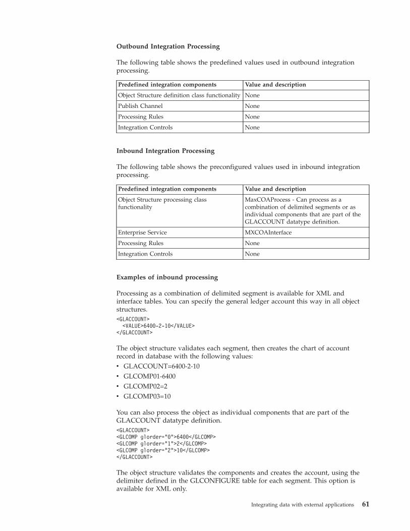
Outbound Integration Processing
The following table shows the predefined values used in outbound integrationprocessing.
Predefined integration components Value and description
Object Structure definition class functionality None
Publish Channel None
Processing Rules None
Integration Controls None
Inbound Integration Processing
The following table shows the preconfigured values used in inbound integrationprocessing.
Predefined integration components Value and description
Object Structure processing classfunctionality
MaxCOAProcess - Can process as acombination of delimited segments or asindividual components that are part of theGLACCOUNT datatype definition.
Enterprise Service MXCOAInterface
Processing Rules None
Integration Controls None
Examples of inbound processing
Processing as a combination of delimited segment is available for XML andinterface tables. You can specify the general ledger account this way in all objectstructures.<GLACCOUNT>
<VALUE>6400-2-10</VALUE></GLACCOUNT>
The object structure validates each segment, then creates the chart of accountrecord in database with the following values:v GLACCOUNT=6400-2-10v GLCOMP01-6400v GLCOMP02=2v GLCOMP03=10
You can also process the object as individual components that are part of theGLACCOUNT datatype definition.<GLACCOUNT><GLCOMP glorder="0">6400</GLCOMP><GLCOMP glorder="1">2</GLCOMP><GLCOMP glorder="2">10</GLCOMP></GLACCOUNT>
The object structure validates the components and creates the account, using thedelimiter defined in the GLCONFIGURE table for each segment. This option isavailable for XML only.
Integrating data with external applications 61
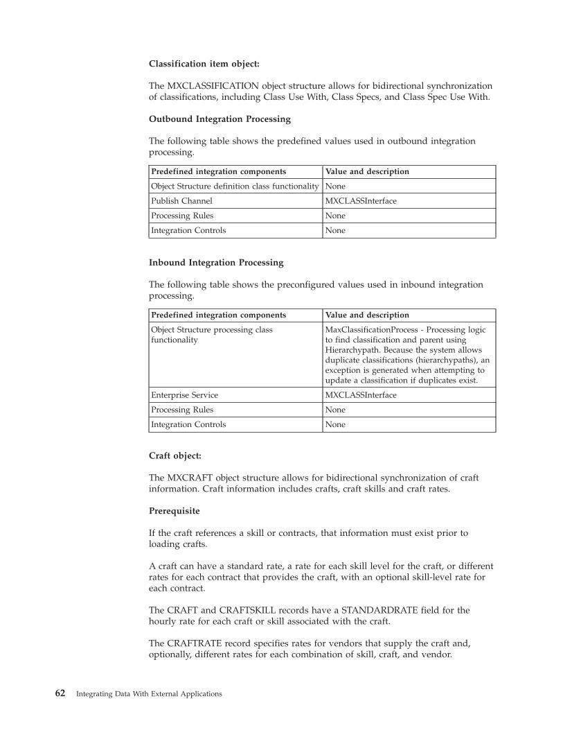
Classification item object:
The MXCLASSIFICATION object structure allows for bidirectional synchronizationof classifications, including Class Use With, Class Specs, and Class Spec Use With.
Outbound Integration Processing
The following table shows the predefined values used in outbound integrationprocessing.
Predefined integration components Value and description
Object Structure definition class functionality None
Publish Channel MXCLASSInterface
Processing Rules None
Integration Controls None
Inbound Integration Processing
The following table shows the preconfigured values used in inbound integrationprocessing.
Predefined integration components Value and description
Object Structure processing classfunctionality
MaxClassificationProcess - Processing logicto find classification and parent usingHierarchypath. Because the system allowsduplicate classifications (hierarchypaths), anexception is generated when attempting toupdate a classification if duplicates exist.
Enterprise Service MXCLASSInterface
Processing Rules None
Integration Controls None
Craft object:
The MXCRAFT object structure allows for bidirectional synchronization of craftinformation. Craft information includes crafts, craft skills and craft rates.
Prerequisite
If the craft references a skill or contracts, that information must exist prior toloading crafts.
A craft can have a standard rate, a rate for each skill level for the craft, or differentrates for each contract that provides the craft, with an optional skill-level rate foreach contract.
The CRAFT and CRAFTSKILL records have a STANDARDRATE field for thehourly rate for each craft or skill associated with the craft.
The CRAFTRATE record specifies rates for vendors that supply the craft and,optionally, different rates for each combination of skill, craft, and vendor.
62 Integrating Data With External Applications
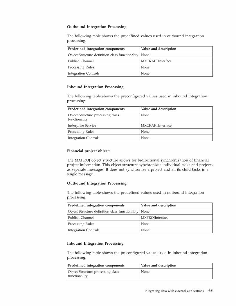
Outbound Integration Processing
The following table shows the predefined values used in outbound integrationprocessing.
Predefined integration components Value and description
Object Structure definition class functionality None
Publish Channel MXCRAFTInterface
Processing Rules None
Integration Controls None
Inbound Integration Processing
The following table shows the preconfigured values used in inbound integrationprocessing.
Predefined integration components Value and description
Object Structure processing classfunctionality
None
Enterprise Service MXCRAFTInterface
Processing Rules None
Integration Controls None
Financial project object:
The MXPROJ object structure allows for bidirectional synchronization of financialproject information. This object structure synchronizes individual tasks and projectsas separate messages. It does not synchronize a project and all its child tasks in asingle message.
Outbound Integration Processing
The following table shows the predefined values used in outbound integrationprocessing.
Predefined integration components Value and description
Object Structure definition class functionality None
Publish Channel MXPROJInterface
Processing Rules None
Integration Controls None
Inbound Integration Processing
The following table shows the preconfigured values used in inbound integrationprocessing.
Predefined integration components Value and description
Object Structure processing classfunctionality
None
Integrating data with external applications 63
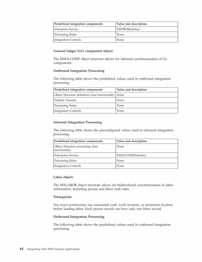
Predefined integration components Value and description
Enterprise Service MXPROJInterface
Processing Rules None
Integration Controls None
General ledger (GL) component object:
The MXGLCOMP object structure allows for inbound synchronization of GLcomponents.
Outbound Integration Processing
The following table shows the predefined values used in outbound integrationprocessing.
Predefined integration components Value and description
Object Structure definition class functionality None
Publish Channel None
Processing Rules None
Integration Controls None
Inbound Integration Processing
The following table shows the preconfigured values used in inbound integrationprocessing.
Predefined integration components Value and description
Object Structure processing classfunctionality
None
Enterprise Service MXGLCOMPInterface
Processing Rules None
Integration Controls None
Labor object:
The MXLABOR object structure allows for bidirectional synchronization of laborinformation, including person and labor craft rates.
Prerequisite
You must synchronize any associated craft, work location, or storeroom locationbefore loading labor. Each person record can have only one labor record.
Outbound Integration Processing
The following table shows the predefined values used in outbound integrationprocessing.
64 Integrating Data With External Applications
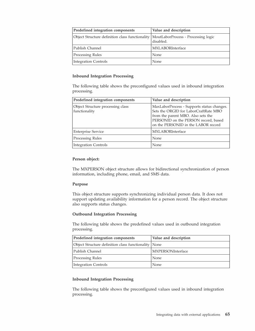
Predefined integration components Value and description
Object Structure definition class functionality MoutLaborProcess - Processing logicdisabled.
Publish Channel MXLABORInterface
Processing Rules None
Integration Controls None
Inbound Integration Processing
The following table shows the preconfigured values used in inbound integrationprocessing.
Predefined integration components Value and description
Object Structure processing classfunctionality
MaxLaborProcess - Supports status changes.Sets the ORGID for LaborCraftRate MBOfrom the parent MBO. Also sets thePERSONID on the PERSON record, basedon the PERSONID in the LABOR record
Enterprise Service MXLABORInterface
Processing Rules None
Integration Controls None
Person object:
The MXPERSON object structure allows for bidirectional synchronization of personinformation, including phone, email, and SMS data.
Purpose
This object structure supports synchronizing individual person data. It does notsupport updating availability information for a person record. The object structurealso supports status changes.
Outbound Integration Processing
The following table shows the predefined values used in outbound integrationprocessing.
Predefined integration components Value and description
Object Structure definition class functionality None
Publish Channel MXPERSONInterface
Processing Rules None
Integration Controls None
Inbound Integration Processing
The following table shows the preconfigured values used in inbound integrationprocessing.
Integrating data with external applications 65
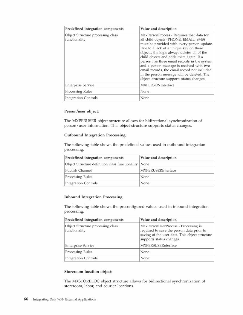
Predefined integration components Value and description
Object Structure processing classfunctionality
MaxPersonProcess - Requires that data forall child objects (PHONE, EMAIL, SMS)must be provided with every person update.Due to a lack of a unique key on theseobjects, the logic always deletes all of thechild objects and adds them again. If aperson has three email records in the systemand a person message is received with twoemail records, the email record not includedin the person message will be deleted. Theobject structure supports status changes.
Enterprise Service MXPERSONInterface
Processing Rules None
Integration Controls None
Person/user object:
The MXPERUSER object structure allows for bidirectional synchronization ofperson/user information. This object structure supports status changes.
Outbound Integration Processing
The following table shows the predefined values used in outbound integrationprocessing.
Predefined integration components Value and description
Object Structure definition class functionality None
Publish Channel MXPERUSERInterface
Processing Rules None
Integration Controls None
Inbound Integration Processing
The following table shows the preconfigured values used in inbound integrationprocessing.
Predefined integration components Value and description
Object Structure processing classfunctionality
MaxPersonUserProcess - Processing isrequired to save the person data prior tosaving of the user data. This object structuresupports status changes.
Enterprise Service MXPERSUSERnterface
Processing Rules None
Integration Controls None
Storeroom location object:
The MXSTORELOC object structure allows for bidirectional synchronization ofstoreroom, labor, and courier locations.
66 Integrating Data With External Applications
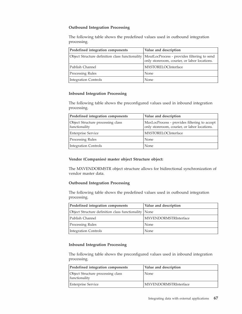
Outbound Integration Processing
The following table shows the predefined values used in outbound integrationprocessing.
Predefined integration components Value and description
Object Structure definition class functionality MoutLocProcess - provides filtering to sendonly storeroom, courier, or labor locations.
Publish Channel MXSTORELOCInterface
Processing Rules None
Integration Controls None
Inbound Integration Processing
The following table shows the preconfigured values used in inbound integrationprocessing.
Predefined integration components Value and description
Object Structure processing classfunctionality
MaxLocProcess - provides filtering to acceptonly storeroom, courier, or labor locations.
Enterprise Service MXSTORELOCInterface
Processing Rules None
Integration Controls None
Vendor (Companies) master object Structure object:
The MXVENDORMSTR object structure allows for bidirectional synchronization ofvendor master data.
Outbound Integration Processing
The following table shows the predefined values used in outbound integrationprocessing.
Predefined integration components Value and description
Object Structure definition class functionality None
Publish Channel MXVENDORMSTRInterface
Processing Rules None
Integration Controls None
Inbound Integration Processing
The following table shows the preconfigured values used in inbound integrationprocessing.
Predefined integration components Value and description
Object Structure processing classfunctionality
None
Enterprise Service MXVENDORMSTRInterface
Integrating data with external applications 67
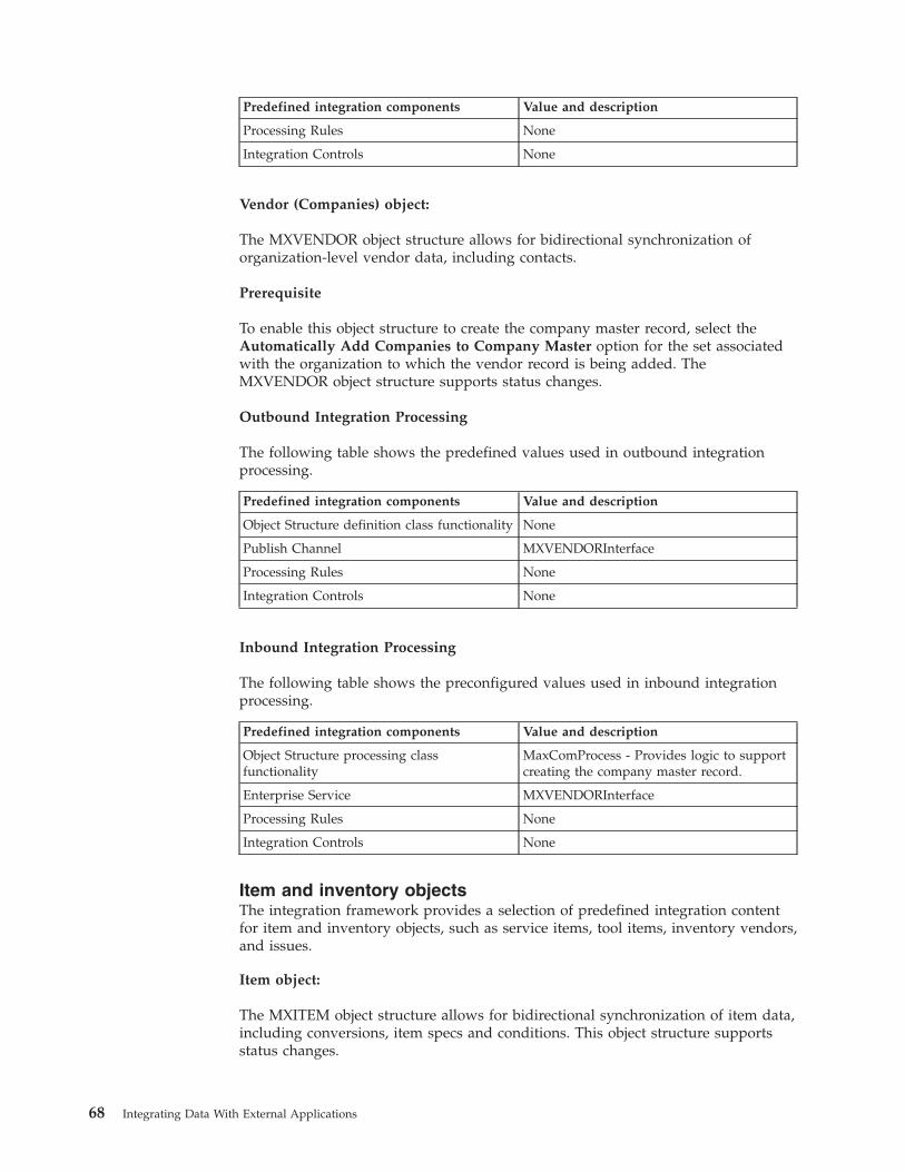
Predefined integration components Value and description
Processing Rules None
Integration Controls None
Vendor (Companies) object:
The MXVENDOR object structure allows for bidirectional synchronization oforganization-level vendor data, including contacts.
Prerequisite
To enable this object structure to create the company master record, select theAutomatically Add Companies to Company Master option for the set associatedwith the organization to which the vendor record is being added. TheMXVENDOR object structure supports status changes.
Outbound Integration Processing
The following table shows the predefined values used in outbound integrationprocessing.
Predefined integration components Value and description
Object Structure definition class functionality None
Publish Channel MXVENDORInterface
Processing Rules None
Integration Controls None
Inbound Integration Processing
The following table shows the preconfigured values used in inbound integrationprocessing.
Predefined integration components Value and description
Object Structure processing classfunctionality
MaxComProcess - Provides logic to supportcreating the company master record.
Enterprise Service MXVENDORInterface
Processing Rules None
Integration Controls None
Item and inventory objectsThe integration framework provides a selection of predefined integration contentfor item and inventory objects, such as service items, tool items, inventory vendors,and issues.
Item object:
The MXITEM object structure allows for bidirectional synchronization of item data,including conversions, item specs and conditions. This object structure supportsstatus changes.
68 Integrating Data With External Applications
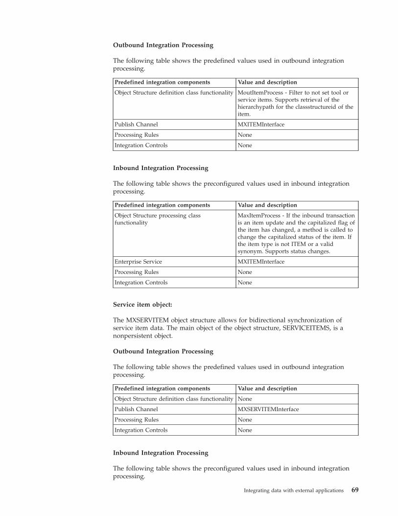
Outbound Integration Processing
The following table shows the predefined values used in outbound integrationprocessing.
Predefined integration components Value and description
Object Structure definition class functionality MoutItemProcess - Filter to not set tool orservice items. Supports retrieval of thehierarchypath for the classstructureid of theitem.
Publish Channel MXITEMInterface
Processing Rules None
Integration Controls None
Inbound Integration Processing
The following table shows the preconfigured values used in inbound integrationprocessing.
Predefined integration components Value and description
Object Structure processing classfunctionality
MaxItemProcess - If the inbound transactionis an item update and the capitalized flag ofthe item has changed, a method is called tochange the capitalized status of the item. Ifthe item type is not ITEM or a validsynonym. Supports status changes.
Enterprise Service MXITEMInterface
Processing Rules None
Integration Controls None
Service item object:
The MXSERVITEM object structure allows for bidirectional synchronization ofservice item data. The main object of the object structure, SERVICEITEMS, is anonpersistent object.
Outbound Integration Processing
The following table shows the predefined values used in outbound integrationprocessing.
Predefined integration components Value and description
Object Structure definition class functionality None
Publish Channel MXSERVITEMInterface
Processing Rules None
Integration Controls None
Inbound Integration Processing
The following table shows the preconfigured values used in inbound integrationprocessing.
Integrating data with external applications 69
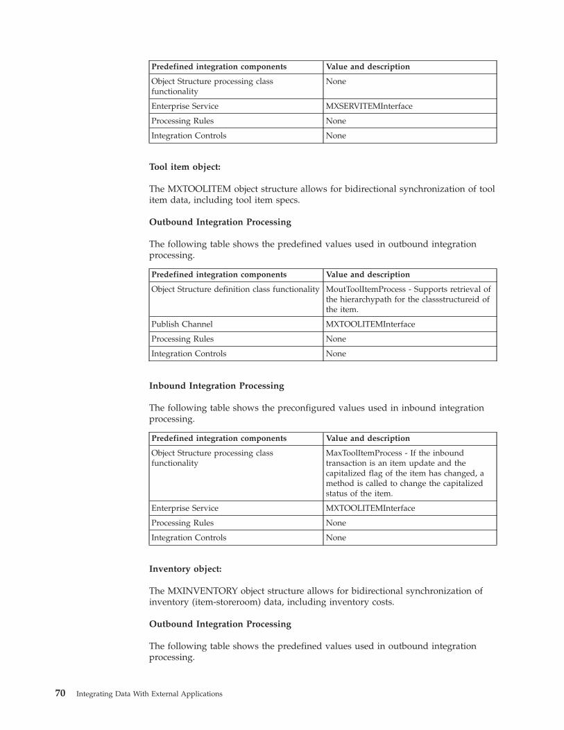
Predefined integration components Value and description
Object Structure processing classfunctionality
None
Enterprise Service MXSERVITEMInterface
Processing Rules None
Integration Controls None
Tool item object:
The MXTOOLITEM object structure allows for bidirectional synchronization of toolitem data, including tool item specs.
Outbound Integration Processing
The following table shows the predefined values used in outbound integrationprocessing.
Predefined integration components Value and description
Object Structure definition class functionality MoutToolItemProcess - Supports retrieval ofthe hierarchypath for the classstructureid ofthe item.
Publish Channel MXTOOLITEMInterface
Processing Rules None
Integration Controls None
Inbound Integration Processing
The following table shows the preconfigured values used in inbound integrationprocessing.
Predefined integration components Value and description
Object Structure processing classfunctionality
MaxToolItemProcess - If the inboundtransaction is an item update and thecapitalized flag of the item has changed, amethod is called to change the capitalizedstatus of the item.
Enterprise Service MXTOOLITEMInterface
Processing Rules None
Integration Controls None
Inventory object:
The MXINVENTORY object structure allows for bidirectional synchronization ofinventory (item-storeroom) data, including inventory costs.
Outbound Integration Processing
The following table shows the predefined values used in outbound integrationprocessing.
70 Integrating Data With External Applications
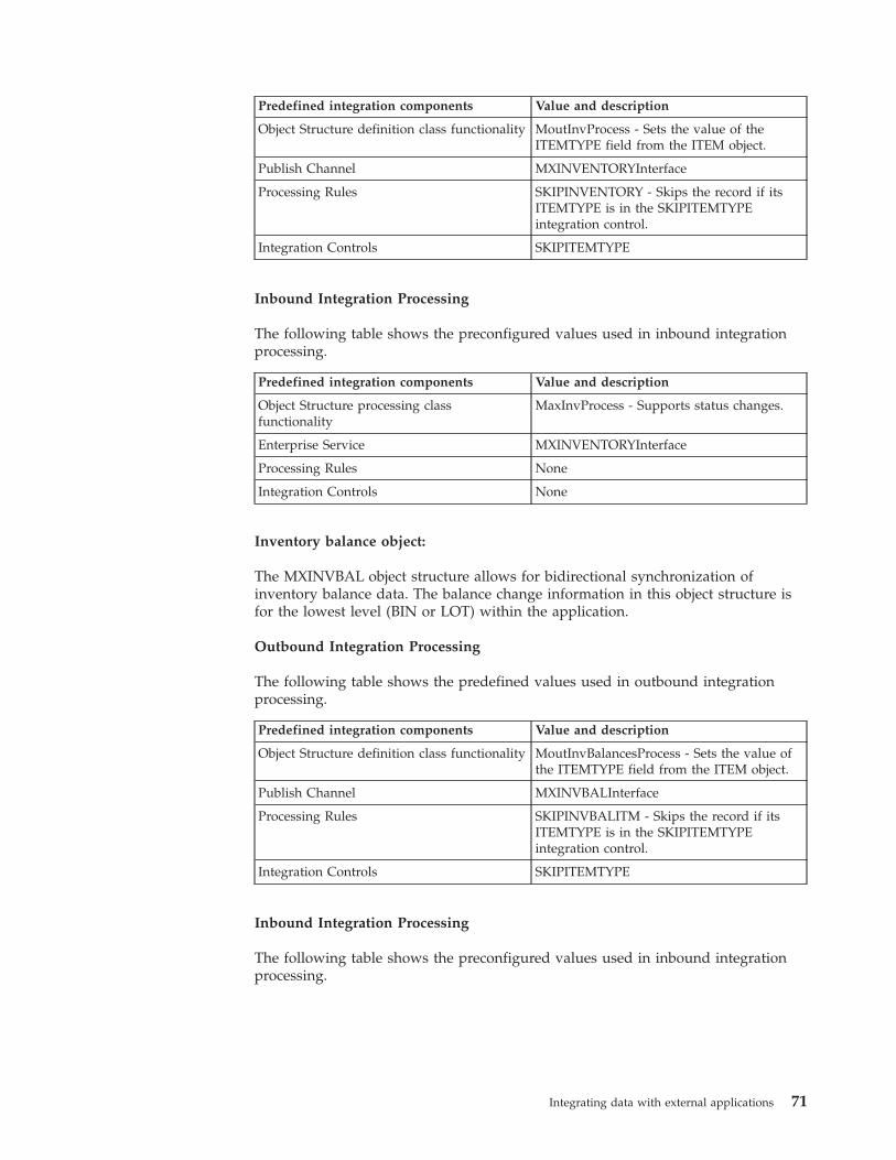
Predefined integration components Value and description
Object Structure definition class functionality MoutInvProcess - Sets the value of theITEMTYPE field from the ITEM object.
Publish Channel MXINVENTORYInterface
Processing Rules SKIPINVENTORY - Skips the record if itsITEMTYPE is in the SKIPITEMTYPEintegration control.
Integration Controls SKIPITEMTYPE
Inbound Integration Processing
The following table shows the preconfigured values used in inbound integrationprocessing.
Predefined integration components Value and description
Object Structure processing classfunctionality
MaxInvProcess - Supports status changes.
Enterprise Service MXINVENTORYInterface
Processing Rules None
Integration Controls None
Inventory balance object:
The MXINVBAL object structure allows for bidirectional synchronization ofinventory balance data. The balance change information in this object structure isfor the lowest level (BIN or LOT) within the application.
Outbound Integration Processing
The following table shows the predefined values used in outbound integrationprocessing.
Predefined integration components Value and description
Object Structure definition class functionality MoutInvBalancesProcess - Sets the value ofthe ITEMTYPE field from the ITEM object.
Publish Channel MXINVBALInterface
Processing Rules SKIPINVBALITM - Skips the record if itsITEMTYPE is in the SKIPITEMTYPEintegration control.
Integration Controls SKIPITEMTYPE
Inbound Integration Processing
The following table shows the preconfigured values used in inbound integrationprocessing.
Integrating data with external applications 71
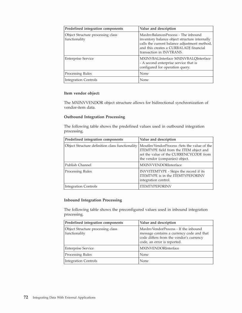
Predefined integration components Value and description
Object Structure processing classfunctionality
MaxInvBalancesProcess - The inboundinventory balance object structure internallycalls the current balance adjustment method,and this creates a CURBALADJ financialtransaction in INVTRANS.
Enterprise Service MXINVBALInterface MXINVBALQInterface- A second enterprise service that isconfigured for operation query.
Processing Rules None
Integration Controls None
Item vendor object:
The MXINVVENDOR object structure allows for bidirectional synchronization ofvendor-item data.
Outbound Integration Processing
The following table shows the predefined values used in outbound integrationprocessing.
Predefined integration components Value and description
Object Structure definition class functionality MoutInvVendorProcess -Sets the value of theITEMTYPE field from the ITEM object andset the value of the CURRENCYCODE fromthe vendor (companies) object.
Publish Channel MXINVVENDORInterface
Processing Rules INVVITEMTYPE - Skips the record if itsITEMTYPE is in the ITEMTYPEFORINVintegration control.
Integration Controls ITEMTYPEFORINV
Inbound Integration Processing
The following table shows the preconfigured values used in inbound integrationprocessing.
Predefined integration components Value and description
Object Structure processing classfunctionality
MaxInvVendorProcess - If the inboundmessage contains a currency code and thatcode differs from the vendor's currencycode, an error is reported.
Enterprise Service MXINVENDORInterface
Processing Rules None
Integration Controls None
72 Integrating Data With External Applications
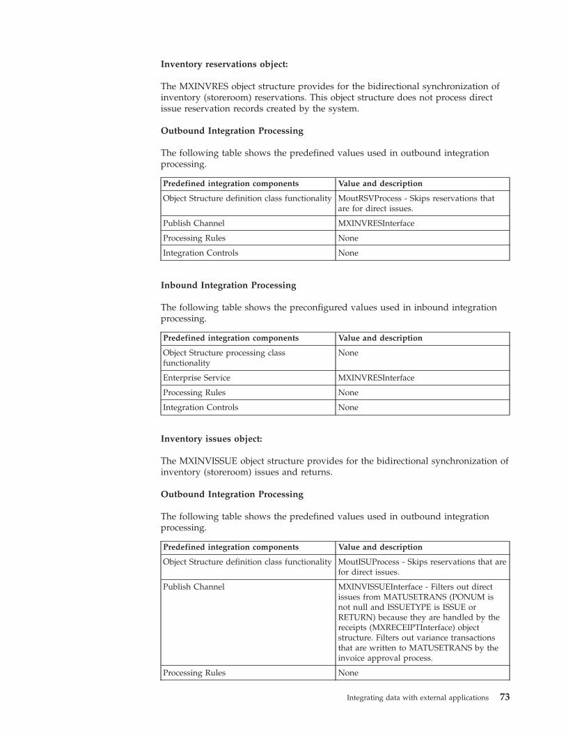
Inventory reservations object:
The MXINVRES object structure provides for the bidirectional synchronization ofinventory (storeroom) reservations. This object structure does not process directissue reservation records created by the system.
Outbound Integration Processing
The following table shows the predefined values used in outbound integrationprocessing.
Predefined integration components Value and description
Object Structure definition class functionality MoutRSVProcess - Skips reservations thatare for direct issues.
Publish Channel MXINVRESInterface
Processing Rules None
Integration Controls None
Inbound Integration Processing
The following table shows the preconfigured values used in inbound integrationprocessing.
Predefined integration components Value and description
Object Structure processing classfunctionality
None
Enterprise Service MXINVRESInterface
Processing Rules None
Integration Controls None
Inventory issues object:
The MXINVISSUE object structure provides for the bidirectional synchronization ofinventory (storeroom) issues and returns.
Outbound Integration Processing
The following table shows the predefined values used in outbound integrationprocessing.
Predefined integration components Value and description
Object Structure definition class functionality MoutISUProcess - Skips reservations that arefor direct issues.
Publish Channel MXINVISSUEInterface - Filters out directissues from MATUSETRANS (PONUM isnot null and ISSUETYPE is ISSUE orRETURN) because they are handled by thereceipts (MXRECEIPTInterface) objectstructure. Filters out variance transactionsthat are written to MATUSETRANS by theinvoice approval process.
Processing Rules None
Integrating data with external applications 73
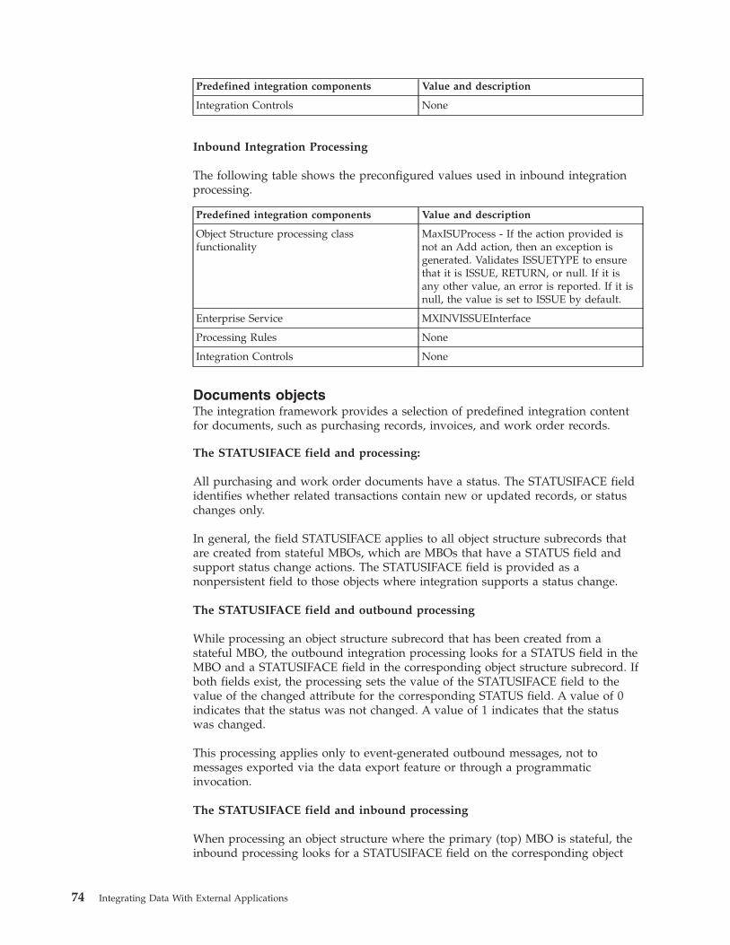
Predefined integration components Value and description
Integration Controls None
Inbound Integration Processing
The following table shows the preconfigured values used in inbound integrationprocessing.
Predefined integration components Value and description
Object Structure processing classfunctionality
MaxISUProcess - If the action provided isnot an Add action, then an exception isgenerated. Validates ISSUETYPE to ensurethat it is ISSUE, RETURN, or null. If it isany other value, an error is reported. If it isnull, the value is set to ISSUE by default.
Enterprise Service MXINVISSUEInterface
Processing Rules None
Integration Controls None
Documents objectsThe integration framework provides a selection of predefined integration contentfor documents, such as purchasing records, invoices, and work order records.
The STATUSIFACE field and processing:
All purchasing and work order documents have a status. The STATUSIFACE fieldidentifies whether related transactions contain new or updated records, or statuschanges only.
In general, the field STATUSIFACE applies to all object structure subrecords thatare created from stateful MBOs, which are MBOs that have a STATUS field andsupport status change actions. The STATUSIFACE field is provided as anonpersistent field to those objects where integration supports a status change.
The STATUSIFACE field and outbound processing
While processing an object structure subrecord that has been created from astateful MBO, the outbound integration processing looks for a STATUS field in theMBO and a STATUSIFACE field in the corresponding object structure subrecord. Ifboth fields exist, the processing sets the value of the STATUSIFACE field to thevalue of the changed attribute for the corresponding STATUS field. A value of 0indicates that the status was not changed. A value of 1 indicates that the statuswas changed.
This processing applies only to event-generated outbound messages, not tomessages exported via the data export feature or through a programmaticinvocation.
The STATUSIFACE field and inbound processing
When processing an object structure where the primary (top) MBO is stateful, theinbound processing looks for a STATUSIFACE field on the corresponding object
74 Integrating Data With External Applications
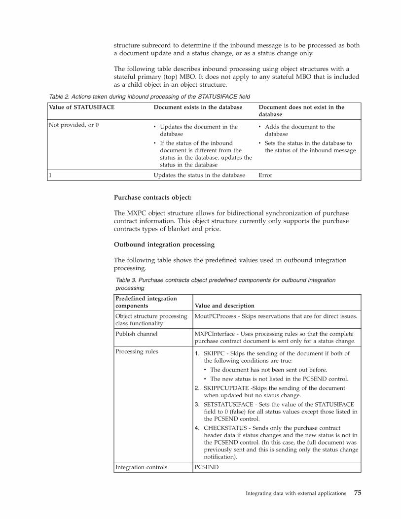
structure subrecord to determine if the inbound message is to be processed as botha document update and a status change, or as a status change only.
The following table describes inbound processing using object structures with astateful primary (top) MBO. It does not apply to any stateful MBO that is includedas a child object in an object structure.
Table 2. Actions taken during inbound processing of the STATUSIFACE field
Value of STATUSIFACE Document exists in the database Document does not exist in thedatabase
Not provided, or 0 v Updates the document in thedatabase
v If the status of the inbounddocument is different from thestatus in the database, updates thestatus in the database
v Adds the document to thedatabase
v Sets the status in the database tothe status of the inbound message
1 Updates the status in the database Error
Purchase contracts object:
The MXPC object structure allows for bidirectional synchronization of purchasecontract information. This object structure currently only supports the purchasecontracts types of blanket and price.
Outbound integration processing
The following table shows the predefined values used in outbound integrationprocessing.
Table 3. Purchase contracts object predefined components for outbound integrationprocessing
Predefined integrationcomponents Value and description
Object structure processingclass functionality
MoutPCProcess - Skips reservations that are for direct issues.
Publish channel MXPCInterface - Uses processing rules so that the completepurchase contract document is sent only for a status change.
Processing rules 1. SKIPPC - Skips the sending of the document if both ofthe following conditions are true:
v The document has not been sent out before.
v The new status is not listed in the PCSEND control.
2. SKIPPCUPDATE -Skips the sending of the documentwhen updated but no status change.
3. SETSTATUSIFACE - Sets the value of the STATUSIFACEfield to 0 (false) for all status values except those listed inthe PCSEND control.
4. CHECKSTATUS - Sends only the purchase contractheader data if status changes and the new status is not inthe PCSEND control. (In this case, the full document waspreviously sent and this is sending only the status changenotification).
Integration controls PCSEND
Integrating data with external applications 75
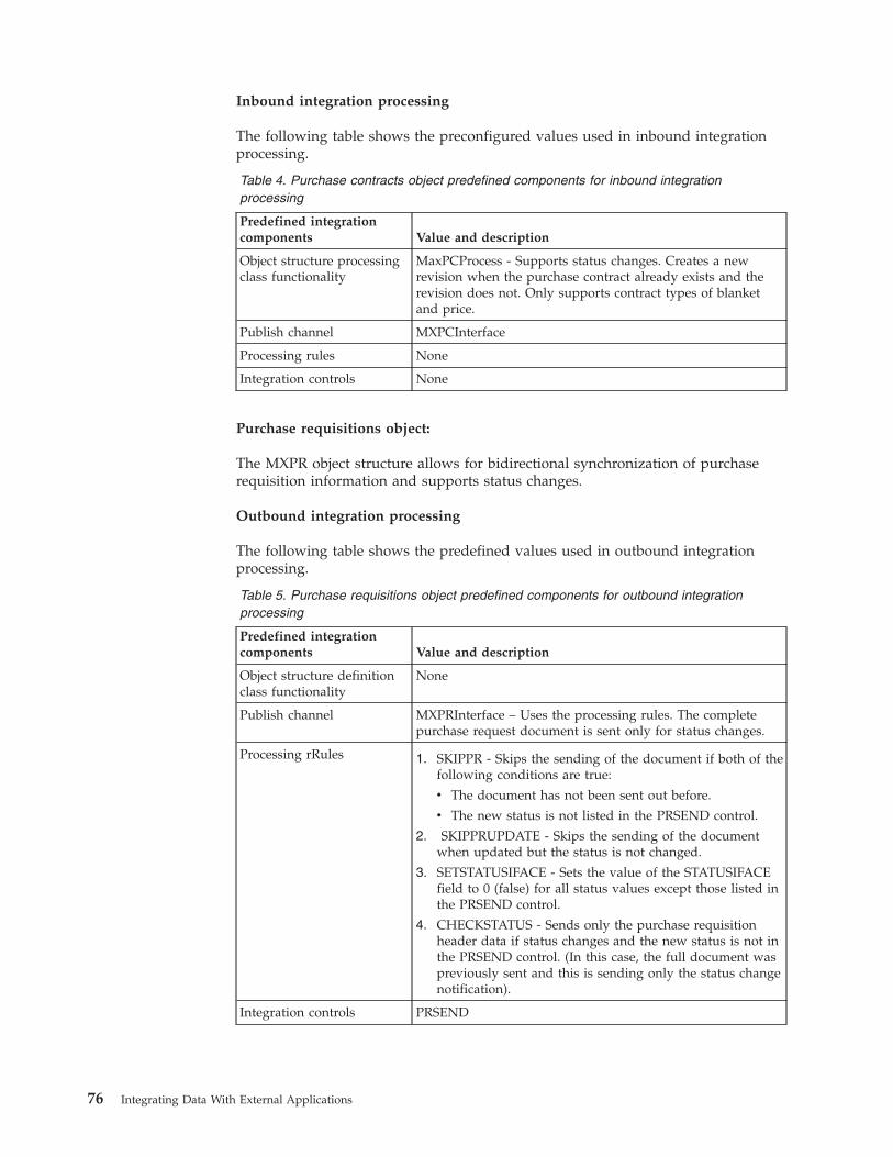
Inbound integration processing
The following table shows the preconfigured values used in inbound integrationprocessing.
Table 4. Purchase contracts object predefined components for inbound integrationprocessing
Predefined integrationcomponents Value and description
Object structure processingclass functionality
MaxPCProcess - Supports status changes. Creates a newrevision when the purchase contract already exists and therevision does not. Only supports contract types of blanketand price.
Publish channel MXPCInterface
Processing rules None
Integration controls None
Purchase requisitions object:
The MXPR object structure allows for bidirectional synchronization of purchaserequisition information and supports status changes.
Outbound integration processing
The following table shows the predefined values used in outbound integrationprocessing.
Table 5. Purchase requisitions object predefined components for outbound integrationprocessing
Predefined integrationcomponents Value and description
Object structure definitionclass functionality
None
Publish channel MXPRInterface – Uses the processing rules. The completepurchase request document is sent only for status changes.
Processing rRules 1. SKIPPR - Skips the sending of the document if both of thefollowing conditions are true:
v The document has not been sent out before.
v The new status is not listed in the PRSEND control.
2. SKIPPRUPDATE - Skips the sending of the documentwhen updated but the status is not changed.
3. SETSTATUSIFACE - Sets the value of the STATUSIFACEfield to 0 (false) for all status values except those listed inthe PRSEND control.
4. CHECKSTATUS - Sends only the purchase requisitionheader data if status changes and the new status is not inthe PRSEND control. (In this case, the full document waspreviously sent and this is sending only the status changenotification).
Integration controls PRSEND
76 Integrating Data With External Applications
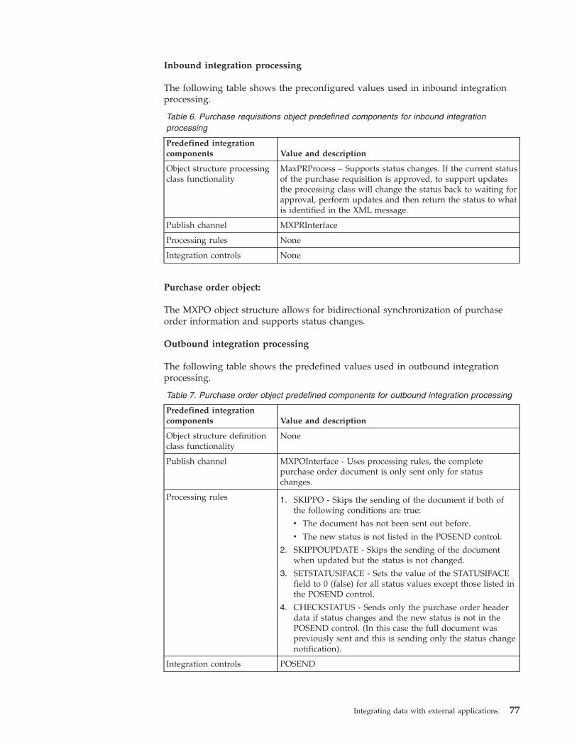
Inbound integration processing
The following table shows the preconfigured values used in inbound integrationprocessing.
Table 6. Purchase requisitions object predefined components for inbound integrationprocessing
Predefined integrationcomponents Value and description
Object structure processingclass functionality
MaxPRProcess – Supports status changes. If the current statusof the purchase requisition is approved, to support updatesthe processing class will change the status back to waiting forapproval, perform updates and then return the status to whatis identified in the XML message.
Publish channel MXPRInterface
Processing rules None
Integration controls None
Purchase order object:
The MXPO object structure allows for bidirectional synchronization of purchaseorder information and supports status changes.
Outbound integration processing
The following table shows the predefined values used in outbound integrationprocessing.
Table 7. Purchase order object predefined components for outbound integration processing
Predefined integrationcomponents Value and description
Object structure definitionclass functionality
None
Publish channel MXPOInterface - Uses processing rules, the completepurchase order document is only sent only for statuschanges.
Processing rules 1. SKIPPO - Skips the sending of the document if both ofthe following conditions are true:
v The document has not been sent out before.
v The new status is not listed in the POSEND control.
2. SKIPPOUPDATE - Skips the sending of the documentwhen updated but the status is not changed.
3. SETSTATUSIFACE - Sets the value of the STATUSIFACEfield to 0 (false) for all status values except those listed inthe POSEND control.
4. CHECKSTATUS - Sends only the purchase order headerdata if status changes and the new status is not in thePOSEND control. (In this case the full document waspreviously sent and this is sending only the status changenotification).
Integration controls POSEND
Integrating data with external applications 77
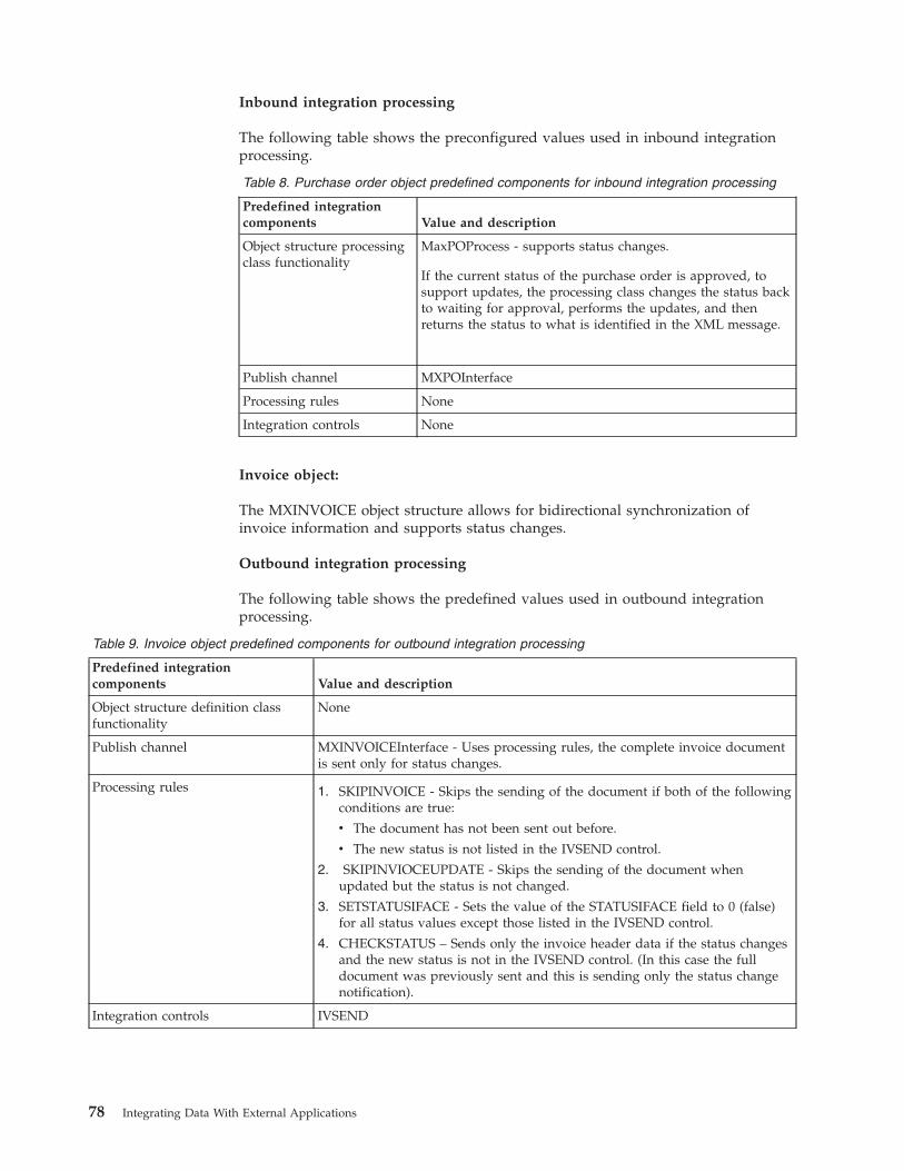
Inbound integration processing
The following table shows the preconfigured values used in inbound integrationprocessing.
Table 8. Purchase order object predefined components for inbound integration processing
Predefined integrationcomponents Value and description
Object structure processingclass functionality
MaxPOProcess - supports status changes.
If the current status of the purchase order is approved, tosupport updates, the processing class changes the status backto waiting for approval, performs the updates, and thenreturns the status to what is identified in the XML message.
Publish channel MXPOInterface
Processing rules None
Integration controls None
Invoice object:
The MXINVOICE object structure allows for bidirectional synchronization ofinvoice information and supports status changes.
Outbound integration processing
The following table shows the predefined values used in outbound integrationprocessing.
Table 9. Invoice object predefined components for outbound integration processing
Predefined integrationcomponents Value and description
Object structure definition classfunctionality
None
Publish channel MXINVOICEInterface - Uses processing rules, the complete invoice documentis sent only for status changes.
Processing rules 1. SKIPINVOICE - Skips the sending of the document if both of the followingconditions are true:
v The document has not been sent out before.
v The new status is not listed in the IVSEND control.
2. SKIPINVIOCEUPDATE - Skips the sending of the document whenupdated but the status is not changed.
3. SETSTATUSIFACE - Sets the value of the STATUSIFACE field to 0 (false)for all status values except those listed in the IVSEND control.
4. CHECKSTATUS – Sends only the invoice header data if the status changesand the new status is not in the IVSEND control. (In this case the fulldocument was previously sent and this is sending only the status changenotification).
Integration controls IVSEND
78 Integrating Data With External Applications
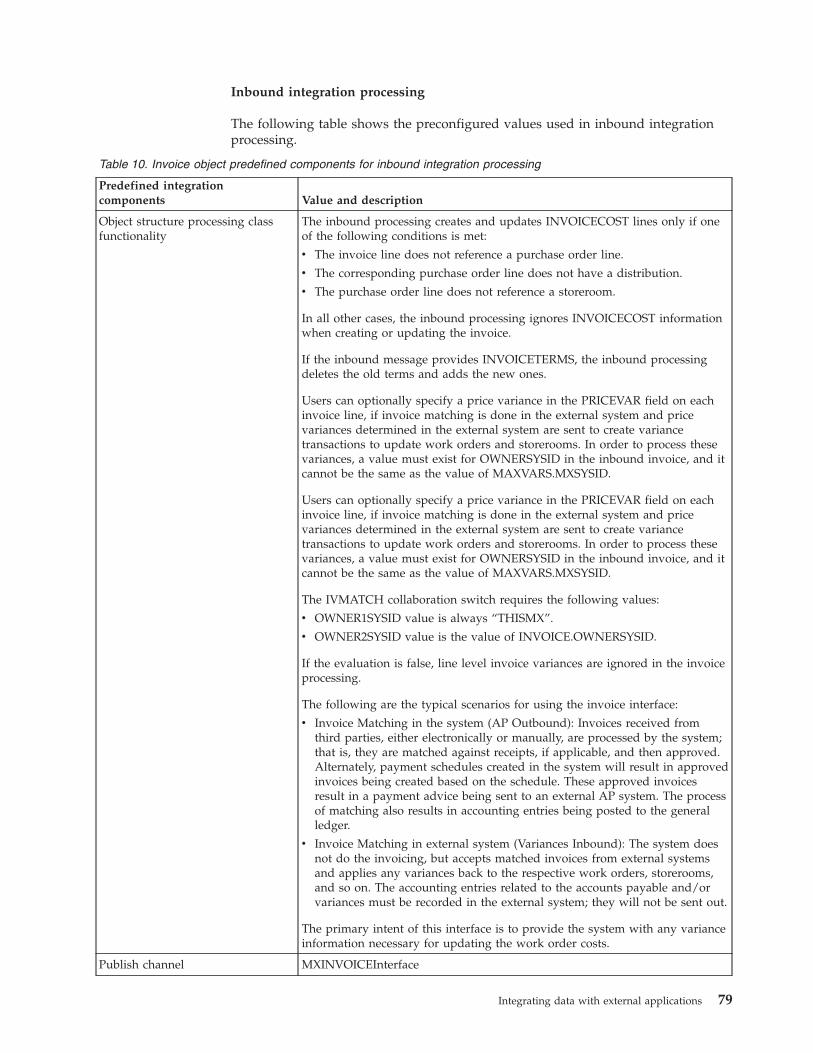
Inbound integration processing
The following table shows the preconfigured values used in inbound integrationprocessing.
Table 10. Invoice object predefined components for inbound integration processing
Predefined integrationcomponents Value and description
Object structure processing classfunctionality
The inbound processing creates and updates INVOICECOST lines only if oneof the following conditions is met:
v The invoice line does not reference a purchase order line.
v The corresponding purchase order line does not have a distribution.
v The purchase order line does not reference a storeroom.
In all other cases, the inbound processing ignores INVOICECOST informationwhen creating or updating the invoice.
If the inbound message provides INVOICETERMS, the inbound processingdeletes the old terms and adds the new ones.
Users can optionally specify a price variance in the PRICEVAR field on eachinvoice line, if invoice matching is done in the external system and pricevariances determined in the external system are sent to create variancetransactions to update work orders and storerooms. In order to process thesevariances, a value must exist for OWNERSYSID in the inbound invoice, and itcannot be the same as the value of MAXVARS.MXSYSID.
Users can optionally specify a price variance in the PRICEVAR field on eachinvoice line, if invoice matching is done in the external system and pricevariances determined in the external system are sent to create variancetransactions to update work orders and storerooms. In order to process thesevariances, a value must exist for OWNERSYSID in the inbound invoice, and itcannot be the same as the value of MAXVARS.MXSYSID.
The IVMATCH collaboration switch requires the following values:
v OWNER1SYSID value is always “THISMX”.
v OWNER2SYSID value is the value of INVOICE.OWNERSYSID.
If the evaluation is false, line level invoice variances are ignored in the invoiceprocessing.
The following are the typical scenarios for using the invoice interface:
v Invoice Matching in the system (AP Outbound): Invoices received fromthird parties, either electronically or manually, are processed by the system;that is, they are matched against receipts, if applicable, and then approved.Alternately, payment schedules created in the system will result in approvedinvoices being created based on the schedule. These approved invoicesresult in a payment advice being sent to an external AP system. The processof matching also results in accounting entries being posted to the generalledger.
v Invoice Matching in external system (Variances Inbound): The system doesnot do the invoicing, but accepts matched invoices from external systemsand applies any variances back to the respective work orders, storerooms,and so on. The accounting entries related to the accounts payable and/orvariances must be recorded in the external system; they will not be sent out.
The primary intent of this interface is to provide the system with any varianceinformation necessary for updating the work order costs.
Publish channel MXINVOICEInterface
Integrating data with external applications 79
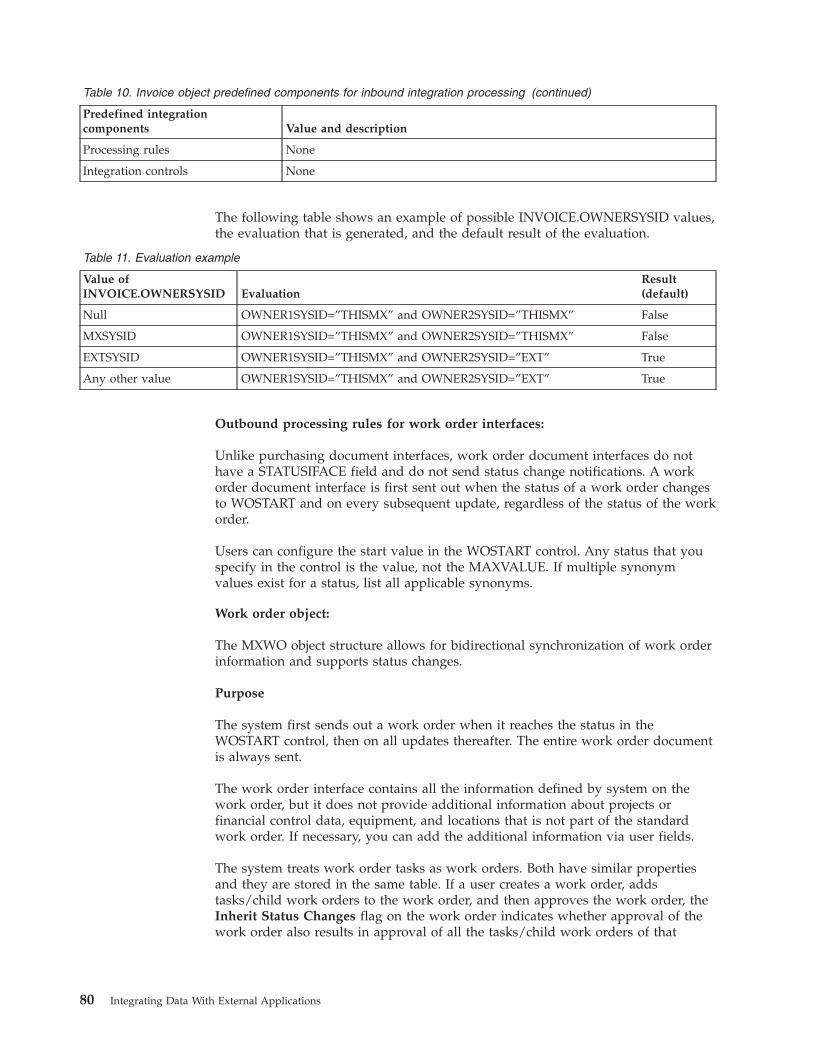
Table 10. Invoice object predefined components for inbound integration processing (continued)
Predefined integrationcomponents Value and description
Processing rules None
Integration controls None
The following table shows an example of possible INVOICE.OWNERSYSID values,the evaluation that is generated, and the default result of the evaluation.
Table 11. Evaluation example
Value ofINVOICE.OWNERSYSID Evaluation
Result(default)
Null OWNER1SYSID=”THISMX” and OWNER2SYSID=”THISMX” False
MXSYSID OWNER1SYSID=”THISMX” and OWNER2SYSID=”THISMX” False
EXTSYSID OWNER1SYSID=”THISMX” and OWNER2SYSID=”EXT” True
Any other value OWNER1SYSID=”THISMX” and OWNER2SYSID=”EXT” True
Outbound processing rules for work order interfaces:
Unlike purchasing document interfaces, work order document interfaces do nothave a STATUSIFACE field and do not send status change notifications. A workorder document interface is first sent out when the status of a work order changesto WOSTART and on every subsequent update, regardless of the status of the workorder.
Users can configure the start value in the WOSTART control. Any status that youspecify in the control is the value, not the MAXVALUE. If multiple synonymvalues exist for a status, list all applicable synonyms.
Work order object:
The MXWO object structure allows for bidirectional synchronization of work orderinformation and supports status changes.
Purpose
The system first sends out a work order when it reaches the status in theWOSTART control, then on all updates thereafter. The entire work order documentis always sent.
The work order interface contains all the information defined by system on thework order, but it does not provide additional information about projects orfinancial control data, equipment, and locations that is not part of the standardwork order. If necessary, you can add the additional information via user fields.
The system treats work order tasks as work orders. Both have similar propertiesand they are stored in the same table. If a user creates a work order, addstasks/child work orders to the work order, and then approves the work order, theInherit Status Changes flag on the work order indicates whether approval of thework order also results in approval of all the tasks/child work orders of that
80 Integrating Data With External Applications
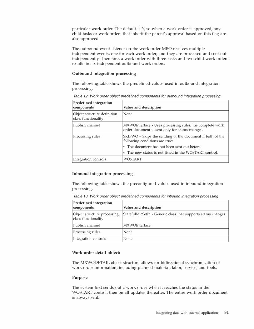
particular work order. The default is Y, so when a work order is approved, anychild tasks or work orders that inherit the parent's approval based on this flag arealso approved.
The outbound event listener on the work order MBO receives multipleindependent events, one for each work order, and they are processed and sent outindependently. Therefore, a work order with three tasks and two child work ordersresults in six independent outbound work orders.
Outbound integration processing
The following table shows the predefined values used in outbound integrationprocessing.
Table 12. Work order object predefined components for outbound integration processing
Predefined integrationcomponents Value and description
Object structure definitionclass functionality
None
Publish channel MXWOInterface - Uses processing rules, the complete workorder document is sent only for status changes.
Processing rules SKIPWO – Skips the sending of the document if both of thefollowing conditions are true:
v The document has not been sent out before.
v The new status is not listed in the WOSTART control.
Integration controls WOSTART
Inbound integration processing
The following table shows the preconfigured values used in inbound integrationprocessing.
Table 13. Work order object predefined components for inbound integration processing
Predefined integrationcomponents Value and description
Object structure processingclass functionality
StatefulMicSetIn - Generic class that supports status changes.
Publish channel MXWOInterface
Processing rules None
Integration controls None
Work order detail object:
The MXWODETAIL object structure allows for bidirectional synchronization ofwork order information, including planned material, labor, service, and tools.
Purpose
The system first sends out a work order when it reaches the status in theWOSTART control, then on all updates thereafter. The entire work order documentis always sent.
Integrating data with external applications 81
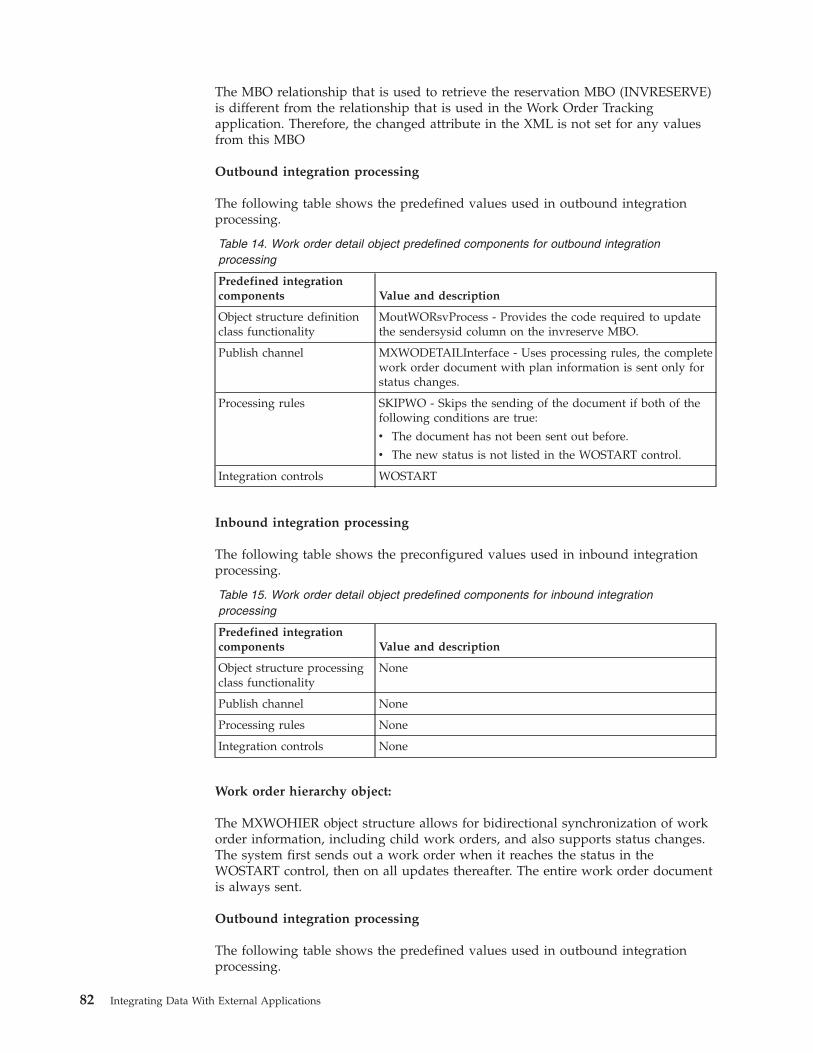
The MBO relationship that is used to retrieve the reservation MBO (INVRESERVE)is different from the relationship that is used in the Work Order Trackingapplication. Therefore, the changed attribute in the XML is not set for any valuesfrom this MBO
Outbound integration processing
The following table shows the predefined values used in outbound integrationprocessing.
Table 14. Work order detail object predefined components for outbound integrationprocessing
Predefined integrationcomponents Value and description
Object structure definitionclass functionality
MoutWORsvProcess - Provides the code required to updatethe sendersysid column on the invreserve MBO.
Publish channel MXWODETAILInterface - Uses processing rules, the completework order document with plan information is sent only forstatus changes.
Processing rules SKIPWO - Skips the sending of the document if both of thefollowing conditions are true:
v The document has not been sent out before.
v The new status is not listed in the WOSTART control.
Integration controls WOSTART
Inbound integration processing
The following table shows the preconfigured values used in inbound integrationprocessing.
Table 15. Work order detail object predefined components for inbound integrationprocessing
Predefined integrationcomponents Value and description
Object structure processingclass functionality
None
Publish channel None
Processing rules None
Integration controls None
Work order hierarchy object:
The MXWOHIER object structure allows for bidirectional synchronization of workorder information, including child work orders, and also supports status changes.The system first sends out a work order when it reaches the status in theWOSTART control, then on all updates thereafter. The entire work order documentis always sent.
Outbound integration processing
The following table shows the predefined values used in outbound integrationprocessing.
82 Integrating Data With External Applications
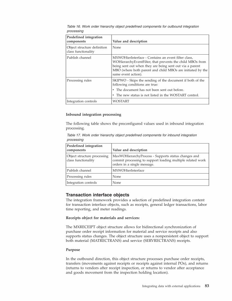
Table 16. Work order hierarchy object predefined components for outbound integrationprocessing
Predefined integrationcomponents Value and description
Object structure definitionclass functionality
None
Publish channel MXWOHierInterface - Contains an event filter class,WOHierarchyEventFilter, that prevents the child MBOs frombeing sent out when they are being sent out via a parentMBO (where both parent and child MBOs are initiated by thesame event action).
Processing rules SKIPWO - Skips the sending of the document if both of thefollowing conditions are true:
v The document has not been sent out before.
v The new status is not listed in the WOSTART control.
Integration controls WOSTART
Inbound integration processing
The following table shows the preconfigured values used in inbound integrationprocessing.
Table 17. Work order hierarchy object predefined components for inbound integrationprocessing
Predefined integrationcomponents Value and description
Object structure processingclass functionality
MaxWOHierarchyProcess - Supports status changes andcommit processing to support loading multiple related workorders in a single message.
Publish channel MXWOHierInterface
Processing rules None
Integration controls None
Transaction interface objectsThe integration framework provides a selection of predefined integration contentfor transaction interface objects, such as receipts, general ledger transactions, labortime reporting, and meter readings.
Receipts object for materials and services:
The MXRECEIPT object structure allows for bidirectional synchronization ofpurchase order receipt information for material and service receipts and alsosupports status changes. The object structure uses a nonpersistent object to supportboth material (MATRECTRANS) and service (SERVRECTRANS) receipts.
Purpose
In the outbound direction, this object structure processes purchase order receipts,transfers (movements against receipts or receipts against internal POs), and returns(returns to vendors after receipt inspection, or returns to vendor after acceptanceand goods movement from the inspection holding location).
Integrating data with external applications 83
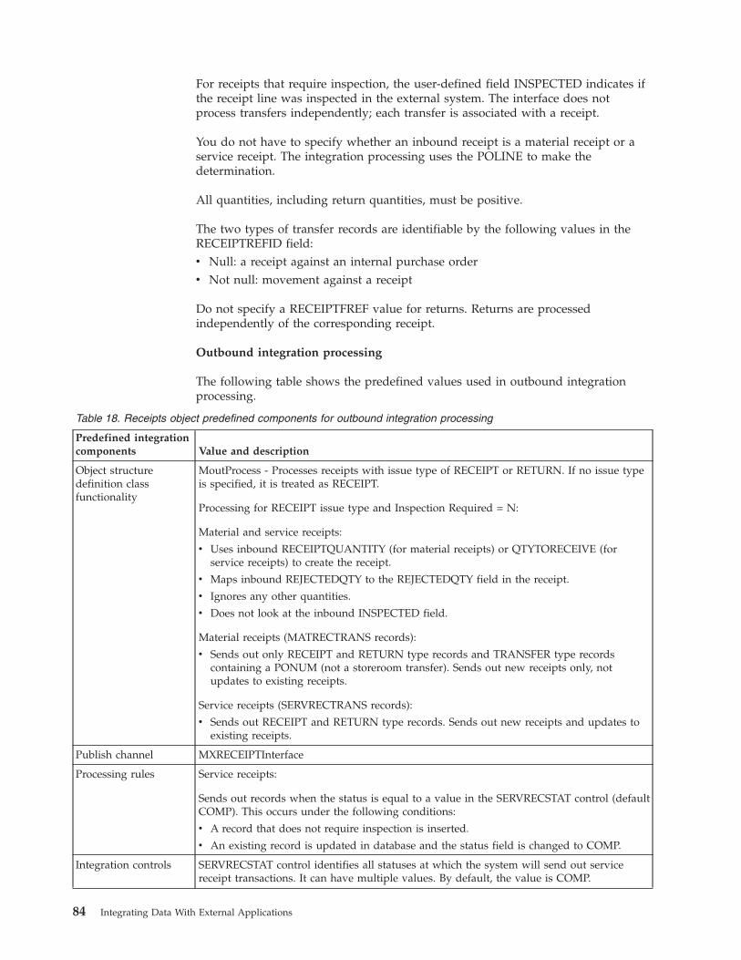
For receipts that require inspection, the user-defined field INSPECTED indicates ifthe receipt line was inspected in the external system. The interface does notprocess transfers independently; each transfer is associated with a receipt.
You do not have to specify whether an inbound receipt is a material receipt or aservice receipt. The integration processing uses the POLINE to make thedetermination.
All quantities, including return quantities, must be positive.
The two types of transfer records are identifiable by the following values in theRECEIPTREFID field:v Null: a receipt against an internal purchase orderv Not null: movement against a receipt
Do not specify a RECEIPTFREF value for returns. Returns are processedindependently of the corresponding receipt.
Outbound integration processing
The following table shows the predefined values used in outbound integrationprocessing.
Table 18. Receipts object predefined components for outbound integration processing
Predefined integrationcomponents Value and description
Object structuredefinition classfunctionality
MoutProcess - Processes receipts with issue type of RECEIPT or RETURN. If no issue typeis specified, it is treated as RECEIPT.
Processing for RECEIPT issue type and Inspection Required = N:
Material and service receipts:
v Uses inbound RECEIPTQUANTITY (for material receipts) or QTYTORECEIVE (forservice receipts) to create the receipt.
v Maps inbound REJECTEDQTY to the REJECTEDQTY field in the receipt.
v Ignores any other quantities.
v Does not look at the inbound INSPECTED field.
Material receipts (MATRECTRANS records):
v Sends out only RECEIPT and RETURN type records and TRANSFER type recordscontaining a PONUM (not a storeroom transfer). Sends out new receipts only, notupdates to existing receipts.
Service receipts (SERVRECTRANS records):
v Sends out RECEIPT and RETURN type records. Sends out new receipts and updates toexisting receipts.
Publish channel MXRECEIPTInterface
Processing rules Service receipts:
Sends out records when the status is equal to a value in the SERVRECSTAT control (defaultCOMP). This occurs under the following conditions:
v A record that does not require inspection is inserted.
v An existing record is updated in database and the status field is changed to COMP.
Integration controls SERVRECSTAT control identifies all statuses at which the system will send out servicereceipt transactions. It can have multiple values. By default, the value is COMP.
84 Integrating Data With External Applications

Inbound integration processing
The following table shows the preconfigured values used in inbound integrationprocessing.
Integrating data with external applications 85
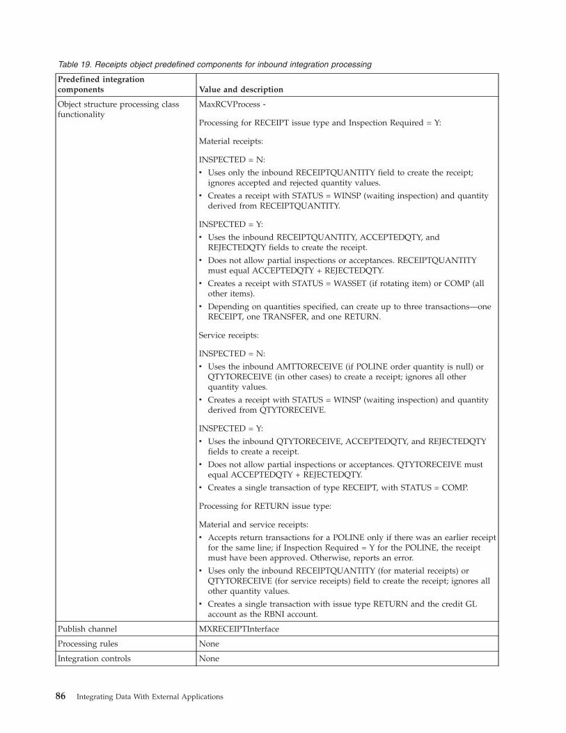
Table 19. Receipts object predefined components for inbound integration processing
Predefined integrationcomponents Value and description
Object structure processing classfunctionality
MaxRCVProcess -
Processing for RECEIPT issue type and Inspection Required = Y:
Material receipts:
INSPECTED = N:
v Uses only the inbound RECEIPTQUANTITY field to create the receipt;ignores accepted and rejected quantity values.
v Creates a receipt with STATUS = WINSP (waiting inspection) and quantityderived from RECEIPTQUANTITY.
INSPECTED = Y:
v Uses the inbound RECEIPTQUANTITY, ACCEPTEDQTY, andREJECTEDQTY fields to create the receipt.
v Does not allow partial inspections or acceptances. RECEIPTQUANTITYmust equal ACCEPTEDQTY + REJECTEDQTY.
v Creates a receipt with STATUS = WASSET (if rotating item) or COMP (allother items).
v Depending on quantities specified, can create up to three transactions—oneRECEIPT, one TRANSFER, and one RETURN.
Service receipts:
INSPECTED = N:
v Uses the inbound AMTTORECEIVE (if POLINE order quantity is null) orQTYTORECEIVE (in other cases) to create a receipt; ignores all otherquantity values.
v Creates a receipt with STATUS = WINSP (waiting inspection) and quantityderived from QTYTORECEIVE.
INSPECTED = Y:
v Uses the inbound QTYTORECEIVE, ACCEPTEDQTY, and REJECTEDQTYfields to create a receipt.
v Does not allow partial inspections or acceptances. QTYTORECEIVE mustequal ACCEPTEDQTY + REJECTEDQTY.
v Creates a single transaction of type RECEIPT, with STATUS = COMP.
Processing for RETURN issue type:
Material and service receipts:
v Accepts return transactions for a POLINE only if there was an earlier receiptfor the same line; if Inspection Required = Y for the POLINE, the receiptmust have been approved. Otherwise, reports an error.
v Uses only the inbound RECEIPTQUANTITY (for material receipts) orQTYTORECEIVE (for service receipts) field to create the receipt; ignores allother quantity values.
v Creates a single transaction with issue type RETURN and the credit GLaccount as the RBNI account.
Publish channel MXRECEIPTInterface
Processing rules None
Integration controls None
86 Integrating Data With External Applications
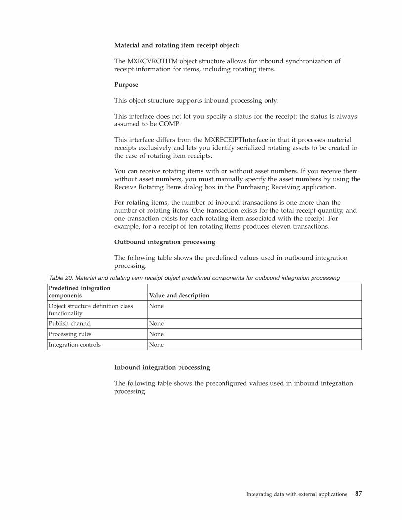
Material and rotating item receipt object:
The MXRCVROTITM object structure allows for inbound synchronization ofreceipt information for items, including rotating items.
Purpose
This object structure supports inbound processing only.
This interface does not let you specify a status for the receipt; the status is alwaysassumed to be COMP.
This interface differs from the MXRECEIPTInterface in that it processes materialreceipts exclusively and lets you identify serialized rotating assets to be created inthe case of rotating item receipts.
You can receive rotating items with or without asset numbers. If you receive themwithout asset numbers, you must manually specify the asset numbers by using theReceive Rotating Items dialog box in the Purchasing Receiving application.
For rotating items, the number of inbound transactions is one more than thenumber of rotating items. One transaction exists for the total receipt quantity, andone transaction exists for each rotating item associated with the receipt. Forexample, for a receipt of ten rotating items produces eleven transactions.
Outbound integration processing
The following table shows the predefined values used in outbound integrationprocessing.
Table 20. Material and rotating item receipt object predefined components for outbound integration processing
Predefined integrationcomponents Value and description
Object structure definition classfunctionality
None
Publish channel None
Processing rules None
Integration controls None
Inbound integration processing
The following table shows the preconfigured values used in inbound integrationprocessing.
Integrating data with external applications 87
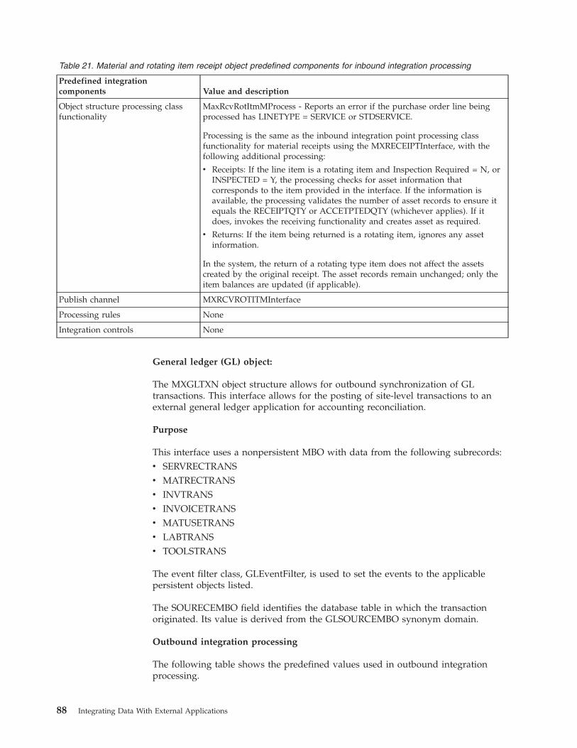
Table 21. Material and rotating item receipt object predefined components for inbound integration processing
Predefined integrationcomponents Value and description
Object structure processing classfunctionality
MaxRcvRotItmMProcess - Reports an error if the purchase order line beingprocessed has LINETYPE = SERVICE or STDSERVICE.
Processing is the same as the inbound integration point processing classfunctionality for material receipts using the MXRECEIPTInterface, with thefollowing additional processing:
v Receipts: If the line item is a rotating item and Inspection Required = N, orINSPECTED = Y, the processing checks for asset information thatcorresponds to the item provided in the interface. If the information isavailable, the processing validates the number of asset records to ensure itequals the RECEIPTQTY or ACCETPTEDQTY (whichever applies). If itdoes, invokes the receiving functionality and creates asset as required.
v Returns: If the item being returned is a rotating item, ignores any assetinformation.
In the system, the return of a rotating type item does not affect the assetscreated by the original receipt. The asset records remain unchanged; only theitem balances are updated (if applicable).
Publish channel MXRCVROTITMInterface
Processing rules None
Integration controls None
General ledger (GL) object:
The MXGLTXN object structure allows for outbound synchronization of GLtransactions. This interface allows for the posting of site-level transactions to anexternal general ledger application for accounting reconciliation.
Purpose
This interface uses a nonpersistent MBO with data from the following subrecords:v SERVRECTRANSv MATRECTRANSv INVTRANSv INVOICETRANSv MATUSETRANSv LABTRANSv TOOLSTRANS
The event filter class, GLEventFilter, is used to set the events to the applicablepersistent objects listed.
The SOURECEMBO field identifies the database table in which the transactionoriginated. Its value is derived from the GLSOURCEMBO synonym domain.
Outbound integration processing
The following table shows the predefined values used in outbound integrationprocessing.
88 Integrating Data With External Applications
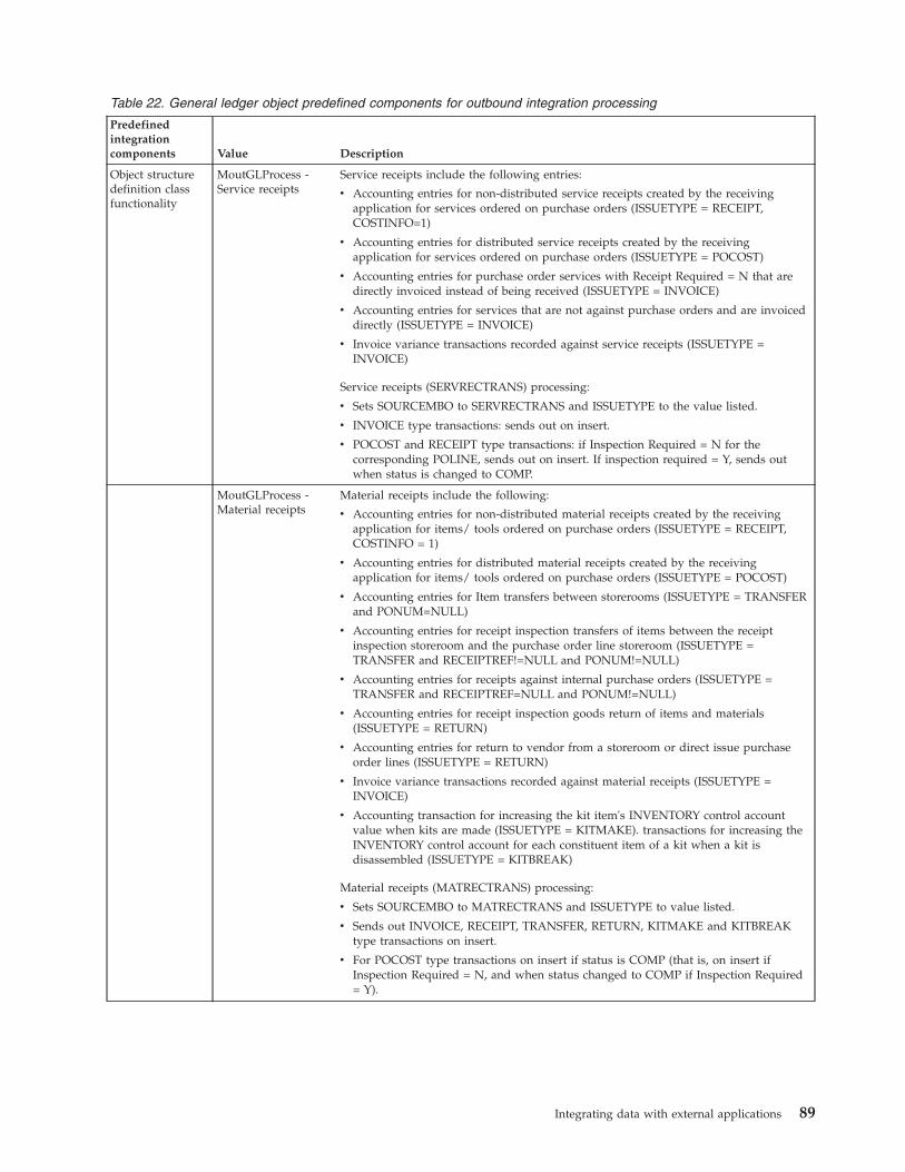
Table 22. General ledger object predefined components for outbound integration processing
Predefinedintegrationcomponents Value Description
Object structuredefinition classfunctionality
MoutGLProcess -Service receipts
Service receipts include the following entries:
v Accounting entries for non-distributed service receipts created by the receivingapplication for services ordered on purchase orders (ISSUETYPE = RECEIPT,COSTINFO=1)
v Accounting entries for distributed service receipts created by the receivingapplication for services ordered on purchase orders (ISSUETYPE = POCOST)
v Accounting entries for purchase order services with Receipt Required = N that aredirectly invoiced instead of being received (ISSUETYPE = INVOICE)
v Accounting entries for services that are not against purchase orders and are invoiceddirectly (ISSUETYPE = INVOICE)
v Invoice variance transactions recorded against service receipts (ISSUETYPE =INVOICE)
Service receipts (SERVRECTRANS) processing:
v Sets SOURCEMBO to SERVRECTRANS and ISSUETYPE to the value listed.
v INVOICE type transactions: sends out on insert.
v POCOST and RECEIPT type transactions: if Inspection Required = N for thecorresponding POLINE, sends out on insert. If inspection required = Y, sends outwhen status is changed to COMP.
MoutGLProcess -Material receipts
Material receipts include the following:
v Accounting entries for non-distributed material receipts created by the receivingapplication for items/ tools ordered on purchase orders (ISSUETYPE = RECEIPT,COSTINFO = 1)
v Accounting entries for distributed material receipts created by the receivingapplication for items/ tools ordered on purchase orders (ISSUETYPE = POCOST)
v Accounting entries for Item transfers between storerooms (ISSUETYPE = TRANSFERand PONUM=NULL)
v Accounting entries for receipt inspection transfers of items between the receiptinspection storeroom and the purchase order line storeroom (ISSUETYPE =TRANSFER and RECEIPTREF!=NULL and PONUM!=NULL)
v Accounting entries for receipts against internal purchase orders (ISSUETYPE =TRANSFER and RECEIPTREF=NULL and PONUM!=NULL)
v Accounting entries for receipt inspection goods return of items and materials(ISSUETYPE = RETURN)
v Accounting entries for return to vendor from a storeroom or direct issue purchaseorder lines (ISSUETYPE = RETURN)
v Invoice variance transactions recorded against material receipts (ISSUETYPE =INVOICE)
v Accounting transaction for increasing the kit item's INVENTORY control accountvalue when kits are made (ISSUETYPE = KITMAKE). transactions for increasing theINVENTORY control account for each constituent item of a kit when a kit isdisassembled (ISSUETYPE = KITBREAK)
Material receipts (MATRECTRANS) processing:
v Sets SOURCEMBO to MATRECTRANS and ISSUETYPE to value listed.
v Sends out INVOICE, RECEIPT, TRANSFER, RETURN, KITMAKE and KITBREAKtype transactions on insert.
v For POCOST type transactions on insert if status is COMP (that is, on insert ifInspection Required = N, and when status changed to COMP if Inspection Required= Y).
Integrating data with external applications 89
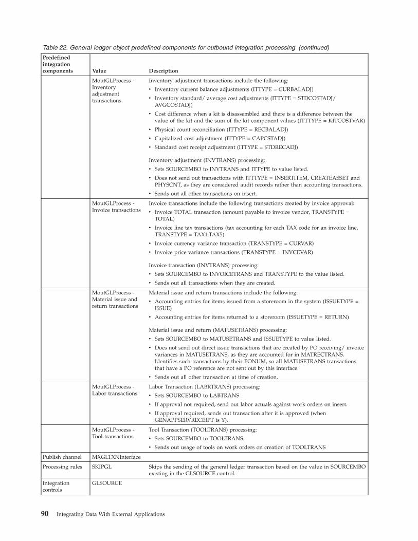
Table 22. General ledger object predefined components for outbound integration processing (continued)
Predefinedintegrationcomponents Value Description
MoutGLProcess -Inventoryadjustmenttransactions
Inventory adjustment transactions include the following:
v Inventory current balance adjustments (ITTYPE = CURBALADJ)
v Inventory standard/ average cost adjustments (ITTYPE = STDCOSTADJ/AVGCOSTADJ)
v Cost difference when a kit is disassembled and there is a difference between thevalue of the kit and the sum of the kit component values (ITTTYPE = KITCOSTVAR)
v Physical count reconciliation (ITTYPE = RECBALADJ)
v Capitalized cost adjustment (ITTYPE = CAPCSTADJ)
v Standard cost receipt adjustment (ITTYPE = STDRECADJ)
Inventory adjustment (INVTRANS) processing:
v Sets SOURCEMBO to INVTRANS and ITTYPE to value listed.
v Does not send out transactions with ITTTYPE = INSERTITEM, CREATEASSET andPHYSCNT, as they are considered audit records rather than accounting transactions.
v Sends out all other transactions on insert.
MoutGLProcess -Invoice transactions
Invoice transactions include the following transactions created by invoice approval:
v Invoice TOTAL transaction (amount payable to invoice vendor, TRANSTYPE =TOTAL)
v Invoice line tax transactions (tax accounting for each TAX code for an invoice line,TRANSTYPE = TAX1:TAX5)
v Invoice currency variance transaction (TRANSTYPE = CURVAR)
v Invoice price variance transactions (TRANSTYPE = INVCEVAR)
Invoice transaction (INVTRANS) processing:
v Sets SOURCEMBO to INVOICETRANS and TRANSTYPE to the value listed.
v Sends out all transactions when they are created.
MoutGLProcess -Material issue andreturn transactions
Material issue and return transactions include the following:
v Accounting entries for items issued from a storeroom in the system (ISSUETYPE =ISSUE)
v Accounting entries for items returned to a storeroom (ISSUETYPE = RETURN)
Material issue and return (MATUSETRANS) processing:
v Sets SOURCEMBO to MATUSETRANS and ISSUETYPE to value listed.
v Does not send out direct issue transactions that are created by PO receiving/ invoicevariances in MATUSETRANS, as they are accounted for in MATRECTRANS.Identifies such transactions by their PONUM, so all MATUSETRANS transactionsthat have a PO reference are not sent out by this interface.
v Sends out all other transaction at time of creation.
MoutGLProcess -Labor transactions
Labor Transaction (LABRTRANS) processing:
v Sets SOURCEMBO to LABTRANS.
v If approval not required, send out labor actuals against work orders on insert.
v If approval required, sends out transaction after it is approved (whenGENAPPSERVRECEIPT is Y).
MoutGLProcess -Tool transactions
Tool Transaction (TOOLTRANS) processing:
v Sets SOURCEMBO to TOOLTRANS.
v Sends out usage of tools on work orders on creation of TOOLTRANS
Publish channel MXGLTXNInterface
Processing rules SKIPGL Skips the sending of the general ledger transaction based on the value in SOURCEMBOexisting in the GLSOURCE control.
Integrationcontrols
GLSOURCE
90 Integrating Data With External Applications
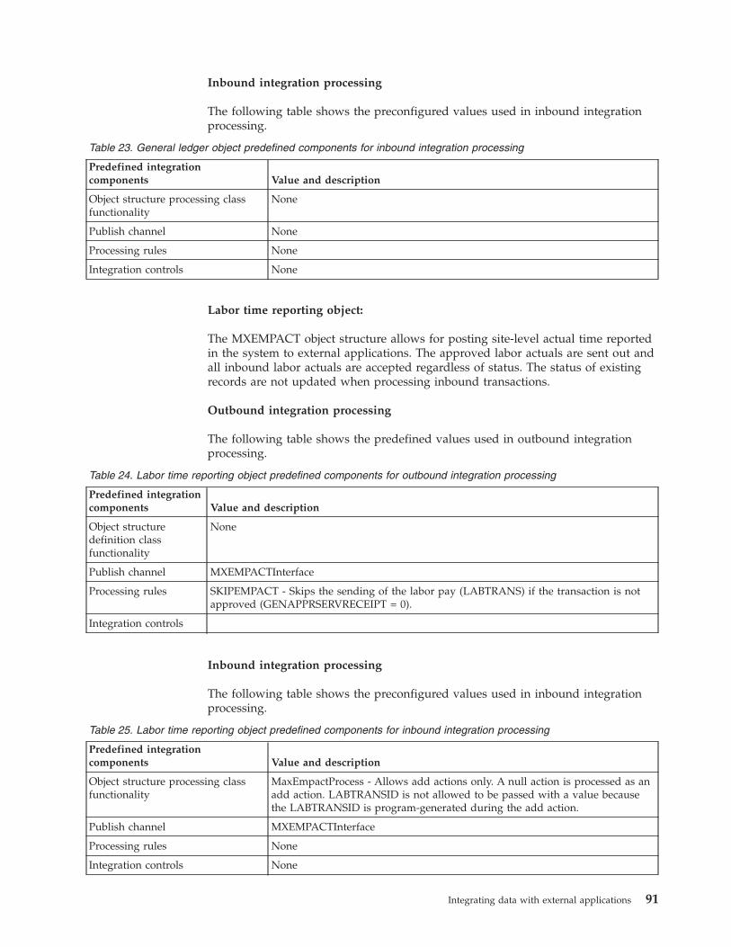
Inbound integration processing
The following table shows the preconfigured values used in inbound integrationprocessing.
Table 23. General ledger object predefined components for inbound integration processing
Predefined integrationcomponents Value and description
Object structure processing classfunctionality
None
Publish channel None
Processing rules None
Integration controls None
Labor time reporting object:
The MXEMPACT object structure allows for posting site-level actual time reportedin the system to external applications. The approved labor actuals are sent out andall inbound labor actuals are accepted regardless of status. The status of existingrecords are not updated when processing inbound transactions.
Outbound integration processing
The following table shows the predefined values used in outbound integrationprocessing.
Table 24. Labor time reporting object predefined components for outbound integration processing
Predefined integrationcomponents Value and description
Object structuredefinition classfunctionality
None
Publish channel MXEMPACTInterface
Processing rules SKIPEMPACT - Skips the sending of the labor pay (LABTRANS) if the transaction is notapproved (GENAPPRSERVRECEIPT = 0).
Integration controls
Inbound integration processing
The following table shows the preconfigured values used in inbound integrationprocessing.
Table 25. Labor time reporting object predefined components for inbound integration processing
Predefined integrationcomponents Value and description
Object structure processing classfunctionality
MaxEmpactProcess - Allows add actions only. A null action is processed as anadd action. LABTRANSID is not allowed to be passed with a value becausethe LABTRANSID is program-generated during the add action.
Publish channel MXEMPACTInterface
Processing rules None
Integration controls None
Integrating data with external applications 91
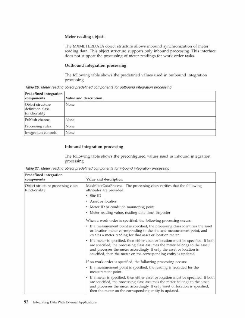
Meter reading object:
The MXMETERDATA object structure allows inbound synchronization of meterreading data. This object structure supports only inbound processing. This interfacedoes not support the processing of meter readings for work order tasks.
Outbound integration processing
The following table shows the predefined values used in outbound integrationprocessing.
Table 26. Meter reading object predefined components for outbound integration processing
Predefined integrationcomponents Value and description
Object structuredefinition classfunctionality
None
Publish channel None
Processing rules None
Integration controls None
Inbound integration processing
The following table shows the preconfigured values used in inbound integrationprocessing.
Table 27. Meter reading object predefined components for inbound integration processing
Predefined integrationcomponents Value and description
Object structure processing classfunctionality
MaxMeterDataProcess - The processing class verifies that the followingattributes are provided:
v Site ID
v Asset or location
v Meter ID or condition monitoring point
v Meter reading value, reading date time, inspector
When a work order is specified, the following processing occurs:
v If a measurement point is specified, the processing class identifies the assetor location meter corresponding to the site and measurement point, andcreates a meter reading for that asset or location meter.
v If a meter is specified, then either asset or location must be specified. If bothare specified, the processing class assumes the meter belongs to the asset,and processes the meter accordingly. If only the asset or location isspecified, then the meter on the corresponding entity is updated.
If no work order is specified, the following processing occurs:
v If a measurement point is specified, the reading is recorded for themeasurement point.
v If a meter is specified, then either asset or location must be specified. If bothare specified, the processing class assumes the meter belongs to the asset,and processes the meter accordingly. If only asset or location is specified,then the meter on the corresponding entity is updated.
92 Integrating Data With External Applications
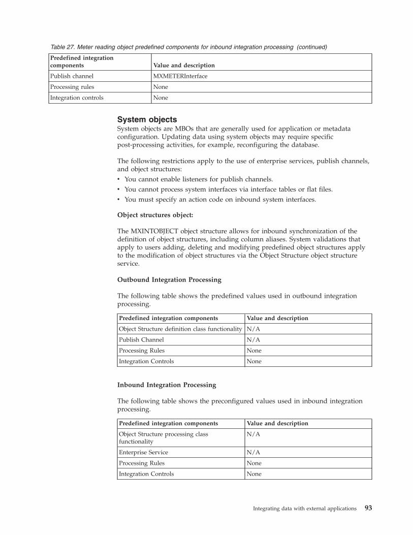
Table 27. Meter reading object predefined components for inbound integration processing (continued)
Predefined integrationcomponents Value and description
Publish channel MXMETERInterface
Processing rules None
Integration controls None
System objectsSystem objects are MBOs that are generally used for application or metadataconfiguration. Updating data using system objects may require specificpost-processing activities, for example, reconfiguring the database.
The following restrictions apply to the use of enterprise services, publish channels,and object structures:v You cannot enable listeners for publish channels.v You cannot process system interfaces via interface tables or flat files.v You must specify an action code on inbound system interfaces.
Object structures object:
The MXINTOBJECT object structure allows for inbound synchronization of thedefinition of object structures, including column aliases. System validations thatapply to users adding, deleting and modifying predefined object structures applyto the modification of object structures via the Object Structure object structureservice.
Outbound Integration Processing
The following table shows the predefined values used in outbound integrationprocessing.
Predefined integration components Value and description
Object Structure definition class functionality N/A
Publish Channel N/A
Processing Rules None
Integration Controls None
Inbound Integration Processing
The following table shows the preconfigured values used in inbound integrationprocessing.
Predefined integration components Value and description
Object Structure processing classfunctionality
N/A
Enterprise Service N/A
Processing Rules None
Integration Controls None
Integrating data with external applications 93
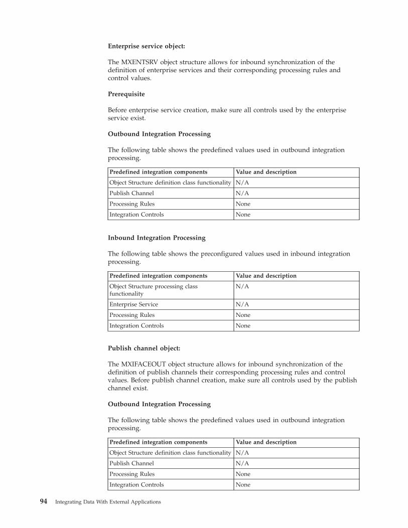
Enterprise service object:
The MXENTSRV object structure allows for inbound synchronization of thedefinition of enterprise services and their corresponding processing rules andcontrol values.
Prerequisite
Before enterprise service creation, make sure all controls used by the enterpriseservice exist.
Outbound Integration Processing
The following table shows the predefined values used in outbound integrationprocessing.
Predefined integration components Value and description
Object Structure definition class functionality N/A
Publish Channel N/A
Processing Rules None
Integration Controls None
Inbound Integration Processing
The following table shows the preconfigured values used in inbound integrationprocessing.
Predefined integration components Value and description
Object Structure processing classfunctionality
N/A
Enterprise Service N/A
Processing Rules None
Integration Controls None
Publish channel object:
The MXIFACEOUT object structure allows for inbound synchronization of thedefinition of publish channels their corresponding processing rules and controlvalues. Before publish channel creation, make sure all controls used by the publishchannel exist.
Outbound Integration Processing
The following table shows the predefined values used in outbound integrationprocessing.
Predefined integration components Value and description
Object Structure definition class functionality N/A
Publish Channel N/A
Processing Rules None
Integration Controls None
94 Integrating Data With External Applications
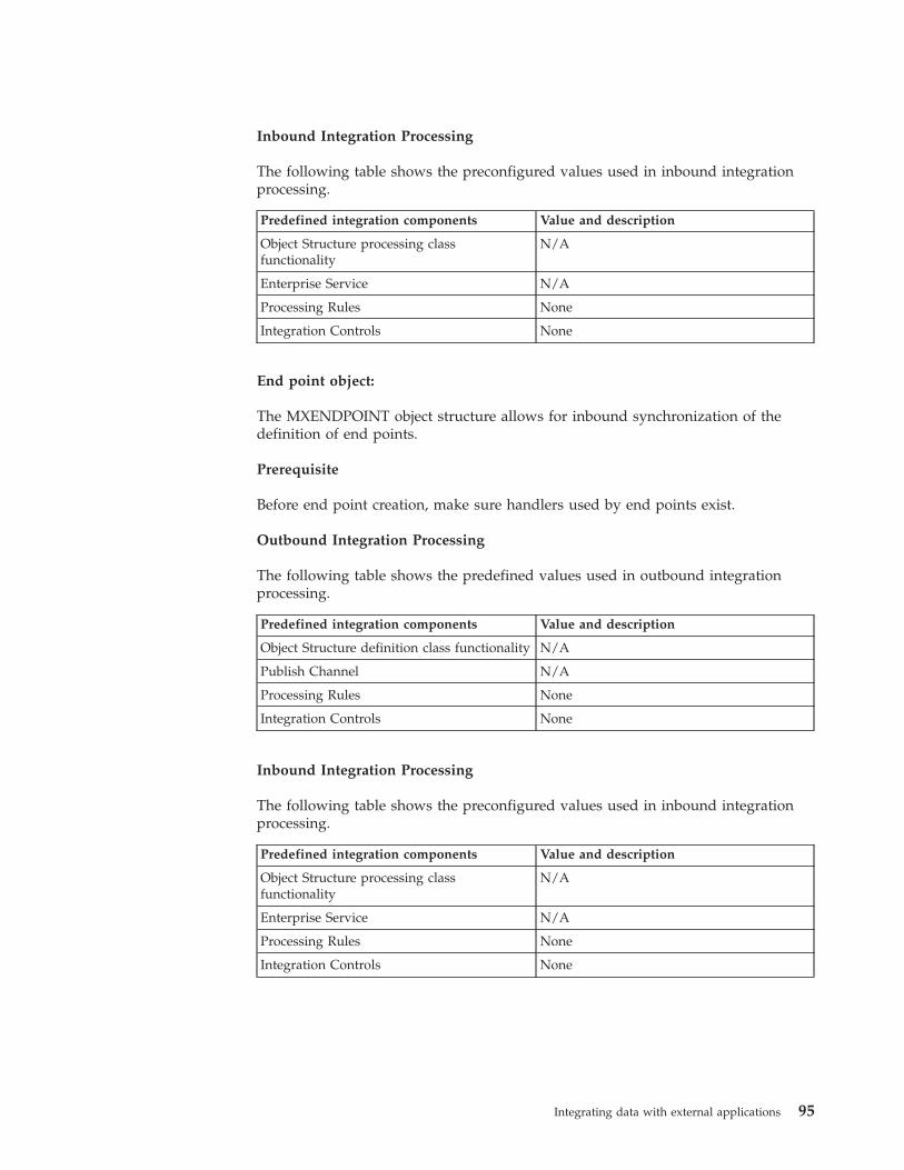
Inbound Integration Processing
The following table shows the preconfigured values used in inbound integrationprocessing.
Predefined integration components Value and description
Object Structure processing classfunctionality
N/A
Enterprise Service N/A
Processing Rules None
Integration Controls None
End point object:
The MXENDPOINT object structure allows for inbound synchronization of thedefinition of end points.
Prerequisite
Before end point creation, make sure handlers used by end points exist.
Outbound Integration Processing
The following table shows the predefined values used in outbound integrationprocessing.
Predefined integration components Value and description
Object Structure definition class functionality N/A
Publish Channel N/A
Processing Rules None
Integration Controls None
Inbound Integration Processing
The following table shows the preconfigured values used in inbound integrationprocessing.
Predefined integration components Value and description
Object Structure processing classfunctionality
N/A
Enterprise Service N/A
Processing Rules None
Integration Controls None
Integrating data with external applications 95
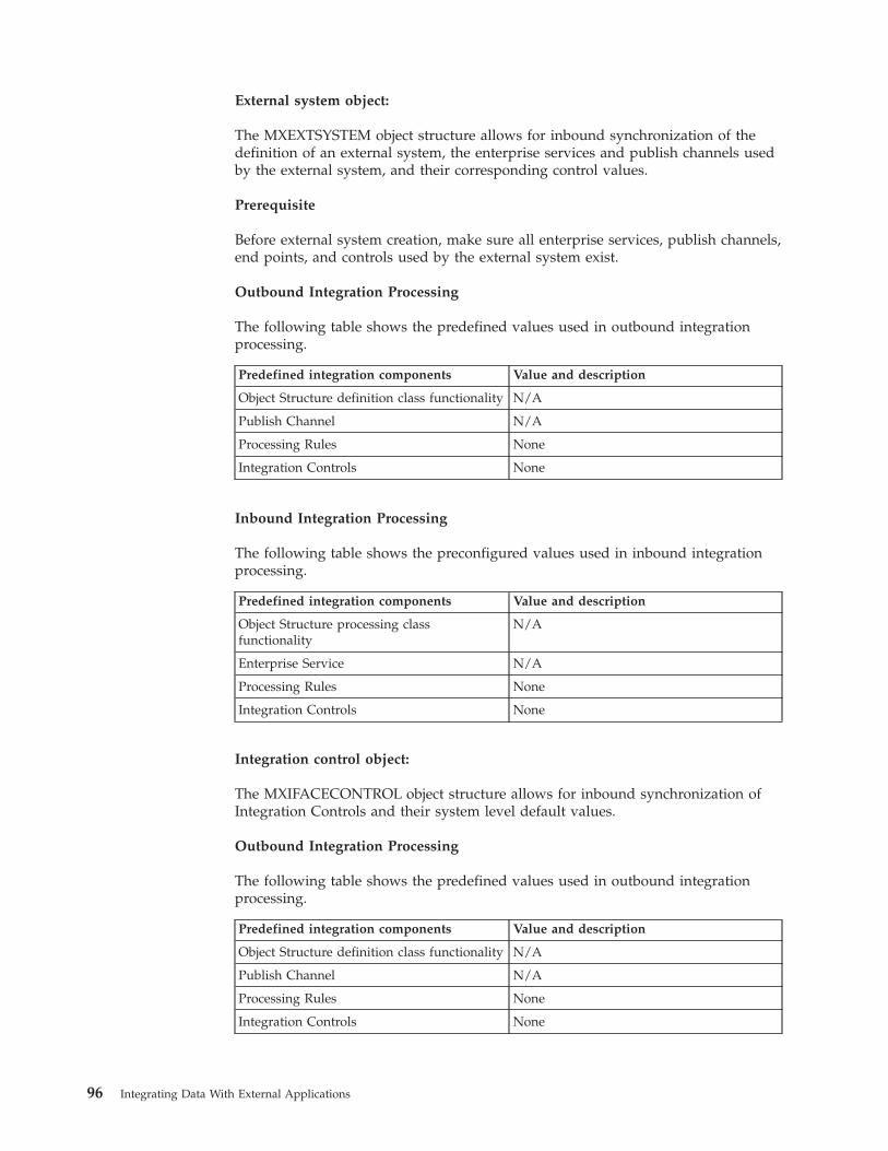
External system object:
The MXEXTSYSTEM object structure allows for inbound synchronization of thedefinition of an external system, the enterprise services and publish channels usedby the external system, and their corresponding control values.
Prerequisite
Before external system creation, make sure all enterprise services, publish channels,end points, and controls used by the external system exist.
Outbound Integration Processing
The following table shows the predefined values used in outbound integrationprocessing.
Predefined integration components Value and description
Object Structure definition class functionality N/A
Publish Channel N/A
Processing Rules None
Integration Controls None
Inbound Integration Processing
The following table shows the preconfigured values used in inbound integrationprocessing.
Predefined integration components Value and description
Object Structure processing classfunctionality
N/A
Enterprise Service N/A
Processing Rules None
Integration Controls None
Integration control object:
The MXIFACECONTROL object structure allows for inbound synchronization ofIntegration Controls and their system level default values.
Outbound Integration Processing
The following table shows the predefined values used in outbound integrationprocessing.
Predefined integration components Value and description
Object Structure definition class functionality N/A
Publish Channel N/A
Processing Rules None
Integration Controls None
96 Integrating Data With External Applications
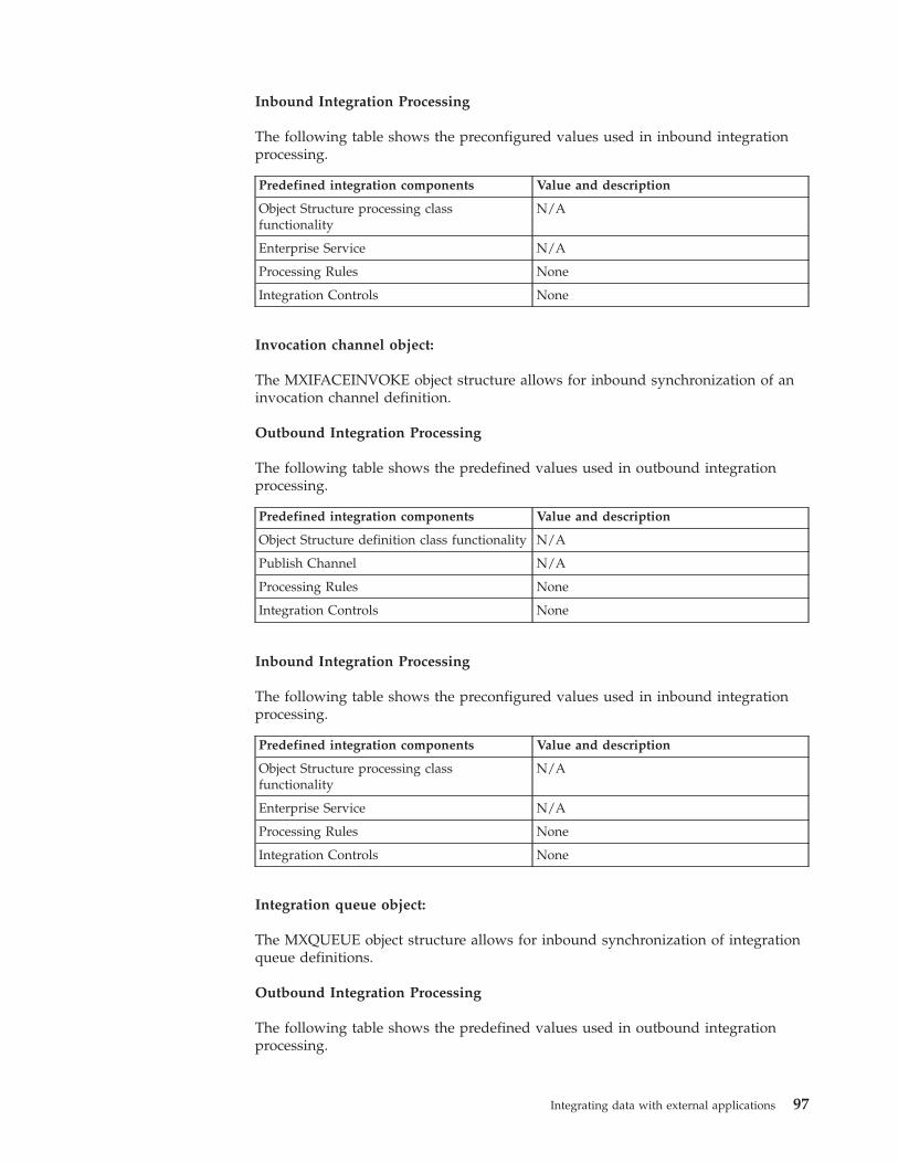
Inbound Integration Processing
The following table shows the preconfigured values used in inbound integrationprocessing.
Predefined integration components Value and description
Object Structure processing classfunctionality
N/A
Enterprise Service N/A
Processing Rules None
Integration Controls None
Invocation channel object:
The MXIFACEINVOKE object structure allows for inbound synchronization of aninvocation channel definition.
Outbound Integration Processing
The following table shows the predefined values used in outbound integrationprocessing.
Predefined integration components Value and description
Object Structure definition class functionality N/A
Publish Channel N/A
Processing Rules None
Integration Controls None
Inbound Integration Processing
The following table shows the preconfigured values used in inbound integrationprocessing.
Predefined integration components Value and description
Object Structure processing classfunctionality
N/A
Enterprise Service N/A
Processing Rules None
Integration Controls None
Integration queue object:
The MXQUEUE object structure allows for inbound synchronization of integrationqueue definitions.
Outbound Integration Processing
The following table shows the predefined values used in outbound integrationprocessing.
Integrating data with external applications 97
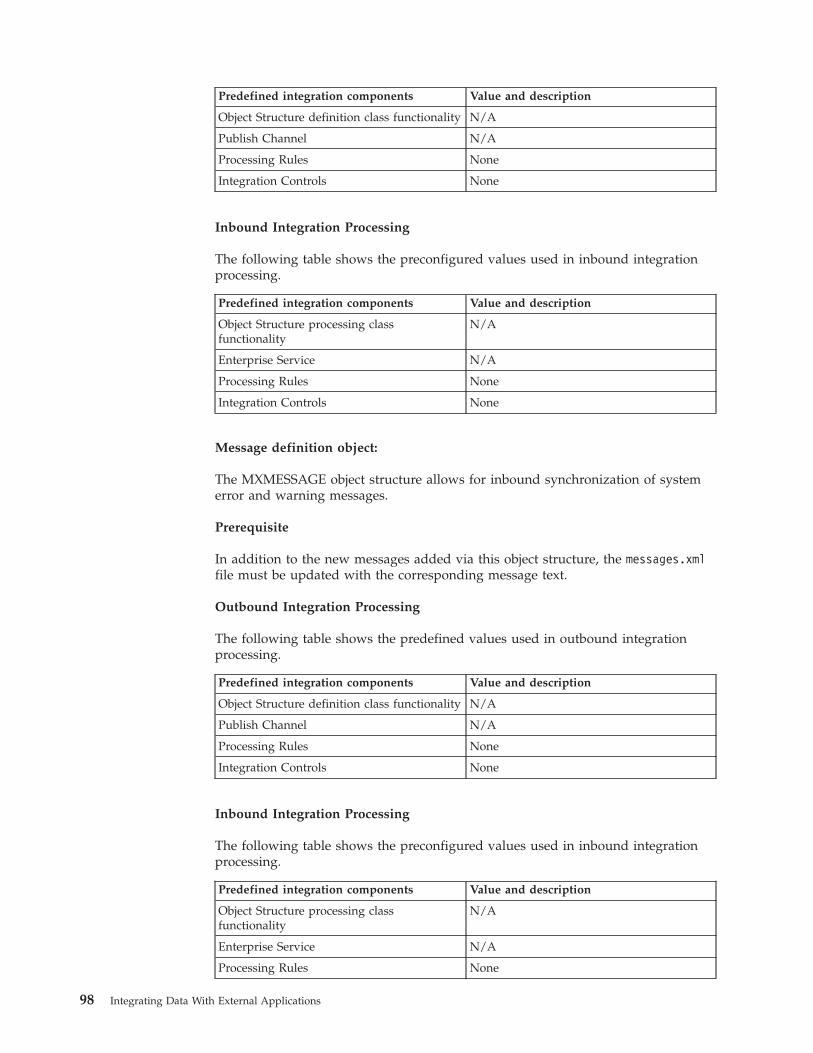
Predefined integration components Value and description
Object Structure definition class functionality N/A
Publish Channel N/A
Processing Rules None
Integration Controls None
Inbound Integration Processing
The following table shows the preconfigured values used in inbound integrationprocessing.
Predefined integration components Value and description
Object Structure processing classfunctionality
N/A
Enterprise Service N/A
Processing Rules None
Integration Controls None
Message definition object:
The MXMESSAGE object structure allows for inbound synchronization of systemerror and warning messages.
Prerequisite
In addition to the new messages added via this object structure, the messages.xmlfile must be updated with the corresponding message text.
Outbound Integration Processing
The following table shows the predefined values used in outbound integrationprocessing.
Predefined integration components Value and description
Object Structure definition class functionality N/A
Publish Channel N/A
Processing Rules None
Integration Controls None
Inbound Integration Processing
The following table shows the preconfigured values used in inbound integrationprocessing.
Predefined integration components Value and description
Object Structure processing classfunctionality
N/A
Enterprise Service N/A
Processing Rules None
98 Integrating Data With External Applications
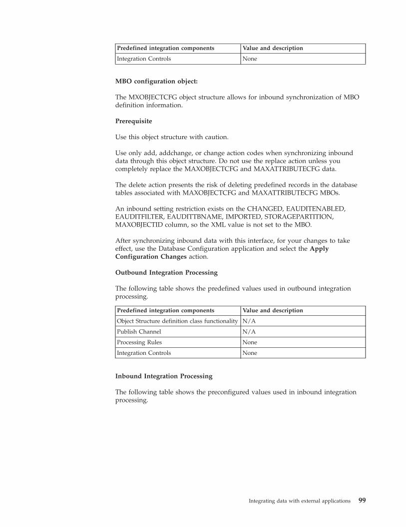
Predefined integration components Value and description
Integration Controls None
MBO configuration object:
The MXOBJECTCFG object structure allows for inbound synchronization of MBOdefinition information.
Prerequisite
Use this object structure with caution.
Use only add, addchange, or change action codes when synchronizing inbounddata through this object structure. Do not use the replace action unless youcompletely replace the MAXOBJECTCFG and MAXATTRIBUTECFG data.
The delete action presents the risk of deleting predefined records in the databasetables associated with MAXOBJECTCFG and MAXATTRIBUTECFG MBOs.
An inbound setting restriction exists on the CHANGED, EAUDITENABLED,EAUDITFILTER, EAUDITTBNAME, IMPORTED, STORAGEPARTITION,MAXOBJECTID column, so the XML value is not set to the MBO.
After synchronizing inbound data with this interface, for your changes to takeeffect, use the Database Configuration application and select the ApplyConfiguration Changes action.
Outbound Integration Processing
The following table shows the predefined values used in outbound integrationprocessing.
Predefined integration components Value and description
Object Structure definition class functionality N/A
Publish Channel N/A
Processing Rules None
Integration Controls None
Inbound Integration Processing
The following table shows the preconfigured values used in inbound integrationprocessing.
Integrating data with external applications 99
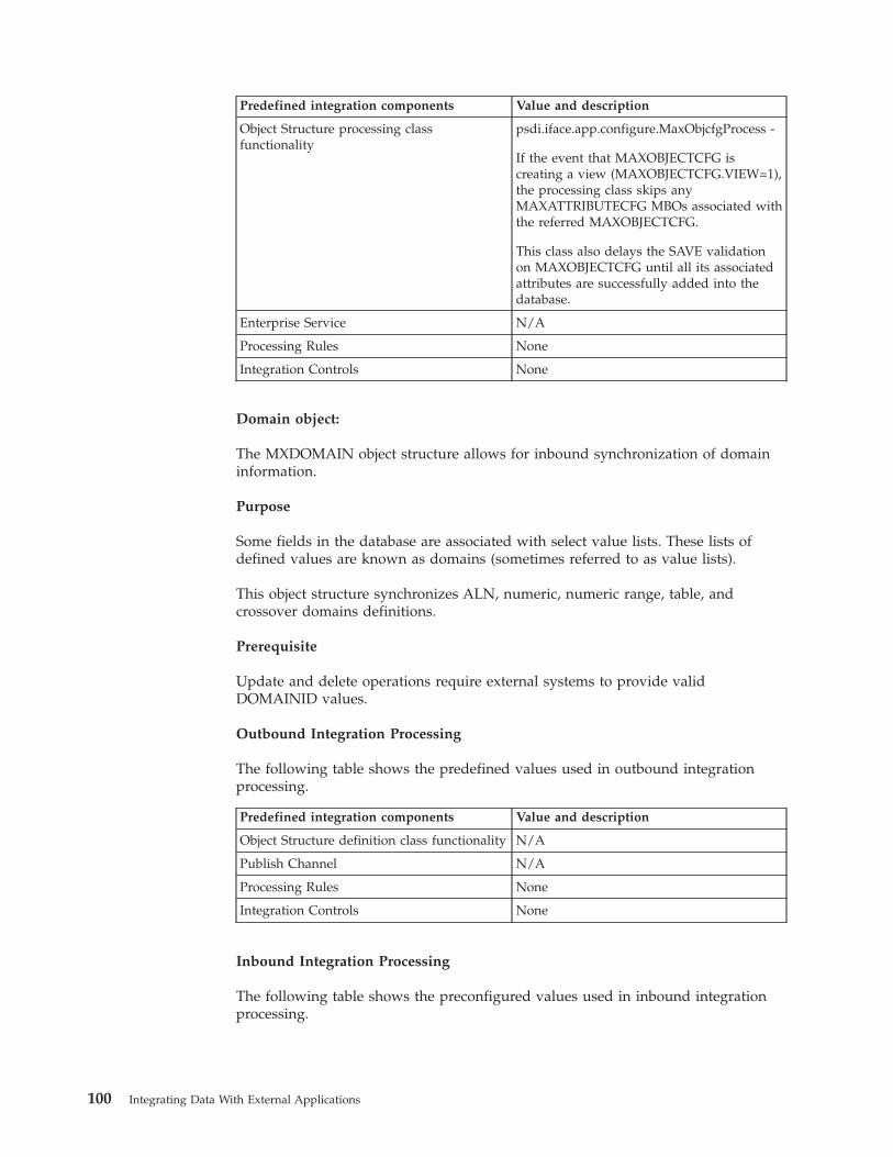
Predefined integration components Value and description
Object Structure processing classfunctionality
psdi.iface.app.configure.MaxObjcfgProcess -
If the event that MAXOBJECTCFG iscreating a view (MAXOBJECTCFG.VIEW=1),the processing class skips anyMAXATTRIBUTECFG MBOs associated withthe referred MAXOBJECTCFG.
This class also delays the SAVE validationon MAXOBJECTCFG until all its associatedattributes are successfully added into thedatabase.
Enterprise Service N/A
Processing Rules None
Integration Controls None
Domain object:
The MXDOMAIN object structure allows for inbound synchronization of domaininformation.
Purpose
Some fields in the database are associated with select value lists. These lists ofdefined values are known as domains (sometimes referred to as value lists).
This object structure synchronizes ALN, numeric, numeric range, table, andcrossover domains definitions.
Prerequisite
Update and delete operations require external systems to provide validDOMAINID values.
Outbound Integration Processing
The following table shows the predefined values used in outbound integrationprocessing.
Predefined integration components Value and description
Object Structure definition class functionality N/A
Publish Channel N/A
Processing Rules None
Integration Controls None
Inbound Integration Processing
The following table shows the preconfigured values used in inbound integrationprocessing.
100 Integrating Data With External Applications
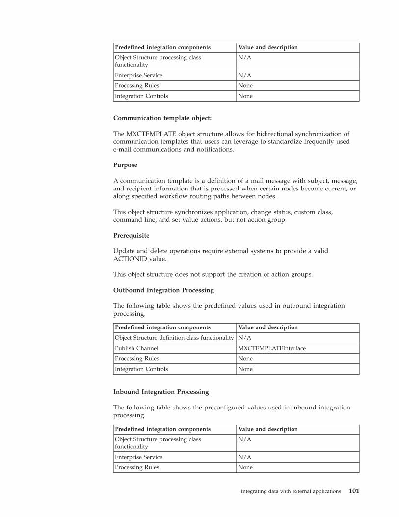
Predefined integration components Value and description
Object Structure processing classfunctionality
N/A
Enterprise Service N/A
Processing Rules None
Integration Controls None
Communication template object:
The MXCTEMPLATE object structure allows for bidirectional synchronization ofcommunication templates that users can leverage to standardize frequently usede-mail communications and notifications.
Purpose
A communication template is a definition of a mail message with subject, message,and recipient information that is processed when certain nodes become current, oralong specified workflow routing paths between nodes.
This object structure synchronizes application, change status, custom class,command line, and set value actions, but not action group.
Prerequisite
Update and delete operations require external systems to provide a validACTIONID value.
This object structure does not support the creation of action groups.
Outbound Integration Processing
The following table shows the predefined values used in outbound integrationprocessing.
Predefined integration components Value and description
Object Structure definition class functionality N/A
Publish Channel MXCTEMPLATEInterface
Processing Rules None
Integration Controls None
Inbound Integration Processing
The following table shows the preconfigured values used in inbound integrationprocessing.
Predefined integration components Value and description
Object Structure processing classfunctionality
N/A
Enterprise Service N/A
Processing Rules None
Integrating data with external applications 101
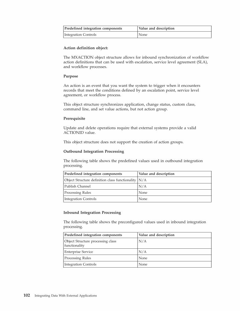
Predefined integration components Value and description
Integration Controls None
Action definition object:
The MXACTION object structure allows for inbound synchronization of workflowaction definitions that can be used with escalation, service level agreement (SLA),and workflow processes.
Purpose
An action is an event that you want the system to trigger when it encountersrecords that meet the conditions defined by an escalation point, service levelagreement, or workflow process.
This object structure synchronizes application, change status, custom class,command line, and set value actions, but not action group.
Prerequisite
Update and delete operations require that external systems provide a validACTIONID value.
This object structure does not support the creation of action groups.
Outbound Integration Processing
The following table shows the predefined values used in outbound integrationprocessing.
Predefined integration components Value and description
Object Structure definition class functionality N/A
Publish Channel N/A
Processing Rules None
Integration Controls None
Inbound Integration Processing
The following table shows the preconfigured values used in inbound integrationprocessing.
Predefined integration components Value and description
Object Structure processing classfunctionality
N/A
Enterprise Service N/A
Processing Rules None
Integration Controls None
102 Integrating Data With External Applications
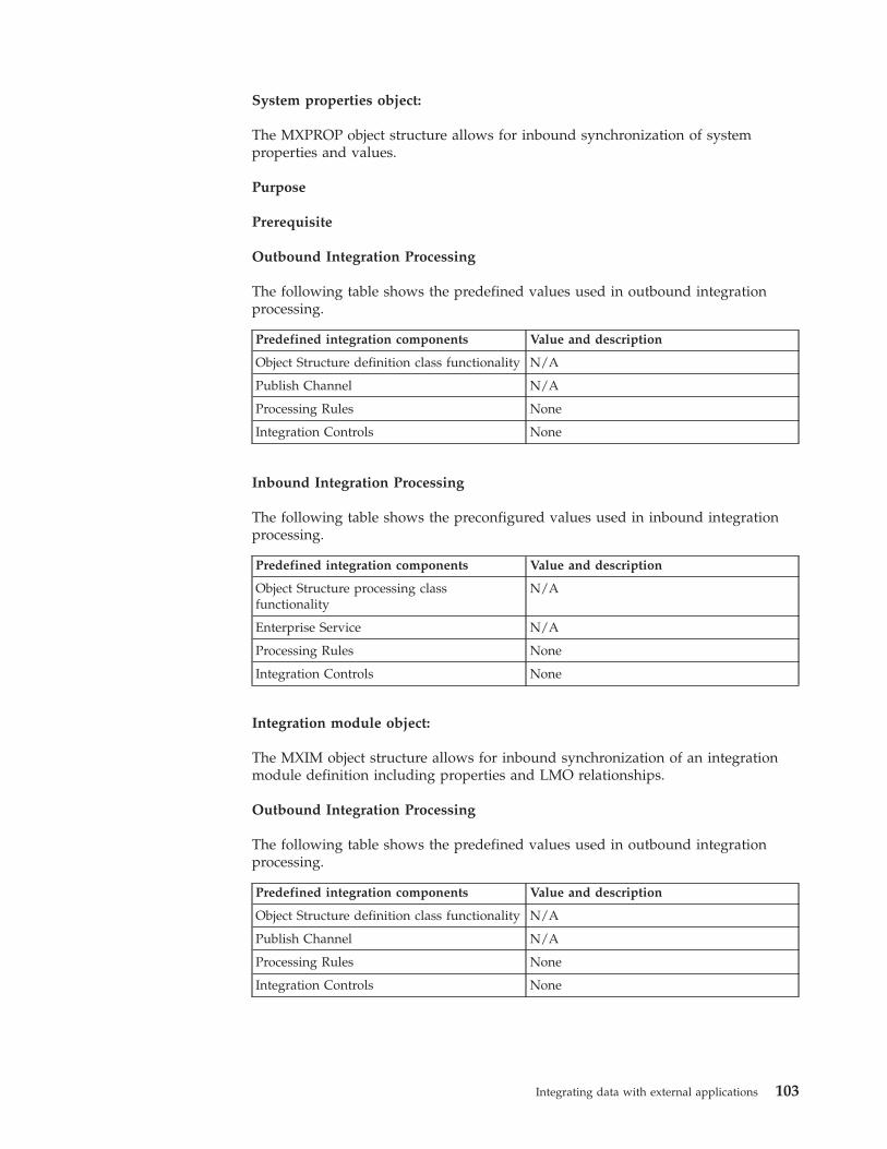
System properties object:
The MXPROP object structure allows for inbound synchronization of systemproperties and values.
Purpose
Prerequisite
Outbound Integration Processing
The following table shows the predefined values used in outbound integrationprocessing.
Predefined integration components Value and description
Object Structure definition class functionality N/A
Publish Channel N/A
Processing Rules None
Integration Controls None
Inbound Integration Processing
The following table shows the preconfigured values used in inbound integrationprocessing.
Predefined integration components Value and description
Object Structure processing classfunctionality
N/A
Enterprise Service N/A
Processing Rules None
Integration Controls None
Integration module object:
The MXIM object structure allows for inbound synchronization of an integrationmodule definition including properties and LMO relationships.
Outbound Integration Processing
The following table shows the predefined values used in outbound integrationprocessing.
Predefined integration components Value and description
Object Structure definition class functionality N/A
Publish Channel N/A
Processing Rules None
Integration Controls None
Integrating data with external applications 103
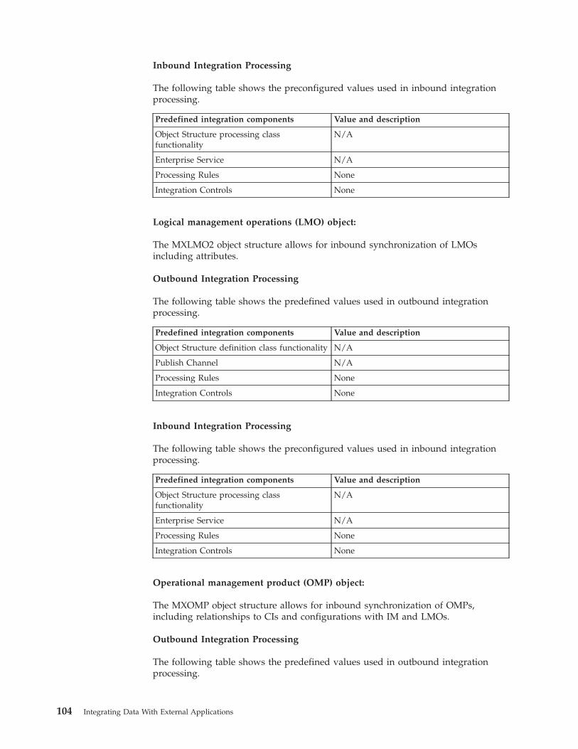
Inbound Integration Processing
The following table shows the preconfigured values used in inbound integrationprocessing.
Predefined integration components Value and description
Object Structure processing classfunctionality
N/A
Enterprise Service N/A
Processing Rules None
Integration Controls None
Logical management operations (LMO) object:
The MXLMO2 object structure allows for inbound synchronization of LMOsincluding attributes.
Outbound Integration Processing
The following table shows the predefined values used in outbound integrationprocessing.
Predefined integration components Value and description
Object Structure definition class functionality N/A
Publish Channel N/A
Processing Rules None
Integration Controls None
Inbound Integration Processing
The following table shows the preconfigured values used in inbound integrationprocessing.
Predefined integration components Value and description
Object Structure processing classfunctionality
N/A
Enterprise Service N/A
Processing Rules None
Integration Controls None
Operational management product (OMP) object:
The MXOMP object structure allows for inbound synchronization of OMPs,including relationships to CIs and configurations with IM and LMOs.
Outbound Integration Processing
The following table shows the predefined values used in outbound integrationprocessing.
104 Integrating Data With External Applications
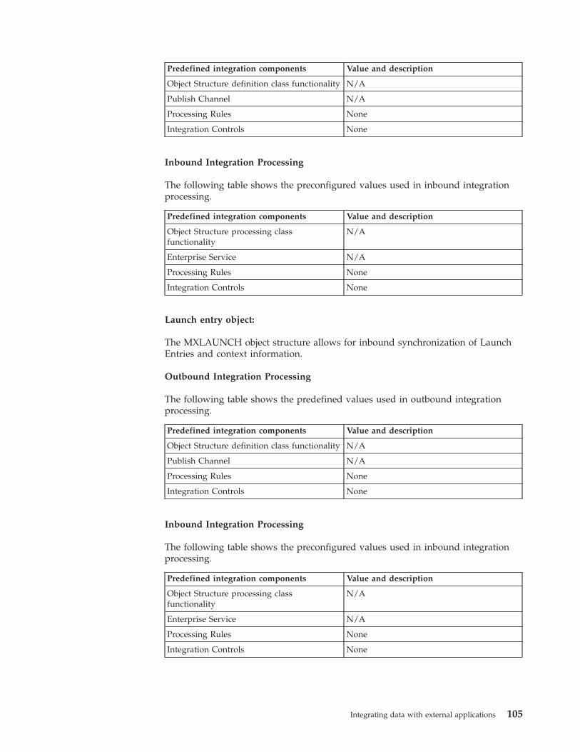
Predefined integration components Value and description
Object Structure definition class functionality N/A
Publish Channel N/A
Processing Rules None
Integration Controls None
Inbound Integration Processing
The following table shows the preconfigured values used in inbound integrationprocessing.
Predefined integration components Value and description
Object Structure processing classfunctionality
N/A
Enterprise Service N/A
Processing Rules None
Integration Controls None
Launch entry object:
The MXLAUNCH object structure allows for inbound synchronization of LaunchEntries and context information.
Outbound Integration Processing
The following table shows the predefined values used in outbound integrationprocessing.
Predefined integration components Value and description
Object Structure definition class functionality N/A
Publish Channel N/A
Processing Rules None
Integration Controls None
Inbound Integration Processing
The following table shows the preconfigured values used in inbound integrationprocessing.
Predefined integration components Value and description
Object Structure processing classfunctionality
N/A
Enterprise Service N/A
Processing Rules None
Integration Controls None
Integrating data with external applications 105

Data loading orderWhen you use the integration framework to load multiple sets of data into theapplication database, you must maintain the dependencies so that the data isloaded correctly. Use the following sequence of predefined object structures as aguide to determine the order in which you load the data.
Object structuresMXGLCOMPMXCOAMXVENDORMSTRMXVENDORMXPERSONMXPERUSERMXCRAFTMXLABORMXSTORELOCMXCLASSIFICATIONMXITEMMXINVENTORYMXINVBALMXINVVENDORMXSERVITEMMXPROJMXASSETMXWOMXWODETAILMXWOHIERMXINVRESMXEMPACTMXINVISSUEMXGLTXNMXTOOLITEMMXPCMXMETERDATAMXPRMXPOMXRECEIPTMXRCVROTITMMXINVOICE
System object structuresMXINTOBJECTMXIFACECONTROLMXENTSRVMXIFACEOUTMXENDPOINT
106 Integrating Data With External Applications
MXQUEUEMXEXTSYSTEMMXIFACEINVOKEMXIMMXLMO2MXOMPMXLAUNCHMXMESSAGEMXOBJECTCFGMXDOMAINMXCTEMPLATEMXACTIONMXPROP
Integration data processingYou can configure integration components in different ways to meet yourintegration requirements. You can integrate with multiple external applications,and each application requires a different integration approach that is based on theintegration support that is provided by that application.
Planning to process data for integrationBefore you initiate an integration transaction, you must decide which integrationcomponents to use. You must also plan how to implement these components sothat you can achieve a successful integration with the external destination for yourintegration.
The choice of the components that you use and how you implement them is oftendetermined by the external application that you are integrating with. These choicesinclude the following considerations:
Data typeDefine the data, for example work orders and person data. When defined,determine whether there are predefined object structures to support eachset of data or must you create more object structures.
DirectionFor each set of data, which direction will the integration scenarioimplement, sending outbound transactions, receiving inbound transactions,or both? The direction of the integration can vary for each set of data.
Message exchangeThis factor depends on the capabilities of the external application andoptions can include integrating data by using files (XML or flat), callingweb services, and posting XML over HTTP. The method of exchangingdata and how often that occurs can vary for each set of data.
CustomizationAs data is exchanged, is customization within the application needed totransform message content or to apply integration business rules? Ifcustomization is required, does it use integration framework capabilitiessuch as Java exit classes, automation scripts, XSL maps, or processing rules,or is customization implemented in the external application?
Integrating data with external applications 107
Depending upon the answers to these questions, you need different types ofcomponent and API configurations, which can include:v Object structuresv Publish channels and invocation channelsv Enterprise servicesv Object structure services, enterprise services, and standard servicesv Web servicesv REST and OSLC APIsv External systemsv Endpoints
Inbound data processingThe integration framework supports asynchronous and synchronous processing ofinbound integration messages with the following types of service; object structures,enterprise services, or standard services.
For asynchronous processing, the external system establishes and maintains aconnection until the message is passed into a JMS queue. For synchronousprocessing, the external system establishes maintains a connection until messageprocessing is complete.
Asynchronous processing of inbound messagesDuring asynchronous processing of inbound messages, an external application callsan enterprise service and maintains a connection until the message is saved to aJMS queue and the connection ends. If an error occurs during the save of themessage to the queue, the external application is responsible for reprocessing themessage.
Asynchronous processing is managed by sequential or continuous JMS queues.Processing in a sequential queue guarantees the order of delivery of messages,based on a first in, first out order. Processing in a continuous queue deliversmessages in any order.
You can use enterprise services to support the following transactions:v Importing data from a flat file or an XML filev Loading data from interface tablesv Receiving an XML message from an HTTP POST requestv Calling a web service that is configured to use a JMS queuev Calling an EJBv Using a direct JMS connection
All of these options support the use of an enterprise service, when the integrationmessage is passed into a JMS queue. When the message is in the queue, a separateprocess that uses a cron task or a message-driven bean (MDB) picks up themessage from the queue. The message is then processed through the enterpriseservice layer, the related object structure layer, and the business objects areupdated. Because messages are processed through a JMS queue, no response issent to the application that called the service and the Query operation is notsupported in this processing model.
108 Integrating Data With External Applications
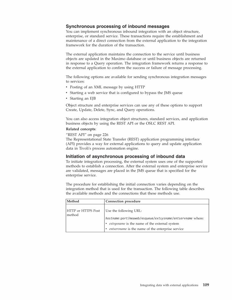
Synchronous processing of inbound messagesYou can implement synchronous inbound integration with an object structure,enterprise, or standard service. These transactions require the establishment andmaintenance of a direct connection from the external application to the integrationframework for the duration of the transaction.
The external application maintains the connection to the service until businessobjects are updated in the Maximo database or until business objects are returnedin response to a Query operation. The integration framework returns a response tothe external application to confirm the success or failure of message processing.
The following options are available for sending synchronous integration messagesto services:v Posting of an XML message by using HTTPv Starting a web service that is configured to bypass the JMS queuev Starting an EJB
Object structure and enterprise services can use any of these options to supportCreate, Update, Delete, Sync, and Query operations.
You can also access integration object structures, standard services, and applicationbusiness objects by using the REST API or the OSLC REST API.Related concepts:“REST API” on page 226The Representational State Transfer (REST) application programming interface(API) provides a way for external applications to query and update applicationdata in Tivoli's process automation engine.
Initiation of asynchronous processing of inbound dataTo initiate integration processing, the external system uses one of the supportedmethods to establish a connection. After the external system and enterprise serviceare validated, messages are placed in the JMS queue that is specified for theenterprise service.
The procedure for establishing the initial connection varies depending on theintegration method that is used for the transaction. The following table describesthe available methods and the connections that these methods use.
Method Connection procedure
HTTP or HTTPS Postmethod
Use the following URL:
hostname:port/meaweb/esqueue/extsysname/entservname where:
v extsysname is the name of the external system
v entservname is the name of the enterprise service
Integrating data with external applications 109
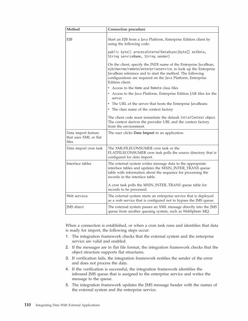
Method Connection procedure
EJB Start an EJB from a Java Platform, Enterprise Edition client byusing the following code:
public byte{} processExternalDataAsync(byte[] extData,String serviceName, String sender)
On the client, specify the JNDI name of the Enterprise JavaBean,ejb/maximo/remote/enterpriseservice, to look up the EnterpriseJavaBean reference and to start the method. The followingconfigurations are required on the Java Platform, EnterpriseEdition client:
v Access to the Home and Remote class files
v Access to the Java Platform, Enterprise Edition JAR files for theserver
v The URL of the server that hosts the Enterprise JavaBeans
v The class name of the context factory
The client code must instantiate the default IntialContext object.The context derives the provider URL and the context factoryfrom the environment.
Data import featurethat uses XML or flatfiles
The user clicks Data Import in an application.
Data import cron task The XMLFILECONSUMER cron task or theFLATFILECONSUMER cron task polls the source directory that isconfigured for data import.
Interface tables The external system writes message data to the appropriateinterface tables and updates the MXIN_INTER_TRANS queuetable with information about the sequence for processing therecords in the interface table.
A cron task polls the MXIN_INTER_TRANS queue table forrecords to be processed.
Web services The external system starts an enterprise service that is deployedas a web service that is configured not to bypass the JMS queue.
JMS direct The external system passes an XML message directly into the JMSqueue from another queuing system, such as WebSphere MQ.
When a connection is established, or when a cron task runs and identifies that datais ready for import, the following steps occur:1. The integration framework checks that the external system and the enterprise
service are valid and enabled.2. If the messages are in flat file format, the integration framework checks that the
object structure supports flat structures.3. If verification fails, the integration framework notifies the sender of the error
and does not process the data.4. If the verification is successful, the integration framework identifies the
inbound JMS queue that is assigned to the enterprise service and writes themessage to the queue.
5. The integration framework updates the JMS message header with the names ofthe external system and the enterprise service.
110 Integrating Data With External Applications
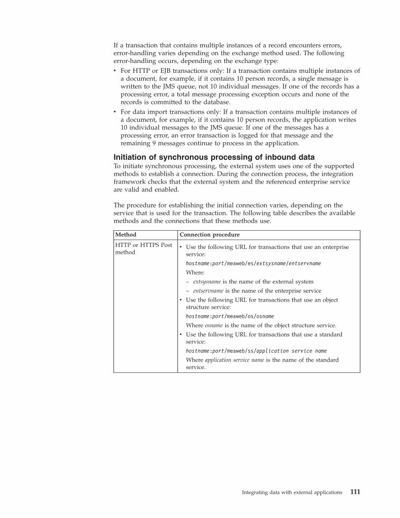
If a transaction that contains multiple instances of a record encounters errors,error-handling varies depending on the exchange method used. The followingerror-handling occurs, depending on the exchange type:v For HTTP or EJB transactions only: If a transaction contains multiple instances of
a document, for example, if it contains 10 person records, a single message iswritten to the JMS queue, not 10 individual messages. If one of the records has aprocessing error, a total message processing exception occurs and none of therecords is committed to the database.
v For data import transactions only: If a transaction contains multiple instances ofa document, for example, if it contains 10 person records, the application writes10 individual messages to the JMS queue. If one of the messages has aprocessing error, an error transaction is logged for that message and theremaining 9 messages continue to process in the application.
Initiation of synchronous processing of inbound dataTo initiate synchronous processing, the external system uses one of the supportedmethods to establish a connection. During the connection process, the integrationframework checks that the external system and the referenced enterprise serviceare valid and enabled.
The procedure for establishing the initial connection varies, depending on theservice that is used for the transaction. The following table describes the availablemethods and the connections that these methods use.
Method Connection procedure
HTTP or HTTPS Postmethod
v Use the following URL for transactions that use an enterpriseservice:
hostname:port/meaweb/es/extsysname/entservname
Where:
– extsysname is the name of the external system
– entservname is the name of the enterprise service
v Use the following URL for transactions that use an objectstructure service:
hostname:port/meaweb/os/osname
Where osname is the name of the object structure service.
v Use the following URL for transactions that use a standardservice:
hostname:port/meaweb/ss/application service name
Where application service name is the name of the standardservice.
Integrating data with external applications 111
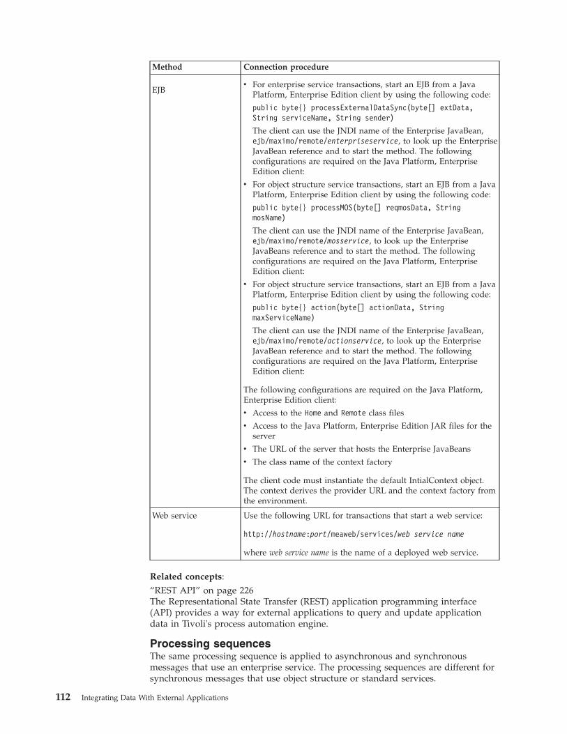
Method Connection procedure
EJBv For enterprise service transactions, start an EJB from a Java
Platform, Enterprise Edition client by using the following code:
public byte{} processExternalDataSync(byte[] extData,String serviceName, String sender)
The client can use the JNDI name of the Enterprise JavaBean,ejb/maximo/remote/enterpriseservice, to look up the EnterpriseJavaBean reference and to start the method. The followingconfigurations are required on the Java Platform, EnterpriseEdition client:
v For object structure service transactions, start an EJB from a JavaPlatform, Enterprise Edition client by using the following code:
public byte{} processMOS(byte[] reqmosData, StringmosName)
The client can use the JNDI name of the Enterprise JavaBean,ejb/maximo/remote/mosservice, to look up the EnterpriseJavaBeans reference and to start the method. The followingconfigurations are required on the Java Platform, EnterpriseEdition client:
v For object structure service transactions, start an EJB from a JavaPlatform, Enterprise Edition client by using the following code:
public byte{} action(byte[] actionData, StringmaxServiceName)
The client can use the JNDI name of the Enterprise JavaBean,ejb/maximo/remote/actionservice, to look up the EnterpriseJavaBean reference and to start the method. The followingconfigurations are required on the Java Platform, EnterpriseEdition client:
The following configurations are required on the Java Platform,Enterprise Edition client:
v Access to the Home and Remote class files
v Access to the Java Platform, Enterprise Edition JAR files for theserver
v The URL of the server that hosts the Enterprise JavaBeans
v The class name of the context factory
The client code must instantiate the default IntialContext object.The context derives the provider URL and the context factory fromthe environment.
Web service Use the following URL for transactions that start a web service:
http://hostname:port/meaweb/services/web service name
where web service name is the name of a deployed web service.
Related concepts:“REST API” on page 226The Representational State Transfer (REST) application programming interface(API) provides a way for external applications to query and update applicationdata in Tivoli's process automation engine.
Processing sequencesThe same processing sequence is applied to asynchronous and synchronousmessages that use an enterprise service. The processing sequences are different forsynchronous messages that use object structure or standard services.
112 Integrating Data With External Applications
Enterprise service processing sequences:
An enterprise service message processes through a number of layers to query andupdate business object data. You can use these processing layers to customize andcontrol processing to satisfy the integration requirements with the externalapplication.
For asynchronous processing, the data can originate from the following exchangemethods:v Interface tablesv HTTP Post of an XML messagev Starting a web service that is configured to use a JMS queuev Starting an EJBv Direct JMS connectionv Data import of a flat file or an XML file
For synchronous processing, the data can originate from the following exchangemethods:v HTTP Post of an XML message (HTTP)v Starting a web service that is configured to use a JMS queuev Starting an EJB
The same processing sequence applies for asynchronous and synchronousprocessing.
Enterprise service processing occurs in the following sequence:1. The external system calls the enterprise service.2. Custom processing can occur at several points during the processing of
enterprise services. You can run custom Java classes or automation scripts tomanipulate the message data or you can apply an XSL map. Custom processingoccurs in the following order:a. If a preprocessing method is defined in a user exit class, this method is
applied first.b. If an external exit class is specified, this processing is applied.c. If a postprocessing method is defined in a user exit class, this method is
applied.d. If an XSL map is specified for the enterprise service, the map is applied to
convert enterprise service format to object structure format.
At this point in the processing, the message must match the format of theobject structure that is associated with the enterprise service.
3. Object structure processing occurs in the following order:a. You can run custom Java classes or automation scripts to manipulate data
during object structure processing.b. If processing rules are configured for the object structure, these rules are run
next.c. If processing rules result in the multiplication of data for sites or
organizations, the object structure message is duplicated for the additionalsites or organizations.
d. Objects are created and object processing starts.4. Object processing occurs in the following order:
Integrating data with external applications 113
a. If a preprocessing method is defined in a user exit class, this method isapplied.
b. If an external exit class is specified, this processing is applied.c. If a postprocessing method is defined in a user exit class, this method is
applied.d. The business objects are processed, and data is saved to the database.
5. For synchronous transactions only, for Create, Update, Delete, and Syncoperations, the enterprise service provides a response to the starting applicationthat includes the following information:v Indicates whether the message was processed successfully.v The value of the internal ID column of the main object, regardless of whether
the column is part of the primary key of the main object.v The values of the primary key fields of the main object.v The values of any alternate key fields for the main object, which is
configured for the object or for the object structure.6. For synchronous transactions only, for Query operations, the entire object
structure is returned. You can run custom Java classes or automation scripts tomanipulate the response data, or you can apply an XSL map.
Synchronous integration with an object structure service:
An object structure service is accessible by using HTTP Post, EJB, and web serviceinvocation methods to receive synchronous object structure service messages. Theoperations Create, Update, Delete, Sync, and Query are supported.
Integration processing that is based on an object structure service occurs in thefollowing sequence:1. The external system uses one of the following invocation methods to initiate
communication with the integration framework:v HTTP invocationv EJB invocationv Web service invocation
2. The integration framework receives the inbound message that identifies theobject structure that is associated with the message
3. The integration framework builds the objects, based on the object structure andthe content of the inbound message.
4. The integration framework applies any predefined logic to the object structure.5. Objects are processed and data is committed to the database if the message
contains an update operation, or the data is returned to the requester if themessage contains a query operation.
6. If a processing error occurs, the response with an error message is returned tothe caller of the service.
Synchronous integration with a standard service:
A standard service is accessible by using HTTP Post, EJB, and web serviceinvocation methods to receive synchronous standard service messages.
Integration processing that is based on a standard service occurs in the followingsequence:
114 Integrating Data With External Applications
1. The external system uses one of the following invocation methods to initiatecommunication with the integration framework:v HTTP invocationv EJB invocationv Web service invocation
2. The objects are passed to the system, and standard system processing isapplied.
Outbound data processingPublish channels provide asynchronous processing of outbound messages that donot require a response from the external system. For outbound messages thatrequire a response from the external system, you can use an invocation channel toprovide synchronous processing.
Asynchronous integration with a publish channelThe integration framework uses publish channels to process asynchronousoutbound messages. The sending of a publish channel message can be initiated byan object event, or you can use the data export feature to send publish channelmessages on demand.
Publish channels are configured for an object structure and can enable event-basedintegration when the main object of the object structure is updated. An updateoccurs, for example, when a user saves a record in an application or completes astage in a workflow process. When the main object of an object structure isupdated, an event is initiated to all publish channels that are associated with theobject structure and are configured to listen for events. Users can use the dataexport feature in the External Systems application to initiate publish channelmessages at any time.
When a publish channel message is initiated by an event or by data export, theintegration framework performs a sequence of tasks:1. Identifies the object structure and the component objects that are associated
with the publish channel.2. Constructs the object structure for the transaction and forms an XML message
that is based on the content of the objects.3. Applies any processing rules that are defined in the Publish Channels
application.4. If the publish channel is associated with multiple external systems, creates
copies of the object structure, one for each publish channel and external systemcombination.
5. If any custom processing Java classes, automation scripts, or an XSL map areassociated with the publish channel, processes them in the following order:a. Runs the event filter class, if one is provided.b. Runs the preprocessing method in the user exit processing class, if one is
provided.c. Runs a publish channel processing class, if one is provided.d. ,e. Runs the postprocessing method in the user exit class, if one is provided.f. Applies an XSL map, if one is provided.
6. Writes the XML message to the outbound queue specified for the externalsystem.
Integrating data with external applications 115
7. A cron task picks up the publish channel message and delivers it to theexternal system, which is based on the endpoint that is configured.
Publish channel processing overview:
The object structure that is configured for a publish channel provides the messagecontent of the channel. The external system determines how and where theintegration message is delivered. Within the publish channel layer there areoptional processing layers that support the transformation of message content andthe application of business rules.
Event-based integration:
A publish channel can initiate an integration message in response to the processingof a system transaction, such as the update of an object.
You can configure publish channels to listen to events that occur on the primaryobject of the related object structure by selecting the Enable Listener check box inthe Publish Channels application. When the main object of an object structure isupdated, a publish channel message sends the updated information to the externalsystem.
When an update to a child object initiates an update to the main object, thisinformation is also sent to the external system. However, some updates to a childobject do not initiate an update to the main object and, as a result, the updatedinformation is not sent to the external system. For example, if an object structure isconfigured to support an attachment as a child object, when the user adds anattachment, the external system is not notified of this event.
To propagate an event from a child object to the primary object of the objectstructure, in the Object Structures application,you use the AdvancedConfigurations action to configure event propagation. When you configure anobject structure to propagate events on child objects to the main object, the mainobject then sends the updated information to the external system.
If you configure event propagation for an object structure, you must monitormessage activity carefully, because the configuration can initiate more messagesthan the external system is designed to process. For child objects that haveembedded logic to update the parent object, this configuration has no impact interms of enabling or disabling the event propagation from the child to the parentobject.
Data export feature:
The publish channel supports batch processing of integration data by using thedata export feature.
You initiate the data export feature by running a SQL query on the primary objectof an object structure, and the number of records to send. If the query is successful,the export starts.
You initiate the data export feature by providing a SQL WHERE clause on theprimary object of an object structure in the Data Export window. You can alsoconfigure the number of records to send. If the query is successful, the exportstarts and delivers the data based on the endpoint that is configured for thepublish channel.
116 Integrating Data With External Applications

Synchronous integration with an invocation channelThe integration framework uses invocation channels to process synchronousoutbound messages that require a confirmation or response content from theexternal application. The export is started by an action class that calls theinvocation channel.
Sending an invocation channel message is initiated by an action Java class that iscoded to start the channel. Invocation channels are used, for example, to call anexternal application to validate data, to start a process on an external application,or to retrieve data. An invocation channel can be triggered by a user interfacecontrol that is configured to call the action class that starts the channel.
When an invocation channel message is started by an action class, the integrationframework performs a sequence of tasks:1. Identifies the object structure that is associated with each invocation channel
and identifies the component objects.2. Constructs the object structure for the transaction and forms an XML message
that is based on the content of the objects.3. If any custom processing Java classes, automation scripts, or an XSL map are
associated with the invocation channel request, processes them in the followingorder:a. Runs the preprocessing method in the request user exit processing class, if
one is provided.b. Runs an invocation channel request processing class, if one is provided.c. Runs the postprocessing method in the request user exit class, if one is
provided.d. Applies an XSL map, if one is provided.
4. Writes the XML message to the destination that is specified by the endpoint.5. The endpoint handler specifies the transport mechanism to use.6. When the response is received from the end point, if any custom Java classes,
automation scripts, or XSL maps are associated with the response, processesthem in the following order:a. Runs the preprocessing method in the response user exit processing class, if
one is provided.b. Runs an invocation channel response processing class, if one is provided.c. Runs the postprocessing method in the response user exit class, if one is
provided.d. Applies an XSL map, if one is provided.
7. Objects are built from the data in the response object structure and are passedto the system where standard processing is applied.
8. If all the objects that are created from the response object structure processsuccessfully, they are committed to the database.
The response content can be managed by the invoker based on integrationrequirements, for example to update business object data or display the response toa user. A default action class is provided that you can use or extend to implementan invocation channel integration.
Integrating data with external applications 117
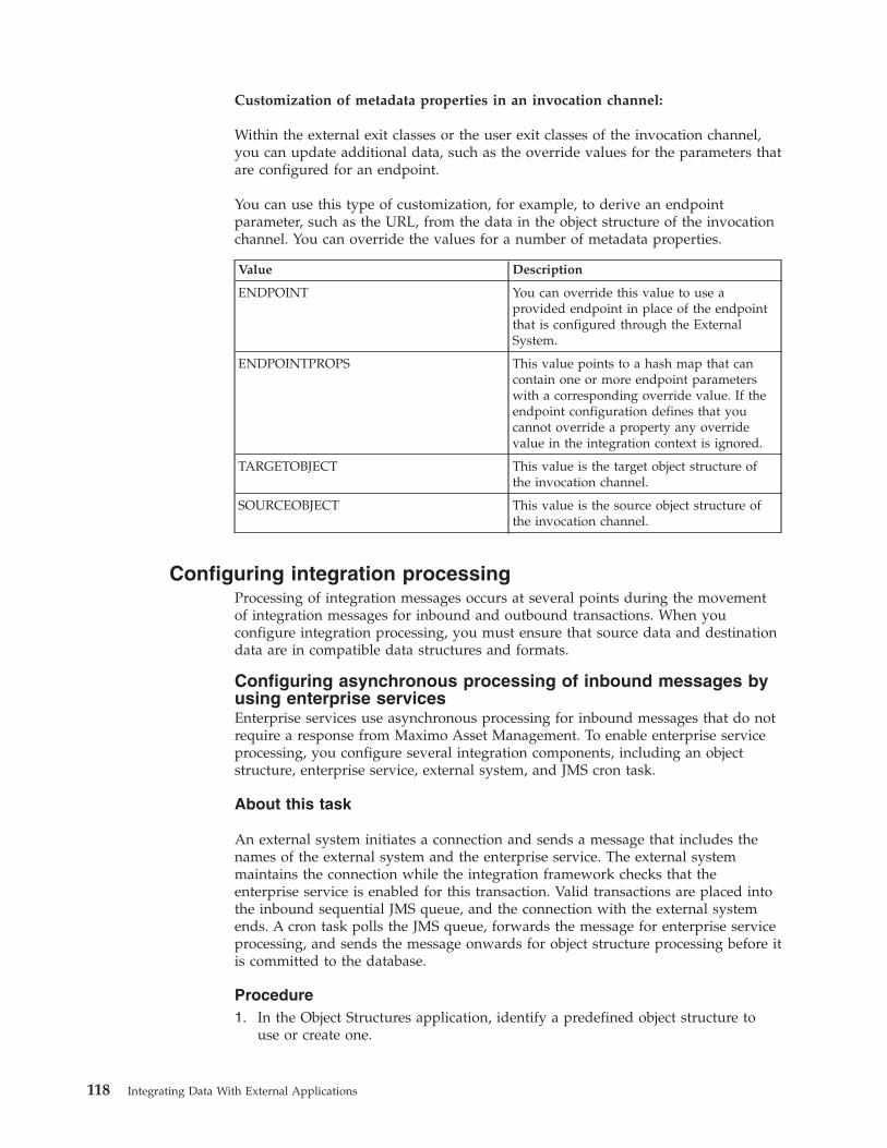
Customization of metadata properties in an invocation channel:
Within the external exit classes or the user exit classes of the invocation channel,you can update additional data, such as the override values for the parameters thatare configured for an endpoint.
You can use this type of customization, for example, to derive an endpointparameter, such as the URL, from the data in the object structure of the invocationchannel. You can override the values for a number of metadata properties.
Value Description
ENDPOINT You can override this value to use aprovided endpoint in place of the endpointthat is configured through the ExternalSystem.
ENDPOINTPROPS This value points to a hash map that cancontain one or more endpoint parameterswith a corresponding override value. If theendpoint configuration defines that youcannot override a property any overridevalue in the integration context is ignored.
TARGETOBJECT This value is the target object structure ofthe invocation channel.
SOURCEOBJECT This value is the source object structure ofthe invocation channel.
Configuring integration processingProcessing of integration messages occurs at several points during the movementof integration messages for inbound and outbound transactions. When youconfigure integration processing, you must ensure that source data and destinationdata are in compatible data structures and formats.
Configuring asynchronous processing of inbound messages byusing enterprise servicesEnterprise services use asynchronous processing for inbound messages that do notrequire a response from Maximo Asset Management. To enable enterprise serviceprocessing, you configure several integration components, including an objectstructure, enterprise service, external system, and JMS cron task.
About this task
An external system initiates a connection and sends a message that includes thenames of the external system and the enterprise service. The external systemmaintains the connection while the integration framework checks that theenterprise service is enabled for this transaction. Valid transactions are placed intothe inbound sequential JMS queue, and the connection with the external systemends. A cron task polls the JMS queue, forwards the message for enterprise serviceprocessing, and sends the message onwards for object structure processing before itis committed to the database.
Procedure1. In the Object Structures application, identify a predefined object structure to
use or create one.
118 Integrating Data With External Applications
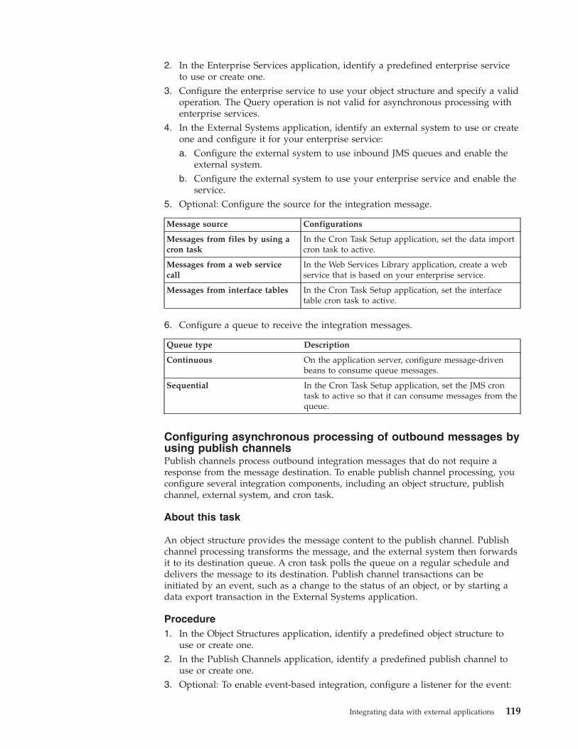
2. In the Enterprise Services application, identify a predefined enterprise serviceto use or create one.
3. Configure the enterprise service to use your object structure and specify a validoperation. The Query operation is not valid for asynchronous processing withenterprise services.
4. In the External Systems application, identify an external system to use or createone and configure it for your enterprise service:a. Configure the external system to use inbound JMS queues and enable the
external system.b. Configure the external system to use your enterprise service and enable the
service.5. Optional: Configure the source for the integration message.
Message source Configurations
Messages from files by using acron task
In the Cron Task Setup application, set the data importcron task to active.
Messages from a web servicecall
In the Web Services Library application, create a webservice that is based on your enterprise service.
Messages from interface tables In the Cron Task Setup application, set the interfacetable cron task to active.
6. Configure a queue to receive the integration messages.
Queue type Description
Continuous On the application server, configure message-drivenbeans to consume queue messages.
Sequential In the Cron Task Setup application, set the JMS crontask to active so that it can consume messages from thequeue.
Configuring asynchronous processing of outbound messages byusing publish channelsPublish channels process outbound integration messages that do not require aresponse from the message destination. To enable publish channel processing, youconfigure several integration components, including an object structure, publishchannel, external system, and cron task.
About this task
An object structure provides the message content to the publish channel. Publishchannel processing transforms the message, and the external system then forwardsit to its destination queue. A cron task polls the queue on a regular schedule anddelivers the message to its destination. Publish channel transactions can beinitiated by an event, such as a change to the status of an object, or by starting adata export transaction in the External Systems application.
Procedure1. In the Object Structures application, identify a predefined object structure to
use or create one.2. In the Publish Channels application, identify a predefined publish channel to
use or create one.3. Optional: To enable event-based integration, configure a listener for the event:
Integrating data with external applications 119
a. In the Publish Channels application, select the Enable Publish ChannelListener action. If the listener is enabled, when the primary object of theobject structure is updated, publish channel transactions are initiated.
b. If you want events on child objects to start publish channel transactions, inthe Object Structures application, select the Advanced Configurationsaction and configure event propagation.
4. Optional: In the Publish Channels application, review the processing rules andadd or change rules as necessary. Processing rules are run in the orderindicated in the Sequence field. If you change the sequence values, rules run ina different order, which can have unintended results.
5. Optional: Specify any automation scripts , custom Java class files, or XSL mapsto provide custom logic during the transformation process.
6. In the External Systems application, add the publish channel to the externalsystem and specify the filepath to the outbound sequential JMS queue.
7. In the Cron Task Setup application, enable the SEQOUT instance of theJMSQSEQCONSUMER cron task. The cron task delivers messages from the JMSqueue to their destinations in the same order as the messages are received intothe queue.
Rule-based customizationYou can use processing rules to change the behavior of predefined integrationprocessing without writing Java classes, automation scripts, or XSL maps. You canimplement processing rules only on publish channels or on enterprise services.
Processing rules can access and evaluate the values in XML and object fields, objectsets, and integration and system controls. Processing rules also can change thevalues in XML and object fields, or stop or skip processing all or part of a message.
Rule definitions for objects and recordsAn object structure consists of one or more object records. When an object iscreated, the object fields are populated from the corresponding record fields beforestandard application processing is applied.
During outbound processing, the original object is populated with the record fieldsfrom the corresponding fields. Except for certain generic integration fields, systemobjects are not updated in outbound messages.
Use the following guidelines to apply a rule to an object structure record or to anobject:v For outbound processing, you can apply processing rules to object structure
records only.v For inbound processing, you can apply processing rules to object structure
records or to objects.– If an inbound rule changes the key field value of an object, apply rules to the
object structure record.– If an inbound rule does not evaluate or manipulate an object or object set,
apply rules to the object structure record.– If an inbound rule evaluates or manipulates a user-defined field, apply rules
to the object structure record.– If an inbound rule evaluates or manipulates an object or object field, apply
rules to the object.
120 Integrating Data With External Applications
Apply all rules for enterprise services to either objects or to object structurerecords. Avoid applying rules to both objects and object structure records. If youapply processing rules to both object structures and objects, the processing time forinbound transactions increases.
Processing rule definitionsA processing rule performs an action on a field in a record or object, or on therecord or object itself. To define a processing rule, in the service or channel usedfor the transaction, you can specify the record or object to which the rule applies.
Processing rule initiation:
For an outbound transaction, a business object event on the primary object of anobject structure initiates a processing rule. For an inbound transaction, the eventthat initiates a processing rule is identified by the value of the Action attribute onthe primary object of the inbound XML message.
When you configure publish channels and enterprise services, you specify whichevents to use to initiate each processing rule. You can apply a processing rule tothe primary record, a child record, or an object, but the event that initiates the rulemust be initiated on the primary object.
You can, for example, implement a Stop rule on the PERSON object that preventsusers from changing any attribute on the person record by identifying that the ruleapplies on update. With this configuration, users can create or delete personrecords but users cannot update person records.
For outbound transactions, in the Publish Channels application you can configureone or more of the following actions on the primary object to initiate the rule:v Insertv Deletev Update
When an outbound message is generated using the Data Export feature or by aprogrammatic call to the publish channel, all enabled processing rules are run,regardless of the event settings.
For inbound transactions, in the Enterprise Services application you can configureone or more of the following actions on the primary object to initiate the rule:v Addv Change or Replace (equivalent of Update)v Delete
You can set one of these values as the Action attribute of the primary object for theinbound transaction.
Processing rule actions:
A processing rule can act on an enterprise service or a publish channel as a whole.For example, a rule can bypass a message, or it can manipulate the value in a datafield within the message.
Three processing rule actions act on a service or channel message: stop, skip, andskip children. Four processing rule actions transform the value in a field within aservice or channel message: combine, split, set, and replace.
Integrating data with external applications 121
Message processing actions:
Message processing actions stop or skip an entire enterprise service or publishchannel message, or skip entire records within the message.
Skip action
The skip action bypasses a message that meets specified criteria. When a skipaction is applied to an inbound message, the message is not processed and iscleared from the inbound queue. When a skip action is applied to an outboundmessage, nothing is written to the queue and the message is not sent to an externalsystem. Skip processing does not generate an error, but the system log file isupdated with the rule that caused the skip action.
A skip action has some predefined rules. These rules look up integration controlvalues to ensure that outbound messages have a valid status before being sent tothe external system.
Stop action
The stop action halts the processing of a message that meets specified criteria. Anoutbound message is rolled back and an error message is displayed. For inboundtransactions, the message remains in the inbound JMS queue. If the error was theresult of a synchronous invocation of the enterprise service, the calling program isnotified about the error.
Predefined rules are not provided with a stop action. This option is a utility forusers to customize the behavior of a service or channel.
When possible, use the skip action rather than the stop action for inboundenterprise services. The stop action results in a processing error and the messageremains in the inbound queue or the initiator receives an error response. Theseresults do not occur when you use the skip action.
If a processing rule with a stop action is applied to a publish channel that isgenerated by the Data Export feature, the stop action is treated as a skip action. Ifthe stop action evaluates as true, the message is skipped.
Skip children action
You can apply the skip children action only to outbound messages in a publishchannel. Apply the processing rule on the record or object whose child levelrecords are skipped.
If the person structure has the person object and child objects of phone and email,you can use the skip children action on a person to strip the phone and email datafrom the message. Use the skip children action when a status change occurs andthe external system does not need the accompanying phone and email information.
Skip record action
You can apply the skip record action only to outbound messages in a publishchannel. The skip record action deletes a record or object that contains yourapplied rule. Apply the processing rule on the record or object, and all of childrecords and objects, that you want to skip.
122 Integrating Data With External Applications
If the person object structure has a person object and a child object of phone, youcan use the skip record action to strip a specific phone record from the message.Use the skip record action, for example, when you want to send the work phonenumber but not the home phone number for a person. The skip record rule needsa condition that identifies a home phone record to ensure that the record isskipped.
Field transformation actions:
Apply the field transformation rule to a record or object that contains the field tobe transformed. A field transformation rule can be applied to a single field ormultiple fields in the selected record.
Set action
The set action writes a value to a specified data field. When you define the rule,you specify the data to be set and the source of the new value. Indicate whetherthe rule always writes the new value to the target field or writes the new valueonly when the field is null (the default action). You can use this action to initializethe value in a data field. If the rule always writes the new value to the target field,any existing value in the field is overwritten.
The source can be one of the following values:v A value integration controlv A hard-coded valuev A system control (in the MAXVARS database table)v Another field in the specified record or objectv A field in a related object
Replace action
The replace action replaces a value in a data field with another value. When youdefine the rule, specify the data field that you want to update. The control that youuse must be a cross-reference control. You specify the name of a cross-referencecontrol that contains the original and replacement values for the data field.
Use this action when the database and the external system use different identifiersfor the same entity. You can, for example, replace the SITEID value in a publishchannel with an external PLANTID value, and replace the external PLANTIDvalue in an enterprise service with the SITEID value.
Combine action
The combine action concatenates values from multiple source fields into a singletarget field. When you define the rule, identify the target field and the sourcefields and the sequence in which the source data is to be written. The source datacan be a data field or an integration control that contains a data value. You canalso specify an integration control that contains the delimiter to separate thesegments in the target field.
Use this action in an enterprise service processing rule when a mismatch existsbetween the system definition and the external system definition of an entity. Anenterprise service processing rule can, for example, combine a vendor ID and avendor location field from an external system into the COMPANY field. A publish
Integrating data with external applications 123
channel processing rule can then use the split action to separate the combined fieldinto separate values when data is sent to the external system.
The source and target fields must be in the same object. This action alwaysoverwrites the existing value in the target field. Ensure that the source and targetfields are alphanumeric fields, or processing errors may occur.
Split action
The split action is the reverse of the combine action. The split action separates thevalue in one field into multiple fields. When you define the rule, you identify onesource field, one or more target fields, and how the rule processor identifiessegments of the source field.
The fields can have the following sources:v A field in the selected record or objectv An integration control that contains the delimiter that separates the segments in
the source field
The source and target fields must exist in the same object. This action alwaysoverwrites the existing value in the target fields. Ensure that the source and targetfields are alphanumeric fields, or processing errors might occur.
If you combined multiple fields in an inbound message, split the combined fieldinto individual fields in the outbound direction. There are two ways to identifyhow to split the field. You can specify the length of each segment of the sourcefield, or you can identify a delimiter that separates the segments.
If the field length of each segment of source data is constant, the rule processorbreaks up the source field from left to right, based on the field length, sequence,and values that you specify. For example, target field A with a character length of 6holds positions 1-6 of the source field. Target field B with a character length of 3holds positions 7-9 of the source field.
If the length of the source field segments is variable, but the source field contains adistinct delimiter that identifies the segments, use the separator option. Theseparator option identifies an integration control that defines the separator. Thesame separator must delimit all the segments. The rule processor parses the sourcefield from left to right. The processor looks for the delimiter, breaks up the stringinto multiple values, and moves each value into the designated target field.
Processing sequence:
Processing rules are applied sequentially for each record or object within an objectstructure, starting with the primary object and moving down to the child objects.
If you define multiple processing rules for a single record or object, you canmodify the default processing sequence. Your modification is especially importantif a rule depends on the successful result of an earlier rule. If a rule with a stop orskip action is successfully applied, no further checking occurs.
Conditions and evaluationsProcessing rules are applied conditionally. Any conditions must be met before theprocessing or action that is specified in the rule can be performed.
124 Integrating Data With External Applications
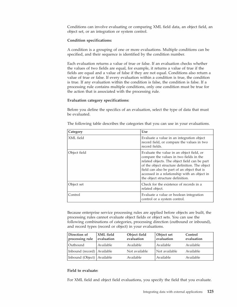
Conditions can involve evaluating or comparing XML field data, an object field, anobject set, or an integration or system control.
Condition specifications:
A condition is a grouping of one or more evaluations. Multiple conditions can bespecified, and their sequence is identified by the condition number.
Each evaluation returns a value of true or false. If an evaluation checks whetherthe values of two fields are equal, for example, it returns a value of true if thefields are equal and a value of false if they are not equal. Conditions also return avalue of true or false. If every evaluation within a condition is true, the conditionis true. If any evaluation within the condition is false, the condition is false. If aprocessing rule contains multiple conditions, only one condition must be true forthe action that is associated with the processing rule.
Evaluation category specifications:
Before you define the specifics of an evaluation, select the type of data that mustbe evaluated.
The following table describes the categories that you can use in your evaluations.
Category Use
XML field Evaluate a value in an integration objectrecord field, or compare the values in tworecord fields.
Object field Evaluate the value in an object field, orcompare the values in two fields in therelated objects. The object field can be partof the object structure definition. The objectfield can also be part of an object that isaccessed in a relationship with an object inthe object structure definition.
Object set Check for the existence of records in arelated object.
Control Evaluate a value or boolean integrationcontrol or a system control.
Because enterprise service processing rules are applied before objects are built, theprocessing rules cannot evaluate object fields or object sets. You can use thefollowing combinations of categories, processing direction (outbound or inbound),and record types (record or object) in your evaluations.
Direction ofprocessing rule
XML fieldevaluation
Object fieldevaluation
Object setevaluation
Controlevaluation
Outbound Available Available Available Available
Inbound (record) Available Not available Not available Available
Inbound (Object) Available Available Available Available
Field to evaluate:
For XML field and object field evaluations, you specify the field that you evaluate.
Integrating data with external applications 125
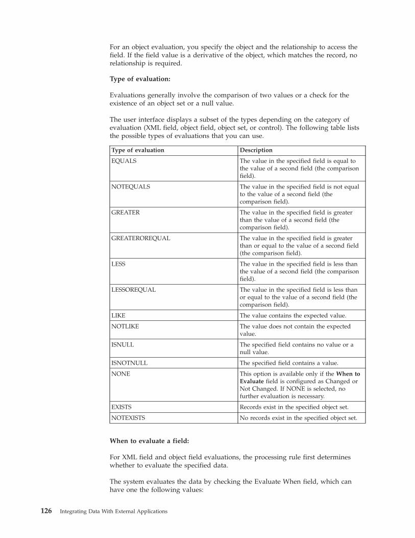
For an object evaluation, you specify the object and the relationship to access thefield. If the field value is a derivative of the object, which matches the record, norelationship is required.
Type of evaluation:
Evaluations generally involve the comparison of two values or a check for theexistence of an object set or a null value.
The user interface displays a subset of the types depending on the category ofevaluation (XML field, object field, object set, or control). The following table liststhe possible types of evaluations that you can use.
Type of evaluation Description
EQUALS The value in the specified field is equal tothe value of a second field (the comparisonfield).
NOTEQUALS The value in the specified field is not equalto the value of a second field (thecomparison field).
GREATER The value in the specified field is greaterthan the value of a second field (thecomparison field).
GREATEROREQUAL The value in the specified field is greaterthan or equal to the value of a second field(the comparison field).
LESS The value in the specified field is less thanthe value of a second field (the comparisonfield).
LESSOREQUAL The value in the specified field is less thanor equal to the value of a second field (thecomparison field).
LIKE The value contains the expected value.
NOTLIKE The value does not contain the expectedvalue.
ISNULL The specified field contains no value or anull value.
ISNOTNULL The specified field contains a value.
NONE This option is available only if the When toEvaluate field is configured as Changed orNot Changed. If NONE is selected, nofurther evaluation is necessary.
EXISTS Records exist in the specified object set.
NOTEXISTS No records exist in the specified object set.
When to evaluate a field:
For XML field and object field evaluations, the processing rule first determineswhether to evaluate the specified data.
The system evaluates the data by checking the Evaluate When field, which canhave one the following values:
126 Integrating Data With External Applications
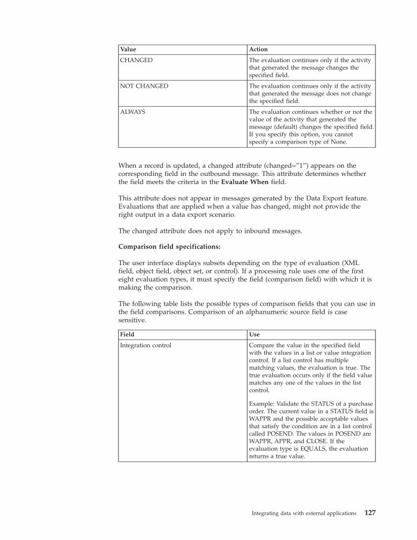
Value Action
CHANGED The evaluation continues only if the activitythat generated the message changes thespecified field.
NOT CHANGED The evaluation continues only if the activitythat generated the message does not changethe specified field.
ALWAYS The evaluation continues whether or not thevalue of the activity that generated themessage (default) changes the specified field.If you specify this option, you cannotspecify a comparison type of None.
When a record is updated, a changed attribute (changed=”1”) appears on thecorresponding field in the outbound message. This attribute determines whetherthe field meets the criteria in the Evaluate When field.
This attribute does not appear in messages generated by the Data Export feature.Evaluations that are applied when a value has changed, might not provide theright output in a data export scenario.
The changed attribute does not apply to inbound messages.
Comparison field specifications:
The user interface displays subsets depending on the type of evaluation (XMLfield, object field, object set, or control). If a processing rule uses one of the firsteight evaluation types, it must specify the field (comparison field) with which it ismaking the comparison.
The following table lists the possible types of comparison fields that you can use inthe field comparisons. Comparison of an alphanumeric source field is casesensitive.
Field Use
Integration control Compare the value in the specified fieldwith the values in a list or value integrationcontrol. If a list control has multiplematching values, the evaluation is true. Thetrue evaluation occurs only if the field valuematches any one of the values in the listcontrol.
Example: Validate the STATUS of a purchaseorder. The current value in a STATUS field isWAPPR and the possible acceptable valuesthat satisfy the condition are in a list controlcalled POSEND. The values in POSEND areWAPPR, APPR, and CLOSE. If theevaluation type is EQUALS, the evaluationreturns a true value.
Integrating data with external applications 127
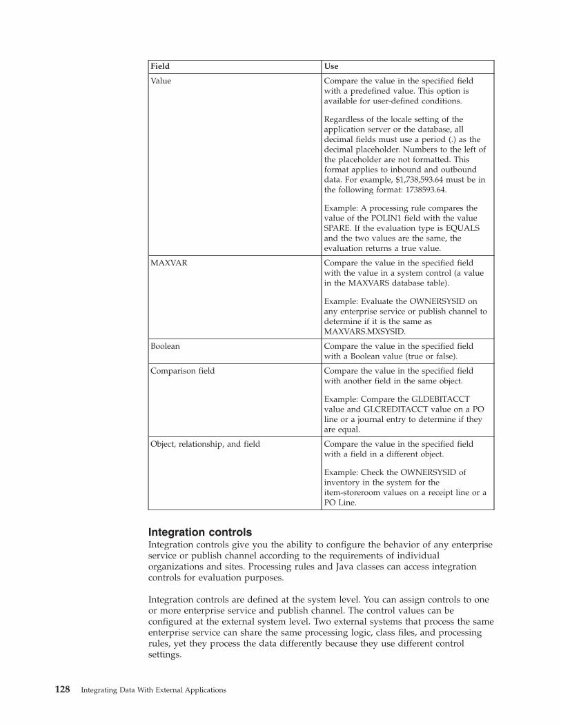
Field Use
Value Compare the value in the specified fieldwith a predefined value. This option isavailable for user-defined conditions.
Regardless of the locale setting of theapplication server or the database, alldecimal fields must use a period (.) as thedecimal placeholder. Numbers to the left ofthe placeholder are not formatted. Thisformat applies to inbound and outbounddata. For example, $1,738,593.64 must be inthe following format: 1738593.64.
Example: A processing rule compares thevalue of the POLIN1 field with the valueSPARE. If the evaluation type is EQUALSand the two values are the same, theevaluation returns a true value.
MAXVAR Compare the value in the specified fieldwith the value in a system control (a valuein the MAXVARS database table).
Example: Evaluate the OWNERSYSID onany enterprise service or publish channel todetermine if it is the same asMAXVARS.MXSYSID.
Boolean Compare the value in the specified fieldwith a Boolean value (true or false).
Comparison field Compare the value in the specified fieldwith another field in the same object.
Example: Compare the GLDEBITACCTvalue and GLCREDITACCT value on a POline or a journal entry to determine if theyare equal.
Object, relationship, and field Compare the value in the specified fieldwith a field in a different object.
Example: Check the OWNERSYSID ofinventory in the system for theitem-storeroom values on a receipt line or aPO Line.
Integration controlsIntegration controls give you the ability to configure the behavior of any enterpriseservice or publish channel according to the requirements of individualorganizations and sites. Processing rules and Java classes can access integrationcontrols for evaluation purposes.
Integration controls are defined at the system level. You can assign controls to oneor more enterprise service and publish channel. The control values can beconfigured at the external system level. Two external systems that process the sameenterprise service can share the same processing logic, class files, and processingrules, yet they process the data differently because they use different controlsettings.
128 Integrating Data With External Applications
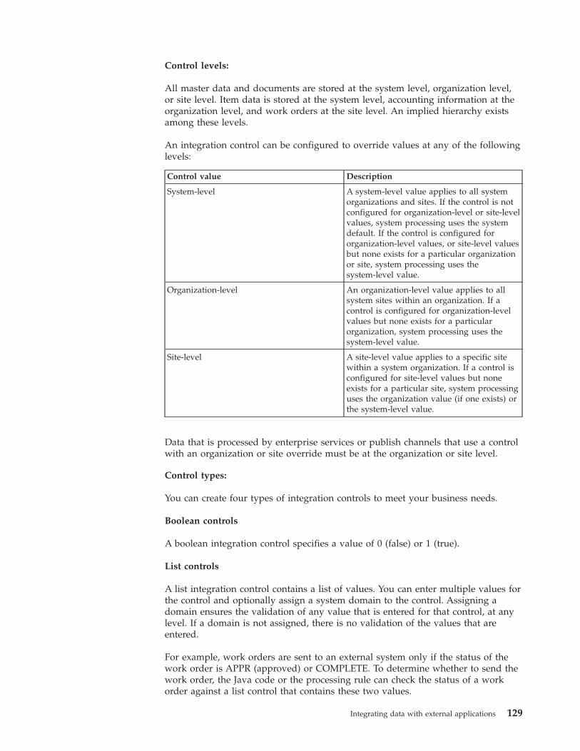
Control levels:
All master data and documents are stored at the system level, organization level,or site level. Item data is stored at the system level, accounting information at theorganization level, and work orders at the site level. An implied hierarchy existsamong these levels.
An integration control can be configured to override values at any of the followinglevels:
Control value Description
System-level A system-level value applies to all systemorganizations and sites. If the control is notconfigured for organization-level or site-levelvalues, system processing uses the systemdefault. If the control is configured fororganization-level values, or site-level valuesbut none exists for a particular organizationor site, system processing uses thesystem-level value.
Organization-level An organization-level value applies to allsystem sites within an organization. If acontrol is configured for organization-levelvalues but none exists for a particularorganization, system processing uses thesystem-level value.
Site-level A site-level value applies to a specific sitewithin a system organization. If a control isconfigured for site-level values but noneexists for a particular site, system processinguses the organization value (if one exists) orthe system-level value.
Data that is processed by enterprise services or publish channels that use a controlwith an organization or site override must be at the organization or site level.
Control types:
You can create four types of integration controls to meet your business needs.
Boolean controls
A boolean integration control specifies a value of 0 (false) or 1 (true).
List controls
A list integration control contains a list of values. You can enter multiple values forthe control and optionally assign a system domain to the control. Assigning adomain ensures the validation of any value that is entered for that control, at anylevel. If a domain is not assigned, there is no validation of the values that areentered.
For example, work orders are sent to an external system only if the status of thework order is APPR (approved) or COMPLETE. To determine whether to send thework order, the Java code or the processing rule can check the status of a workorder against a list control that contains these two values.
Integrating data with external applications 129
Value controls
A value integration control contains a single value. You can enter a single value forthe control and optionally assign a system domain to the control.
Cross-reference controls
A cross-reference control replaces one value with another. In a publish channel, asystem value is converted to an external system value. In an enterprise service, anexternal system value is converted to a system value. You can optionally assign asystem domain to a cross-reference control. If a domain is specified, any systemvalue that is specified for the control is validated against that domain. If a domainis not assigned, there is no validation of the values that are entered.
Cross-reference controls must have a one-to-one mapping between the systemvalue and the external system value. If two system values are associated with anexternal system value, or two external system values with a system value, aprocessing error occurs.
If you create the cross-reference control to function as a multiplication control onan enterprise service, one-to-many mappings can exist. A multiplication control is across-reference control that copies, or multiples, an inbound message for multipleorganizations or sites. A multiplication control has one external value and multiplesystem values.
Multiplication controls are always specific to the external system. You identify thecontrol as a multiplication control on the Enterprise Service tab in the EnterpriseServices application.
For example, the system sites correspond to external system business units, but thetwo systems use different values for these entities. A cross-reference control canperform the translation between the two values. A cross-reference control in anenterprise service can translate business unit EX001 to system site MX001. In apublish channel, the same control can translate MX001 to EX001.
Multiplication controls
A multiplication control can update the company in every organization in thesystem database. For example, use a multiplication control to update the companyin every organization within the system. Value updates occur when the systemreceives company data using an enterprise service.
New control creation:
Modifying control values at the external system level is generally sufficient tocustomize predefined enterprise service or publish channel processing. If newbusiness rules are implemented or a new publish channel and enterprise service isimplemented, a new control might be needed.
Use the following guidelines when you create new controls:v Control names must unique.v To use the controls as part of a processing rule, and to set a value at the external
system level, associate controls with a publish channel or enterprise service.
130 Integrating Data With External Applications
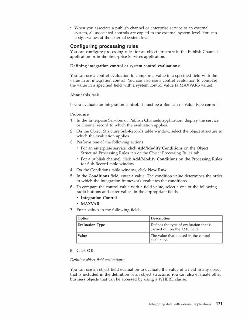
v When you associate a publish channel or enterprise service to an externalsystem, all associated controls are copied to the external system level. You canassign values at the external system level.
Configuring processing rulesYou can configure processing rules for an object structure in the Publish Channelsapplication or in the Enterprise Services application.
Defining integration control or system control evaluations:
You can use a control evaluation to compare a value in a specified field with thevalue in an integration control. You can also use a control evaluation to comparethe value in a specified field with a system control value (a MAXVARS value).
About this task
If you evaluate an integration control, it must be a Boolean or Value type control.
Procedure
1. In the Enterprise Services or Publish Channels application, display the serviceor channel record to which the evaluation applies.
2. On the Object Structure Sub-Records table window, select the object structure towhich the evaluation applies.
3. Perform one of the following actions:v For an enterprise service, click Add/Modify Conditions on the Object
Structure Processing Rules tab or the Object Processing Rules tab.v For a publish channel, click Add/Modify Conditions on the Processing Rules
for Sub-Record table window.4. On the Conditions table window, click New Row.5. In the Conditions field, enter a value. The condition value determines the order
in which the integration framework evaluates the conditions.6. To compare the control value with a field value, select a one of the following
radio buttons and enter values in the appropriate fields.v Integration Control
v MAXVAR
7. Enter values in the following fields:
Option Description
Evaluation Type Defines the type of evaluation that iscarried out on the XML field.
Value The value that is used in the controlevaluation.
8. Click OK.
Defining object field evaluations:
You can use an object field evaluation to evaluate the value of a field in any objectthat is included in the definition of an object structure. You can also evaluate otherbusiness objects that can be accessed by using a WHERE clause.
Integrating data with external applications 131
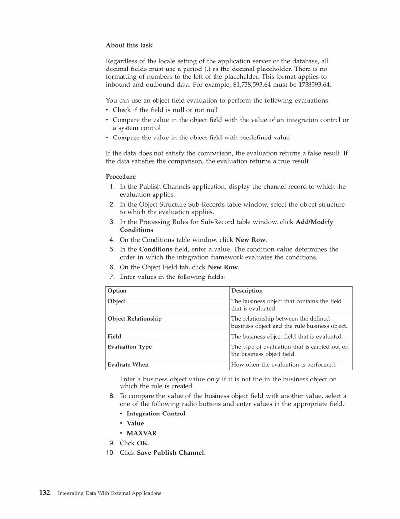
About this task
Regardless of the locale setting of the application server or the database, alldecimal fields must use a period (.) as the decimal placeholder. There is noformatting of numbers to the left of the placeholder. This format applies toinbound and outbound data. For example, $1,738,593.64 must be 1738593.64.
You can use an object field evaluation to perform the following evaluations:v Check if the field is null or not nullv Compare the value in the object field with the value of an integration control or
a system controlv Compare the value in the object field with predefined value
If the data does not satisfy the comparison, the evaluation returns a false result. Ifthe data satisfies the comparison, the evaluation returns a true result.
Procedure
1. In the Publish Channels application, display the channel record to which theevaluation applies.
2. In the Object Structure Sub-Records table window, select the object structureto which the evaluation applies.
3. In the Processing Rules for Sub-Record table window, click Add/ModifyConditions.
4. On the Conditions table window, click New Row.5. In the Conditions field, enter a value. The condition value determines the
order in which the integration framework evaluates the conditions.6. On the Object Field tab, click New Row.7. Enter values in the following fields:
Option Description
Object The business object that contains the fieldthat is evaluated.
Object Relationship The relationship between the definedbusiness object and the rule business object.
Field The business object field that is evaluated.
Evaluation Type The type of evaluation that is carried out onthe business object field.
Evaluate When How often the evaluation is performed.
Enter a business object value only if it is not the in the business object onwhich the rule is created.
8. To compare the value of the business object field with another value, select aone of the following radio buttons and enter values in the appropriate field.v Integration Control
v Value
v MAXVAR
9. Click OK.10. Click Save Publish Channel.
132 Integrating Data With External Applications
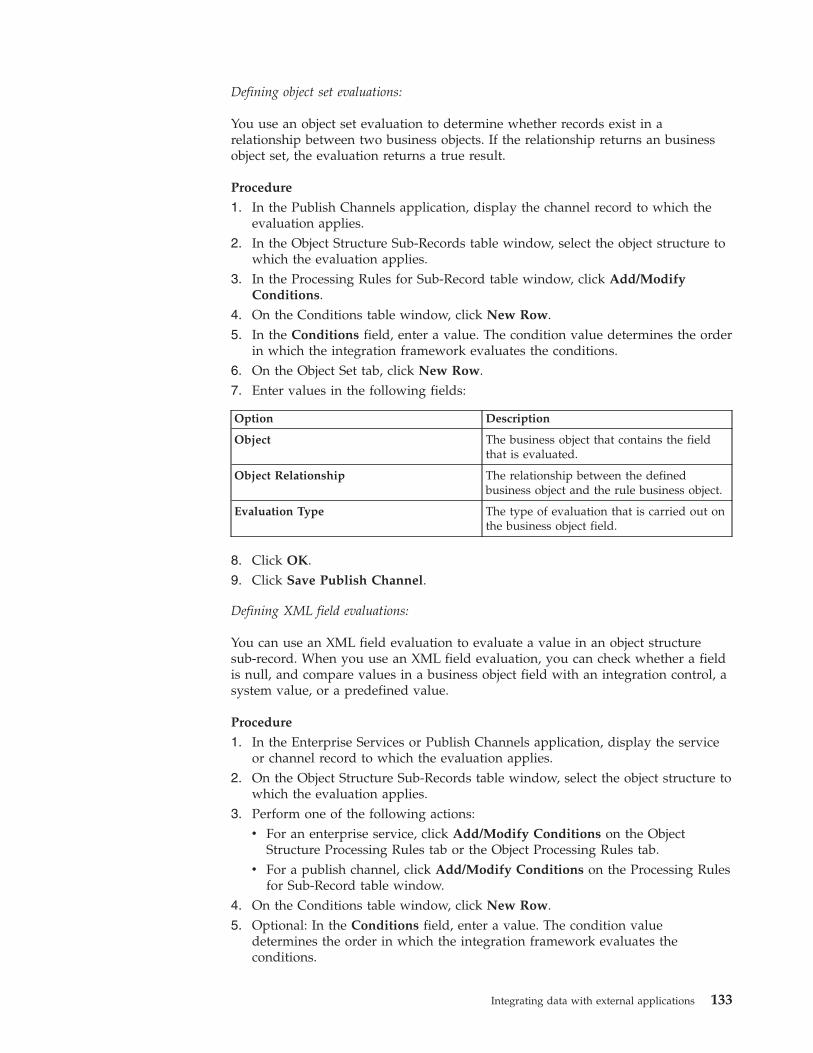
Defining object set evaluations:
You use an object set evaluation to determine whether records exist in arelationship between two business objects. If the relationship returns an businessobject set, the evaluation returns a true result.
Procedure
1. In the Publish Channels application, display the channel record to which theevaluation applies.
2. In the Object Structure Sub-Records table window, select the object structure towhich the evaluation applies.
3. In the Processing Rules for Sub-Record table window, click Add/ModifyConditions.
4. On the Conditions table window, click New Row.5. In the Conditions field, enter a value. The condition value determines the order
in which the integration framework evaluates the conditions.6. On the Object Set tab, click New Row.7. Enter values in the following fields:
Option Description
Object The business object that contains the fieldthat is evaluated.
Object Relationship The relationship between the definedbusiness object and the rule business object.
Evaluation Type The type of evaluation that is carried out onthe business object field.
8. Click OK.9. Click Save Publish Channel.
Defining XML field evaluations:
You can use an XML field evaluation to evaluate a value in an object structuresub-record. When you use an XML field evaluation, you can check whether a fieldis null, and compare values in a business object field with an integration control, asystem value, or a predefined value.
Procedure
1. In the Enterprise Services or Publish Channels application, display the serviceor channel record to which the evaluation applies.
2. On the Object Structure Sub-Records table window, select the object structure towhich the evaluation applies.
3. Perform one of the following actions:v For an enterprise service, click Add/Modify Conditions on the Object
Structure Processing Rules tab or the Object Processing Rules tab.v For a publish channel, click Add/Modify Conditions on the Processing Rules
for Sub-Record table window.4. On the Conditions table window, click New Row.5. Optional: In the Conditions field, enter a value. The condition value
determines the order in which the integration framework evaluates theconditions.
Integrating data with external applications 133
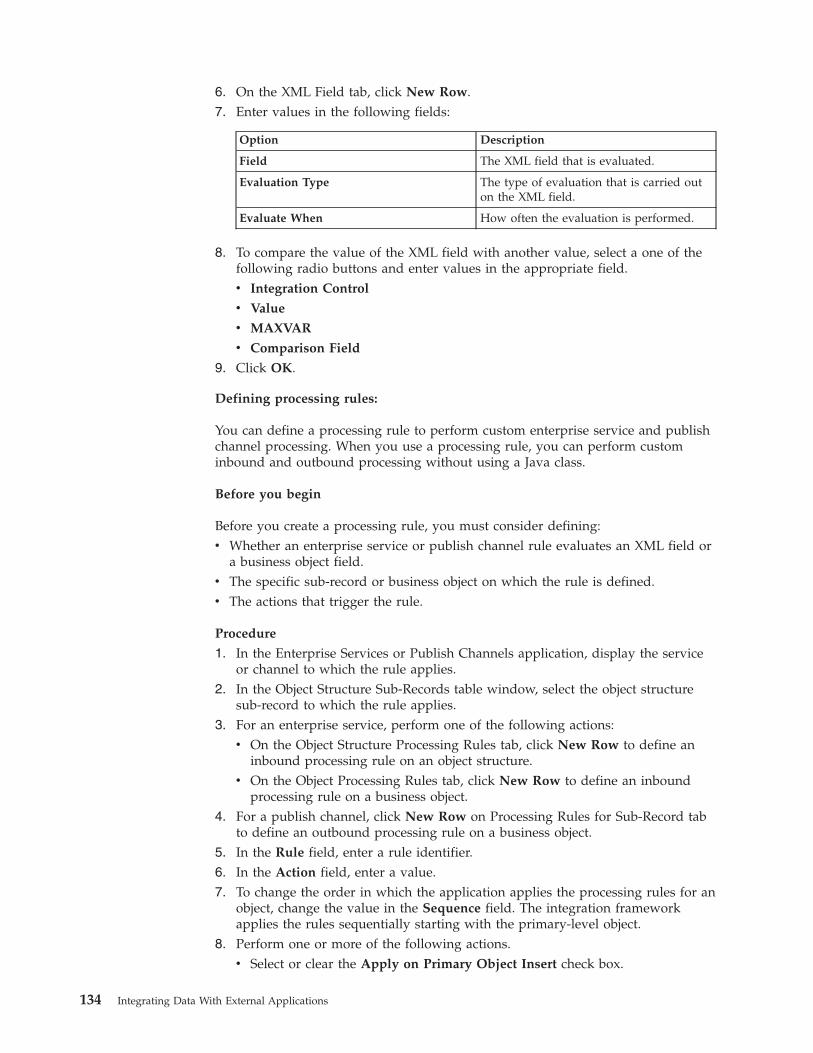
6. On the XML Field tab, click New Row.7. Enter values in the following fields:
Option Description
Field The XML field that is evaluated.
Evaluation Type The type of evaluation that is carried outon the XML field.
Evaluate When How often the evaluation is performed.
8. To compare the value of the XML field with another value, select a one of thefollowing radio buttons and enter values in the appropriate field.v Integration Control
v Value
v MAXVAR
v Comparison Field
9. Click OK.
Defining processing rules:
You can define a processing rule to perform custom enterprise service and publishchannel processing. When you use a processing rule, you can perform custominbound and outbound processing without using a Java class.
Before you begin
Before you create a processing rule, you must consider defining:v Whether an enterprise service or publish channel rule evaluates an XML field or
a business object field.v The specific sub-record or business object on which the rule is defined.v The actions that trigger the rule.
Procedure
1. In the Enterprise Services or Publish Channels application, display the serviceor channel to which the rule applies.
2. In the Object Structure Sub-Records table window, select the object structuresub-record to which the rule applies.
3. For an enterprise service, perform one of the following actions:v On the Object Structure Processing Rules tab, click New Row to define an
inbound processing rule on an object structure.v On the Object Processing Rules tab, click New Row to define an inbound
processing rule on a business object.4. For a publish channel, click New Row on Processing Rules for Sub-Record tab
to define an outbound processing rule on a business object.5. In the Rule field, enter a rule identifier.6. In the Action field, enter a value.7. To change the order in which the application applies the processing rules for an
object, change the value in the Sequence field. The integration frameworkapplies the rules sequentially starting with the primary-level object.
8. Perform one or more of the following actions.v Select or clear the Apply on Primary Object Insert check box.
134 Integrating Data With External Applications
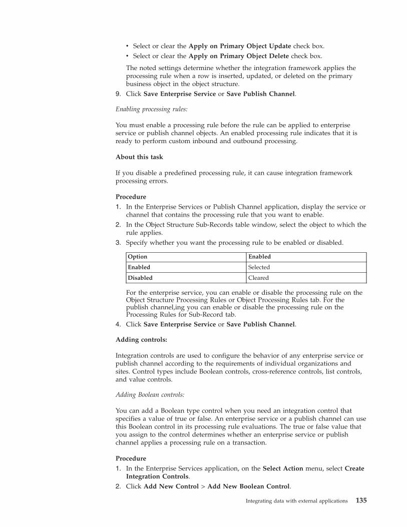
v Select or clear the Apply on Primary Object Update check box.v Select or clear the Apply on Primary Object Delete check box.
The noted settings determine whether the integration framework applies theprocessing rule when a row is inserted, updated, or deleted on the primarybusiness object in the object structure.
9. Click Save Enterprise Service or Save Publish Channel.
Enabling processing rules:
You must enable a processing rule before the rule can be applied to enterpriseservice or publish channel objects. An enabled processing rule indicates that it isready to perform custom inbound and outbound processing.
About this task
If you disable a predefined processing rule, it can cause integration frameworkprocessing errors.
Procedure
1. In the Enterprise Services or Publish Channel application, display the service orchannel that contains the processing rule that you want to enable.
2. In the Object Structure Sub-Records table window, select the object to which therule applies.
3. Specify whether you want the processing rule to be enabled or disabled.
Option Enabled
Enabled Selected
Disabled Cleared
For the enterprise service, you can enable or disable the processing rule on theObject Structure Processing Rules or Object Processing Rules tab. For thepublish channel,ing you can enable or disable the processing rule on theProcessing Rules for Sub-Record tab.
4. Click Save Enterprise Service or Save Publish Channel.
Adding controls:
Integration controls are used to configure the behavior of any enterprise service orpublish channel according to the requirements of individual organizations andsites. Control types include Boolean controls, cross-reference controls, list controls,and value controls.
Adding Boolean controls:
You can add a Boolean type control when you need an integration control thatspecifies a value of true or false. An enterprise service or a publish channel can usethis Boolean control in its processing rule evaluations. The true or false value thatyou assign to the control determines whether an enterprise service or publishchannel applies a processing rule on a transaction.
Procedure
1. In the Enterprise Services application, on the Select Action menu, select CreateIntegration Controls.
2. Click Add New Control > Add New Boolean Control.
Integrating data with external applications 135
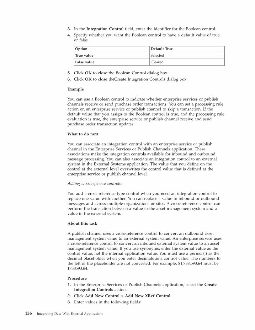
3. In the Integration Control field, enter the identifier for the Boolean control.4. Specify whether you want the Boolean control to have a default value of true
or false.
Option Default True
True value Selected
False value Cleared
5. Click OK to close the Boolean Control dialog box.6. Click OK to close theCreate Integration Controls dialog box.
Example
You can use a Boolean control to indicate whether enterprise services or publishchannels receive or send purchase order transactions. You can set a processing ruleaction on an enterprise service or publish channel to skip a transaction. If thedefault value that you assign to the Boolean control is true, and the processing ruleevaluation is true, the enterprise service or publish channel receive and sendpurchase order transaction updates.
What to do next
You can associate an integration control with an enterprise service or publishchannel in the Enterprise Services or Publish Channels application. Theseassociations make the integration controls available for inbound and outboundmessage processing. You can also associate an integration control to an externalsystem in the External Systems application. The value that you define on thecontrol at the external level overwrites the control value that is defined at theenterprise service or publish channel level.
Adding cross-reference controls:
You add a cross-reference type control when you need an integration control toreplace one value with another. You can replace a value in inbound or outboundmessages and across multiple organizations or sites. A cross-reference control canperform the translation between a value in the asset management system and avalue in the external system.
About this task
A publish channel uses a cross-reference control to convert an outbound assetmanagement system value to an external system value. An enterprise service usesa cross-reference control to convert an inbound external system value to an assetmanagement system value. If you use synonyms, enter the external value as thecontrol value, not the internal application value. You must use a period (.) as thedecimal placeholder when you enter decimals as a control value. The numbers tothe left of the placeholder are not converted. For example, $1,738,593.64 must be1738593.64.
Procedure
1. In the Enterprise Services or Publish Channels application, select the CreateIntegration Controls action.
2. Click Add New Control > Add New XRef Control.3. Enter values in the following fields:
136 Integrating Data With External Applications
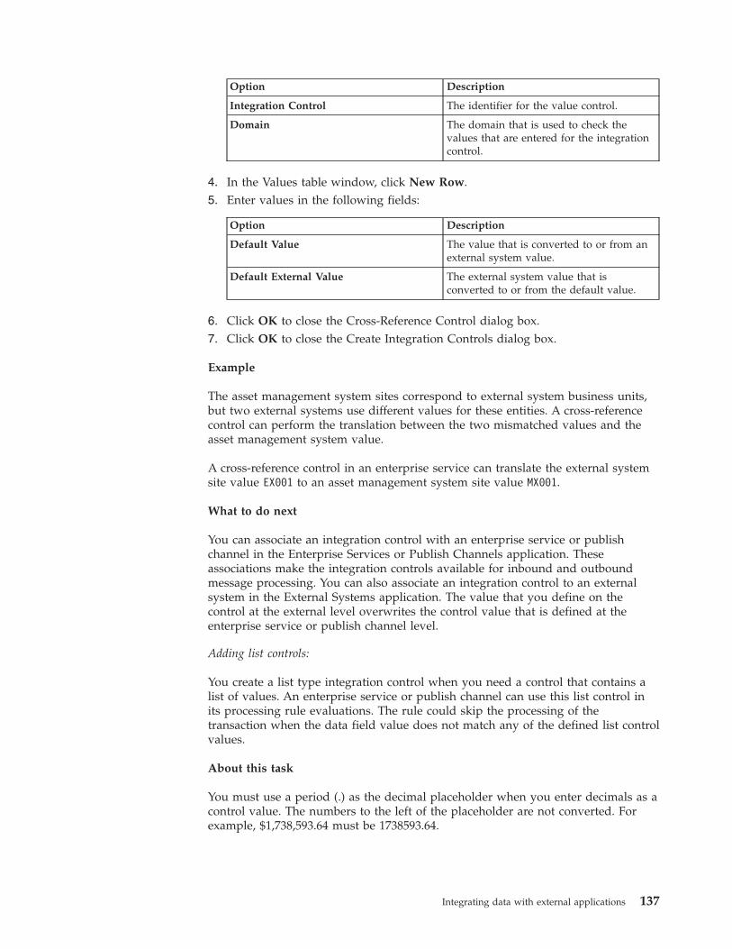
Option Description
Integration Control The identifier for the value control.
Domain The domain that is used to check thevalues that are entered for the integrationcontrol.
4. In the Values table window, click New Row.5. Enter values in the following fields:
Option Description
Default Value The value that is converted to or from anexternal system value.
Default External Value The external system value that isconverted to or from the default value.
6. Click OK to close the Cross-Reference Control dialog box.7. Click OK to close the Create Integration Controls dialog box.
Example
The asset management system sites correspond to external system business units,but two external systems use different values for these entities. A cross-referencecontrol can perform the translation between the two mismatched values and theasset management system value.
A cross-reference control in an enterprise service can translate the external systemsite value EX001 to an asset management system site value MX001.
What to do next
You can associate an integration control with an enterprise service or publishchannel in the Enterprise Services or Publish Channels application. Theseassociations make the integration controls available for inbound and outboundmessage processing. You can also associate an integration control to an externalsystem in the External Systems application. The value that you define on thecontrol at the external level overwrites the control value that is defined at theenterprise service or publish channel level.
Adding list controls:
You create a list type integration control when you need a control that contains alist of values. An enterprise service or publish channel can use this list control inits processing rule evaluations. The rule could skip the processing of thetransaction when the data field value does not match any of the defined list controlvalues.
About this task
You must use a period (.) as the decimal placeholder when you enter decimals as acontrol value. The numbers to the left of the placeholder are not converted. Forexample, $1,738,593.64 must be 1738593.64.
Integrating data with external applications 137
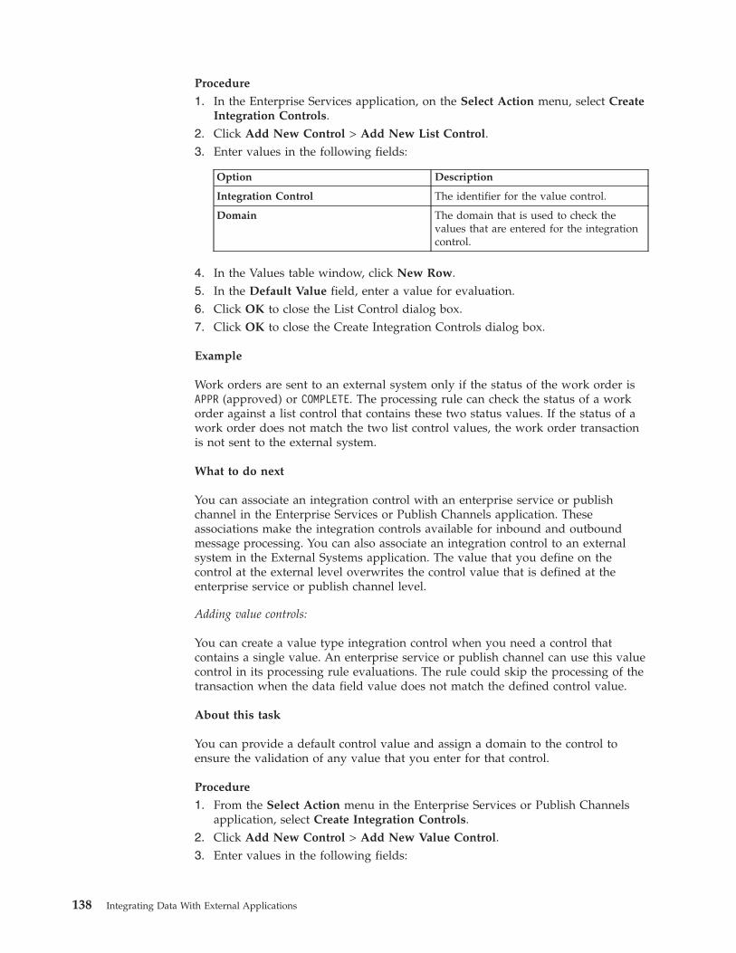
Procedure
1. In the Enterprise Services application, on the Select Action menu, select CreateIntegration Controls.
2. Click Add New Control > Add New List Control.3. Enter values in the following fields:
Option Description
Integration Control The identifier for the value control.
Domain The domain that is used to check thevalues that are entered for the integrationcontrol.
4. In the Values table window, click New Row.5. In the Default Value field, enter a value for evaluation.6. Click OK to close the List Control dialog box.7. Click OK to close the Create Integration Controls dialog box.
Example
Work orders are sent to an external system only if the status of the work order isAPPR (approved) or COMPLETE. The processing rule can check the status of a workorder against a list control that contains these two status values. If the status of awork order does not match the two list control values, the work order transactionis not sent to the external system.
What to do next
You can associate an integration control with an enterprise service or publishchannel in the Enterprise Services or Publish Channels application. Theseassociations make the integration controls available for inbound and outboundmessage processing. You can also associate an integration control to an externalsystem in the External Systems application. The value that you define on thecontrol at the external level overwrites the control value that is defined at theenterprise service or publish channel level.
Adding value controls:
You can create a value type integration control when you need a control thatcontains a single value. An enterprise service or publish channel can use this valuecontrol in its processing rule evaluations. The rule could skip the processing of thetransaction when the data field value does not match the defined control value.
About this task
You can provide a default control value and assign a domain to the control toensure the validation of any value that you enter for that control.
Procedure
1. From the Select Action menu in the Enterprise Services or Publish Channelsapplication, select Create Integration Controls.
2. Click Add New Control > Add New Value Control.3. Enter values in the following fields:
138 Integrating Data With External Applications
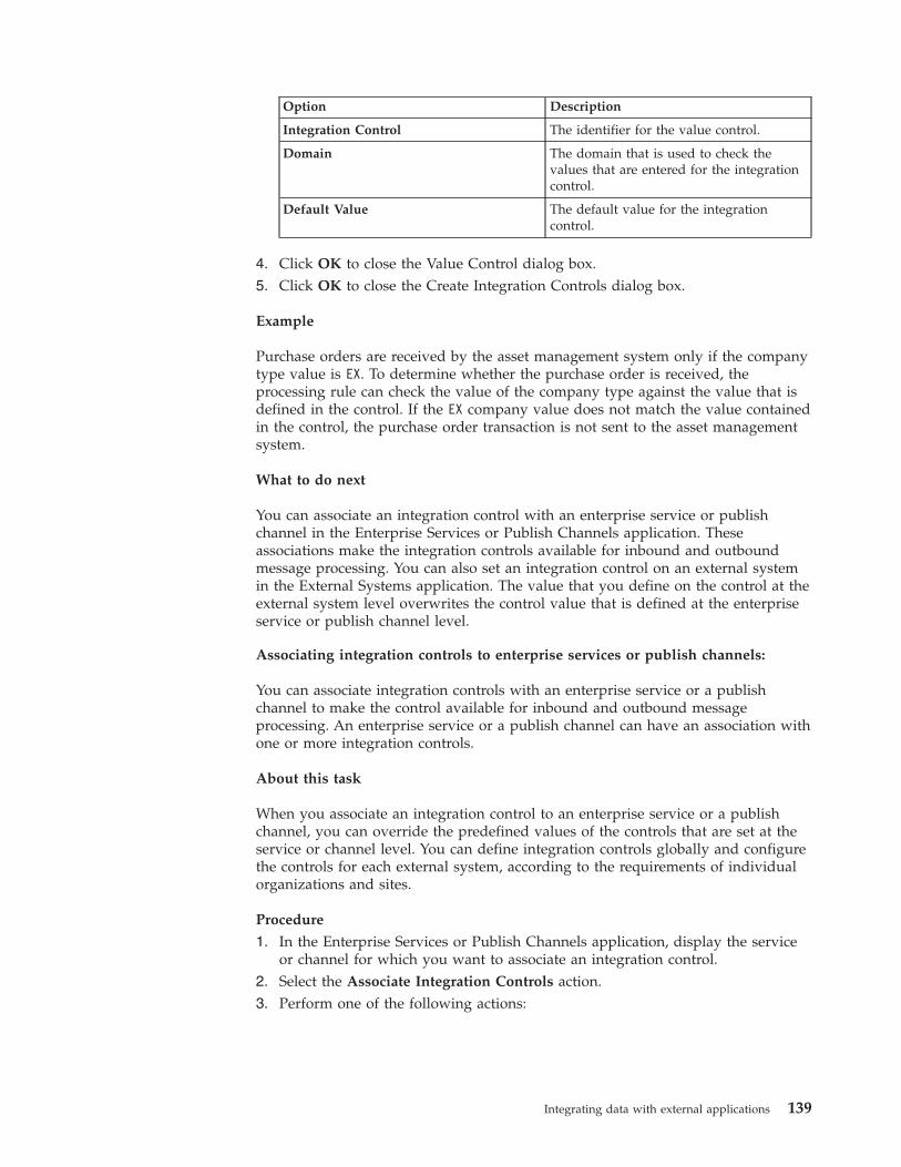
Option Description
Integration Control The identifier for the value control.
Domain The domain that is used to check thevalues that are entered for the integrationcontrol.
Default Value The default value for the integrationcontrol.
4. Click OK to close the Value Control dialog box.5. Click OK to close the Create Integration Controls dialog box.
Example
Purchase orders are received by the asset management system only if the companytype value is EX. To determine whether the purchase order is received, theprocessing rule can check the value of the company type against the value that isdefined in the control. If the EX company value does not match the value containedin the control, the purchase order transaction is not sent to the asset managementsystem.
What to do next
You can associate an integration control with an enterprise service or publishchannel in the Enterprise Services or Publish Channels application. Theseassociations make the integration controls available for inbound and outboundmessage processing. You can also set an integration control on an external systemin the External Systems application. The value that you define on the control at theexternal system level overwrites the control value that is defined at the enterpriseservice or publish channel level.
Associating integration controls to enterprise services or publish channels:
You can associate integration controls with an enterprise service or a publishchannel to make the control available for inbound and outbound messageprocessing. An enterprise service or a publish channel can have an association withone or more integration controls.
About this task
When you associate an integration control to an enterprise service or a publishchannel, you can override the predefined values of the controls that are set at theservice or channel level. You can define integration controls globally and configurethe controls for each external system, according to the requirements of individualorganizations and sites.
Procedure
1. In the Enterprise Services or Publish Channels application, display the serviceor channel for which you want to associate an integration control.
2. Select the Associate Integration Controls action.3. Perform one of the following actions:
Integrating data with external applications 139
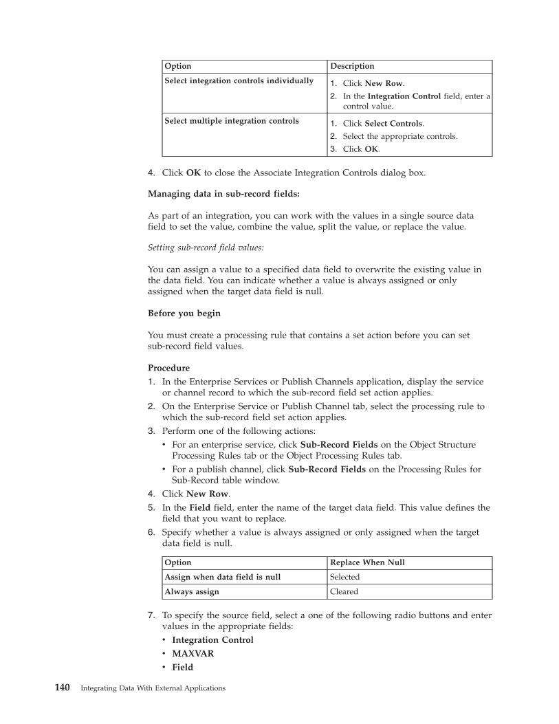
Option Description
Select integration controls individually 1. Click New Row.
2. In the Integration Control field, enter acontrol value.
Select multiple integration controls 1. Click Select Controls.
2. Select the appropriate controls.
3. Click OK.
4. Click OK to close the Associate Integration Controls dialog box.
Managing data in sub-record fields:
As part of an integration, you can work with the values in a single source datafield to set the value, combine the value, split the value, or replace the value.
Setting sub-record field values:
You can assign a value to a specified data field to overwrite the existing value inthe data field. You can indicate whether a value is always assigned or onlyassigned when the target data field is null.
Before you begin
You must create a processing rule that contains a set action before you can setsub-record field values.
Procedure
1. In the Enterprise Services or Publish Channels application, display the serviceor channel record to which the sub-record field set action applies.
2. On the Enterprise Service or Publish Channel tab, select the processing rule towhich the sub-record field set action applies.
3. Perform one of the following actions:v For an enterprise service, click Sub-Record Fields on the Object Structure
Processing Rules tab or the Object Processing Rules tab.v For a publish channel, click Sub-Record Fields on the Processing Rules for
Sub-Record table window.4. Click New Row.5. In the Field field, enter the name of the target data field. This value defines the
field that you want to replace.6. Specify whether a value is always assigned or only assigned when the target
data field is null.
Option Replace When Null
Assign when data field is null Selected
Always assign Cleared
7. To specify the source field, select a one of the following radio buttons and entervalues in the appropriate fields:v Integration Control
v MAXVAR
v Field
140 Integrating Data With External Applications
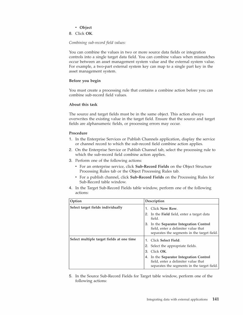
v Object
8. Click OK.
Combining sub-record field values:
You can combine the values in two or more source data fields or integrationcontrols into a single target data field. You can combine values when mismatchesoccur between an asset management system value and the external system value.For example, a two-part external system key can map to a single part key in theasset management system.
Before you begin
You must create a processing rule that contains a combine action before you cancombine sub-record field values.
About this task
The source and target fields must be in the same object. This action alwaysoverwrites the existing value in the target field. Ensure that the source and targetfields are alphanumeric fields, or processing errors may occur.
Procedure
1. In the Enterprise Services or Publish Channels application, display the serviceor channel record to which the sub-record field combine action applies.
2. On the Enterprise Service or Publish Channel tab, select the processing rule towhich the sub-record field combine action applies.
3. Perform one of the following actions:v For an enterprise service, click Sub-Record Fields on the Object Structure
Processing Rules tab or the Object Processing Rules tab.v For a publish channel, click Sub-Record Fields on the Processing Rules for
Sub-Record table window.4. In the Target Sub-Record Fields table window, perform one of the following
actions:
Option Description
Select target fields individually 1. Click New Row.
2. In the Field field, enter a target datafield.
3. In the Separator Integration Controlfield, enter a delimiter value thatseparates the segments in the target field.
Select multiple target fields at one time 1. Click Select Field.
2. Select the appropriate fields.
3. Click OK.
4. In the Separator Integration Controlfield, enter a delimiter value thatseparates the segments in the target field.
5. In the Source Sub-Record Fields for Target table window, perform one of thefollowing actions:
Integrating data with external applications 141
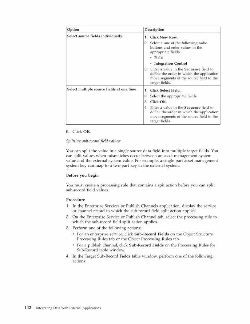
Option Description
Select source fields individually 1. Click New Row.
2. Select a one of the following radiobuttons and enter values in theappropriate fields:
v Field
v Integration Control
3. Enter a value in the Sequence field todefine the order in which the applicationmove segments of the source field to thetarget fields.
Select multiple source fields at one time 1. Click Select Field.
2. Select the appropriate fields.
3. Click OK.
4. Enter a value in the Sequence field todefine the order in which the applicationmove segments of the source field to thetarget fields.
6. Click OK.
Splitting sub-record field values:
You can split the value in a single source data field into multiple target fields. Youcan split values when mismatches occur between an asset management systemvalue and the external system value. For example, a single part asset managementsystem key can map to a two-part key in the external system.
Before you begin
You must create a processing rule that contains a spit action before you can splitsub-record field values.
Procedure
1. In the Enterprise Services or Publish Channels application, display the serviceor channel record to which the sub-record field split action applies.
2. On the Enterprise Service or Publish Channel tab, select the processing rule towhich the sub-record field split action applies.
3. Perform one of the following actions:v For an enterprise service, click Sub-Record Fields on the Object Structure
Processing Rules tab or the Object Processing Rules tab.v For a publish channel, click Sub-Record Fields on the Processing Rules for
Sub-Record table window.4. In the Target Sub-Record Fields table window, perform one of the following
actions:
142 Integrating Data With External Applications
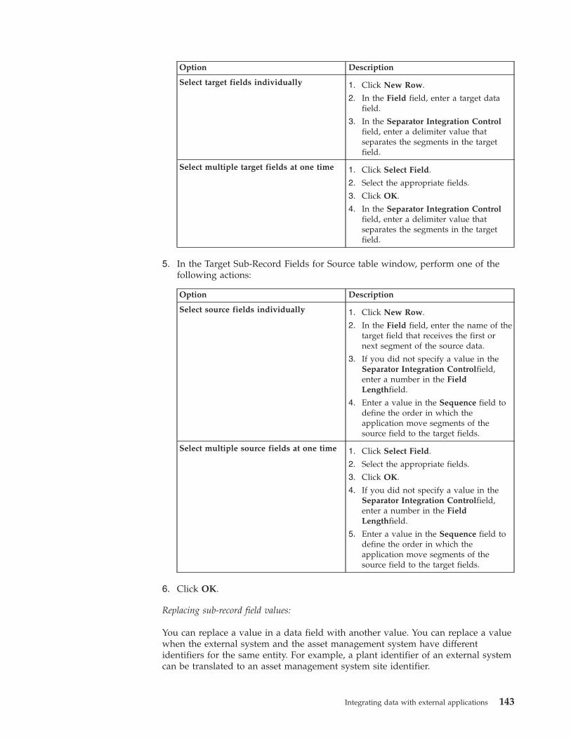
Option Description
Select target fields individually 1. Click New Row.
2. In the Field field, enter a target datafield.
3. In the Separator Integration Controlfield, enter a delimiter value thatseparates the segments in the targetfield.
Select multiple target fields at one time 1. Click Select Field.
2. Select the appropriate fields.
3. Click OK.
4. In the Separator Integration Controlfield, enter a delimiter value thatseparates the segments in the targetfield.
5. In the Target Sub-Record Fields for Source table window, perform one of thefollowing actions:
Option Description
Select source fields individually 1. Click New Row.
2. In the Field field, enter the name of thetarget field that receives the first ornext segment of the source data.
3. If you did not specify a value in theSeparator Integration Controlfield,enter a number in the FieldLengthfield.
4. Enter a value in the Sequence field todefine the order in which theapplication move segments of thesource field to the target fields.
Select multiple source fields at one time 1. Click Select Field.
2. Select the appropriate fields.
3. Click OK.
4. If you did not specify a value in theSeparator Integration Controlfield,enter a number in the FieldLengthfield.
5. Enter a value in the Sequence field todefine the order in which theapplication move segments of thesource field to the target fields.
6. Click OK.
Replacing sub-record field values:
You can replace a value in a data field with another value. You can replace a valuewhen the external system and the asset management system have differentidentifiers for the same entity. For example, a plant identifier of an external systemcan be translated to an asset management system site identifier.
Integrating data with external applications 143
Before you begin
You must create a processing rule that contains a replace action before you canreplace sub-record field values. You must also create a cross-reference control thatcontains the original and new values for the data field.
Procedure
1. In the Enterprise Services or Publish Channels application, display the serviceor channel record to which the sub-record field replace action applies.
2. On the Enterprise Service or Publish Channel tab, select the processing rule towhich the sub-record field replace action applies.
3. Perform one of the following actions:v For an enterprise service, click Sub-Record Fields on the Object Structure
Processing Rules tab or the Object Processing Rules tab.v For a publish channel, click Sub-Record Fields on the Processing Rules for
Sub-Record table window.4. Click New Row.5. In the Field field, enter the name of the target data field. This value defines the
field that you want to replace. The target field must be in the sub-record objectshown at the top of the dialog box.
6. In the Integration Control field, enter the name of the cross-reference typecontrol that contains the original and new values for the target field.
7. Click OK.
Code-based customizationThe integration framework provides placeholders in transaction flows where youcan insert your own code to provide logic that customizes transaction processing.You can insert Java classes or automation scripts at selected points in theprocessing of object structures, publish channels, enterprise services, andinvocation channels. You can also use XSL maps to transform messages.
When you create or update a Java class file, you must rebuild and redeploy theapplication EAR file before integration components can use it. You can write ascript in one of the supported scripting languages in the Automation Scriptsapplication, or you can import a script that you created externally, and you canactivate it for immediate use. When you create or update an XSL map, you caneither store it in the application EAR file or in a directory on your file system.
When the customization code is configured for use, the integration framework callsthe code at the appropriate point during transaction processing.
You can download sample Java classes or XSL files from the IBM Tivoli OpenProcess Automation Library (OPAL).
Customization Java classes and methodsYou can extend the standard processing of outbound and inbound messages byusing Java classes. Multiple placeholders exist in message processing flows whereyou can insert custom Java code to affect message content or processing or both.
External exit classes:
External exit classes provide a base class, ExternalExit, that you can extend tocustomize publish channel, enterprise service, and invocation channel processing.
144 Integrating Data With External Applications
For outbound messages, the input to the external exit class is the irData element ofthe XML message. The output of the class processing is the erData element of theXML message that is delivered to the target destination. For inbound messages, theinput to the external exit class is the erData element of the inbound message. Theoutput is the irData element that is delivered to the related object structure forprocessing into Maximo Asset Management.
To use an external exit class for customization, specify your Java class in theProcessing Class field in the Publish Channels application or in the InvocationChannels application.
An alternative approach to integration customization is to implement a user exitclass. If an adapter for Oracle or SAP is installed, predefined processing classes areprovided, and customizations must be done by using the user exit class. When nopredefined processing classes exist, you can choose whether to implement customcode in the external exit class or the user exit class.
User exit classes:
For inbound and outbound transactions on a publish channel, an enterpriseservice, or an invocation channel, a user exit class can have a preprocessor methodand a postprocessor method. For inbound transactions, the user exit class can havean extra method that processes business objects just before they are committed tothe database.
Preprocessing method for outbound transactions:
The input to the first outbound user exit point is the XML that is generated by theobject structure. If you have an ERP adapter processing class, you can use eitherthe preprocessing method or postprocessing method to implement your customlogic, depending upon your requirement.
By using the preprocessing exit point, you can change data in the message whichlater alters the processing logic of a processing class when it is implemented.
Outbound message customization can be done in the preprocessor method, byusing the following method:public StructureData setUserValueOut(StructureData irData)
This method can perform the following processing:v Validate data.v Change system data by changing the IR record that is sent to the external
system.v Stop the message from being sent out of Maximo Asset Management by
throwing a system exception. The entire message is rolled back. If the message isinitiated by an event, the entire message is also rolled back, including anychanges that you make in an application.
v Stop the message from being sent to the external system by throwing aSKIP_TRANSACTION exception.
v Log the transaction.
Integrating data with external applications 145
Postprocessing method for outbound transactions:
In the postprocessing method of the user exit, the IR element from the objectstructure and the ER element from the XML output of the processing class are bothavailable for processing.
Use the following method to customize outbound messages.public StructureData setUserValueOut(StructureData irData, StructureData erData)
The method can perform the following processes:v Validate data.v Change data by changing the ER record that is sent to the external system.v Map additional data from the irData element to the erData element.v Stop the transaction from being sent out of Maximo Asset Management by
throwing a system exception. The entire message is rolled back. If the message isinitiated by an event,the entire message is also rolled back, including anychanges that you make in an application.
v Stop the message from being sent to the external system by throwing aSKIP_TRANSACTION exception.
v Log the transaction.
You identify the publish channel user exit class in the Publish Channelsapplication.
Preprocessing method for inbound transactions:
In the preprocessing method for inbound transactions, the input is the XMLmessage that is delivered from the external system. If necessary, you can changedata in the message to affect the processing logic in the processing class.
Inbound transaction customization can be done in the first exit by using thefollowing method:public StructureData setUserValueIn(StructureData erData)
This method can perform the following processing:v Validate data.v Change external data by changing the ER record before it is mapped to the IR
record and saved in the system.v Stop further processing of the transaction by throwing an exception. For
queue-based messages, the transaction remains in the queue to be reprocessed.For messages that are not queue-based, the messages are returned to the clientthat started the enterprise service.
v Stop the message from being processed into Maximo Asset Management bythrowing a SKIP_TRANSACTION exception. In this case, the message is notsaved in the system. For queue-based messages, the message is removed fromthe queue.
v Log the transaction.
Postprocessing method for inbound transactions:
In the postprocessing method for inbound transactions, both the IR records and ERrecords are available for processing.
146 Integrating Data With External Applications
Inbound transaction customization can be done in the postprocessing flow byusing the following method:public StructureData setUserValueIn(StructureData irData, StructureData erData)
The method can perform the following processes:v Validate data.v Change external data by changing IR record to be saved in the system.v Map additional data from the ER record to the IR record.v Stop further processing of the transaction by throwing an exception. For
queue-based messages, the transaction remains in the queue for reprocessing.For messages that are not queue-based, the messages are returned to the clientthat started the enterprise service.
v Stop the message from being processed into Maximo Asset Management bythrowing a skip_transaction exception. In this case, the message is not saved inthe system. For queue-based messages, the message is removed from the queue.
v Log the transaction.
You identify the enterprise service user exit class in the Enterprise Servicesapplication.
Business object processing on inbound transactions:
The user exit class on an enterprise service has an additional method,setUserMboIn, that enables custom processing at the point when the businessobjects are created from object structure XML, but are not yet saved to thedatabase.
This user exit is called after the system processing and can run on the objects thatare created in the system by using the following method:public void setUserMboIn(MboRemote mbo)
The object parameter is a reference to a primary object in the object structure.
This method is called once for the primary object. For an XML transaction withmultiple nouns, the object exit is called once for each noun.
The method can perform the following processes:v Validate data.v Stop the transaction from being saved in the system by throwing a system
exception. For queue-based messages, the transaction remains in the queue andis retried.
v Log the transaction.
You identify the user exit class in the Enterprise Services application.
Event filter classes:
For outbound asynchronous transactions that use publish channels, you can run acustom Java class or an automation script by using an event filter class. Theprocessing for an event filter class occurs before the serialization of data in theobject structure layer for an outbound message. The event filter class can insertlogic that affects the creation of the integration message at this processing point.
Integrating data with external applications 147
A common use of the event filter class is to include logic that removes unwantedfields or objects from a message to reduce the amount of data in the serializationprocess. Another common use of the class is to override default recursion logic thatprevents an event from an inbound integration from sending an outboundintegration message. Overriding the default behavior in this scenario can allow anoutbound message to be initiated from an event that is triggered by an inboundmessage.
Handler exit classes:
Multiple predefined methods, or handlers, are provided so that you can send datato an external system, including HTTP, an enterprise Java bean call, and interfacetables. Some of these methods have user exit placeholders that are available forcustomization.
Enterprise bean processing user exit class:
You can use an exit placeholder for class customization when transactions are sentto an external system by an enterprise bean. This exit class is optional and is calledbefore the enterprise bean is called.
The implementation of this Java class must resolve the method signature of theenterprise bean that is started by this handler and the parameters that the methodrequires. If no value is specified for this property, the system applies a default exitcalled DefaultEJBExit. This default exit attempts to resolve the enterprise beanmethod signature and parameters.
This class must implement the psdi.iface.router.EJBExit interface and thefollowing methods:v The getClassParams() method returns the method signature in the form of an
array of Java classes:public Class[] getClassParams()
v The getObjectParams method returns an array of the parameters of theenterprise beans as an array of Java objects:public Object[] getObjectParams(byte[] data, String interfaceName, StringdestinationName)
v After the successful invocation of the enterprise bean, the responseOk() methodis called with an object as the response of the invocation:public void responseOk(Object response)throws MXException
v If an error is encountered during the enterprise bean invocation, theresponseError() method is called with the originating exception as a parameter:public void responseError(Exception e) throws MXException
You enter the fully qualified name of the Java class in the EJBEXIT property of theendpoint that implements the enterprise bean handler.
HTTP processing user exit class:
When you send outbound transactions to an external system by using HTTP, youcan use an HTTP exit placeholder for customization. This exit class is optional andis called as part of the response from the HTTP call.
The HTTP processing exit class runs when a response is returned to an HTTP Postfrom an external system. In the default implementation of the
148 Integrating Data With External Applications
psdi.iface.router.DefaultHTTPExit class, the response code that is received fromthe external system is compared to a range of response codes. The range that isused by the default implementation is 200 - 299. If the code is outside that range,then the transaction was not delivered to the external system, and an exception israised.
With some external systems, the response from an HTTP call is interpreted to seewhether the external system accepted the message. The interpretation logic can beimplemented in the HTTP exit class.
If the publish channel message is not accepted, the code must raise an exception.The message in the outbound queue is marked as an error and is not removedfrom the queue. If the message is accepted, the message is removed from theoutbound queue. If the invocation channel message fails, the exception is returnedto the invoker of the channel, and the invoker handles the exception according tothe design requirements.
The HTTP processing exit class must implement the psdi.iface.router.HTTPExitinterface and implement the following method:
public void processResponseData(int responseCode, String responseMsg,byte[] msgBodyData)
If necessary, this class can interpret the response code and throw an exception. Theclass can perform the following actions:v Check the response code from the HTTP post.v If the response code is in the error range, the exception is logged on the ERROR
level, and a system exception is thrown.v If the response code is valid, the transaction is logged on the DEBUG level.
You must specify the fully qualified name of the Java class in the HTTPEXITproperty of the endpoint that implements the HTTP handler.
JMS processing user exit class:
When you send transactions from the system to an external system by using JMS,you can use an exit placeholder for customization. This exit class is optional and iscalled before the JMS is called.
This class must implement the psdi.iface.router.JMSExit class and the followingmethod:
public Map getMessageProperties(Map metaData, (byte[] data, MaporigProps)throws MXException
This method can perform the following processes:v Change the properties of the JMS messagev Split the data to multiple properties, to match the JMS message
You enter the fully qualified name of the Java class in the JMSEXIT property of theendpoint that implements the JMS handler.
Integrating data with external applications 149
Web service processing user exit class:
You can use an exit placeholder for customization when you send transactionsfrom the system to an external system by using a web service. This exit class isoptional and is called before the web service is started.
This class must implement the psdi.iface.router.WSExit interface and thefollowing methods:
getServiceName() methodThe getServiceName() method returns the service name of the web serviceto start:
public String getServiceName(Map metaData, String endpointURL,String serviceName, String interfaceName, String targetNameSpace)throws MXException
getEndpointURL() methodThe getEndpointURL() method returns the endpoint URL of the webservice to start:
public String getEndpointURL(Map metaData, String endpointURL,String serviceName, String interfaceName, String targetNameSpace)throws MXException
responseOk() methodThe responseOk() method is called after a successful invocation of theexternal web service.
public void responseOk(org.w3c.dom.Document response) throwsMXException
responseError() methodIf an error is encountered during the web service invocation, theresponseError() method is called with the originating exception as aparameter:
public void responseError(Exception e) throws MXException
getOneWayWsInfo() methodThe getOneWayWsInfo() method returns a Boolean value that specifieswhether the web service to start is one way:
public boolean getOneWayWsInfo(Map metaData, String endpointURL,String serviceName, String interfaceName, String targetNameSpace,boolean oneWayWs) throws MXException
getSoapAction() methodThe getSoapAction() method returns the SOAPAction HTTP header to useto start the web service:
public String getSoapAction(Map metaData, String endpointURL, StringserviceName, String interfaceName, String targetNameSpace, StringsoapAction) throws MXException
You must specify the fully qualified name of the Java class in the WSEXIT propertyof the endpoint that implements the web service handler.
The psdi.iface.router.DefaultWSExit class is a default implementation of theWSExit interface. This class overrides the getEndpointURL() method to concatenatethe service name at the end of endpoint URL to form the new endpoint URL.
150 Integrating Data With External Applications
Customization with automation scriptsYou can use automation scripts in place of Java classes to extend the main Javaprocessing classes for predefined integration components. You can use automationscripts to apply custom logic at various points during the processing of objectstructures, publish channels, enterprise services, and invocation channels.
You define automation scripts for integration by using the Automation Scriptsapplication. Defining a script for integration identifies which integrationcomponent the script is associated with and at what point in the processing flowthat the script runs. To test scripts, you can set the log level to debug, activate thescript, and use the data import or data export feature to initiate an integrationtransaction.
Creating automation scripts for integration:
An automation script can customize the processing of integration messages forinbound and outbound transactions. You associate an automation script with anintegration component, and you configure when to insert it into integrationprocessing.
Procedure
1. In the Automation Scripts application, select the Create > Script for Integrationaction.
2. Specify an integration component to associate with the automation script andthen specify the insertion point for the script.
3. Optional: Select the Activate check box if you want the script to beimmediately active.
4. Optional: Specify the logging level to apply when the script executes. Fortesting purposes, if you set the logging level to debug, the logs contain usefulinformation that helps you troubleshoot any issues.
5. Specify the scripting language of the script.6. Either enter the script directly into the Source Code field or browse to the
location where the script is stored and click Import.7. Click Create.
Customization of object structure processing with automation scripts:
Object structure processing supports the simultaneous use of automation scriptsand Java classes for customization. Automation scripts that are defined for anobject structure can affect the processing of data that is directly processed throughthe object structure, such as the REST API, or through other integrationcomponents such as publish channels and enterprise services.
Insertion points for customization of object structure processing with automation scripts:
You can insert script-based processing into the Java definition classes and Javaprocessing classes that transform object structures during integration processing.
The illustration shows the insertion of automation scripts during the inbound andoutbound processing of object structures.
Integrating data with external applications 151
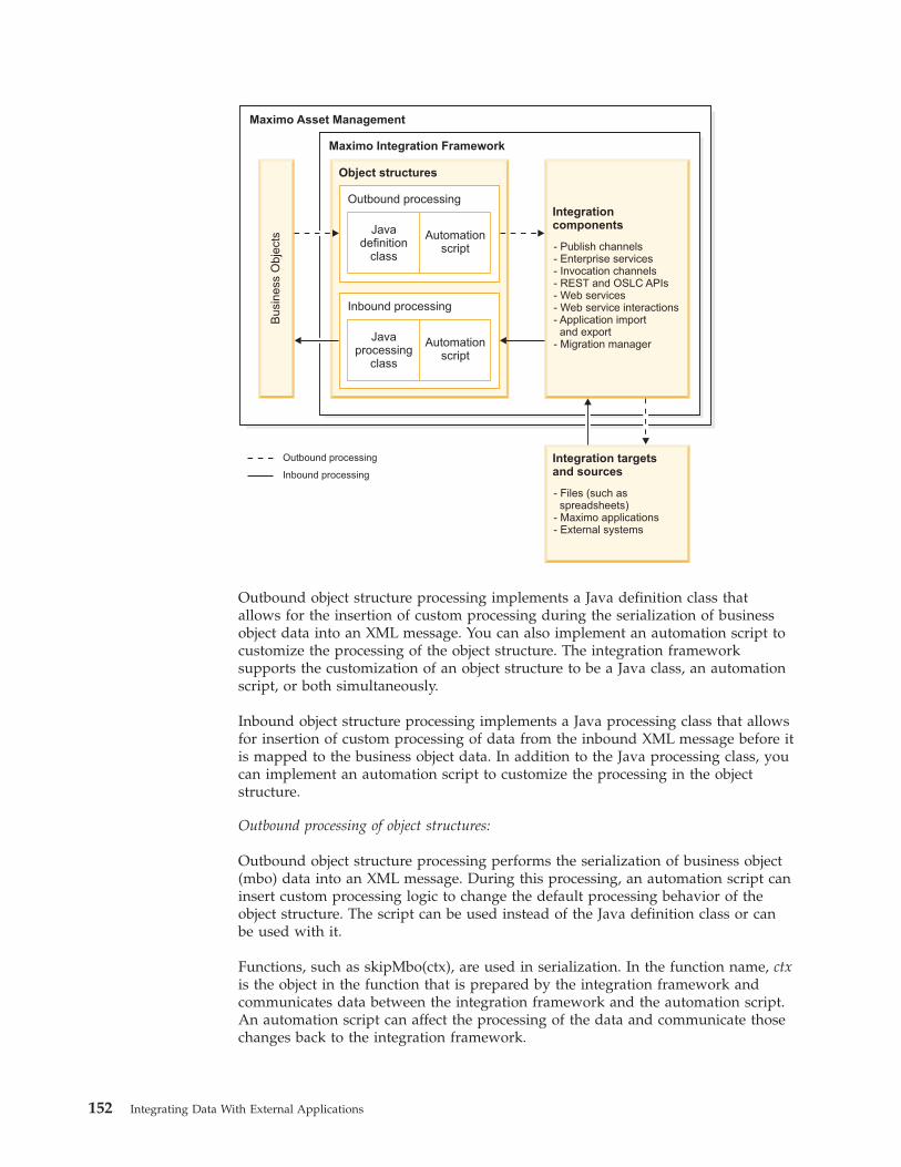
Integrationcomponents
- Publish channels- Enterprise services- Invocation channels- REST and OSLC APIs- Web services- Web service interactions- Application importand export
- Migration manager
Integration targetsand sources
- Files (such asspreadsheets)
- Maximo applications- External systems
Maximo Asset Management
Outbound processing
Inbound processing
Maximo Integration Framework
Busin
ess
Obje
cts
Object structures
Outbound processing
Javadefinition
class
Automationscript
Inbound processing
Javaprocessing
class
Automationscript
Outbound object structure processing implements a Java definition class thatallows for the insertion of custom processing during the serialization of businessobject data into an XML message. You can also implement an automation script tocustomize the processing of the object structure. The integration frameworksupports the customization of an object structure to be a Java class, an automationscript, or both simultaneously.
Inbound object structure processing implements a Java processing class that allowsfor insertion of custom processing of data from the inbound XML message before itis mapped to the business object data. In addition to the Java processing class, youcan implement an automation script to customize the processing in the objectstructure.
Outbound processing of object structures:
Outbound object structure processing performs the serialization of business object(mbo) data into an XML message. During this processing, an automation script caninsert custom processing logic to change the default processing behavior of theobject structure. The script can be used instead of the Java definition class or canbe used with it.
Functions, such as skipMbo(ctx), are used in serialization. In the function name, ctxis the object in the function that is prepared by the integration framework andcommunicates data between the integration framework and the automation script.An automation script can affect the processing of the data and communicate thosechanges back to the integration framework.
152 Integrating Data With External Applications
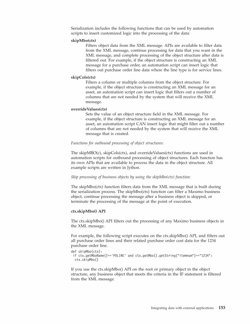
Serialization includes the following functions that can be used by automationscripts to insert customized logic into the processing of the data:
skipMbo(ctx)Filters object data from the XML message. APIs are available to filter datafrom the XML message, continue processing for data that you want in theXML message, and complete processing of the object structure after data isfiltered out. For example, if the object structure is constructing an XMLmessage for a purchase order, an automation script can insert logic thatfilters out purchase order line data where the line type is for service lines.
skipCols(ctx)Filters a column or multiple columns from the object structure. Forexample, if the object structure is constructing an XML message for anasset, an automation script can insert logic that filters out a number ofcolumns that are not needed by the system that will receive the XMLmessage.
overrideValues(ctx)Sets the value of an object structure field in the XML message. Forexample, if the object structure is constructing an XML message for anasset, an automation script CAN insert logic that might filter out a numberof columns that are not needed by the system that will receive the XMLmessage that is created.
Functions for outbound processing of object structures:
The skipMBO(c), skipCols(ctx), and overrideValues(ctx) functions are used inautomation scripts for outbound processing of object structures. Each function hasits own APIs that are available to process the data in the object structure. Allexample scripts are written in Jython.
Skip processing of business objects by using the skipMbo(ctx) function:
The skipMbo(ctx) function filters data from the XML message that is built duringthe serialization process. The skipMbo(ctx) function can filter a Maximo businessobject, continue processing the message after a business object is skipped, orterminate the processing of the message at the point of execution.
ctx.skipMbo() API
The ctx.skipMbo() API filters out the processing of any Maximo business objects inthe XML message.
For example, the following script executes on the ctx.skipMbo() API, and filters outall purchase order lines and their related purchase order cost data for the 1234purchase order line.def skipMbo(ctx):if ctx.getMboName()=='POLINE' and ctx.getMbo().getString("itemnum")=="1234":ctx.skipMbo()
If you use the ctx.skipMbo() API on the root or primary object in the objectstructure, any business object that meets the criteria in the IF statement is filteredfrom the XML message.
Integrating data with external applications 153
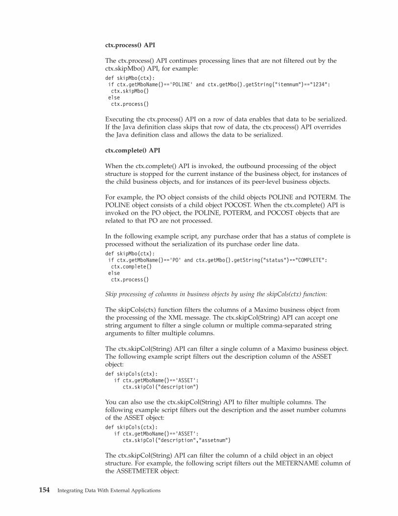
ctx.process() API
The ctx.process() API continues processing lines that are not filtered out by thectx.skipMbo() API, for example:def skipMbo(ctx):if ctx.getMboName()=='POLINE' and ctx.getMbo().getString("itemnum")=="1234":ctx.skipMbo()elsectx.process()
Executing the ctx.process() API on a row of data enables that data to be serialized.If the Java definition class skips that row of data, the ctx.process() API overridesthe Java definition class and allows the data to be serialized.
ctx.complete() API
When the ctx.complete() API is invoked, the outbound processing of the objectstructure is stopped for the current instance of the business object, for instances ofthe child business objects, and for instances of its peer-level business objects.
For example, the PO object consists of the child objects POLINE and POTERM. ThePOLINE object consists of a child object POCOST. When the ctx.complete() API isinvoked on the PO object, the POLINE, POTERM, and POCOST objects that arerelated to that PO are not processed.
In the following example script, any purchase order that has a status of complete isprocessed without the serialization of its purchase order line data.def skipMbo(ctx):if ctx.getMboName()=='PO' and ctx.getMbo().getString("status")=="COMPLETE":ctx.complete()elsectx.process()
Skip processing of columns in business objects by using the skipCols(ctx) function:
The skipCols(ctx) function filters the columns of a Maximo business object fromthe processing of the XML message. The ctx.skipCol(String) API can accept onestring argument to filter a single column or multiple comma-separated stringarguments to filter multiple columns.
The ctx.skipCol(String) API can filter a single column of a Maximo business object.The following example script filters out the description column of the ASSETobject:def skipCols(ctx):
if ctx.getMboName()==’ASSET’:ctx.skipCol("description")
You can also use the ctx.skipCol(String) API to filter multiple columns. Thefollowing example script filters out the description and the asset number columnsof the ASSET object:def skipCols(ctx):
if ctx.getMboName()==’ASSET’:ctx.skipCol("description",”assetnum”)
The ctx.skipCol(String) API can filter the column of a child object in an objectstructure. For example, the following script filters out the METERNAME column ofthe ASSETMETER object:
154 Integrating Data With External Applications
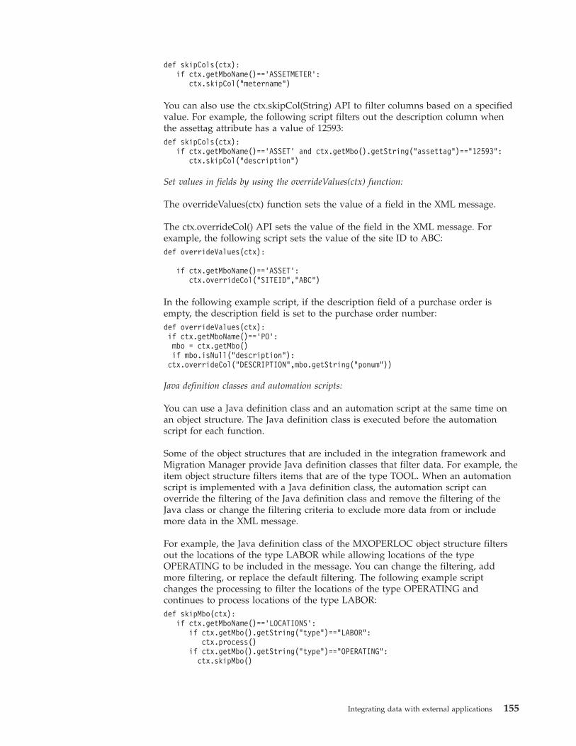
def skipCols(ctx):if ctx.getMboName()==’ASSETMETER’:
ctx.skipCol("metername”)
You can also use the ctx.skipCol(String) API to filter columns based on a specifiedvalue. For example, the following script filters out the description column whenthe assettag attribute has a value of 12593:def skipCols(ctx):
if ctx.getMboName()==’ASSET’ and ctx.getMbo().getString("assettag")=="12593":ctx.skipCol("description")
Set values in fields by using the overrideValues(ctx) function:
The overrideValues(ctx) function sets the value of a field in the XML message.
The ctx.overrideCol() API sets the value of the field in the XML message. Forexample, the following script sets the value of the site ID to ABC:def overrideValues(ctx):
if ctx.getMboName()==’ASSET’:ctx.overrideCol("SITEID","ABC")
In the following example script, if the description field of a purchase order isempty, the description field is set to the purchase order number:def overrideValues(ctx):if ctx.getMboName()=='PO':mbo = ctx.getMbo()if mbo.isNull("description"):ctx.overrideCol("DESCRIPTION",mbo.getString("ponum"))
Java definition classes and automation scripts:
You can use a Java definition class and an automation script at the same time onan object structure. The Java definition class is executed before the automationscript for each function.
Some of the object structures that are included in the integration framework andMigration Manager provide Java definition classes that filter data. For example, theitem object structure filters items that are of the type TOOL. When an automationscript is implemented with a Java definition class, the automation script canoverride the filtering of the Java definition class and remove the filtering of theJava class or change the filtering criteria to exclude more data from or includemore data in the XML message.
For example, the Java definition class of the MXOPERLOC object structure filtersout the locations of the type LABOR while allowing locations of the typeOPERATING to be included in the message. You can change the filtering, addmore filtering, or replace the default filtering. The following example scriptchanges the processing to filter the locations of the type OPERATING andcontinues to process locations of the type LABOR:def skipMbo(ctx):
if ctx.getMboName()==’LOCATIONS’:if ctx.getMbo().getString("type")=="LABOR":
ctx.process()if ctx.getMbo().getString("type")=="OPERATING":
ctx.skipMbo()
Integrating data with external applications 155
The following example script adds more filtering for the MXOPERLOC objectstructure by filtering out type COURIER:
if ctx.getMboName()==’LOCATIONS’:if ctx.getMbo().getString("type")=="COURIER":
ctx.skipMbo()
The following example script replaces the definition class filtering so that onlylocations of type COURIER are filtered out:def skipMbo(ctx):
if ctx.getMboName()==’LOCATIONS’:if ctx.getMbo().getString("type")=="COURIER":
ctx.skipMbo()else:
ctx.process()
Inbound processing of object structures:
The processing of inbound messages by the integration framework supports theuse of automation scripts on the object structure to support custom logic. This useof automation scripts allows customization for any inbound integration messagethat uses an object structure and for customization of processing MigrationManager data.
For integration processing, a script that is implemented on the object structureapplies to messages from the following sources:v Data importv RESTv Application importv Web servicev OSLCv Integration servletv Integration tables
The object structure supports a Java processing class or an automation script. Youcan use a Java processing class, an automation script, or both on the same objectstructure. The processing supports functions that are in either the class file or theautomation script.
A context (ctx) is passed between the processing class of the inbound objectstructure and the automation script, which implements the custom code. Thecontext is supported bidirectionally. Predefined APIs are available for the context.The script framework provides a built-in Java class that prepares a context.
All of the following code examples and fragments use JavaScript. You canimplement the logic at the following points in the processing:v Before the processing of a Maximo business object. For example, the
beforeProcess(ctx) function is processed once for each noun in the inboundmessage before business objects that are related to the message are created.
v During the processing of a Maximo business object. For example, thebeforeCreateMboSet(ctx) function is processed sequentially for each object withinevery noun in the inbound message. Other functions that are processedsequentially include afterCreateMboSet(ctx), mboRules(ctx), beforeMboData(ctx),and afterMboData(ctx).
156 Integrating Data With External Applications
v After Maximo business object processing completes. For example, thepreSaveRules(ctx) and changeStatus(ctx) functions are processed once for eachnoun in the inbound message after the business objects are created.
In the Automation Scripts application, you can create a script for integration toinclude in the object structure processing.
Functions for inbound processing of object structures:
Each function provides APIs that you can use to customize the processing of thedata in the object structure.
Skip or change message processing by using the beforeProcess(ctx) function:
The beforeProcess(ctx) function provides an injection point to run the logic in theautomation script before business objects are created.
For example, you can skip the processing of a message that is based on theevaluation of the data in the XML message. Another example is to change theaction attribute for the message from Sync to Create.
The following JavaScript example sets the message action to Sync:function beforeProcess(ctx){
ctx.setMsgType("Sync");}
Create business object sets by using the beforeCreateMboSet(ctx) function:
The beforeCreateMBOSet(ctx) function processes inbound data before theframework creates the Maximo business objects or business object sets and canoperate on all business objects in the object structure.
If an automation script that is processing an object structure creates a businessobject set, then the createMboSet() function in the base class is skipped. Processingof a child business object supports access to the parent object by using thegetParentMbo() function.
You can also use the beforeCreateMboSet(ctx) function to conditionally create thebusiness object that is based on the data that is included in the XML message.
You cannot create a child business object that is independent of its parent businessobject.
The following example shows how to create a child business object from a parentbusiness object.importPackage(Packages.psdi.server);function beforeCreateMboSet(ctx){var struc=ctx.getData();var ponum=struc.getCurrentData("PO",ctx.getUserInfo();var siteid=struc.getCurrentData("SITEID");var poSet = MXServer.getMXServer().getMboSet("PO",ctx.getUserInfo());poSet.setQbeExactMatch(true);poSet.setQbe("ponum",ponum);poSet.setQbe("siteid",siteid);
Integrating data with external applications 157
var poMbo = poSet.moveFirst();var polineSet = poMbo.getMboSet("POLINE");ctx.setMboSet(polineSet);}
Change business objects or business object sets by using the afterCreateMboSet(ctx)function:
The afterCreateMboSet(ctx) function processes the inbound object structure afterthe framework creates the Maximo business object or business object set.
The afterCreateMboSet(ctx) function is available to operate on all business objectsin the object structure. This function can change the business object or businessobject set that the framework created or can inject more business objects into thebusiness object set.
The following example sets an MboSet property to note that the created locationhas a type of Storeroom. This logic replaces the default logic that is in theMXSTORELOC processing class.importPackage(Packages.psdi.server);function afterCreateMboSet(ctx){
var loc type = MXServer.getMXServer().getMaximoDD().getTranslator().toInternalString("LOCTYPE",ctx.getData().getCurrentData("TYPE"));
if (loc Type=="STOREROOM"){
ctx.getPrimaryMboSet().setStoreroom();}
else{
ctx.getPrimaryMboSet().setNonStoreroom();}
}
Change processing of rules by using the mboRules(ctx) function:
The mboRules(ctx) function can skip the processing of a business object, skip atransaction, continue processing, or create a business object. This function operatesbefore the creation of each Maximo business object.
The following example shows how to skip a transaction:function mboRules(ctx){
ctx.skipTxn();}
Set values in fields by using the beforeMboData(ctx) function:
The beforeMboData(ctx) function is available when the Maximo business object iscreated but before the values in the business object are set by the integrationframework. Processing of the object structure can change the setting of businessobject data. Processing can also set flags on the fields, such as thesamevaluevalidation flag, which triggers field validations even when the fieldvalue is set with the current value of the field.
Add business objects and change values in fields by using the afterMboData(ctx)function:
The afterMboData(ctx) function implements custom logic to create an extra relatedMaximo business object for inclusion in the transaction or change data in a
158 Integrating Data With External Applications
Maximo business object. The function is available after the business object iscreated and the values are set in the Maximo business object by the integrationframework.
When columns in the object structure are restricted, you can use theafterMboData(ctx) function to provide the logic to set those columns instead ofhaving the integration framework set the values.
In the following example, an asset is created with the description field set to aconcatenation of the EXTERNALREFID field and the description field that is passedfrom the object structure:importPackage(Packages.psdi.server);importPackage(Packages.psdi.mbo);function afterMboData(ctx){
var mbo = ctx.getMbo();var struc = ctx.getData();mbo.setValue("description", "FROM: "+struc.getCurrentData("EXTERNALREFID")+ " DESC: "+struc.getCurrentData("DESCRIPTION"));
}
Change the transaction before saving to the database by using the preSaveRules(ctx)function:
The preSaveRules(ctx) function allows for extra processing that is related to thetransaction as a whole. You can use the preSaveRules(ctx) function to create arelated object and add it to the transaction. The function is called before the Saveaction and is called for each noun in the message.
Change status or status date by using the changeStatus(ctx) function:
The changeStatus(ctx) function implements a status change outside thestatefulMicSetIn class that is available in the integration framework. You can alsouse this function to set the status date with a value instead of using the systemdate.
For the automation script to use the changeStatus(ctx) function, thestatefulMicSetin class or the class that extends the statefulMicSetin class must beregistered as the processing class in the object structure. You can use this functionto support a status change for five parameters. The base class supports only threeparameters.
The following example sets the memo field that is related to the change statusaction to a string value if the NP_STATUSMEMO field does not contain a value:importPackage(Packages.psdi.server);importPackage(Packages.psdi.mbo);
function changeStatus(ctx){
var mbo = ctx.getMbo();var struc = ctx.getData();var stat = struc.getCurrentData("STATUS");var memo = struc.getCurrentData("NP_STATUSMEMO");if(struc.isCurrentDataNull("NP_STATUSMEMO")){
memo = "Status change via Integration";}mbo.changeStatus(stat, MXServer.getMXServer().getDate(), memo, MboCon-stants.NOACCESSCHECK);
}
Integrating data with external applications 159
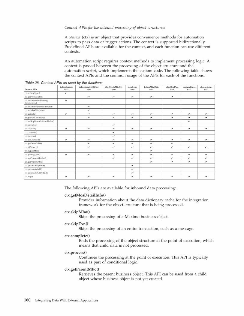
Context APIs for the inbound processing of object structures:
A context (ctx) is an object that provides convenience methods for automationscripts to pass data or trigger actions. The context is supported bidirectionally.Predefined APIs are available for the context, and each function can use differentcontexts.
An automation script requires context methods to implement processing logic. Acontext is passed between the processing of the object structure and theautomation script, which implements the custom code. The following table showsthe context APIs and the common usage of the APIs for each of the functions:
Table 28. Context APIs as used by the functions
Context APIsbeforeProcess
(ctx)beforeCreateMBOSet
(ctx)afterCreateMboSet
(ctx)mboRules
(ctx)beforeMboData
(ctx)afterMboData
(ctx)preSaveRules
(ctx)changeStatus
(ctx)
ctx.setMsgType() U
ctx.getProcessTable() U U U U U
ctx.setProcessTable(StringProcessTable)
U
ctx.setMboSet(MboSet mboSet) U
ctx.setMbo(Mbo mbo) U
ctx.getData() U U U U U U U U
ctx.getMosDetailInfo() U U U U U U U
ctx.setSkipBaseAdditionalRules() U
ctx.skipMbo() U
ctx.skipTxn() U U U U U U U U
ctx.complete() U
ctx.process() U
ctx.getUserInfo() U U U U U U U U
ctx.getParentMbo() U U U U U
ctx.isPrimary() U U U U U U U
ctx.bypassMbo() U
ctx.getMsgType() U U U U U U U U
ctx.getPrimaryMboSet() U U U U U U
ctx.getPrimaryMbo() U U U U
ctx.processAsUpdate() U
ctx.processAsAdd() U
ctx.processAsAddAtEnd() U
ctx.log () U U U U U U U U
The following APIs are available for inbound data processing:
ctx.getMosDetailInfo()Provides information about the data dictionary cache for the integrationframework for the object structure that is being processed.
ctx.skipMbo()Skips the processing of a Maximo business object.
ctx.skipTxn()Skips the processing of an entire transaction, such as a message.
ctx.complete()Ends the processing of the object structure at the point of execution, whichmeans that child data is not processed.
ctx.process()Continues the processing at the point of execution. This API is typicallyused as part of conditional logic.
ctx.getParentMbo()Retrieves the parent business object. This API can be used from a childobject whose business object is not yet created.
160 Integrating Data With External Applications
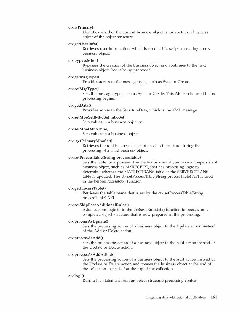
ctx.isPrimary()Identifies whether the current business object is the root-level businessobject of the object structure.
ctx.getUserInfo()Retrieves user information, which is needed if a script is creating a newbusiness object.
ctx.bypassMbo()Bypasses the creation of the business object and continues to the nextbusiness object that is being processed.
ctx.getMsgType()Provides access to the message type, such as Sync or Create.
ctx.setMsgType()Sets the message type, such as Sync or Create. This API can be used beforeprocessing begins.
ctx.getData()Provides access to the StructureData, which is the XML message.
ctx.setMboSet(MboSet mboSet)Sets values in a business object set.
ctx.setMbo(Mbo mbo)Sets values in a business object.
ctx. getPrimaryMboSet()Retrieves the root business object of an object structure during theprocessing of a child business object.
ctx.setProcessTable(String processTable)Sets the table for a process. The method is used if you have a nonpersistentbusiness object, such as MXRECEIPT, that has processing logic todetermine whether the MATRECTRANS table or the SERVRECTRANStable is updated. The ctx.setProcessTable(String processTable) API is usedin the beforeProcess(ctx) function.
ctx.getProcessTable()Retrieves the table name that is set by the ctx.setProcessTable(StringprocessTable) API.
ctx.setSkipBaseAdditionalRules()Adds custom logic to in the preSaveRules(ctx) function to operate on acompleted object structure that is now prepared in the processing.
ctx.processAsUpdate()Sets the processing action of a business object to the Update action insteadof the Add or Delete action.
ctx.processAsAdd()Sets the processing action of a business object to the Add action instead ofthe Update or Delete action.
ctx.processAsAddAtEnd()Sets the processing action of a business object to the Add action instead ofthe Update or Delete action and creates the business object at the end ofthe collection instead of at the top of the collection.
ctx.log ()Runs a log statement from an object structure processing context.
Integrating data with external applications 161
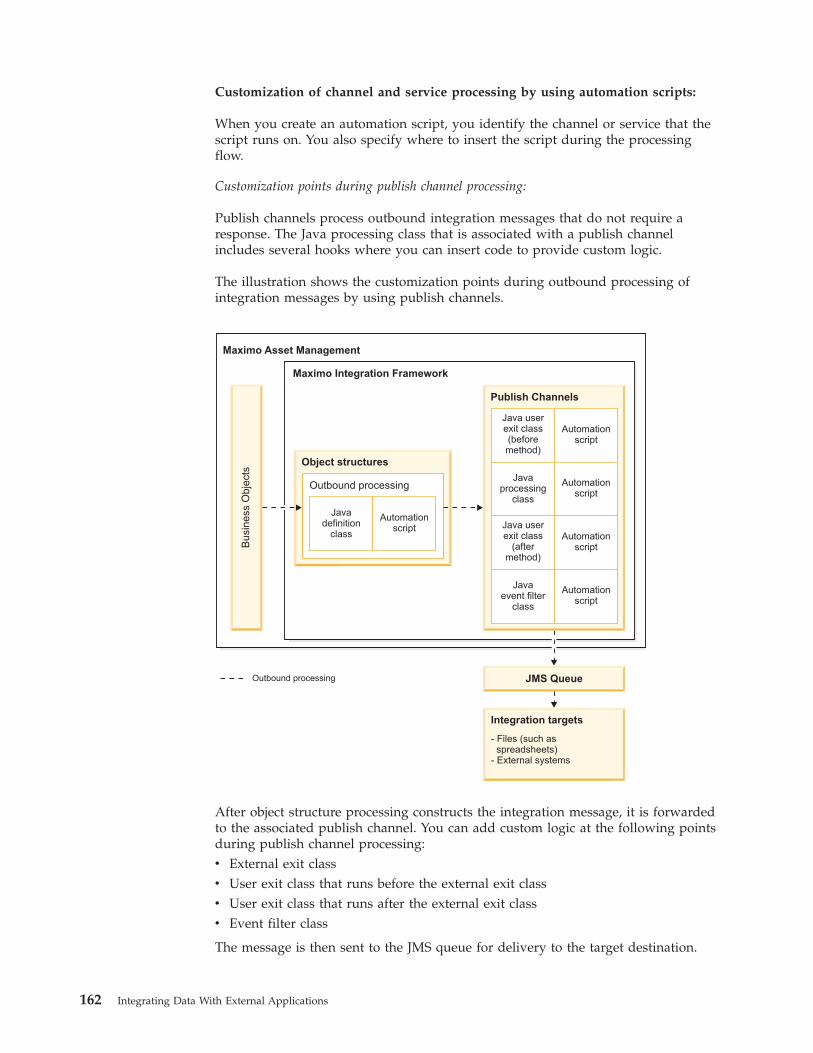
Customization of channel and service processing by using automation scripts:
When you create an automation script, you identify the channel or service that thescript runs on. You also specify where to insert the script during the processingflow.
Customization points during publish channel processing:
Publish channels process outbound integration messages that do not require aresponse. The Java processing class that is associated with a publish channelincludes several hooks where you can insert code to provide custom logic.
The illustration shows the customization points during outbound processing ofintegration messages by using publish channels.
Outbound processing
Maximo Asset Management
Maximo Integration Framework
Bu
sin
ess
Ob
jects
Object structures
Outbound processing
Javadefinition
class
Automationscript
JMS Queue
Integration targets
- Files (such asspreadsheets)
- External systems
Publish Channels
Java userexit class(beforemethod)
Automationscript
Javaprocessing
class
Automationscript
Java userexit class
(aftermethod)
Automationscript
Javaevent filter
class
Automationscript
After object structure processing constructs the integration message, it is forwardedto the associated publish channel. You can add custom logic at the following pointsduring publish channel processing:v External exit classv User exit class that runs before the external exit classv User exit class that runs after the external exit classv Event filter class
The message is then sent to the JMS queue for delivery to the target destination.
162 Integrating Data With External Applications
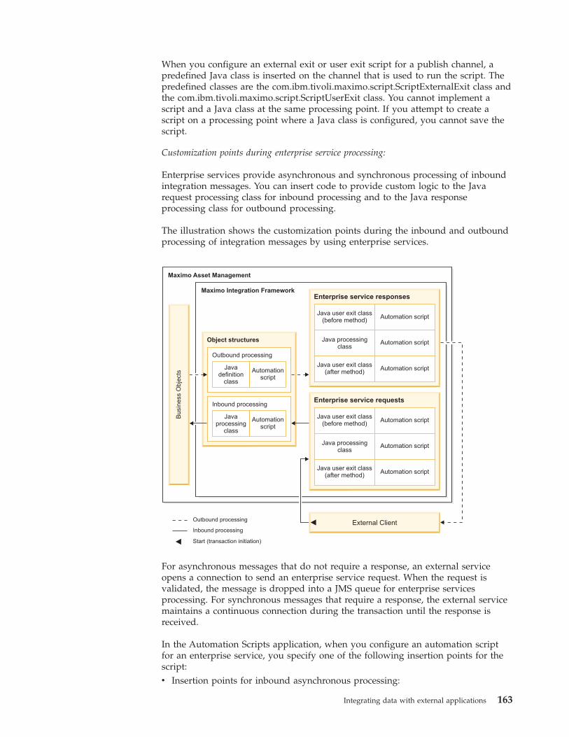
When you configure an external exit or user exit script for a publish channel, apredefined Java class is inserted on the channel that is used to run the script. Thepredefined classes are the com.ibm.tivoli.maximo.script.ScriptExternalExit class andthe com.ibm.tivoli.maximo.script.ScriptUserExit class. You cannot implement ascript and a Java class at the same processing point. If you attempt to create ascript on a processing point where a Java class is configured, you cannot save thescript.
Customization points during enterprise service processing:
Enterprise services provide asynchronous and synchronous processing of inboundintegration messages. You can insert code to provide custom logic to the Javarequest processing class for inbound processing and to the Java responseprocessing class for outbound processing.
The illustration shows the customization points during the inbound and outboundprocessing of integration messages by using enterprise services.
Outbound processing
Inbound processing
Maximo Asset Management
Maximo Integration Framework
Busin
ess
Obje
cts
Object structures
Outbound processing
Javadefinition
class
Automationscript
Inbound processing
Javaprocessing
class
Automationscript
Enterprise service responses
Java user exit class(before method)
Java processingclass
Java user exit class(after method)
Automation script
Automation script
Automation script
Enterprise service requests
Java user exit class(before method)
Java processingclass
Java user exit class(after method)
Automation script
Automation script
Automation script
External Client
Start (transaction initiation)
For asynchronous messages that do not require a response, an external serviceopens a connection to send an enterprise service request. When the request isvalidated, the message is dropped into a JMS queue for enterprise servicesprocessing. For synchronous messages that require a response, the external servicemaintains a continuous connection during the transaction until the response isreceived.
In the Automation Scripts application, when you configure an automation scriptfor an enterprise service, you specify one of the following insertion points for thescript:v Insertion points for inbound asynchronous processing:
Integrating data with external applications 163
– Request, inbound: User exit class that runs before the external exit class– Request, inbound: External exit class– Request, inbound: User exit class that runs after the external class
v Insertion points for inbound synchronous processing, where a response isrequired:– Request, inbound: User exit class that runs before the external exit class– Request, inbound: External exit class– Request, inbound: User exit class that runs after the external class– Response, outbound: User exit class that runs before the external exit class– Response, outbound: External exit class– Response, outbound: User exit class that runs after the external class
When you configure an external exit or user exit script for the request or theresponse of an external service, a predefined Java class is inserted that runs thescript. The predefined classes are thecom.ibm.tivoli.maximo.script.ScriptExternalExit class and thecom.ibm.tivoli.maximo.script.ScriptUserExit class. You cannot implement a scriptand a Java class at the same processing point. If you attempt to create a script on aprocessing point where a Java class is configured, you cannot save the script.
Customization points during invocation channel processing:
Invocation channels process outbound integration messages that require aresponse. The invocation channel request class and the invocation channel responseclass include several hooks where you can insert code to provide custom logic.
The illustration shows the customization points during inbound and outboundprocessing of integration messages by using invocation channels.
164 Integrating Data With External Applications
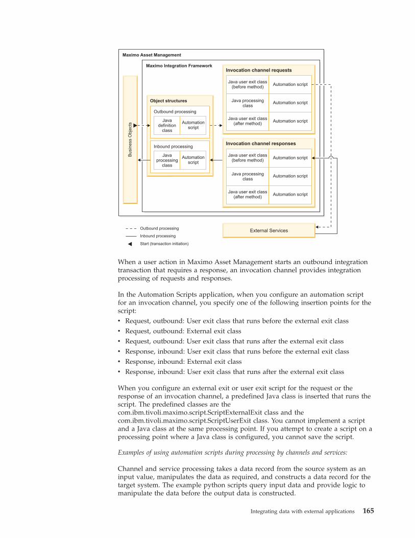
Maximo Asset Management
Maximo Integration Framework
Bu
sin
ess
Ob
jects
Object structures
Outbound processing
Javadefinition
class
Automationscript
Inbound processing
Javaprocessing
class
Automationscript
External Services
Invocation channel requests
Java user exit class(before method)
Java processingclass
Java user exit class(after method)
Automation script
Automation script
Automation script
Invocation channel responses
Java user exit class(before method)
Java processingclass
Java user exit class(after method)
Automation script
Automation script
Automation script
Outbound processing
Inbound processing
Start (transaction initiation)
When a user action in Maximo Asset Management starts an outbound integrationtransaction that requires a response, an invocation channel provides integrationprocessing of requests and responses.
In the Automation Scripts application, when you configure an automation scriptfor an invocation channel, you specify one of the following insertion points for thescript:v Request, outbound: User exit class that runs before the external exit classv Request, outbound: External exit classv Request, outbound: User exit class that runs after the external exit classv Response, inbound: User exit class that runs before the external exit classv Response, inbound: External exit classv Response, inbound: User exit class that runs after the external exit class
When you configure an external exit or user exit script for the request or theresponse of an invocation channel, a predefined Java class is inserted that runs thescript. The predefined classes are thecom.ibm.tivoli.maximo.script.ScriptExternalExit class and thecom.ibm.tivoli.maximo.script.ScriptUserExit class. You cannot implement a scriptand a Java class at the same processing point. If you attempt to create a script on aprocessing point where a Java class is configured, you cannot save the script.
Examples of using automation scripts during processing by channels and services:
Channel and service processing takes a data record from the source system as aninput value, manipulates the data as required, and constructs a data record for thetarget system. The example python scripts query input data and provide logic tomanipulate the data before the output data is constructed.
Integrating data with external applications 165
When Maximo Asset Management starts an integration transaction, the objectstructure provides an internal record data (irData) element to a publish channel oran invocation channel. Processing manipulates the irData element and constructsan external record data (erData) element before the message is forwarded to itsdestination. Invocation channel transactions can require a response from theexternal system. Response processing passes the erData element to the invocationchannel, which manipulates the response data and constructs the irData element.
When an external system starts an integration transaction, the message provides anerData element to an enterprise service. Processing manipulates the erData elementand constructs an irData element before the message is forwarded to the associatedobject structure. For messages that require a response, the object structure providesthe irData element to the enterprise service. Processing manipulates the data andconstructs the erData element that is forwarded to its destination.
The examples consist of simple scripts that can be used for test purposes. You canuse the data import and data export features in the External Systems application tostart transactions to test scripts.
Example: Script that changes the description of operating assets on outboundtransactions
In this scenario, the MXASSET object structure provides irData to the MYASSETpublish channel for processing. An automation script is configured to run on theexternal exit class of the publish channel. The script checks the status of the assetin the irData element. If the asset is in operating status, the script inserts a value inthe description field and prints a message to the log file. The erData element isthen constructed and is forwarded to the external system.if irData.getCurrentData("STATUS") == ’OPERATING’ :
irData.setCurrentData("DESCRIPTION","hello")print "MYASSET description change"
Example: Script that changes the description of operating assets on inboundtransactions
In this example, the MYASSET enterprise service processes an inbound message forthe MXASSET object structure. An automation script inserts a script on the externalexit class of the enterprise service. The script checks the status of the asset in theerData element. If the asset is in operating status, the script inserts a value in thedescription field and prints a message to the log file. The irData element is thenconstructed and is forwarded to the associated object structure for processing.if erData.getCurrentData("STATUS") == ’OPERATING’:
erData.setCurrentData("DESCRIPTION","hello inbound")print "MYASSET inbound description has changed"
Example: Script that changes the description of lines on a purchase order byusing an automation script variable
In this example, the MXPO object structure provides the irData element to theMYPO publish channel for processing. An automation script is configured to runon the external exit class of the publish channel. A literal value, world, is definedas an input variable on the automation script. The script queries the irData elementfor purchase orders that contain purchase order lines. The script numbers eachpurchase order line in a sequence that starts at 1, sets hello as the value in the
166 Integrating Data With External Applications
description field, and adds the input variable from the automation script. Thescript updates the parent purchase order before the erData element is constructedand forwarded to the external system.lines = irData.getChildrenData("POLINE")i = 0if lines is not None:
for value in lines:++iirData.setAsCurrent(lines,i);irData.setCurrentData("DESCRIPTION","hello"+world)
irData.setParentAsCurrent()
Example: Script that skips transactions based on the status of records
In this example, the MXPO object structure is sent to the MYPO2 publish channelfor processing. An automation script is configured to run on the user exit classbefore the external exit class runs. The script queries the irData element forpurchase orders with a status of WAPPR and skips the processing of thesepurchase orders.if irData.getCurrentData("STATUS") == ’WAPPR’ :
errorgroup = "iface"errorkey ="SKIP_TRANSACTION"
Example: Script that prints transaction information to a log file to assist withtroubleshooting
In this example, the MXASSET object structure provides irData to the MYASSET2publish channel for processing. An automation script is configured to run on theexternal exit class. The script queries the irData element for assets with a status ofoperating, prints transaction information to a log file, and constructs the erDataelement without making any changes. To print information about the transaction,you must set logging to debug. In the Logging application, the logger is set toautomation scripts and the logging level is set to DEBUG. In the AutomationScripts application, the logging level for the script is set to DEBUG.if irData.getCurrentData("STATUS") == ’OPERATING’ :
print "Test scriptvariable VAR_EXIT_IFACETYPE " + ifaceTypeprint "Test scriptvariable VAR_EXIT_IFACENAME " + ifaceNameprint "Test scriptvariable VAR_EXIT_EXTSYSTEM " + extSystemprint "Test scriptvariable VAR_EXIT_MESSAGETYPE " + messageTypeprint "Test scriptvariable VAR_EXIT_EXTSYSTEM " + extSystemprint "Test scriptvariable VAR_EXIT_OSNAME " + osNameprint "Test script
When an asset is exported, the following debugging information is printed to a logfile:18 Mar 2014 11:35:06:877 [DEBUG] [MXServer] [CID-MXSCRIPT-2022] execution completedfor cached compiled script PUBLISH.MYASSET.EXTEXIT.OUT for launch point nullTest script variable VAR_EXIT_IFACETYPE MAXIMOTest script variable VAR_EXIT_IFACENAME MYASSET2Test script variable VAR_EXIT_EXTSYSTEM MYEXTSYSTest script variable VAR_EXIT_MESSAGETYPE PublishTest script variable VAR_EXIT_OSNAME MXASSET
XSL mappingFor outbound transactions, you can implement an XSL file to manipulate the datathat is sent to the external system after Java exit processing is completed. Forinbound transactions, you can implement an XSL file to manipulate the data to beset to the object structure after Java exit processing is completed.
Integrating data with external applications 167
The XSL file is always called with the XML message that is output from the Javaexit processing. You can register the XSL file in the application EAR file under thebusinessobjects/classes/ directory or you can reference it using a directoryfilepath that is not part of the application EAR file.
Omit the .xsl file extension to register the file in the businessobjects/classes/psd/iface/xsl directory, for example:psdi.iface.xsl.mapping
Include the .xsl file extension to register the file in a file directory that isaccessible by the application server, for example:c:/psdi/iface/xsl/mapping.xsl
Interface table user exit classWhen you use interface tables to receive messages from an external system, youcan perform customization in the polling program that retrieves the data from theinterface table and sends data to the system.
The cron task manager runs the interface table polling program. TheIFACETABLECONSUMER cron task, has an optional EXITCLASS property whereyou can specify the fully qualified name of a Java exit class.
The Java data structure list represents the record from the interface tables, wherethe first element is always the action of the message. The remaining elements ofthe list are the mapped data structures and each map represents a row in theinterface table for each message. The keys in the map are the column names andthe values are the corresponding column values. All the column values areconverted to their translated string format before they are set in the map.
The EXITCLASS class must implement the psdi.iface.intertables.IfaceTbExitinterface and the following methods:v public void beforeQueue(long transid, String extSys, String ifaceName,
List data, Connection conn)
This method is called after the data is received from the interface table andbefore the data is inserted into one of the inbound queues.
v public void afterCommit(long transid, String extSys, String ifaceName,Connection conn)
This method is called after the data is inserted to an inbound queue and deletedfrom the interface queue table, and the database commit is done.
v public void afterRollback(long transid, String extSys, String ifaceName,Connection conn)
This method is similar to the afterCommit method but is called if the transactionis rolled back.
This class can perform the following processes:v Validate data.v Change external data by changing the IR record to be saved in the system.v Stop the transaction from being saved in the queue by throwing an exception. In
this case, the transaction remains in the MXIN_INTER_TRANS table with theerror message and is reprocessed.
v Stop the message from being sent to external system by throwing askip_transaction exception. In this case, message the system does not save themessage; the message is removed from the queue.
168 Integrating Data With External Applications
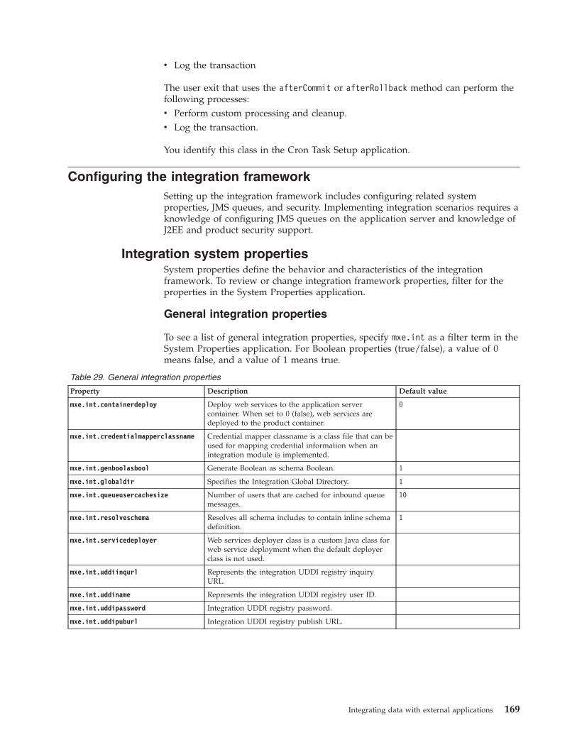
v Log the transaction
The user exit that uses the afterCommit or afterRollback method can perform thefollowing processes:v Perform custom processing and cleanup.v Log the transaction.
You identify this class in the Cron Task Setup application.
Configuring the integration frameworkSetting up the integration framework includes configuring related systemproperties, JMS queues, and security. Implementing integration scenarios requires aknowledge of configuring JMS queues on the application server and knowledge ofJ2EE and product security support.
Integration system propertiesSystem properties define the behavior and characteristics of the integrationframework. To review or change integration framework properties, filter for theproperties in the System Properties application.
General integration properties
To see a list of general integration properties, specify mxe.int as a filter term in theSystem Properties application. For Boolean properties (true/false), a value of 0means false, and a value of 1 means true.
Table 29. General integration properties
Property Description Default value
mxe.int.containerdeploy Deploy web services to the application servercontainer. When set to 0 (false), web services aredeployed to the product container.
0
mxe.int.credentialmapperclassname Credential mapper classname is a class file that can beused for mapping credential information when anintegration module is implemented.
mxe.int.genboolasbool Generate Boolean as schema Boolean. 1
mxe.int.globaldir Specifies the Integration Global Directory. 1
mxe.int.queueusercachesize Number of users that are cached for inbound queuemessages.
10
mxe.int.resolveschema Resolves all schema includes to contain inline schemadefinition.
1
mxe.int.servicedeployer Web services deployer class is a custom Java class forweb service deployment when the default deployerclass is not used.
mxe.int.uddiinqurl Represents the integration UDDI registry inquiryURL.
mxe.int.uddiname Represents the integration UDDI registry user ID.
mxe.int.uddipassword Integration UDDI registry password.
mxe.int.uddipuburl Integration UDDI registry publish URL.
Integrating data with external applications 169
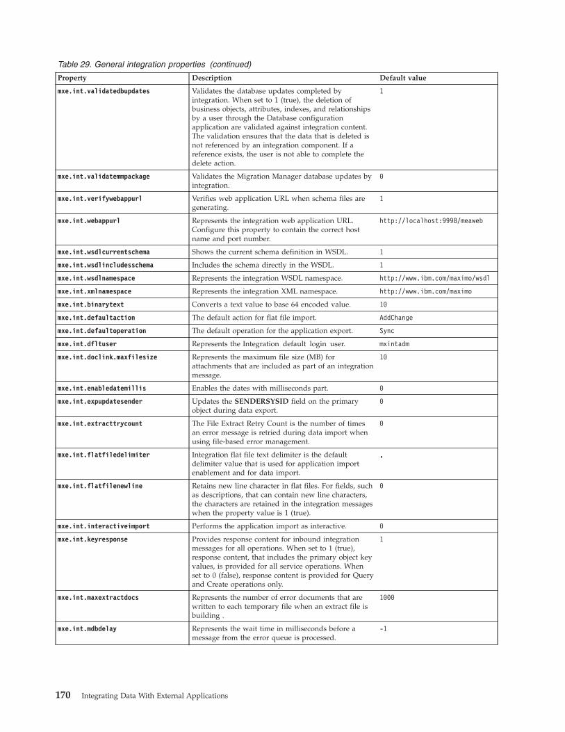
Table 29. General integration properties (continued)
Property Description Default value
mxe.int.validatedbupdates Validates the database updates completed byintegration. When set to 1 (true), the deletion ofbusiness objects, attributes, indexes, and relationshipsby a user through the Database configurationapplication are validated against integration content.The validation ensures that the data that is deleted isnot referenced by an integration component. If areference exists, the user is not able to complete thedelete action.
1
mxe.int.validatemmpackage Validates the Migration Manager database updates byintegration.
0
mxe.int.verifywebappurl Verifies web application URL when schema files aregenerating.
1
mxe.int.webappurl Represents the integration web application URL.Configure this property to contain the correct hostname and port number.
http://localhost:9998/meaweb
mxe.int.wsdlcurrentschema Shows the current schema definition in WSDL. 1
mxe.int.wsdlincludesschema Includes the schema directly in the WSDL. 1
mxe.int.wsdlnamespace Represents the integration WSDL namespace. http://www.ibm.com/maximo/wsdl
mxe.int.xmlnamespace Represents the integration XML namespace. http://www.ibm.com/maximo
mxe.int.binarytext Converts a text value to base 64 encoded value. 10
mxe.int.defaultaction The default action for flat file import. AddChange
mxe.int.defaultoperation The default operation for the application export. Sync
mxe.int.dfltuser Represents the Integration default login user. mxintadm
mxe.int.doclink.maxfilesize Represents the maximum file size (MB) forattachments that are included as part of an integrationmessage.
10
mxe.int.enabledatemillis Enables the dates with milliseconds part. 0
mxe.int.expupdatesender Updates the SENDERSYSID field on the primaryobject during data export.
0
mxe.int.extracttrycount The File Extract Retry Count is the number of timesan error message is retried during data import whenusing file-based error management.
0
mxe.int.flatfiledelimiter Integration flat file text delimiter is the defaultdelimiter value that is used for application importenablement and for data import.
,
mxe.int.flatfilenewline Retains new line character in flat files. For fields, suchas descriptions, that can contain new line characters,the characters are retained in the integration messageswhen the property value is 1 (true).
0
mxe.int.interactiveimport Performs the application import as interactive. 0
mxe.int.keyresponse Provides response content for inbound integrationmessages for all operations. When set to 1 (true),response content, that includes the primary object keyvalues, is provided for all service operations. Whenset to 0 (false), response content is provided for Queryand Create operations only.
1
mxe.int.maxextractdocs Represents the number of error documents that arewritten to each temporary file when an extract file isbuilding .
1000
mxe.int.mdbdelay Represents the wait time in milliseconds before amessage from the error queue is processed.
-1
170 Integrating Data With External Applications
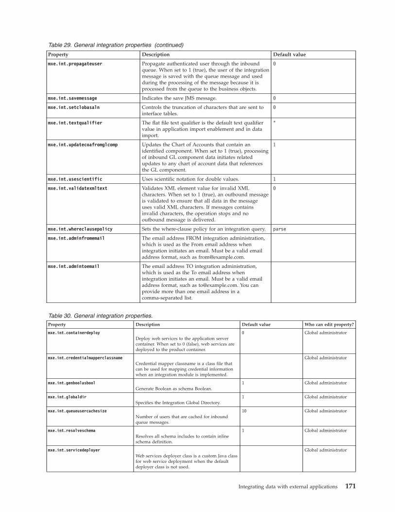
Table 29. General integration properties (continued)
Property Description Default value
mxe.int.propagateuser Propagate authenticated user through the inboundqueue. When set to 1 (true), the user of the integrationmessage is saved with the queue message and usedduring the processing of the message because it isprocessed from the queue to the business objects.
0
mxe.int.savemessage Indicates the save JMS message. 0
mxe.int.setclobasaln Controls the truncation of characters that are sent tointerface tables.
0
mxe.int.textqualifier The flat file text qualifier is the default text qualifiervalue in application import enablement and in dataimport.
"
mxe.int.updatecoafromglcomp Updates the Chart of Accounts that contain anidentified component. When set to 1 (true), processingof inbound GL component data initiates relatedupdates to any chart of account data that referencesthe GL component.
1
mxe.int.usescientific Uses scientific notation for double values. 1
mxe.int.validatexmltext Validates XML element value for invalid XMLcharacters. When set to 1 (true), an outbound messageis validated to ensure that all data in the messageuses valid XML characters. If messages containsinvalid characters, the operation stops and nooutbound message is delivered.
0
mxe.int.whereclausepolicy Sets the where-clause policy for an integration query. parse
mxe.int.adminfromemail The email address FROM integration administration,which is used as the From email address whenintegration initiates an email. Must be a valid emailaddress format, such as [email protected].
mxe.int.admintoemail The email address TO integration administration,which is used as the To email address whenintegration initiates an email. Must be a valid emailaddress format, such as [email protected]. You canprovide more than one email address in acomma-separated list.
Table 30. General integration properties.Property Description Default value Who can edit property?
mxe.int.containerdeployDeploy web services to the application servercontainer. When set to 0 (false), web services aredeployed to the product container.
0 Global administrator
mxe.int.credentialmapperclassnameCredential mapper classname is a class file thatcan be used for mapping credential informationwhen an integration module is implemented.
Global administrator
mxe.int.genboolasboolGenerate Boolean as schema Boolean.
1 Global administrator
mxe.int.globaldirSpecifies the Integration Global Directory.
1 Global administrator
mxe.int.queueusercachesizeNumber of users that are cached for inboundqueue messages.
10 Global administrator
mxe.int.resolveschemaResolves all schema includes to contain inlineschema definition.
1 Global administrator
mxe.int.servicedeployerWeb services deployer class is a custom Java classfor web service deployment when the defaultdeployer class is not used.
Global administrator
Integrating data with external applications 171
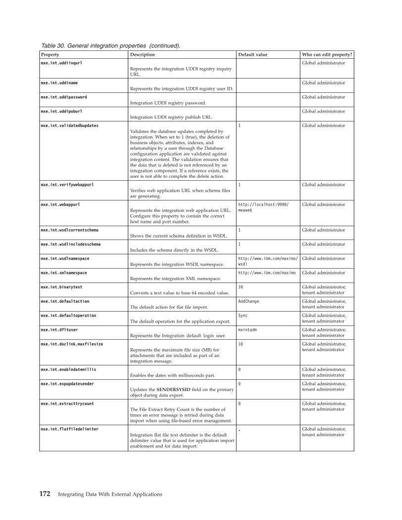
Table 30. General integration properties (continued).Property Description Default value Who can edit property?
mxe.int.uddiinqurlRepresents the integration UDDI registry inquiryURL.
Global administrator
mxe.int.uddinameRepresents the integration UDDI registry user ID.
Global administrator
mxe.int.uddipasswordIntegration UDDI registry password.
Global administrator
mxe.int.uddipuburlIntegration UDDI registry publish URL.
Global administrator
mxe.int.validatedbupdatesValidates the database updates completed byintegration. When set to 1 (true), the deletion ofbusiness objects, attributes, indexes, andrelationships by a user through the Databaseconfiguration application are validated againstintegration content. The validation ensures thatthe data that is deleted is not referenced by anintegration component. If a reference exists, theuser is not able to complete the delete action.
1 Global administrator
mxe.int.verifywebappurlVerifies web application URL when schema filesare generating.
1 Global administrator
mxe.int.webappurlRepresents the integration web application URL.Configure this property to contain the correcthost name and port number.
http://localhost:9998/meaweb
Global administrator
mxe.int.wsdlcurrentschemaShows the current schema definition in WSDL.
1 Global administrator
mxe.int.wsdlincludesschemaIncludes the schema directly in the WSDL.
1 Global administrator
mxe.int.wsdlnamespaceRepresents the integration WSDL namespace.
http://www.ibm.com/maximo/wsdl
Global administrator
mxe.int.xmlnamespaceRepresents the integration XML namespace.
http://www.ibm.com/maximo Global administrator
mxe.int.binarytextConverts a text value to base 64 encoded value.
10 Global administrator,tenant administrator
mxe.int.defaultactionThe default action for flat file import.
AddChange Global administrator,tenant administrator
mxe.int.defaultoperationThe default operation for the application export.
Sync Global administrator,tenant administrator
mxe.int.dfltuserRepresents the Integration default login user.
mxintadm Global administrator,tenant administrator
mxe.int.doclink.maxfilesizeRepresents the maximum file size (MB) forattachments that are included as part of anintegration message.
10 Global administrator,tenant administrator
mxe.int.enabledatemillisEnables the dates with milliseconds part.
0 Global administrator,tenant administrator
mxe.int.expupdatesenderUpdates the SENDERSYSID field on the primaryobject during data export.
0 Global administrator,tenant administrator
mxe.int.extracttrycountThe File Extract Retry Count is the number oftimes an error message is retried during dataimport when using file-based error management.
0 Global administrator,tenant administrator
mxe.int.flatfiledelimiterIntegration flat file text delimiter is the defaultdelimiter value that is used for application importenablement and for data import.
, Global administrator,tenant administrator
172 Integrating Data With External Applications
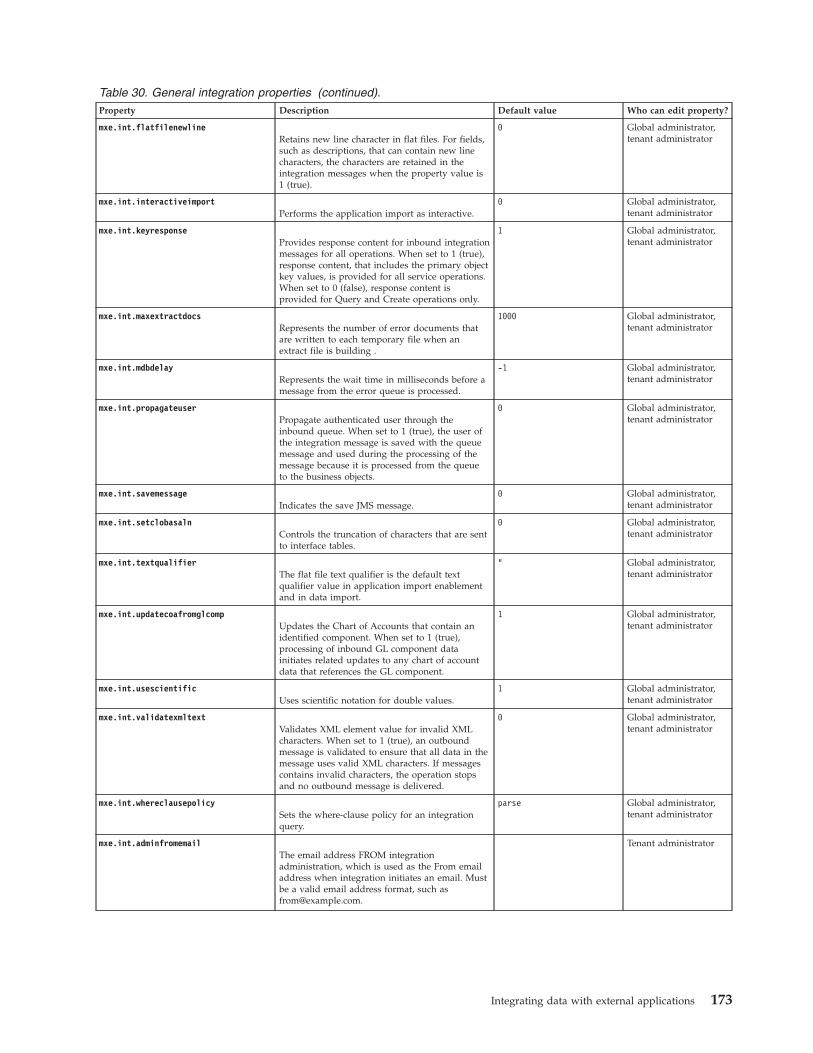
Table 30. General integration properties (continued).Property Description Default value Who can edit property?
mxe.int.flatfilenewlineRetains new line character in flat files. For fields,such as descriptions, that can contain new linecharacters, the characters are retained in theintegration messages when the property value is1 (true).
0 Global administrator,tenant administrator
mxe.int.interactiveimportPerforms the application import as interactive.
0 Global administrator,tenant administrator
mxe.int.keyresponseProvides response content for inbound integrationmessages for all operations. When set to 1 (true),response content, that includes the primary objectkey values, is provided for all service operations.When set to 0 (false), response content isprovided for Query and Create operations only.
1 Global administrator,tenant administrator
mxe.int.maxextractdocsRepresents the number of error documents thatare written to each temporary file when anextract file is building .
1000 Global administrator,tenant administrator
mxe.int.mdbdelayRepresents the wait time in milliseconds before amessage from the error queue is processed.
-1 Global administrator,tenant administrator
mxe.int.propagateuserPropagate authenticated user through theinbound queue. When set to 1 (true), the user ofthe integration message is saved with the queuemessage and used during the processing of themessage because it is processed from the queueto the business objects.
0 Global administrator,tenant administrator
mxe.int.savemessageIndicates the save JMS message.
0 Global administrator,tenant administrator
mxe.int.setclobasalnControls the truncation of characters that are sentto interface tables.
0 Global administrator,tenant administrator
mxe.int.textqualifierThe flat file text qualifier is the default textqualifier value in application import enablementand in data import.
" Global administrator,tenant administrator
mxe.int.updatecoafromglcompUpdates the Chart of Accounts that contain anidentified component. When set to 1 (true),processing of inbound GL component datainitiates related updates to any chart of accountdata that references the GL component.
1 Global administrator,tenant administrator
mxe.int.usescientificUses scientific notation for double values.
1 Global administrator,tenant administrator
mxe.int.validatexmltextValidates XML element value for invalid XMLcharacters. When set to 1 (true), an outboundmessage is validated to ensure that all data in themessage uses valid XML characters. If messagescontains invalid characters, the operation stopsand no outbound message is delivered.
0 Global administrator,tenant administrator
mxe.int.whereclausepolicySets the where-clause policy for an integrationquery.
parse Global administrator,tenant administrator
mxe.int.adminfromemailThe email address FROM integrationadministration, which is used as the From emailaddress when integration initiates an email. Mustbe a valid email address format, such [email protected].
Tenant administrator
Integrating data with external applications 173
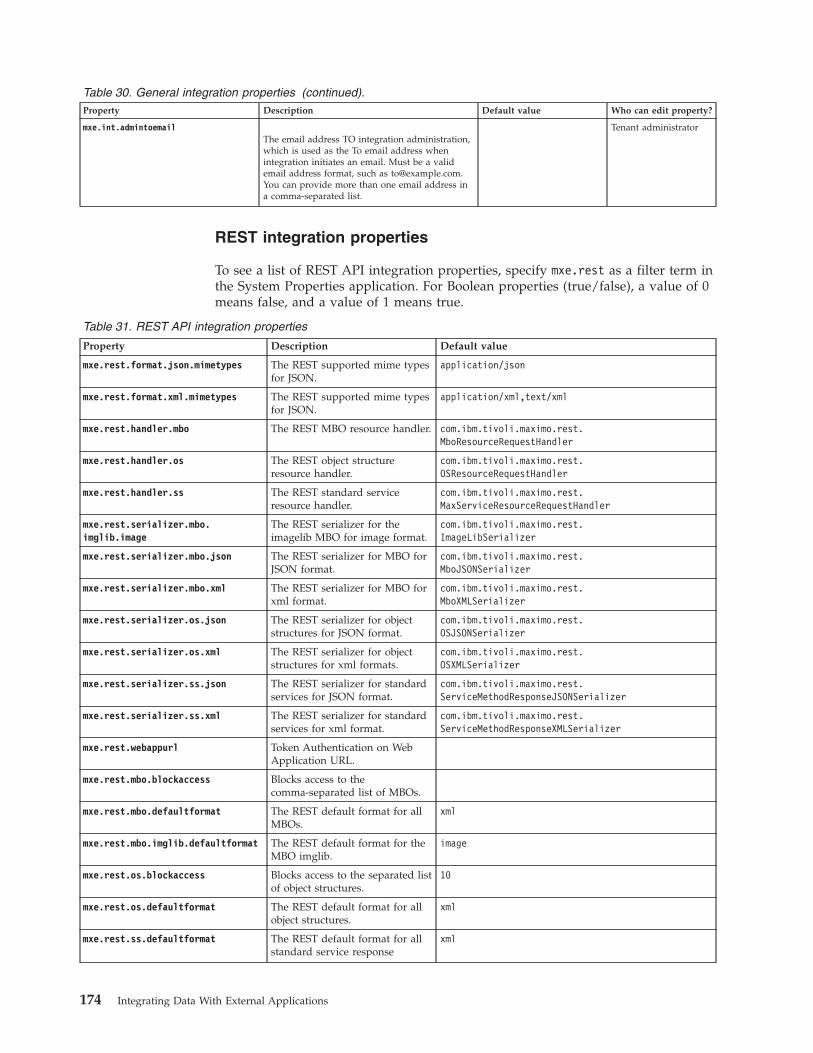
Table 30. General integration properties (continued).Property Description Default value Who can edit property?
mxe.int.admintoemailThe email address TO integration administration,which is used as the To email address whenintegration initiates an email. Must be a validemail address format, such as [email protected] can provide more than one email address ina comma-separated list.
Tenant administrator
REST integration properties
To see a list of REST API integration properties, specify mxe.rest as a filter term inthe System Properties application. For Boolean properties (true/false), a value of 0means false, and a value of 1 means true.
Table 31. REST API integration properties
Property Description Default value
mxe.rest.format.json.mimetypes The REST supported mime typesfor JSON.
application/json
mxe.rest.format.xml.mimetypes The REST supported mime typesfor JSON.
application/xml,text/xml
mxe.rest.handler.mbo The REST MBO resource handler. com.ibm.tivoli.maximo.rest.MboResourceRequestHandler
mxe.rest.handler.os The REST object structureresource handler.
com.ibm.tivoli.maximo.rest.OSResourceRequestHandler
mxe.rest.handler.ss The REST standard serviceresource handler.
com.ibm.tivoli.maximo.rest.MaxServiceResourceRequestHandler
mxe.rest.serializer.mbo.imglib.image
The REST serializer for theimagelib MBO for image format.
com.ibm.tivoli.maximo.rest.ImageLibSerializer
mxe.rest.serializer.mbo.json The REST serializer for MBO forJSON format.
com.ibm.tivoli.maximo.rest.MboJSONSerializer
mxe.rest.serializer.mbo.xml The REST serializer for MBO forxml format.
com.ibm.tivoli.maximo.rest.MboXMLSerializer
mxe.rest.serializer.os.json The REST serializer for objectstructures for JSON format.
com.ibm.tivoli.maximo.rest.OSJSONSerializer
mxe.rest.serializer.os.xml The REST serializer for objectstructures for xml formats.
com.ibm.tivoli.maximo.rest.OSXMLSerializer
mxe.rest.serializer.ss.json The REST serializer for standardservices for JSON format.
com.ibm.tivoli.maximo.rest.ServiceMethodResponseJSONSerializer
mxe.rest.serializer.ss.xml The REST serializer for standardservices for xml format.
com.ibm.tivoli.maximo.rest.ServiceMethodResponseXMLSerializer
mxe.rest.webappurl Token Authentication on WebApplication URL.
mxe.rest.mbo.blockaccess Blocks access to thecomma-separated list of MBOs.
mxe.rest.mbo.defaultformat The REST default format for allMBOs.
xml
mxe.rest.mbo.imglib.defaultformat The REST default format for theMBO imglib.
image
mxe.rest.os.blockaccess Blocks access to the separated listof object structures.
10
mxe.rest.os.defaultformat The REST default format for allobject structures.
xml
mxe.rest.ss.defaultformat The REST default format for allstandard service response
xml
174 Integrating Data With External Applications
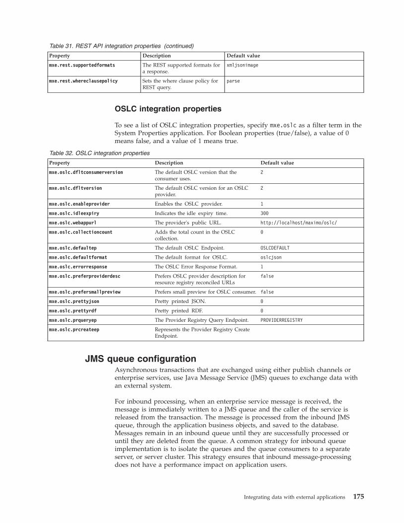
Table 31. REST API integration properties (continued)
Property Description Default value
mxe.rest.supportedformats The REST supported formats fora response.
xmljsonimage
mxe.rest.whereclausepolicy Sets the where clause policy forREST query.
parse
OSLC integration properties
To see a list of OSLC integration properties, specify mxe.oslc as a filter term in theSystem Properties application. For Boolean properties (true/false), a value of 0means false, and a value of 1 means true.
Table 32. OSLC integration properties
Property Description Default value
mxe.oslc.dfltconsumerversion The default OSLC version that theconsumer uses.
2
mxe.oslc.dfltversion The default OSLC version for an OSLCprovider.
2
mxe.oslc.enableprovider Enables the OSLC provider. 1
mxe.oslc.idleexpiry Indicates the idle expiry time. 300
mxe.oslc.webappurl The provider's public URL. http://localhost/maximo/oslc/
mxe.oslc.collectioncount Adds the total count in the OSLCcollection.
0
mxe.oslc.defaultep The default OSLC Endpoint. OSLCDEFAULT
mxe.oslc.defaultformat The default format for OSLC. oslcjson
mxe.oslc.errorresponse The OSLC Error Response Format. 1
mxe.oslc.preferproviderdesc Prefers OSLC provider description forresource registry reconciled URLs
false
mxe.oslc.prefersmallpreview Prefers small preview for OSLC consumer. false
mxe.oslc.prettyjson Pretty printed JSON. 0
mxe.oslc.prettyrdf Pretty printed RDF. 0
mxe.oslc.prqueryep The Provider Registry Query Endpoint. PROVIDERREGISTRY
mxe.oslc.prcreateep Represents the Provider Registry CreateEndpoint.
JMS queue configurationAsynchronous transactions that are exchanged using either publish channels orenterprise services, use Java Message Service (JMS) queues to exchange data withan external system.
For inbound processing, when an enterprise service message is received, themessage is immediately written to a JMS queue and the caller of the service isreleased from the transaction. The message is processed from the inbound JMSqueue, through the application business objects, and saved to the database.Messages remain in an inbound queue until they are successfully processed oruntil they are deleted from the queue. A common strategy for inbound queueimplementation is to isolate the queues and the queue consumers to a separateserver, or server cluster. This strategy ensures that inbound message-processingdoes not have a performance impact on application users.
Integrating data with external applications 175
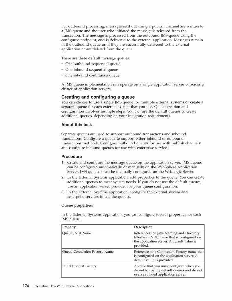
For outbound processing, messages sent out using a publish channel are written toa JMS queue and the user who initiated the message is released from thetransaction. The message is processed from the outbound JMS queue using theconfigured endpoint, and is delivered to the external application. Messages remainin the outbound queue until they are successfully delivered to the externalapplication or are deleted from the queue.
There are three default message queues:v One outbound sequential queuev One inbound sequential queuev One inbound continuous queue
A JMS queue implementation can operate on a single application server or across acluster of application servers.
Creating and configuring a queueYou can choose to use a single JMS queue for multiple external systems or create aseparate queue for each external system that you use. Queue creation andconfiguration involves multiple steps. You can use the default queues or createadditional queues, depending on your integration requirements.
About this task
Separate queues are used to support outbound transactions and inboundtransactions. Configure a queue to support either inbound or outboundtransactions, not both. Configure outbound queues for use with publish channelsand configure inbound queues for use with enterprise services.
Procedure1. Create and configure the message queue on the application server. JMS queues
can be configured automatically or manually on the WebSphere ApplicationServer. JMS queues must be manually configured on the WebLogic Server.
2. In the External Systems application, add properties to the queue. You can createadditional queues to meet system needs. If you do not use the default queues,use an application server provider for your queue configuration.
3. In the External Systems application, configure the external system andenterprise services to use the queues.
Queue properties:
In the External Systems application, you can configure several properties for eachJMS queue.
Property Description
Queue JNDI Name References the Java Naming and DirectoryInterface (JNDI) name that is configured onthe application server. A default value isprovided.
Queue Connection Factory Name References the Connection Factory name thatis configured on the application server. Adefault value is provided.
Initial Context Factory A value that you must configure when youdo not to use the default queues and do notuse a provided application server.
176 Integrating Data With External Applications
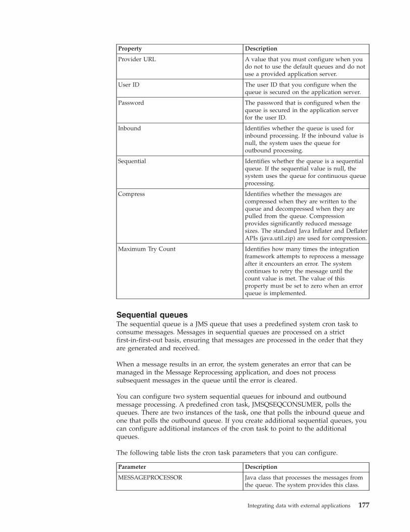
Property Description
Provider URL A value that you must configure when youdo not to use the default queues and do notuse a provided application server.
User ID The user ID that you configure when thequeue is secured on the application server.
Password The password that is configured when thequeue is secured in the application serverfor the user ID.
Inbound Identifies whether the queue is used forinbound processing. If the inbound value isnull, the system uses the queue foroutbound processing.
Sequential Identifies whether the queue is a sequentialqueue. If the sequential value is null, thesystem uses the queue for continuous queueprocessing.
Compress Identifies whether the messages arecompressed when they are written to thequeue and decompressed when they arepulled from the queue. Compressionprovides significantly reduced messagesizes. The standard Java Inflater and DeflaterAPIs (java.util.zip) are used for compression.
Maximum Try Count Identifies how many times the integrationframework attempts to reprocess a messageafter it encounters an error. The systemcontinues to retry the message until thecount value is met. The value of thisproperty must be set to zero when an errorqueue is implemented.
Sequential queuesThe sequential queue is a JMS queue that uses a predefined system cron task toconsume messages. Messages in sequential queues are processed on a strictfirst-in-first-out basis, ensuring that messages are processed in the order that theyare generated and received.
When a message results in an error, the system generates an error that can bemanaged in the Message Reprocessing application, and does not processsubsequent messages in the queue until the error is cleared.
You can configure two system sequential queues for inbound and outboundmessage processing. A predefined cron task, JMSQSEQCONSUMER, polls thequeues. There are two instances of the task, one that polls the inbound queue andone that polls the outbound queue. If you create additional sequential queues, youcan configure additional instances of the cron task to point to the additionalqueues.
The following table lists the cron task parameters that you can configure.
Parameter Description
MESSAGEPROCESSOR Java class that processes the messages fromthe queue. The system provides this class.
Integrating data with external applications 177
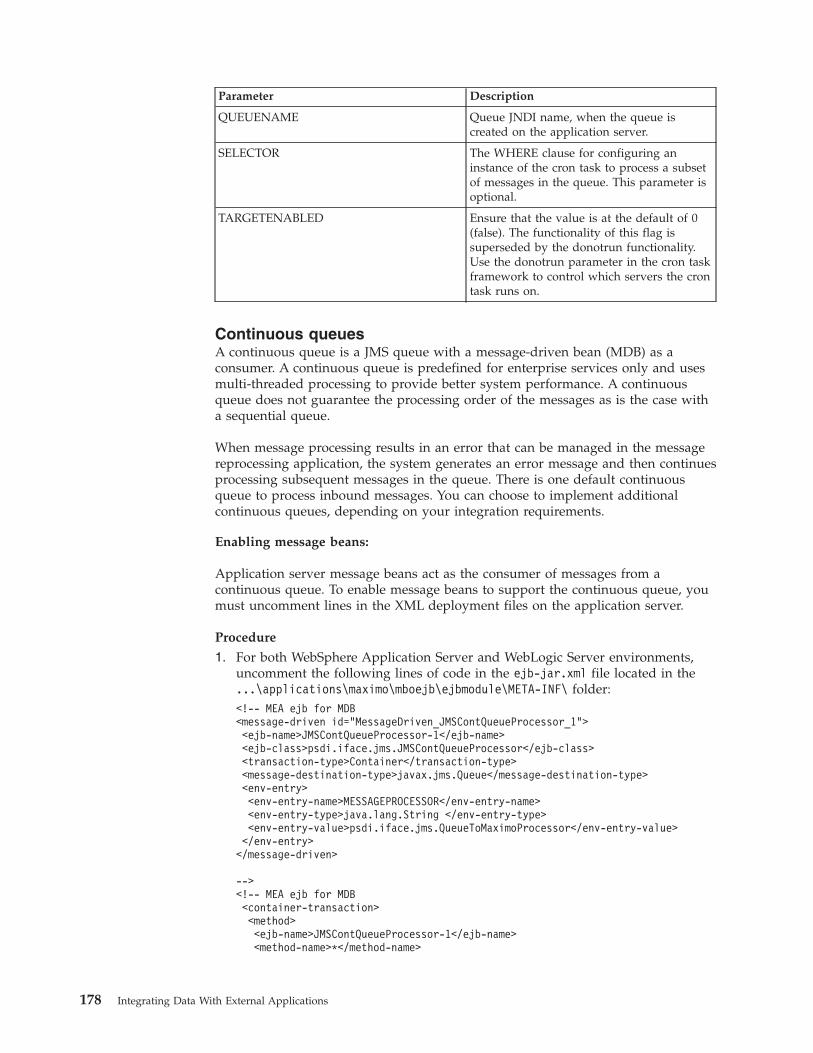
Parameter Description
QUEUENAME Queue JNDI name, when the queue iscreated on the application server.
SELECTOR The WHERE clause for configuring aninstance of the cron task to process a subsetof messages in the queue. This parameter isoptional.
TARGETENABLED Ensure that the value is at the default of 0(false). The functionality of this flag issuperseded by the donotrun functionality.Use the donotrun parameter in the cron taskframework to control which servers the crontask runs on.
Continuous queuesA continuous queue is a JMS queue with a message-driven bean (MDB) as aconsumer. A continuous queue is predefined for enterprise services only and usesmulti-threaded processing to provide better system performance. A continuousqueue does not guarantee the processing order of the messages as is the case witha sequential queue.
When message processing results in an error that can be managed in the messagereprocessing application, the system generates an error message and then continuesprocessing subsequent messages in the queue. There is one default continuousqueue to process inbound messages. You can choose to implement additionalcontinuous queues, depending on your integration requirements.
Enabling message beans:
Application server message beans act as the consumer of messages from acontinuous queue. To enable message beans to support the continuous queue, youmust uncomment lines in the XML deployment files on the application server.
Procedure
1. For both WebSphere Application Server and WebLogic Server environments,uncomment the following lines of code in the ejb-jar.xml file located in the...\applications\maximo\mboejb\ejbmodule\META-INF\ folder:<!-- MEA ejb for MDB<message-driven id="MessageDriven_JMSContQueueProcessor_1"><ejb-name>JMSContQueueProcessor-1</ejb-name><ejb-class>psdi.iface.jms.JMSContQueueProcessor</ejb-class><transaction-type>Container</transaction-type><message-destination-type>javax.jms.Queue</message-destination-type><env-entry><env-entry-name>MESSAGEPROCESSOR</env-entry-name><env-entry-type>java.lang.String </env-entry-type><env-entry-value>psdi.iface.jms.QueueToMaximoProcessor</env-entry-value></env-entry></message-driven>
--><!-- MEA ejb for MDB<container-transaction><method><ejb-name>JMSContQueueProcessor-1</ejb-name><method-name>*</method-name>
178 Integrating Data With External Applications
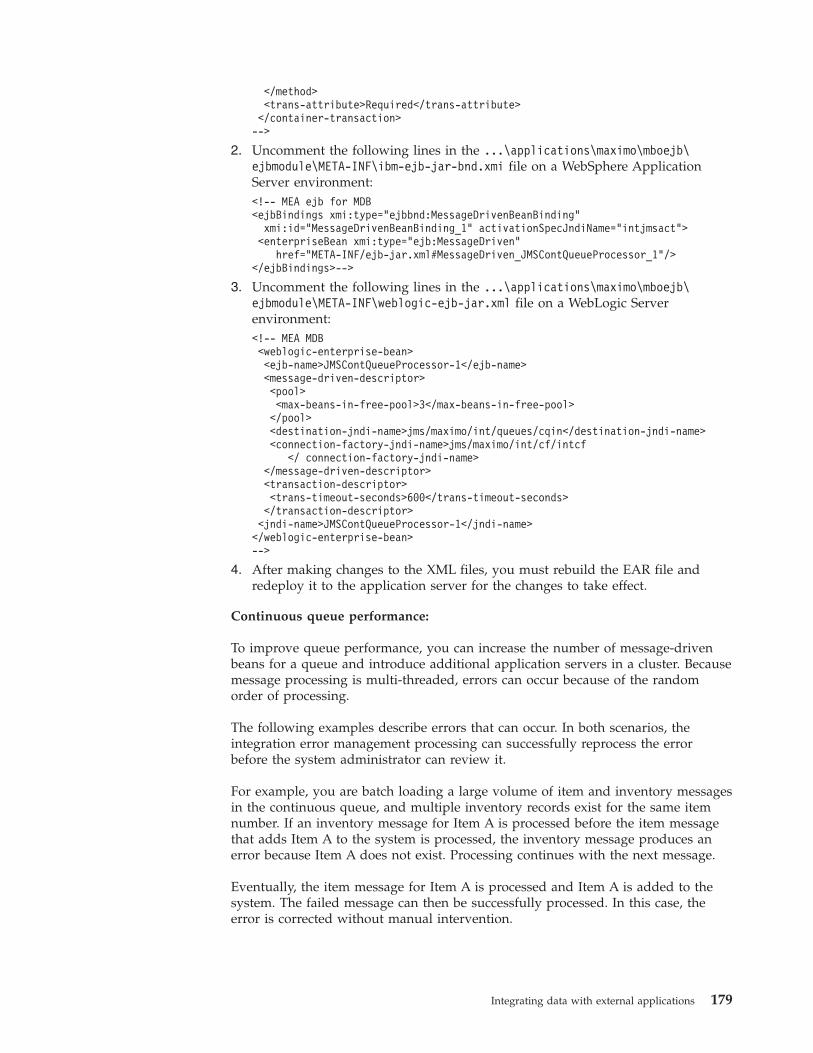
</method><trans-attribute>Required</trans-attribute></container-transaction>-->
2. Uncomment the following lines in the ...\applications\maximo\mboejb\ejbmodule\META-INF\ibm-ejb-jar-bnd.xmi file on a WebSphere ApplicationServer environment:<!-- MEA ejb for MDB<ejbBindings xmi:type="ejbbnd:MessageDrivenBeanBinding"
xmi:id="MessageDrivenBeanBinding_1" activationSpecJndiName="intjmsact"><enterpriseBean xmi:type="ejb:MessageDriven"
href="META-INF/ejb-jar.xml#MessageDriven_JMSContQueueProcessor_1"/></ejbBindings>-->
3. Uncomment the following lines in the ...\applications\maximo\mboejb\ejbmodule\META-INF\weblogic-ejb-jar.xml file on a WebLogic Serverenvironment:<!-- MEA MDB<weblogic-enterprise-bean><ejb-name>JMSContQueueProcessor-1</ejb-name><message-driven-descriptor><pool><max-beans-in-free-pool>3</max-beans-in-free-pool></pool><destination-jndi-name>jms/maximo/int/queues/cqin</destination-jndi-name><connection-factory-jndi-name>jms/maximo/int/cf/intcf
</ connection-factory-jndi-name></message-driven-descriptor><transaction-descriptor><trans-timeout-seconds>600</trans-timeout-seconds></transaction-descriptor><jndi-name>JMSContQueueProcessor-1</jndi-name></weblogic-enterprise-bean>-->
4. After making changes to the XML files, you must rebuild the EAR file andredeploy it to the application server for the changes to take effect.
Continuous queue performance:
To improve queue performance, you can increase the number of message-drivenbeans for a queue and introduce additional application servers in a cluster. Becausemessage processing is multi-threaded, errors can occur because of the randomorder of processing.
The following examples describe errors that can occur. In both scenarios, theintegration error management processing can successfully reprocess the errorbefore the system administrator can review it.
For example, you are batch loading a large volume of item and inventory messagesin the continuous queue, and multiple inventory records exist for the same itemnumber. If an inventory message for Item A is processed before the item messagethat adds Item A to the system is processed, the inventory message produces anerror because Item A does not exist. Processing continues with the next message.
Eventually, the item message for Item A is processed and Item A is added to thesystem. The failed message can then be successfully processed. In this case, theerror is corrected without manual intervention.
Integrating data with external applications 179
This type of situation can occur when you load related messages in the continuousqueue at the same time. Such a situation is more likely to occur when the volumeof transactions is high but also can occur whenever two messages process relateddata concurrently.
For example, two messages try to update the same system record at the same time.One message succeeds and the other fails. However, the error managementprocessing of the system must process the second message after the first update iscompleted.
Configuring message beans:
Server-specific extensions control the maximum number of beans that you cancreate.
Configuring message beans on WebSphere Application Server:
By default, the server is configured to have five message-driven beans.
Procedure
1. In the administrative console, select JMS activation specification.2. Select intjmsact.3. Specify a value in the Maximum Concurrent End Points field.
Configuring message beans on WebLogic Server:
By default, the WebLogic Server is configured to have three message-driven beans.
Procedure
1. Open the weblogic-ejb-jar.xml file in a text editor.2. Search for the following lines of code:
<pool><max-beans-in-free-pool>3</max-beans-in-free-pool></pool>
3. Replace the value 3 with a different value if required. Start with a relativelylow number of message-driven beans and monitor performance.
4. Modify the file to increase the number of message-driven beans incrementallyuntil you are satisfied with the processing performance of the messages in thecontinuous queue.
What to do next
If system performance is poor, you can resolve some system performance issues byclustering servers and isolating the inbound message processing to a specific servercluster.
Message caching:
Continuous queue processing uses the Maximum Batch Size property, under theActivation Specification definition, to control the number of messages receivedfrom the messaging engine in a single batch.
If three message-driven beans are enabled, and the batch size is 10, up to 30messages can be cached. Test with different values to ensure that the value thatyou set does not impact application users or server processes.
180 Integrating Data With External Applications
An unlimited number of messages can be processed when you set the MaximumBatch Size value to -1 on a WebLogic Server environment.
If you plan to use a WebSphere Application Server error queue, use the defaultvalue for the batch size.
Configuring an error queue for the continuous queue:
You can implement an error queue on the application server that moves a messageout of the main queue to a secondary queue when a message goes in error. Unlessyour integration scenario supports a very low volume of messages, configure anerror queue to support message processing through the continuous queue.
A continuous queue uses MDBs to consume messages. When a message goes inerror, the MDBs continue to consume the messages in error, even after themessages reach the maximum try count that is configured for processing. Thecontinuous selection of these messages consumes system resources and can slowdown, or even prevent, other messages from being processed. Configuring an errorqueue for the continuous queue helps to avoid performance delays or transactionbottlenecks by passing messages in error to a secondary queue.
Configuring an error queue on WebSphere Application Server:
You can configure a continuous queue to have a corresponding error queue. If amessage encounters an error, it is moved out of the continuous queue to the errorqueue when the number of retries set in the maximum failed deliveries parameteris met. The continuous queue then processes new queue messages.
About this task
The system provider must perform this task on behalf of the tenant.
Procedure
1. Configure an error queue destination within the same bus member where thecontinuous queue resides.
2. Configure the continuous queue destination definition to have an exceptiondestination. The exception destination must point to the error queue destinationthat you defined.
3. In the error queue, add an exception destination that points to itself. Errors inthe error queue move from the top of the error queue to the bottom of the errorqueue. Messages in error are continuously retried.
4. Open the ejb-jar.xml file in a text editor to enable the MDBDELAY property.To avoid excessive use of system resources during message reprocessing, theMDBDELAY property delays the processing of messages.
5. Uncomment the following lines of code and set an appropriate value:<env-entry><env-entry-name>MDBDELAY</env-entry-name><env-entry-type>java.lang.Long </env-entry-type><env-entry-value>30000</env-entry-value></env-entry>
The default value is 30 seconds (30000 milliseconds).6. Open the ibm-ejb-jar-bnd.xmi file and uncomment the following lines of code
to enable the message-driven beans on the error queue.
Integrating data with external applications 181
<!-- MEA MDB for error queue<ejbBindings xmi:type="ejbbnd:MessageDrivenBeanBinding"
xmi:id="MessageDrivenBeanBinding_1" activationSpecJndiName="intjmsacterr"><enterpriseBean xmi:type="ejb:MessageDriven"
href="META-INF/ejb-jar.xml#MessageDriven_JMSContQueueProcessor_2"/></ejbBindings>-->
Continuous queue errors on WebLogic Server:
The WebLogic Server queue has a redelivery delay property that can control howmessages in error are reprocessed. The redelivery delay property represents thetime between when the message reports an error and when the message isreprocessed.
You cannot view the message in the queue for the amount of time you specified inthe redelivery delay property. The redelivery delay improves system performance.Messages other than messages in error can be processed for the amount of timethat is defined in the redelivery delay property. The processing delay applies to themessage and not to the thread that processes the message.
If you set the batch size property to -1 (unlimited), and the redelivery delayproperty to 30 seconds (30,000 milliseconds), new messages can be processed in thequeue. Processing continues even when a large number of errors are beingreprocessed.
The same connection factory is used for both the sequential and continuousqueues. To avoid sequential consumer processing issues, set the redelivery delayvalue in the destination queue configuration. Do not set the connection factorylevel configuration.
If the number of times that a message in error is processed exceeds the configuredtry count, the message stops processing and is redirected for error management.
Alternatively you can implement an error queue. To implement an error queue,you must uncomment entries for the error queue in the ejb-jar.xml andweblogic-ejb-jar.xml files.
Queue message formatMessages that are loaded into the JMS queues by the integration framework havedefined components and formats The message body contains the XML messagethat is processed into the system or sent to the external system.
Message header
The message header can contain the JMS message ID and standard JMS headervalues.
Header Description
JMSMessageID A message ID that is generated by thesystem.
JMSRedelivered Identifies whether the message wasreprocessed.
182 Integrating Data With External Applications
Message properties
The properties contain the following properties from the JMS provider and theintegration framework. The integration framework properties are of the string datatype.
Property Description
MEAMessageID The message ID that is generated by theintegration framework.
destjndiname The name of the queue or topic that themessage is written to.
INTERFACE The name of the publish channel (outboundqueue) and the enterprise service (inboundqueue).
destination The external system name for outboundmessages.
SENDER The external system name for the inboundmessages.
USER The name of the user that is associated withthe inbound integration message. This valuecan be used for authorization security ifrequired.
compressed Indicates whether the message iscompressed. Values can be true or false; thedefault value is false.
The standard Java Inflater and Deflater APIs(java.util.zip) are used for compression.
uncompressed_length Stores the original message payload sizebefore compression. This value must complywith the int [xsd:int] schema type and ispresent only when the compressed propertyis set to true.
MSG_TRK_ENABLED Internal value.
MSG_OP_MODE The endpoint name for the outboundmessages. Fixed string MXJMS for inboundmessages.
MSG_TRK_STORE_MSG Internal value.
MSG_TRK_EXTSYS The external system name for outbound andinbound messages.
Msgkeyval A field name message key.
searchfieldval A comma-separated search field value.
msgoperation Indicates whether the publish channel orenterprise service contains a sync, create,update, or delete operation.
msgstatus Indicates whether the message has aRECEIVED, ERROR, DELETED, or aPROCESSED status value.
msgerrmsg Contains the exception message text.
Integrating data with external applications 183
Messages in text format:
Messages that are written to a queue by the integration framework are in byteformat by default. You can use the External Systems application to ensure thatmessages in text format are also supported.
To support messages in text format, select the Text check box in the Add/Modifyqueue window in the External Systems application. When a queue is configured tosupport messages in text format, all subsequent messages that are written to thequeue by an integration component are in the javax.jms.TextMessage format insteadof the default javax.jms.BytesMessage format.
When the queue is configured for messages in text format, the Text MessageEncoding field in the External Systems application identifies the encoding oftext-formatted messages in any of the inbound queues configured for the externalsystem. When no value is provided, messages are assumed to be encoded inUTF-8. Messages that are written to the outbound queue are always encoded withUTF-8.
Queue selectorsSelectors act as WHERE clauses in the JMS queue consumer. Selectors can beapplied to message headers and properties in either a continuous or a sequentialqueue.
The following table lists how you can use continuous selectors in the JMS queueconsumer.
Type of queue Where to identify selector
Sequential queue Specified as a property of the cron task.
Continuous queue Specified n the ejb-jar.xml code of themessage-driven bean.
Applying selectors splits a queue into smaller queues, each of which contains asubset of data that each cron task or message-driven bean uses. An error in onesubset of the data does not stop processing in the others in a sequential queue.
While selectors provide flexibility in separating the processing of transactions, theyimpair the performance of poll processing. Depending on the volume oftransactions, you can prefer to implement multiple queues instead of one queuewith multiple selectors. Multiple queues typically provide better performance.
You can add the following statement to the SELECTOR property of the SEQQINinstance of the JMSQSEQCONSUMER to instruct the cron task to process theMXPOInterface and MXPRInterface transactions from the corresponding externalsystem:SENDER=’EXTSYS1’ and INTERFACE in ('MXPOInterface’, 'MXPRInterface’)
Add the following content to the message bean configuration in the ejb-jar.xmlfile to instruct the message-driven bean to process the MXPOInterface andMXPRInterface transactions from the corresponding external system:<message-selector>
SENDER=’EXTSYS1’ AND INTERFACE IN ('MXPOInterface’, 'MXPRInterface’)</message-selector>
184 Integrating Data With External Applications
If two external systems send data to an inbound sequential queue, an error in anyrecord stops the processing of all transactions in that queue to maintain afirst-in-first-out processing order. Create multiple instances of a cron task, eachwith a selector that processes a different external system, to prevent an error in onesystem from stopping transactions from the second system.
Ensure that the where clauses in the selectors identify the mutually exclusive setsof transactions in a sequential queue. Include all the transactions that are insertedinto the queues to ensure that all messages are processed in a first-in-first-outorder.
Viewing and deleting messages in a JMS queueYou can view a list of the messages in a JMS queues, download these messages toview their content, and you can delete messages from configured queues. Whenviewing or deleting messages, you can apply a selector to limit the messagesreturned for processing.
About this task
Messages that are currently being processed to a continuous queue by amessage-driven bean or to a sequential queue by a JMS cron task are not availableto view or delete. You can deactivate the cron task to stop the processing ofmessages to a sequential queue. Message-driven beans continually processmessages and the number of messages being processed can vary. Unless youdisable message-driven beans, it is likely that not all messages can be viewed ordeleted. If you view or delete messages while message-driven beans are enabled, itis possible that not all messages are available for processing.
Procedure1. In the External Systems application, select the Add/Modify Queues action .2. Select a queue, and click either the View Queue Data button or the Delete
Queue Data button.3. Optional: If you select the View Queue Data option, you can specify a number
in the Count field to limit the number of records to view and you can checkthe Count Only field if you only want to see how many messages are currentlyin the queue.
4. Optional: Specify one of the following selectors if you want to filter the recordsreturned in either the View Queue Data window or in the Delete Queue Datawindow:
Option Description
MEAMessageID ID of the message (applies to inbound andoutbound messages).
INTERFACE The name of the enterprise service forinbound messages or the name of thepublish channel for outbound messages.
destination The name of the external system foroutbound queues only.
SENDER The name of the external system forinbound messages only.
USER The user provided with the message. Thisvalue is optional, and applies to inboundmessages only.
Integrating data with external applications 185
Selector values are case sensitive and you must enclose the value of the selectorin single quotes, for example INTERFACE='MXPERSONInterface'.
Configuring queues with WebSphere MQYou can use IBM WebSphere MQ to configure and manage queuing activities. Theintegration framework supports WebSphere MQ Version 6.Related concepts:“Messages in text format” on page 184Messages that are written to a queue by the integration framework are in byteformat by default. You can use the External Systems application to ensure thatmessages in text format are also supported.
Configuring JMS endpoints and handlers:
Outbound messages in a publish channel are placed into the default queue andyou must configure the JMS endpoint and handler to send the message toWebSphere MQ.
Procedure
1. Create an WebSphere MQ provider on the WebSphere Application Server andconfigure an integration endpoint to point to the message queue (MQ) providerby using:a. The destination JNDI name (DESTJNDINAME)b. The connection factory JNDI name (CONFACTORYJNDINAME)
2. Configure the endpoint to point to the WebSphere MQ by using:a. The destination JNDI name (DESTJNDINAME)b. The connection factory JNDI name (CONFACTORYJNDINAME)c. The provider URL (PROVIDERURL)d. The initial context factory (CONTEXTFACTORY)
Configuring integration queues and WebSphere MQ provider:
To replace integration framework queues with WebSphere MQ queues, configurethe queues on WebSphere Application Server and add these queue definitions inthe External Systems application.
Procedure
1. Create the JMS queue by defining an alternate provider to replace the defaultprovider.
2. Create a proxy queue on the WebSphere Application Server by using theWebSphere MQ provider that points to your message queue (MQ) serverqueue.
3. In the Add/Modify Queues dialog window in the External Systems application,add values to the Queue JNDI Name and Connection Factory fields to point tothe proxy queue and connection factory.
Results
Outbound messages that are destined for the default queue are delivered to themessage queue (MQ), and inbound messages are retrieved from the message queue(MQ).
186 Integrating Data With External Applications
Error managementThe integration framework supports a variety of message formats, protocols forexchanging messages, and both synchronous and asynchronous messageprocessing. The management of errors requires multiple options to meet the variedimplementation configurations that you can choose.
JMS queues are used by the integration framework as a staging mechanism forinbound and outbound messages. Queue error management is initiated when anerror condition is identified and you can view, correct, cancel, and reprocessproblematic messages.
Non-queue error managementWhen you start the synchronous processing of inbound or outbound integrationmessages, you are notified of any errors at the time of execution.
Non-queue error management is necessary if an error occurs when a synchronousmessage is being processed. For inbound messages, instead of relying on an errorqueue, the integration framework responds synchronously to the caller of theprocess with an error message. The calling application must receive the response,correct the error, and retry the transaction.
Use the system log to troubleshoot synchronous transaction errors. The system logcontains the processing exception that the integration framework issues to thecaller of the process.
Queue-based error managementYou can use the Message Reprocessing application to manage erroneous inboundand outbound asynchronous integration messages that use JMS queues.
Errors that occur when a message is sent from a queue to an external system aretypically caused by a communication failure or a problem with databaseconfiguration when writing to interface tables or files. Errors that occur duringinbound processing are typically a result of business rule validations or theinbound processing logic of the integration framework.
The sequential queue processes messages one at a time, in a first-in-first-outsequence. When the integration framework encounters an error in processing amessage in a sequential queue, inbound or outbound, the error managementmechanism is initiated and the message is flagged as having an error. Subsequentmessages in the queue are not processed until the message in error is resolved ordeleted. As a result, only a single error can exist in a sequential queue.
The continuous queue handles inbound processing only and processes messages ina multi-threaded mode. When an error occurs in the continuous queue, errormanagement is initiated and the message is flagged as having an error. Theintegration framework continues to process subsequent messages in the queue. Asa result, multiple errors can exist in a continuous queue.
Depending on your system configuration, the integration framework makes severalattempts to reprocess the message, for either type of queue, before determiningthat an error requires intervention. The system also performs the followingactivities when encountering an error:v Sends a notification to a specified email account, informing the recipient that an
error occurred. On an IBM WebSphere Application Server environment, the
Integrating data with external applications 187
integration framework sends an additional email message to the specified emailaccount each time that you successfully restart your application server.
v Creates a record in the Message Reprocessing application. Creates a record thatcan be viewed in the Message Reprocessing application. This record includes themessage that was placed in the queue.
Configuring error managementTo configure error management, you must configure system properties andconfigure the external system.
Configure error management properties:
Before you use the integration framework, configure properties in the SystemProperties application.
Procedure
1. Filter for the mxe.int.adminfromemail property and specify an email address,such as [email protected]. This address appears in error notificationsthat are submitted by the integration framework. Some SMTP servers requirethis address to be a valid email address format; some servers accept any value.
2. Filter for the mxe.int.admintoemail property and specify one or more emailaddresses to receive notification of message processing errors. Use commas todelimit several email addresses. You can optionally use the email addressproperty at the queue level to override the administrator address. Use thisoption if you want to specify different email addresses for each queue. If youdo not configure an email address, no email notification is sent when queueprocessing errors occur.
3. Filter for the mail.smtp.host property and specify an SMTP server if none hasbeen configured. This property is not unique to the integration framework, andcan be configured for other applications.
Configuring error management on the external system:
Configure the external system to handle error management.
Procedure
1. In the External Systems application, specify an appropriate value in theMaximum Try Count field. There is no limit to the number of times that thesystem retries the transaction. After the first unsuccessful attempt to process thetransaction, the system administrator receives a notification, and a message iswritten to an error file. This value is typically set to 0 for outbound queues.
2. Specify a value in the E-mail Address field if you want error notificationmessages to be sent to different addresses for each queue. You can entermultiple addresses, delimited with a comma (,). The value in this propertyoverrides the value in the administrator email address property. If no value isspecified, email notifications are sent to the email addresses that are specifiedfor the administrator email address property.
3. Click Save.
Error notificationWhen an inbound or outbound transaction results in an error in a queue, an emailnotification is sent to the system administrator only if no other unresolved errorsare waiting in the same queue. If multiple errors exist in the queue, the systemadministrator must resolve all of them before notification of new errors is sent.
188 Integrating Data With External Applications
An email error message includes a Java error stack trace.
The same notification process is used for all errors, for continuous and sequentialqueues, for inbound and outbound messages, and regardless of whether thesystem is running in a clustered or non-clustered environment.
The following example describes error notification for a continuous inbound queuecontains ten messages. The first four messages are processed successfully and anerror occurs on the fifth message. Depending on the value you set for theMaximum Try Count property for the external system, the message can be triedone or more times. If the message continues to cause an error, an email notificationis sent to the system administrator and subsequent messages in the queue areprocessed. If another error occurs in the seventh message, another emailnotification is not sent if the system administrator has not resolved the originalerror. If the system administrator resolved the original error and no errors arepending, a new email notification is sent.
If the error is encountered in a sequential queue, processing is the same as in acontinuous queue except that the system does not process subsequent messagesuntil the message with the original error is resolved.
Multiple errors can exist only in the continuous inbound queue. In a clusteredenvironment, the system administrator can receive one email error notification perapplication server, depending upon the timing of the transactions in error.
An uncommon exception condition can occur for outbound messages when amessage is saved to the queue but the commit of the transaction to the queue fails.This exception can occur because a database connection to the JMS data store isnot available. If this exception occurs, a notification is sent and the message inerror is visible in the Message Reprocessing application with a status of eitherJMSERROR or SAVED. Because the message was not saved successfully in thequeue, you cannot set the message status to RETRY, but you can process themessage from the application.
Message reprocessingIn the Message Reprocessing application, you can manage messages that areflagged with an error, including changing the message status, correcting themessage, or deleting it from the database.
If message tracking is enabled, use the Message Tracking application to determinewhich tracked messages are flagged with an error. If message tracking is notenabled, you can check for transaction errors in the Message Reprocessingapplication.
Message status values:
To change the status of a message, select the Change Status action in the MessageReprocessing application. The system designates a status to each message toindicate whether it is ready for processing.
A message can have a status of RETRY or HOLD:
Status Description
RETRY The message is ready to be reprocessed bythe system.
Integrating data with external applications 189
Status Description
HOLD The message is not ready to be reprocessedby the system.
The RETRY status is the default status for messages that are flagged with an error.Until you correct the processing problem, the system continues to reprocess themessage according to the configured queue retry count. When the retry countcondition is met, the system changes the messages status to HOLD.
You can halt message reprocessing by changing the message status to HOLD. Ahold status prevents the system from reprocessing the flagged message and fromupdating the system database tables.
Error XML messages:
You can review the XML message that is generated when an error occurs and youcan modify the content of the message.
When you manage an error in the Message Reprocessing application, you can thesee the following information:v The Error Data field contains the error message.v The message content contains the original message that was placed in the queue
and is causing an error. You can edit this element.v If available, the internal record contains the XML representation of the message
at the time that the error occurred. You cannot edit the internal record but youcan use it to view if integration processing changed the original message beforethe error occurred.
The internal record represents the object structure that was created duringenterprise service and user exit processing. An internal record is available only forinbound transactions, and only when enterprise service and user exit processingcomplete successfully. If an internal record is available, it is provided forinformation only and you cannot change it.
Following is an example of an error XML message:<?xml version="1.0" encoding="UTF-8"?>
<SyncMXPERSON xmlns="http://www.ibm.com/maximo"xmlns:xsi="http://www.w3.org/2001/XMLSchema-instance"creationDateTime="2014-04-22T14:04:03-04:00"transLanguage="EN" baseLanguage="EN" messageID="11798570432187483"maximoVersion="7 6" event="1" messageid="11798570432652428">
<MXPERSONSet><PERSON action="Update">...</PERSON></MXPERSONSet></SyncMXPERSON>
Following is an example of an internal record XML message:<?xml version="1.0" encoding="UTF-8"?>
<SyncMXPERSON xmlns="http://www.ibm.com/maximo"xmlns:xsi="http://www.w3.org/2001/XMLSchema-instance"creationDateTime="2014-04-22T14:04:03-04:00"transLanguage="EN" baseLanguage="EN" messageID="11798570432187483"maximoVersion="7 6" event="1" messageid="11798570432652428">
190 Integrating Data With External Applications
<MXPERSONSet><PERSON action="Update">...</PERSON></MXPERSONSet></SyncMXPERSON></IR></ERROR>
Critical errors:
Critical errors are processing exceptions that the integration framework errorcorrection process cannot retry.
Transaction processing exceptions can occur when incorrect data, such as a specialcharacter, is present in the XML file. To correct a critical error, you remove theincorrect data from the error XML message. You can see incorrect data that isassociated with a critical error in the main tab of the Message Reprocessingapplication.
Correcting errors:
In the Message Reprocessing application, you can either reprocess a message thatis in error, or you can delete the message from the database.
Reprocessing an edited message:
You can view, modify, and reprocess messages in the Message Reprocessingapplication. After you edit the error XML message, you can save or cancel thechanges without reprocessing the message.
About this task
You can edit only those messages that have a HOLD status. If the message has aRETRY status, the content of the message is read-only.
Procedure
1. In the Message Reprocessing application, select the message that you want tomodify and click the Message Details icon.
2. In the Error Data window, make any necessary changes to the message.3. Click Process if you want to reprocess the message. You can click Save to save
the changes without reprocessing the message or you can click Cancel todiscard any changes you made.
Results
If the processing is successful, the Message Reprocessing application performs thefollowing tasks:v Deletes the record in the error message table.v Updates the DELETEFLAG, CHANGE BY, and CHANGE DATE attributes in the
error status table
Integrating data with external applications 191
What to do next
In the Message Details window, refresh the list of messages that are flagged withan error. If the message was successfully reprocessed, it is dropped from the list.
Deleting messages:
You can delete messages from the error message queue. After you delete amessage, it cannot be reprocessed.
Procedure
1. In the Message Reprocessing application, select the message records that youwant to delete.
2. Select the Delete Message action.3. Click OK.
Results
When a message is deleted, the record is deleted from the MAXINTERRORMSGand MAXINTERROR tables. The application refreshes the result set and omits thedeleted message listing on the main tab of the Message Reprocessing application.
Refresh messages:
You can use the Refresh icon in the Message Reprocessing application to updatethe message list. When you refresh the message list, you can check on the status ofa specific message listings.
If the message reprocessing was successful, the application omits the applicablemessage listings. If you delete a message, the application omits the deletedmessage listing.
Error management with file-based data importThe integration framework supports error management with the MessageReprocessing application which allows you to review, correct, reprocess, and deletemessages that go in error when processed from an inbound queue. When data isimported from an XML file or a flat file, a second option is available that manageserrors using a downloaded file instead of the Message Reprocessing application.
File-based error management is beneficial when you import a large number ofmessages that can cause a large number of errors. Managing a large number oferrors in a file format can be easier and quicker than managing them individuallyin the Message Reprocessing application.Related concepts:“Exporting and importing file-based data” on page 218The integration administrator can initiate export and import data from within theExternal Systems application to support, for example, integrating data using files.The import process includes the ability to preview a data load from a file tovalidate the data prior to saving it to the database. The import process alsoincludes an option to manage errors that result from file loading in the same fileformat as the imported file
192 Integrating Data With External Applications
File-based error management:
You can use file-based error management with the data import feature. File-basederror management provides the ability to identify all integration messages flaggedwith an error and download a complete file that contains all errors. Thedownloaded file is in a format that is consistent with the file that was used for theimport.
To configure file-based error management, in the Data Import window, select theFile-based Error Management check box.
When you select the File-based Error Management check box and leave theImport Preview check box cleared, you receive a system message after the inboundmessages are processed successfully to the queue.
Inbound processing logic identifies processing errors on any of the messages in thesource file and makes these failed messages available for download in areprocessable file. The Message Reprocessing application provides a facility todownload the reprocessable file.
Selecting the File-based Error Management check box means that any integrationmessages flagged with an error are available only in the reprocessable file and arenot displayed in the messages section of the Message Reprocessing application.
Configuring error management in data import cron tasks:
You can set the ISFILEEXTRACT parameter in the XMLFILECONSUMER andFLATFILECONSUMER cron tasks to identify the error management mechanismthat you want to use.
The following table contains the possible values for the ISFILEEXTRACT parameter:
Value Error management mechanism
0 Error management is handled in theMessage Reprocessing application.
1 File-based error management is handled inthe Data Import window and in thereprocessable file.
File-based error management means that any integration messages flagged with anerror are available only in the reprocessable file and are not displayed in themessages section of the Message Reprocessing application.
Information extracted by file-based error management:
File-based error management provides the ability to download a reprocessable filethat contains all of the error messages that originated from a single input file.
The following table contains the information available in the Error Extract sectionof the Message Reprocessing application.
Field Description
Import file Name of the source file that generated the reprocessable file.
Integrating data with external applications 193
Field Description
Enterpriseservice
Name of the enterprise service that was used to import the source file.
Externalsystem
Name of the external system that was used to import the source file.
Import date Date and time when the data import process initiated processing of thesource file.
Importedcount
Total number of messages imported from the original source file.
Processedcount
Number of messages processed successfully.
Error count Number of messages that have errors.
File format Format of the source file.
Available toextract
Identifies whether the inbound processing of the source file has completed.
Extract icon Action button that initiates the file download process. To assure that thesource file has been completely processed by the import mechanism, files areonly available for download when the sum of error count and processedcount is equal to the imported count.
Delete icon Action button that deletes the selected record from the Error Extract table.You can only delete table records if the sum of the error count andprocessed count is equal to the imported count.
Downloading reprocessable files:
You can download a reprocessable file and fix the processing errors identified inthe file. You can then attempt to reload the reprocessable files without removingany of the error message description information that is contained in the file.
Procedure
1. In the Message Reprocessing application, identify the source file from whichyou will be downloading its corresponding errors.
2. Verify that the source file has been fully processed by the data import process.The sum of the error count field and the processed count field must equal theimported count field.
3. Click the Download icon.4. Save the reprocessable file to your client or to an accessible file server location.
Reprocessable file format:
When you download the reprocessable file, it is provided in the same format as theoriginal input file. If you use the flat file format, the file uses the same delimiterand text qualifier. The default file name for the reprocessable file is<UniqueFileIdentifier>_<OriginalFileName>.<OriginalFileExtension>
Example of an XML reprocessable file
A reprocessable file based on an XML file, includes an additional element in themain MBO of the original object structure. For example, a reprocessable filegenerated based on MXASSET information includes the MAXINTERRORMSGelement as part of the asset elements.
194 Integrating Data With External Applications
<?xml version="1.0" encoding="UTF-8"?><SyncMXASSET xmlns="http://www.ibm.com/maximo" transLanguage="EN">
<MXASSETSet><ASSET>
<ANCESTOR /><ASSETID>94</ASSETID><ASSETNUM>THREE_T2002</ASSETNUM><ASSETTAG /><ASSETTYPE />.........<WARRANTYEXPDATE>2020-12-24T00:00:00-05:00</WARRANTYEXPDATE><YTDCOST>0.0</YTDCOST><MAXINTERRORMSG>
The following error occurred while processing ASSET.BMXAA4147E -Item set error1 does not exist.
</MAXINTERRORMSG></ASSET>.........
</MXASSETSet></SyncMXASSET>
Example of flat format reprocessable file
Reprocessable files that follow a flat file structure include an additional column.For example, a reprocessable file generated based on MXASSET informationincludes the MAXINTERROR column at the end of the original record structure:EXTSYS1,MXASSETInterface,,ENASSETNUM,AS_DESCRIPTION,AS_DESCRIPTION_LD,HIERARCHYPATH,AS_SITEID,MAXINTERRORMSGT-SP500_error,autospray,,,TEXAS,The following error occurred while processing ASSET.BMXAA4049E -The value specified T-SP500_error exceeds the maximum field length.
Deleting reprocessable files:
You can permanently delete data that is available to reprocess as a file.
Procedure
1. In the Message Reprocessing application, identify the row of reprocessable datathat you want to delete.
2. Click the Delete icon.
Interface table error managementInterface tables can be used for inbound and outbound data exchange. Errors canoccur when writing inbound data from an interface table to a queue or outbounddata from a queue to an interface table.
If an error is encountered by the cron task that pulls an outbound message from aqueue, the message remains in the queue until the error condition is addressed.Errors may occur for the following reasons:v The interface table does not exist.v There is database error due to lack of space.v The message content, as defined by the object structure, was altered but the
interface table was not recreated to reflect the new message format.
Integrating data with external applications 195
When an outbound message reaches an interface table, it is the responsibility of theexternal application to retrieve that data and manage errors based on theirintegration implementation.
The cron task that writes inbound messages to a queue can encounter errors forthe following reasons:v The JMS queue is deactivated or free space is not available.v The enterprise service or external system name is not valid.v The enterprise service is not enabled for the external system.v The external system is not enabled.
When an error occurs during inbound interface table processing, the pollingprogram writes the exception trace in the IMPORTMESSAGE column of theMXIN_INTER_TRANS queue table. For the first error in the MXIN_INTER_TRANSqueue table, the system sends an email notification to the administrator. You canresolve the error condition by updating the row of data in MXIN_INTER_TRANS,for example, correcting the value of the external system name, or by updating theconfiguration data in the application, for example, marking the enterprise serviceas enabled.
After the cron task processes subsequent records in the MXIN_INTER_TRANSqueue table, it switches to an idle state that is based on the defined cron taskprocessing intervals. When processing resumes, the cron task tries to process therecords in error, as well as new records added to the MAX_INTER_TRANS queuetable.
After sending an error notification, the cron task does not send notification ofadditional errors if the queue table contains one transaction that is marked in error.It is assumed that the person who was notified of the initial error sees and correctsadditional errors when the queue table is examined. After all current errors arecorrected, the cron task sends a notification when it encounters a new error.
Any errors that occur after the cron task successfully writes an interface tablemessage to an inbound queue are managed by the error handling process for thequeues.
Common causes of errorsErrors when processing messages in the outbound queue occur because there is aproblem delivering a message to the endpoint that is specified for the externalsystem. Errors when processing messages in an inbound queue are typicallyrelated to a business rule validation or in the inbound processing of the enterpriseservice.
For outbound processing, typical problems are disruptions of the communicationlink to the external application, issues with the database table space, or file spaceissues in the external application. To resolve an outbound error, you typically donot need to modify the XML message.
The following table describes the most common message errors that you canencounter and provides suggestions for correcting them. Correcting an error in theXML message can create a mismatch in data between the sending and receivingsystems.
196 Integrating Data With External Applications
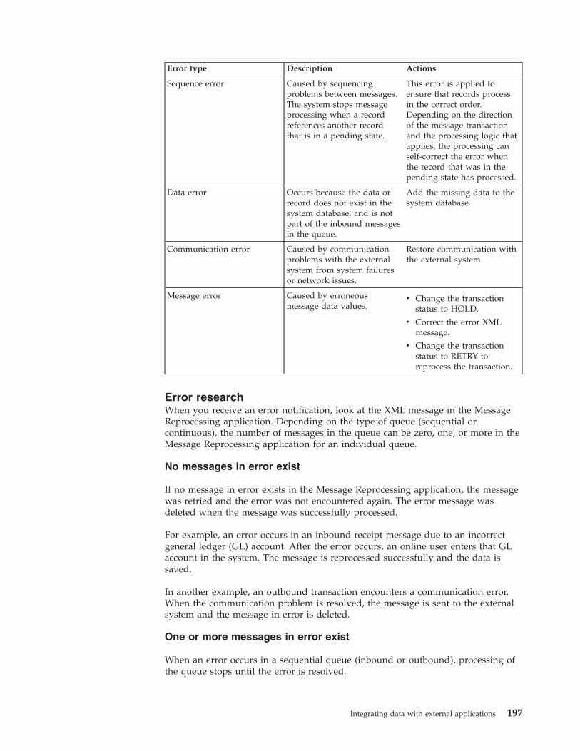
Error type Description Actions
Sequence error Caused by sequencingproblems between messages.The system stops messageprocessing when a recordreferences another recordthat is in a pending state.
This error is applied toensure that records processin the correct order.Depending on the directionof the message transactionand the processing logic thatapplies, the processing canself-correct the error whenthe record that was in thepending state has processed.
Data error Occurs because the data orrecord does not exist in thesystem database, and is notpart of the inbound messagesin the queue.
Add the missing data to thesystem database.
Communication error Caused by communicationproblems with the externalsystem from system failuresor network issues.
Restore communication withthe external system.
Message error Caused by erroneousmessage data values.
v Change the transactionstatus to HOLD.
v Correct the error XMLmessage.
v Change the transactionstatus to RETRY toreprocess the transaction.
Error researchWhen you receive an error notification, look at the XML message in the MessageReprocessing application. Depending on the type of queue (sequential orcontinuous), the number of messages in the queue can be zero, one, or more in theMessage Reprocessing application for an individual queue.
No messages in error exist
If no message in error exists in the Message Reprocessing application, the messagewas retried and the error was not encountered again. The error message wasdeleted when the message was successfully processed.
For example, an error occurs in an inbound receipt message due to an incorrectgeneral ledger (GL) account. After the error occurs, an online user enters that GLaccount in the system. The message is reprocessed successfully and the data issaved.
In another example, an outbound transaction encounters a communication error.When the communication problem is resolved, the message is sent to the externalsystem and the message in error is deleted.
One or more messages in error exist
When an error occurs in a sequential queue (inbound or outbound), processing ofthe queue stops until the error is resolved.
Integrating data with external applications 197
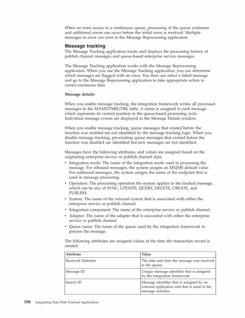
When an error occurs in a continuous queue, processing of the queue continuesand additional errors can occur before the initial error is resolved. Multiplemessages in error can exist in the Message Reprocessing application.
Message trackingThe Message Tracking application tracks and displays the processing history ofpublish channel messages and queue-based enterprise service messages.
The Message Tracking application works with the Message Reprocessingapplication. When you use the Message Tracking application, you can determinewhich messages are flagged with an error. You then can select a failed messageand go to the Message Reprocessing application to take appropriate action tocorrect erroneous data.
Message details:
When you enable message tracking, the integration framework writes all processedmessages to the MAXINTMSGTRK table. A status is assigned to each messagewhich represents its current position in the queue-based processing cycle.Individual message events are displayed in the Message Details window.
When you enable message tracking, queue messages that existed before thefunction was enabled are not identified by the message tracking logic. When youdisable message tracking, pre-existing queue messages that existed before thefunction was disabled are identified but new messages are not identified.
Messages have the following attributes, and values are assigned based on theoriginating enterprise service or publish channel data:v Integration mode: The name of the integration mode used in processing the
message. For inbound messages, the system assigns an MXJMS default value.For outbound messages, the system assigns the name of the endpoint that isused in message processing.
v Operation: The processing operation the system applies to the tracked message,which can be any of SYNC, UPDATE, QUERY, DELETE, CREATE, andPUBLISH.
v System: The name of the external system that is associated with either theenterprise service or publish channel.
v Integration component: The name of the enterprise service or publish channel.v Adapter: The name of the adapter that is associated with either the enterprise
service or publish channel.v Queue name: The name of the queue used by the integration framework to
process the message.
The following attributes are assigned values at the time the transaction record iscreated.
Attribute Value
Received Datetime The date and time the message was receivedin the queue.
Message ID Unique message identifier that is assignedby the integration framework.
Search ID Message identifier that is assigned by anexternal application and that is used in themessage searches.
198 Integrating Data With External Applications
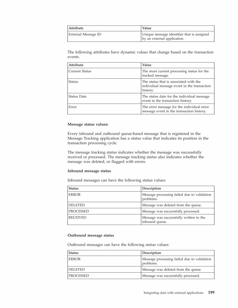
Attribute Value
External Message ID Unique message identifier that is assignedby an external application.
The following attributes have dynamic values that change based on the transactionevents.
Attribute Value
Current Status The most current processing status for thetracked message.
Status The status that is associated with theindividual message event in the transactionhistory.
Status Date The status date for the individual messageevent in the transaction history.
Error The error message for the individual errormessage event in the transaction history.
Message status values:
Every inbound and outbound queue-based message that is registered in theMessage Tracking application has a status value that indicates its position in thetransaction processing cycle.
The message tracking status indicates whether the message was successfullyreceived or processed. The message tracking status also indicates whether themessage was deleted, or flagged with errors.
Inbound message status
Inbound messages can have the following status values:
Status Description
ERROR Message processing failed due to validationproblems.
DELETED Message was deleted from the queue.
PROCESSED Message was successfully processed.
RECEIVED Message was successfully written to theinbound queue.
Outbound message status
Outbound messages can have the following status values:
Status Description
ERROR Message processing failed due to validationproblems.
DELETED Message was deleted from the queue.
PROCESSED Message was successfully processed.
Integrating data with external applications 199
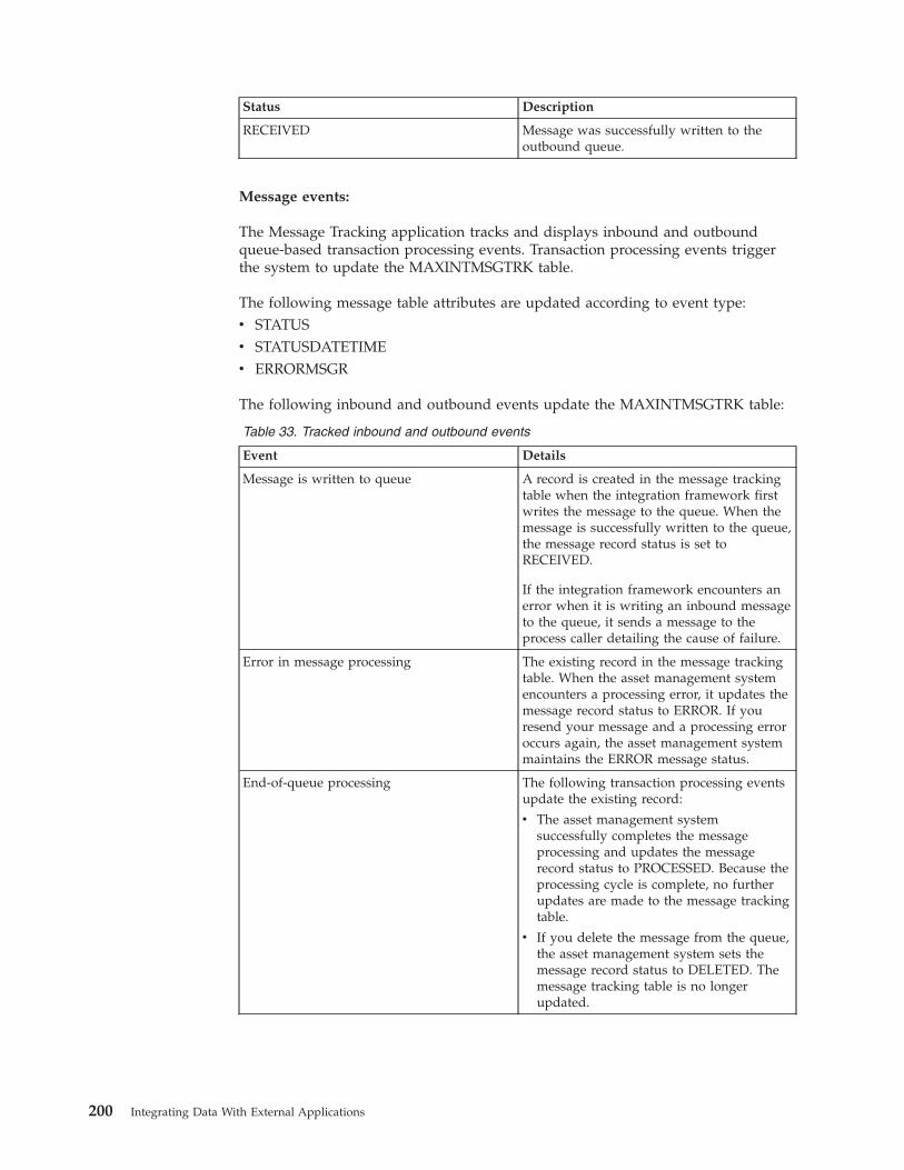
Status Description
RECEIVED Message was successfully written to theoutbound queue.
Message events:
The Message Tracking application tracks and displays inbound and outboundqueue-based transaction processing events. Transaction processing events triggerthe system to update the MAXINTMSGTRK table.
The following message table attributes are updated according to event type:v STATUSv STATUSDATETIMEv ERRORMSGR
The following inbound and outbound events update the MAXINTMSGTRK table:
Table 33. Tracked inbound and outbound events
Event Details
Message is written to queue A record is created in the message trackingtable when the integration framework firstwrites the message to the queue. When themessage is successfully written to the queue,the message record status is set toRECEIVED.
If the integration framework encounters anerror when it is writing an inbound messageto the queue, it sends a message to theprocess caller detailing the cause of failure.
Error in message processing The existing record in the message trackingtable. When the asset management systemencounters a processing error, it updates themessage record status to ERROR. If youresend your message and a processing erroroccurs again, the asset management systemmaintains the ERROR message status.
End-of-queue processing The following transaction processing eventsupdate the existing record:
v The asset management systemsuccessfully completes the messageprocessing and updates the messagerecord status to PROCESSED. Because theprocessing cycle is complete, no furtherupdates are made to the message trackingtable.
v If you delete the message from the queue,the asset management system sets themessage record status to DELETED. Themessage tracking table is no longerupdated.
200 Integrating Data With External Applications
Message tracking configuration:
You can track messages that are sent through publish channels or that are receivedfrom enterprise services.
In the Publish Channels and Enterprise Services applications, you can configurethe following message tracking functions:v Enable or disable message tracking.v Store transaction messages in the database along with the tracking details.v Specify the message data that the Message Tracking application search function
uses by using an XPATH expression.v Uniquely identify messages with a single ID value by using an XPATH
expression.v Identify messages with a search ID value by using an XPATH expression.
The XPATH expressions that are associated with the external message ID valuesand the search ID values can identify multiple nodes in an XML file. In this case,the message ID and search ID values are registered as a comma-separated list ofvalues. Database field lengths are applicable to external ID and search ID fields. Ifnecessary, you can adjust the length of these fields in the Database Configurationapplication.
Stored messages
When you configure message tracking, messages and message tracking details aresaved in the database and can be viewed in the Message Reprocessing application.
External message tracking ID
Each inbound message has an external message identifier that is stored in theMAXINTMSGTRK table. With the Message Tracking application, you can use thisexternal message ID to locate specific messages. The syntax that you use to identifya message node must be a fully qualified XPATH expression.
To find all messages for the MXPERSONInterface enterprise service, specify thefollowing fully qualified XPATH expression in the External Message ID field:/{http://www.ibm.com/maximo}SyncMXPERSON/@messageID
When a multi-noun inbound message is received, the integration framework usesthe XPATH expression for the external message ID to identify the message. If theXPATH expression points to an element included in each one of the nouns in theinbound message, the integration framework creates a multi-noun,comma-separated list of external identifiers.
Search ID
By specifying an XPATH expression to identify nodes, the integration frameworkcan perform efficient multi-noun searches. The system stores the search identifierin the MAXINTMSGTRK table.
To find all messages for the MXPERSONInterface enterprise service, create thefollowing fully qualified XPATH expression as the search ID:
Integrating data with external applications 201
/{http://www.ibm.com/maximo}SyncMXPERSON/{http://www.ibm.com/maximo}MXPERSONSet/{http://www.ibm.com/maximo}PERSON/{http://www.ibm.com/maximo}PERSONID
When a multi-noun inbound message is received, the integration framework usesthe XPATH expression for the search ID to identify the message. If the XPATHexpression points to an element included in each one of the nouns in the inboundmessage, the integration framework creates a multi-noun, comma-separated list ofsearch identifiers.
Enabling message tracking:
Enable message tracking for outbound transactions in the Publish Channelsapplication and for inbound transactions in the Enterprise Services application.
Procedure
1. In the Publish Channels application or the Enterprise Services application,select the channel or service that processes integration messages.
2. Select the Message Tracking action.3. In the Message Tracking Setting window, select the Enable Message Tracking
check box.4. Optional: Select the Store Message check box to store transaction messages.5. Optional: In the External Message ID field, specify one or more XPATH
expressions to locate specific messages.6. Optional: In the Search ID field, specify one or more XPATH expressions to
search for messages.
Cluster configurationThe integration framework can provide integration services across a cluster ofapplication servers. If the continuous queue on a single server is inadequate foryour message volume, you can add central processing units, hardware, and acluster configuration to improve message processing performance.
When you implement a server cluster, you can use multiple servers simultaneouslyto process inbound messages. These messages are processed in the continuousqueues by using message-driven beans (MDBs). Cluster configurations facilitate theprocessing of messages in large volumes.
JMS queues in a server clusterIn a cluster configuration, JMS queues are associated with one member of theserver cluster and access to the queues is provided by the Java Naming andDirectory Interface (JNDI) service.
The JDNI service is available across all the members on the cluster.
202 Integrating Data With External Applications
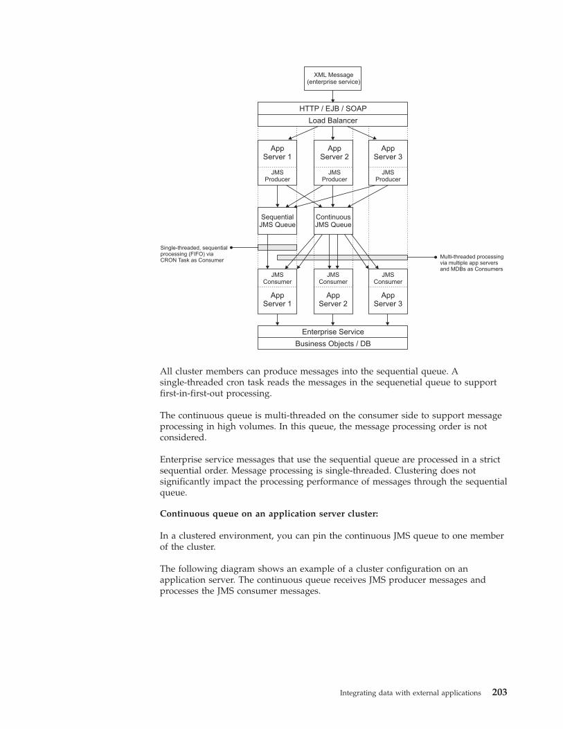
XML Message(enterprise service)
HTTP / EJB / SOAP
Load Balancer
AppServer 1
JMSProducer
AppServer 2
JMSProducer
AppServer 3
JMSProducer
ContinuousJMS Queue
AppServer 1
JMSConsumer
AppServer 2
JMSConsumer
AppServer 3
JMSConsumer
Enterprise Service
Business Objects / DB
Multi-threaded processingvia multiple app serversand MDBs as Consumers
Single-threaded, sequentialprocessing (FIFO) viaCRON Task as Consumer
SequentialJMS Queue
All cluster members can produce messages into the sequential queue. Asingle-threaded cron task reads the messages in the sequenetial queue to supportfirst-in-first-out processing.
The continuous queue is multi-threaded on the consumer side to support messageprocessing in high volumes. In this queue, the message processing order is notconsidered.
Enterprise service messages that use the sequential queue are processed in a strictsequential order. Message processing is single-threaded. Clustering does notsignificantly impact the processing performance of messages through the sequentialqueue.
Continuous queue on an application server cluster:
In a clustered environment, you can pin the continuous JMS queue to one memberof the cluster.
The following diagram shows an example of a cluster configuration on anapplication server. The continuous queue receives JMS producer messages andprocesses the JMS consumer messages.
Integrating data with external applications 203
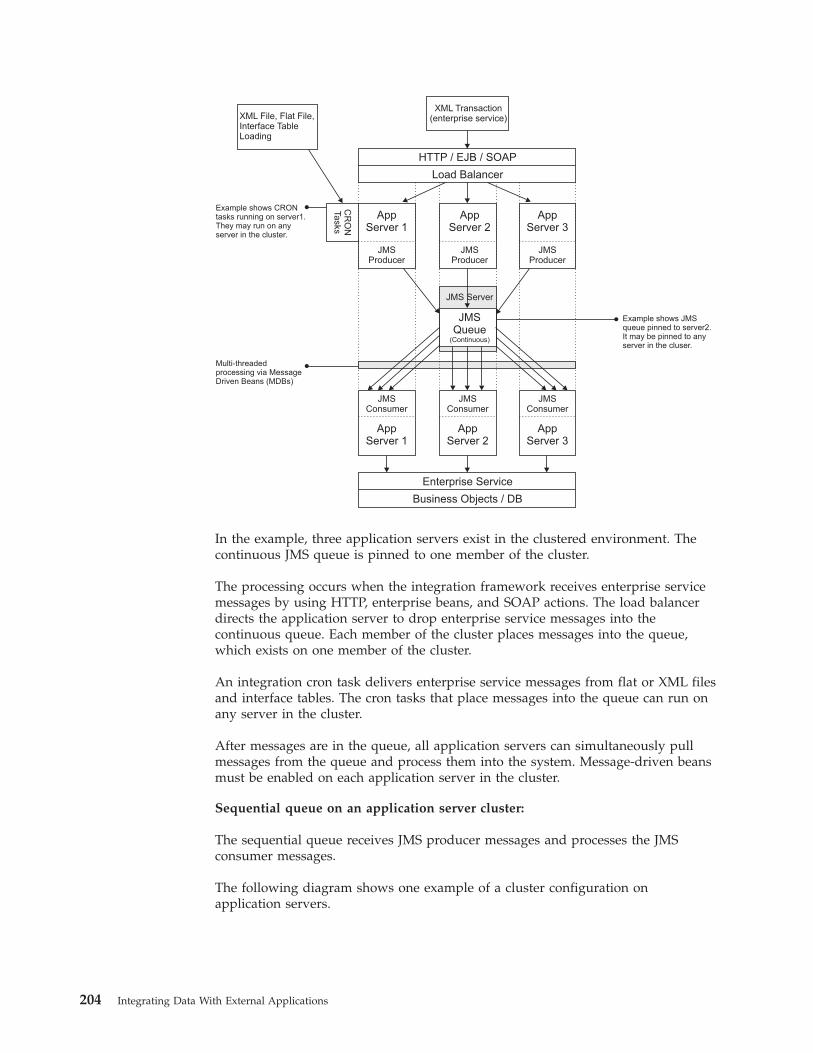
XML File, Flat File,Interface TableLoading
XML Transaction(enterprise service)
HTTP / EJB / SOAP
Load Balancer
AppServer 1
JMSProducer
CR
ON
Ta
sks
AppServer 2
JMSProducer
AppServer 3
JMSProducer
JMSQueue
(Continuous)
JMS Server
AppServer 1
JMSConsumer
AppServer 2
JMSConsumer
AppServer 3
JMSConsumer
Enterprise Service
Business Objects / DB
Example shows JMSqueue pinned to server2.It may be pinned to anyserver in the cluser.
Multi-threadedprocessing via MessageDriven Beans (MDBs)
Example shows CRONtasks running on server1.They may run on anyserver in the cluster.
In the example, three application servers exist in the clustered environment. Thecontinuous JMS queue is pinned to one member of the cluster.
The processing occurs when the integration framework receives enterprise servicemessages by using HTTP, enterprise beans, and SOAP actions. The load balancerdirects the application server to drop enterprise service messages into thecontinuous queue. Each member of the cluster places messages into the queue,which exists on one member of the cluster.
An integration cron task delivers enterprise service messages from flat or XML filesand interface tables. The cron tasks that place messages into the queue can run onany server in the cluster.
After messages are in the queue, all application servers can simultaneously pullmessages from the queue and process them into the system. Message-driven beansmust be enabled on each application server in the cluster.
Sequential queue on an application server cluster:
The sequential queue receives JMS producer messages and processes the JMSconsumer messages.
The following diagram shows one example of a cluster configuration onapplication servers.
204 Integrating Data With External Applications
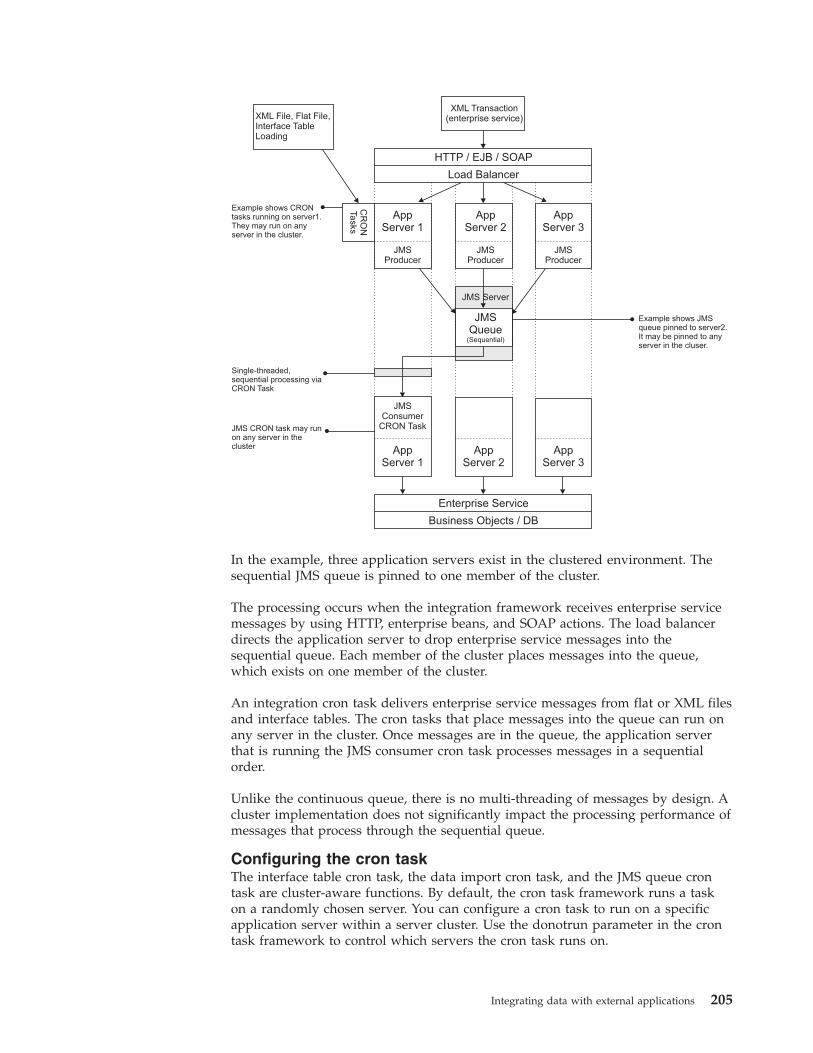
XML File, Flat File,Interface TableLoading
XML Transaction(enterprise service)
HTTP / EJB / SOAP
Load Balancer
AppServer 1
JMSProducer
CR
ON
Ta
sks
AppServer 2
JMSProducer
AppServer 3
JMSProducer
JMSQueue
(Sequential)
JMS Server
JMS CRON task may runon any server in thecluster App
Server 1
JMSConsumer
CRON Task
AppServer 2
AppServer 3
Enterprise Service
Business Objects / DB
Example shows JMSqueue pinned to server2.It may be pinned to anyserver in the cluser.
Single-threaded,sequential processing viaCRON Task
Example shows CRONtasks running on server1.They may run on anyserver in the cluster.
In the example, three application servers exist in the clustered environment. Thesequential JMS queue is pinned to one member of the cluster.
The processing occurs when the integration framework receives enterprise servicemessages by using HTTP, enterprise beans, and SOAP actions. The load balancerdirects the application server to drop enterprise service messages into thesequential queue. Each member of the cluster places messages into the queue,which exists on one member of the cluster.
An integration cron task delivers enterprise service messages from flat or XML filesand interface tables. The cron tasks that place messages into the queue can run onany server in the cluster. Once messages are in the queue, the application serverthat is running the JMS consumer cron task processes messages in a sequentialorder.
Unlike the continuous queue, there is no multi-threading of messages by design. Acluster implementation does not significantly impact the processing performance ofmessages that process through the sequential queue.
Configuring the cron taskThe interface table cron task, the data import cron task, and the JMS queue crontask are cluster-aware functions. By default, the cron task framework runs a taskon a randomly chosen server. You can configure a cron task to run on a specificapplication server within a server cluster. Use the donotrun parameter in the crontask framework to control which servers the cron task runs on.
Integrating data with external applications 205
Configuring a message processing serverFor high volumes of inbound messages, you can improve server efficiency bymoving inbound message processing to a separate application server or servercluster.
Procedure1. Deploy a separate application EAR file on the message processing server or
server cluster.2. On the message processing application server or server cluster, use the
donotrun parameter in the cron task framework to control which servers thecron task runs on.
3. Optional: Configure message-driven beans to pull data from the inboundcontinuous queue. Do not enable message-driven beans for inbound processingwithin the server or server cluster that is dedicated for online users. You canrun other background processing cron tasks on this server or server cluster.
4. Optional: Grant user interface access to users who use of the data importfeature.
Global directory configurationIn a cluster environment, if you configure a global directory for management ofintegration files, the directory must be accessible to all members of the cluster.
Depending upon your use of the integration framework components, files may ormay not be written to the global directory. One of the main reasons for configuringa global directory is to support the use of file-based endpoints. If you intend to usefile-based endpoints for invocation channels and messages are initiated byapplication users that are configured in a UI cluster, all members of the clustermust have visibility to the global directory.
To define the global directory, update the mxe.int.globaldir system property inthe System Properties application.
Access to services by inbound messagesEnterprise services, object structure services, and standard services can all functionin a server cluster.
An inbound transaction can access the relevant service with any of the followingcommunication methods:v Java remote method invocation (RMI), Internet Inter-ORB Protocol (IIOP), and
enterprise beansv HTTP and HTTPS servletv SOAP, HTTP, and HTTPS servlet
Enterprise beans
With a single server, the provider URL for accessing the JNDI tree is the singleserver URL. With a server cluster, the provider URL can be the URL of any of theservers that has the enterprise beans deployed. All members of the cluster sharethe JNDI tree and any member of the cluster can look for and retrieve a cluster.
Following a cluster look up, the client retrieves a cluster-aware proxy of theenterprise beans which load balances all the subsequent calls that use that proxy.Load balancing happens transparently to the client code. There is no differencebetween the code for a single server and for a cluster setup. A separate enterprise
206 Integrating Data With External Applications
bean is deployed for each type of service: object structure service, enterpriseservice, and standard service.
HTTP servlet
The integration servlet is deployed across all members of the cluster. With a singleserver configuration, the URL is the HTTP and HTTPS URL of that server. With acluster server configuration, the URL is the HTTP and HTTPS URL of the loadbalancer for the cluster. A separate servlet is deployed for each type of service:object structure, enterprise, and standard service.
The URL formats for each service are shown in the following table. The meawebvariable in the URL represents the value you specify for the mxe.int.webappurl inthe System Properties application.
Service URL
Object structure service http://hostname:port/meaweb/os/object structurename
Enterprise service (bypassingqueue)
http://hostname:port/meaweb/es/extsysname/enterprise service name
Enterprise service (through thequeue)
http://hostname:port/meaweb/esqueue/extsysname/enterprise service name
Standard service http://hostname:port/meaweb/ss/standard servicename
Web services
Integration web services are homogeneously deployed across all the servermembers in the cluster. Web service access for a cluster is the same as for a singleserver, except that the web service URL and Web Service Definition Language(WSDL) URL point to the cluster instead of to a specific server in the cluster.
The following properties must point to the cluster URL:v Web application URL mxe.int.webappurl
v UDDI registry inquiry URL mxe.int.uddiinurl
v UDDI registry publish URL mxe.int.uddipuburl
The URL to access a web service is http://hostname:port/meaweb/services/webservice name. The meaweb variable in the URL represents the value you specify forthe mxe.int.webappurl in the System Properties application.
Integration securityThe integration framework includes support for J2EE authentication and forcomponent-level authorization.
Authentication securityYou can configure J2EE authentication security for JMS queues, EJB, HTTP, andweb services. You can also configure authentication security for remote integrationAPIs and for the Java handler classes for outbound routing.
Integrating data with external applications 207
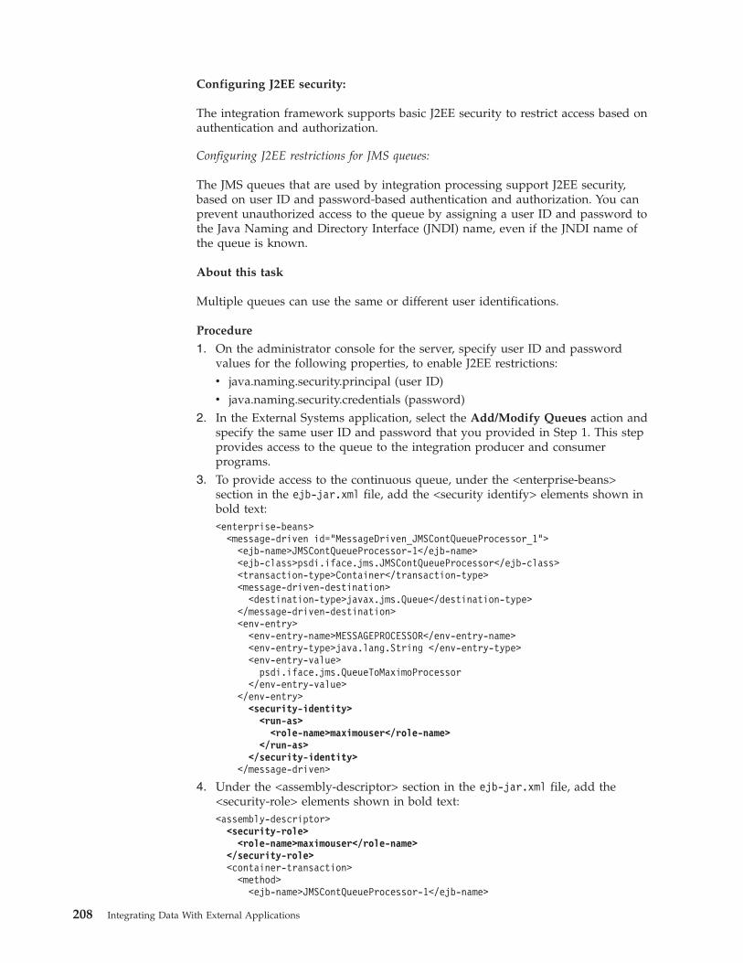
Configuring J2EE security:
The integration framework supports basic J2EE security to restrict access based onauthentication and authorization.
Configuring J2EE restrictions for JMS queues:
The JMS queues that are used by integration processing support J2EE security,based on user ID and password-based authentication and authorization. You canprevent unauthorized access to the queue by assigning a user ID and password tothe Java Naming and Directory Interface (JNDI) name, even if the JNDI name ofthe queue is known.
About this task
Multiple queues can use the same or different user identifications.
Procedure
1. On the administrator console for the server, specify user ID and passwordvalues for the following properties, to enable J2EE restrictions:v java.naming.security.principal (user ID)v java.naming.security.credentials (password)
2. In the External Systems application, select the Add/Modify Queues action andspecify the same user ID and password that you provided in Step 1. This stepprovides access to the queue to the integration producer and consumerprograms.
3. To provide access to the continuous queue, under the <enterprise-beans>section in the ejb-jar.xml file, add the <security identify> elements shown inbold text:<enterprise-beans>
<message-driven id="MessageDriven_JMSContQueueProcessor_1"><ejb-name>JMSContQueueProcessor-1</ejb-name><ejb-class>psdi.iface.jms.JMSContQueueProcessor</ejb-class><transaction-type>Container</transaction-type><message-driven-destination>
<destination-type>javax.jms.Queue</destination-type></message-driven-destination><env-entry>
<env-entry-name>MESSAGEPROCESSOR</env-entry-name><env-entry-type>java.lang.String </env-entry-type><env-entry-value>
psdi.iface.jms.QueueToMaximoProcessor</env-entry-value>
</env-entry><security-identity>
<run-as><role-name>maximouser</role-name>
</run-as></security-identity>
</message-driven>
4. Under the <assembly-descriptor> section in the ejb-jar.xml file, add the<security-role> elements shown in bold text:<assembly-descriptor>
<security-role><role-name>maximouser</role-name>
</security-role><container-transaction>
<method><ejb-name>JMSContQueueProcessor-1</ejb-name>
208 Integrating Data With External Applications
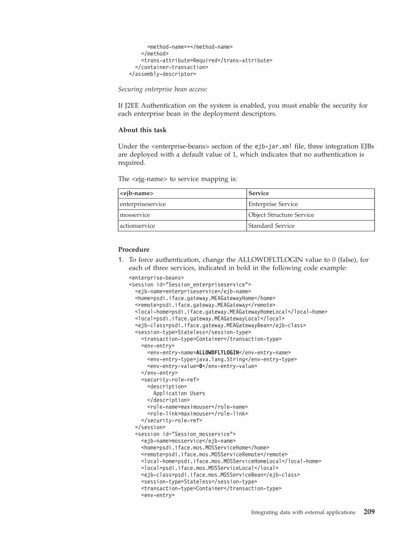
<method-name>*</method-name></method><trans-attribute>Required</trans-attribute>
</container-transaction></assembly-descriptor>
Securing enterprise bean access:
If J2EE Authentication on the system is enabled, you must enable the security foreach enterprise bean in the deployment descriptors.
About this task
Under the <enterprise-beans> section of the ejb-jar.xml file, three integration EJBsare deployed with a default value of 1, which indicates that no authentication isrequired.
The <ejg-name> to service mapping is:
<ejb-name> Service
enterpriseservice Enterprise Service
mosservice Object Structure Service
actionservice Standard Service
Procedure
1. To force authentication, change the ALLOWDFLTLOGIN value to 0 (false), foreach of three services, indicated in bold in the following code example:<enterprise-beans><session id="Session_enterpriseservice">
<ejb-name>enterpriseservice</ejb-name><home>psdi.iface.gateway.MEAGatewayHome</home><remote>psdi.iface.gateway.MEAGateway</remote><local-home>psdi.iface.gateway.MEAGatewayHomeLocal</local-home><local>psdi.iface.gateway.MEAGatewayLocal</local><ejb-class>psdi.iface.gateway.MEAGatewayBean</ejb-class><session-type>Stateless</session-type>
<transaction-type>Container</transaction-type><env-entry>
<env-entry-name>ALLOWDFLTLOGIN</env-entry-name><env-entry-type>java.lang.String</env-entry-type><env-entry-value>0</env-entry-value>
</env-entry><security-role-ref>
<description>Application Users
</description><role-name>maximouser</role-name><role-link>maximouser</role-link>
</security-role-ref></session><session id="Session_mosservice">
<ejb-name>mosservice</ejb-name><home>psdi.iface.mos.MOSServiceHome</home><remote>psdi.iface.mos.MOSServiceRemote</remote><local-home>psdi.iface.mos.MOSServiceHomeLocal</local-home><local>psdi.iface.mos.MOSServiceLocal</local><ejb-class>psdi.iface.mos.MOSServiceBean</ejb-class><session-type>Stateless</session-type><transaction-type>Container</transaction-type><env-entry>
Integrating data with external applications 209
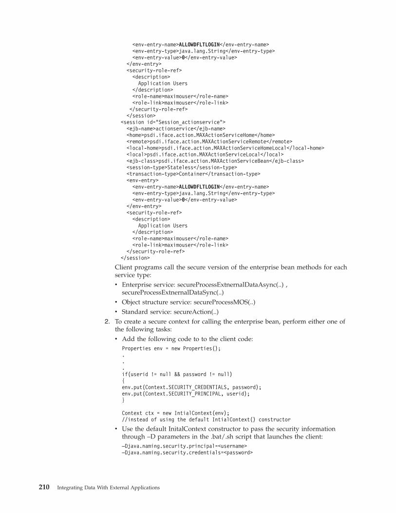
<env-entry-name>ALLOWDFLTLOGIN</env-entry-name><env-entry-type>java.lang.String</env-entry-type><env-entry-value>0</env-entry-value>
</env-entry><security-role-ref>
<description>Application Users
</description><role-name>maximouser</role-name><role-link>maximouser</role-link></security-role-ref></session>
<session id="Session_actionservice"><ejb-name>actionservice</ejb-name><home>psdi.iface.action.MAXActionServiceHome</home><remote>psdi.iface.action.MAXActionServiceRemote</remote><local-home>psdi.iface.action.MAXActionServiceHomeLocal</local-home><local>psdi.iface.action.MAXActionServiceLocal</local><ejb-class>psdi.iface.action.MAXActionServiceBean</ejb-class><session-type>Stateless</session-type><transaction-type>Container</transaction-type><env-entry>
<env-entry-name>ALLOWDFLTLOGIN</env-entry-name><env-entry-type>java.lang.String</env-entry-type><env-entry-value>0</env-entry-value>
</env-entry><security-role-ref>
<description>Application Users
</description><role-name>maximouser</role-name><role-link>maximouser</role-link>
</security-role-ref></session>
Client programs call the secure version of the enterprise bean methods for eachservice type:v Enterprise service: secureProcessExtnernalDataAsync(..) ,
secureProcessExtnernalDataSync(..)v Object structure service: secureProcessMOS(..)v Standard service: secureAction(..)
2. To create a secure context for calling the enterprise bean, perform either one ofthe following tasks:v Add the following code to to the client code:
Properties env = new Properties();...if(userid != null && password != null){env.put(Context.SECURITY_CREDENTIALS, password);env.put(Context.SECURITY_PRINCIPAL, userid);}
Context ctx = new IntialContext(env);//instead of using the default IntialContext() constructor
v Use the default InitalContext constructor to pass the security informationthrough –D parameters in the .bat/.sh script that launches the client:–Djava.naming.security.principal=<username>–Djava.naming.security.credentials=<password>
210 Integrating Data With External Applications
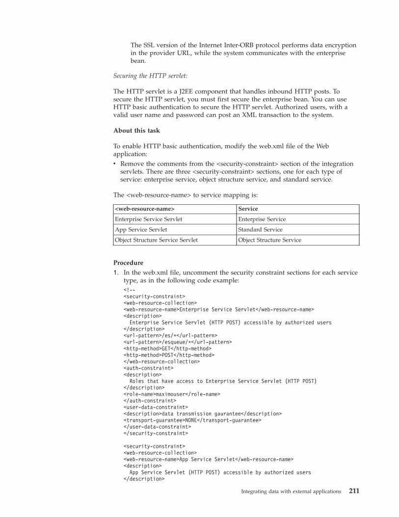
The SSL version of the Internet Inter-ORB protocol performs data encryptionin the provider URL, while the system communicates with the enterprisebean.
Securing the HTTP servlet:
The HTTP servlet is a J2EE component that handles inbound HTTP posts. Tosecure the HTTP servlet, you must first secure the enterprise bean. You can useHTTP basic authentication to secure the HTTP servlet. Authorized users, with avalid user name and password can post an XML transaction to the system.
About this task
To enable HTTP basic authentication, modify the web.xml file of the Webapplication:v Remove the comments from the <security-constraint> section of the integration
servlets. There are three <security-constraint> sections, one for each type ofservice: enterprise service, object structure service, and standard service.
The <web-resource-name> to service mapping is:
<web-resource-name> Service
Enterprise Service Servlet Enterprise Service
App Service Servlet Standard Service
Object Structure Service Servlet Object Structure Service
Procedure
1. In the web.xml file, uncomment the security constraint sections for each servicetype, as in the following code example:<!--<security-constraint><web-resource-collection><web-resource-name>Enterprise Service Servlet</web-resource-name><description>
Enterprise Service Servlet (HTTP POST) accessible by authorized users</description><url-pattern>/es/*</url-pattern><url-pattern>/esqueue/*</url-pattern><http-method>GET</http-method><http-method>POST</http-method></web-resource-collection><auth-constraint><description>
Roles that have access to Enterprise Service Servlet (HTTP POST)</description><role-name>maximouser</role-name></auth-constraint><user-data-constraint><description>data transmission gaurantee</description><transport-guarantee>NONE</transport-guarantee></user-data-constraint></security-constraint>
<security-constraint><web-resource-collection><web-resource-name>App Service Servlet</web-resource-name><description>
App Service Servlet (HTTP POST) accessible by authorized users</description>
Integrating data with external applications 211
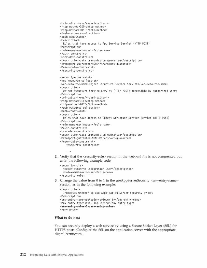
<url-pattern>/ss/*</url-pattern><http-method>GET</http-method><http-method>POST</http-method></web-resource-collection><auth-constraint><description>
Roles that have access to App Service Servlet (HTTP POST)</description><role-name>maximouser</role-name></auth-constraint><user-data-constraint><description>data transmission gaurantee</description><transport-guarantee>NONE</transport-guarantee></user-data-constraint></security-constraint>
<security-constraint><web-resource-collection><web-resource-name>Object Structure Service Servlet</web-resource-name><description>
Object Structure Service Servlet (HTTP POST) accessible by authorized users</description><url-pattern>/os/*</url-pattern><http-method>GET</http-method><http-method>POST</http-method></web-resource-collection><auth-constraint><description>
Roles that have access to Object Structure Service Servlet (HTTP POST)</description><role-name>maximouser</role-name></auth-constraint><user-data-constraint><description>data transmission gaurantee</description><transport-guarantee>NONE</transport-guarantee></user-data-constraint>
</security-constraint>
-->
2. Verify that the <security-role> section in the web.xml file is not commented out,as in the following example code:<security-role>
<description>An Integration User</description><role-name>maximouser</role-name>
</security-role>
3. Change the value from 0 to 1 in the useAppServerSecurity <env-entry-name>section, as in the following example:<description>
Indicates whether to use Application Server security or not</description><env-entry-name>useAppServerSecurity</env-entry-name><env-entry-type>java.lang.String</env-entry-type><env-entry-value>1</env-entry-value></env-entry>
What to do next
You can securely deploy a web service by using a Secure Socket Layer (SSL) forHTTPS posts. Configure the SSL on the application server with the appropriatedigital certificates.
212 Integrating Data With External Applications
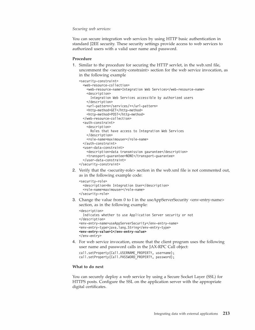
Securing web services:
You can secure integration web services by using HTTP basic authentication instandard J2EE security. These security settings provide access to web services toauthorized users with a valid user name and password.
Procedure
1. Similar to the procedure for securing the HTTP servlet, in the web.xml file,uncomment the <security-constraint> section for the web service invocation, asin the following example<security-constraint>
<web-resource-collection><web-resource-name>Integration Web Services</web-resource-name><description>
Integration Web Services accessible by authorized users</description><url-pattern>/services/*</url-pattern><http-method>GET</http-method><http-method>POST</http-method>
</web-resource-collection><auth-constraint>
<description>Roles that have access to Integration Web Services
</description><role-name>maximouser</role-name>
</auth-constraint><user-data-constraint>
<description>data transmission gaurantee</description><transport-guarantee>NONE</transport-guarantee>
</user-data-constraint></security-constraint>
2. Verify that the <security-role> section in the web.xml file is not commented out,as in the following example code:<security-role>
<description>An Integration User</description><role-name>maximouser</role-name>
</security-role>
3. Change the value from 0 to I in the useAppServerSecurity <env-entry-name>section, as in the following example:<description>
Indicates whether to use Application Server security or not</description><env-entry-name>useAppServerSecurity</env-entry-name><env-entry-type>java.lang.String</env-entry-type><env-entry-value>1</env-entry-value></env-entry>
4. For web service invocation, ensure that the client program uses the followinguser name and password calls in the JAX-RPC Call object:call.setProperty(Call.USERNAME_PROPERTY, username);call.setProperty(Call.PASSWORD_PROPERTY, password);
What to do next
You can securely deploy a web service by using a Secure Socket Layer (SSL) forHTTPS posts. Configure the SSL on the application server with the appropriatedigital certificates.
Integrating data with external applications 213
Interface table security:
Interface tables use the default database authentication and authorization. Ifauthentication and authorization are in effect, external programs that read or writeto the interface tables must provide proper authorization. To read from and writeto the interface tables, the USERNAME and PASSWORD values are configured forthe endpoint that implements the interface table handler.
Securing remote integration APIs:
Some MicService remote APIs secure access by forcing the user of those methodsto provide the UserInfo object. If a valid UserInfo object is not provided, an erroroccurs and the call is not completed.
The following remote methods are protected because they either provide sensitiveinformation or perform sensitive data transaction processing:v exportData(..)v deleteQueueData(..)v processExternalData(..) (both versions)v query(..)v viewQueueData(..)v loadData(..)v loadSystemData(..)v processObjectStructure(..)v routeData(..)
To run these methods, the caller must retrieve a valid UserInfo object and pass it tothe method to gain access to the secure layer.
A UserInfo object is a serialized object that contains user details including user,password, locale, language, and time zone information, that is used for securitypurposes.
The system uses Java Remote Method Invocation (RMI) and Java Remote MethodProtocol (JRMP). You can communicate to the system services by using a secureversion of JRMP protocol using SSL.
Outbound router handler security:
The outbound router handlers have support for authorization and confidentiality.The enterprise bean, HTTP, JMS, web service, and interface table handlers havesupport for security.
Authorization securityYou can configure authorization security at application-level, object-level, or at thelevel of a method defined in a standard service. After user authenticationcompletes, the integration framework checks that the user has been granted theauthority to send messages to the target application, object, or method.
Object-level authorization
Object-level authorization is based on the security configuration set in the DataRestrictions tab of the Security Groups application. If an object or attribute ismarked as read-only or hidden, inbound message data processing is limited to
214 Integrating Data With External Applications
queries. You cannot insert, update, or delete data in the relevant object or attribute.
Application-level authorization
You configure application-level authorization in the Object Structures application.In the Authorized Application field, specify the application to authorize. Thespecified application and the user group of the integration message user togetherprovide authorization for inbound integration messages for both object structuresand enterprise services. The combination of application and user group alsoprovide authorization for the export of data related to this object structure.
If you use the REST API, you might need to configure application-levelauthorization to access business object resources.
Standard service authorization
Standard service authorization does not support the use of a condition that youassociate with the signature option. Any condition that you assign is ignored.
You can configure a standard service transaction to take on the same securityprofile for the integration user as if that user entered the transaction through anapplication. This level of authorization requires manual configuration. Theapplication service must have a properly annotated method and the service mustbe registered in the Database Configuration application. Assign a signature optionto a standard service to limit access to the users or groups that are authorized forthe selected option.
Run a SQL script that updates the MAXSERVSECURITY table with the details ofthe standard service to authorize. The insert statement for theMAXSERVSECURITY must include the fields listed in the following table.
Field Description
MAXSERVSECURITYID A unique ID that is numeric. You can, forexample, query themax(MAXSERVSECURITYID) fromMAXSERVSECURITY and use the nextsequential value.
ROWSTAMP A unique ID that is numeric. You can, forexample, query the max(ROWSTAMP) fromMAXSERVSECURITY and use the nextsequential value.
SERVICENAME The service name registered in the DatabaseConfiguration application(MAXSERVICE.SERVICENAME).
APP The application name where the signatureoption is configured to (MAXAPPS.APP).
METHODNAME The name of the annotated method in theapplication service.
OPTIONNAME This value is a combination of the signatureoption table for the application and thesignature option(SIGOPTION.OPTIONNAME).
Related concepts:
Integrating data with external applications 215
“REST API” on page 226The Representational State Transfer (REST) application programming interface(API) provides a way for external applications to query and update applicationdata in Tivoli's process automation engine.
Language supportYour database can contain some elements, such as descriptions and longdescriptions, in multiple languages. Publish channels and enterprise services caninclude these translated columns. The integration framework also supports the useof bidirectional language formats.
A single database can contain data in multiple languages. You specify the baselanguage when you install the application. If your system uses a language thatdiffers from the base language, you can enable the integration framework to sendand receive data that is not in the base language data.
Default processing of multiple languagesWhen you log in, you can choose a language code other than the base language forthe system. In any application, you can then enter language-specific values forcolumns that are designated as translatable.
By default, outbound transactions contain the applicable column values in thelanguage that is associated with the login session. The language values displaywhether the transaction is initiated by an application or the data export feature.For example, if the base language of your system is English, you can log in as aFrench user and update an item record with a French description. The outboundmessage contains the item description in French, even when the description alsoexists in English, or a third language.
If a database table contains translatable columns, the database contains acorresponding table called L_tablename, for example, ITEM and L_ITEM. TheL_tablename table stores the non-base language values for every translated columnexcept the long description. Long descriptions in all languages are in theLONGDESCRIPTION table.
To include translated values in the output XML, include the L_tablename andLONGDESCRIPTION objects in the applicable object structures. Provide the baselanguage values as a service input to object structures that have the L_tablenameas part of their object definition. Your service input must be in the core object, andall other languages must be in the additional language enabled object.
For example, when English is the base language, the ITEM table contains theEnglish description of an item and the L_ITEM table contains the French andGerman descriptions of that item. The LONGDESCRIPTION table contains theEnglish, French, and German long descriptions.
When you add the L_tablename object to an object structure, assign the same valueto the transLanguage and baseLanguage attributes. Otherwise, the base languagevalues are not available and are processed for the multilanguage-enabled fields.
Multilanguage attributesThe root element of the XML structure for services and channels includes languageattributes that specify the language attributes for the record.
The following language attributes are used:
216 Integrating Data With External Applications
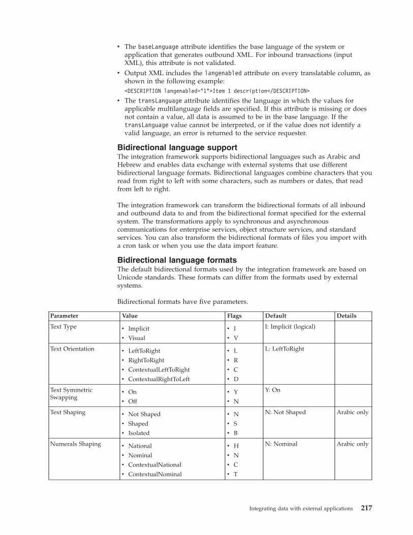
v The baseLanguage attribute identifies the base language of the system orapplication that generates outbound XML. For inbound transactions (inputXML), this attribute is not validated.
v Output XML includes the langenabled attribute on every translatable column, asshown in the following example:<DESCRIPTION langenabled="1">Item 1 description</DESCRIPTION>
v The transLanguage attribute identifies the language in which the values forapplicable multilanguage fields are specified. If this attribute is missing or doesnot contain a value, all data is assumed to be in the base language. If thetransLanguage value cannot be interpreted, or if the value does not identify avalid language, an error is returned to the service requester.
Bidirectional language supportThe integration framework supports bidirectional languages such as Arabic andHebrew and enables data exchange with external systems that use differentbidirectional language formats. Bidirectional languages combine characters that youread from right to left with some characters, such as numbers or dates, that readfrom left to right.
The integration framework can transform the bidirectional formats of all inboundand outbound data to and from the bidirectional format specified for the externalsystem. The transformations apply to synchronous and asynchronouscommunications for enterprise services, object structure services, and standardservices. You can also transform the bidirectional formats of files you import witha cron task or when you use the data import feature.
Bidirectional language formatsThe default bidirectional formats used by the integration framework are based onUnicode standards. These formats can differ from the formats used by externalsystems.
Bidirectional formats have five parameters.
Parameter Value Flags Default Details
Text Type v Implicit
v Visual
v I
v V
I: Implicit (logical)
Text Orientation v LeftToRight
v RightToRight
v ContextualLeftToRight
v ContextualRightToLeft
v L
v R
v C
v D
L: LeftToRight
Text SymmetricSwapping
v On
v Off
v Y
v N
Y: On
Text Shaping v Not Shaped
v Shaped
v Isolated
v N
v S
v B
N: Not Shaped Arabic only
Numerals Shaping v National
v Nominal
v ContextualNational
v ContextualNominal
v H
v N
v C
v T
N: Nominal Arabic only
Integrating data with external applications 217
Configuring bidirectional language support for external systemsSpecify the bidirectional language format used by an external system to enable thecorrect transformation of data to (and from) the default format.
Procedure1. Optional: Select the Bidirectional Format action in the External Systems
application for enterprise services or in the Invocation Channels application forobject structure services.
2. Select the bidirectional language format used by the external system from thelist of options and click OK.
Results
After setting the bidirectional language format used by an external system,transformation to the appropriate format occurs automatically during integrationprocessing.
Exporting and importing file-based dataThe integration administrator can initiate export and import data from within theExternal Systems application to support, for example, integrating data using files.The import process includes the ability to preview a data load from a file tovalidate the data prior to saving it to the database. The import process alsoincludes an option to manage errors that result from file loading in the same fileformat as the imported file
You can use file-based error management as an alternative to managing errorsthrough the Message Reprocessing application. Importing data from files, in flatfile or XML format, can be done on a scheduled basis using a predefined cron task.Additionally, administrators can enable an application for export and import, andusers can then export and import data directly from within the enabledapplication.Related concepts:“Error management with file-based data import” on page 192The integration framework supports error management with the MessageReprocessing application which allows you to review, correct, reprocess, and deletemessages that go in error when processed from an inbound queue. When data isimported from an XML file or a flat file, a second option is available that manageserrors using a downloaded file instead of the Message Reprocessing application.
Exporting and importing data in the External Systemsapplication
You can initiate a data export in the Publish Channels tab of the External Systemsapplication. You can initiate a data import in the Enterprise Services tab of theExternal Systems application.
Exporting file-based dataWith the data export feature, you can perform a bulk export of message data froma file to an external system. You can initiate the export process for each publishchannel that is associated to an external system.
218 Integrating Data With External Applications
Before you begin
In a multitenancy environment, you can use the data export feature only if thesystem provider provides you with access to a file server that is accessible by theapplication server. You must then configure a file-based endpoint to point to thelocation of this file server.
You must enable both the external system and the publish channel before you canexport data. The data for export must either be in an XML file format that adheresto the object structure schema or in a delimited flat file, such as comma separated,that is a flattened version of the object structure schema format.
About this task
The optional SQL query that you enter in the Export Condition field, can affect thesize of the exported XML message. You can filter the content to limit the amount ofdata that is being exported. The export process performs the standard outboundprocessing on the result set of the query for the selected publish channel.
Procedure1. In the External Systems application, click the Publish Channels tab and select
the publish channel that you want to export.2. In the End Point field, specify a file-based endpoint handler, for either XML file
or flat file format.3. Click Data Export.4. Optional: Enter a SQL query in the Export Condition field. The query must be
against the primary or top-level object in the publish channel object structure.5. Optional: Specify an integer value in the Export Count field to limit the
number of records that are contained in the exported file. If the result of thequery contains more records than the number you specify, those records are notincluded in the exported file.
6. Click OK to begin the data export process.
What to do next
When the data export is executed, the selected data is formed into a message anddropped into the outbound queue that is configured for the publish channel andits corresponding external system. The message is then processed from theoutbound queue to the configured endpoint. If an error occurs when delivering amessage to the endpoint, you can manage and view the data export messages thatare flagged with an error in the Message Reprocessing application.
Importing file-based dataYou can use the data import feature to load data from either XML or flat, delimitedfiles, to update the Maximo database. You can preview and validate the data priorto loading it and committing it to the database. You can choose to manage errorswith the Message Reprocessing application or by extracting errors to a file formatthat is the same as the imported file format.
Before you begin
Before data can be imported, if you plan to import data from a flat file, such as a.csv file, the enterprise service object structure must support flat file structures.Ensure that the Support Flat File Structure check box is selected on the associatedobject structure record in the Object Structures application. You also must enable
Integrating data with external applications 219
both the external system and the enterprise service before you can import data.
About this task
The data that you import must be in a delimited flat file, such as commaseparated, or an XML file format. The data import process can use a predefined oruser-defined enterprise service.
Procedure1. In the External Systems application, display the external system that contains
the enterprise service from which you want to import data.2. On the Enterprise Services tab, select the enterprise service from which you
want to import data.3. Click Data Import.4. Optional: Select the Import Preview check box to examine the data before
importing and committing the data to the database. Use the preview option tosample data records. This feature is not intended to support a large filecontaining hundreds of records. Processing synchronously processes the file tothe business objects and returns any error messages encountered, withoutcommitting any updates to the database.
5. Specify the type of file that you want to use for the file import.
Option Description
XML File Imported data is in XML format.
Flat File Imported data is in a delimited flat file. Ifnecessary, modify the Delimiter and TextQualifier values.
6. In the Specify Import File field, enter the file name path the imported file usesfor identification and storage.
7. Select the File-based Error Management check box if you want to manage anyerrors you encounter through a file in the same format as the file beingimported. This option is an alternative to managing errors with the MessageReprocessing application
8. Click OK to begin the import data process.
What to do next
When the data import is executed, the file that is selected for import is formed intomultiple messages and dropped into the inbound queue that is configured for theenterprise service and its corresponding external system. The messages are thenprocessed from the inbound queue to the application objects for updating. Theprocessing of messages from an inbound queue requires the enablement of the JMScron task when the sequential queue is used or the enablement of Message DrivenBeans for the continuous queue. If errors occur when processing a file, you canmanage and view the data import messages that are flagged with an error in theMessage Reprocessing application.
Cron tasks for processing inbound dataIf you want to schedule file loads rather than using the data import window, youmust create, configure, and enable the XMLFILECONSUMER cron task and theFLATFILECONSUMER cron task before cron task message processing can occur.
220 Integrating Data With External Applications
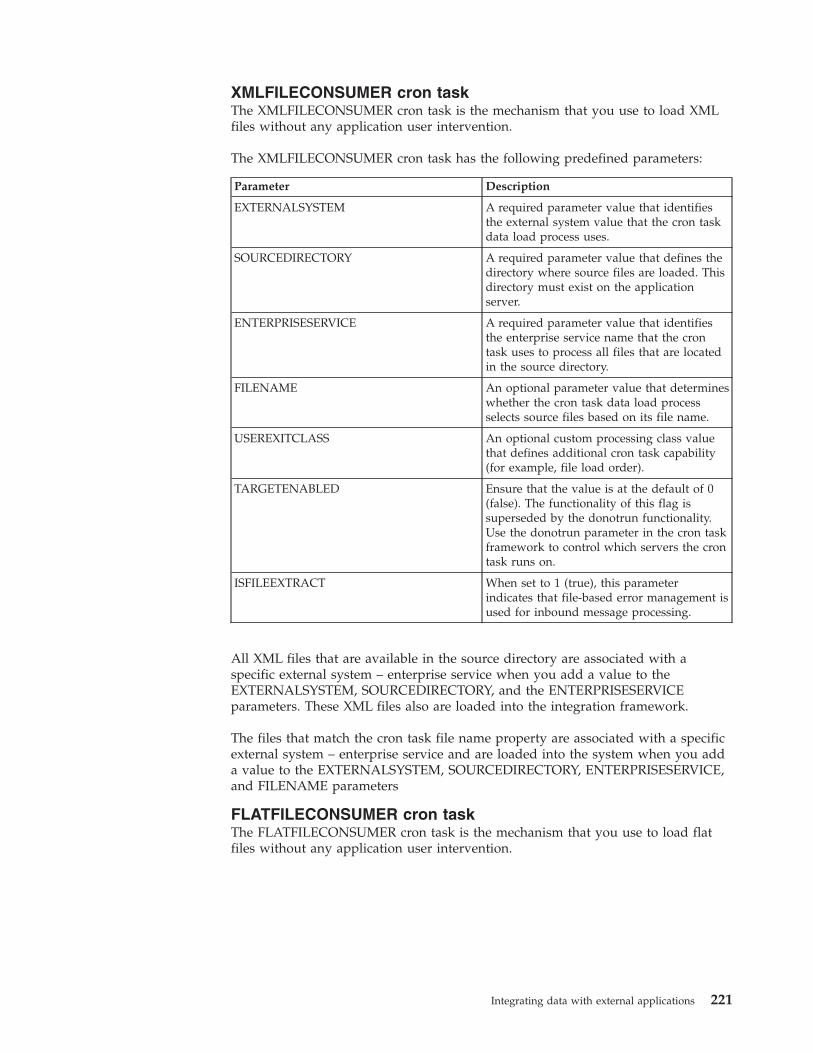
XMLFILECONSUMER cron taskThe XMLFILECONSUMER cron task is the mechanism that you use to load XMLfiles without any application user intervention.
The XMLFILECONSUMER cron task has the following predefined parameters:
Parameter Description
EXTERNALSYSTEM A required parameter value that identifiesthe external system value that the cron taskdata load process uses.
SOURCEDIRECTORY A required parameter value that defines thedirectory where source files are loaded. Thisdirectory must exist on the applicationserver.
ENTERPRISESERVICE A required parameter value that identifiesthe enterprise service name that the crontask uses to process all files that are locatedin the source directory.
FILENAME An optional parameter value that determineswhether the cron task data load processselects source files based on its file name.
USEREXITCLASS An optional custom processing class valuethat defines additional cron task capability(for example, file load order).
TARGETENABLED Ensure that the value is at the default of 0(false). The functionality of this flag issuperseded by the donotrun functionality.Use the donotrun parameter in the cron taskframework to control which servers the crontask runs on.
ISFILEEXTRACT When set to 1 (true), this parameterindicates that file-based error management isused for inbound message processing.
All XML files that are available in the source directory are associated with aspecific external system – enterprise service when you add a value to theEXTERNALSYSTEM, SOURCEDIRECTORY, and the ENTERPRISESERVICEparameters. These XML files also are loaded into the integration framework.
The files that match the cron task file name property are associated with a specificexternal system – enterprise service and are loaded into the system when you adda value to the EXTERNALSYSTEM, SOURCEDIRECTORY, ENTERPRISESERVICE,and FILENAME parameters
FLATFILECONSUMER cron taskThe FLATFILECONSUMER cron task is the mechanism that you use to load flatfiles without any application user intervention.
Integrating data with external applications 221
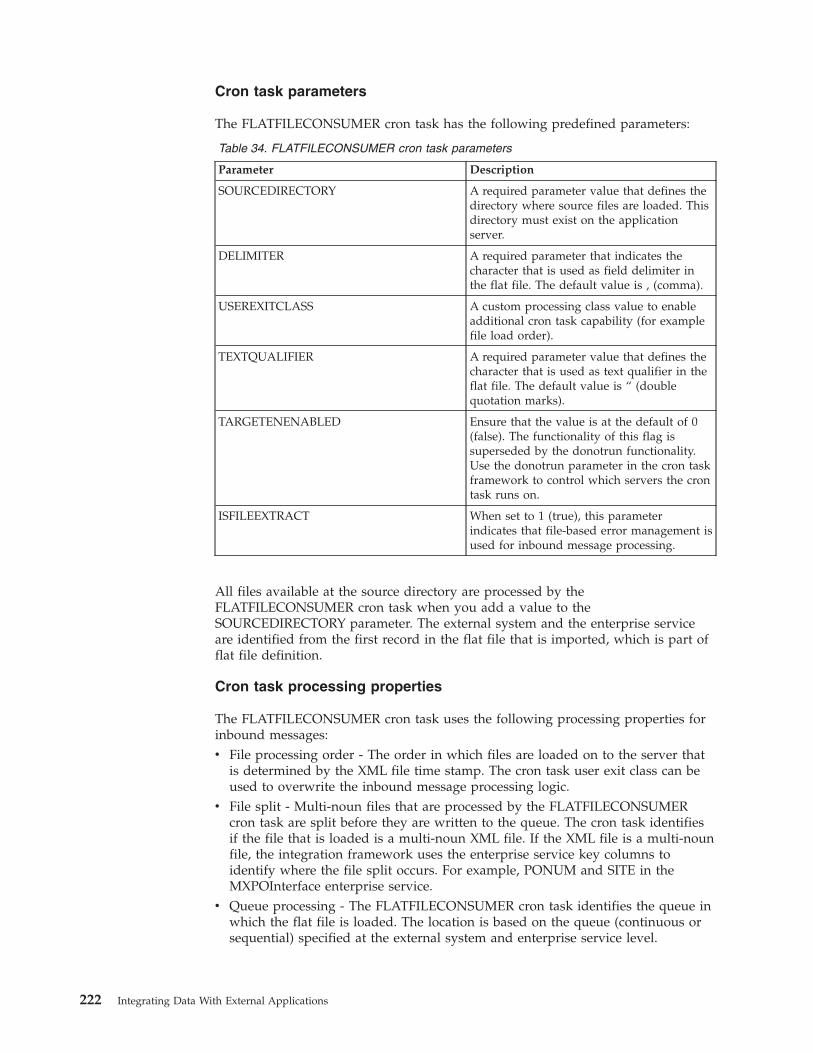
Cron task parameters
The FLATFILECONSUMER cron task has the following predefined parameters:
Table 34. FLATFILECONSUMER cron task parameters
Parameter Description
SOURCEDIRECTORY A required parameter value that defines thedirectory where source files are loaded. Thisdirectory must exist on the applicationserver.
DELIMITER A required parameter that indicates thecharacter that is used as field delimiter inthe flat file. The default value is , (comma).
USEREXITCLASS A custom processing class value to enableadditional cron task capability (for examplefile load order).
TEXTQUALIFIER A required parameter value that defines thecharacter that is used as text qualifier in theflat file. The default value is “ (doublequotation marks).
TARGETENENABLED Ensure that the value is at the default of 0(false). The functionality of this flag issuperseded by the donotrun functionality.Use the donotrun parameter in the cron taskframework to control which servers the crontask runs on.
ISFILEEXTRACT When set to 1 (true), this parameterindicates that file-based error management isused for inbound message processing.
All files available at the source directory are processed by theFLATFILECONSUMER cron task when you add a value to theSOURCEDIRECTORY parameter. The external system and the enterprise serviceare identified from the first record in the flat file that is imported, which is part offlat file definition.
Cron task processing properties
The FLATFILECONSUMER cron task uses the following processing properties forinbound messages:v File processing order - The order in which files are loaded on to the server that
is determined by the XML file time stamp. The cron task user exit class can beused to overwrite the inbound message processing logic.
v File split - Multi-noun files that are processed by the FLATFILECONSUMERcron task are split before they are written to the queue. The cron task identifiesif the file that is loaded is a multi-noun XML file. If the XML file is a multi-nounfile, the integration framework uses the enterprise service key columns toidentify where the file split occurs. For example, PONUM and SITE in theMXPOInterface enterprise service.
v Queue processing - The FLATFILECONSUMER cron task identifies the queue inwhich the flat file is loaded. The location is based on the queue (continuous orsequential) specified at the external system and enterprise service level.
222 Integrating Data With External Applications
The cron task creates an index file (recovery_filename.txt) that contains areference to the last successfully processed noun when you process a multi-nounfile. The entry in the index file is updated when the noun is successfullycommitted to the queue. Index files are available in the RECOVERY folder which iscreated in the cron task source directory.
The FLATFILECONSUMER cron task uses the index file name to identify the filethat was processed before the server or queue problem was encountered. The crontask continues to process the XML file starting at the last successfully committednoun in the index file. Errors that are identified after a message is successfullywritten to an inbound queue must be resolved in the Message Reprocessingapplication.
Configuring an application for data export and importTo enable application-based data import and export you must define the content ofan object structure and enable this object structure for import and export.
Defining the object structure contentApplication users can be granted access to export or import data directly from anapplication. An administrator can identify an appropriate object structure for anapplication and grant either export or import (or both) capabilities for users tomanage application data in a file, such as a .csv file, that can be maintained inspreadsheet.
About this task
Determine the object structure to use for the integration transactions and thenmodify the content of the object structure to limit data exchange to the content thatis required.
Procedure1. In the Application Designer, open the application that you want to enable and
note the value in the Main Object field in the header area. This value must bethe main object that you use for the object structure.
2. In the Object Structures application, specify the name of the main object in theObject Structure field to filter for object structures based on this object. If thesearch does not return any object structures based on the main object, youmust create an object structure and the following steps do not apply.
3. If the search returns multiple object structures, select an object structure wherethe value in the Consumed By field is set to Integration.
4. Review the content of the object structure and ask the following questions:a. Is the main object of the object structure the same as the main object of the
application that you want to enable for data export and import?b. Does the object structure include child objects that contain data that users
do not need to import or export? For example, the MXPERSON objectincludes the PHONE, EMAIL, and SMS child objects. Your users may wantto import and export data for the PERSON and PHONE objects only.
5. After you review the content of the object structure, you can choose to use thepredefined object structure with all of its existing content or to duplicate thisobject structure and modify its content. If you make changes to a predefinedobject structure, it can affect any other integration scenarios that use thisobject structure. Duplicating the object structure and using this as a templatedoes not cause unexpected behavior for other integration users.
Integrating data with external applications 223
6. Assuming that you duplicate the object structure to provide a new objectstructure for this scenario, delete any child objects that are not necessary foryour integration users.
7. For each object that remains in the object structure, select the Include/ExcludeFields option in the Select Action menu, and deselect all fields that users donot require to import or export. This step limits the data fields to only thoseneeded by the application users.
8. If delimited flat files are required (for use in a spreadsheet), select the SupportFlat Structure check box. This step activates a validation to ensure that everycolumn for every object in the object structure has a unique name. If thevalidation fails, an Alias Conflict indicator is set.
9. If the object structure contains an alias conflict, select the Add/Modify Aliasoption in the Select Action menu to assign a unique alias for any field namewhere a duplicate exists. Alias conflicts do not exist in any of the predefinedobject structures.
10. Save the object structure.
What to do next
The content of the object structure is now configured and you can grantapplication access to it in the Object Structures application.
Enabling data import and export in an applicationAfter you define the content of the object structure, you must enable an applicationfor data import and export. Enabling data import is a separate procedure toenabling data export. Because the procedures are separate, you can enable someusers to export data, enable other users to import data, or enable a separate set ofusers to import and export data.
Procedure1. In the Object Structures application, select the object structure that you want to
enable.2. Select the Add/Modify Application Export Support action.3. In the Add/Modify Application Export Support window, click New Row. In
the Details section, the value in the Application field defaults to the applicationthat has the same main object as the main object of the object structure.
4. Specify either XML File or Flat File as the format for data export files.5. In the Maximum Count field, you can specify a value that limits the number of
rows that can be exported during a single execution. Even if the user selects1000 records, if the limit is set to 100, then only 100 rows are exported. A valueof 0 or null allows the processing of an unlimited number of rows.
6. Select the Is Default check box if you enable multiple object structures forapplication export and you want this object structure to be the default.
7. Click OK to save the export configuration.8. Select the Add/Modify Application Import Support action and repeat the same
procedures to configure data import for the application.9. Select the user group for the application users in the Security Groups
application and grant access to the Application Export option, the ApplicationImport option, or to both options.
Initiating data export and import in an applicationAfter enabling data export and import in an application, icons are added to thetoolbar of the application for starting the transactions.
224 Integrating Data With External Applications
Starting data export in an application:
After you enable data export for an application, users can initiate exporttransactions from within the application user interface.
Procedure
1. In the List tab of the application, select the data for export in one of thefollowing ways:v Use the filter options to filter for a set of records to export, and click the
Application Export icon in the toolbar.v Select a specific record to export, and click the Application Export icon. This
option exports only the data for a single record.2. In the Data Export window, review the export settings and make any necessary
adjustments:a. Optional: Specify a different value in the Object Structure field if you do
not want to use the default object structure for the export. You can specifyan alternate object structure only if another object structure has beenenabled for this application. If you specify an alternate object structure, thewindow refreshes to include the Export Configuration section where youcan configure additional settings.
b. Optional: If the value in the Selected to Export field exceeds the value inthe Export limit field, you can cancel the export and use a different filter toreduce the number of records to export. The value in the Export limit fieldis set by the administrator, and cannot be exceeded, regardless of thenumber of records selected.
3. Optional: In the Export Configuration section, (expanded only if you specifiedan object structure that is not the default), specify the data format:a. If you select XML format, specify the operation for the export, for example
Sync.b. If you select Flat File format, specify values in the Delimiter and Text
Qualifier fields.4. Click OK to start the export. A Save dialog box opens in which you can specify
where to save the file. For a flat file to open in a spreadsheet application, youcan change the filename to use the .csv suffix. If the Save dialog box does notopen, change the security settings of your browser to enable automaticprompting for downloads.
Starting a data import in an application:
After you enable data import for an application, users can initiate importtransactions from within the application user interface.
Procedure
1. From anywhere in the application, click the Data Import icon in the toolbar.2. Optional: In the Data Import window, specify a different value in the Object
Structure field if you do not want to use the default object structure for theimport. If you specify an alternate object structure, the Import Configurationsection expands, where you must perform additional configurations.
3. Optional: If you specified an alternate object structure, in the expanded ImportConfiguration section, specify the following values:a. If you specify XML format, no additional settings are required because the
incoming XML file specifies the operation, language code and action code.
Integrating data with external applications 225
b. If you specify the Flat File format, you can specify values in the Delimiter,Text Qualifier, Action, and Language Code fields, or you can use thedefault values.
4. Optional: Review the value in the Import limit field. You cannot change thisvalue. If the limit is set, for example, to 100 records, and the import filecontains 200 records, only the first 100 records are imported.
5. Click Browse to navigate to the import file, and select it.6. Optional: If you select Import Preview, when you run the import, the file is
processed by the business objects but the data is not saved to the database. Youcan use this option to test the data load and validate that there are no errorsprior to loading. Any errors are displayed and you can apply corrections to theinput file and attempt the import again.
7. Click OK to start the import. Because data import is a synchronous process,you must wait in the user interface until the load is complete and aconfirmation message appears. If the load encounters errors, no data is loaded,as the file is processed as a single transaction with a single commit.
REST APIThe Representational State Transfer (REST) application programming interface(API) provides a way for external applications to query and update applicationdata in Tivoli's process automation engine.
The REST API is part of the integration framework, and you can use it to integrateexternal applications with process automation engine applications. The REST APIexposes business objects and integration object structures as REST resources. TheREST API can provide resource data in either XML or JavaScript Object Notation(JSON) format. External applications can use the REST API to query and updateapplication data.
REST API resources can be used without any configuration. The object structuresthat the REST API can query or update have a value of INTEGRATION in theConsumed By field in the Object Structures application.
The REST API supports create, query, update, and delete operations on resourcesby using standard HTTP GET, POST, PUT, and DELETE methods.Related information:
Using REST Api Details (opens in a new browser window or tab)
RESTing with Maximo (opens in a new browser window or tab)
REST API frameworkThe REST API is part of the integration framework and handles requests fromexternal consumers.
The following diagram provides an overview of how the REST API handlesrequests.
226 Integrating Data With External Applications
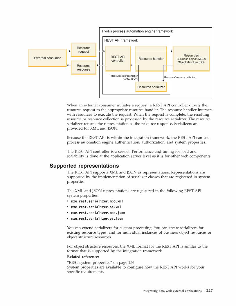
When an external consumer initiates a request, a REST API controller directs theresource request to the appropriate resource handler. The resource handler interactswith resources to execute the request. When the request is complete, the resultingresource or resource collection is processed by the resource serializer. The resourceserializer returns the representation as the resource response. Serializers areprovided for XML and JSON.
Because the REST API is within the integration framework, the REST API can useprocess automation engine authentication, authorization, and system properties.
The REST API controller is a servlet. Performance and tuning for load andscalability is done at the application server level as it is for other web components.
Supported representationsThe REST API supports XML and JSON as representations. Representations aresupported by the implementation of serializer classes that are registered in systemproperties.
The XML and JSON representations are registered in the following REST APIsystem properties:v mxe.rest.serializer.mbo.xml
v mxe.rest.serializer.os.xml
v mxe.rest.serializer.mbo.json
v mxe.rest.serializer.os.json
You can extend serializers for custom processing. You can create serializers forexisting resource types, and for individual instances of business object resources orobject structure resources.
For object structure resources, the XML format for the REST API is similar to theformat that is supported by the integration framework.Related reference:“REST system properties” on page 256System properties are available to configure how the REST API works for yourspecific requirements.
Integrating data with external applications 227
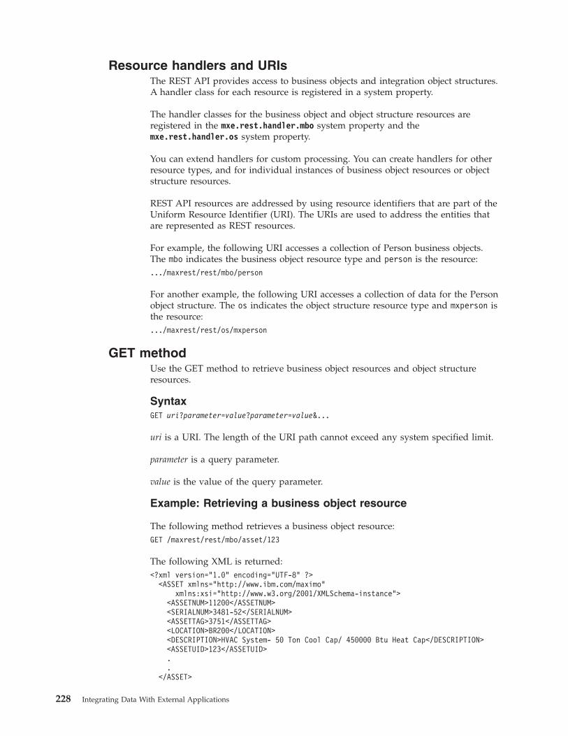
Resource handlers and URIsThe REST API provides access to business objects and integration object structures.A handler class for each resource is registered in a system property.
The handler classes for the business object and object structure resources areregistered in the mxe.rest.handler.mbo system property and themxe.rest.handler.os system property.
You can extend handlers for custom processing. You can create handlers for otherresource types, and for individual instances of business object resources or objectstructure resources.
REST API resources are addressed by using resource identifiers that are part of theUniform Resource Identifier (URI). The URIs are used to address the entities thatare represented as REST resources.
For example, the following URI accesses a collection of Person business objects.The mbo indicates the business object resource type and person is the resource:.../maxrest/rest/mbo/person
For another example, the following URI accesses a collection of data for the Personobject structure. The os indicates the object structure resource type and mxperson isthe resource:.../maxrest/rest/os/mxperson
GET methodUse the GET method to retrieve business object resources and object structureresources.
SyntaxGET uri?parameter=value?parameter=value&...
uri is a URI. The length of the URI path cannot exceed any system specified limit.
parameter is a query parameter.
value is the value of the query parameter.
Example: Retrieving a business object resource
The following method retrieves a business object resource:GET /maxrest/rest/mbo/asset/123
The following XML is returned:<?xml version="1.0" encoding="UTF-8" ?>
<ASSET xmlns="http://www.ibm.com/maximo"xmlns:xsi="http://www.w3.org/2001/XMLSchema-instance">
<ASSETNUM>11200</ASSETNUM><SERIALNUM>3481-52</SERIALNUM><ASSETTAG>3751</ASSETTAG><LOCATION>BR200</LOCATION><DESCRIPTION>HVAC System- 50 Ton Cool Cap/ 450000 Btu Heat Cap</DESCRIPTION><ASSETUID>123</ASSETUID>..
</ASSET>
228 Integrating Data With External Applications
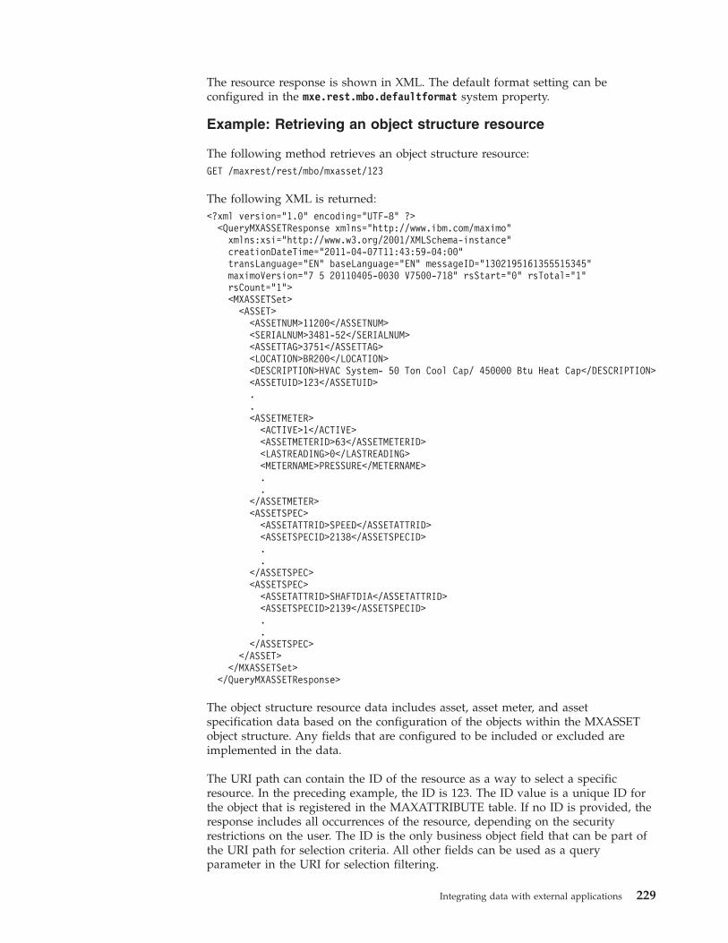
The resource response is shown in XML. The default format setting can beconfigured in the mxe.rest.mbo.defaultformat system property.
Example: Retrieving an object structure resource
The following method retrieves an object structure resource:GET /maxrest/rest/mbo/mxasset/123
The following XML is returned:<?xml version="1.0" encoding="UTF-8" ?>
<QueryMXASSETResponse xmlns="http://www.ibm.com/maximo"xmlns:xsi="http://www.w3.org/2001/XMLSchema-instance"creationDateTime="2011-04-07T11:43:59-04:00"transLanguage="EN" baseLanguage="EN" messageID="1302195161355515345"maximoVersion="7 5 20110405-0030 V7500-718" rsStart="0" rsTotal="1"rsCount="1"><MXASSETSet>
<ASSET><ASSETNUM>11200</ASSETNUM><SERIALNUM>3481-52</SERIALNUM><ASSETTAG>3751</ASSETTAG><LOCATION>BR200</LOCATION><DESCRIPTION>HVAC System- 50 Ton Cool Cap/ 450000 Btu Heat Cap</DESCRIPTION><ASSETUID>123</ASSETUID>..<ASSETMETER>
<ACTIVE>1</ACTIVE><ASSETMETERID>63</ASSETMETERID><LASTREADING>0</LASTREADING><METERNAME>PRESSURE</METERNAME>..
</ASSETMETER><ASSETSPEC>
<ASSETATTRID>SPEED</ASSETATTRID><ASSETSPECID>2138</ASSETSPECID>..
</ASSETSPEC><ASSETSPEC>
<ASSETATTRID>SHAFTDIA</ASSETATTRID><ASSETSPECID>2139</ASSETSPECID>..
</ASSETSPEC></ASSET>
</MXASSETSet></QueryMXASSETResponse>
The object structure resource data includes asset, asset meter, and assetspecification data based on the configuration of the objects within the MXASSETobject structure. Any fields that are configured to be included or excluded areimplemented in the data.
The URI path can contain the ID of the resource as a way to select a specificresource. In the preceding example, the ID is 123. The ID value is a unique ID forthe object that is registered in the MAXATTRIBUTE table. If no ID is provided, theresponse includes all occurrences of the resource, depending on the securityrestrictions on the user. The ID is the only business object field that can be part ofthe URI path for selection criteria. All other fields can be used as a queryparameter in the URI for selection filtering.
Integrating data with external applications 229
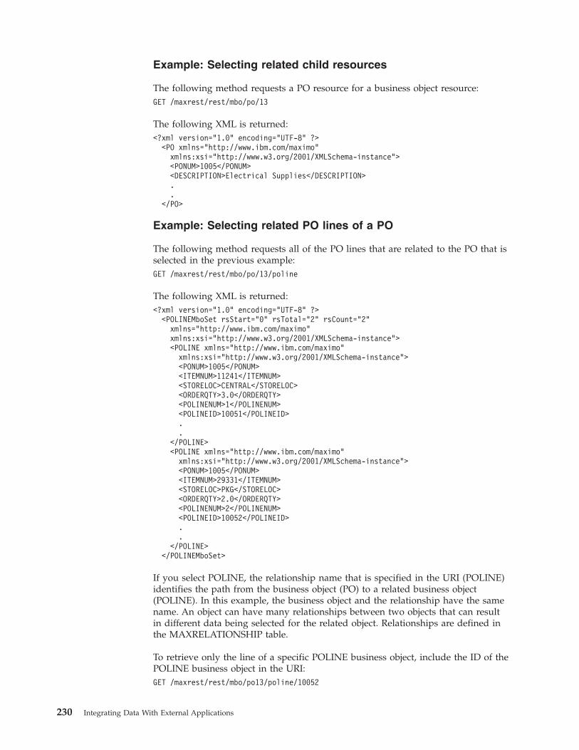
Example: Selecting related child resources
The following method requests a PO resource for a business object resource:GET /maxrest/rest/mbo/po/13
The following XML is returned:<?xml version="1.0" encoding="UTF-8" ?>
<PO xmlns="http://www.ibm.com/maximo"xmlns:xsi="http://www.w3.org/2001/XMLSchema-instance"><PONUM>1005</PONUM><DESCRIPTION>Electrical Supplies</DESCRIPTION>..
</PO>
Example: Selecting related PO lines of a PO
The following method requests all of the PO lines that are related to the PO that isselected in the previous example:GET /maxrest/rest/mbo/po/13/poline
The following XML is returned:<?xml version="1.0" encoding="UTF-8" ?>
<POLINEMboSet rsStart="0" rsTotal="2" rsCount="2"xmlns="http://www.ibm.com/maximo"xmlns:xsi="http://www.w3.org/2001/XMLSchema-instance"><POLINE xmlns="http://www.ibm.com/maximo"
xmlns:xsi="http://www.w3.org/2001/XMLSchema-instance"><PONUM>1005</PONUM><ITEMNUM>11241</ITEMNUM><STORELOC>CENTRAL</STORELOC><ORDERQTY>3.0</ORDERQTY><POLINENUM>1</POLINENUM><POLINEID>10051</POLINEID>..
</POLINE><POLINE xmlns="http://www.ibm.com/maximo"
xmlns:xsi="http://www.w3.org/2001/XMLSchema-instance"><PONUM>1005</PONUM><ITEMNUM>29331</ITEMNUM><STORELOC>PKG</STORELOC><ORDERQTY>2.0</ORDERQTY><POLINENUM>2</POLINENUM><POLINEID>10052</POLINEID>..
</POLINE></POLINEMboSet>
If you select POLINE, the relationship name that is specified in the URI (POLINE)identifies the path from the business object (PO) to a related business object(POLINE). In this example, the business object and the relationship have the samename. An object can have many relationships between two objects that can resultin different data being selected for the related object. Relationships are defined inthe MAXRELATIONSHIP table.
To retrieve only the line of a specific POLINE business object, include the ID of thePOLINE business object in the URI:GET /maxrest/rest/mbo/po13/poline/10052
230 Integrating Data With External Applications
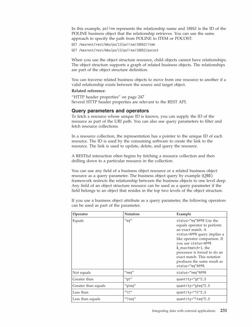
In this example, poline represents the relationship name and 10052 is the ID of thePOLINE business object that the relationship retrieves. You can use the sameapproach to specify the path from POLINE to ITEM or POCOST:GET /maxrest/rest/mbo/po/13/poline/10052/item
GET /maxrest/rest/mbo/po/13/poline/10052/pocost
When you use the object structure resource, child objects cannot have relationships.The object structure supports a graph of related business objects. The relationshipsare part of the object structure definition.
You can traverse related business objects to move from one resource to another if avalid relationship exists between the source and target object.Related reference:“HTTP header properties” on page 247Several HTTP header properties are relevant to the REST API.
Query parameters and operatorsTo fetch a resource whose unique ID is known, you can supply the ID of theresource as part of the URI path. You can also use query parameters to filter andfetch resource collections.
In a resource collection, the representation has a pointer to the unique ID of eachresource. The ID is used by the consuming software to create the link to theresource. The link is used to update, delete, and query the resource.
A RESTful interaction often begins by fetching a resource collection and thendrilling down to a particular resource in the collection.
You can use any field of a business object resource or a related business objectresource as a query parameter. The business object query by example (QBE)framework restricts the relationship between the business objects to one level deep.Any field of an object structure resource can be used as a query parameter if thefield belongs to an object that resides in the top two levels of the object structure.
If you use a business object attribute as a query parameter, the following operatorscan be used as part of the parameter.
Operator Notation Example
Equals ~eq~ status=~eq~APPR Use theequals operator to performan exact match. Astatus=APPR query implies alike operator comparison. Ifyou use status=APPR&_exactmatch=1, theprocessor is forced to do anexact match. This notationproduces the same result asstatus=~eq~APPR.
Not equals ~neq~ status=~neq~APPR
Greater than ~gt~ quantity=~gt~2.5
Greater than equals ~gteq~ quantity=~gteq~2.5
Less than ~lt~ quantity=~lt~2.5
Less than equals ~lteq~ quantity=~lteq~2.5
Integrating data with external applications 231
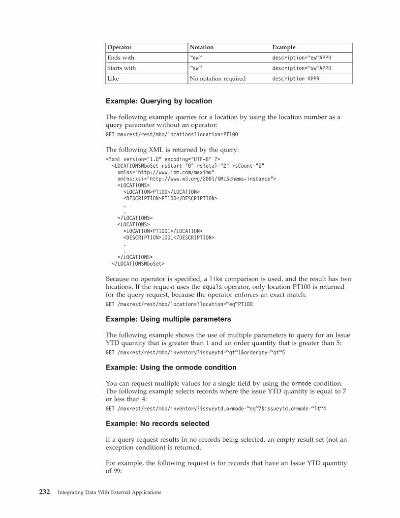
Operator Notation Example
Ends with ~ew~ description=~ew~APPR
Starts with ~sw~ description=~sw~APPR
Like No notation required description=APPR
Example: Querying by location
The following example queries for a location by using the location number as aquery parameter without an operator:GET maxrest/rest/mbo/locations?location=PT100
The following XML is returned by the query:<?xml version="1.0" encoding="UTF-8" ?>
<LOCATIONSMboSet rsStart="0" rsTotal="2" rsCount="2"xmlns="http://www.ibm.com/maximo"xmlns:xsi="http://www.w3.org/2001/XMLSchema-instance"><LOCATIONS>
<LOCATION>PT100</LOCATION><DESCRIPTION>PT100</DESCRIPTION>..
</LOCATIONS><LOCATIONS>
<LOCATION>PT1001</LOCATION><DESCRIPTION>1001</DESCRIPTION>..
</LOCATIONS></LOCATIONSMboSet>
Because no operator is specified, a like comparison is used, and the result has twolocations. If the request uses the equals operator, only location PT100 is returnedfor the query request, because the operator enforces an exact match:GET /maxrest/rest/mbo/locations?location=~eq~PT100
Example: Using multiple parameters
The following example shows the use of multiple parameters to query for an IssueYTD quantity that is greater than 1 and an order quantity that is greater than 5:GET /maxrest/rest/mbo/inventory?issueytd=~gt~1&orderqty=~gt~5
Example: Using the ormode condition
You can request multiple values for a single field by using the ormode condition.The following example selects records where the issue YTD quantity is equal to 7or less than 4:GET /maxrest/rest/mbo/inventory?issueytd.ormode=~eq~7&issueytd.ormode=~lt~4
Example: No records selected
If a query request results in no records being selected, an empty result set (not anexception condition) is returned.
For example, the following request is for records that have an Issue YTD quantityof 99:
232 Integrating Data With External Applications
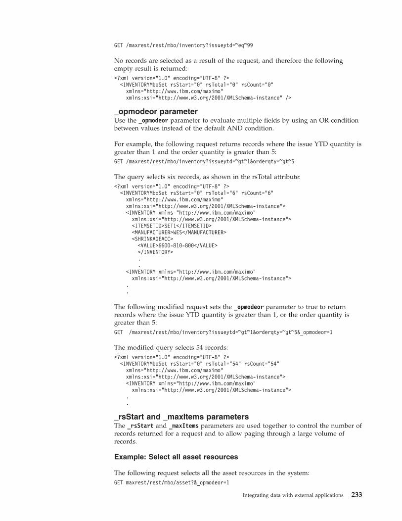
GET /maxrest/rest/mbo/inventory?issueytd=~eq~99
No records are selected as a result of the request, and therefore the followingempty result is returned:<?xml version="1.0" encoding="UTF-8" ?>
<INVENTORYMboSet rsStart="0" rsTotal="0" rsCount="0"xmlns="http://www.ibm.com/maximo"xmlns:xsi="http://www.w3.org/2001/XMLSchema-instance" />
_opmodeor parameterUse the _opmodeor parameter to evaluate multiple fields by using an OR conditionbetween values instead of the default AND condition.
For example, the following request returns records where the issue YTD quantity isgreater than 1 and the order quantity is greater than 5:GET /maxrest/rest/mbo/inventory?issueytd=~gt~1&orderqty=~gt~5
The query selects six records, as shown in the rsTotal attribute:<?xml version="1.0" encoding="UTF-8" ?>
<INVENTORYMboSet rsStart="0" rsTotal="6" rsCount="6"xmlns="http://www.ibm.com/maximo"xmlns:xsi="http://www.w3.org/2001/XMLSchema-instance"><INVENTORY xmlns="http://www.ibm.com/maximo"
xmlns:xsi="http://www.w3.org/2001/XMLSchema-instance"><ITEMSETID>SET1</ITEMSETID><MANUFACTURER>WES</MANUFACTURER><SHRINKAGEACC>
<VALUE>6600-810-800</VALUE></INVENTORY>..
<INVENTORY xmlns="http://www.ibm.com/maximo"xmlns:xsi="http://www.w3.org/2001/XMLSchema-instance">
.
.
The following modified request sets the _opmodeor parameter to true to returnrecords where the issue YTD quantity is greater than 1, or the order quantity isgreater than 5:GET /maxrest/rest/mbo/inventory?issueytd=~gt~1&orderqty=~gt~5&_opmodeor=1
The modified query selects 54 records:<?xml version="1.0" encoding="UTF-8" ?>
<INVENTORYMboSet rsStart="0" rsTotal="54" rsCount="54"xmlns="http://www.ibm.com/maximo"xmlns:xsi="http://www.w3.org/2001/XMLSchema-instance"><INVENTORY xmlns="http://www.ibm.com/maximo"
xmlns:xsi="http://www.w3.org/2001/XMLSchema-instance">..
_rsStart and _maxItems parametersThe _rsStart and _maxItems parameters are used together to control the number ofrecords returned for a request and to allow paging through a large volume ofrecords.
Example: Select all asset resources
The following request selects all the asset resources in the system:GET maxrest/rest/mbo/asset?&_opmodeor=1
Integrating data with external applications 233
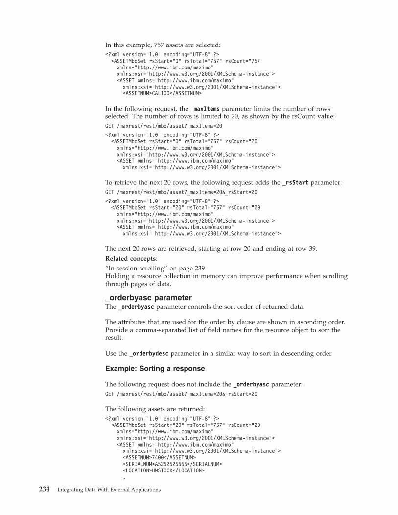
In this example, 757 assets are selected:<?xml version="1.0" encoding="UTF-8" ?>
<ASSETMboSet rsStart="0" rsTotal="757" rsCount="757"xmlns="http://www.ibm.com/maximo"xmlns:xsi="http://www.w3.org/2001/XMLSchema-instance"><ASSET xmlns="http://www.ibm.com/maximo"
xmlns:xsi="http://www.w3.org/2001/XMLSchema-instance"><ASSETNUM>CAL100</ASSETNUM>
In the following request, the _maxItems parameter limits the number of rowsselected. The number of rows is limited to 20, as shown by the rsCount value:GET /maxrest/rest/mbo/asset?_maxItems=20
<?xml version="1.0" encoding="UTF-8" ?><ASSETMboSet rsStart="0" rsTotal="757" rsCount="20"
xmlns="http://www.ibm.com/maximo"xmlns:xsi="http://www.w3.org/2001/XMLSchema-instance"><ASSET xmlns="http://www.ibm.com/maximo"
xmlns:xsi="http://www.w3.org/2001/XMLSchema-instance">
To retrieve the next 20 rows, the following request adds the _rsStart parameter:GET /maxrest/rest/mbo/asset?_maxItems=20&_rsStart=20
<?xml version="1.0" encoding="UTF-8" ?><ASSETMboSet rsStart="20" rsTotal="757" rsCount="20"
xmlns="http://www.ibm.com/maximo"xmlns:xsi="http://www.w3.org/2001/XMLSchema-instance"><ASSET xmlns="http://www.ibm.com/maximo"
xmlns:xsi="http://www.w3.org/2001/XMLSchema-instance">
The next 20 rows are retrieved, starting at row 20 and ending at row 39.Related concepts:“In-session scrolling” on page 239Holding a resource collection in memory can improve performance when scrollingthrough pages of data.
_orderbyasc parameterThe _orderbyasc parameter controls the sort order of returned data.
The attributes that are used for the order by clause are shown in ascending order.Provide a comma-separated list of field names for the resource object to sort theresult.
Use the _orderbydesc parameter in a similar way to sort in descending order.
Example: Sorting a response
The following request does not include the _orderbyasc parameter:GET /maxrest/rest/mbo/asset?_maxItems=20&_rsStart=20
The following assets are returned:<?xml version="1.0" encoding="UTF-8" ?>
<ASSETMboSet rsStart="20" rsTotal="757" rsCount="20"xmlns="http://www.ibm.com/maximo"xmlns:xsi="http://www.w3.org/2001/XMLSchema-instance"><ASSET xmlns="http://www.ibm.com/maximo"
xmlns:xsi="http://www.w3.org/2001/XMLSchema-instance"><ASSETNUM>7400</ASSETNUM><SERIALNUM>A5252525555</SERIALNUM><LOCATION>HWSTOCK</LOCATION>.
234 Integrating Data With External Applications
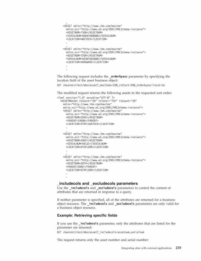
.<ASSET xmlns="http://www.ibm.com/maximo"
xmlns:xsi="http://www.w3.org/2001/XMLSchema-instance"><ASSETNUM>7300</ASSETNUM><SERIALNUM>A6687688888</SERIALNUM><LOCATION>HWSTOCK</LOCATION>..
<ASSET xmlns="http://www.ibm.com/maximo"xmlns:xsi="http://www.w3.org/2001/XMLSchema-instance"><ASSETNUM>7200</ASSETNUM><SERIALNUM>A6387683888</SERIALNUM><LOCATION>HARDWARE</LOCATION>..
The following request includes the _orderbyasc parameter by specifying thelocation field of the asset business object:GET /maxrest/rest/mbo/asset?_maxItems=20&_rsStart=20&_orderbyasc=location
The modified request returns the following assets in the requested sort order:<?xml version="1.0" encoding="UTF-8" ?>
<ASSETMboSet rsStart="20" rsTotal="757" rsCount="20"xmlns="http://www.ibm.com/maximo"xmlns:xsi="http://www.w3.org/2001/XMLSchema-instance"><ASSET xmlns="http://www.ibm.com/maximo"
xmlns:xsi="http://www.w3.org/2001/XMLSchema-instance"><ASSETNUM>2045</ASSETNUM><PARENT>19998</PARENT><LOCATION>5THFLSWSTOCK</LOCATION>..
<ASSET xmlns="http://www.ibm.com/maximo"xmlns:xsi="http://www.w3.org/2001/XMLSchema-instance"><ASSETNUM>2002</ASSETNUM><SERIALNUM>K6LQI</SERIALNUM><LOCATION>6THFLOOR</LOCATION>..
<ASSET xmlns="http://www.ibm.com/maximo"xmlns:xsi="http://www.w3.org/2001/XMLSchema-instance"><ASSETNUM>2074</ASSETNUM><PARENT>2002</PARENT><LOCATION>6THFLOOR</LOCATION>..
_includecols and _excludecols parametersUse the _includecols and _excludecols parameters to control the content ofattributes that are returned in response to a query.
If neither parameter is specified, all of the attributes are returned for a businessobject resource. The _includecols and _excludecols parameters are only valid fora business object resource.
Example: Retrieving specific fields
If you use the _includecols parameter, only the attributes that are listed for theparameter are returned:GET /maxrest/rest/mbo/asset?_includecols=assetnum,serialnum
The request returns only the asset number and serial number:
Integrating data with external applications 235
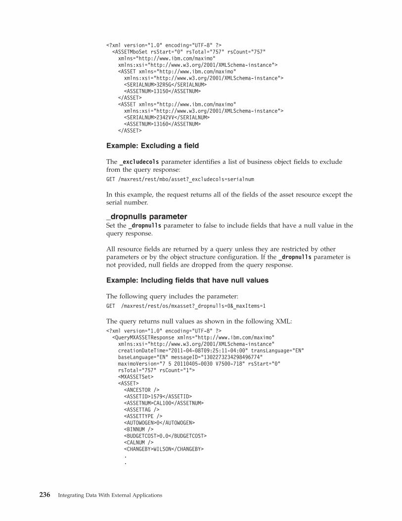
<?xml version="1.0" encoding="UTF-8" ?><ASSETMboSet rsStart="0" rsTotal="757" rsCount="757"
xmlns="http://www.ibm.com/maximo"xmlns:xsi="http://www.w3.org/2001/XMLSchema-instance"><ASSET xmlns="http://www.ibm.com/maximo"
xmlns:xsi="http://www.w3.org/2001/XMLSchema-instance"><SERIALNUM>32R5G</SERIALNUM><ASSETNUM>13150</ASSETNUM>
</ASSET><ASSET xmlns="http://www.ibm.com/maximo"
xmlns:xsi="http://www.w3.org/2001/XMLSchema-instance"><SERIALNUM>2342VV</SERIALNUM><ASSETNUM>13160</ASSETNUM>
</ASSET>
Example: Excluding a field
The _excludecols parameter identifies a list of business object fields to excludefrom the query response:GET /maxrest/rest/mbo/asset?_excludecols=serialnum
In this example, the request returns all of the fields of the asset resource except theserial number.
_dropnulls parameterSet the _dropnulls parameter to false to include fields that have a null value in thequery response.
All resource fields are returned by a query unless they are restricted by otherparameters or by the object structure configuration. If the _dropnulls parameter isnot provided, null fields are dropped from the query response.
Example: Including fields that have null values
The following query includes the parameter:GET /maxrest/rest/os/mxasset?_dropnulls=0&_maxItems=1
The query returns null values as shown in the following XML:<?xml version="1.0" encoding="UTF-8" ?>
<QueryMXASSETResponse xmlns="http://www.ibm.com/maximo"xmlns:xsi="http://www.w3.org/2001/XMLSchema-instance"creationDateTime="2011-04-08T09:25:11-04:00" transLanguage="EN"baseLanguage="EN" messageID="1302273234298496774"maximoVersion="7 5 20110405-0030 V7500-718" rsStart="0"rsTotal="757" rsCount="1"><MXASSETSet><ASSET>
<ANCESTOR /><ASSETID>1579</ASSETID><ASSETNUM>CAL100</ASSETNUM><ASSETTAG /><ASSETTYPE /><AUTOWOGEN>0</AUTOWOGEN><BINNUM /><BUDGETCOST>0.0</BUDGETCOST><CALNUM /><CHANGEBY>WILSON</CHANGEBY>..
236 Integrating Data With External Applications
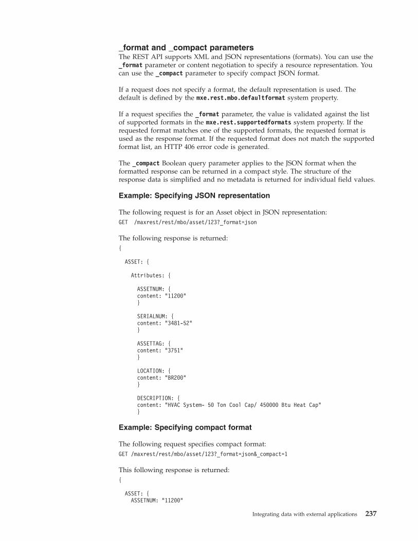
_format and _compact parametersThe REST API supports XML and JSON representations (formats). You can use the_format parameter or content negotiation to specify a resource representation. Youcan use the _compact parameter to specify compact JSON format.
If a request does not specify a format, the default representation is used. Thedefault is defined by the mxe.rest.mbo.defaultformat system property.
If a request specifies the _format parameter, the value is validated against the listof supported formats in the mxe.rest.supportedformats system property. If therequested format matches one of the supported formats, the requested format isused as the response format. If the requested format does not match the supportedformat list, an HTTP 406 error code is generated.
The _compact Boolean query parameter applies to the JSON format when theformatted response can be returned in a compact style. The structure of theresponse data is simplified and no metadata is returned for individual field values.
Example: Specifying JSON representation
The following request is for an Asset object in JSON representation:GET /maxrest/rest/mbo/asset/123?_format=json
The following response is returned:{
ASSET: {
Attributes: {
ASSETNUM: {content: "11200"}
SERIALNUM: {content: "3481-52"}
ASSETTAG: {content: "3751"}
LOCATION: {content: "BR200"}
DESCRIPTION: {content: "HVAC System- 50 Ton Cool Cap/ 450000 Btu Heat Cap"}
Example: Specifying compact format
The following request specifies compact format:GET /maxrest/rest/mbo/asset/123?_format=json&_compact=1
This following response is returned:{
ASSET: {ASSETNUM: "11200"
Integrating data with external applications 237
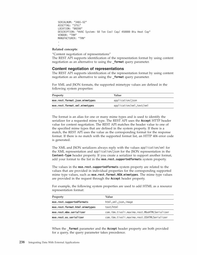
SERIALNUM: "3481-52"ASSETTAG: "3751"LOCATION: "BR200"DESCRIPTION: "HVAC System- 50 Ton Cool Cap/ 450000 Btu Heat Cap"VENDOR: "TRN"MANUFACTURER: "TRN"..
Related concepts:“Content negotiation of representations”The REST API supports identification of the representation format by using contentnegotiation as an alternative to using the _format query parameter.
Content negotiation of representationsThe REST API supports identification of the representation format by using contentnegotiation as an alternative to using the _format query parameter.
For XML and JSON formats, the supported mimetype values are defined in thefollowing system properties:
Property Value
mxe.rest.format.json.mimetypes application/json
mxe.rest.format.xml.mimetypes application/xml,text/xml
The format is an alias for one or many mime types and is used to identify theserializer for a requested mime type. The REST API uses the Accept HTTP headervalue for content negotiation. The REST API matches the header value to one ofthe specified mime types that are defined in the system property. If there is amatch, the REST API uses the value as the corresponding format for the responseformat. If there is no match with the supported format list, an HTTP 406 error codeis generated.
The XML and JSON serializers always reply with the values application/xml forthe XML representation and application/json for the JSON representation in theContent-Type header property. If you create a serializer to support another format,add your format to the list in the mxe.rest.supportedformats system property.
The values in the mxe.rest.supportedformats system property are related to thevalues that are provided in individual properties for the corresponding supportedmime type values, such as mxe.rest.format.NEW.mimetypes. The mime type valuesare provided in the request through the Accept header property.
For example, the following system properties are used to add HTML as a resourcerepresentation format:
Property Value
mxe.rest.supportedformats html,xml,json,image
mxe.rest.format.html.mimetypes text/html
mxe.rest.mbo.serializer com.ibm.tivoli.maximo.rest.MboHTMLSerializer
mxe.rest.os.serializer com.ibm.tivoli.maximo.rest.OSHTMLSerializer
When the _format parameter and the Accept header property are both providedfor a query, the query parameter takes precedence.
238 Integrating Data With External Applications
Related concepts:“_format and _compact parameters” on page 237The REST API supports XML and JSON representations (formats). You can use the_format parameter or content negotiation to specify a resource representation. Youcan use the _compact parameter to specify compact JSON format.
In-session scrollingHolding a resource collection in memory can improve performance when scrollingthrough pages of data.
If you specify the _usc parameter with a value of 1 in a query, the server holds theresource collection in memory. The browser can request additional pages of datafrom memory instead of reselecting the data from the business object. The HTTPresponse includes the ID of the resource collection in the RLID header property.
Subsequent requests for additional pages of data can specify the _maxitemparameter, _rsStart parameter, and _rlid parameter, which holds the ID of theresource collection. The server retrieves the next page from the data that is held inmemory for the specified ID.
The server cache data is held until the browser session ends or until the browserreleases the data. For example, the data is released if the ID of the resource isspecified by the _rlid parameter and the _rlrq parameter is set to true.
As an alternative to using the _maxitems and _rsStart parameters for in-sessionscrolling, you can create a mxe.rest.handler.resource.pagesize system property andassign to it a number of resources for each page of data. You can then use the_page query parameter in the request to select a specific page of data, such as page3.
For example, if you create the mxe.rest.mbo.asset.pagesize system property andassign it the value 35, 35 assets are returned for each page of data.Related concepts:“_rsStart and _maxItems parameters” on page 233The _rsStart and _maxItems parameters are used together to control the number ofrecords returned for a request and to allow paging through a large volume ofrecords.Related reference:“HTTP header properties” on page 247Several HTTP header properties are relevant to the REST API.“REST query parameters” on page 252By using query parameters, you can tailor and filter the responses.
Caching of GET requestsBy enabling the caching of GET requests, you can improve the response times ofrequests for resource data that were previously submitted by the same user.
When caching is enabled, the data is retrieved from the browser cache instead offrom the business object on the server. Caching is used for a request if the entitytag (ETag) value of the request matches the value of the previous request. Cachingis unique to each user and is controlled by the Cache-Control HTTP headerproperty.
Integrating data with external applications 239
Enabling caching
You enable caching for individual resources by creating system properties. Thesystem properties must be in the form mxe.rest.handler.resource.cache, wherehandler is mbo or os and resource is the name of the business object or objectstructure. The system properties must have a Boolean value of 1.
For example, the system property mxe.rest.mbo.workorder.cache set to a value of1 enables caching for the work order business object.
Entity tag calculations and comparisons
When an initial request is made for a resource and caching is enabled for theresource, the framework generates an ETag value for the resource response. TheETag is calculated based on the MBO rowstamp attribute, which changes any timean MBO is modified. For a resource collection, the ETag is calculated based on ahash of the collection of rowstamp values from the MBOs in the collection.
For example, the response contains the following in the HTTP header:HTTP/1.1 200 OKETag: "123456789"Cache-control: privateContent-Length: 12195
The Cache-control is marked as private to ensure that only the current user canreuse the contents of the cache.
When the user makes a repeat request for the same resource or collection, therequest is similar to the following:GET maxrest/rest/mbo/po HTTP/1.1Host: x.yIf-None-Match: "123456789"
The If-None-Match value is the ETag value from the previous request. Theframework reads the If-None-Match header value and compares it to the newcalculated ETag value for the resource or collection for the second request. If thevalues match, the server responds with an HTTP 304, implying that the clientcache content is valid and can be used. The response includes the following line:HTTP/1.1 304 Not Modified
If the ETag value does not match the If-None-Match header value of the request,the resource representation is constructed and sent to the client with a new ETagvalue to be used by the client for subsequent requests for the resource orcollection:HTTP/1.1 200 OKETag: "98999999"Cache-control: privateContent-Length: 50004
Pessimistic caching mode
The default caching mode is pessimistic caching. In pessimistic caching mode,requests are serialized but the data is not sent from the server to the client whenthe ETag value of the request matches the value of the previous request.
240 Integrating Data With External Applications
Optimistic caching mode
You can enable optimistic caching by setting themxe.rest.handler.resource.optimistic system property to 1. In optimistic cachingmode, the ETag value is calculated before any data serialization occurs. Althoughoptimistic caching can improve response times significantly because noserialization occurs, it requires more memory, especially for queries that requestmany records.
By default, optimistic caching determines the ETag value from the root object of anobject structure. Therefore, if an object structure has related objects that do notupdate the root object, the ETag value might not be accurate. You can ensure thatthe ETag value is determined from all the objects in the object structure, includingrelated objects, by setting the mxe.rest.handler.resource.deepetag system propertyto 1. However, by using this system property, the performance improvement is notas great and more memory is used.
Cache time limits
You can configure the length of time that the cache is valid for by setting themxe.rest.handler.resource.maxage system property to a value measured in seconds.Related reference:“HTTP header properties” on page 247Several HTTP header properties are relevant to the REST API.“REST system properties” on page 256System properties are available to configure how the REST API works for yourspecific requirements.
PUT, POST, and DELETE methodsYou can modify resources by using the HTTP PUT, POST, and DELETE methods.
The PUT, POST, and DELETE methods can be used to modify business objectresources and object structure resources. However, the business rules of an objectmight prevent it from being updated by a REST API request. For example, aDELETE request on a work order resource might fail if the business objectvalidations prevent deletions because of the current state of the work order.
Syntaxmethod uri HTTP/1.1parameter=value¶meter=value&...
method is PUT, POST, or DELETE
uri is a URI and any associated query parameters
parameter is a parameter of the resource that is updated
value is the value of the parameter
PUT methodUse the PUT method to update or insert a resource. An update request mustprovide the unique ID of the resource. To update an object structure resource, theID of the main object is required.
Integrating data with external applications 241
To update or insert an object structure resource, you can specify the _actionparameter to identify actions that the integration framework provides, such as theChange or AddChange actions.
Example: Updating an asset
The following method updates the asset that has an ID of 1234. The assetdescription is changed to my_new_description and the type is changed toOPERATING:PUT maxrest/rest/mbo/asset/1234 HTTP/1.1description=my_new_description&type=OPERATING
Example: Updating a child object
The following method updates the assetspec business object, which is a child ofasset. The value is changed to new_value and the description is changed tomy_new_description:PUT maxrest/rest/mbo/assetspec/5678 HTTP/1.1value=my_new_value&description=my_new_description
Example: Establishing the context of a parent object
To insert or update a child business object, you might need to establish the contextof the parent business object context, such as in the following example in which aPO line description is updated and the ID of the PO is provided for context:PUT maxrest/rest/mbo/po/1234/poline/5678 HTTP/1.1description=my_new_description
POST methodUse the POST method to update or insert a resource.
To update a resource, you must specify the ID of the resource. To create a resource,you must specify the primary key and all the required fields that do not have adefault value, but no ID is required.
To update or insert an object structure resource, you can specify the _actionparameter to identify actions that the integration framework provides, such asChange or AddChange.
To update or insert a child object of an object structure resource, the form datamust identify each occurrence of the child object.
When you use the POST method to create a resource, specify the _ulcr queryparameter with a value of 1 so that the response includes a link for the client toaccess the new resource. Otherwise, the content of the resource is included in theresponse. The link is included in the Location header property and the HTTPresponse code is 201 to identify that a link is provided instead of the data.
Example: Inserting an asset
The following method inserts asset 127 within the BEDFORD site by using abusiness object resource. The asset and site make up the primary key.POST maxrest/rest/mbo/asset HTTP/1.1assetnum=127&siteid=BEDFORD&description=my_new_description&type=OPERATING
242 Integrating Data With External Applications
Example: Updating an asset by specifying its ID
The following method updates an asset by providing the ID as part of the URI:POST maxrest/rest/mbo/asset/1234 HTTP/1.1description=my_new_description&type=OPERATING
Example: Specifying an action
The following method uses the _action parameter to specify a Change action:POST maxrest/rest/mbo/asset/968 HTTP/1.1_action=Change&description=my_new_description
Example: Updating a record that has multiple child objects
The following method adds two purchase order lines to a purchase order, and eachline has two purchase order costs:
POST maxrest/rest/os/mxpo/1234 HTTP/1.1description=new_po_desc&poline.id1.polinenum=1&poline.id1.item=ABC&poline.id1.description=new_description&poline.id1.pocost.id1-1.costlinenum=1&poline.id1.pocost.id1-1.gldebitacct=new_gl_acct_a&poline.id1.pocost.id1-2.costlinenum=2&poline.id1.pocost.id1-2.gldebitacct=new_gl_acct_b&poline.id2.polinenum=2&poline.id2.item=XYZ&poline.id2.description=new_description&poline.id2.pocost.id2-1.costlinenum=1&poline.id2.pocost.id2-1.gldebitacct=new_gl_acct_c&poline.id2.pocost.id2-2.costlinenum=2&poline.id2.pocost.id2-2.gldebitacct=new_gl_acct_d&
In the example, the identifiers identify the following parameters:
Group identifier Parameters identified
id1 Parameters that belong to poline 1
id1-1 Parameters that belong to pocost 1 for poline 1
id1-2 Parameters that belong to pocost 2 for poline 1
id2 Parameters that belong to poline 2
id2-1 Parameters that belong to pocost 1 for poline 2
id2-2 Parameters that belong to pocost 2 for poline 2
Related reference:“HTTP header properties” on page 247Several HTTP header properties are relevant to the REST API.
DELETE methodThe DELETE method requires the unique ID of the resource.
To delete an object structure resource, the ID of the main object is required.
Example: Deleting an asset
The following method deletes asset 1234:DELETE maxrest/rest/mbo/asset/1234 HTTP/1.1
Concurrent updates of resourcesProcessing can be controlled so that a resource is updated or deleted only if theresource has not been changed by another user or application after the initialquery.
Integrating data with external applications 243
If the _urs parameter is set to a value of 1, the query response includes therowstamp value for the resource.
XML example:<PO rowstamp=1234567890>
JSON example:{"ASSET":{"rowstamp":"1234567890","Attributes":{"ASSETNUM":{"content":"1001"}
JSON example in compact format:{"ASSET":{"rowstamp":"1234567890","ASSETNUM":"1001",
For an object structure resource, a rowstamp value is provided for each object thatis in the object structure.
On a subsequent request to update the resource, the rowstamp value can beprovided by using the _rowstamp parameter for business object and object structureresources, or by specifying the If-Match header property for business objects.
During processing, the rowstamp value is compared to the initial rowstamp. If thevalues do not match, the update or delete operation fails and an HTTP return codeof 412 is in the response.
Service method queries and updatesThe REST API can be used to call methods that are exposed by applicationservices.
Methods that are exposed by application services are typically marked with theJava Specification Request (JSR) 181 @WebMethod annotation, which exposes themas web service methods. The REST API provides a resource-oriented view intothese service methods.
The service methods are in the following categories:v Methods that create, update, or delete resources by using the HTTP POST
method and modify the system state by doing so.v Methods that fetch resources or collections of resources by using the HTTP GET
method and do not modify the system state.v Methods that return system information, such as date or version information, by
using the HTTP GET method and do not access resources.
Service methods that use HTTP POST to update resourcesMethods can create, update, or delete resources by using the HTTP POST method.
Methods that update resources modify the system state.
The X-HTTP-Method-Override (XMO) header qualifies the HTTP POST. The XMOheader contains the name of the method that is exposed by the JSR 181 annotation.
The REST framework looks up the service that owns the resource, finds themethod that is identified in the XMO header, deserializes the POST formparameters, calls the method, and returns the serialized representation of themodified resource.
244 Integrating Data With External Applications
Example: Annotating a method
For example, the ASSET service has the annotated moveSingleAsset businessmethod:@WebMethodpublic void moveSingleAsset(@WSMboKey("ASSET") MboRemote asset, String newLocation,
String newSite, String newParent) throws MXException, RemoteException
The method moves an asset from its current location to a new location andtherefore modifies the state of the system. The following request is used to call themethod:POST maxrest/rest/mbo/asset/1234 HTTP/1.1x-http-method-override: "moveSingleAsset"
The form data request is the following:~asset=this&~newLocation=Some_where&~newSite=some_site&~newParent=Some_one
When the request is made, the following occurs:1. The asset business object that has the identifier 1234 is loaded.2. The owning service (ASSET) is looked up.3. The method that is named moveSingleAsset is found.4. The asset that is in the URI is referenced to the ASSET business object by the
@WSMboKey annotation, and the business object is provided as the firstparameter value in the form data request.
5. The remaining values are deserialized and assigned, based on their names.6. The modified asset 1234 is returned to the client in the requested
representation.
Example: Overriding a method parameter name
The form parameter names are the same as the method parameter names, prefixedwith the ~ (tilde) character, unless they are annotated with the@WebParam(name="...") annotation.
For example, consider a case where the method definition has an operation namedefined in the annotation:@WebMethod(operationName="moveAssetLocation")public void moveSingleAsset(...)
In this case, the following request is used to call the method:POST maxrest/rest/mbo/asset/1234 HTTP/1.1x-method-override: "moveAssetLocation"
The form data request is the following:~asset=this&~newLocation=Some_where&~newSite=some_site&~newParent=Some_one
The XMO header value must use the attribute value specified in the @WebMethodannotation: moveAssetLocation.
Service methods that use HTTP GET to query resourcesA method name or annotated operation name that starts with the keyword get canbe accessed by the HTTP GET method.
Integrating data with external applications 245
For example, the following method from the LOGGING service returns the list ofMAXLOGGER business objects as a business object set:@WebMethod@WSMboSet(name="MAXLOGGER")public MboSetRemote getLoggerList()
The following request is used to call the method and returns the collection ofbusiness objects in the configured representation:GET maxrest/rest/mbo/maxlogger?_qop=getLoggerList HTTP/1.1
In the following variation of the method, an operation name is provided:@WebMethod(operationName=”getFilteredLoggers”)@WSMboSet(name="MAXLOGGER")public MboSetRemote getLoggerList(String someFilter)
The following request is used to call the method:GET maxrest/rest/mbo/maxlogger?_qop=getFilteredLoggers&~someFilter=... HTTP/1.1
The _qop value specifies the annotated name. The someFilter parameter is prefixedwith the ~ character as part of the request.
Virtual methods
If a method name does not start with the keyword get, it cannot be called directly.For example, if a client tries to call the moveSingleAsset operation by using HTTPGET, an HTTP 405 error is thrown. However, you can define a virtual method byusing a system property.
For example, suppose you create the propertymxe.rest.mbo.maxqueue.action.getQueueData and assign it the value_operation=viewQueue|~queueName=this.queuename.
For the maxqueue resource, the virtual method getQueueData maps to theviewQueue operation in the owning service of maxqueue, which is the MICservice. The | (pipe) character separates the attributes. You can therefore access theviewQueue operation by using the following HTTP GET call:GET /maxrest/rest/mbo/maxqueue/4567?_qop=getQueueData&~selector=...&~count=-1
You can specify literal or derived values for a method parameter.
For example, the viewQueue method has a parameter queueName that maps to themaxqueue.queuename attribute. The maxqueue is the business object in the currentcontext that is specified by the GET URI. Therefore, the framework evaluates thederived value this.queuename as current_mbo_in_context.queuename, which is thevalue of the queuename attribute of maxqueue that is identified by the unique ID4567.
As a second example, suppose you create the mxe.rest.mbo.po.action.approvesystem property and assign it the value _operation=changeStatus|~status=APPR.
A virtual operation called approve is created and it maps to the operation calledchangeStatus on PO, which is the owner service of the PO business object. Forsimplicity in the example, the value for the status parameter is hardcoded toAPPR. The hardcoded value would not be practical because the status parametervalue must be translatable.
246 Integrating Data With External Applications
If you use virtual methods, you must ensure that HTTP GET methods do not mapto operations that modify the system state or have any other side effects.
Predefined initiateWorkflow operation
The predefined operation initiateWorkflow initiates a workflow for a businessobject resource. The following two examples use this operation:POST /maxrest/rest/mbo/po/6789 HTTP/1.1x-http-method-override: "initiateWorkflow"
wfname=SOMEWF
POST /maxrest/rest/mbo/po/6789?wfname=SOMEWF HTTP/1.1x-http-method-override: "initiateWorkflow"
The method initiates the active revision of a workflow named SOMEWF for thepurchase order business object that has the unique ID 6789. If the workflow has await node or a task node, it might require other steps or a background event torestart it, which is outside the scope of the REST API.
Service methods that use HTTP GET to query system dataSome service operations retrieve system data and are not resource-oriented.
For example, the following HTTP GET retrieves the date and time:GET /maxrest/rest/ss/system/getDate
The following XML is returned:<getDateResponse xmlns=....><result>some ISO 8601 date</result></getDateResponse>
For another example, the following HTTP GET returns version information:GET /maxrest/rest/ssm/system/getMXServerVersion
The following XML is returned:<getMXServerVersionResponse xmlns=...><return>Tivoli’s process automation engine 7.5.0.0 Build 20110127-1121DB Build V7500-673</return><return>...</return></getMXServerVersionResponse>
To obtain a list of all services you can use the following GET method:GET /maxrest/rest/ss
You can then drill down to each of the services in the list to get a list of operationsthat can be called. For example, the following method returns the operations forthe service that is called system:GET /maxrest/rest/ss/system
HTTP header propertiesSeveral HTTP header properties are relevant to the REST API.
Table 35. REST API HTTP header properties
Property Description
Accept Provided by the requester and used for content negotiation todetermine the response format of the request.
Integrating data with external applications 247
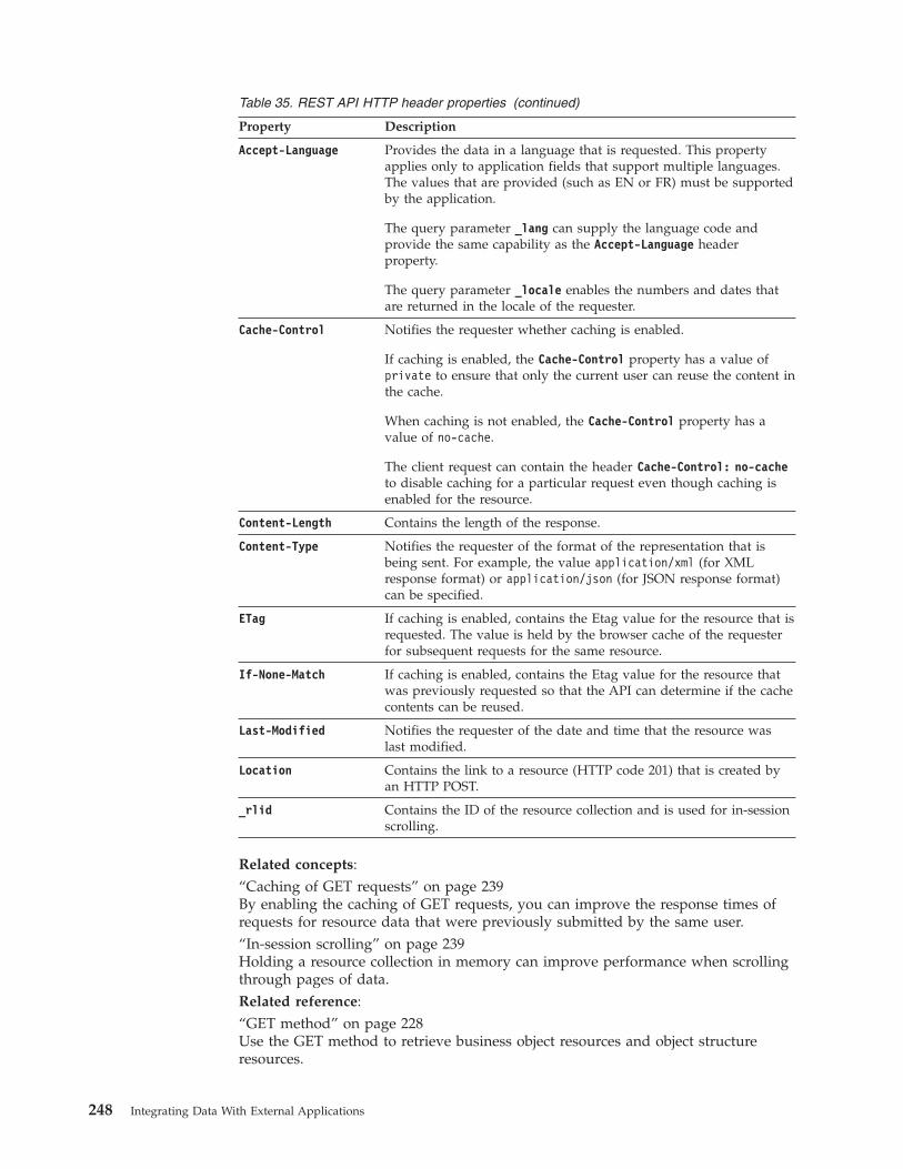
Table 35. REST API HTTP header properties (continued)
Property Description
Accept-Language Provides the data in a language that is requested. This propertyapplies only to application fields that support multiple languages.The values that are provided (such as EN or FR) must be supportedby the application.
The query parameter _lang can supply the language code andprovide the same capability as the Accept-Language headerproperty.
The query parameter _locale enables the numbers and dates thatare returned in the locale of the requester.
Cache-Control Notifies the requester whether caching is enabled.
If caching is enabled, the Cache-Control property has a value ofprivate to ensure that only the current user can reuse the content inthe cache.
When caching is not enabled, the Cache-Control property has avalue of no-cache.
The client request can contain the header Cache-Control: no-cacheto disable caching for a particular request even though caching isenabled for the resource.
Content-Length Contains the length of the response.
Content-Type Notifies the requester of the format of the representation that isbeing sent. For example, the value application/xml (for XMLresponse format) or application/json (for JSON response format)can be specified.
ETag If caching is enabled, contains the Etag value for the resource that isrequested. The value is held by the browser cache of the requesterfor subsequent requests for the same resource.
If-None-Match If caching is enabled, contains the Etag value for the resource thatwas previously requested so that the API can determine if the cachecontents can be reused.
Last-Modified Notifies the requester of the date and time that the resource waslast modified.
Location Contains the link to a resource (HTTP code 201) that is created byan HTTP POST.
_rlid Contains the ID of the resource collection and is used for in-sessionscrolling.
Related concepts:“Caching of GET requests” on page 239By enabling the caching of GET requests, you can improve the response times ofrequests for resource data that were previously submitted by the same user.“In-session scrolling” on page 239Holding a resource collection in memory can improve performance when scrollingthrough pages of data.Related reference:“GET method” on page 228Use the GET method to retrieve business object resources and object structureresources.
248 Integrating Data With External Applications
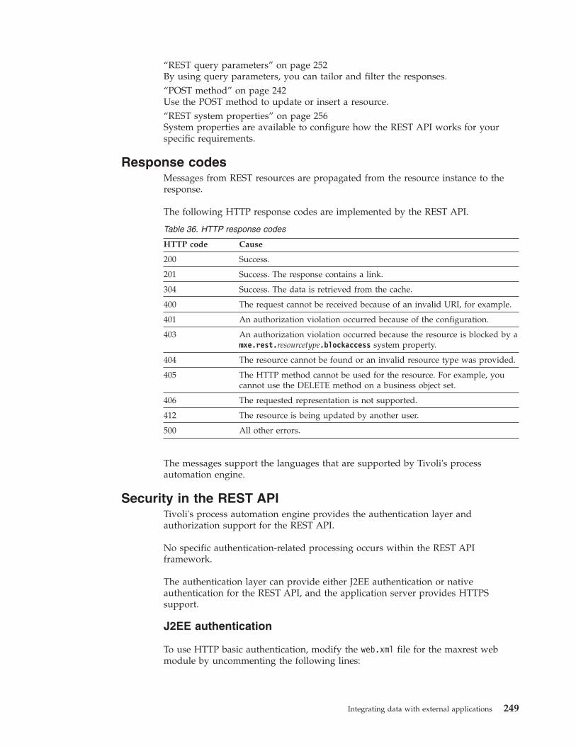
“REST query parameters” on page 252By using query parameters, you can tailor and filter the responses.“POST method” on page 242Use the POST method to update or insert a resource.“REST system properties” on page 256System properties are available to configure how the REST API works for yourspecific requirements.
Response codesMessages from REST resources are propagated from the resource instance to theresponse.
The following HTTP response codes are implemented by the REST API.
Table 36. HTTP response codes
HTTP code Cause
200 Success.
201 Success. The response contains a link.
304 Success. The data is retrieved from the cache.
400 The request cannot be received because of an invalid URI, for example.
401 An authorization violation occurred because of the configuration.
403 An authorization violation occurred because the resource is blocked by amxe.rest.resourcetype.blockaccess system property.
404 The resource cannot be found or an invalid resource type was provided.
405 The HTTP method cannot be used for the resource. For example, youcannot use the DELETE method on a business object set.
406 The requested representation is not supported.
412 The resource is being updated by another user.
500 All other errors.
The messages support the languages that are supported by Tivoli's processautomation engine.
Security in the REST APITivoli's process automation engine provides the authentication layer andauthorization support for the REST API.
No specific authentication-related processing occurs within the REST APIframework.
The authentication layer can provide either J2EE authentication or nativeauthentication for the REST API, and the application server provides HTTPSsupport.
J2EE authentication
To use HTTP basic authentication, modify the web.xml file for the maxrest webmodule by uncommenting the following lines:
Integrating data with external applications 249
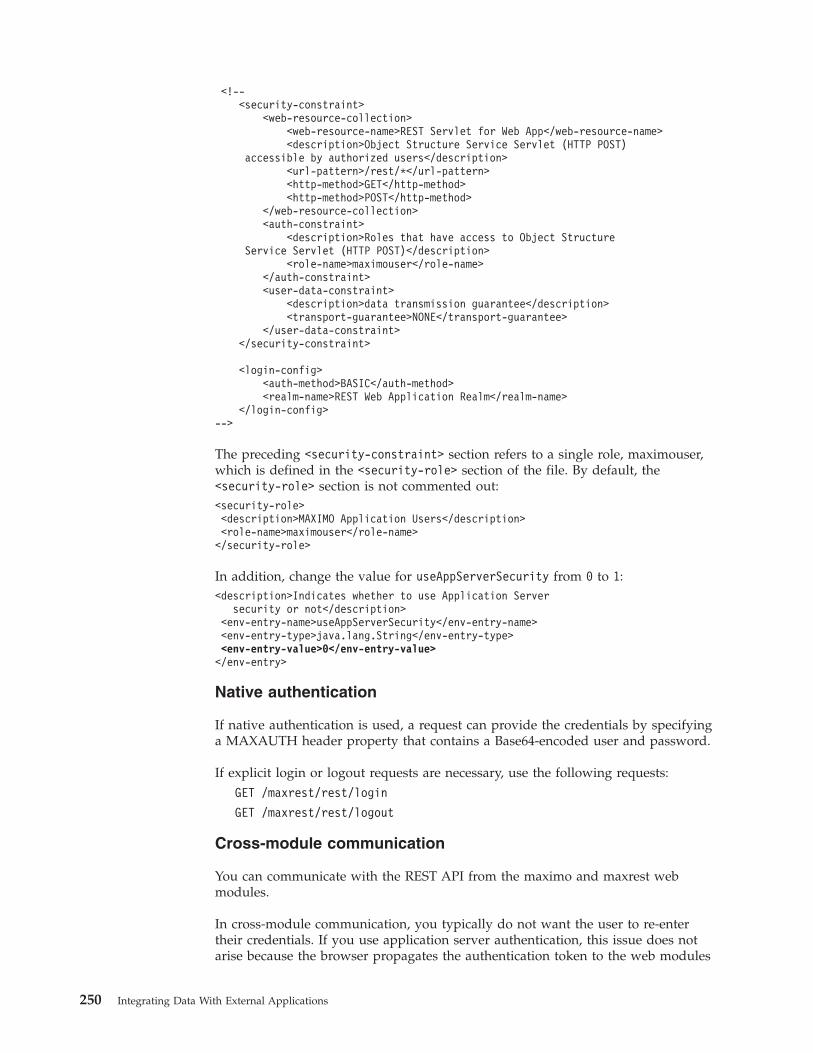
<!--<security-constraint>
<web-resource-collection><web-resource-name>REST Servlet for Web App</web-resource-name><description>Object Structure Service Servlet (HTTP POST)
accessible by authorized users</description><url-pattern>/rest/*</url-pattern><http-method>GET</http-method><http-method>POST</http-method>
</web-resource-collection><auth-constraint>
<description>Roles that have access to Object StructureService Servlet (HTTP POST)</description>
<role-name>maximouser</role-name></auth-constraint><user-data-constraint>
<description>data transmission guarantee</description><transport-guarantee>NONE</transport-guarantee>
</user-data-constraint></security-constraint>
<login-config><auth-method>BASIC</auth-method><realm-name>REST Web Application Realm</realm-name>
</login-config>-->
The preceding <security-constraint> section refers to a single role, maximouser,which is defined in the <security-role> section of the file. By default, the<security-role> section is not commented out:<security-role><description>MAXIMO Application Users</description><role-name>maximouser</role-name></security-role>
In addition, change the value for useAppServerSecurity from 0 to 1:<description>Indicates whether to use Application Server
security or not</description><env-entry-name>useAppServerSecurity</env-entry-name><env-entry-type>java.lang.String</env-entry-type><env-entry-value>0</env-entry-value></env-entry>
Native authentication
If native authentication is used, a request can provide the credentials by specifyinga MAXAUTH header property that contains a Base64-encoded user and password.
If explicit login or logout requests are necessary, use the following requests:GET /maxrest/rest/login
GET /maxrest/rest/logout
Cross-module communication
You can communicate with the REST API from the maximo and maxrest webmodules.
In cross-module communication, you typically do not want the user to re-entertheir credentials. If you use application server authentication, this issue does notarise because the browser propagates the authentication token to the web modules
250 Integrating Data With External Applications
for each request. For native authentication, the REST API is available as a library(commonweb) that any web module can access.
For example, the following URI queries an asset by using the maxrest web module:http://site.example.com:9999/maxrest/rest/mbo/asset/46.
In contrast, the following URI queries an asset by using the user interface webmodule: http://site.example.com:9999/maximo/rest/mbo/asset/46.
Authorization
For object structures, you can connect a resource to an authorizing application onthe Object Structure tab of the Object Structures application. If you specify anauthorizing application, all integration processing that uses the object structure isaffected.
For business objects, you can connect a resource to an authorizing application inthe Application Authorization for Objects window of the Object Structuresapplication. The application authorizes all REST API requests for the specific MBOresource.
You can restrict resource access by specifying a list of resource names in themxe.rest.mbo.blockaccess and mxe.rest.os.blockaccess system properties.Related reference:“REST system properties” on page 256System properties are available to configure how the REST API works for yourspecific requirements.
Customization of the REST APIThe REST API can be customized to support different resource representations,such as the XHTML or Atom formats. It can also be customized by addingattributes to the representation of a business object resource or by changing thestructure of a representation.
To support a new resource representation, you must provide custom serializersthat support the new formats.
If you add attributes, such as an attribute to the work order MBO resource inJSON representation, you must add a custom JSON serializer for the resource. Tosupport additional query parameters, you must extend the MBO or OS handler.
Ensure that your customizations do not affect existing business processes or users.By creating a separate instance of the REST API for the resource types, you canavoid adverse affects.
For any customization, the class files must be included in the application EAR fileas part of the commonweb library.
Example
The following steps customize the REST API:1. Create a system property by copying the mxe.rest.handler.mbo property,
giving the property the name mxe.rest.handler.abcmbo, and assigning it thevalue com.ibm.tivoli.maximo.rest.ABCMboResourceRequestHandler.
Integrating data with external applications 251
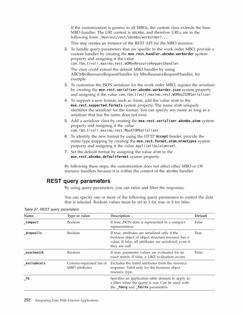
If the customization is generic to all MBOs, the custom class extends the baseMBO handler. The URI context is abcmbo, and therefore URLs are in thefollowing form: /maxrest/rest/abcmbo/workorder?...This step creates an instance of the REST API for the MBO resource.
2. To handle query parameters that are specific to the work order MBO, provide acustom handler by creating the mxe.rest.handler.abcmbo.workorder systemproperty and assigning it the valuecom.ibm.tivoli.maximo.rest.WOMboResourceRequestHandler.The class could extend the default MBO handler by usingABCMboResourceRequestHandler for MboResourceRequestHandler, forexample.
3. To customize the JSON serializer for the work order MBO, register the serializerby creating the mxe.rest.serializer.abcmbo.workorder.json system propertyand assigning it the value com.ibm.tivoli.maximo.rest.WOMboJSONSerializer.
4. To support a new format, such as Atom, add the value atom to themxe.rest.supported.formats system property. The name atom uniquelyidentifies the serializer for the format. You can specify any name as long as aserializer that has the name does not exist.
5. Add a serializer class by creating the mxe.rest.serializer.abcmbo.atom systemproperty and assigning it the valuecom.ibm.tivoli.maximo.rest.MboATOMSerializer.
6. To identify the new format by using the HTTP Accept header, provide themime type mapping by creating the mxe.rest.format.atom.mimetypes systemproperty and assigning it the value application/atom+xml.
7. Set the default format by assigning the value atom to themxe.rest.abcmbo.defaultformat system property.
By following these steps, the customization does not affect other MBO or OSresource handlers because it is within the context of the abcmbo handler.
REST query parametersBy using query parameters, you can tailor and filter the responses.
You can specify one or more of the following query parameters to control the datathat is selected. Boolean values must be set to 1 for true or 0 for false.
Table 37. REST query parameters
Name Type or value Description Default
_compact Boolean If true, JSON data is represented in a compactrepresentation.
False
_dropnulls Boolean If true, attributes are serialized only if thebusiness object or object structure resource has avalue. If false, all attributes are serialized, even ifthey are null.
True
_exactmatch Boolean If true, parameter values are evaluated for anexact match. If false, a LIKE evaluation occurs.
False
_excludecols Comma-separated list ofMBO attributes
Excludes the listed attributes from the resourceresponse. Valid only for the business objectresource type.
_fd Specifies an application table domain to apply asa filter when the query is run. Can be used withthe _fdorg and _fdsite parameters.
252 Integrating Data With External Applications
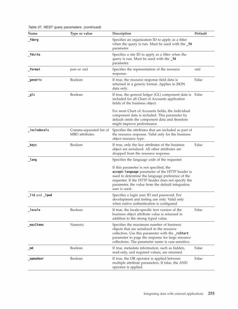
Table 37. REST query parameters (continued)
Name Type or value Description Default
_fdorg Specifies an organization ID to apply as a filterwhen the query is run. Must be used with the _fdparameter.
_fdsite Specifies a site ID to apply as a filter when thequery is run. Must be used with the _fdparameter.
_format json or xml Specifies the representation of the resourceresponse.
xml
_generic Boolean If true, the resource response field data isreturned in a generic format. Applies to JSONdata only.
False
_glc Boolean If true, the general ledger (GL) component data isincluded for all Chart of Accounts applicationfields of the business object.
For most Chart of Accounts fields, the individualcomponent data is included. This parameter bydefault omits the component data and thereforemight improve performance.
False
_includecols Comma-separated list ofMBO attributes
Specifies the attributes that are included as part ofthe resource response. Valid only for the businessobject resource type.
_keys Boolean If true, only the key attributes of the businessobject are serialized. All other attributes aredropped from the resource response.
False
_lang Specifies the language code of the requester.
If this parameter is not specified, theaccept-language parameter of the HTTP header isused to determine the language preference of therequester. If the HTTP header does not specify theparameter, the value from the default integrationuser is used.
_lid and _lpwd Specifies a login user ID and password. Fordevelopment and testing use only. Valid onlywhen native authentication is configured.
_locale Boolean If true, the locale-specific text version of thebusiness object attribute value is returned inaddition to the strong typed value.
False
_maxItems Numeric Specifies the maximum number of businessobjects that are serialized in the resourcecollection. Use this parameter with the _rsStartparameter to page the response for large resourcecollections. The parameter name is case-sensitive.
_md Boolean If true, metadata information, such as hidden,read-only, and required values, are returned.
False
_opmodeor Boolean If true, the OR operator is applied betweenmultiple attribute parameters. If false, the ANDoperator is applied.
False
Integrating data with external applications 253
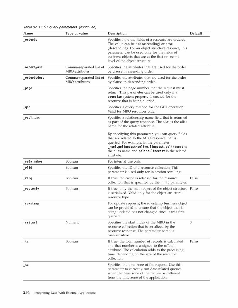
Table 37. REST query parameters (continued)
Name Type or value Description Default
_orderby Specifies how the fields of a resource are ordered.The value can be asc (ascending) or desc(descending). For an object structure resource, thisparameter can be used only for the fields ofbusiness objects that are at the first or secondlevel of the object structure.
_orderbyasc Comma-separated list ofMBO attributes
Specifies the attributes that are used for the orderby clause in ascending order.
_orderbydesc Comma-separated list ofMBO attributes
Specifies the attributes that are used for the orderby clause in descending order.
_page Specifies the page number that the request mustreturn. This parameter can be used only if apagesize system property is created for theresource that is being queried.
_qop Specifies a query method for the GET operation.Valid for MBO resources only.
_rcol.alias Specifies a relationship name field that is returnedas part of the query response. The alias is the aliasname for the related attribute.
By specifying this parameter, you can query fieldsthat are related to the MBO resource that isqueried. For example, in the parameter_rcol.polinecost=poline.linecost, polinecost isthe alias name and poline.linecost is the relatedattribute.
_retainmbos Boolean For internal use only.
_rlid Boolean Specifies the ID of a resource collection. Thisparameter is used only for in-session scrolling.
_rlrq Boolean If true, the cache is released for the resourcecollection that is specified by the _rlid parameter.
False
_rootonly Boolean If true, only the main object of the object structureis serialized. Valid only for the object structureresource type.
False
_rowstamp For update requests, the rowstamp business objectcan be provided to ensure that the object that isbeing updated has not changed since it was firstqueried.
_rsStart Numeric Specifies the start index of the MBO in theresource collection that is serialized by theresource response. The parameter name iscase-sensitive.
0
_tc Boolean If true, the total number of records is calculatedand that number is assigned to the rsTotalattribute. The calculation adds to the processingtime, depending on the size of the resourcecollection.
False
_tz Specifies the time zone of the request. Use thisparameter to correctly run date-related querieswhen the time zone of the request is differentfrom the time zone of the application.
254 Integrating Data With External Applications
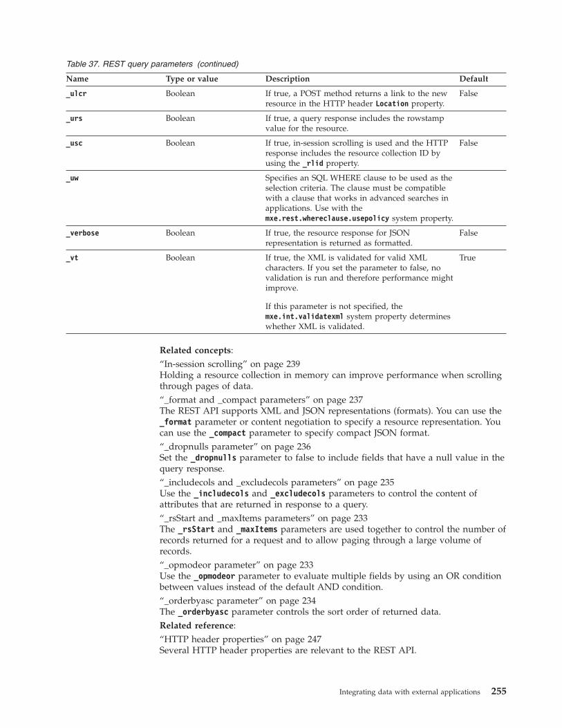
Table 37. REST query parameters (continued)
Name Type or value Description Default
_ulcr Boolean If true, a POST method returns a link to the newresource in the HTTP header Location property.
False
_urs Boolean If true, a query response includes the rowstampvalue for the resource.
_usc Boolean If true, in-session scrolling is used and the HTTPresponse includes the resource collection ID byusing the _rlid property.
False
_uw Specifies an SQL WHERE clause to be used as theselection criteria. The clause must be compatiblewith a clause that works in advanced searches inapplications. Use with themxe.rest.whereclause.usepolicy system property.
_verbose Boolean If true, the resource response for JSONrepresentation is returned as formatted.
False
_vt Boolean If true, the XML is validated for valid XMLcharacters. If you set the parameter to false, novalidation is run and therefore performance mightimprove.
If this parameter is not specified, themxe.int.validatexml system property determineswhether XML is validated.
True
Related concepts:“In-session scrolling” on page 239Holding a resource collection in memory can improve performance when scrollingthrough pages of data.“_format and _compact parameters” on page 237The REST API supports XML and JSON representations (formats). You can use the_format parameter or content negotiation to specify a resource representation. Youcan use the _compact parameter to specify compact JSON format.“_dropnulls parameter” on page 236Set the _dropnulls parameter to false to include fields that have a null value in thequery response.“_includecols and _excludecols parameters” on page 235Use the _includecols and _excludecols parameters to control the content ofattributes that are returned in response to a query.“_rsStart and _maxItems parameters” on page 233The _rsStart and _maxItems parameters are used together to control the number ofrecords returned for a request and to allow paging through a large volume ofrecords.“_opmodeor parameter” on page 233Use the _opmodeor parameter to evaluate multiple fields by using an OR conditionbetween values instead of the default AND condition.“_orderbyasc parameter” on page 234The _orderbyasc parameter controls the sort order of returned data.Related reference:“HTTP header properties” on page 247Several HTTP header properties are relevant to the REST API.
Integrating data with external applications 255
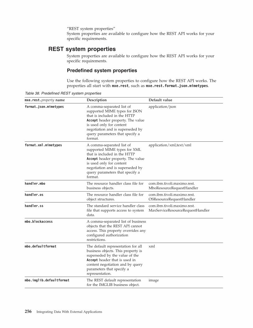
“REST system properties”System properties are available to configure how the REST API works for yourspecific requirements.
REST system propertiesSystem properties are available to configure how the REST API works for yourspecific requirements.
Predefined system properties
Use the following system properties to configure how the REST API works. Theproperties all start with mxe.rest, such as mxe.rest.format.json.mimetypes.
Table 38. Predefined REST system properties
mxe.rest.property name Description Default value
format.json.mimetypes A comma-separated list ofsupported MIME types for JSONthat is included in the HTTPAccept header property. The valueis used only for contentnegotiation and is superseded byquery parameters that specify aformat.
application/json
format.xml.mimetypes A comma-separated list ofsupported MIME types for XMLthat is included in the HTTPAccept header property. The valueis used only for contentnegotiation and is superseded byquery parameters that specify aformat.
application/xml,text/xml
handler.mbo The resource handler class file forbusiness objects.
com.ibm.tivoli.maximo.rest.MboResourceRequestHandler
handler.os The resource handler class file forobject structures.
com.ibm.tivoli.maximo.rest.OSResourceRequestHandler
handler.ss The standard service handler classfile that supports access to systemdata.
com.ibm.tivoli.maximo.rest.MaxServiceResourceRequestHandler
mbo.blockaccess A comma-separated list of businessobjects that the REST API cannotaccess. This property overrides anyconfigured authorizationrestrictions.
mbo.defaultformat The default representation for allbusiness objects. This property issuperseded by the value of theAccept header that is used incontent negotiation and by queryparameters that specify arepresentation.
xml
mbo.imglib.defaultformat The REST default representationfor the IMGLIB business object.
image
256 Integrating Data With External Applications
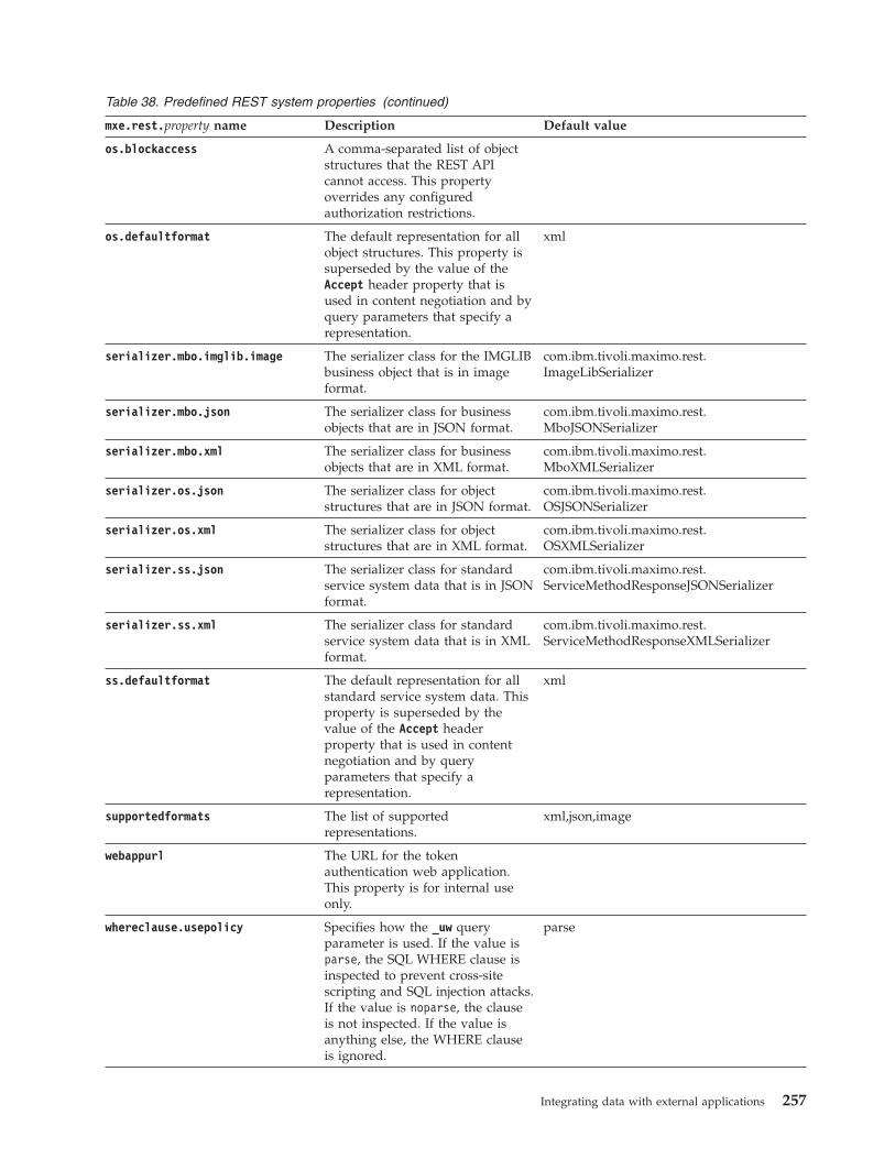
Table 38. Predefined REST system properties (continued)
mxe.rest.property name Description Default value
os.blockaccess A comma-separated list of objectstructures that the REST APIcannot access. This propertyoverrides any configuredauthorization restrictions.
os.defaultformat The default representation for allobject structures. This property issuperseded by the value of theAccept header property that isused in content negotiation and byquery parameters that specify arepresentation.
xml
serializer.mbo.imglib.image The serializer class for the IMGLIBbusiness object that is in imageformat.
com.ibm.tivoli.maximo.rest.ImageLibSerializer
serializer.mbo.json The serializer class for businessobjects that are in JSON format.
com.ibm.tivoli.maximo.rest.MboJSONSerializer
serializer.mbo.xml The serializer class for businessobjects that are in XML format.
com.ibm.tivoli.maximo.rest.MboXMLSerializer
serializer.os.json The serializer class for objectstructures that are in JSON format.
com.ibm.tivoli.maximo.rest.OSJSONSerializer
serializer.os.xml The serializer class for objectstructures that are in XML format.
com.ibm.tivoli.maximo.rest.OSXMLSerializer
serializer.ss.json The serializer class for standardservice system data that is in JSONformat.
com.ibm.tivoli.maximo.rest.ServiceMethodResponseJSONSerializer
serializer.ss.xml The serializer class for standardservice system data that is in XMLformat.
com.ibm.tivoli.maximo.rest.ServiceMethodResponseXMLSerializer
ss.defaultformat The default representation for allstandard service system data. Thisproperty is superseded by thevalue of the Accept headerproperty that is used in contentnegotiation and by queryparameters that specify arepresentation.
xml
supportedformats The list of supportedrepresentations.
xml,json,image
webappurl The URL for the tokenauthentication web application.This property is for internal useonly.
whereclause.usepolicy Specifies how the _uw queryparameter is used. If the value isparse, the SQL WHERE clause isinspected to prevent cross-sitescripting and SQL injection attacks.If the value is noparse, the clauseis not inspected. If the value isanything else, the WHERE clauseis ignored.
parse
Integrating data with external applications 257
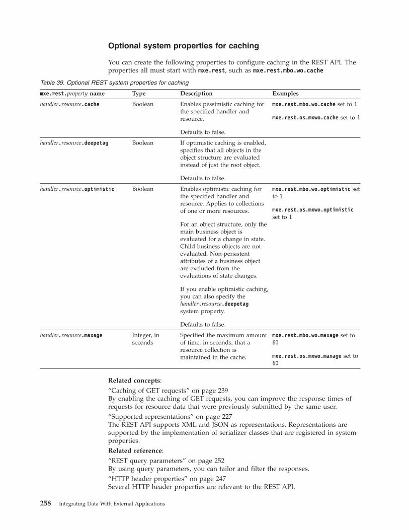
Optional system properties for caching
You can create the following properties to configure caching in the REST API. Theproperties all must start with mxe.rest, such as mxe.rest.mbo.wo.cache
Table 39. Optional REST system properties for caching
mxe.rest.property name Type Description Examples
handler.resource.cache Boolean Enables pessimistic caching forthe specified handler andresource.
Defaults to false.
mxe.rest.mbo.wo.cache set to 1
mxe.rest.os.mxwo.cache set to 1
handler.resource.deepetag Boolean If optimistic caching is enabled,specifies that all objects in theobject structure are evaluatedinstead of just the root object.
Defaults to false.
handler.resource.optimistic Boolean Enables optimistic caching forthe specified handler andresource. Applies to collectionsof one or more resources.
For an object structure, only themain business object isevaluated for a change in state.Child business objects are notevaluated. Non-persistentattributes of a business objectare excluded from theevaluations of state changes.
If you enable optimistic caching,you can also specify thehandler.resource.deepetagsystem property.
Defaults to false.
mxe.rest.mbo.wo.optimistic setto 1
mxe.rest.os.mxwo.optimisticset to 1
handler.resource.maxage Integer, inseconds
Specified the maximum amountof time, in seconds, that aresource collection ismaintained in the cache.
mxe.rest.mbo.wo.maxage set to60
mxe.rest.os.mxwo.maxage set to60
Related concepts:“Caching of GET requests” on page 239By enabling the caching of GET requests, you can improve the response times ofrequests for resource data that were previously submitted by the same user.“Supported representations” on page 227The REST API supports XML and JSON as representations. Representations aresupported by the implementation of serializer classes that are registered in systemproperties.Related reference:“REST query parameters” on page 252By using query parameters, you can tailor and filter the responses.“HTTP header properties” on page 247Several HTTP header properties are relevant to the REST API.
258 Integrating Data With External Applications
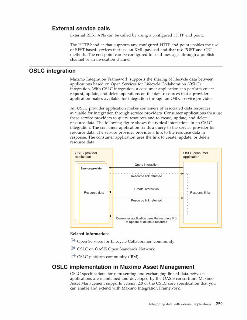
External service callsExternal REST APIs can be called by using a configured HTTP end point.
The HTTP handler that supports any configured HTTP end point enables the useof REST-based services that use an XML payload and that use POST and GETmethods. The end point can be configured to send messages through a publishchannel or an invocation channel.
OSLC integrationMaximo Integration Framework supports the sharing of lifecycle data betweenapplications based on Open Services for Lifecycle Collaboration (OSLC)integration. With OSLC integration, a consumer application can perform create,request, update, and delete operations on the data resources that a providerapplication makes available for integration through an OSLC service provider.
An OSLC provider application makes containers of associated data resourcesavailable for integration through service providers. Consumer applications then usethese service providers to query resources and to create, update, and deleteresource data. The following figure shows the typical interactions in an OSLCintegration. The consumer application sends a query to the service provider forresource data. The service provider provides a link to the resource data inresponse. The consumer application uses the link to create, update, or deleteresource data.
Service provider
OSLC providerapplication
Query interaction
Resource links
OSLC consumerapplication
Create interaction
Resource link returned
Consumer application uses the resource linkto update or delete a resource
Resource link returned
Resource data
Related information:
Open Services for Lifecycle Collaboration community
OSLC on OASIS Open Standards Network
OSLC platform community (IBM)
OSLC implementation in Maximo Asset ManagementOSLC specifications for representing and exchanging linked data betweenapplications are maintained and developed by the OASIS consortium. MaximoAsset Management supports version 2.0 of the OSLC core specification that youcan enable and extend with Maximo Integration Framework.
Integrating data with external applications 259
OSLC specifications define how lifecycle applications represent, link to, and accessresources based on established internet and linked-data standards includingrepresentational state transfer (REST) architecture, resource description framework(RDF) specifications, and hyper-text transfer protocol (HTTP) methods.Specifications are designed to be minimal in nature to address common integrationuse cases and integrators can extend these specifications or add new ones toaddress specific integration scenarios.
Maximo Asset Management is configured as an OSLC provider with the followingcomponents:v In the OSLC Resources application, you configure the data resources for
integration. Each OSLC resource is based on an object structure that specifies theprimary business object and any associated child business objects that can beintegrated.
v OSLC resources are generated as shape documents that describe the resourceobjects in RDF/XML format. A shape document indicates what are the requiredcharacteristics of a resource and can also describe many aspects of the resourceobject, including its dependencies, attributes, and properties. A resource shapedocument can include links to the shape documents for any child objects of theresource.
v Resources are grouped by functional domain. Functional groupings can be basedon the existing domain specifications that are developed and maintained by theOASIS OSLC group. Integrators can extend these existing domain specificationsor create additional domain specifications to support business requirements.
v The resources in a domain are made available to OSLC consumers throughservice providers.
v A single service provider is supported for each domain. Service providerssupport the OSLC creation factory and query capability operations that provideOSLC consumers with the URI to create or search supported resources.
v The security framework supports authentication and authorization for OSLCservices. Maximo Asset Management native authentication and J2EEauthentication are supported. Authorization control is provided by the objectstructure for a resource and application-level and user-based authorization areapplied.
An OSLC consumer uses the following HTTP methods and header information tointeract with the OSLC provider:v Sends a GET request to perform login if explicit login is required and includes
an authorization property in the HTTP header if native authentication is used. Ifexplicit logout is required, a GET request is also used.
v Sends GET requests that include OSLC query parameters to a service providerURI to query OSLC resources.
v Sends a POST request to create an instance of an OSLC resource. The requestincludes a JSON document that conforms to the published shape document forthe OSLC resource. When the resource instance is created, the OSLC providersends a HTTP response that includes the URI for the new resource.
v Sends a PUT or PATCH request to update an OSLC resource. A PUT requestupdates the entire resource. A PATCH request updates part of the resource.
v Uses entity tags (ETags) in HTTP headers to ensure that a resource entity iscurrent and can combine ETags with If-Match headers in PUT and PATCHrequests to enable conditional updates.
v Can request stable paging in GET requests for collection resources so that theresponse redirects the consumer application to a URI where multiple pages are
260 Integrating Data With External Applications
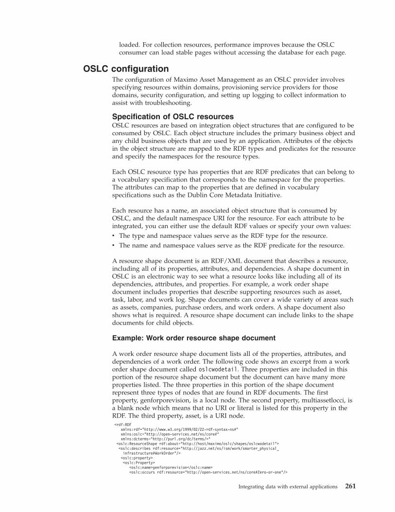
loaded. For collection resources, performance improves because the OSLCconsumer can load stable pages without accessing the database for each page.
OSLC configurationThe configuration of Maximo Asset Management as an OSLC provider involvesspecifying resources within domains, provisioning service providers for thosedomains, security configuration, and setting up logging to collect information toassist with troubleshooting.
Specification of OSLC resourcesOSLC resources are based on integration object structures that are configured to beconsumed by OSLC. Each object structure includes the primary business object andany child business objects that are used by an application. Attributes of the objectsin the object structure are mapped to the RDF types and predicates for the resourceand specify the namespaces for the resource types.
Each OSLC resource type has properties that are RDF predicates that can belong toa vocabulary specification that corresponds to the namespace for the properties.The attributes can map to the properties that are defined in vocabularyspecifications such as the Dublin Core Metadata Initiative.
Each resource has a name, an associated object structure that is consumed byOSLC, and the default namespace URI for the resource. For each attribute to beintegrated, you can either use the default RDF values or specify your own values:v The type and namespace values serve as the RDF type for the resource.v The name and namespace values serve as the RDF predicate for the resource.
A resource shape document is an RDF/XML document that describes a resource,including all of its properties, attributes, and dependencies. A shape document inOSLC is an electronic way to see what a resource looks like including all of itsdependencies, attributes, and properties. For example, a work order shapedocument includes properties that describe supporting resources such as asset,task, labor, and work log. Shape documents can cover a wide variety of areas suchas assets, companies, purchase orders, and work orders. A shape document alsoshows what is required. A resource shape document can include links to the shapedocuments for child objects.
Example: Work order resource shape document
A work order resource shape document lists all of the properties, attributes, anddependencies of a work order. The following code shows an excerpt from a workorder shape document called oslcwodetail. Three properties are included in thisportion of the resource shape document but the document can have many moreproperties listed. The three properties in this portion of the shape documentrepresent three types of nodes that are found in RDF documents. The firstproperty, genforporevision, is a local node. The second property, multiassetlocci, isa blank node which means that no URI or literal is listed for this property in theRDF. The third property, asset, is a URI node.<rdf:RDF
xmlns:rdf="http://www.w3.org/1999/02/22-rdf-syntax-ns#"xmlns:oslc="http://open-services.net/ns/core#"xmlns:dcterms="http://purl.org/dc/terms/>"
<oslc:ResourceShape rdf:about="http://host/maximo/oslc/shapes/oslcwodetail"><oslc:describes rdf:resource="http://jazz.net/ns/ism/work/smarter_physical_
infrastructure#WorkOrder"/><oslc:property><oslc:Property>
<oslc:name>genforporevision</oslc:name><oslc:occurs rdf:resource="http://open-services.net/ns/core#Zero-or-one"/>
Integrating data with external applications 261
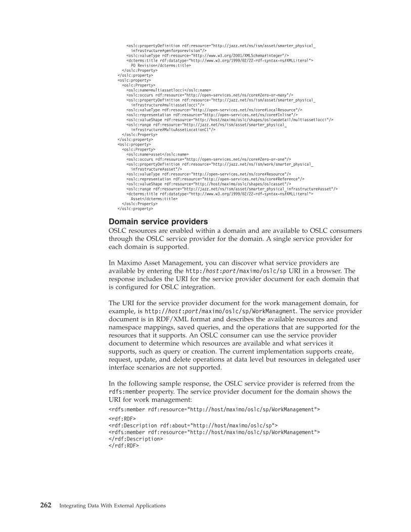
<oslc:propertyDefinition rdf:resource="http://jazz.net/ns/ism/asset/smarter_physical_infrastructure#genforporevision"/>
<oslc:valueType rdf:resource="http://www.w3.org/2001/XMLSchema#integer"/><dcterms:title rdf:datatype="http://www.w3.org/1999/02/22-rdf-syntax-ns#XMLLiteral">
PO Revision</dcterms:title></oslc:Property>
</oslc:property><oslc:property>
<oslc:Property><oslc:name>multiassetlocci</oslc:name><oslc:occurs rdf:resource="http://open-services.net/ns/core#Zero-or-many"/><oslc:propertyDefinition rdf:resource="http://jazz.net/ns/ism/asset/smarter_physical_
infrastructure#multiassetlocci"/><oslc:valueType rdf:resource="http://open-services.net/ns/core#LocalResource"/><oslc:representation rdf:resource="http://open-services.net/ns/core#Inline"/><oslc:valueShape rdf:resource="http://host/maximo/oslc/shapes/oslcwodetail/multiassetlocci"/><oslc:range rdf:resource="http://jazz.net/ns/ism/asset/smarter_physical_
infrastructure#MultuAssetLocationCI"/></oslc:Property>
</oslc:property><oslc:property>
<oslc:Property><oslc:name>asset</oslc:name><oslc:occurs rdf:resource="http://open-services.net/ns/core#Zero-or-one"/><oslc:propertyDefinition rdf:resource="http://jazz.net/ns/ism/work/smarter_physical_
infrastructure#asset"/><oslc:valueType rdf:resource="http://open-services.net/ns/core#Resource"/><oslc:representation rdf:resource="http://open-services.net/ns/core#Reference"/><oslc:valueShape rdf:resource="http://host/maximo/oslc/shapes/oslcasset"/><oslc:range rdf:resource="http://jazz.net/ns/ism/asset/smarter_physical_infrastructure#asset"/><dcterms:title rdf:datatype="http://www.w3.org/1999/02/22-rdf-syntax-ns#XMLLiteral">
Asset</dcterms:title></oslc:Property>
</oslc:property>
Domain service providersOSLC resources are enabled within a domain and are available to OSLC consumersthrough the OSLC service provider for the domain. A single service provider foreach domain is supported.
In Maximo Asset Management, you can discover what service providers areavailable by entering the http:/host:port/maximo/oslc/sp URI in a browser. Theresponse includes the URI for the service provider document for each domain thatis configured for OSLC integration.
The URI for the service provider document for the work management domain, forexample, is http://host:port/maximo/oslc/sp/WorkManagment. The service providerdocument is in RDF/XML format and describes the available resources andnamespace mappings, saved queries, and the operations that are supported for theresources that it supports. An OSLC consumer can use the service providerdocument to determine which resources are available and what services itsupports, such as query or creation. The current implementation supports create,request, update, and delete operations at data level but resources in delegated userinterface scenarios are not supported.
In the following sample response, the OSLC service provider is referred from therdfs:member property. The service provider document for the domain shows theURI for work management:<rdfs:member rdf:resource="http://host/maximo/oslc/sp/WorkManagement">
<rdf:RDF><rdf:Description rdf:about="http://host/maximo/oslc/sp"><rdfs:member rdf:resource="http://host/maximo/oslc/sp/WorkManagement"></rdf:Description></rdf:RDF>
262 Integrating Data With External Applications
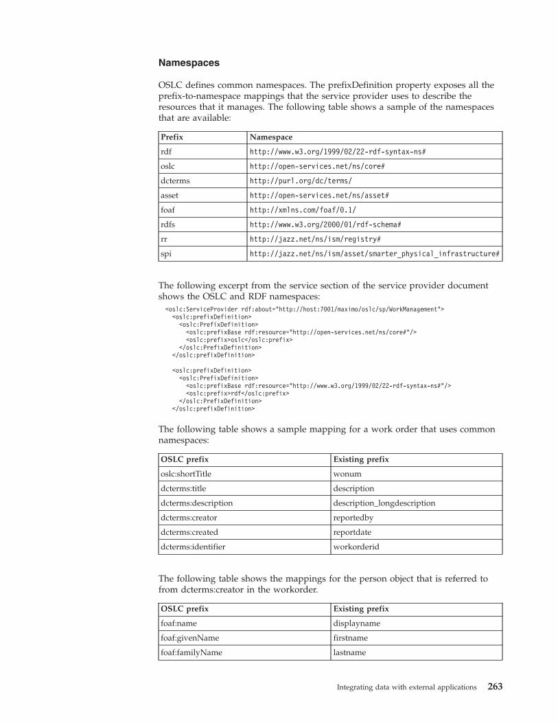
Namespaces
OSLC defines common namespaces. The prefixDefinition property exposes all theprefix-to-namespace mappings that the service provider uses to describe theresources that it manages. The following table shows a sample of the namespacesthat are available:
Prefix Namespace
rdf http://www.w3.org/1999/02/22-rdf-syntax-ns#
oslc http://open-services.net/ns/core#
dcterms http://purl.org/dc/terms/
asset http://open-services.net/ns/asset#
foaf http://xmlns.com/foaf/0.1/
rdfs http://www.w3.org/2000/01/rdf-schema#
rr http://jazz.net/ns/ism/registry#
spi http://jazz.net/ns/ism/asset/smarter_physical_infrastructure#
The following excerpt from the service section of the service provider documentshows the OSLC and RDF namespaces:<oslc:ServiceProvider rdf:about="http://host:7001/maximo/oslc/sp/WorkManagement"><oslc:prefixDefinition><oslc:PrefixDefinition><oslc:prefixBase rdf:resource="http://open-services.net/ns/core#"/><oslc:prefix>oslc</oslc:prefix>
</oslc:PrefixDefinition></oslc:prefixDefinition>
<oslc:prefixDefinition><oslc:PrefixDefinition><oslc:prefixBase rdf:resource="http://www.w3.org/1999/02/22-rdf-syntax-ns#"/><oslc:prefix>rdf</oslc:prefix>
</oslc:PrefixDefinition></oslc:prefixDefinition>
The following table shows a sample mapping for a work order that uses commonnamespaces:
OSLC prefix Existing prefix
oslc:shortTitle wonum
dcterms:title description
dcterms:description description_longdescription
dcterms:creator reportedby
dcterms:created reportdate
dcterms:identifier workorderid
The following table shows the mappings for the person object that is referred tofrom dcterms:creator in the workorder.
OSLC prefix Existing prefix
foaf:name displayname
foaf:givenName firstname
foaf:familyName lastname
Integrating data with external applications 263
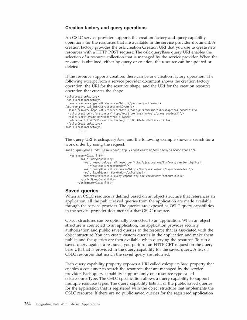
Creation factory and query operations
An OSLC service provider supports the creation factory and query capabilityoperations for the resources that are available in the service provider document. Acreation factory provides the oslc:creation Creation URI that you use to create newresources with a HTTP POST request. The oslc:queryBase query URI enables theselection of a resource collection that is managed by the service provider. When theresource is obtained, either by query or creation, the resource can be updated ordeleted.
If the resource supports creation, there can be one creation factory operation. Thefollowing excerpt from a service provider document shows the creation factoryoperation, the URI for the resource shape, and the URI for the creation resourceoperation that creates the shape.<oslc:creationFactory><oslc:CreationFactory><oslc:resourceType rdf:resource="http://jazz.net/ns/ism/work
/smarter_physical_infrastructure#WorkOrder"/><oslc:resourceShape rdf:resource="http://host:port/maximo/oslc/shapes/oslcwodetail"/><oslc:creation rdf:resource="http://host:port/maximo/oslc/os/oslcwodetail"/><oslc:label>Create WorkOrder</oslc:label><dcterms:title>OSLC creation factory for WorkOrder</dcterms:title>
</oslc:CreationFactory></oslc:creationFactory>
......
The query URI is oslc:queryBase, and the following example shows a search for awork order by using the request:<oslc:queryBase rdf:resource="http://host/maximo/oslc/os/oslcwodetail"/>
<oslc:queryCapability><oslc:QueryCapability><oslc:resourceType rdf:resource="http://jazz.net/ns/ism/work/smarter_physical_
infrastructure#WorkOrder"/><oslc:queryBase rdf:resource="http://host/maximo/oslc/os/oslcwodetail"/><oslc:labelQuery> WorkOrder</oslc:label><dcterms:title>OSLC query capability for WorkOrder</dcterms:title>
</oslc:QueryCapability></oslc:queryCapability>
Saved queriesWhen an OSLC resource is defined based on an object structure that references anapplication, all the public saved queries from the application are made availablethrough the service provider. The queries are exposed as OSLC query capabilitiesin the service provider document for that OSLC resource.
Object structures can be optionally connected to an application. When an objectstructure is connected to an application, the application provides securityauthorization and public saved queries to the resource that is associated with theobject structure. You can create custom queries in the application and make thempublic, and the queries are then available when querying the resource. To run asaved query against a resource, you perform an HTTP GET request on the querybase URI that is provided in the query capability for the saved query. A list ofOSLC resources that match the saved query are returned.
Each query capability property exposes a URI called oslc:queryBase property thatenables a consumer to search the resources that are managed by the serviceprovider. Each query capability supports only one resource type calledoslc:resourceType. The OSLC specification allows a query capability to supportmultiple resource types. The query capability lists all of the public saved queriesfor the application that is registered with the object structure that implements theOSLC resource. If there are no public saved queries for the registered application
264 Integrating Data With External Applications
or if no application was registered, only one query capability provides the genericquery collection URI. There is always at least one query capability for eachresource type that is supported by the service provider.
Example: Saved queries in the Work order application
You create a query in the Work Order application to search for work orders thatyou own. You make the query public so that the query appears in the serviceprovider document as savedQuery=OWNER+IS+ME. TheOSLC top-level object structuremust also be work order.<oslc:service>
<oslc:Service><oslc:queryCapability><oslc:QueryCapability><oslc:resourceType rdf:resource="http://jazz.net/ns/ism/work/smarter_physical_
infrastructure#WorkOrder"/><oslc:queryBase rdf:resource="http://host/maximo/oslc/os/oslcwodetail?
savedQuery=OWNER+IS+ME"/><oslc:label>Query OWNER IS ME</oslc:label><dcterms:title>OSLC query capability for My Work Orders</dcterms:title>
</oslc:QueryCapability></oslc:queryCapability><oslc:queryCapability><oslc:QueryCapability><oslc:resourceType rdf:resource="http://jazz.net/ns/ism/work/smarter_physical_
infrastructure#WorkOrder"/><oslc:queryBase rdf:resource="http://host/maximo/oslc/os/oslcwodetail"/><oslc:label>Query WorkOrder</oslc:label><dcterms:title>OSLC query capability for WorkOrder</dcterms:title>
</oslc:QueryCapability></oslc:queryCapability>......
OSLC securityAuthentication and authorization support for OSLC services is provided by theMaximo Asset Managementsecurity framework. J2EE-based authentication such asLDAP is supported through the application server. The application server alsoprovides support for HTTPS.
Native authentication to Maximo Asset Management
The consumer request can provide the user:password values that are base64 encodedand are in the MAXAUTH HTTP header property.
J2EE authentication
To configure J2EE authentication, you modify the web.xml file, set securityconstraints and set the useAppServerSecurity property to true.
You modify the web.xml file for the maximouiweb web module by uncommentingthe following lines:<!--<servlet><display-name>OSLC Servlet for Web App</display-name><servlet-name>OSLCServlet</servlet-name><servlet-class>
com.ibm.tivoli.maximo.oslc.provider.MaximoOslcProviderServlet</servlet-class><init-param><param-name>char_encoding</param-name><param-value>UTF-8</param-value></init-param></servlet>-->
Integrating data with external applications 265
<!--servlet-mapping><servlet-name>OSLCServlet</servlet-name><url-pattern>/oslc/*</url-pattern></servlet-mapping
To configure security constraints, you enter the following code for<web-resource-collection>:<web-resource-collection><web-resource-name>OSLC Servlet</web-resource-name><description>
OSLC Object Structure Servlet accessible by authorized users</description><url-pattern>/oslc/*</url-pattern><http-method>GET</http-method><http-method>POST</http-method><http-method>PUT</http-method><http-method>HEAD</http-method></web-resource-collection>
The useAppServerSecurity property must be set to true:<env-entry><description>
Indicates whether to use Application Server security or not</description><env-entry-nameuseAppServerSecurity</env-entry-name><env-entry-typejava.lang.String</env-entry-type><env-entry-valuefalse</env-entry-value></env-entry>
Explicit login and logout
If the consumer application needs to run explicit login commands, you use thefollowing request:GET /maximo/oslc/login
If you are using native authentication, you must add the MAXAUTH HTTP headerproperty to the login request. If the consumer application needs to run explicitlogout commands, you use the following request:GET /maximo/oslc/logout
Authorization
Authorization control is provided at the object structure level of the resource. Youassociate the object structure to an application in the Object Structure application.The security processing of the resource data is then based on both theconfiguration of security of the application and the user group of the user whomade the HTTP request. When OSLC resources are processed, any object attributethat is configured as hidden through security is not included in the response to anOSLC request.
OSLC loggingLog correlation can record information when OSLC resources are created orupdated. The information that is logged includes the total response time and thesize of the resource in bytes. The information can be used for performanceanalysis. For example, you can use the log information to analyze response times.
266 Integrating Data With External Applications
To enable log correlation so that information is recorded during GET, POST andPUT requests, go to System configuration > Platform configuration > Systemproperties application and ensure that the mxe.logging.CorrelationEnabledproperty is set to 1.
The following table shows some of the information that might be logged when youenable the mxe.logging.CorrelationEnabled property. Some of the attributes in thetable might not be available for every request.
Attribute Description
ClientIP IP address of the client that makes the request of the serverthrough OSLC.
InvokeAndSerTime Time that is taken for invocation and serialization.
SendResponseTime Time that is required for the server to respond to a clientrequest.
RequestURI Universal resource identifier of the client.
RequestParams Parameters that are passed in the URI of the client.
ElapsedTime Total time that is required from client request to serverresponse.
LoginID User name that is associated with a client authenticationrequest.
ResourceSize Size of the resource in bytes.
EndUserClientIP IP address of the end user who makes the request of theserver.
EndUserMetaData Data that is associated with the actual end client user.Requests are often delivered through an intermediary server.This attribute, when present, always contains end user data.
ClientPort Port number that the client uses to make a request of theserver.
HTTP transactionsInteractions between OSLC consumer and the OSLC resources provided byMaximo Asset Management use standard HTTP requests and responses. SupportedHTTP request methods include GET, POST, PUT, and PATCH. HTTP responsesprovide information in HTTP headers and HTTP error codes are returned whenrequests are not successful.
OSLC resource queriesOSLC defines a lightweight query syntax that is based on SPARQL standard toquery resources. The OSLC query parameter that is set in a HTTP GET requestdetermines the type of information that the service provider sends in response.
Query properties parameter:
The oslc.properties query parameter returns a list of properties for an OSLCresource and provides a partial representation of the resource.
The oslc.properties parameter is applicable only when you are retrieving a singleresource based on a resource ID. Other query parameters apply when you want toquery a resource collection which contains zero or more instances of a resource.
Integrating data with external applications 267
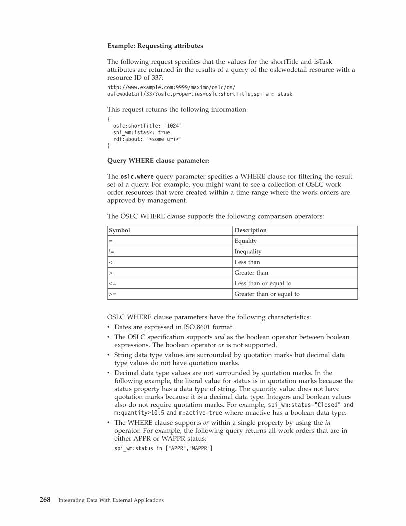
Example: Requesting attributes
The following request specifies that the values for the shortTitle and isTaskattributes are returned in the results of a query of the oslcwodetail resource with aresource ID of 337:http://www.example.com:9999/maximo/oslc/os/oslcwodetail/337?oslc.properties=oslc:shortTitle,spi_wm:istask
This request returns the following information:{
oslc:shortTitle: "1024"spi_wm:istask: truerdf:about: "<some uri>"
}
Query WHERE clause parameter:
The oslc.where query parameter specifies a WHERE clause for filtering the resultset of a query. For example, you might want to see a collection of OSLC workorder resources that were created within a time range where the work orders areapproved by management.
The OSLC WHERE clause supports the following comparison operators:
Symbol Description
= Equality
!= Inequality
< Less than
> Greater than
<= Less than or equal to
>= Greater than or equal to
OSLC WHERE clause parameters have the following characteristics:v Dates are expressed in ISO 8601 format.v The OSLC specification supports and as the boolean operator between boolean
expressions. The boolean operator or is not supported.v String data type values are surrounded by quotation marks but decimal data
type values do not have quotation marks.v Decimal data type values are not surrounded by quotation marks. In the
following example, the literal value for status is in quotation marks because thestatus property has a data type of string. The quantity value does not havequotation marks because it is a decimal data type. Integers and boolean valuesalso do not require quotation marks. For example, spi_wm:status="Closed" andm:quantity>10.5 and m:active=true where m:active has a boolean data type.
v The WHERE clause supports or within a single property by using the inoperator. For example, the following query returns all work orders that are ineither APPR or WAPPR status:spi_wm:status in ["APPR","WAPPR"]
268 Integrating Data With External Applications
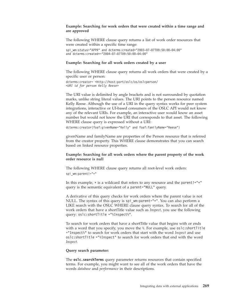
Example: Searching for work orders that were created within a time range andare approved
The following WHERE clause query returns a list of work order resources thatwere created within a specific time range:spi_wm:status="APPR" and dcterms:created>"2003-07-07T09:50:00-04:00"and dcterms:created<="2004-07-07T09:50:00-04:00"
Example: Searching for all work orders created by a user
The following WHERE clause query returns all work orders that were created by aspecific user or person:dcterms:creator= <http://host:port/oslc/os/oslcperson/<URI id for person Kelly Reese>
The URI value is delimited by angle brackets and is not surrounded by quotationmarks, unlike string literal values. The URI points to the person resource namedKelly Reese. Although the use of a URI in the query syntax works for peer systemintegrations, interactive or UI-based consumers of the OSLC API would not knowany of the relevant URIs. For example, an interactive user would know an assetnumber but would not know the URI that corresponds to that asset. The followingWHERE clause query is expressed without a URI:dcterms:creator{foaf:givenName=”Kelly” and foaf:familyName=”Reese”}
givenName and familyName are properties of the Person resource that is referredfrom the creator property. This WHERE clause demonstrates that you can searchbased on linked resource properties.
Example: Searching for all work orders where the parent property of the workorder resource is null
The following WHERE clause query returns all root-level work orders:spi_wm:parent!=”*”
In this example, * is a wildcard that refers to any resource and the parent!="*"query is the semantic equivalent of a parent="NULL" query.
A derivative of this query checks for work orders where the parent value is notNULL. The syntax of this query is spi_wm:parent=”*”. You can also perform aLIKE search with the OSLC WHERE clause query syntax. To search for all of thework orders that have a shortTitle value such as Inspect, you use the followingquery: oslc:shortTitle =”%Inspect%”.
To search for work orders that have a shortTitle value that begins with or endswith a word that you specify, you move the %. For example, use oslc:shortTitle=”Inspect%” to search for work orders that start with the word Inspect and useoslc:shortTitle =”%Inspect” to search for work orders that end with the wordInspect.
Query search parameter:
The oslc.searchTerms query parameter returns resources that contain specifiedterms. For example, you might want to see all of the work orders that have thewords database and performance in their descriptions.
Integrating data with external applications 269
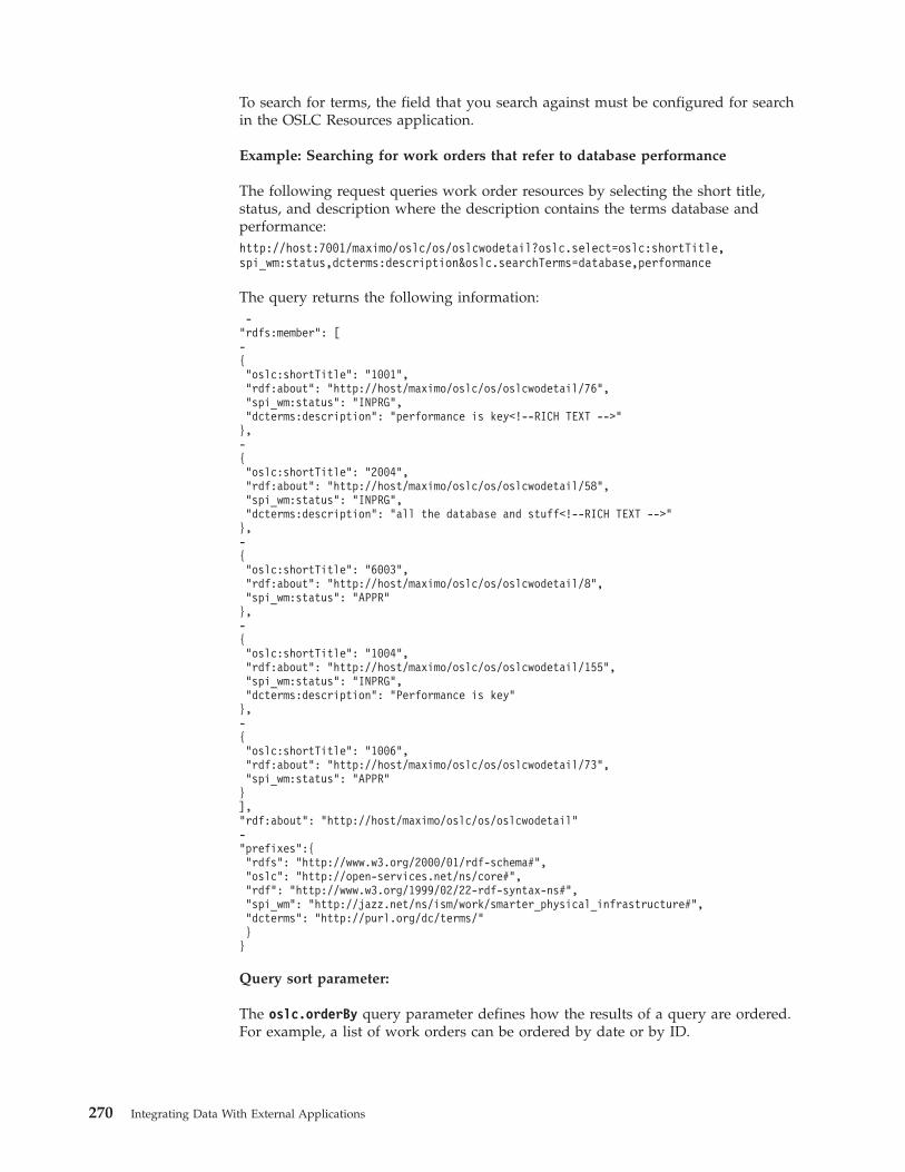
To search for terms, the field that you search against must be configured for searchin the OSLC Resources application.
Example: Searching for work orders that refer to database performance
The following request queries work order resources by selecting the short title,status, and description where the description contains the terms database andperformance:http://host:7001/maximo/oslc/os/oslcwodetail?oslc.select=oslc:shortTitle,spi_wm:status,dcterms:description&oslc.searchTerms=database,performance
The query returns the following information:-"rdfs:member": [-{"oslc:shortTitle": "1001","rdf:about": "http://host/maximo/oslc/os/oslcwodetail/76","spi_wm:status": "INPRG","dcterms:description": "performance is key<!--RICH TEXT -->"},-{"oslc:shortTitle": "2004","rdf:about": "http://host/maximo/oslc/os/oslcwodetail/58","spi_wm:status": "INPRG","dcterms:description": "all the database and stuff<!--RICH TEXT -->"},-{"oslc:shortTitle": "6003","rdf:about": "http://host/maximo/oslc/os/oslcwodetail/8","spi_wm:status": "APPR"},-{"oslc:shortTitle": "1004","rdf:about": "http://host/maximo/oslc/os/oslcwodetail/155","spi_wm:status": "INPRG","dcterms:description": "Performance is key"},-{"oslc:shortTitle": "1006","rdf:about": "http://host/maximo/oslc/os/oslcwodetail/73","spi_wm:status": "APPR"}],"rdf:about": "http://host/maximo/oslc/os/oslcwodetail"-"prefixes":{"rdfs": "http://www.w3.org/2000/01/rdf-schema#","oslc": "http://open-services.net/ns/core#","rdf": "http://www.w3.org/1999/02/22-rdf-syntax-ns#","spi_wm": "http://jazz.net/ns/ism/work/smarter_physical_infrastructure#","dcterms": "http://purl.org/dc/terms/"}}
Query sort parameter:
The oslc.orderBy query parameter defines how the results of a query are ordered.For example, a list of work orders can be ordered by date or by ID.
270 Integrating Data With External Applications
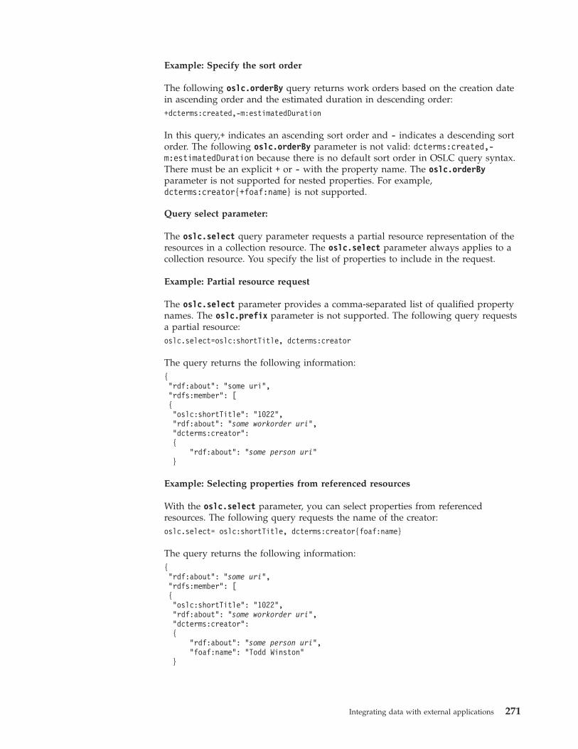
Example: Specify the sort order
The following oslc.orderBy query returns work orders based on the creation datein ascending order and the estimated duration in descending order:+dcterms:created,-m:estimatedDuration
In this query,+ indicates an ascending sort order and - indicates a descending sortorder. The following oslc.orderBy parameter is not valid: dcterms:created,-m:estimatedDuration because there is no default sort order in OSLC query syntax.There must be an explicit + or - with the property name. The oslc.orderByparameter is not supported for nested properties. For example,dcterms:creator{+foaf:name} is not supported.
Query select parameter:
The oslc.select query parameter requests a partial resource representation of theresources in a collection resource. The oslc.select parameter always applies to acollection resource. You specify the list of properties to include in the request.
Example: Partial resource request
The oslc.select parameter provides a comma-separated list of qualified propertynames. The oslc.prefix parameter is not supported. The following query requestsa partial resource:oslc.select=oslc:shortTitle, dcterms:creator
The query returns the following information:{"rdf:about": "some uri","rdfs:member": [{"oslc:shortTitle": "1022","rdf:about": "some workorder uri","dcterms:creator":{
"rdf:about": "some person uri"}
Example: Selecting properties from referenced resources
With the oslc.select parameter, you can select properties from referencedresources. The following query requests the name of the creator:oslc.select= oslc:shortTitle, dcterms:creator{foaf:name}
The query returns the following information:{"rdf:about": "some uri","rdfs:member": [{"oslc:shortTitle": "1022","rdf:about": "some workorder uri","dcterms:creator":{
"rdf:about": "some person uri","foaf:name": "Todd Winston"
}
Integrating data with external applications 271
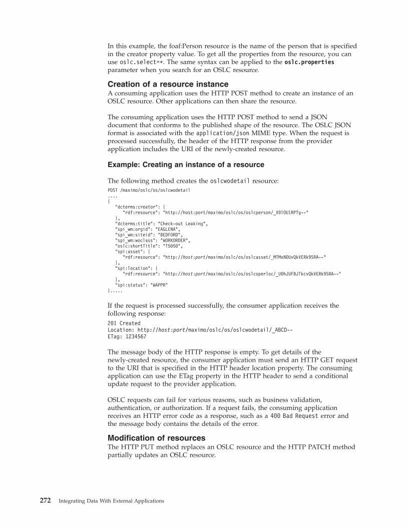
In this example, the foaf:Person resource is the name of the person that is specifiedin the creator property value. To get all the properties from the resource, you canuse oslc.select=*. The same syntax can be applied to the oslc.propertiesparameter when you search for an OSLC resource.
Creation of a resource instanceA consuming application uses the HTTP POST method to create an instance of anOSLC resource. Other applications can then share the resource.
The consuming application uses the HTTP POST method to send a JSONdocument that conforms to the published shape of the resource. The OSLC JSONformat is associated with the application/json MIME type. When the request isprocessed successfully, the header of the HTTP response from the providerapplication includes the URI of the newly-created resource.
Example: Creating an instance of a resource
The following method creates the oslcwodetail resource:POST /maximo/oslc/os/oslcwodetail....{
"dcterms:creator": {"rdf:resource": "http://host:port/maximo/oslc/os/oslcperson/_V0lOU1RPTg--"
},"dcterms:title": "Check-out Leaking","spi_wm:orgid": "EAGLENA","spi_wm:siteid": "BEDFORD","spi_wm:woclass": "WORKORDER","oslc:shortTitle": "T5050","spi:asset": {
"rdf:resource": "http://host:port/maximo/oslc/os/oslcasset/_MTMxNDUvQkVERk9SRA--"},"spi:location": {
"rdf:resource": "http://host:port/maximo/oslc/os/oslcoperloc/_U0hJUFBJTkcvQkVERk9SRA--"},"spi:status": "WAPPR"
}.....
If the request is processed successfully, the consumer application receives thefollowing response:201 CreatedLocation: http://host:port/maximo/oslc/os/oslcwodetail/_ABCD--ETag: 1234567
The message body of the HTTP response is empty. To get details of thenewly-created resource, the consumer application must send an HTTP GET requestto the URI that is specified in the HTTP header location property. The consumingapplication can use the ETag property in the HTTP header to send a conditionalupdate request to the provider application.
OSLC requests can fail for various reasons, such as business validation,authentication, or authorization. If a request fails, the consuming applicationreceives an HTTP error code as a response, such as a 400 Bad Request error andthe message body contains the details of the error.
Modification of resourcesThe HTTP PUT method replaces an OSLC resource and the HTTP PATCH methodpartially updates an OSLC resource.
272 Integrating Data With External Applications
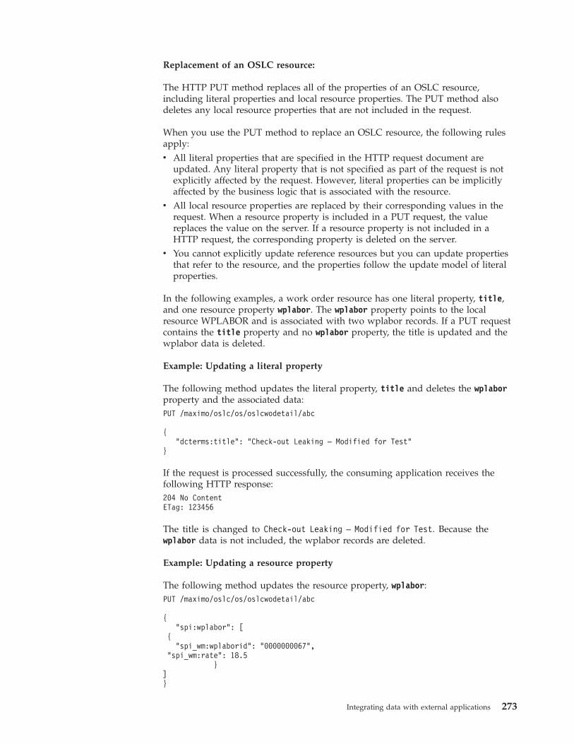
Replacement of an OSLC resource:
The HTTP PUT method replaces all of the properties of an OSLC resource,including literal properties and local resource properties. The PUT method alsodeletes any local resource properties that are not included in the request.
When you use the PUT method to replace an OSLC resource, the following rulesapply:v All literal properties that are specified in the HTTP request document are
updated. Any literal property that is not specified as part of the request is notexplicitly affected by the request. However, literal properties can be implicitlyaffected by the business logic that is associated with the resource.
v All local resource properties are replaced by their corresponding values in therequest. When a resource property is included in a PUT request, the valuereplaces the value on the server. If a resource property is not included in aHTTP request, the corresponding property is deleted on the server.
v You cannot explicitly update reference resources but you can update propertiesthat refer to the resource, and the properties follow the update model of literalproperties.
In the following examples, a work order resource has one literal property, title,and one resource property wplabor. The wplabor property points to the localresource WPLABOR and is associated with two wplabor records. If a PUT requestcontains the title property and no wplabor property, the title is updated and thewplabor data is deleted.
Example: Updating a literal property
The following method updates the literal property, title and deletes the wplaborproperty and the associated data:PUT /maximo/oslc/os/oslcwodetail/abc
{"dcterms:title": "Check-out Leaking – Modified for Test"
}
If the request is processed successfully, the consuming application receives thefollowing HTTP response:204 No ContentETag: 123456
The title is changed to Check-out Leaking – Modified for Test. Because thewplabor data is not included, the wplabor records are deleted.
Example: Updating a resource property
The following method updates the resource property, wplabor:PUT /maximo/oslc/os/oslcwodetail/abc
{“spi:wplabor”: [
{“spi_wm:wplaborid": "0000000067",
"spi_wm:rate": 18.5}
]}
Integrating data with external applications 273
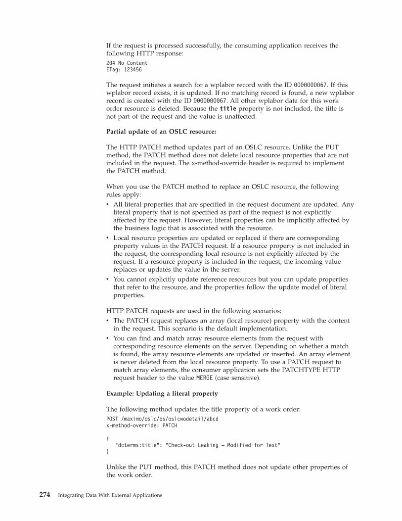
If the request is processed successfully, the consuming application receives thefollowing HTTP response:204 No ContentETag: 123456
The request initiates a search for a wplabor record with the ID 0000000067. If thiswplabor record exists, it is updated. If no matching record is found, a new wplaborrecord is created with the ID 0000000067. All other wplabor data for this workorder resource is deleted. Because the title property is not included, the title isnot part of the request and the value is unaffected.
Partial update of an OSLC resource:
The HTTP PATCH method updates part of an OSLC resource. Unlike the PUTmethod, the PATCH method does not delete local resource properties that are notincluded in the request. The x-method-override header is required to implementthe PATCH method.
When you use the PATCH method to replace an OSLC resource, the followingrules apply:v All literal properties that are specified in the request document are updated. Any
literal property that is not specified as part of the request is not explicitlyaffected by the request. However, literal properties can be implicitly affected bythe business logic that is associated with the resource.
v Local resource properties are updated or replaced if there are correspondingproperty values in the PATCH request. If a resource property is not included inthe request, the corresponding local resource is not explicitly affected by therequest. If a resource property is included in the request, the incoming valuereplaces or updates the value in the server.
v You cannot explicitly update reference resources but you can update propertiesthat refer to the resource, and the properties follow the update model of literalproperties.
HTTP PATCH requests are used in the following scenarios:v The PATCH request replaces an array (local resource) property with the content
in the request. This scenario is the default implementation.v You can find and match array resource elements from the request with
corresponding resource elements on the server. Depending on whether a matchis found, the array resource elements are updated or inserted. An array elementis never deleted from the local resource property. To use a PATCH request tomatch array elements, the consumer application sets the PATCHTYPE HTTPrequest header to the value MERGE (case sensitive).
Example: Updating a literal property
The following method updates the title property of a work order:POST /maximo/oslc/os/oslcwodetail/abcdx-method-override: PATCH
{"dcterms:title": "Check-out Leaking – Modified for Test"
}
Unlike the PUT method, this PATCH method does not update other properties ofthe work order.
274 Integrating Data With External Applications
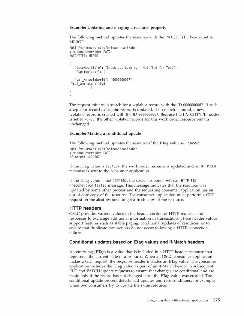
Example: Updating and merging a resource property
The following method updates the resource with the PATCHTYPE header set toMERGE:POST /maximo/oslc/os/oslcwodetail/abcdx-method-override: PATCHPATCHTYPE: MERGE
{"dcterms:title": "Check-out Leaking – Modified for Test",“spi:wplabor”: [
{“spi_wm:wplaborid": "0000000067",
"spi_wm:rate": 18.5}
]}
The request initiates a search for a wplabor record with the ID 0000000067. If sucha wplabor record exists, the record is updated. If no match is found, a newwplabor record is created with the ID 0000000067. Because the PATCHTYPE headeris set to MERGE, the other wplabor records for this work order resource remainunchanged.
Example: Making a conditional update
The following method updates the resource if the ETag value is 1234567:POST /maximo/oslc/os/oslcwodetail/abcdx-method-override: PATCHif-match: 1234567
If the ETag value is 1234567, the work order resource is updated and an HTTP 204response is sent to the consumer application.
If the ETag value is not 1234567, the server responds with an HTTP 412Precondition failed message. This message indicates that the resource wasupdated by some other process and the requesting consumer application has anout-of-date copy of the resource. The consumer application must perform a GETrequest on the abcd resource to get a fresh copy of the resource.
HTTP headersOSLC provides various values in the header section of HTTP requests andresponses to exchange additional information in transactions. These header valuessupport features such as stable paging, conditional updates of resources, or toensure that duplicate transactions do not occur following a HTTP connectionfailure.
Conditional updates based on Etag values and If-Match headers
An entity tag (ETag) is a value that is included in a HTTP header response thatrepresents the current state of a resource. When an OSLC consumer applicationmakes a GET request, the response header includes an ETag value. The consumerapplication includes the ETag value as part of an If-Match header in subsequentPUT and PATCH update requests to ensure that changes are conditional and aremade only if the record has not changed since the ETag value was created. Theconditional update process detects bad updates and race conditions, for examplewhen two consumers try to update the same resource.
Integrating data with external applications 275
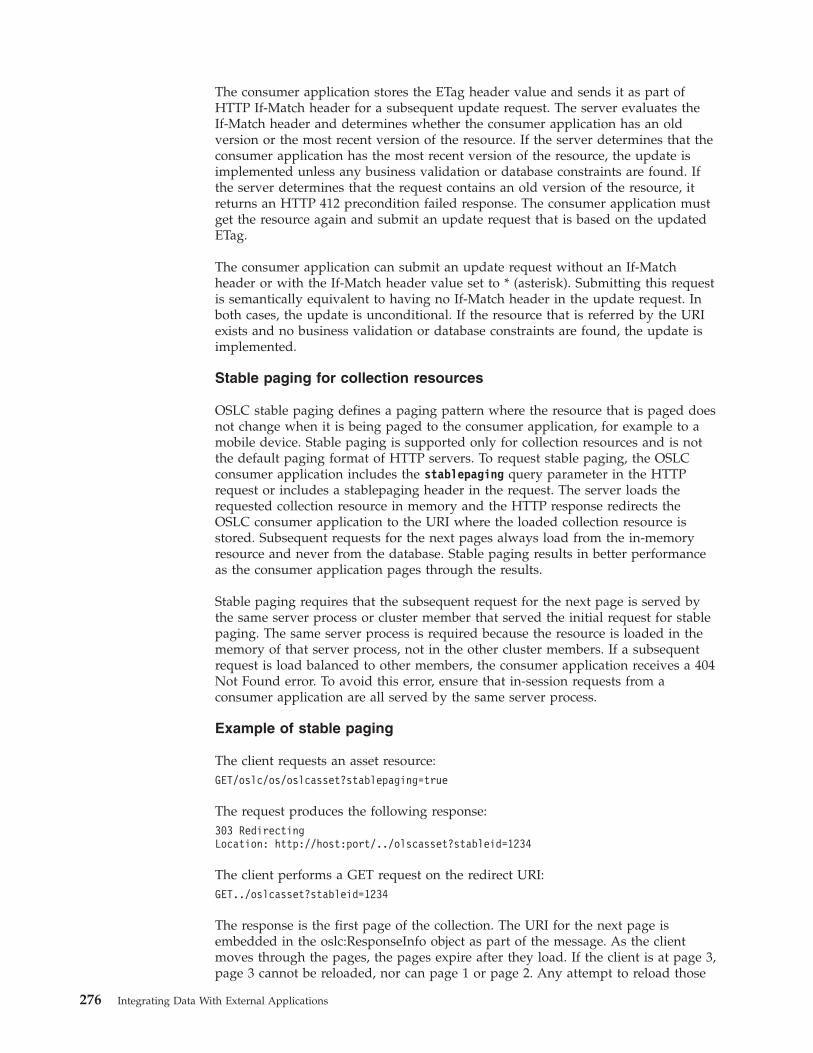
The consumer application stores the ETag header value and sends it as part ofHTTP If-Match header for a subsequent update request. The server evaluates theIf-Match header and determines whether the consumer application has an oldversion or the most recent version of the resource. If the server determines that theconsumer application has the most recent version of the resource, the update isimplemented unless any business validation or database constraints are found. Ifthe server determines that the request contains an old version of the resource, itreturns an HTTP 412 precondition failed response. The consumer application mustget the resource again and submit an update request that is based on the updatedETag.
The consumer application can submit an update request without an If-Matchheader or with the If-Match header value set to * (asterisk). Submitting this requestis semantically equivalent to having no If-Match header in the update request. Inboth cases, the update is unconditional. If the resource that is referred by the URIexists and no business validation or database constraints are found, the update isimplemented.
Stable paging for collection resources
OSLC stable paging defines a paging pattern where the resource that is paged doesnot change when it is being paged to the consumer application, for example to amobile device. Stable paging is supported only for collection resources and is notthe default paging format of HTTP servers. To request stable paging, the OSLCconsumer application includes the stablepaging query parameter in the HTTPrequest or includes a stablepaging header in the request. The server loads therequested collection resource in memory and the HTTP response redirects theOSLC consumer application to the URI where the loaded collection resource isstored. Subsequent requests for the next pages always load from the in-memoryresource and never from the database. Stable paging results in better performanceas the consumer application pages through the results.
Stable paging requires that the subsequent request for the next page is served bythe same server process or cluster member that served the initial request for stablepaging. The same server process is required because the resource is loaded in thememory of that server process, not in the other cluster members. If a subsequentrequest is load balanced to other members, the consumer application receives a 404Not Found error. To avoid this error, ensure that in-session requests from aconsumer application are all served by the same server process.
Example of stable paging
The client requests an asset resource:GET/oslc/os/oslcasset?stablepaging=true
The request produces the following response:303 RedirectingLocation: http://host:port/../olscasset?stableid=1234
The client performs a GET request on the redirect URI:GET../oslcasset?stableid=1234
The response is the first page of the collection. The URI for the next page isembedded in the oslc:ResponseInfo object as part of the message. As the clientmoves through the pages, the pages expire after they load. If the client is at page 3,page 3 cannot be reloaded, nor can page 1 or page 2. Any attempt to reload those
276 Integrating Data With External Applications
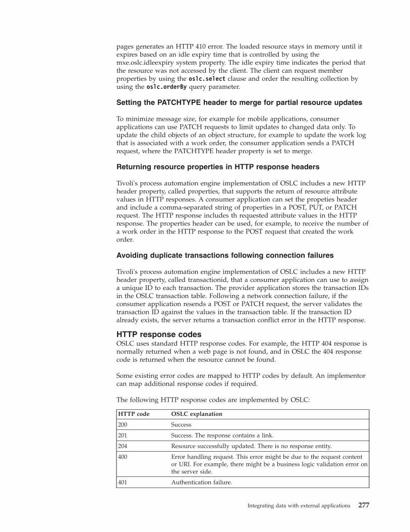
pages generates an HTTP 410 error. The loaded resource stays in memory until itexpires based on an idle expiry time that is controlled by using themxe.oslc.idleexpiry system property. The idle expiry time indicates the period thatthe resource was not accessed by the client. The client can request memberproperties by using the oslc.select clause and order the resulting collection byusing the oslc.orderBy query parameter.
Setting the PATCHTYPE header to merge for partial resource updates
To minimize message size, for example for mobile applications, consumerapplications can use PATCH requests to limit updates to changed data only. Toupdate the child objects of an object structure, for example to update the work logthat is associated with a work order, the consumer application sends a PATCHrequest, where the PATCHTYPE header property is set to merge.
Returning resource properties in HTTP response headers
Tivoli's process automation engine implementation of OSLC includes a new HTTPheader property, called properties, that supports the return of resource attributevalues in HTTP responses. A consumer application can set the propeties headerand include a comma-separated string of properties in a POST, PUT, or PATCHrequest. The HTTP response includes th requested attribute values in the HTTPresponse. The properties header can be used, for example, to receive the number ofa work order in the HTTP response to the POST request that created the workorder.
Avoiding duplicate transactions following connection failures
Tivoli's process automation engine implementation of OSLC includes a new HTTPheader property, called transactionid, that a consumer application can use to assigna unique ID to each transaction. The provider application stores the transaction IDsin the OSLC transaction table. Following a network connection failure, if theconsumer application resends a POST or PATCH request, the server validates thetransaction ID against the values in the transaction table. If the transaction IDalready exists, the server returns a transaction conflict error in the HTTP response.
HTTP response codesOSLC uses standard HTTP response codes. For example, the HTTP 404 response isnormally returned when a web page is not found, and in OSLC the 404 responsecode is returned when the resource cannot be found.
Some existing error codes are mapped to HTTP codes by default. An implementorcan map additional response codes if required.
The following HTTP response codes are implemented by OSLC:
HTTP code OSLC explanation
200 Success
201 Success. The response contains a link.
204 Resource successfully updated. There is no response entity.
400 Error handling request. This error might be due to the request contentor URI. For example, there might be a business logic validation error onthe server side.
401 Authentication failure.
Integrating data with external applications 277
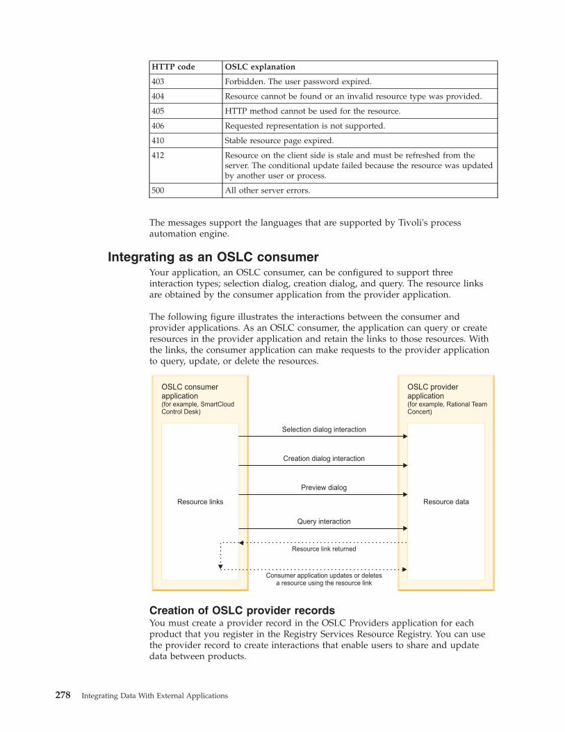
HTTP code OSLC explanation
403 Forbidden. The user password expired.
404 Resource cannot be found or an invalid resource type was provided.
405 HTTP method cannot be used for the resource.
406 Requested representation is not supported.
410 Stable resource page expired.
412 Resource on the client side is stale and must be refreshed from theserver. The conditional update failed because the resource was updatedby another user or process.
500 All other server errors.
The messages support the languages that are supported by Tivoli's processautomation engine.
Integrating as an OSLC consumerYour application, an OSLC consumer, can be configured to support threeinteraction types; selection dialog, creation dialog, and query. The resource linksare obtained by the consumer application from the provider application.
The following figure illustrates the interactions between the consumer andprovider applications. As an OSLC consumer, the application can query or createresources in the provider application and retain the links to those resources. Withthe links, the consumer application can make requests to the provider applicationto query, update, or delete the resources.
Resource links
OSLC consumerapplication(for example, SmartCloudControl Desk)
Selection dialog interaction
Resource data
OSLC providerapplication(for example, Rational TeamConcert)
Creation dialog interaction
Preview dialog
Query interaction
Resource link returned
Consumer application updates or deletesa resource using the resource link
Creation of OSLC provider recordsYou must create a provider record in the OSLC Providers application for eachproduct that you register in the Registry Services Resource Registry. You can usethe provider record to create interactions that enable users to share and updatedata between products.
278 Integrating Data With External Applications
Registry Services:
Registry Services is a Jazz™ for Service Management integration service thatprovides the mechanisms through which Open Services for Lifecycle Collaboration(OSLC) services, resources, and consumers can use the OSLC interface to work inan integrated service management environment.
Registry Services uses the provider registry to track the capabilities that areavailable in the environment and uses the resource registry to track the resourcesthat can be managed for the environments. It tracks the resources that can bemanaged for the environments by using the resource registry. Tivoli's processautomation engine uses the provider registry and the resource registry to integratemultiple products.
Provider registry
The provider registry is a Registry Services directory that contains services that areprovided by multiple products across different domains. The provider registrytracks all the service providers in an environment, provides information about howto contact them, and lists the type of action they perform.
As an OSLC consumer, when you create a selection window, a creation window, ora query interaction, you can configure the interaction to discover service providersin the provider registry.
The OSLC provider currently offers no support for registering the application'sservice providers to the provider registry.
Resource registry
The resource registry is a Registry Services directory that contains resources thatare managed or tracked by multiple products across different domains.
As an OSLC consumer, you can use the resource registry to query resources. Whenyou create a query interaction, you can configure the public URI of the providerrecord to point to the resource registry, and you can also configure the defaultPROVIDERREGISTRY end point.
The OSLC provider currently offers no support for registering the application'sresources to the resource registry.
Service providers:
A service provider is a container or collection of related data, such as a project, auser database, or a module. Service providers support the grouping of similarresources, such as defects or tasks, that can be configured for integration.
A service provider in an OSLC provider application contains the resource data thatcan be linked to consumer application data through integration of the applications.To integrate a consumer application and a provider application, the consumer mustdiscover or identify the service providers that are available in the providerapplication.
The OSLC Providers application supports the following ways of discovery ofservice providers:v Catalog list
Integrating data with external applications 279
v Single service providerv Provider registry
To use the catalog list or the single service provider for discovery, in the OSLCProviders application, you specify a URI in the Service Provider List URI field.The URI can link to a service provider catalog, a service provider listing, or anindividual service provider.
To use the provider registry for discovery, in the OSLC Providers application, youselect the Use Provider Registry check box. In the End Points application, apredefined HTTP endpoint that is named PROVIDERREGISTRY is used to identifythe connection information to the provider registry.
The PROVIDERREGISTRY endpoint specifies a provider registry where OSLCprovider applications can register service provider data. The endpoint requiressome configuration before it can be used. The HTTP endpoint for the providerregistry is distinct from the OAuth or HTTP endpoints that are used during therunning of interactions between integrated applications.
Resource types and shape documents:
A resource type identifies the type of data, such as a change request, that is linkedbetween integrated applications. A resource type can have an associated shapedocument. A shape document is similar to an XML schema in the way that itdefines the data structure of the resource.
In the OSLC Providers application, you use the Add/Modify Resource Typesaction to create resource types. You create a resource type for each type of datathat at least one provider supports, and that you want to link to. The providerapplication must support the resource type through a service provider for theresource type to be available for an OSLC interaction.
A resource type can be used with multiple interactions for a provider. Resourcetypes are available to use with multiple OSLC providers that support the sameresource type.
Resource data from the provider application can be made available to theconsumer application as usages. A usage is a subclass of the resource data. Forexample, a resource type of change request might have usages of defect and task.
A shape document is a Resource Description Framework (RDF) file that provides adescription of the resource data types that can be used in an interaction. When youcreate a resource type, you can import a shape document for the resource type.The shape document contains a list of attributes of the resource type.
Endpoints in OSLC integration:
An endpoint is the entry point to a service, a process, an application, or a topicdestination. Two types of endpoints can be used in OSLC integration. Anintegration endpoint is used for OSLC integration between a consumer applicationand a provider application. It specifies how a consumer application communicateswith the OSLC provider application. The integration endpoint can be an OAuthendpoint or an HTTP endpoint. A provider registry endpoint is used only if themethod specified for service provider discovery is through the Provider Registry.
280 Integrating Data With External Applications
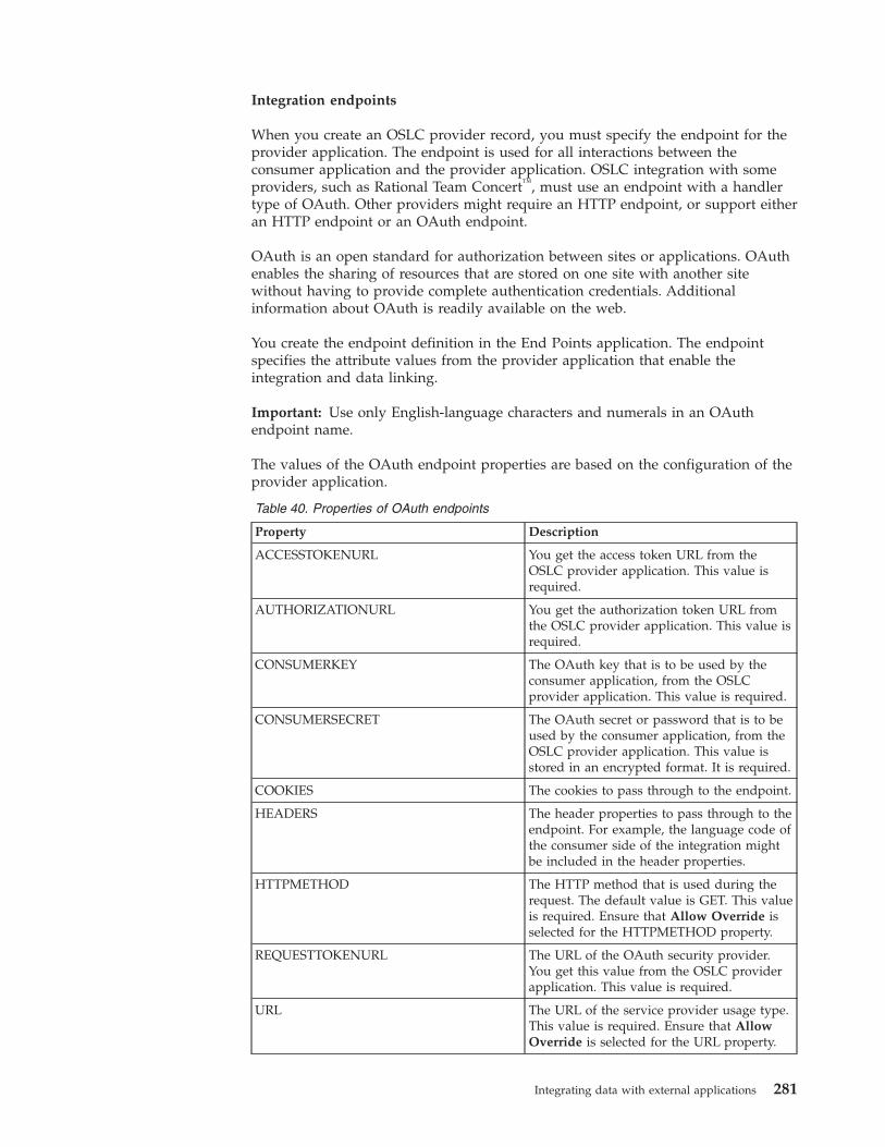
Integration endpoints
When you create an OSLC provider record, you must specify the endpoint for theprovider application. The endpoint is used for all interactions between theconsumer application and the provider application. OSLC integration with someproviders, such as Rational Team Concert™, must use an endpoint with a handlertype of OAuth. Other providers might require an HTTP endpoint, or support eitheran HTTP endpoint or an OAuth endpoint.
OAuth is an open standard for authorization between sites or applications. OAuthenables the sharing of resources that are stored on one site with another sitewithout having to provide complete authentication credentials. Additionalinformation about OAuth is readily available on the web.
You create the endpoint definition in the End Points application. The endpointspecifies the attribute values from the provider application that enable theintegration and data linking.
Important: Use only English-language characters and numerals in an OAuthendpoint name.
The values of the OAuth endpoint properties are based on the configuration of theprovider application.
Table 40. Properties of OAuth endpoints
Property Description
ACCESSTOKENURL You get the access token URL from theOSLC provider application. This value isrequired.
AUTHORIZATIONURL You get the authorization token URL fromthe OSLC provider application. This value isrequired.
CONSUMERKEY The OAuth key that is to be used by theconsumer application, from the OSLCprovider application. This value is required.
CONSUMERSECRET The OAuth secret or password that is to beused by the consumer application, from theOSLC provider application. This value isstored in an encrypted format. It is required.
COOKIES The cookies to pass through to the endpoint.
HEADERS The header properties to pass through to theendpoint. For example, the language code ofthe consumer side of the integration mightbe included in the header properties.
HTTPMETHOD The HTTP method that is used during therequest. The default value is GET. This valueis required. Ensure that Allow Override isselected for the HTTPMETHOD property.
REQUESTTOKENURL The URL of the OAuth security provider.You get this value from the OSLC providerapplication. This value is required.
URL The URL of the service provider usage type.This value is required. Ensure that AllowOverride is selected for the URL property.
Integrating data with external applications 281
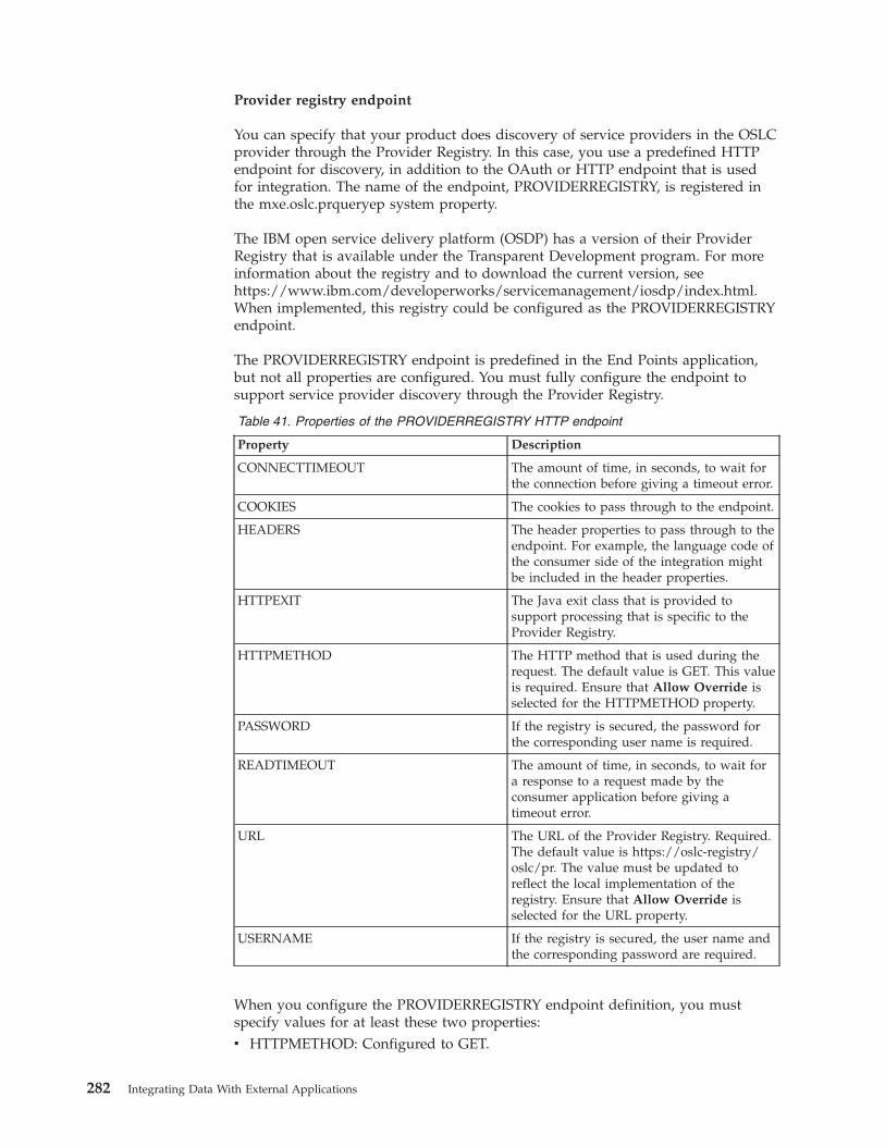
Provider registry endpoint
You can specify that your product does discovery of service providers in the OSLCprovider through the Provider Registry. In this case, you use a predefined HTTPendpoint for discovery, in addition to the OAuth or HTTP endpoint that is usedfor integration. The name of the endpoint, PROVIDERREGISTRY, is registered inthe mxe.oslc.prqueryep system property.
The IBM open service delivery platform (OSDP) has a version of their ProviderRegistry that is available under the Transparent Development program. For moreinformation about the registry and to download the current version, seehttps://www.ibm.com/developerworks/servicemanagement/iosdp/index.html.When implemented, this registry could be configured as the PROVIDERREGISTRYendpoint.
The PROVIDERREGISTRY endpoint is predefined in the End Points application,but not all properties are configured. You must fully configure the endpoint tosupport service provider discovery through the Provider Registry.
Table 41. Properties of the PROVIDERREGISTRY HTTP endpoint
Property Description
CONNECTTIMEOUT The amount of time, in seconds, to wait forthe connection before giving a timeout error.
COOKIES The cookies to pass through to the endpoint.
HEADERS The header properties to pass through to theendpoint. For example, the language code ofthe consumer side of the integration mightbe included in the header properties.
HTTPEXIT The Java exit class that is provided tosupport processing that is specific to theProvider Registry.
HTTPMETHOD The HTTP method that is used during therequest. The default value is GET. This valueis required. Ensure that Allow Override isselected for the HTTPMETHOD property.
PASSWORD If the registry is secured, the password forthe corresponding user name is required.
READTIMEOUT The amount of time, in seconds, to wait fora response to a request made by theconsumer application before giving atimeout error.
URL The URL of the Provider Registry. Required.The default value is https://oslc-registry/oslc/pr. The value must be updated toreflect the local implementation of theregistry. Ensure that Allow Override isselected for the URL property.
USERNAME If the registry is secured, the user name andthe corresponding password are required.
When you configure the PROVIDERREGISTRY endpoint definition, you mustspecify values for at least these two properties:v HTTPMETHOD: Configured to GET.
282 Integrating Data With External Applications
v URL: Has a default value. Update the value to reflect the local implementationof the registry.
You also might need to configure the USER and PASSWORD values, depending onthe security configuration of the Provider Registry.
Single sign-on
If you plan to use single sign-on, you must set the COOKIES property for yourHTTP endpoint to LtpaToken2.
Designing an OSLC interactionOSLC integration establishes links between the data in one of your userapplications and the data in an external OSLC provider application. You use theOSLC Providers application to integrate applications by designing OSLCinteractions.
The OSLC Providers application supports the creation of OSLC interactions thatare generated from the user interface. You can design the following three types ofinteractions that let your users link their application data to provider resource data:v A creation interaction lets the user create resource data in the OSLC provider
application and link that resource data to an application record.v A selection interaction lets the user select existing resource data in the OSLC
provider application and link that resource data to an application record.v A query interaction lets the user select a pre-defined query in the OSLC provider
application and retrieve resource data.
The following records must be in place before you can design an interaction:v An OAuth or HTTP integration endpoint record for the provider application
must exist in the End Points application.v A record for the OSLC provider application must be defined in the OSLC
Providers application.v One or more provider resource types must be available. You add resource types
on the Add/Modify Resource Types window in the OSLC Providers application.
The Create OSLC Interaction wizard in the OSLC Providers application takes youthrough three steps to design an OSLC selection interaction. The wizard adds anextra step for an OSLC creation interaction and two extra steps for an OSLC queryinteraction.
Example: Designing an OSLC creation or selection interaction:
You want to design an OSLC interaction so that users of the Service Requestsapplication can create a defect in Rational Team Concert, the provider application.The defect that is created is linked to a service request in the Service Requestsapplication.
Preparatory work
In the OSLC Providers application, you create a provider record for Rational TeamConcert. You specify the OAuth endpoint and the public URI for Rational TeamConcert, and you specify how the service provider is identified.
Integrating data with external applications 283
By using the Add/Modify Resource Types action, you add the resource type ortypes that are supported in Rational Team Concert and specify that users can linkfrom the Service Requests application.
Define interaction and select usage URI: step 1
You select the Create OSLC Interaction action.
You specify Create Defect as the name of the OSLC interaction for the RationalTeam Concert record. You select CREATIONDIALOG as the interaction type.
You select a resource type, such as change request, from the value list. The list ispopulated with the resource type or types that you created earlier.
The Rational Team Concert login page is displayed because you must log in toRational Team Concert to continue.
After you log in, the Usage URI value list is populated from Rational TeamConcert with the resource usage types for the selected resource type. You select thedefect usage type. You can optionally specify a usage URI.
Select service provider and association property: step 2
In step 2, you specify whether all Rational Team Concert service providers areavailable for the interaction, or whether only a single service provider is available.You can also identify an association property, so that a link can be established fromthe provider application, Rational Team Concert, to the consumer application,Service Requests.
You use the default selection, which is that all service providers are available.When a user of the Service Requests application initiates the interaction in theService Requests application and multiple service providers support the selectedresource and usage combination, a selection window opens. For example, theselection window can show a list of Rational Team Concert projects that supportdefects. The user can select the service provider or container in which to create thedefect.
The other option is to specify an individual service provider URI. In that case, theService Requests application connects directly to the service provider that youspecify.
To enable a link from Rational Team Concert to the Service Requests application,you must specify the association property. The association property is tied to theRational Team Concert resource. If a shape document is associated with theresource type, values that you can choose for the association property come fromthe shape document. If no shape document is associated with the resource type,you can specify an association property. The association property is displayed inthe Rational Team Concert user interface, and the property is populated with a linkto the service request. A Rational Team Concert user can click the link to open theService Requests application and view the related service request in Rational TeamConcert.
284 Integrating Data With External Applications
Select consumer application for OSLC interaction: step 3
In step 3, you specify the consumer application that will interact with the providerapplication, Rational Team Concert. The consumer application is the ServiceRequest application.
The default setting is that user interface changes in the consumer application aregenerated automatically by the wizard. If you maintain the default setting, youmust specify the application tab to which the interaction table and button areadded.
You specify that the tab, table window, and button are to be added to the RelatedRecords tab of the Service Requests application. By default, the push-button nameis the name that you specified for the interaction: Create Defect. You can changethe button name.
For the button to be visible to users, you must specify the security groups that areauthorized to run the interaction. Only users in the groups that you authorize cansee the button and create a defect in Rational Team Concert.
Alternatively, you can clear the Create Interaction Tab check box and use theApplication Designer to create all user interface changes in the Service Requestsapplication.
Specify interaction field mappings: step 4
Step 4 is available for creation interactions only. You can optionally map data fromthe consumer application to target fields in the provider application. When theuser clicks the button to create a resource, the fields are mapped to the providerwindow that is displayed in the consumer application. For example, you wantService Requests users to see the service request number and description that isprefilled in fields on the Rational Team Concert Create Resource window. You canprovide more field mappings, or revise the field mapping, even after you completethe interaction.
The shape document for the resource identifies attributes that support links. Fromyour application, select only fields that contain links to map to target fields thatsupport links. Ensure that the target field is a field that is visible in the userinterface of the provider application window so that the mapped data is visible.
You want to map the service request description to the defect description in theRational Team Concert window. You specify :description as the source mappingexpression, and description as the target resource property.
Create multiple interactions
You can create multiple interactions for a consumer application. For example, youmight also want to create a selection interaction for the Service Requestsapplication. In the selection window, a user can click a button to select an existingresource, such as a defect, in Rational Team Concert. If you create multipleinteractions for the same resource type and usage combination in the sameapplication tab, the push buttons are added to the same tab and table window.
If you also design a selection interaction for the Service Requests application, usershave the following options:v Create a defect, and link the service request to the new defect.
Integrating data with external applications 285
v Select an existing defect, and link the service request to that.
You also might design an additional creation interaction for a supported resourcetype or usage type, such as task. A different resource type and usage combinationgenerates a separate tab and table window for the additional interaction button.
Review new interactions in the consumer application
After you complete the interaction, you must log in again. The new login grantsthe updated security access that you specified in step 3. After you log in, younavigate to the Service Requests application to review the user interface changes.At any time, you can use the Application Designer application to refine or add tothe user interface changes that were auto-generated in the Service Requestsapplication.
You can test the button or buttons to ensure that the Rational Team Concertwindow is shown in the Service Request application as expected. If the window isnot shown, or data is in unexpected fields, faulty data mapping might be thecause. You can review and revise data mapping for the interaction in the Mappingtable of the OSLC provider record.
If users of the Service Request application cannot see the newly added buttons thatlink to Rational Team Concert, ensure that the users have logged in again and thatthey belong to the security groups that you authorized. Also ensure that the usershave valid Rational Team Concert login credentials.
Modification of OSLC creation or selection interactions
After you complete the design of the OSLC interaction, the changes that you canmake to it are limited. You can update the association property, and you can revisethe field mapping.
Specifying a new association property establishes a new property name thatprovides a link from the provider application to the consumer application.
In the Interaction Mappings table, you can revise any existing mapping, deletemapping, or add mapping. The shape document for the resource identifiesattributes that support links. From the consumer application, you select only thefields that contain links to map to target fields that support links. Ensure that thetarget field is one that is visible on the user interface of the provider applicationwindow, so that the mapped data is visible.
You also can specify a Java class to use as part of the mapping logic. You can use aJava class when the field mapping definitions that you provide are not sufficient.Specify the Java class in the Interaction Mapping Class field. A mapping class canbe provided whether field mapping exists or not.
Deletion of OSLC creation and selection interactions
Deletion of the interaction is possible only if there are no existing links within theconsumer application that reference the interaction. All related application linksmust be deleted before an interaction can be deleted from an OSLC providerrecord.
When you delete an interaction, the corresponding user interface changes that weremade when the interaction was designed are updated. The button for the
286 Integrating Data With External Applications
interaction is removed from the application. The table window and tab are alsoremoved, but only if the wizard-created tab and table window where the buttonexisted does not contain buttons for other interactions. The relationship andsignature option that were created for the interaction are also deleted.
If you manually configured the user interface changes for the interaction, you mustuse the Application Designer to remove those changes.
Orphan links
Links that are generated between the object record for the consumer applicationand the provider application resource are stored in the OSLCLINK database table.
If you delete an object record that has links, the OSLCLINK table then contains oneor more orphan links that are associated with the deleted object record.
The OSLCDeleteLinks cron task deletes orphan links. By default, theOSLCDeleteLinks cron task is set to run once a day. You can view and edit thecron task in the Cron Task Setup application
Example: Designing an OSLC query interaction:
You want to design an OSLC interaction so that users of the Assets application canrun a query and retrieve resource data from a provider, such as IBM TivoliApplication Dependency Discovery Manager.
Preparatory work
In the OSLC Providers application, Resource Registry is the default provider forquery interactions. The PROVIDERREGISTRY endpoint is specified as part of thedefault settings, but you must configure the end-point properties and specify thepublic URI for Resource Registry. You must also specify how the service provideris identified.
By using the Add/Modify Resource Types action, you add the resource type ortypes that are supported in Resource Registry and associate a shape documentwith the resource type if available. You can also specify that users can link to theResource Registry from the Assets application.
Define interaction and select usage URI: step 1
You select the Create OSLC Interaction action.
You specify COMPUTER as the name of the OSLC interaction and selectQUERYCAPABILITY as the interaction type.
You select a resource type, such as COMPUTERSY, from the value list. The list ispopulated with the resource type or types that you created earlier.
You can optionally specify a usage URI. The Usage URI value list is populatedfrom the Resource Registry with the resource usage type or types for the selectedresource type. If you do not specify a usage URI, the default usage type for theresource type is used.
Integrating data with external applications 287
Select service provider and link property: step 2
In step 2, you specify whether all service providers are available for the interaction,or whether only a single service provider is available. You can also identify a linkproperty and a link label, so that a link can be established from the providerapplication, Resource Registry, to the consumer application, Assets.
You use the default selection, which is that only the Resource Registry serviceprovider is available. When a user of the Assets application initiates the interactionby running a query and multiple service providers support the selected resourceand usage combination, a selection window opens. For example, the selectionwindow can show a list of service providers that contain data that is on thespecified resource. The user can select the service provider on which to base thequery.
The other option is to specify an individual service provider URI. The query is runbased on the service provider that you specify. The link property is used to retrievethe resource data from the Resource Registry for the provider. The link and thelink label are displayed to the user in the consumer application when the queryresults are provided.
To enable a link from Resource Registry to the Assets application, the providerapplication must support the use of a link property. The link property is tied to theresource in the Resource Registry. If a shape document is associated with theresource type, values that you can choose for the link property come from theshape document. If no shape document is associated with the resource type, youcan specify a link property and link label.
Select consumer application for OSLC interaction: step 3
In step 3, you specify the product application that interacts with the providerapplication, Resource Registry. The consumer application can be any application inthe product, but this example uses the Assets application.
The default setting is that the push button is generated automatically in theapplication that is specified. If you maintain the default setting, you must specifythe application tab to which the interaction button is added to support the queryinteraction.
You specify that the button is to be added to the Main tab of the Assetsapplication. By default, the push-button label is the same as the name that youspecified for the interaction: Computer. You can change the button label.
For the button to be visible to users, you must specify the security groups that areauthorized to run the interaction. Only users in the groups that you authorize cansee the button and run the query to retrieve the resource data.
Specify queries and query parameters: step 4
In step 4, you build the queries for the interaction. The queries are used to querythe resource data in the Resource Registry. The Select clause identifies theattributes that are selected from the resource. You can specify an asterisk (*) toretrieve all values or specify a comma-separated list of resource attributes from theshape document to filter the list of values to be retrieved.
288 Integrating Data With External Applications
You can define the WHERE condition of the query by using one of the followingmethods:v Implement a Java class to define the WHERE condition.v Populate the WHERE condition.v Configure the WHERE condition by using the parameter values. The parameter
values are selected from the main object of the application and compared againstthe attributes of the resource data in the provider application.
The queries are run in the order that is specified in the queries table. If the firstcondition is not met, all subsequent queries are processed in sequence until aquery condition is met. When a condition is met, the resource data is retrieved andreturned to the user in the consumer application. You can also identify the orderbyquery parameter that orders the data returned in the response of the query.
Queries that are created during the design of the interaction are not validated.Therefore, you might create queries that generate messages during run time. Forexample, you might create the following query condition:Query Query Type Property Operand Mapped Expression Is Literal?10 Parameter http://open-services.net/ns/crtv#%7Dmanufacturer IN IBM, Dell Checked
But during run time, an error is generated because the query is searching for oneattribute "IBM, Dell" rather than two attributes "IBM","Dell". The followingexample shows the correct attribute format:Query Query Type Property Operand Mapped Expression Is Literal?10 Parameter http://open-services.net/ns/crtv#%7Dmanufacturer IN "IBM","Dell" Checked
Specify the interaction group: step 5
In step 5, you can optionally add the query interaction to an interaction group andspecify a condition for the group if one does not exist.
An interaction group allows you to group multiple related queries together undera single user interface control. By specifying an interaction group, you allow theuser to execute multiple interactions to different providers based on the conditionthat is associated with the interaction within the group.
All the interactions in the group are based on the same main object and resourcetype. If you add a query interaction to an interaction group, that interaction is onlyrun as part of the group. The query interaction is not run independently. The orderof interactions in the group determines the sequence in which the query for theinteraction group is run.
You specify the CICOMPUTERSY interaction group and the XYZ condition. If youcreated an interaction group, you can specify extra details for the interaction groupby using the Add/Modify Interaction Groups action. In the Assets application,when the user clicks the button to run a query and a condition is met, the queryresults are displayed in the Preview window.
Review new interactions in the consumer application
After you create the query interaction, you must log in again. The new login grantsthe updated security access that you specified in step 3. After you log in, you cannavigate to the Assets application to review the user interface changes.
You can test the button to ensure that it is shown in the Assets application asexpected. You can run the query to verify that the query is valid and that resource
Integrating data with external applications 289
data is returned. If no results are returned, the query parameters might beincorrect. Review the query parameters in the OSLC Providers application andupdate them as needed.
If users cannot see the newly added button after they log in again, ensure that theusers belong to the security groups that you authorized.
Modification of OSLC query interactions
After you complete the design of the OSLC query interaction, the changes that youcan make to it are limited. You can update the link property, update the queryparameters, and you can revise the field mapping.
Specifying a new link property establishes a new property name that provides alink from the provider application to the consumer application.
In the Query Mappings table, you can revise any existing mapping, deletemapping, or add mapping. The shape document for the resource identifiesattributes that support links. From the consumer application, you select only thefields that contain links to map to target fields that support links. Ensure that thetarget field is one that is visible on the user interface of the provider applicationwindow so that the mapped data is visible.
You also can specify a Java class to use as part of the mapping logic. You can use aJava class when the field mapping definitions that you provide are not sufficient.Specify the Java class in the Query Mapping Class field. A mapping class can beprovided whether field mapping exists or not.
The SELECT clause of the query interaction can be updated after the interaction iscreated.
Deletion of OSLC query interactions
Deletion of the query interaction is possible only if the interaction is not tied to aninteraction group. You must remove the interaction from a group before you deletethe interaction.
When you delete an interaction, the corresponding user interface changes that weremade when the interaction was designed are updated. The button for theinteraction is removed from the application. The relationship and signature optionthat were created for the interaction are also deleted.
Creating interaction groupsYou can use interaction groups to collate multiple query interactions under a singleuser interface control, such as a button. These query interactions can be for a singleprovider or multiple providers.
Before you begin
Before you can create an interaction group, you must create one or more queryinteractions.
About this task
Each query interaction in the group is executed and returns data to the user basedon its conditions. If a query interaction contains a condition that is based on the
290 Integrating Data With External Applications
current application data, the interaction group uses that data to execute only theappropriate queries. The query results from multiple queries are combined anddisplayed in the resulting view.
To create an OSLC interaction, you must be in the base language. You can alsocreate an interaction group in the query interaction wizard.
Procedure1. In the OSLC Providers application, select the Add/Modify Interaction Groups
action.2. Add a new row, and specify a name for the interaction group and the main
object that you want to associate with the group.3. Optional: If you want to associate the interaction group with multiple
providers, select the Support the Combined View of Multiple Providers checkbox.
4. On the Interactions tab, specify at least one interaction to be run as part of thegroup. The interactions that are available for selection are based on the mainobject that is specified for the interaction groups.
5. On the Applications tab, specify the application to which you want to add theinteraction group.
6. Optional: If the main object for the interaction group is not a main object forthe application that is specified, you must specify a relationship. If arelationship does not exist between the application and the main object thatyou specified for the interaction group, you must create or modify arelationship on the Relationships tab in the Database Configurationapplication.
7. Specify a label for a button, a Detail Menu item, or both depending on whereyou want the interaction to be available from in the consumer application.
8. On the Security Groups tab, select the security group that applies to theapplication and interaction group.
9. To add an interaction group to a Detail Menu item, select the ApplicationMenu tab, specify the location in the consumer application where the group isto be added, click OK, and save the group. The existing fields in the consumerapplication are shown in the Select Detail Menu dialog box.
Example: Running an OSLC interactionAs an application user, you can run OSLC interactions between applications thatan integration designer integrated. You start theOSLC interaction by clicking abutton in the consumer application. Depending on the type of interaction, you cancreate a resource record in the external provider application or link to an existingresource in the provider application.
In this example, your application is the consumer and Rational Team Concert is theprovider. However, this process can also work with anyOSLC provider.
You use the Service Requests application to enter requests for fixes to the softwarethat your team is developing. Your integration designer used the OSLC Providersapplication to integrate the Service Requests application with the Rational TeamConcert application. Two OSLC interactions were created. In the Service Requestsapplication, there is now a tab that is labeled Defects in the Related Records tab.The tab has a Defects window and two push buttons in the window: Create Defectand Select Defect.
Integrating data with external applications 291
You can now enter a service request and create an associated defect in RationalTeam Concert at the same time, without leaving the Service Requests application.Or you can associate the request with an existing resource in Rational TeamConcert, by using the Select Defect button.
Creating a defect
In the Service Requests application, you create a service request, provide adescription and other information, and save the request. You open the RelatedRecords tab, and click the Create Defect button on the Defects tab.
Because you are creating a resource record in an external application, RationalTeam Concert, you must sign in to Rational Team Concert. The Rational TeamConcert login window is displayed. After you provide your user ID and password,the Create Resource window is displayed. The Create Resource window is aRational Team Concert window, now available to you in the Service Requestsapplication as a result of the OSLC integration.
You specify the type of resource to create, a defect. You also must provideinformation in the Summary field, and specify the project or container to file thedefect against.
Your integration designer mapped the Service Request Description field to theRational Team Concert Description property when the interaction was created. As aresult, your service request description is in the Description field on the CreateResource window. You can edit the description if necessary.
Previewing provider application resource record data
Creation of the record in Rational Team Concert also creates a row in the Defectstable in the Service Requests application. The Description field containsinformation about the linked resource in Rational Team Concert. The table row alsoshows the URL of the linked resource record.
The Description field has an information icon, a small blue circle with an “i” in it.You can hover the cursor over the information icon to display a window thatshows data from the defect record in Rational Team Concert. (If you are not signedin to the provider application, hovering over the information icon displays amessage and a link to sign in.If the provider application does not support OSLCpreviews, a second icon appears and you can click on this icon to see a preview.)
You can use the preview window to check the status and other information aboutthe Rational Team Concert defect record from within the Service Requestsapplication.
Selecting a defect
In the Service Requests application, you enter a second service request. The requestis to fix an instance of a problem that was previously reported, and for which adefect exists in Rational Team Concert. For the second request, you want to link tothe existing defect, rather than create a defect record. On the Defects table on theRelated Records tab, you click Select Defect.
You might need to select the container, such as the Rational Team Concert project,for the defect, if the provider application supports multiple containers.
292 Integrating Data With External Applications
On the Select Resource window, you specify Defect as the type of resource thatyou want to select. Provide search information, such as the defect number ordescription, to display the defect or defects that match your search criteria. Whenyou select a defect and click OK, the link to the Rational Team Concert defectresource is established. A row for the defect is added to the Defects table in theService Requests application. You can use the information icon to display defectinformation, just as you can for the row that you added by creating a defect.
Public URI changesIf an OSLC provider application is moved to another server or its public URIchanges for another reason, you can change the public URI on the OSLC providerrecord. When you update the public URI, URIs that are based on the public URIalso change, which prevents links from breaking.
In the OSLC Providers application, you use the Change Public URI action tospecify the new public URI for an OSLC provider. After you change the publicURI, URIs that are based on the public URI, such as service provider URIs andresource URIs, are also changed. Updating the links to match the new public URImaintains the links as active, viable links.
Migration of OSLC integrationsYou can migrate an OSLC provider definition and its related interactions from oneinstance of your product to another. For example, you might set up an OSLCintegration in a development or test environment. After you establish that theintegration is working properly, you can migrate it to a production environment.
Migration of OSLC integrations takes advantage of existing Migration Managerapplication features and is largely done in the Migration Manager application. TheOSLC Providers application has an action to generate the package that is to bemigrated.
Before you run the Migrate OSLC Provider action, you do preparatory work in theMigration Manager application. An OSLCPROVIDER package definition isprovided in the Migration Manager application. For the OSLCPROVIDER packagedefinition, you specify a target database or file destination for the package that yougenerate in the OSLC Providers application.
You use the Migrate OSLC Provider action in the OSLC Providers application togenerate the package that you then manage in the Migration Manager application.The package contains the OSLC provider record, the associated interactions, andthe associated user interface changes in the integrated consumer application orapplications.
After you run the Migrate OSLC Provider action, a system message is displayed.The final line of the log message shows the name of the package. The package islisted on the Package tab of the OSLCPROVIDER package definition in theMigration Manager application in the source environment.
In the target environment, you use the Migration Manager application to importand deploy the package.
If you use a custom Java mapping file in your OSLC integration, the custom Javamapping file does not get included in the package. You must manually move thecustom mapping file and the corresponding class file to the target environment, ormanually add them to the package.
Integrating data with external applications 293

The Migrate OSLC Provider action generates a package for the current OSLCprovider record only. If you have multiple OSLC provider records, you mustmigrate each one individually.
The Migration Manager does not support the migration of interaction groups. Tomigrate the objects in an interaction group, you can build a new object structurethat uses the following objects:OSLCINTGROUPOSLCGRPAPPSOSLCGRPAPPMENUOSLCGRPMEMBERS
You must include the new object structure in the OSLCPROVIDER migrationpackage.
Manual UI modificationDesigning OSLC interactions between applications requires multiple user interface(UI) changes in the consumer application. Several scenarios might lead you to usethe Application Designer application to make or refine UI changes as part of theintegration.
Manual implementation of UI changes and security for interactions:
If you choose to not have the wizard auto-generate user interface (UI) changes inthe consumer application, you must modify the UI yourself. The user interfacemust make the interaction available to users through a push button. If you do notselect security groups in the wizard, you must specify the security groups thathave access to the interaction.
Even when you do not auto-generate user interface changes, creation of an OSLCinteraction creates a link relationship and a push-button signature option. The linkrelationship name is based on the specified resource type or usage. The signatureoption name is based on the interaction name. The relationship name and thesignature option name are listed in the interaction details on the OSLC Providertab. You need these two values when you manually implement UI changes.
Use the Application Designer application to modify the user interface of theconsumer application. You must create a push button so that the OSLC interactioncan be executed to create a link. And you must provide a tab with a table to holdthe links to resources in the provider application. Typically, you provide the buttonand the link table together on the same tab.
Use the Security Groups application to specify the groups that have access to thepush button. Only users in the groups that you authorize can see the button anduse it to display the provider application window and run the interaction.
User interface refinements:
You might want to make refinements or additions to the consumer application userinterface (UI) even when the UI changes are auto-generated.
After you design an OSLC interaction that auto-generates the user interfacechanges, your review of the application UI might reveal that revisions arewarranted. For example, you might want to edit the labels on the new tab, tablewindow, or push button. Or you might want to adjust the positioning of UIelements. Use the Application Designer application to modify or add UI elements.
294 Integrating Data With External Applications
During interaction design, you can specify that all service providers are to beavailable for the interaction in the consumer application. In these cases, a SelectContainer window is displayed when the interaction is initiated. The window isused to specify which service provider or container to use for the interaction. Youmight want to provide help grid text for the Select Container window. Forexample, you might add help grid text to indicate that the choices representprojects, or databases, or some other resource container. You also might relabel thewindow title to add clarity to what the user is to select.
Translation of untranslated UI elements:
You use the Application Designer application to modify and translate some userinterface (UI) elements, such as tooltips for icons, that are added by the interactiondesign.
Some user interface elements that are added by the design of an OSLC interactiondo not appear in the language appropriate for the interface, because interactionsmust be created in the base language. The elements are added after the original UIelements were translated, before deployment of the application. To translate the UIelements into the language of the application UI, use the Application Designerapplication to modify the untranslated text elements.
OSLC propertiesYou can use system properties to help manage Open Services for LifecycleCollaboration (OSLC) application integration.
Table 42. OSLC properties
Property Description Default value
mxe.oslc.collectioncount Represents the total count of the OSLC collection. 0
mxe.oslc.defaultep Represents the default OSLC endpoint. OSLCDEFAULT
mxe.oslc.defaultformat Represents the default format for OSLC. oslcjson
mxe.oslc.dfltconsumerversion Represents the default OSLC version that theconsumer uses.
2.0
mxe.oslc.dfltversion Represents the default OSLC version for an OSLCprovider.
2.0
mxe.oslc.enableprovider Enables the OSLC provider. 1
mxe.oslc.idleexpiry Represents the time in seconds that the system canbe idle before the sessions expires.
300
mxe.oslc.prcreateep Represents the Provider Registry Create Endpoint.
mxe.oslc.preferproviderdesc Specifies whether the OSLC Provider description ispreferred for resource registry reconciled URIs.
true
mxe.oslc.prettyjson Represents the pretty print JSON. 1
mxe.oslc.prettyrdf Represents the pretty print RDF. 1
mxe.oslc.prqueryep Represents the Provider Registry Query Endpoint. PROVIDERREGISTRY
mxe.oslc.webappurl Represents the Provider Public URI. http://localhost/maximo/oslc/
Integration queriesThe integration framework supports queries from external systems. The externalsystem sends an XML message to query the integration framework and theintegration framework returns an XML message as a response to the query. Youcan execute a query for object structure and enterprise services by using HTTP,Java™ Remote Method Invocation (RMI), or a Simple Object Access Protocol(SOAP) request in a web service.
Integrating data with external applications 295
Support for XML queries is based on the system Query By Example (QBE)capability that is available from the List tab of most applications. XML-basedqueries provide the same query support that is provided in the applications exceptfor attribute searches that are available in some system applications. Integrationquery time outs are controlled by the mxe.db.Query.Timeout system property.Related concepts:“REST API” on page 226The Representational State Transfer (REST) application programming interface(API) provides a way for external applications to query and update applicationdata in Tivoli's process automation engine.
Query servicesObject structure services and enterprise services support query operations. Anexternal source can use a service to run a query and to retrieve data from a system.In both cases, the object structure schema defines the XML content for the queryrequest and the query response.
For an object structure that has more than two levels of business objects, the queryframework supports the use of business object attributes in the top two levels ofthe request XML. The query response XML contains all the objects in the objectstructure.
All system-provided object structures with a Consumed By value ofINTEGRATION, support the query operation by default. You can configure anobject structure to support the query operation only and no other operations thatsupport updating objects. You can use the Object Structures application to createadditional object structures which provide support for the query operation.
Creating an enterprise service queryAn external source can use an enterprise service to run a query and to retrievedata from a system.
About this task
A sample enterprise service query, MXINVBALQInterface, is provided. You can usethis sample as a reference when you create query enterprise services.
Procedure1. If one does not exist, create an object structure containing the objects that the
query needs to access.2. Define an enterprise service that implements the object structure you intend to
use for the query.3. Specify Query as the operation on the enterprise service.4. Associate the enterprise service with an external system, and enable the
external system and its enterprise service.
Web service queriesQuery services that are created in the Enterprise Services application and theObject Structures applications can be deployed as web services. To supportquerying, you must configure enterprise web services to bypass the JMS queues.
296 Integrating Data With External Applications
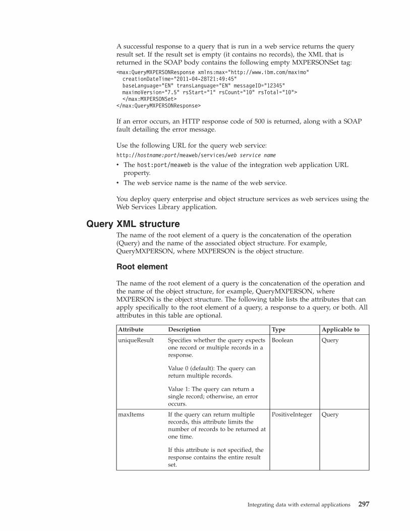
A successful response to a query that is run in a web service returns the queryresult set. If the result set is empty (it contains no records), the XML that isreturned in the SOAP body contains the following empty MXPERSONSet tag:<max:QueryMXPERSONResponse xmlns:max="http://www.ibm.com/maximo"
creationDateTime="2011-04-28T21:49:45"baseLanguage="EN" transLanguage="EN" messageID="12345"maximoVersion="7.5" rsStart="1" rsCount="10" rsTotal="10"></max:MXPERSONSet>
</max:QueryMXPERSONResponse>
If an error occurs, an HTTP response code of 500 is returned, along with a SOAPfault detailing the error message.
Use the following URL for the query web service:http://hostname:port/meaweb/services/web service name
v The host:port/meaweb is the value of the integration web application URLproperty.
v The web service name is the name of the web service.
You deploy query enterprise and object structure services as web services using theWeb Services Library application.
Query XML structureThe name of the root element of a query is the concatenation of the operation(Query) and the name of the associated object structure. For example,QueryMXPERSON, where MXPERSON is the object structure.
Root element
The name of the root element of a query is the concatenation of the operation andthe name of the object structure, for example, QueryMXPERSON, whereMXPERSON is the object structure. The following table lists the attributes that canapply specifically to the root element of a query, a response to a query, or both. Allattributes in this table are optional.
Attribute Description Type Applicable to
uniqueResult Specifies whether the query expectsone record or multiple records in aresponse.
Value 0 (default): The query canreturn multiple records.
Value 1: The query can return asingle record; otherwise, an erroroccurs.
Boolean Query
maxItems If the query can return multiplerecords, this attribute limits thenumber of records to be returned atone time.
If this attribute is not specified, theresponse contains the entire resultset.
PositiveInteger Query
Integrating data with external applications 297
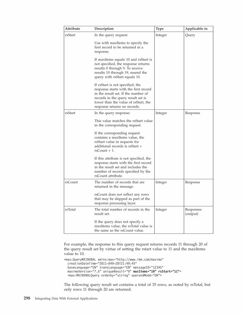
Attribute Description Type Applicable to
rsStart In the query request:
Use with maxItems to specify thefirst record to be returned in aresponse.
If maxItems equals 10 and rsStart isnot specified, the response returnsresults 0 through 9. To receiveresults 10 through 19, resend thequery with rsStart equals 10.
If rsStart is not specified, theresponse starts with the first recordin the result set. If the number ofrecords in the query result set islower than the value of rsStart, theresponse returns no records.
Integer Query
rsStart In the query response:
This value matches the rsStart valuein the corresponding request.
If the corresponding requestcontains a maxItems value, thersStart value in requests foradditional records is rsStart +rsCount + 1.
If this attribute is not specified, theresponse starts with the first recordin the result set and includes thenumber of records specified by thersCount attribute.
Integer Response
rsCount The number of records that arereturned in the message.
rsCount does not reflect any rowsthat may be skipped as part of theresponse processing layer.
Integer Response
rsTotal The total number of records in theresult set.
If the query does not specify amaxItems value, the rsTotal value isthe same as the rsCount value.
Integer Responses(output)
For example, the response to this query request returns records 11 through 20 ofthe query result set by virtue of setting the rstart value to 11 and the maxItemsvalue to 10.<max:QueryMXINVBAL xmlns:max="http://www.ibm.com/maximo"
creationDateTime="2011-049-28T21:49:45"baseLanguage="EN" transLanguage="EN" messageID="12345"maximoVersion="7.5" uniqueResult="0" maxItems="10" rsStart="11"><max:MXINVBALQuery orderby="string" operandMode="OR">
The following query result set contains a total of 35 rows, as noted by rsTotal, butonly rows 11 through 20 are returned.
298 Integrating Data With External Applications
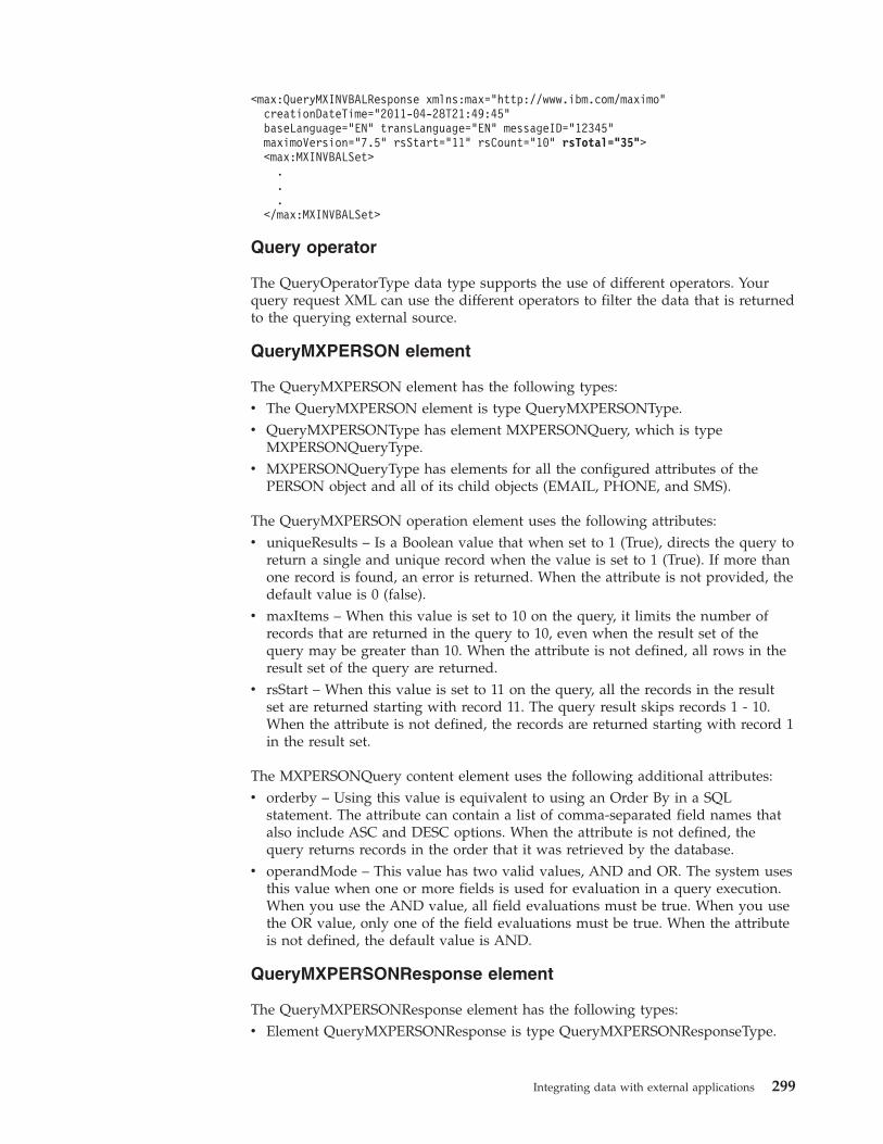
<max:QueryMXINVBALResponse xmlns:max="http://www.ibm.com/maximo"creationDateTime="2011-04-28T21:49:45"baseLanguage="EN" transLanguage="EN" messageID="12345"maximoVersion="7.5" rsStart="11" rsCount="10" rsTotal="35"><max:MXINVBALSet>
.
.
.</max:MXINVBALSet>
Query operator
The QueryOperatorType data type supports the use of different operators. Yourquery request XML can use the different operators to filter the data that is returnedto the querying external source.
QueryMXPERSON element
The QueryMXPERSON element has the following types:v The QueryMXPERSON element is type QueryMXPERSONType.v QueryMXPERSONType has element MXPERSONQuery, which is type
MXPERSONQueryType.v MXPERSONQueryType has elements for all the configured attributes of the
PERSON object and all of its child objects (EMAIL, PHONE, and SMS).
The QueryMXPERSON operation element uses the following attributes:v uniqueResults – Is a Boolean value that when set to 1 (True), directs the query to
return a single and unique record when the value is set to 1 (True). If more thanone record is found, an error is returned. When the attribute is not provided, thedefault value is 0 (false).
v maxItems – When this value is set to 10 on the query, it limits the number ofrecords that are returned in the query to 10, even when the result set of thequery may be greater than 10. When the attribute is not defined, all rows in theresult set of the query are returned.
v rsStart – When this value is set to 11 on the query, all the records in the resultset are returned starting with record 11. The query result skips records 1 - 10.When the attribute is not defined, the records are returned starting with record 1in the result set.
The MXPERSONQuery content element uses the following additional attributes:v orderby – Using this value is equivalent to using an Order By in a SQL
statement. The attribute can contain a list of comma-separated field names thatalso include ASC and DESC options. When the attribute is not defined, thequery returns records in the order that it was retrieved by the database.
v operandMode – This value has two valid values, AND and OR. The system usesthis value when one or more fields is used for evaluation in a query execution.When you use the AND value, all field evaluations must be true. When you usethe OR value, only one of the field evaluations must be true. When the attributeis not defined, the default value is AND.
QueryMXPERSONResponse element
The QueryMXPERSONResponse element has the following types:v Element QueryMXPERSONResponse is type QueryMXPERSONResponseType.
Integrating data with external applications 299
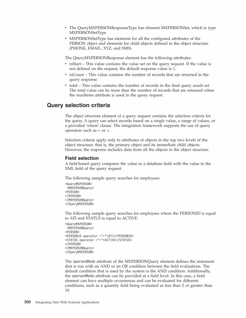
v The QueryMXPERSONResponseType has element MXPERSONSet, which is typeMXPERSONSetType.
v MXPERSONSetType has elements for all the configured attributes of thePERSON object and elements for child objects defined in the object structure(PHONE, EMAIL, XYZ, and SMS).
The QueryMXPERSONResponse element has the following attributes:v rsStart – This value contains the value set on the query request. If the value is
not defined on the request, the default response value is 1.v rsCount – This value contains the number of records that are returned in the
query response.v total – This value contains the number of records in the final query result set.
The total value can be more than the number of records that are returned whenthe maxItems attribute is used in the query request.
Query selection criteria
The object structure element of a query request contains the selection criteria forthe query. A query can select records based on a single value, a range of values, ora provided 'where' clause. The integration framework supports the use of queryoperators such as = or >.
Selection criteria apply only to attributes of objects in the top two levels of theobject structure; that is, the primary object and its immediate child objects.However, the response includes data from all the objects in the object structure.
Field selectionA field-based query compares the value in a database field with the value in theXML field of the query request.
The following sample query searches for employees:<QueryMXPERSON><MXPERSONQuery><PERSON></PERSON></MXPERSONQuery></QueryMXPERSON>
The following sample query searches for employees where the PERSONID is equalto ATI and STATUS is equal to ACTIVE.<QueryMXPERSON><MXPERSONQuery><PERSON><PERSONID operator ="=">ATI</PERSONID><STATUS operator ="=">ACTIVE</STATUS></PERSON></MXPERSONQuery></QueryMXPERSON>
The operandMode attribute of the MXPERSONQuery element defines the statementthat is run with an AND or an OR condition between the field evaluations. Thedefault condition that is used by the system is the AND condition. Additionally,the operandMode attribute can be provided at a field level. In this case, a fieldelement can have multiple occurrences and can be evaluated for differentconditions, such as a quantity field being evaluated as less than 2 or greater than10.
300 Integrating Data With External Applications
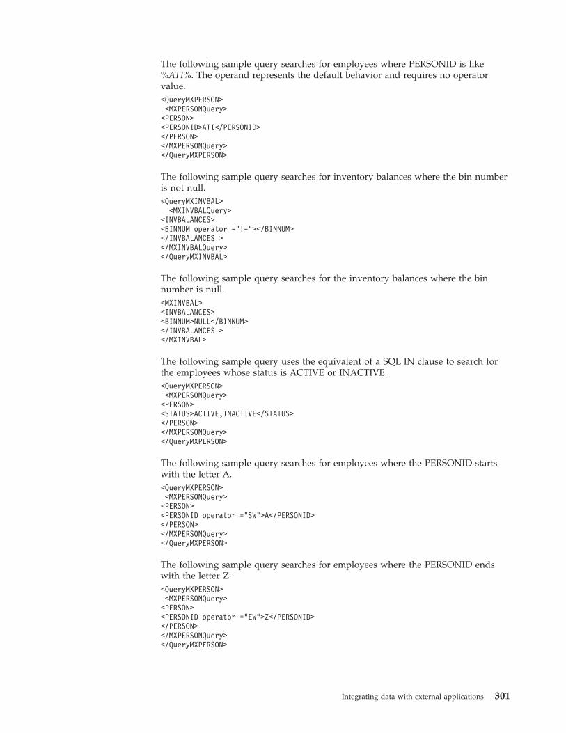
The following sample query searches for employees where PERSONID is like%ATI%. The operand represents the default behavior and requires no operatorvalue.<QueryMXPERSON><MXPERSONQuery><PERSON><PERSONID>ATI</PERSONID></PERSON></MXPERSONQuery></QueryMXPERSON>
The following sample query searches for inventory balances where the bin numberis not null.<QueryMXINVBAL>
<MXINVBALQuery><INVBALANCES><BINNUM operator =”!="></BINNUM></INVBALANCES ></MXINVBALQuery></QueryMXINVBAL>
The following sample query searches for the inventory balances where the binnumber is null.<MXINVBAL><INVBALANCES><BINNUM>NULL</BINNUM></INVBALANCES ></MXINVBAL>
The following sample query uses the equivalent of a SQL IN clause to search forthe employees whose status is ACTIVE or INACTIVE.<QueryMXPERSON><MXPERSONQuery><PERSON><STATUS>ACTIVE,INACTIVE</STATUS></PERSON></MXPERSONQuery></QueryMXPERSON>
The following sample query searches for employees where the PERSONID startswith the letter A.<QueryMXPERSON><MXPERSONQuery><PERSON><PERSONID operator ="SW">A</PERSONID></PERSON></MXPERSONQuery></QueryMXPERSON>
The following sample query searches for employees where the PERSONID endswith the letter Z.<QueryMXPERSON><MXPERSONQuery><PERSON><PERSONID operator ="EW">Z</PERSONID></PERSON></MXPERSONQuery></QueryMXPERSON>
Integrating data with external applications 301
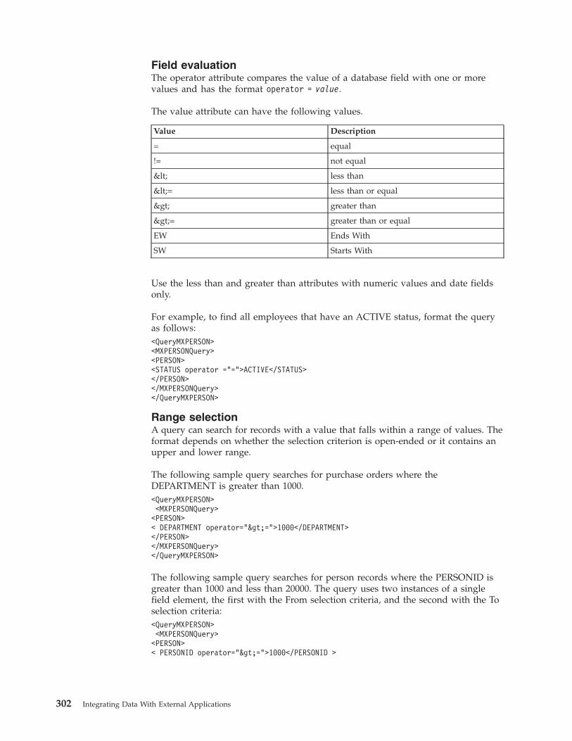
Field evaluationThe operator attribute compares the value of a database field with one or morevalues and has the format operator = value.
The value attribute can have the following values.
Value Description
= equal
!= not equal
< less than
<= less than or equal
> greater than
>= greater than or equal
EW Ends With
SW Starts With
Use the less than and greater than attributes with numeric values and date fieldsonly.
For example, to find all employees that have an ACTIVE status, format the queryas follows:<QueryMXPERSON><MXPERSONQuery><PERSON><STATUS operator ="=">ACTIVE</STATUS></PERSON></MXPERSONQuery></QueryMXPERSON>
Range selectionA query can search for records with a value that falls within a range of values. Theformat depends on whether the selection criterion is open-ended or it contains anupper and lower range.
The following sample query searches for purchase orders where theDEPARTMENT is greater than 1000.<QueryMXPERSON><MXPERSONQuery><PERSON>< DEPARTMENT operator=">=">1000</DEPARTMENT></PERSON></MXPERSONQuery></QueryMXPERSON>
The following sample query searches for person records where the PERSONID isgreater than 1000 and less than 20000. The query uses two instances of a singlefield element, the first with the From selection criteria, and the second with the Toselection criteria:<QueryMXPERSON><MXPERSONQuery><PERSON>< PERSONID operator=">=">1000</PERSONID >
302 Integrating Data With External Applications
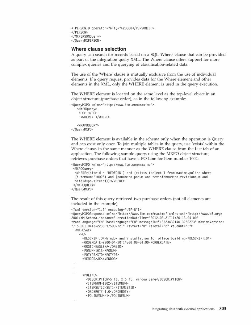
< PERSONID operator="<=">20000</PERSONID ></PERSON></MXPERSONQuery></QueryMXPERSON>
Where clause selectionA query can search for records based on a SQL 'Where' clause that can be providedas part of the integration query XML. The Where clause offers support for morecomplex queries and the querying of classification-related data.
The use of the 'Where' clause is mutually exclusive from the use of individualelements. If a query request provides data for the Where element and otherelements in the XML, only the WHERE element is used in the query execution.
The WHERE element is located on the same level as the top-level object in anobject structure (purchase order), as in the following example:<QueryMXPO xmlns="http://www.ibm.com/maximo">
<MXPOQuery><PO> </PO><WHERE> </WHERE>
</MXPOQUERY></QueryMXPO>
The WHERE element is available in the schema only when the operation is Queryand can exist only once. To join multiple tables in the query, use ‘exists' within theWhere clause, in the same manner as the WHERE clause from the List tab of anapplication. The following sample query, using the MXPO object structure,retrieves purchase orders that have a PO Line for Item number 1002:<QueryMXPO xmlns="http://www.ibm.com/maximo"><MXPOQuery><WHERE>(siteid = ’BEDFORD’) and (exists (select 1 from maximo.poline where(i temnum=’1002’) and (ponum=po.ponum and revisionnum=po.revisionnum andsiteid=po.siteid)))</WHERE></MXPOQUERY></QueryMXPO>
The result of this query retrieved two purchase orders (not all elements areincluded in the example):<?xml version="1.0" encoding="UTF-8"?><QueryMXPOResponse xmlns="http://www.ibm.com/maximo" xmlns:xsi="http://www.w3.org/2001/XMLSchema-instance" creationDateTime="2012-03-21T11:20:13-04:00"transLanguage="EN" baseLanguage="EN" messageID="1332343214013260273" maximoVersion="7 5 20110413-2230 V7500-721" rsStart="0" rsTotal="2" rsCount="2">
<MXPOSet><PO>
<DESCRIPTION>Window and installation for office building</DESCRIPTION><ORDERDATE>2000-04-20T14:00:00-04:00</ORDERDATE><ORGID>EAGLENA</ORGID><PONUM>1013</PONUM><POTYPE>STD</POTYPE><VENDOR>JK</VENDOR>
.
.
.<POLINE>
<DESCRIPTION>5 ft. X 6 ft. window pane</DESCRIPTION><ITEMNUM>1002</ITEMNUM><ITEMSETID>SET1</ITEMSETID><ORDERQTY>1.0</ORDERQTY><POLINENUM>1</POLINENUM>
.
Integrating data with external applications 303
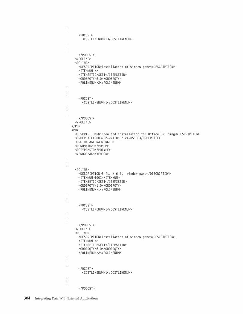
.
.<POCOST>
<COSTLINENUM>1</COSTLINENUM>...
</POCOST></POLINE><POLINE>
<DESCRIPTION>Installation of window pane</DESCRIPTION><ITEMNUM /><ITEMSETID>SET1</ITEMSETID><ORDERQTY>6.0</ORDERQTY><POLINENUM>2</POLINENUM>
.
.
.<POCOST>
<COSTLINENUM>1</COSTLINENUM>...
</POCOST></POLINE>
</PO><PO>
<DESCRIPTION>Window and installation for Office Building</DESCRIPTION><ORDERDATE>2003-02-27T10:07:24-05:00</ORDERDATE><ORGID>EAGLENA</ORGID><PONUM>1029</PONUM><POTYPE>STD</POTYPE><VENDOR>JK</VENDOR>
.
.
.<POLINE>
<DESCRIPTION>5 ft. X 6 ft. window pane</DESCRIPTION><ITEMNUM>1002</ITEMNUM><ITEMSETID>SET1</ITEMSETID><ORDERQTY>1.0</ORDERQTY><POLINENUM>1</POLINENUM>
.
.
.<POCOST>
<COSTLINENUM>1</COSTLINENUM>...
</POCOST></POLINE><POLINE>
<DESCRIPTION>Installation of window pane</DESCRIPTION><ITEMNUM /><ITEMSETID>SET1</ITEMSETID><ORDERQTY>6.0</ORDERQTY><POLINENUM>2</POLINENUM>
.
.
.<POCOST>
<COSTLINENUM>1</COSTLINENUM>...
</POCOST>
304 Integrating Data With External Applications
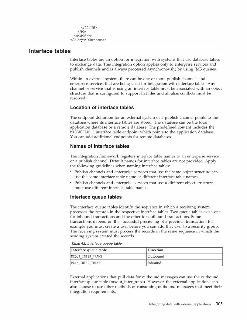
</POLINE></PO>
</MXPOSet></QueryMXPOResponse>
Interface tablesInterface tables are an option for integration with systems that use database tablesto exchange data. This integration option applies only to enterprise services andpublish channels and is always processed asynchronously, by using JMS queues.
Within an external system, there can be one or more publish channels andenterprise services that are being used for integration with interface tables. Anychannel or service that is using an interface table must be associated with an objectstructure that is configured to support flat files and all alias conflicts must beresolved.
Location of interface tables
The endpoint definition for an external system or a publish channel points to thedatabase where its interface tables are stored. The database can be the localapplication database or a remote database. The predefined content includes theMXIFACETABLE interface table endpoint which points to the application database.You can add additional endpoints for remote databases.
Names of interface tables
The integration framework registers interface table names to an enterprise serviceor a publish channel. Default names for interface tables are not provided. Applythe following guidelines when naming interface tables:v Publish channels and enterprise services that use the same object structure can
use the same interface table name or different interface table names.v Publish channels and enterprise services that use a different object structure
must use different interface table names.
Interface queue tables
The interface queue tables identify the sequence in which a receiving systemprocesses the records in the respective interface tables. Two queue tables exist, onefor inbound transactions and the other for outbound transactions. Sometransactions depend on the successful processing of a previous transaction, forexample you must create a user before you can add that user to a security group.The receiving system must process the records in the same sequence in which thesending system created the records.
Table 43. Interface queue table
Interface queue table Direction
MXOUT_INTER_TRANS Outbound
MXIN_INTER_TRANS Inbound
External applications that pull data for outbound messages can use the outboundinterface queue table (mxout_inter_trans). However, the external applications canalso choose to use other methods of consuming outbound messages that meet theirintegration requirements.
Integrating data with external applications 305
All inbound and outbound transactions must have a record that is inserted into thecorresponding inbound or outbound queue table. This record contains a TRANSIDvalue, a unique identifier that identifies the interface table to which the transactiondata is written. The corresponding interface table uses the TRANSID value toidentify the record or records that are associated with the transaction. You canidentify the contents of a transaction by looking up all the records with a givenTRANSID value in the corresponding interface table.
The sequence of TRANSID identifies the sequence in which records are processedby the integration framework. For example, when users and security groups areentered into the system, the TRANSID values for the user record must be lowerthan the TRANSID values for the security group records that reference that user.
The difference between the MXIN_INTER_TRANS and MXOUT_INTER_TRANSqueue tables is the direction of the interface table records that they track. Theexternal system must write to the MXIN_INTER_TRANS queue table, and theintegration framework must read from it. The integration framework writes to theMXOUT_INTER_TRANS queue table, and the external system reads from it.
The external system can use the MXOUT_INTER_TRANS table or retrieveoutbound records from interface tables. The interface queue tables are generatedthe first time that you create interface tables for an endpoint. Each endpoint has itsown interface queue tables and a counter for maintaining the outbound TRANSIDvalue.
Creation of interface tablesWhen an enterprise service and a publish channel use the same interface table, theCreate Interface Tables window displays a list of interface tables based on theuniqueness of the interface table name and its corresponding endpoint.
You can create interface tables for enterprise services and publish channels whenthe associated object structures are marked as flat supported. The Support FlatStructure check box must be selected on the object structure. All alias conflictsmust also be resolved for the object structure before you can create an interfacetable.
You can create interface tables for data synchronization on enterprise services andon publish channels. Interface tables do not support Query and Invoke operations.You can create interface tables for a specific endpoint. You must identify where thetables are created.
The database location that is referenced by the endpoint can be a local database ora remote database. When you create interface tables on a local database, thecolumns are registered in the system data dictionary. Local interface tables that usea database table and a database column show all updates (except insertions anddeletions) to a base column attribute (such as data type) when you run thedatabase configuration operation. When columns are added to or deleted from thebase table, you must regenerate the corresponding enterprise service and thepublish channel interface tables to apply the column changes. No changes areapplied in the remote databases. You must regenerate remote interface tables toapply the column changes.
306 Integrating Data With External Applications
Regeneration of interface tablesWhen columns are added or deleted from the system database tables, you mustregenerate all local and remote interface tables that are associated with those objectstructures.
You regenerate interface tables by using the Create Interface Tables action in theExternal Systems application. If you select the Rename Existing check box, theapplication backs up existing data in the corresponding interface table to theINTERFACETABLENAME_BAK table.
If necessary, you can restore the data to the new table. Depending on theconfiguration of the multitenancy environment, you may need to request theassistance of the system provider to access the data that you want to restore. If youdo not back up the table, the table is dropped and the data is lost when youregenerate the table. You cannot regenerate an interface table when theMXIN_INTER_TRANS queue table contains a record that points to that interfacetable. When a row exists in that queue table, the corresponding inboundtransaction is ready to process, or the inbound transaction is in error.
The interface table creation process does not check for records in theMXOUT_INTER_TRANS queue table.
Deletion of interface tables and recordsWhen related inbound transaction records are successfully processed in aninterface table, the corresponding record is deleted from the MXIN_INTER_TRANSqueue table. The deletion indicates that the transaction was delivered successfullyto the inbound JMS queue.
Records are deleted from the MXIN_INTER_TRANS queue table and not from theindividual interface tables. The system administrator determines when and how todelete records from the interface tables.
For outbound transactions, the external system must manage the deletion andarchiving of data in the queue table and interface tables. You cannot deleteinterface tables in the user interface or by deleting the corresponding objectstructure. An administrator must manage the archiving of data in the interfacetables and can drop the table, if necessary.
Format of interface tablesAn interface table has the same format as its corresponding object structure,including persistent and nonpersistent columns and excluding any columns thatare excluded from the object structure.
The interface table includes additional columns that identify the sequence in whichthe sending system writes, and the receiving system processes the records in thevarious interface tables.
Key columns
If the interface table represents a hierarchical object structure with parent-childobject relationships, the table does not include any part of the child object keycolumns that are included in the parent object key columns. For example,PERSONID is a key column in the PERSON, PHONE, EMAIL, and SMS records.
Integrating data with external applications 307
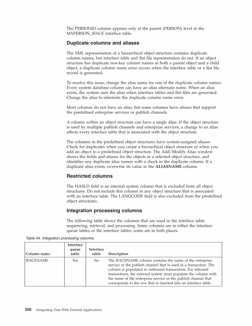
The PERSONID column appears only at the parent (PERSON) level in theMXPERSON_IFACE interface table.
Duplicate columns and aliases
The XML representation of a hierarchical object structure contains duplicatecolumn names, but interface table and flat file representation do not. If an objectstructure has duplicate non-key column names in both a parent object and a childobject, a duplicate column name error occurs when the interface table or a flat filerecord is generated.
To resolve this issue, change the alias name for one of the duplicate column names.Every system database column can have an alias alternate name. When an aliasexists, the system uses the alias when interface tables and flat files are generated.Change the alias to eliminate the duplicate column name error.
Most columns do not have an alias, but some columns have aliases that supportthe predefined enterprise services or publish channels.
A column within an object structure can have a single alias. If the object structureis used by multiple publish channels and enterprise services, a change to an aliasaffects every interface table that is associated with the object structure.
The columns in the predefined object structures have system-assigned aliases.Check for duplicates when you create a hierarchical object structure or when youadd an object to a predefined object structure. The Add/Modify Alias windowshows the fields and aliases for the objects in a selected object structure, andidentifies any duplicate alias names with a check in the duplicate column. If aduplicate alias exists, overwrite its value in the ALIASNAME column.
Restricted columns
The HASLD field is an internal system column that is excluded from all objectstructures. Do not include this column in any object structure that is associatedwith an interface table. The LANGCODE field is also excluded from the predefinedobject structures.
Integration processing columns
The following table shows the columns that are used in the interface tablesequencing, retrieval, and processing. Some columns are in either the interfacequeue tables or the interface tables; some are in both places.
Table 44. Integration processing columns
Column name
Interfacequeuetable
Interfacetable Description
IFACENAME Yes No The IFACENAME column contains the name of the enterpriseservice or the publish channel that is used in a transaction. Thecolumn is populated in outbound transactions. For inboundtransactions, the external system must populate the column withthe name of the enterprise service or the publish channel thatcorresponds to the row that is inserted into an interface table.
308 Integrating Data With External Applications
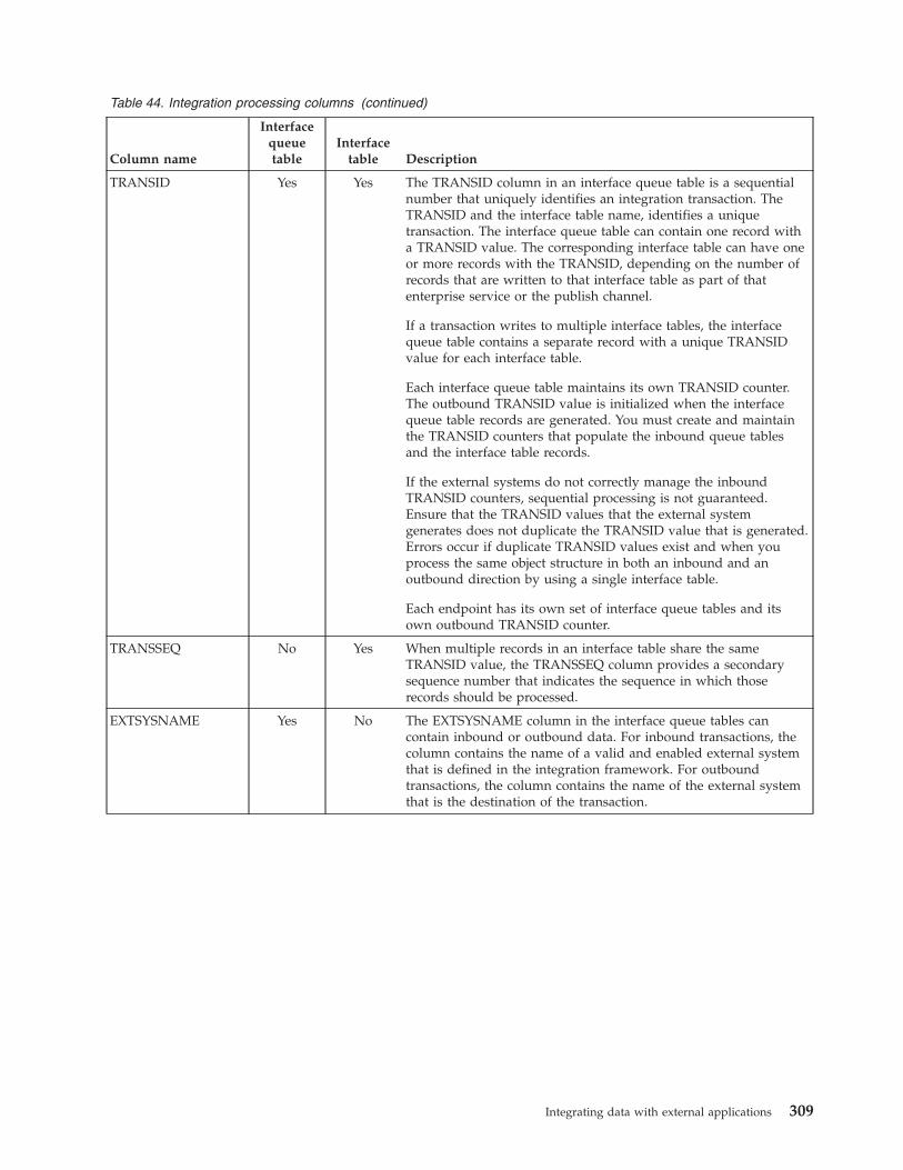
Table 44. Integration processing columns (continued)
Column name
Interfacequeuetable
Interfacetable Description
TRANSID Yes Yes The TRANSID column in an interface queue table is a sequentialnumber that uniquely identifies an integration transaction. TheTRANSID and the interface table name, identifies a uniquetransaction. The interface queue table can contain one record witha TRANSID value. The corresponding interface table can have oneor more records with the TRANSID, depending on the number ofrecords that are written to that interface table as part of thatenterprise service or the publish channel.
If a transaction writes to multiple interface tables, the interfacequeue table contains a separate record with a unique TRANSIDvalue for each interface table.
Each interface queue table maintains its own TRANSID counter.The outbound TRANSID value is initialized when the interfacequeue table records are generated. You must create and maintainthe TRANSID counters that populate the inbound queue tablesand the interface table records.
If the external systems do not correctly manage the inboundTRANSID counters, sequential processing is not guaranteed.Ensure that the TRANSID values that the external systemgenerates does not duplicate the TRANSID value that is generated.Errors occur if duplicate TRANSID values exist and when youprocess the same object structure in both an inbound and anoutbound direction by using a single interface table.
Each endpoint has its own set of interface queue tables and itsown outbound TRANSID counter.
TRANSSEQ No Yes When multiple records in an interface table share the sameTRANSID value, the TRANSSEQ column provides a secondarysequence number that indicates the sequence in which thoserecords should be processed.
EXTSYSNAME Yes No The EXTSYSNAME column in the interface queue tables cancontain inbound or outbound data. For inbound transactions, thecolumn contains the name of a valid and enabled external systemthat is defined in the integration framework. For outboundtransactions, the column contains the name of the external systemthat is the destination of the transaction.
Integrating data with external applications 309
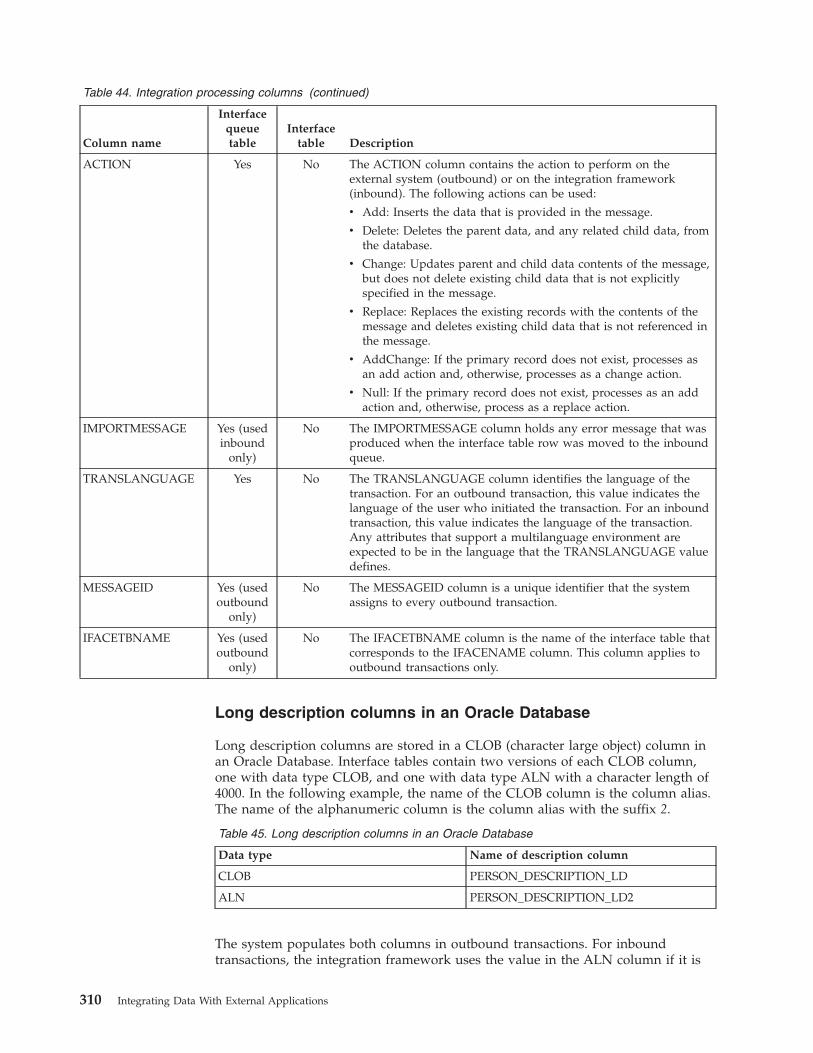
Table 44. Integration processing columns (continued)
Column name
Interfacequeuetable
Interfacetable Description
ACTION Yes No The ACTION column contains the action to perform on theexternal system (outbound) or on the integration framework(inbound). The following actions can be used:
v Add: Inserts the data that is provided in the message.
v Delete: Deletes the parent data, and any related child data, fromthe database.
v Change: Updates parent and child data contents of the message,but does not delete existing child data that is not explicitlyspecified in the message.
v Replace: Replaces the existing records with the contents of themessage and deletes existing child data that is not referenced inthe message.
v AddChange: If the primary record does not exist, processes asan add action and, otherwise, processes as a change action.
v Null: If the primary record does not exist, processes as an addaction and, otherwise, process as a replace action.
IMPORTMESSAGE Yes (usedinbound
only)
No The IMPORTMESSAGE column holds any error message that wasproduced when the interface table row was moved to the inboundqueue.
TRANSLANGUAGE Yes No The TRANSLANGUAGE column identifies the language of thetransaction. For an outbound transaction, this value indicates thelanguage of the user who initiated the transaction. For an inboundtransaction, this value indicates the language of the transaction.Any attributes that support a multilanguage environment areexpected to be in the language that the TRANSLANGUAGE valuedefines.
MESSAGEID Yes (usedoutbound
only)
No The MESSAGEID column is a unique identifier that the systemassigns to every outbound transaction.
IFACETBNAME Yes (usedoutbound
only)
No The IFACETBNAME column is the name of the interface table thatcorresponds to the IFACENAME column. This column applies tooutbound transactions only.
Long description columns in an Oracle Database
Long description columns are stored in a CLOB (character large object) column inan Oracle Database. Interface tables contain two versions of each CLOB column,one with data type CLOB, and one with data type ALN with a character length of4000. In the following example, the name of the CLOB column is the column alias.The name of the alphanumeric column is the column alias with the suffix 2.
Table 45. Long description columns in an Oracle Database
Data type Name of description column
CLOB PERSON_DESCRIPTION_LD
ALN PERSON_DESCRIPTION_LD2
The system populates both columns in outbound transactions. For inboundtransactions, the integration framework uses the value in the ALN column if it is
310 Integrating Data With External Applications
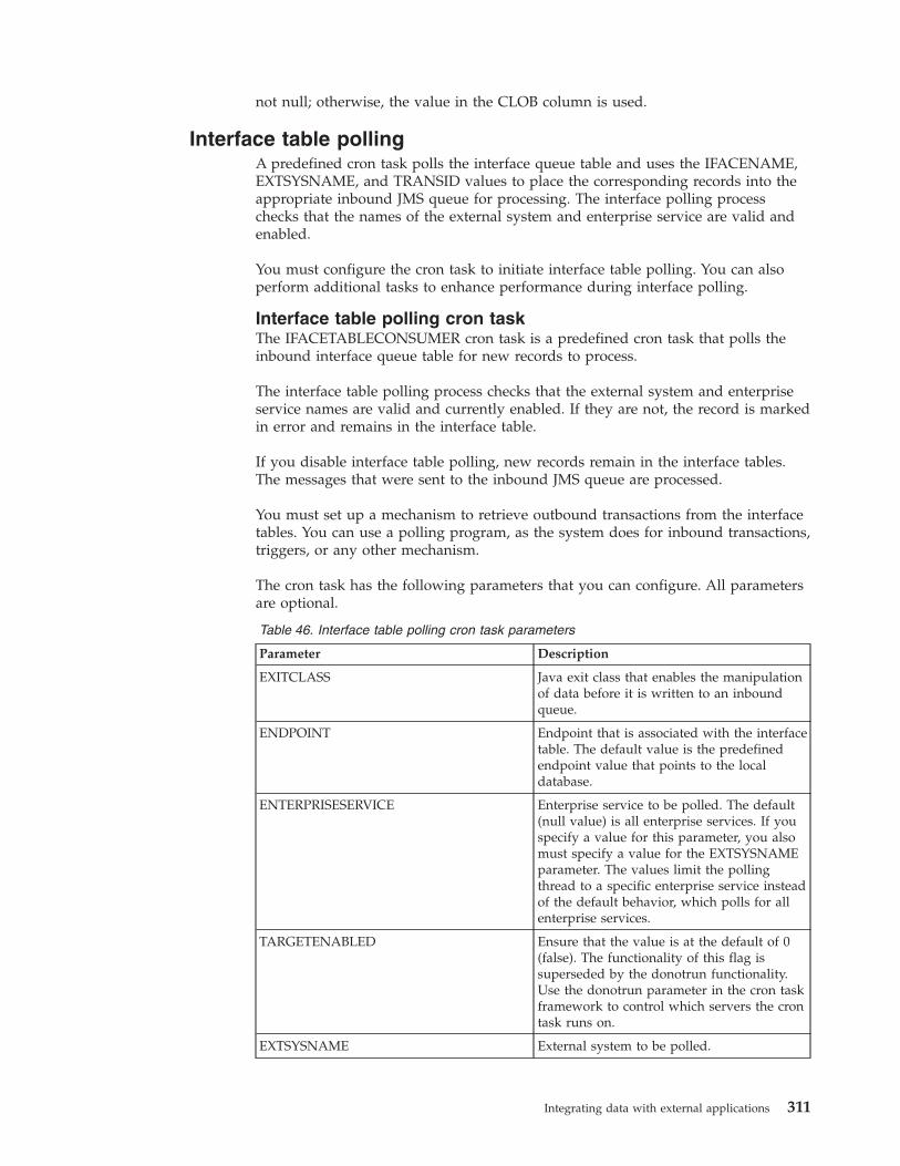
not null; otherwise, the value in the CLOB column is used.
Interface table pollingA predefined cron task polls the interface queue table and uses the IFACENAME,EXTSYSNAME, and TRANSID values to place the corresponding records into theappropriate inbound JMS queue for processing. The interface polling processchecks that the names of the external system and enterprise service are valid andenabled.
You must configure the cron task to initiate interface table polling. You can alsoperform additional tasks to enhance performance during interface polling.
Interface table polling cron taskThe IFACETABLECONSUMER cron task is a predefined cron task that polls theinbound interface queue table for new records to process.
The interface table polling process checks that the external system and enterpriseservice names are valid and currently enabled. If they are not, the record is markedin error and remains in the interface table.
If you disable interface table polling, new records remain in the interface tables.The messages that were sent to the inbound JMS queue are processed.
You must set up a mechanism to retrieve outbound transactions from the interfacetables. You can use a polling program, as the system does for inbound transactions,triggers, or any other mechanism.
The cron task has the following parameters that you can configure. All parametersare optional.
Table 46. Interface table polling cron task parameters
Parameter Description
EXITCLASS Java exit class that enables the manipulationof data before it is written to an inboundqueue.
ENDPOINT Endpoint that is associated with the interfacetable. The default value is the predefinedendpoint value that points to the localdatabase.
ENTERPRISESERVICE Enterprise service to be polled. The default(null value) is all enterprise services. If youspecify a value for this parameter, you alsomust specify a value for the EXTSYSNAMEparameter. The values limit the pollingthread to a specific enterprise service insteadof the default behavior, which polls for allenterprise services.
TARGETENABLED Ensure that the value is at the default of 0(false). The functionality of this flag issuperseded by the donotrun functionality.Use the donotrun parameter in the cron taskframework to control which servers the crontask runs on.
EXTSYSNAME External system to be polled.
Integrating data with external applications 311
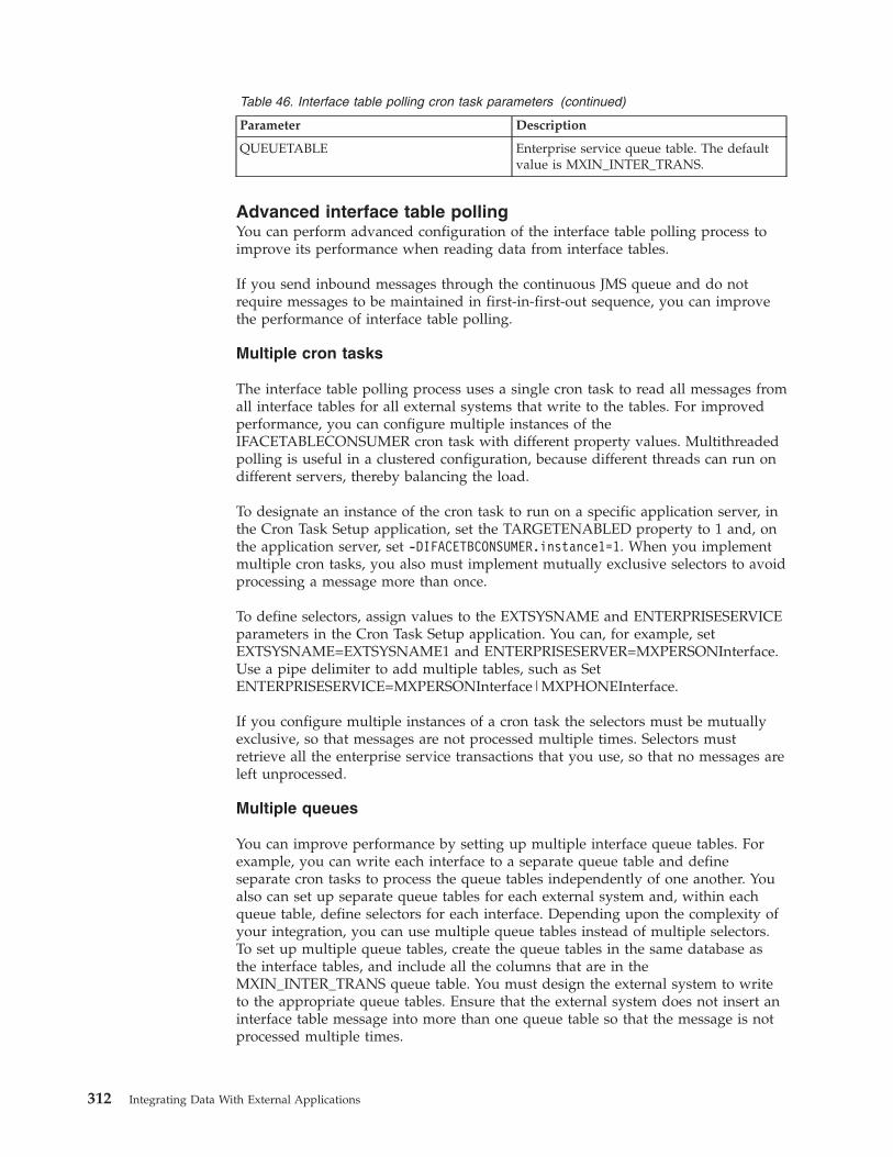
Table 46. Interface table polling cron task parameters (continued)
Parameter Description
QUEUETABLE Enterprise service queue table. The defaultvalue is MXIN_INTER_TRANS.
Advanced interface table pollingYou can perform advanced configuration of the interface table polling process toimprove its performance when reading data from interface tables.
If you send inbound messages through the continuous JMS queue and do notrequire messages to be maintained in first-in-first-out sequence, you can improvethe performance of interface table polling.
Multiple cron tasks
The interface table polling process uses a single cron task to read all messages fromall interface tables for all external systems that write to the tables. For improvedperformance, you can configure multiple instances of theIFACETABLECONSUMER cron task with different property values. Multithreadedpolling is useful in a clustered configuration, because different threads can run ondifferent servers, thereby balancing the load.
To designate an instance of the cron task to run on a specific application server, inthe Cron Task Setup application, set the TARGETENABLED property to 1 and, onthe application server, set -DIFACETBCONSUMER.instance1=1. When you implementmultiple cron tasks, you also must implement mutually exclusive selectors to avoidprocessing a message more than once.
To define selectors, assign values to the EXTSYSNAME and ENTERPRISESERVICEparameters in the Cron Task Setup application. You can, for example, setEXTSYSNAME=EXTSYSNAME1 and ENTERPRISESERVER=MXPERSONInterface.Use a pipe delimiter to add multiple tables, such as SetENTERPRISESERVICE=MXPERSONInterface|MXPHONEInterface.
If you configure multiple instances of a cron task the selectors must be mutuallyexclusive, so that messages are not processed multiple times. Selectors mustretrieve all the enterprise service transactions that you use, so that no messages areleft unprocessed.
Multiple queues
You can improve performance by setting up multiple interface queue tables. Forexample, you can write each interface to a separate queue table and defineseparate cron tasks to process the queue tables independently of one another. Youalso can set up separate queue tables for each external system and, within eachqueue table, define selectors for each interface. Depending upon the complexity ofyour integration, you can use multiple queue tables instead of multiple selectors.To set up multiple queue tables, create the queue tables in the same database asthe interface tables, and include all the columns that are in theMXIN_INTER_TRANS queue table. You must design the external system to writeto the appropriate queue tables. Ensure that the external system does not insert aninterface table message into more than one queue table so that the message is notprocessed multiple times.
312 Integrating Data With External Applications
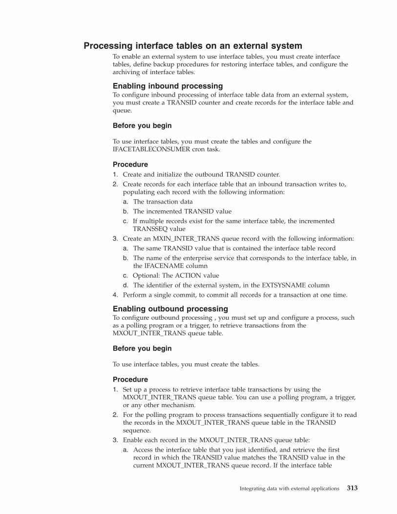
Processing interface tables on an external systemTo enable an external system to use interface tables, you must create interfacetables, define backup procedures for restoring interface tables, and configure thearchiving of interface tables.
Enabling inbound processingTo configure inbound processing of interface table data from an external system,you must create a TRANSID counter and create records for the interface table andqueue.
Before you begin
To use interface tables, you must create the tables and configure theIFACETABLECONSUMER cron task.
Procedure1. Create and initialize the outbound TRANSID counter.2. Create records for each interface table that an inbound transaction writes to,
populating each record with the following information:a. The transaction datab. The incremented TRANSID valuec. If multiple records exist for the same interface table, the incremented
TRANSSEQ value3. Create an MXIN_INTER_TRANS queue record with the following information:
a. The same TRANSID value that is contained the interface table recordb. The name of the enterprise service that corresponds to the interface table, in
the IFACENAME columnc. Optional: The ACTION valued. The identifier of the external system, in the EXTSYSNAME column
4. Perform a single commit, to commit all records for a transaction at one time.
Enabling outbound processingTo configure outbound processing , you must set up and configure a process, suchas a polling program or a trigger, to retrieve transactions from theMXOUT_INTER_TRANS queue table.
Before you begin
To use interface tables, you must create the tables.
Procedure1. Set up a process to retrieve interface table transactions by using the
MXOUT_INTER_TRANS queue table. You can use a polling program, a trigger,or any other mechanism.
2. For the polling program to process transactions sequentially configure it to readthe records in the MXOUT_INTER_TRANS queue table in the TRANSIDsequence.
3. Enable each record in the MXOUT_INTER_TRANS queue table:a. Access the interface table that you just identified, and retrieve the first
record in which the TRANSID value matches the TRANSID value in thecurrent MXOUT_INTER_TRANS queue record. If the interface table
Integrating data with external applications 313
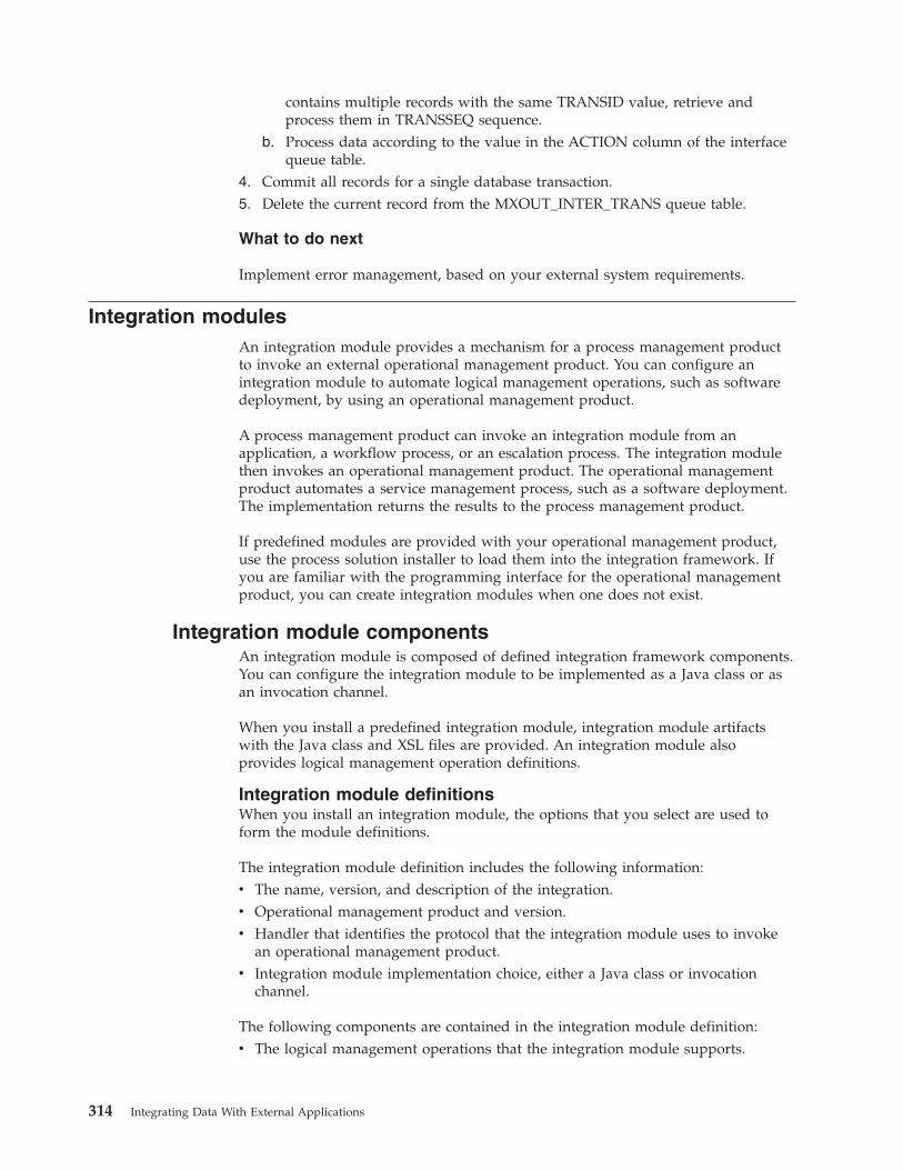
contains multiple records with the same TRANSID value, retrieve andprocess them in TRANSSEQ sequence.
b. Process data according to the value in the ACTION column of the interfacequeue table.
4. Commit all records for a single database transaction.5. Delete the current record from the MXOUT_INTER_TRANS queue table.
What to do next
Implement error management, based on your external system requirements.
Integration modulesAn integration module provides a mechanism for a process management productto invoke an external operational management product. You can configure anintegration module to automate logical management operations, such as softwaredeployment, by using an operational management product.
A process management product can invoke an integration module from anapplication, a workflow process, or an escalation process. The integration modulethen invokes an operational management product. The operational managementproduct automates a service management process, such as a software deployment.The implementation returns the results to the process management product.
If predefined modules are provided with your operational management product,use the process solution installer to load them into the integration framework. Ifyou are familiar with the programming interface for the operational managementproduct, you can create integration modules when one does not exist.
Integration module componentsAn integration module is composed of defined integration framework components.You can configure the integration module to be implemented as a Java class or asan invocation channel.
When you install a predefined integration module, integration module artifactswith the Java class and XSL files are provided. An integration module alsoprovides logical management operation definitions.
Integration module definitionsWhen you install an integration module, the options that you select are used toform the module definitions.
The integration module definition includes the following information:v The name, version, and description of the integration.v Operational management product and version.v Handler that identifies the protocol that the integration module uses to invoke
an operational management product.v Integration module implementation choice, either a Java class or invocation
channel.
The following components are contained in the integration module definition:v The logical management operations that the integration module supports.
314 Integrating Data With External Applications
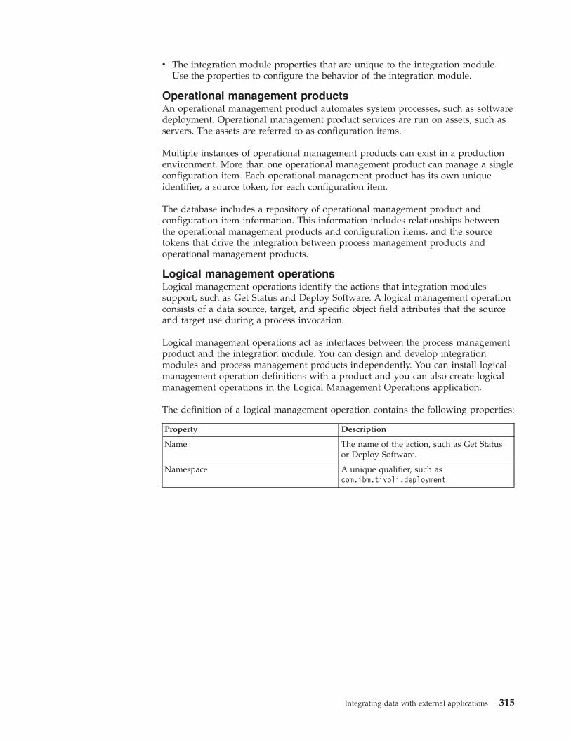
v The integration module properties that are unique to the integration module.Use the properties to configure the behavior of the integration module.
Operational management productsAn operational management product automates system processes, such as softwaredeployment. Operational management product services are run on assets, such asservers. The assets are referred to as configuration items.
Multiple instances of operational management products can exist in a productionenvironment. More than one operational management product can manage a singleconfiguration item. Each operational management product has its own uniqueidentifier, a source token, for each configuration item.
The database includes a repository of operational management product andconfiguration item information. This information includes relationships betweenthe operational management products and configuration items, and the sourcetokens that drive the integration between process management products andoperational management products.
Logical management operationsLogical management operations identify the actions that integration modulessupport, such as Get Status and Deploy Software. A logical management operationconsists of a data source, target, and specific object field attributes that the sourceand target use during a process invocation.
Logical management operations act as interfaces between the process managementproduct and the integration module. You can design and develop integrationmodules and process management products independently. You can install logicalmanagement operation definitions with a product and you can also create logicalmanagement operations in the Logical Management Operations application.
The definition of a logical management operation contains the following properties:
Property Description
Name The name of the action, such as Get Statusor Deploy Software.
Namespace A unique qualifier, such ascom.ibm.tivoli.deployment.
Integrating data with external applications 315
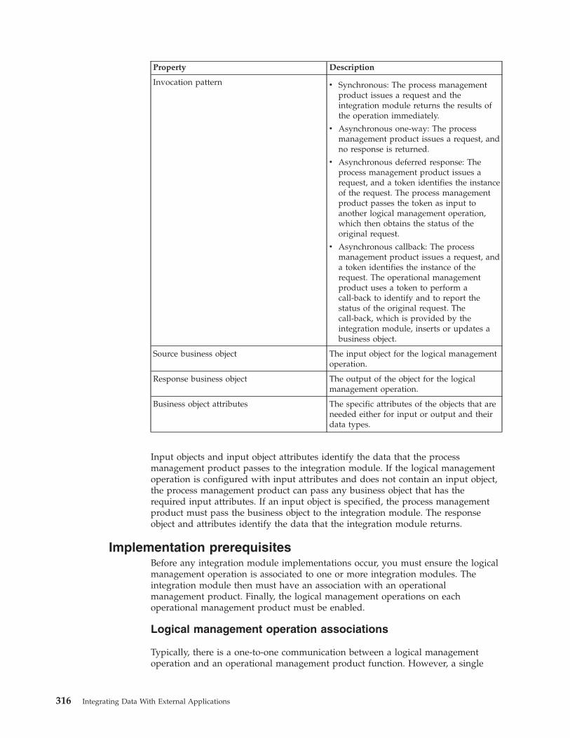
Property Description
Invocation pattern v Synchronous: The process managementproduct issues a request and theintegration module returns the results ofthe operation immediately.
v Asynchronous one-way: The processmanagement product issues a request, andno response is returned.
v Asynchronous deferred response: Theprocess management product issues arequest, and a token identifies the instanceof the request. The process managementproduct passes the token as input toanother logical management operation,which then obtains the status of theoriginal request.
v Asynchronous callback: The processmanagement product issues a request, anda token identifies the instance of therequest. The operational managementproduct uses a token to perform acall-back to identify and to report thestatus of the original request. Thecall-back, which is provided by theintegration module, inserts or updates abusiness object.
Source business object The input object for the logical managementoperation.
Response business object The output of the object for the logicalmanagement operation.
Business object attributes The specific attributes of the objects that areneeded either for input or output and theirdata types.
Input objects and input object attributes identify the data that the processmanagement product passes to the integration module. If the logical managementoperation is configured with input attributes and does not contain an input object,the process management product can pass any business object that has therequired input attributes. If an input object is specified, the process managementproduct must pass the business object to the integration module. The responseobject and attributes identify the data that the integration module returns.
Implementation prerequisitesBefore any integration module implementations occur, you must ensure the logicalmanagement operation is associated to one or more integration modules. Theintegration module then must have an association with an operationalmanagement product. Finally, the logical management operations on eachoperational management product must be enabled.
Logical management operation associations
Typically, there is a one-to-one communication between a logical managementoperation and an operational management product function. However, a single
316 Integrating Data With External Applications
logical management operation invocation can cause the integration module toinvoke an operational management product multiple times.
An integration module that uses an invocation channel can run logicalmanagement operations only in the following circumstances:v The source object that is defined on the logical management operation must
match the main object of the request object structure that you define on theinvocation channel.
v If the invocation channel is not configured to process a response, you cannotassociate a response object with the logical management operation.
v The response object that you define on the logical management operation mustmatch the main object of the response object structure that you define on theinvocation channel. The match must occur when you configure the invocationchannel to process a response.
Operational management product associations
The integration module can support multiple logical management operations foran operational management product. When you run the integration module, thename and namespace values of the logical management operation specify theaction to perform.
Operational management product and integration module associations are createdwhen the OMPPRODUCTNAME and OMPVERSION values are added to theintegration module. If multiple versions of the operational management productare used with the integration module, use a null value for the OMPVERSION.
Logical operation management enablement
More than one integration module can implement the same logical managementoperation on an operational management product. Use the ISPRIMARY attribute toidentify the preferred integration module for the logical management operation onthe operational management product. Only one integration module can have theISPRIMARY value set to a true for any given logical management operation -operational management product combination.
Implementation propertiesThe integration framework can automatically process integration data when youimplement an integration module. You can customize the implementation if youwant to bypass parts of the automatic process.
Integration module parametersThe integration framework provides integration module input parameters,including source and response objects and object sets, and endpoint names. Theseparameters are passed when you run an integration module as a Java class or asan invocation channel.
The following table lists the psdi.iface.omp.IMConstants interface parameters andtheir names.
Name Description
IM The instantiated ServiceInvoker object whichcan be a Java integration module or aninvocation channel.
Integrating data with external applications 317
Name Description
IMNAME The name of the integration module.
IMVERSION The version of the integration module.
LMONAME The name of the logical managementoperation that is invoked.
LMONAMESPACE The name space of the logical managementoperation that is invoked.
OMPGUID The globally unique identifier (GUID) of theoperational management product that theintegration module uses.
ENDPOINTNAME The name of the endpoint that theintegration module uses to communicatewith the operational management product.
ENDPOINTPROP A map ofString.psdi.iface.mic.MaxEndPointPropInfoproperties that override the endpointproperties.
USERNAME The user name that the integrationframework uses to communicate with theendpoint.
PASSWORD The password for USERNAME.
Integration module process flowJava-based integration modules populate the logical management operationresponse object or response object set with the results of the operation. Forinvocation channels, you can specify a mapping from the operational managementproduct response to the response object or set. The integration framework copiesthe data into the response object or set.
Integration modules must quickly return to their callers. If the external service is along-running service, the integration module must create another thread. The newthread makes the call to the operational management product, while the originalthread returns to the caller.
Integration modules perform the following processing tasks:1. Retrieve input from the source object or source object set.2. If applicable, retrieve the integration module-specific properties.3. Perform all processing logic that the logical management operation requires
before it calls the operational management product.4. Call the operational management product.5. If applicable, handle the operational management product response.6. If applicable, populate the response object or response object set with the return
data.7. Return processing information back to the caller.
EndpointsAn integration module that contains an invocation channel must use an endpoint.A Java class integration module can use an endpoint or use a custom approach toexternal service invocations.
318 Integrating Data With External Applications
Endpoints contain URL properties and handler properties that specify the transportmechanism to use. An endpoint with a web service handler has different propertiesthan an endpoint with a command-line handler. Integration module endpoints andendpoint properties can be overwritten at run time when the process managementproduct passes endpoint properties as input to the integration module. TheUSERNAME and PASSWORD properties that are returned from the credentialmapper can also override the endpoint properties.
Java integration modules can communicate directly with an operationalmanagement product or external integration module, without the use of anendpoint. If you do not use an endpoint, you eliminate the need for the Javaintegration module to convert source objects into the required XML format. Whenyou exclude endpoint use, you can use any communication protocol that issupported by the operational management product. Integration modules are notrequired to use endpoints. You can configure the integration module tocommunicate with an operational management product by using integrationmodule properties.
The integration framework provides predefined handlers that supportcommunication protocols such as HTTP and web services. If a predefined handleris not available to support the operational management product service protocol,implement an external integration module. The external integration module acts asan interface to the operational management product service that can use one of theavailable handler protocols. An alternative solution is to write a custom handlerthat supports the operational management product service protocol.
Configure a different endpoint for each operational management product toestablish individual protocols for each product. The handler that you define for theendpoint must match the handler that you configure for the integration module.
Integration modules based on invocation channels require an endpoint. Theendpoint name is one of the parameters the integration framework passes as inputto the invocation channel. The caller of the integration module can override theendpoint name.
Regardless of whether you use an endpoint handler to communicate with theoperational management product, the integration module must handle scenariosthat require multiple invocations of the operational management product for asingle logical management operation execution.
Invocation channel or Java class implementationYou can implement an integration module either as a Java class or as an invocationchannel. Before developing an integration module, review the advantages anddisadvantages to invocation channel or Java class usage.
Invocation channel and Java class comparisonBefore you develop an integration module, consider the advantages anddisadvantages of using a Java class or an invocation channel.
Advantages and disadvantages of using an invocation channel
Implementing an integration module by using an invocation channel has thefollowing advantages:
Integrating data with external applications 319
v An invocation channel is useful when you pass complex data to the endpoint. Itis also useful when you can define a clear mapping between the fields in thesource object and the input the endpoint requires.
v Can support hierarchical object structures on input and output transactions.v The integration framework handles the conversion of objects to XML, and XML
to objects.v Can be configured to use processing classes, user exits, and XSL mapping for
inbound and outbound transactions.v The integration framework performs endpoint invocation.v Can be invoked directly without an association to an integration module or a
logical management operation.v A simple integration can be implemented using system configuration that does
not require you to restart the application server.
Implementing an integration module by using an invocation channel has thefollowing disadvantages:v Requires more registration and configuration of system artifacts, even when the
invocation is simple.v Multiple applications cannot use the integration module with different business
objects.v Requires additional knowledge of the integration framework.v Supports only a single invocation of the configured endpoint. It requires
additional coding to support multiple invocations.v Requires additional coding to support a long-running service. By default, the
invocation channel waits for a response from the endpoint.
Advantages and disadvantages of using a Java class
Implementing an integration module by using a Java class has the followingadvantages:v Requires less registration and configuration of system artifacts.v Can be used by different applications while using different business objects.v Can be designed to make multiple external invocations.v Can use different communication protocols for different logical management
operations and operational management products.v Supports the use of another thread to accommodate a long-running service.v Can implement multiple logical management operations, even when the input
configuration and the output configuration is different.v Is less likely to require the use of an external integration module.
Implementing an integration module by using a Java class has the followingdisadvantages:v Requires you to perform more Java coding.v Does not support an object structure with a parent and child relationship as
input or output. Only the parent object can be used as input, and the Java codemust find the child relationship.
v Conversions of objects to XML and XML to objects must be coded when you usean endpoint handler.
v Customization must be built into the design of the integration module.Customization cannot be added later without redeploying the code.
320 Integrating Data With External Applications
v Use of any integration framework components, such as an endpoint handler,must be coded in the Java class.
Invocation channel implementationInvocation channels use object structures in its implementations to expand themessage data content. The object structure uses the object that the processmanagement product passes as the source object to build an entire record that canconsist of multiple related objects.
The objects that are identified in the object structures are used in the XML messagecreation. When you use an invocation channel, the data must conform to the XMLschemas specified for the associated object structures, and you must define anendpoint for the invocation channel.
Invocation channels support optional inbound and outbound processing exitclasses. The integration framework uses processing exit classes to implementadditional logic. The inbound and outbound processing exit classes must beinstances of the Java class psdi.iface.migexits.ExternalExit.
For outbound transactions, the integration framework calls the following method:public StructureData setDataOut(StructureData irData)
For inbound transactions, the integration framework calls the following method:public StructureData setDataIn(StructureData erData)
When you override these methods, you can perform additional integration moduleprocessing. The properties that are passed to the invocation channel are availableto the processing classes.
The following outbound processing class code shows you how to retrieve theoperational management product globally unique identifier when you run aninvocation channel:import psdi.server.MXServer;import psdi.iface.omp.IMConstants;import psdi.iface.omp.OmpServiceRemote;import psdi.iface.mic.*;import psdi.iface.migexits.*;...public class OutboundCIExit extends ExternalExit implements IMConstants{public StructureData setDataOut(StructureData irData)throws MXException, RemoteException{IntegrationContext cntx = IntegrationContext.getCurrentContext();String ompGUID = cntx.getStringProperty(OMPGUID);...
}}
Additional features of the invocation channel include user exit Java classes and anXSL mapping layer. You can configure the XSL mapping layer to do XML mappingor data transformation.
Integrating data with external applications 321
If the object structure that you need for your integration module invocation doesnot exist, you can create an object structure in the Object Structures application.You also can use XML with the MXINTOBJECT object structure to create objectstructures as part of the installation process.
Java class implementationIntegration modules can be implemented to use Java class files. Using a Java classfile eliminates the need for integration component registration and configuration.Additionally, all the underlying integration module implementations aretransparent to the process management product.
Java class integration modules must implement thepsdi.iface.mic.ServiceInvoker Java interface. The service invoker Java interface isincluded in the businessobjects.jar file. Include the integration module Java classin the system class path at run time.
The service invoker Java interface has variations of the following methodsignature:
public byte[] invoke(Map String,Object metaData, MboRemote sourceMbo,MboRemote targetMbo, String endPointName) throws MXException,RemoteException;
v metaData is a map of the name and value properties that includes:– The integration module name and version.– The logical management operation name and name space.– The operational management product globally unique identifier.– The endpoint name and any endpoint properties that are being overwritten.
v sourceMbo is the source object that you defined on the logical managementoperation.
v targetMbo is the response object that you defined on the logical managementoperation
v endPointName is the name of the endpoint that you use for communication withthe operational management product.
If you configure the integration module to implement multiple logical managementoperations, the integration module must determine which logical managementoperation is being called. At run time, the integration module retrieves theLMONAME and LMONAMESPACE properties from the metaData input map:import psdi.iface.omp.IMConstants;...String lmoName = metaData.get(IMConstants.LMONAME);String lmoNamespace = metaData.get(IMConstants.LMONAMESPACE);
The integration module can retrieve logical management operation data from thesource object. The following example code retrieves logical management operationvalues from the source object:String guid = sourceMbo.getString("GUID");int packID = sourceMbo.getInt("PACKID");boolean hasSubs = sourceMbo.getBoolean("HASSUBS");
In the example, the logical management operation has an alphanumeric inputattribute called globally unique identifier, an integer attribute called PACKID, anda Boolean attribute called HASSUBS.
322 Integrating Data With External Applications
Service invoker methods can take a MboSetRemote set of values as a source input,instead of a single MboRemote value. In some cases, the integration module passesall of the objects in the object set to the operational management product. In othercases, the integration module passes only the first object in the set. There are no setrules that apply to the integration module behavior, but you must clearly definethe expected behavior in the logical management operation description.
Integration module processingProcess management products use a system action to initiate an integrationmodule. The action can be associated with an escalation or a workflow, or can beinitiated from a menu or a button. The process management product provides anaction class that invokes the integration module and processes the response thatthe integration module returns.
Identification of integration componentsThe initiation action class identifies the components required for the integration,including the logical management operation, the operational management product,and the integration module.
The logical management operation runs a process, such as software deployment,on a configuration item by using an operational management product. The processmanagement product provides the necessary input to the integration module,based on the input business objects and attributes that are defined on the logicalmanagement operation.
The Java action class identifies an operational management product that runs thelogical management operation on the selected configuration item. When you installconfiguration items and operational management products, the componentrelationships are also installed.
An integration module record identifies which logical management operations aresupported on an operational management product. When the integration modules,configuration items, and operational management products are registered, theprocess management product Java class performs a lookup. The Java classdetermines which integration modules that it invokes based on the configurationitems that it uses.
The integration framework includes a service that provides the following utilitymethods to assist the class with integration module lookups.
Utility method Function
psdi.iface.app.omp.OmpSetRemote getOMPListForIM(String imName, String imVersion)
Retrieves a list of the operational management productsthat are associated with the integration module.
psdi.iface.app.im.MaxIMSetRemote getIMListForLMO(String lmoName, String lmoNamespace)
Retrieves a list of the integration modules thatimplement the specified logical management operation.
psdi.iface.app.im.MaxIMSetRemotegetIMListForLMOWithOMP (String lmoName, StringlmoNamespace)
Retrieves a list of the integration modules thatimplement the specified logical management operationon any operational management products.
psdi.iface.app.im.MaxIMSetRemote getIMListForOMP(String ompGuid)
Retrieves the list of the integration modules thatimplement at least one logical management operation onthe operational management product.
Integrating data with external applications 323
Utility method Function
Collection getIMListForOMPAndLMO (String ompGUID,String lmoName, String lmoNamespace)
Retrieves the list of integration modules that implementthe logical management operation on the specifiedoperational management product.
Returns a collection of psdi.iface.omp.OmpImLmoRelInfoobjects.
Collection getIMListForOMPAndLMO (String ompHostname,String ompProductname, String ompManufacturer,String lmoName, String lmoNamespace)
Retrieves the list of integration modules that implementthe logical management operation on the specifiedoperational management products.
Returns a collection of psdi.iface.omp.OmpImLmoRelInfoobjects.
psdi.iface.omp.OmpImLmoRelInfo getPreferredIM(String ompGUID, String lmoName, StringlmoNamespace)
Retrieves the preferred integration module thatimplements the logical management operation on thespecified operational management product.
psdi.iface.omp.OmpImLmoRelInfo getPreferredIM(String ompHostname, String ompProductname, StringompManufacturer, String lmoName, StringlmoNamespace)
Retrieves the preferred integration module thatimplements the logical management operation on thespecified operational management product.
Integration module invocationIntegration modules can be implemented either as Java classes or as invocationchannels. Integration module instances are called service invokers because theyimplement the Java interface psdi.iface.mic.ServiceInvoker.
The service invoker interface hides the underlying implementation from the caller.The invocation of the integration module by the caller is the same, regardless ofthe underlying implementation.
Service invoker property map:
The get service invoker utility methods return a map of name and value pairs.
The psdi.iface.omp.IMConstants Java interface defines the names of the propertiesthat are returned in the map. The property IMConstants.IM contains the instance ofthe integration module that the process management product invokes.
The property IMConstants.ENDPOINTNAME contains the name of the endpoint that isassociated with in the operational management product, integration module, andlogical management operation relationship. In most cases, the endpoint property isthe value that the process management product passes to the integration module.However, in unusual cases, the action class overwrites the configured endpoint.
If a credential mapper is configured, the get service invoker utility methods callthe credential mapper to retrieve the USERNAME and PASSWORD that is used forendpoint communication. These properties are returned by the utility methods in amap that is identified by the property IMConstants.ENDPOINTPROPS. The caller canoverwrite any endpoint properties by adding them to this map.
Before the action class calls the integration module, it must populate the sourceobject with the logical management operation input fields. The action class thenpasses the source object data to the integration module with the mapping that is
324 Integrating Data With External Applications
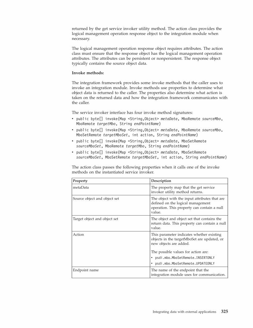
returned by the get service invoker utility method. The action class provides thelogical management operation response object to the integration module whennecessary.
The logical management operation response object requires attributes. The actionclass must ensure that the response object has the logical management operationattributes. The attributes can be persistent or nonpersistent. The response objecttypically contains the source object data.
Invoke methods:
The integration framework provides some invoke methods that the caller uses toinvoke an integration module. Invoke methods use properties to determine whatobject data is returned to the caller. The properties also determine what action istaken on the returned data and how the integration framework communicates withthe caller.
The service invoker interface has four invoke method signatures:v public byte[] invoke(Map <String,Object> metaData, MboRemote sourceMbo,
MboRemote targetMbo, String endPointName)
v public byte[] invoke(Map <String,Object> metaData, MboRemote sourceMbo,MboSetRemote targetMboSet, int action, String endPointName)
v public byte[] invoke(Map <String,Object> metaData, MboSetRemotesourceMboSet, MboRemote targetMbo, String endPointName)
v public byte[] invoke(Map <String,Object> metaData, MboSetRemotesourceMboSet, MboSetRemote targetMboSet, int action, String endPointName)
The action class passes the following properties when it calls one of the invokemethods on the instantiated service invoker.
Property Description
metaData The property map that the get serviceinvoker utility method returns.
Source object and object set The object with the input attributes that aredefined on the logical managementoperation. This property can contain a nullvalue.
Target object and object set The object and object set that contains thereturn data. This property can contain a nullvalue.
Action This parameter indicates whether existingobjects in the targetMboSet are updated, ornew objects are added.
The possible values for action are:
v psdi.mbo.MboSetRemote.INSERTONLY
v psdi.mbo.MboSetRemote.UPDATEONLY
Endpoint name The name of the endpoint that theintegration module uses for communication.
Integrating data with external applications 325
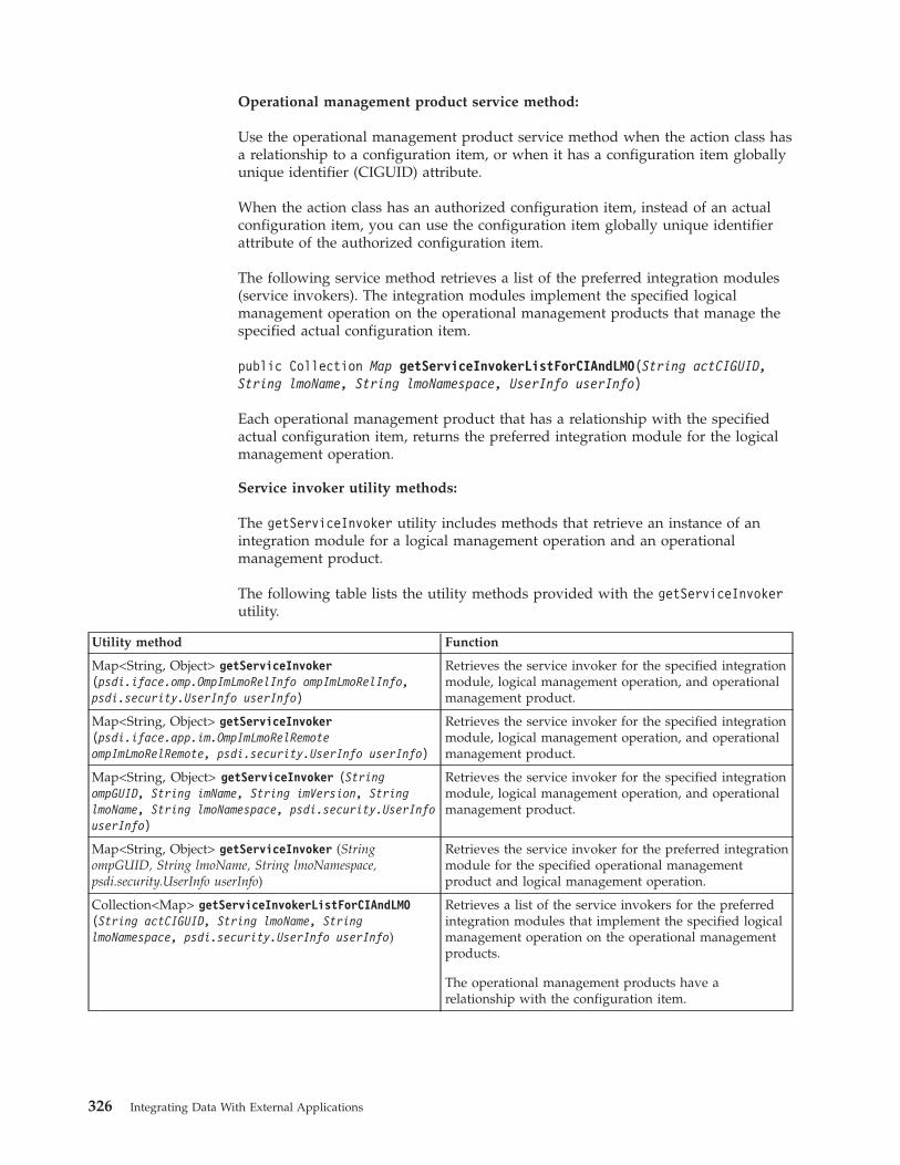
Operational management product service method:
Use the operational management product service method when the action class hasa relationship to a configuration item, or when it has a configuration item globallyunique identifier (CIGUID) attribute.
When the action class has an authorized configuration item, instead of an actualconfiguration item, you can use the configuration item globally unique identifierattribute of the authorized configuration item.
The following service method retrieves a list of the preferred integration modules(service invokers). The integration modules implement the specified logicalmanagement operation on the operational management products that manage thespecified actual configuration item.
public Collection Map getServiceInvokerListForCIAndLMO(String actCIGUID,String lmoName, String lmoNamespace, UserInfo userInfo)
Each operational management product that has a relationship with the specifiedactual configuration item, returns the preferred integration module for the logicalmanagement operation.
Service invoker utility methods:
The getServiceInvoker utility includes methods that retrieve an instance of anintegration module for a logical management operation and an operationalmanagement product.
The following table lists the utility methods provided with the getServiceInvokerutility.
Utility method Function
Map<String, Object> getServiceInvoker(psdi.iface.omp.OmpImLmoRelInfo ompImLmoRelInfo,psdi.security.UserInfo userInfo)
Retrieves the service invoker for the specified integrationmodule, logical management operation, and operationalmanagement product.
Map<String, Object> getServiceInvoker(psdi.iface.app.im.OmpImLmoRelRemoteompImLmoRelRemote, psdi.security.UserInfo userInfo)
Retrieves the service invoker for the specified integrationmodule, logical management operation, and operationalmanagement product.
Map<String, Object> getServiceInvoker (StringompGUID, String imName, String imVersion, StringlmoName, String lmoNamespace, psdi.security.UserInfouserInfo)
Retrieves the service invoker for the specified integrationmodule, logical management operation, and operationalmanagement product.
Map<String, Object> getServiceInvoker (StringompGUID, String lmoName, String lmoNamespace,psdi.security.UserInfo userInfo)
Retrieves the service invoker for the preferred integrationmodule for the specified operational managementproduct and logical management operation.
Collection<Map> getServiceInvokerListForCIAndLMO(String actCIGUID, String lmoName, StringlmoNamespace, psdi.security.UserInfo userInfo)
Retrieves a list of the service invokers for the preferredintegration modules that implement the specified logicalmanagement operation on the operational managementproducts.
The operational management products have arelationship with the configuration item.
326 Integrating Data With External Applications
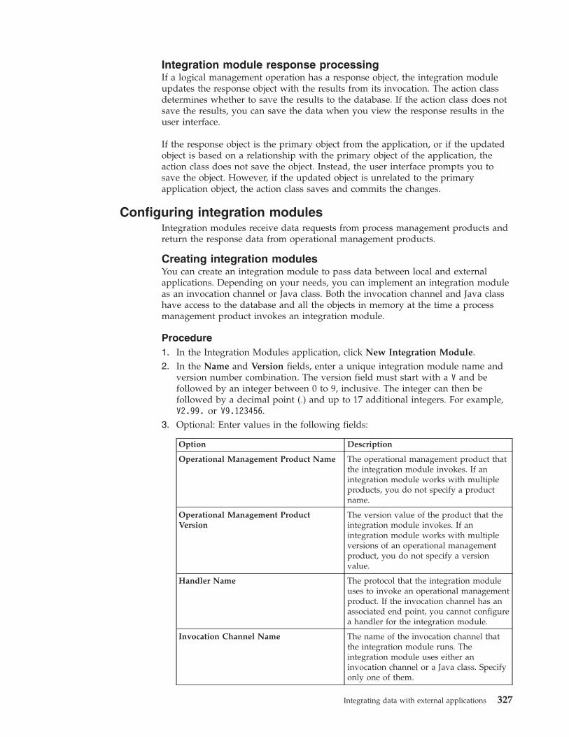
Integration module response processingIf a logical management operation has a response object, the integration moduleupdates the response object with the results from its invocation. The action classdetermines whether to save the results to the database. If the action class does notsave the results, you can save the data when you view the response results in theuser interface.
If the response object is the primary object from the application, or if the updatedobject is based on a relationship with the primary object of the application, theaction class does not save the object. Instead, the user interface prompts you tosave the object. However, if the updated object is unrelated to the primaryapplication object, the action class saves and commits the changes.
Configuring integration modulesIntegration modules receive data requests from process management products andreturn the response data from operational management products.
Creating integration modulesYou can create an integration module to pass data between local and externalapplications. Depending on your needs, you can implement an integration moduleas an invocation channel or Java class. Both the invocation channel and Java classhave access to the database and all the objects in memory at the time a processmanagement product invokes an integration module.
Procedure1. In the Integration Modules application, click New Integration Module.2. In the Name and Version fields, enter a unique integration module name and
version number combination. The version field must start with a V and befollowed by an integer between 0 to 9, inclusive. The integer can then befollowed by a decimal point (.) and up to 17 additional integers. For example,V2.99. or V9.123456.
3. Optional: Enter values in the following fields:
Option Description
Operational Management Product Name The operational management product thatthe integration module invokes. If anintegration module works with multipleproducts, you do not specify a productname.
Operational Management ProductVersion
The version value of the product that theintegration module invokes. If anintegration module works with multipleversions of an operational managementproduct, you do not specify a versionvalue.
Handler Name The protocol that the integration moduleuses to invoke an operational managementproduct. If the invocation channel has anassociated end point, you cannot configurea handler for the integration module.
Invocation Channel Name The name of the invocation channel thatthe integration module runs. Theintegration module uses either aninvocation channel or a Java class. Specifyonly one of them.
Integrating data with external applications 327
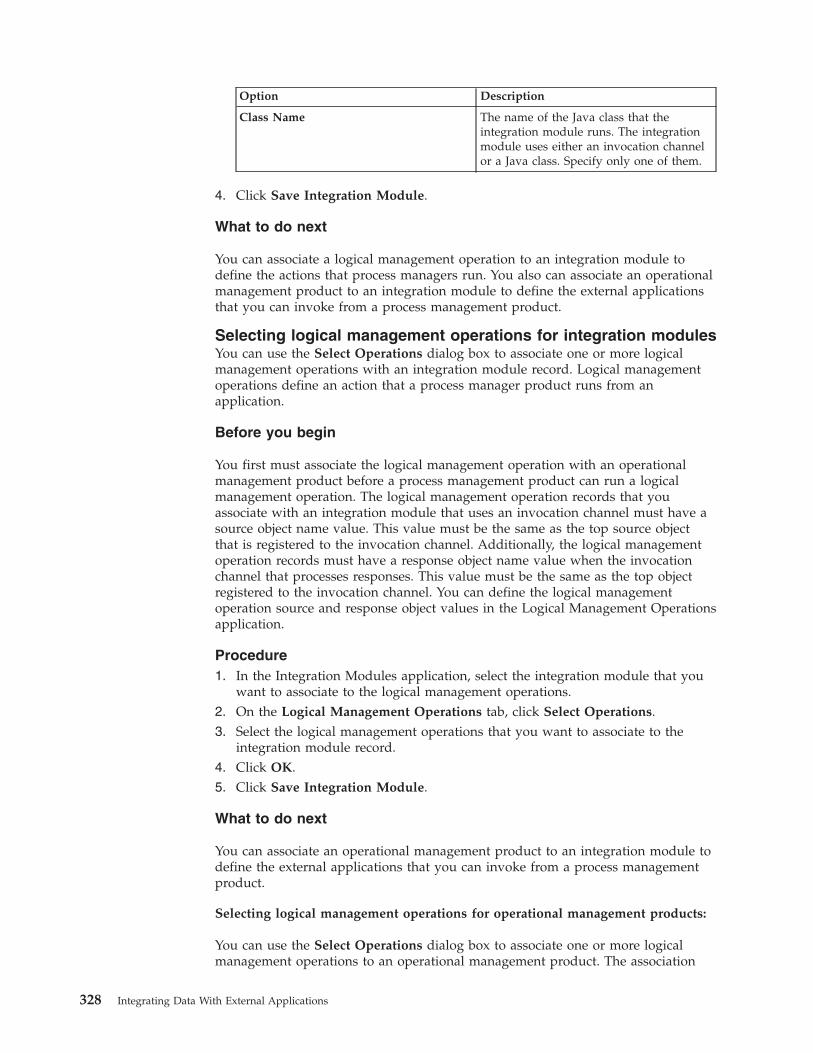
Option Description
Class Name The name of the Java class that theintegration module runs. The integrationmodule uses either an invocation channelor a Java class. Specify only one of them.
4. Click Save Integration Module.
What to do next
You can associate a logical management operation to an integration module todefine the actions that process managers run. You also can associate an operationalmanagement product to an integration module to define the external applicationsthat you can invoke from a process management product.
Selecting logical management operations for integration modulesYou can use the Select Operations dialog box to associate one or more logicalmanagement operations with an integration module record. Logical managementoperations define an action that a process manager product runs from anapplication.
Before you begin
You first must associate the logical management operation with an operationalmanagement product before a process management product can run a logicalmanagement operation. The logical management operation records that youassociate with an integration module that uses an invocation channel must have asource object name value. This value must be the same as the top source objectthat is registered to the invocation channel. Additionally, the logical managementoperation records must have a response object name value when the invocationchannel that processes responses. This value must be the same as the top objectregistered to the invocation channel. You can define the logical managementoperation source and response object values in the Logical Management Operationsapplication.
Procedure1. In the Integration Modules application, select the integration module that you
want to associate to the logical management operations.2. On the Logical Management Operations tab, click Select Operations.3. Select the logical management operations that you want to associate to the
integration module record.4. Click OK.5. Click Save Integration Module.
What to do next
You can associate an operational management product to an integration module todefine the external applications that you can invoke from a process managementproduct.
Selecting logical management operations for operational management products:
You can use the Select Operations dialog box to associate one or more logicalmanagement operations to an operational management product. The association
328 Integrating Data With External Applications
that you make to the operational management product enables the logicalmanagement operation. The enablement indicates that the logical managementoperation is ready for use.
Before you begin
A logical management operation must be associated with an integration modulebefore it can be enabled on an operational management product.
Procedure
1. In the Integration Modules application, select the integration module that youwant to associate to the logical management operations.
2. On the Operational Management Products subtab, select the operationalmanagement product that you want to associate to the logical managementoperations.
3. In the Logical Management Operations for Operational Management Producttable window, click Select Operations.
4. Select the logical management products that you want to enable for theoperational management product.
5. Click OK.6. Click Save Integration Module.
Associating a logical management operation with an integrationmoduleYou can associate a logical management operation with an integration module todefine the actions that are taken on an operational management product. Processmanagement products, such as Change or Deploy, call upon an integration moduleto run an operational management product. The operational management productthen runs the logical management product, such as deploy software, and notifiesthe process management product of the action status.
Before you begin
You first must associate the logical management operation with an operationalmanagement product before a process management product can run a logicalmanagement operation. The logical management operation records that youassociate with an integration module that uses an invocation channel must have asource object name value. This value must be the same as the top source objectthat is registered to the invocation channel. Additionally, the logical managementoperation records must have a response object name value when the invocationchannel that processes responses. This value must be the same as the top objectregistered to the invocation channel. You can define the logical managementoperation source and response object values in the Logical Management Operationsapplication.
About this task
The invocation pattern value determines whether the logical managementoperation is long-running. It also determines how the process management productexpects a response from the operational management product.
Procedure1. In the Integration Modules application, select the integration module that you
want to associate with a logical management operation.
Integrating data with external applications 329
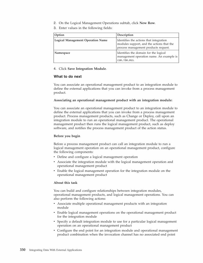
2. On the Logical Management Operations subtab, click New Row.3. Enter values in the following fields:
Option Description
Logical Management Operation Name Identifies the actions that integrationmodules support, and the actions that theprocess management products request.
Namespace Identifies the domain for the logicalmanagement operation name. An example iscom.ibm.mss.
4. Click Save Integration Module.
What to do next
You can associate an operational management product to an integration module todefine the external applications that you can invoke from a process managementproduct.
Associating an operational management product with an integration module:
You can associate an operational management product to an integration module todefine the external applications that you can invoke from a process managementproduct. Process management products, such as Change or Deploy, call upon anintegration module to run an operational management product. The operationalmanagement product then runs the logical management product, such as deploysoftware, and notifies the process management product of the action status.
Before you begin
Before a process management product can call an integration module to run alogical management operation on an operational management product, configurethe following components:v Define and configure a logical management operationv Associate the integration module with the logical management operation and
operational management productv Enable the logical management operation for the integration module on the
operational management product
About this task
You can build and configure relationships between integration modules,operational management products, and logical management operations. You canalso perform the following actions:v Associate multiple operational management products with an integration
modulev Enable logical management operations on the operational management product
for the integration modulev Specify a default integration module to use for a particular logical management
operation on an operational management productv Configure the end point for an integration module and operational management
product combination when the invocation channel has no associated end point
330 Integrating Data With External Applications
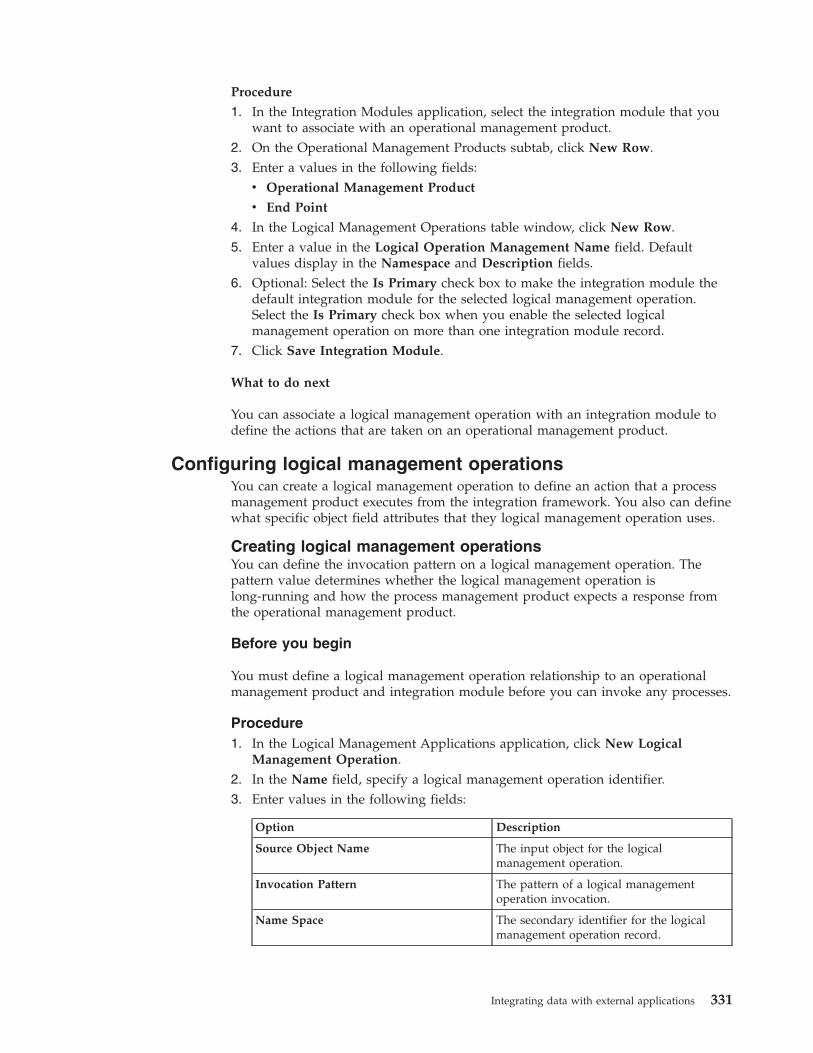
Procedure
1. In the Integration Modules application, select the integration module that youwant to associate with an operational management product.
2. On the Operational Management Products subtab, click New Row.3. Enter a values in the following fields:
v Operational Management Product
v End Point
4. In the Logical Management Operations table window, click New Row.5. Enter a value in the Logical Operation Management Name field. Default
values display in the Namespace and Description fields.6. Optional: Select the Is Primary check box to make the integration module the
default integration module for the selected logical management operation.Select the Is Primary check box when you enable the selected logicalmanagement operation on more than one integration module record.
7. Click Save Integration Module.
What to do next
You can associate a logical management operation with an integration module todefine the actions that are taken on an operational management product.
Configuring logical management operationsYou can create a logical management operation to define an action that a processmanagement product executes from the integration framework. You also can definewhat specific object field attributes that they logical management operation uses.
Creating logical management operationsYou can define the invocation pattern on a logical management operation. Thepattern value determines whether the logical management operation islong-running and how the process management product expects a response fromthe operational management product.
Before you begin
You must define a logical management operation relationship to an operationalmanagement product and integration module before you can invoke any processes.
Procedure1. In the Logical Management Applications application, click New Logical
Management Operation.2. In the Name field, specify a logical management operation identifier.3. Enter values in the following fields:
Option Description
Source Object Name The input object for the logicalmanagement operation.
Invocation Pattern The pattern of a logical managementoperation invocation.
Name Space The secondary identifier for the logicalmanagement operation record.
Integrating data with external applications 331
Option Description
Response Object Name The output of the object for the logicalmanagement operation.
4. Click Save Logical Management Operation.
Adding attributes to logical management operationsYou can add attributes to a logical management operation to identify the specificobject field attributes the logical management operation data source and target use.You can define the individual attribute entries for both input and output logicalmanagement operation invocations.
About this task
Input object attributes identify the data that the process management productpasses to the integration module. Output object attributes identify the data that theintegration module returns. Only the respective attributes of the selected sourceand response objects are available for field selections. If you have not definedeither a source or response object, all object attributes are available for selection.
Procedure1. In the Logical Management Applications application, select the logical
management operation for which you want to add an attribute.2. In the Attributes for LMO window, click New Row.3. Enter a value in the Name field.4. Optional: Clear the Input check box to indicate that the attribute is for the
output of a logical management operation invocation.5. Optional: Clear the Required check box to indicate the field attribute is not
required in the logical management operation invocation.
Launch in Context featureYou use the Launch in Context application to create and modify launch entryrecords which open an external application in the same or a different browsersession. You can open applications independently or as part of an applicationintegration scenario.
The launch entry record can utilize the following options in the ApplicationDesigner to open an external application:v Action menu itemsv Hyperlinksv Buttons
You use the Launch in Context application to create and update launch entries. Alaunch entry defines a URL that opens a console for an external application. Thelaunch entry can pass data, referred to as context, from the application to theexternal console. You can configure a console URL for any application with aweb-based console. Additionally, you can configure console URLs for consoles thatuse Java™ Web Start. You cannot use a launch entry to open applications that arenot enabled for the web. You can configure a launch point from any application.
332 Integrating Data With External Applications
Preparation of the external applicationMost external applications have a web-based console that you can open from aURL in a web browser. The launch-in-context feature supports the web application(servlet or JSP), portal, and Java Web Start console types.
To perform a navigation, the external application console must support theland-in-context capability that accepts data that is passed to it in a URL. Theexternal console uses the URL to open a window with the data that was passed inthe URL.
If the external application does not have a land-in-context capability, thelaunch-in-context feature can open a standard start page within the console,without the contextual data. If the application supports single sign-onauthentication, application users are authenticated and directed to the externalconsole. If single-sign on authentication is not implemented, the external consoleopens a login panel to authenticate the application user.
Launch entry URL into an external applicationA launch entry URL value can contain substitution variables that use data from therelated business objects that you are viewing in the application.
For example, for a launch entry that is implemented in the Person application, youcan substitute the name value into the URL string by using the attribute name,{attributename}. The following URL is a URL for the Person application that usesthe PERSONNAME attribute:
https://extsyshost:9045/tcWebUI/interactionhandler?actionId=viewPerson&Person={PERSONNAME}
You can also provide an attribute from an object that is related to the mainbusiness object by specifying the relationship name and the attribute name{relationshipname.attributename}. The following URL includes a city attributefrom an address. Use this URL in the People application when the ADDRESSobject is related to a PERSON object with a relationship named ADDRESS:
https://extsyshost:9045/WebUI/interactionhandler?actionId=viewCity&cityname={ADDRESS.CITY}
Use the {sourcetoken} and the {reportinghostname} values in a URL when youwant to launch to an operational management product console.
Launch entry URL into a product applicationA launch entry URL value can contain attribute variables and a SQL Where clausevariable.
An external application can launch into the product, open a specific productapplication, and search for specific business objects to display.
When launching into the product, the product sign on screen is presented. Afterthe user signs on, the specified application opens. Optionally, you can include theusername and password in the URL to bypass the sign on screen but only if aSecure Socket Layer (SSL) is configured to secure HTTP access.
The URL to launch into the product has the following format:
Integrating data with external applications 333
http://<server>:<port>/<maximo>/ui/<product.jsp>?event=loadapp&value=<appID>
The following example URL opens the Work Order Tracking application anddisplays the work order with an ID of 1000
http://<server>:<port>/<maximo>/ui/<maximo.jsp>?event=loadapp&value=<wotrack>&attrname1=<WONUM>&attrvalue1=<1000>:
The search for a record has similar behavior to the List tab in an application, wherethe filter row has multiple values filled in across the columns. The names of theattributes are the database names of the primary MBO for the application beinglaunched.
If advanced searching is required, you can add a SQL WHERE clause to the URL,in the format used in the following example:
http://:<server>:<port>/maximo/ui/maximo.jsp?event=loadapp&value=wotrack&sqlwhere=WONUM%3D1000
The sender must provide valid URLs. In the previous example, an invalid "="value was converted to "%3D".
If a URL includes both attribute-type parameters and a SQL Where clauseparameter, the SQL Where clause parameter is used and the attribute-typeparameters are ignored.
Enabling launch-in-contextTo open a browser window in an external application that can contain contextualdata, a user must be able to activate the launch in the source application. The usermust also have security rights to view the menu item or toolbar button. The targetapplication must be configured to accept the window request from a remoteapplication, and arrangements must be in place to secure the transaction.
Creating a launch entryYou can create a launch entry to open an external application in the same or in anew browser session. Launch entry records create website-based links betweenapplications and external operational management products or websites.
Procedure1. In the Launch in Context application, click New Launch Entry.2. In the Launch Entry Name field, specify a launch entry identifier.3. In the console URL field, specify the URL for a website or the console for an
operational management product that you want to open in a browser session.4. In the Target Browser Window field, specify one of the following values:
v The _usecurrent value (default) opens an application or website in thecurrent browser session.
v The _blank value open an application or website in a new browser session.5. Optional: If the target of the launch entry is a console for an operational
management product, specify its name and version in the OMP ProductName and the OMP Version fields.
6. In the Launch Contexts table, click New Row.
334 Integrating Data With External Applications
7. In the Resource Object Name field, you can specify a business object thatrestricts use of the launch entry record to applications that support this object.A launch entry can support single or multiple business objects. No restrictionsapply to the use of the launch entry if you do not select any business objects.Launch entry classification value attributes. The classification value can restrictthe displayed launch entries. Multiple business objects support theclassification attribute. The classification restriction is implemented at run timewhen you use system conditions. Out of box conditions are available tocontrol your launch entry behavior. You also can create your own conditions.For example, if you specify PERSON in this field, you can use the launch entryonly in the People application. You can use the launch entry record in anyapplication when the field value is null.
8. In the Resource Classification field, if classification attributes are defined forthe specified resource object, you can select attributes that restrict the displayof launch entries. Many business objects support classification attributes. Theclassification restriction is implemented at run-time when you use systemconditions. Predefined conditions are available to control launch entrybehavior. You also can create your own conditions.
9. Select the Include Child Classifications check box to include resourceclassifications for child objects in the launch entry record.
10. Click Save Launch Entry.
What to do next
You can associate launch entry records with signature options in the ApplicationDesigner application. These associations define and control the menu actions forlaunch entry use.
Properties specific to operational management products:
When you create a launch entry record, some properties are specifically for usewith operational management products.
When you associate an operational management product to a launch entry, theframework searches for the product name on the operational management productservers in the database that manages the configuration item. If you provide theoperational management product version, the framework searches for the specifiedversion. The server data populates the {sourcetoken} and {reportinghostname}variables in the launch URL.
To determine what configuration item you are working with, the integrationframework looks for a configuration item globally unique identifier (CIGUID)attribute in the business object that you are viewing. If you are viewing theconfiguration item business object, the globally unique identifier (GUID) attributeis used instead.
The source token is an attribute of the configuration item and operationalmanagement product server relationship. The operational management productconsole accepts the source token as the configuration item identifier. When youinclude a {sourcetoken} in the launch URL, the framework replaces it with thecorresponding source token for the selected operational management productserver.
The reporting host name is the host name of the selected operational managementproduct server. When the {reportinghostname} value is in the URL for the launch
Integrating data with external applications 335
entry, the framework replaces it with the host name of the selected operationalmanagement product. The source token and host name information is loaded fromthe discovery engine. If the host name information is not loaded from thediscovery engine, you must add the operational management product serverinformation to your database.
Configuring a signature option for a launch pointWhen you create a signature option for a launch point, it becomes available to usewithin the user interface controls.
Procedure1. In the Application Designer, select the application where you want to configure
a launch point.2. Select the Add/Modify Signature Options action.3. In the Add/Modify Signature Options window, click New Row.4. Specify values in the Option and Description fields.5. In the Advanced Signature Options table, select the Associate to Launch Entry
To Enable The Launch in Context option. To access the Advanced SignatureOptions table, scroll to the end of the Add/Modify Signature Options window,and click Maximize to show the available options.
6. In the Launch Entry Name field, specify the name for the launch entry.7. Click OK to return to the Application Designer.8. Click Save Application Definition to commit the modifications to the
application to the database.
Adding a launch point to an application menuAfter you configure a signature option for a launch point, you can add the optionto an application menu. The procedure is similar for adding the launch point to anaction or to a toolbar menu.
Procedure1. In the Application Designer, choose one of the following actions:
v Add/Modify Select Action Menu
v Add/Modify Toolbar Menu
2. Click New Row.3. In the Element Type field, specify the OPTION value.4. In the Key Value field, specify the name of the signature option that you
configured for the launch point.5. In the Position field, specify a number to indicate the relative position of the
item in the menu.6. In the Tabs field, select one of the following values:
v Select the MAIN value if the launch URL contains substitution variables.v Select the ALL value if the launch URL does not contain substitution
variables.7. Specify values in other, optional fields as appropriate.8. Click OK to return to the Application Designer.9. Click Save Application Definition to commit the modifications to the
application to the database.
336 Integrating Data With External Applications
What to do next
Before users can see the new menu item or toolbar button, you must grant userand group access privileges to it. Grant the privileges in the Options section of theApplications tab in the Security Groups application.
Adding a button as a launch pointTo add a button to an application that acts as a launch point, configure a button touse the signature option for the launch point.
Procedure1. In the Application Designer, click Control Palette.2. Drag a push button control to the application workspace.3. Open the Properties window for the push button control.4. In the Label field, specify the name that you want to appear on the button.5. In the Event field, specify the name of the signature option.6. Click OK to return to the Application Designer.7. Click Save Application Definition to commit the modifications to the
application to the database.
Adding a condition to a launch pointYou can create a condition and then associate the condition with the signatureoption for the launch point. When you associate a condition with a signatureoption, the user interface behavior is changed based on the condition and the datathat is being viewed.
Procedure1. In the Security Groups application, select the group for which you want to
apply a condition.2. In the Application tab, select the application for which you want to apply the
condition.3. In the Options table, select the condition value that you created.4. Click Save Group.
Signature option conditions:
You can apply conditions to control the user interface behavior based on the datathat is being viewed.
The integration framework provides a predefined condition class,psdi.iface.app.launch.LaunchCICondition, to hide launch entry menu items whenthe current object classification does not match the launch entry classificationvalue. This condition applies to any object that has a classification attribute.
Launch entry menu items can also be hidden when the operational managementproduct that is configured on the launch entry does not manage the configurationitem. This condition applies to launch entries that you associate with aconfiguration item object or actual configuration item object.
You can configure a condition to use the predefined condition class. You also canconfigure a condition to implement a custom condition using the ConditionalExpression Manager application.
Integrating data with external applications 337
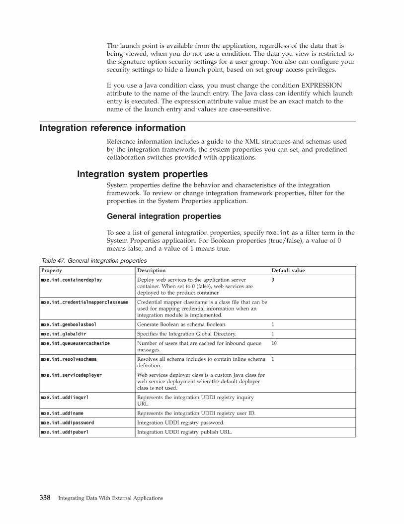
The launch point is available from the application, regardless of the data that isbeing viewed, when you do not use a condition. The data you view is restricted tothe signature option security settings for a user group. You also can configure yoursecurity settings to hide a launch point, based on set group access privileges.
If you use a Java condition class, you must change the condition EXPRESSIONattribute to the name of the launch entry. The Java class can identify which launchentry is executed. The expression attribute value must be an exact match to thename of the launch entry and values are case-sensitive.
Integration reference informationReference information includes a guide to the XML structures and schemas usedby the integration framework, the system properties you can set, and predefinedcollaboration switches provided with applications.
Integration system propertiesSystem properties define the behavior and characteristics of the integrationframework. To review or change integration framework properties, filter for theproperties in the System Properties application.
General integration properties
To see a list of general integration properties, specify mxe.int as a filter term in theSystem Properties application. For Boolean properties (true/false), a value of 0means false, and a value of 1 means true.
Table 47. General integration properties
Property Description Default value
mxe.int.containerdeploy Deploy web services to the application servercontainer. When set to 0 (false), web services aredeployed to the product container.
0
mxe.int.credentialmapperclassname Credential mapper classname is a class file that can beused for mapping credential information when anintegration module is implemented.
mxe.int.genboolasbool Generate Boolean as schema Boolean. 1
mxe.int.globaldir Specifies the Integration Global Directory. 1
mxe.int.queueusercachesize Number of users that are cached for inbound queuemessages.
10
mxe.int.resolveschema Resolves all schema includes to contain inline schemadefinition.
1
mxe.int.servicedeployer Web services deployer class is a custom Java class forweb service deployment when the default deployerclass is not used.
mxe.int.uddiinqurl Represents the integration UDDI registry inquiryURL.
mxe.int.uddiname Represents the integration UDDI registry user ID.
mxe.int.uddipassword Integration UDDI registry password.
mxe.int.uddipuburl Integration UDDI registry publish URL.
338 Integrating Data With External Applications
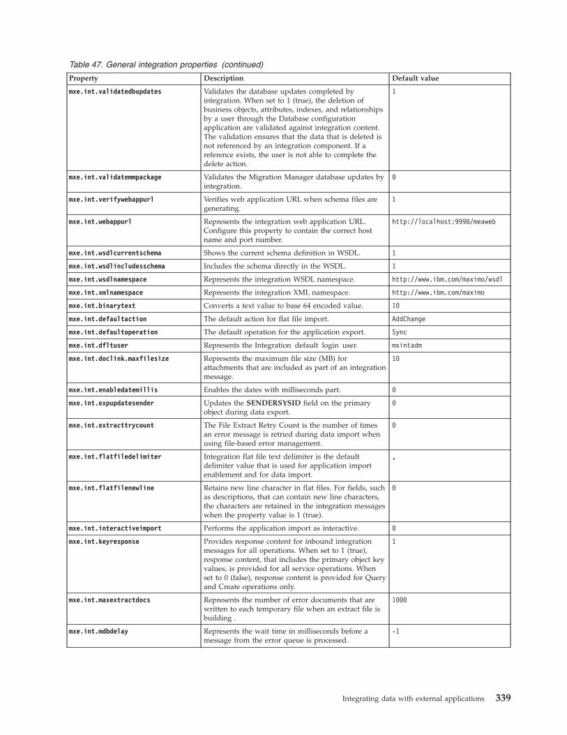
Table 47. General integration properties (continued)
Property Description Default value
mxe.int.validatedbupdates Validates the database updates completed byintegration. When set to 1 (true), the deletion ofbusiness objects, attributes, indexes, and relationshipsby a user through the Database configurationapplication are validated against integration content.The validation ensures that the data that is deleted isnot referenced by an integration component. If areference exists, the user is not able to complete thedelete action.
1
mxe.int.validatemmpackage Validates the Migration Manager database updates byintegration.
0
mxe.int.verifywebappurl Verifies web application URL when schema files aregenerating.
1
mxe.int.webappurl Represents the integration web application URL.Configure this property to contain the correct hostname and port number.
http://localhost:9998/meaweb
mxe.int.wsdlcurrentschema Shows the current schema definition in WSDL. 1
mxe.int.wsdlincludesschema Includes the schema directly in the WSDL. 1
mxe.int.wsdlnamespace Represents the integration WSDL namespace. http://www.ibm.com/maximo/wsdl
mxe.int.xmlnamespace Represents the integration XML namespace. http://www.ibm.com/maximo
mxe.int.binarytext Converts a text value to base 64 encoded value. 10
mxe.int.defaultaction The default action for flat file import. AddChange
mxe.int.defaultoperation The default operation for the application export. Sync
mxe.int.dfltuser Represents the Integration default login user. mxintadm
mxe.int.doclink.maxfilesize Represents the maximum file size (MB) forattachments that are included as part of an integrationmessage.
10
mxe.int.enabledatemillis Enables the dates with milliseconds part. 0
mxe.int.expupdatesender Updates the SENDERSYSID field on the primaryobject during data export.
0
mxe.int.extracttrycount The File Extract Retry Count is the number of timesan error message is retried during data import whenusing file-based error management.
0
mxe.int.flatfiledelimiter Integration flat file text delimiter is the defaultdelimiter value that is used for application importenablement and for data import.
,
mxe.int.flatfilenewline Retains new line character in flat files. For fields, suchas descriptions, that can contain new line characters,the characters are retained in the integration messageswhen the property value is 1 (true).
0
mxe.int.interactiveimport Performs the application import as interactive. 0
mxe.int.keyresponse Provides response content for inbound integrationmessages for all operations. When set to 1 (true),response content, that includes the primary object keyvalues, is provided for all service operations. Whenset to 0 (false), response content is provided for Queryand Create operations only.
1
mxe.int.maxextractdocs Represents the number of error documents that arewritten to each temporary file when an extract file isbuilding .
1000
mxe.int.mdbdelay Represents the wait time in milliseconds before amessage from the error queue is processed.
-1
Integrating data with external applications 339
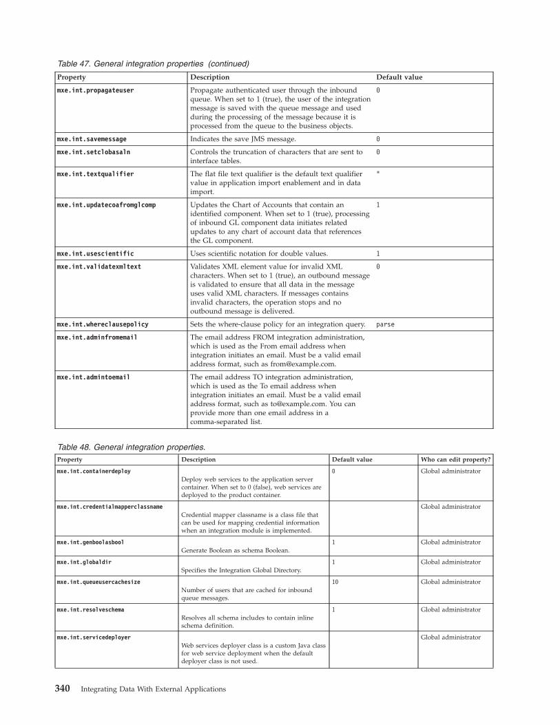
Table 47. General integration properties (continued)
Property Description Default value
mxe.int.propagateuser Propagate authenticated user through the inboundqueue. When set to 1 (true), the user of the integrationmessage is saved with the queue message and usedduring the processing of the message because it isprocessed from the queue to the business objects.
0
mxe.int.savemessage Indicates the save JMS message. 0
mxe.int.setclobasaln Controls the truncation of characters that are sent tointerface tables.
0
mxe.int.textqualifier The flat file text qualifier is the default text qualifiervalue in application import enablement and in dataimport.
"
mxe.int.updatecoafromglcomp Updates the Chart of Accounts that contain anidentified component. When set to 1 (true), processingof inbound GL component data initiates relatedupdates to any chart of account data that referencesthe GL component.
1
mxe.int.usescientific Uses scientific notation for double values. 1
mxe.int.validatexmltext Validates XML element value for invalid XMLcharacters. When set to 1 (true), an outbound messageis validated to ensure that all data in the messageuses valid XML characters. If messages containsinvalid characters, the operation stops and nooutbound message is delivered.
0
mxe.int.whereclausepolicy Sets the where-clause policy for an integration query. parse
mxe.int.adminfromemail The email address FROM integration administration,which is used as the From email address whenintegration initiates an email. Must be a valid emailaddress format, such as [email protected].
mxe.int.admintoemail The email address TO integration administration,which is used as the To email address whenintegration initiates an email. Must be a valid emailaddress format, such as [email protected]. You canprovide more than one email address in acomma-separated list.
Table 48. General integration properties.Property Description Default value Who can edit property?
mxe.int.containerdeployDeploy web services to the application servercontainer. When set to 0 (false), web services aredeployed to the product container.
0 Global administrator
mxe.int.credentialmapperclassnameCredential mapper classname is a class file thatcan be used for mapping credential informationwhen an integration module is implemented.
Global administrator
mxe.int.genboolasboolGenerate Boolean as schema Boolean.
1 Global administrator
mxe.int.globaldirSpecifies the Integration Global Directory.
1 Global administrator
mxe.int.queueusercachesizeNumber of users that are cached for inboundqueue messages.
10 Global administrator
mxe.int.resolveschemaResolves all schema includes to contain inlineschema definition.
1 Global administrator
mxe.int.servicedeployerWeb services deployer class is a custom Java classfor web service deployment when the defaultdeployer class is not used.
Global administrator
340 Integrating Data With External Applications
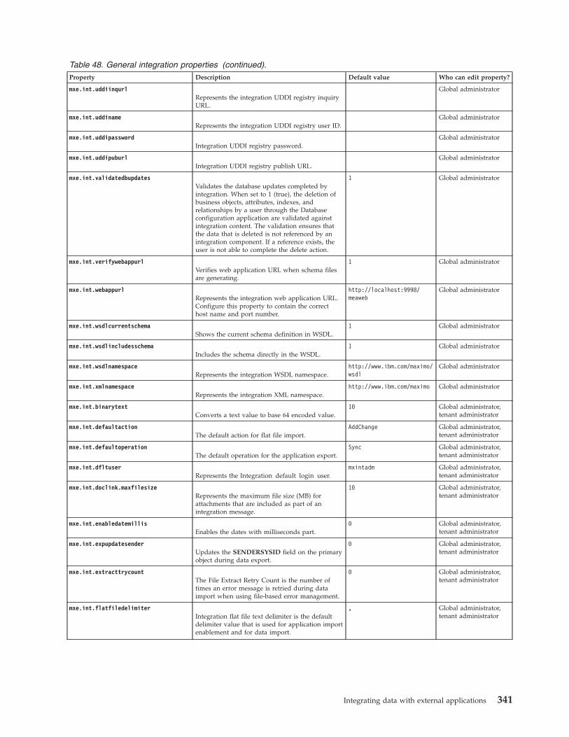
Table 48. General integration properties (continued).Property Description Default value Who can edit property?
mxe.int.uddiinqurlRepresents the integration UDDI registry inquiryURL.
Global administrator
mxe.int.uddinameRepresents the integration UDDI registry user ID.
Global administrator
mxe.int.uddipasswordIntegration UDDI registry password.
Global administrator
mxe.int.uddipuburlIntegration UDDI registry publish URL.
Global administrator
mxe.int.validatedbupdatesValidates the database updates completed byintegration. When set to 1 (true), the deletion ofbusiness objects, attributes, indexes, andrelationships by a user through the Databaseconfiguration application are validated againstintegration content. The validation ensures thatthe data that is deleted is not referenced by anintegration component. If a reference exists, theuser is not able to complete the delete action.
1 Global administrator
mxe.int.verifywebappurlVerifies web application URL when schema filesare generating.
1 Global administrator
mxe.int.webappurlRepresents the integration web application URL.Configure this property to contain the correcthost name and port number.
http://localhost:9998/meaweb
Global administrator
mxe.int.wsdlcurrentschemaShows the current schema definition in WSDL.
1 Global administrator
mxe.int.wsdlincludesschemaIncludes the schema directly in the WSDL.
1 Global administrator
mxe.int.wsdlnamespaceRepresents the integration WSDL namespace.
http://www.ibm.com/maximo/wsdl
Global administrator
mxe.int.xmlnamespaceRepresents the integration XML namespace.
http://www.ibm.com/maximo Global administrator
mxe.int.binarytextConverts a text value to base 64 encoded value.
10 Global administrator,tenant administrator
mxe.int.defaultactionThe default action for flat file import.
AddChange Global administrator,tenant administrator
mxe.int.defaultoperationThe default operation for the application export.
Sync Global administrator,tenant administrator
mxe.int.dfltuserRepresents the Integration default login user.
mxintadm Global administrator,tenant administrator
mxe.int.doclink.maxfilesizeRepresents the maximum file size (MB) forattachments that are included as part of anintegration message.
10 Global administrator,tenant administrator
mxe.int.enabledatemillisEnables the dates with milliseconds part.
0 Global administrator,tenant administrator
mxe.int.expupdatesenderUpdates the SENDERSYSID field on the primaryobject during data export.
0 Global administrator,tenant administrator
mxe.int.extracttrycountThe File Extract Retry Count is the number oftimes an error message is retried during dataimport when using file-based error management.
0 Global administrator,tenant administrator
mxe.int.flatfiledelimiterIntegration flat file text delimiter is the defaultdelimiter value that is used for application importenablement and for data import.
, Global administrator,tenant administrator
Integrating data with external applications 341
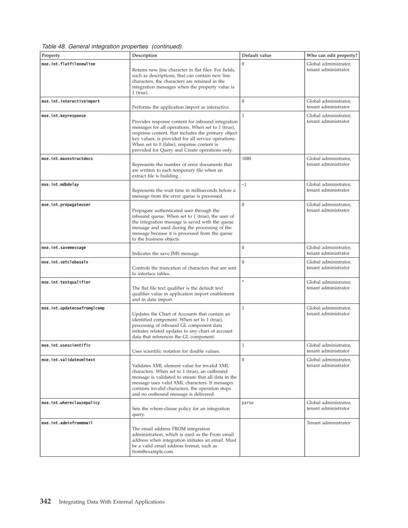
Table 48. General integration properties (continued).Property Description Default value Who can edit property?
mxe.int.flatfilenewlineRetains new line character in flat files. For fields,such as descriptions, that can contain new linecharacters, the characters are retained in theintegration messages when the property value is1 (true).
0 Global administrator,tenant administrator
mxe.int.interactiveimportPerforms the application import as interactive.
0 Global administrator,tenant administrator
mxe.int.keyresponseProvides response content for inbound integrationmessages for all operations. When set to 1 (true),response content, that includes the primary objectkey values, is provided for all service operations.When set to 0 (false), response content isprovided for Query and Create operations only.
1 Global administrator,tenant administrator
mxe.int.maxextractdocsRepresents the number of error documents thatare written to each temporary file when anextract file is building .
1000 Global administrator,tenant administrator
mxe.int.mdbdelayRepresents the wait time in milliseconds before amessage from the error queue is processed.
-1 Global administrator,tenant administrator
mxe.int.propagateuserPropagate authenticated user through theinbound queue. When set to 1 (true), the user ofthe integration message is saved with the queuemessage and used during the processing of themessage because it is processed from the queueto the business objects.
0 Global administrator,tenant administrator
mxe.int.savemessageIndicates the save JMS message.
0 Global administrator,tenant administrator
mxe.int.setclobasalnControls the truncation of characters that are sentto interface tables.
0 Global administrator,tenant administrator
mxe.int.textqualifierThe flat file text qualifier is the default textqualifier value in application import enablementand in data import.
" Global administrator,tenant administrator
mxe.int.updatecoafromglcompUpdates the Chart of Accounts that contain anidentified component. When set to 1 (true),processing of inbound GL component datainitiates related updates to any chart of accountdata that references the GL component.
1 Global administrator,tenant administrator
mxe.int.usescientificUses scientific notation for double values.
1 Global administrator,tenant administrator
mxe.int.validatexmltextValidates XML element value for invalid XMLcharacters. When set to 1 (true), an outboundmessage is validated to ensure that all data in themessage uses valid XML characters. If messagescontains invalid characters, the operation stopsand no outbound message is delivered.
0 Global administrator,tenant administrator
mxe.int.whereclausepolicySets the where-clause policy for an integrationquery.
parse Global administrator,tenant administrator
mxe.int.adminfromemailThe email address FROM integrationadministration, which is used as the From emailaddress when integration initiates an email. Mustbe a valid email address format, such [email protected].
Tenant administrator
342 Integrating Data With External Applications
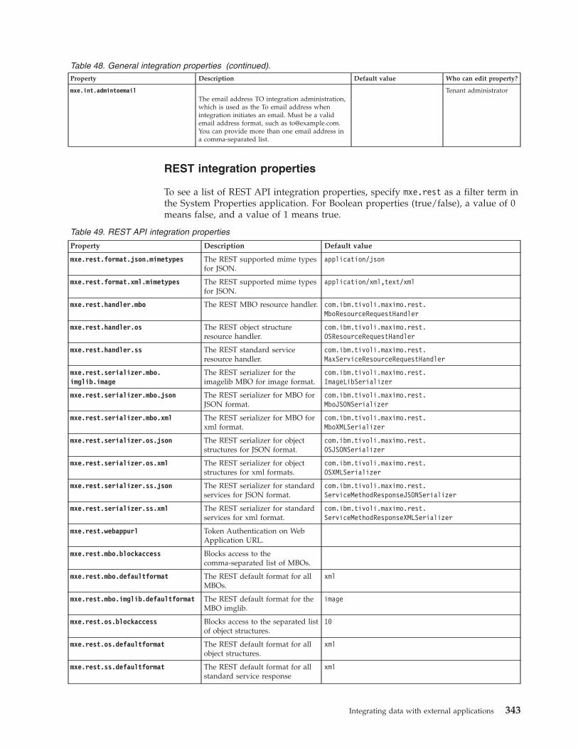
Table 48. General integration properties (continued).Property Description Default value Who can edit property?
mxe.int.admintoemailThe email address TO integration administration,which is used as the To email address whenintegration initiates an email. Must be a validemail address format, such as [email protected] can provide more than one email address ina comma-separated list.
Tenant administrator
REST integration properties
To see a list of REST API integration properties, specify mxe.rest as a filter term inthe System Properties application. For Boolean properties (true/false), a value of 0means false, and a value of 1 means true.
Table 49. REST API integration properties
Property Description Default value
mxe.rest.format.json.mimetypes The REST supported mime typesfor JSON.
application/json
mxe.rest.format.xml.mimetypes The REST supported mime typesfor JSON.
application/xml,text/xml
mxe.rest.handler.mbo The REST MBO resource handler. com.ibm.tivoli.maximo.rest.MboResourceRequestHandler
mxe.rest.handler.os The REST object structureresource handler.
com.ibm.tivoli.maximo.rest.OSResourceRequestHandler
mxe.rest.handler.ss The REST standard serviceresource handler.
com.ibm.tivoli.maximo.rest.MaxServiceResourceRequestHandler
mxe.rest.serializer.mbo.imglib.image
The REST serializer for theimagelib MBO for image format.
com.ibm.tivoli.maximo.rest.ImageLibSerializer
mxe.rest.serializer.mbo.json The REST serializer for MBO forJSON format.
com.ibm.tivoli.maximo.rest.MboJSONSerializer
mxe.rest.serializer.mbo.xml The REST serializer for MBO forxml format.
com.ibm.tivoli.maximo.rest.MboXMLSerializer
mxe.rest.serializer.os.json The REST serializer for objectstructures for JSON format.
com.ibm.tivoli.maximo.rest.OSJSONSerializer
mxe.rest.serializer.os.xml The REST serializer for objectstructures for xml formats.
com.ibm.tivoli.maximo.rest.OSXMLSerializer
mxe.rest.serializer.ss.json The REST serializer for standardservices for JSON format.
com.ibm.tivoli.maximo.rest.ServiceMethodResponseJSONSerializer
mxe.rest.serializer.ss.xml The REST serializer for standardservices for xml format.
com.ibm.tivoli.maximo.rest.ServiceMethodResponseXMLSerializer
mxe.rest.webappurl Token Authentication on WebApplication URL.
mxe.rest.mbo.blockaccess Blocks access to thecomma-separated list of MBOs.
mxe.rest.mbo.defaultformat The REST default format for allMBOs.
xml
mxe.rest.mbo.imglib.defaultformat The REST default format for theMBO imglib.
image
mxe.rest.os.blockaccess Blocks access to the separated listof object structures.
10
mxe.rest.os.defaultformat The REST default format for allobject structures.
xml
mxe.rest.ss.defaultformat The REST default format for allstandard service response
xml
Integrating data with external applications 343
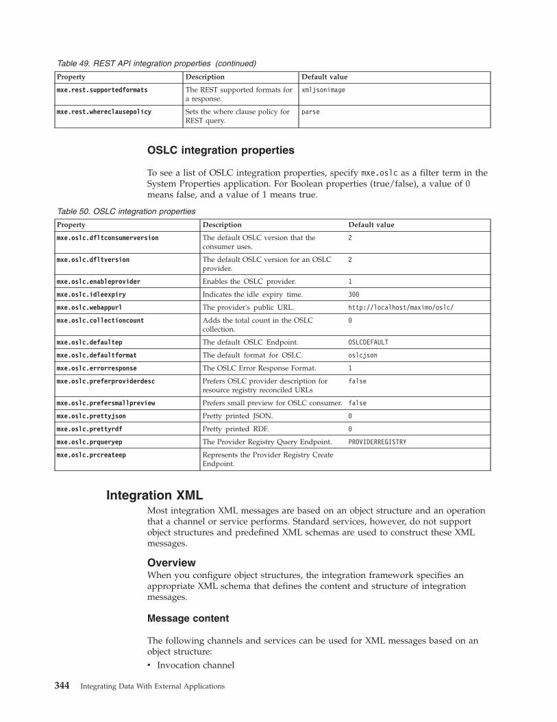
Table 49. REST API integration properties (continued)
Property Description Default value
mxe.rest.supportedformats The REST supported formats fora response.
xmljsonimage
mxe.rest.whereclausepolicy Sets the where clause policy forREST query.
parse
OSLC integration properties
To see a list of OSLC integration properties, specify mxe.oslc as a filter term in theSystem Properties application. For Boolean properties (true/false), a value of 0means false, and a value of 1 means true.
Table 50. OSLC integration properties
Property Description Default value
mxe.oslc.dfltconsumerversion The default OSLC version that theconsumer uses.
2
mxe.oslc.dfltversion The default OSLC version for an OSLCprovider.
2
mxe.oslc.enableprovider Enables the OSLC provider. 1
mxe.oslc.idleexpiry Indicates the idle expiry time. 300
mxe.oslc.webappurl The provider's public URL. http://localhost/maximo/oslc/
mxe.oslc.collectioncount Adds the total count in the OSLCcollection.
0
mxe.oslc.defaultep The default OSLC Endpoint. OSLCDEFAULT
mxe.oslc.defaultformat The default format for OSLC. oslcjson
mxe.oslc.errorresponse The OSLC Error Response Format. 1
mxe.oslc.preferproviderdesc Prefers OSLC provider description forresource registry reconciled URLs
false
mxe.oslc.prefersmallpreview Prefers small preview for OSLC consumer. false
mxe.oslc.prettyjson Pretty printed JSON. 0
mxe.oslc.prettyrdf Pretty printed RDF. 0
mxe.oslc.prqueryep The Provider Registry Query Endpoint. PROVIDERREGISTRY
mxe.oslc.prcreateep Represents the Provider Registry CreateEndpoint.
Integration XMLMost integration XML messages are based on an object structure and an operationthat a channel or service performs. Standard services, however, do not supportobject structures and predefined XML schemas are used to construct these XMLmessages.
OverviewWhen you configure object structures, the integration framework specifies anappropriate XML schema that defines the content and structure of integrationmessages.
Message content
The following channels and services can be used for XML messages based on anobject structure:v Invocation channel
344 Integrating Data With External Applications
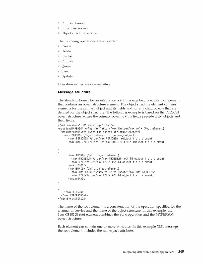
v Publish channelv Enterprise servicev Object structure service
The following operations are supported:v Createv Deletev Invokev Publishv Queryv Syncv Update
Operation values are case-sensitive.
Message structure
The standard format for an integration XML message begins with a root elementthat contains an object structure element. The object structure element containselements for the primary object and its fields and for any child objects that aredefined for the object structure. The following example is based on the PERSONobject structure, where the primary object and its fields precede child objects andtheir fields.<?xml version="1.0" encoding="UTF-8"?><max:SyncMXPERSON xmlns:max="http://www.ibm.com/maximo"> (Root element)
<max:MXPERSONSet> (Sets the object structure element)<max:PERSON> (Object element for primary object)
<max:PERSONID>Value</max:PERSONID> (Object field element)<max:EMPLOYEETYPE>Value</max:EMPLOYEETYPE> (Object field element)
.
.
.<max:PHONE> (Child object element)
<max:PHONENUM>Value</max:PHONENUM> (Child object field element)<max:TYPE>Value</max:TYPE> (Child object field element)
</max:PHONE><max:EMAIL> (Child object element)
<max:EMAILADDRESS>New value to update</max:EMAILADDRESS><max:TYPE>Value</max:TYPE> (Child object field element)
</max:EMAIL>...
</max:PERSON></max:MXPERSONSet>
</max:SyncMXPERSON>
The name of the root element is a concatenation of the operation specified for thechannel or service and the name of the object structure. In this example, theSyncMXPERSON root element combines the Sync operation and the MXPERSONobject structure.
Each element can contain one or more attributes. In this example XML message,the root element includes the namespace attribute.
Integrating data with external applications 345
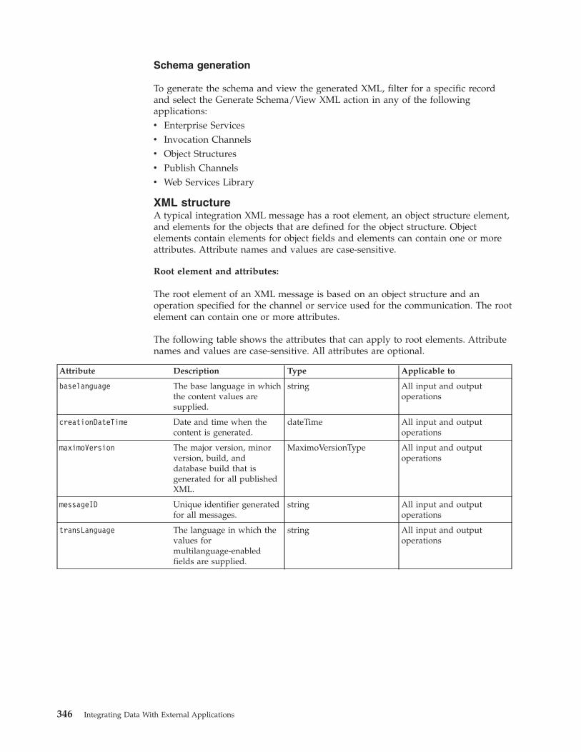
Schema generation
To generate the schema and view the generated XML, filter for a specific recordand select the Generate Schema/View XML action in any of the followingapplications:v Enterprise Servicesv Invocation Channelsv Object Structuresv Publish Channelsv Web Services Library
XML structureA typical integration XML message has a root element, an object structure element,and elements for the objects that are defined for the object structure. Objectelements contain elements for object fields and elements can contain one or moreattributes. Attribute names and values are case-sensitive.
Root element and attributes:
The root element of an XML message is based on an object structure and anoperation specified for the channel or service used for the communication. The rootelement can contain one or more attributes.
The following table shows the attributes that can apply to root elements. Attributenames and values are case-sensitive. All attributes are optional.
Attribute Description Type Applicable to
baselanguage The base language in whichthe content values aresupplied.
string All input and outputoperations
creationDateTime Date and time when thecontent is generated.
dateTime All input and outputoperations
maximoVersion The major version, minorversion, build, anddatabase build that isgenerated for all publishedXML.
MaximoVersionType All input and outputoperations
messageID Unique identifier generatedfor all messages.
string All input and outputoperations
transLanguage The language in which thevalues formultilanguage-enabledfields are supplied.
string All input and outputoperations
346 Integrating Data With External Applications
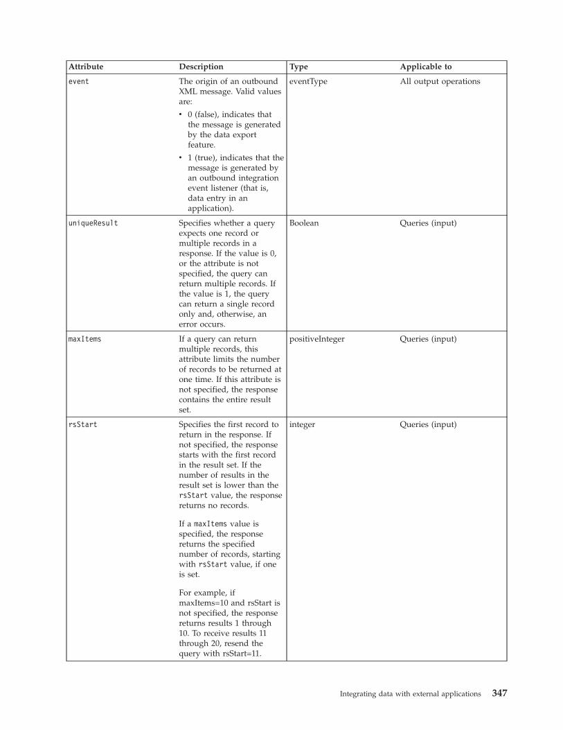
Attribute Description Type Applicable to
event The origin of an outboundXML message. Valid valuesare:
v 0 (false), indicates thatthe message is generatedby the data exportfeature.
v 1 (true), indicates that themessage is generated byan outbound integrationevent listener (that is,data entry in anapplication).
eventType All output operations
uniqueResult Specifies whether a queryexpects one record ormultiple records in aresponse. If the value is 0,or the attribute is notspecified, the query canreturn multiple records. Ifthe value is 1, the querycan return a single recordonly and, otherwise, anerror occurs.
Boolean Queries (input)
maxItems If a query can returnmultiple records, thisattribute limits the numberof records to be returned atone time. If this attribute isnot specified, the responsecontains the entire resultset.
positiveInteger Queries (input)
rsStart Specifies the first record toreturn in the response. Ifnot specified, the responsestarts with the first recordin the result set. If thenumber of results in theresult set is lower than thersStart value, the responsereturns no records.
If a maxItems value isspecified, the responsereturns the specifiednumber of records, startingwith rsStart value, if oneis set.
For example, ifmaxItems=10 and rsStart isnot specified, the responsereturns results 1 through10. To receive results 11through 20, resend thequery with rsStart=11.
integer Queries (input)
Integrating data with external applications 347
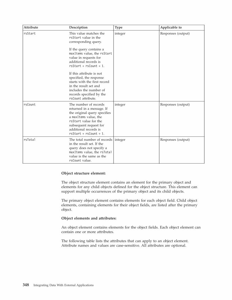
Attribute Description Type Applicable to
rsStart This value matches thersStart value in thecorresponding query.
If the query contains amaxItems value, the rsStartvalue in requests foradditional records isrsStart + rsCount + 1.
If this attribute is notspecified, the responsestarts with the first recordin the result set andincludes the number ofrecords specified by thersCount attribute.
integer Responses (output)
rsCount The number of recordsreturned in a message. Ifthe original query specifiesa maxItems value, thersStart value for thesubsequent request foradditional records isrsStart + rsCount + 1.
integer Responses (output)
rsTotal The total number of recordsin the result set. If thequery does not specify amaxItems value, the rsTotalvalue is the same as thersCount value.
integer Responses (output)
Object structure element:
The object structure element contains an element for the primary object andelements for any child objects defined for the object structure. This element cansupport multiple occurrences of the primary object and its child objects.
The primary object element contains elements for each object field. Child objectelements, containing elements for their object fields, are listed after the primaryobject.
Object elements and attributes:
An object element contains elements for the object fields. Each object element cancontain one or more attributes.
The following table lists the attributes that can apply to an object element.Attribute names and values are case-sensitive. All attributes are optional.
348 Integrating Data With External Applications
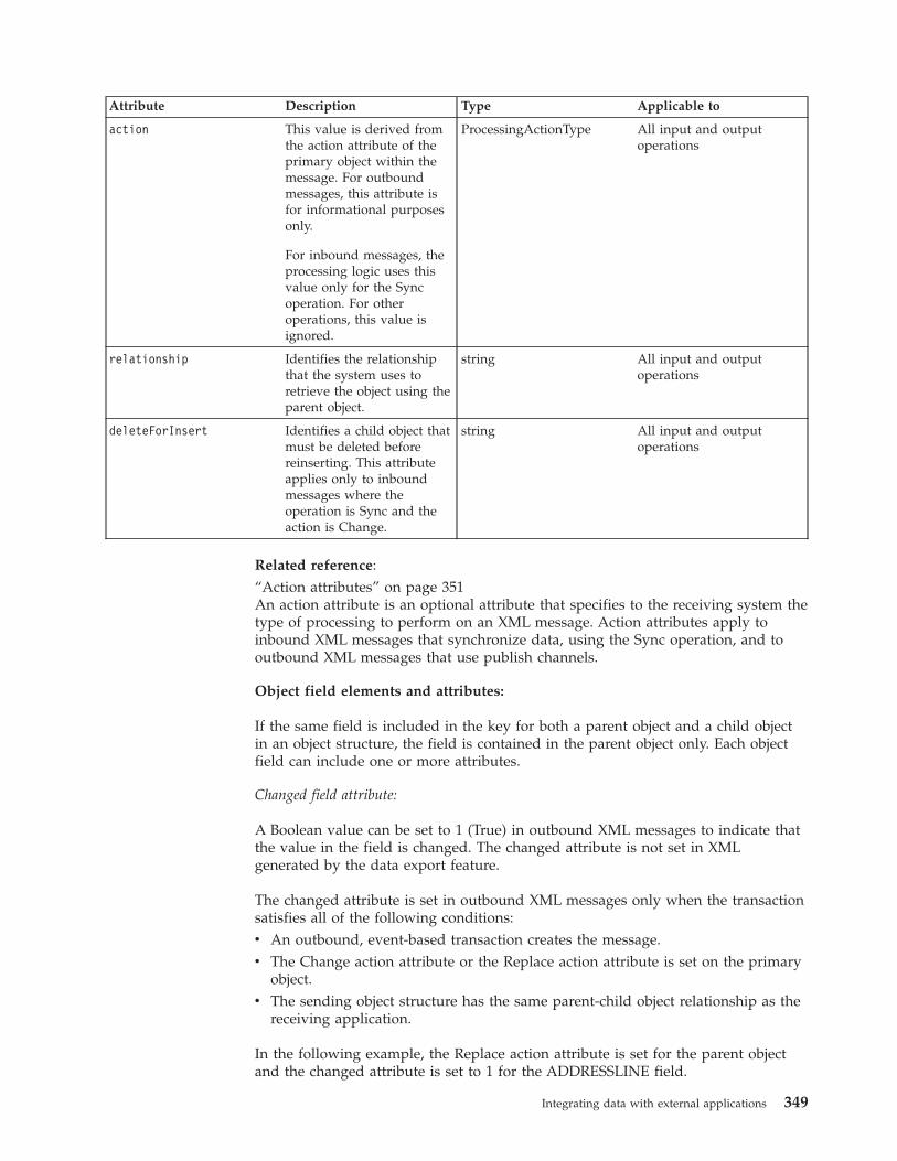
Attribute Description Type Applicable to
action This value is derived fromthe action attribute of theprimary object within themessage. For outboundmessages, this attribute isfor informational purposesonly.
For inbound messages, theprocessing logic uses thisvalue only for the Syncoperation. For otheroperations, this value isignored.
ProcessingActionType All input and outputoperations
relationship Identifies the relationshipthat the system uses toretrieve the object using theparent object.
string All input and outputoperations
deleteForInsert Identifies a child object thatmust be deleted beforereinserting. This attributeapplies only to inboundmessages where theoperation is Sync and theaction is Change.
string All input and outputoperations
Related reference:“Action attributes” on page 351An action attribute is an optional attribute that specifies to the receiving system thetype of processing to perform on an XML message. Action attributes apply toinbound XML messages that synchronize data, using the Sync operation, and tooutbound XML messages that use publish channels.
Object field elements and attributes:
If the same field is included in the key for both a parent object and a child objectin an object structure, the field is contained in the parent object only. Each objectfield can include one or more attributes.
Changed field attribute:
A Boolean value can be set to 1 (True) in outbound XML messages to indicate thatthe value in the field is changed. The changed attribute is not set in XMLgenerated by the data export feature.
The changed attribute is set in outbound XML messages only when the transactionsatisfies all of the following conditions:v An outbound, event-based transaction creates the message.v The Change action attribute or the Replace action attribute is set on the primary
object.v The sending object structure has the same parent-child object relationship as the
receiving application.
In the following example, the Replace action attribute is set for the parent objectand the changed attribute is set to 1 for the ADDRESSLINE field.
Integrating data with external applications 349
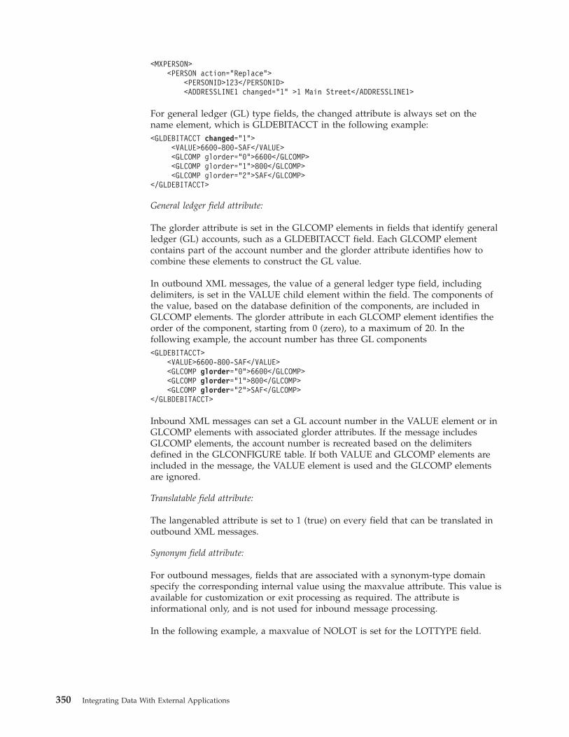
<MXPERSON><PERSON action="Replace">
<PERSONID>123</PERSONID><ADDRESSLINE1 changed="1" >1 Main Street</ADDRESSLINE1>
For general ledger (GL) type fields, the changed attribute is always set on thename element, which is GLDEBITACCT in the following example:<GLDEBITACCT changed="1">
<VALUE>6600-800-SAF</VALUE><GLCOMP glorder="0">6600</GLCOMP><GLCOMP glorder="1">800</GLCOMP><GLCOMP glorder="2">SAF</GLCOMP>
</GLDEBITACCT>
General ledger field attribute:
The glorder attribute is set in the GLCOMP elements in fields that identify generalledger (GL) accounts, such as a GLDEBITACCT field. Each GLCOMP elementcontains part of the account number and the glorder attribute identifies how tocombine these elements to construct the GL value.
In outbound XML messages, the value of a general ledger type field, includingdelimiters, is set in the VALUE child element within the field. The components ofthe value, based on the database definition of the components, are included inGLCOMP elements. The glorder attribute in each GLCOMP element identifies theorder of the component, starting from 0 (zero), to a maximum of 20. In thefollowing example, the account number has three GL components<GLDEBITACCT>
<VALUE>6600-800-SAF</VALUE><GLCOMP glorder="0">6600</GLCOMP><GLCOMP glorder="1">800</GLCOMP><GLCOMP glorder="2">SAF</GLCOMP>
</GLBDEBITACCT>
Inbound XML messages can set a GL account number in the VALUE element or inGLCOMP elements with associated glorder attributes. If the message includesGLCOMP elements, the account number is recreated based on the delimitersdefined in the GLCONFIGURE table. If both VALUE and GLCOMP elements areincluded in the message, the VALUE element is used and the GLCOMP elementsare ignored.
Translatable field attribute:
The langenabled attribute is set to 1 (true) on every field that can be translated inoutbound XML messages.
Synonym field attribute:
For outbound messages, fields that are associated with a synonym-type domainspecify the corresponding internal value using the maxvalue attribute. This value isavailable for customization or exit processing as required. The attribute isinformational only, and is not used for inbound message processing.
In the following example, a maxvalue of NOLOT is set for the LOTTYPE field.
350 Integrating Data With External Applications
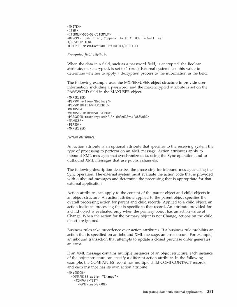
<MXITEM><ITEM><ITEMNUM>560-00</ITEMNUM><DESCRIPTION>Tubing, Copper-1 In ID X .030 In Wall Test</DESCRIPTION><LOTTYPE maxvalue="NOLOT">NOLOT</LOTTYPE>
Encrypted field attribute:
When the data in a field, such as a password field, is encrypted, the Booleanattribute, maxencrypted, is set to 1 (true). External systems use this value todetermine whether to apply a decryption process to the information in the field.
The following example uses the MXPERSUSER object structure to provide userinformation, including a password, and the maxencrypted attribute is set on thePASSWORD field in the MAXUSER object.<MXPERUSER><PERSON action="Replace"><PERSONID>123</PERSONID><MAXUSER><MAXUSERID>10</MAXUSERID><PASSWORD maxencrypted=”1”> dmFzdG8=</PASSWORD><MAXUSER><PERSON><MXPERUSER>
Action attributes:
An action attribute is an optional attribute that specifies to the receiving system thetype of processing to perform on an XML message. Action attributes apply toinbound XML messages that synchronize data, using the Sync operation, and tooutbound XML messages that use publish channels.
The following description describes the processing for inbound messages using theSync operation. The external system must evaluate the action code that is providedwith outbound messages and determine the processing that is appropriate for thatexternal application.
Action attributes can apply to the content of the parent object and child objects inan object structure. An action attribute applied to the parent object specifies theoverall processing action for parent and child records. Applied to a child object, anaction indicates processing that is specific to that record. An attribute provided fora child object is evaluated only when the primary object has an action value ofChange. When the action for the primary object is not Change, actions on the childobject are ignored.
Business rules take precedence over action attributes. If a business rule prohibits anaction that is specified on an inbound XML message, an error occurs. For example,an inbound transaction that attempts to update a closed purchase order generatesan error.
If an XML message contains multiple instances of an object structure, each instanceof the object structure can specify a different action attribute. In the followingexample, the COMPANIES record has multiple child COMPCONTACT records,and each instance has its own action attribute.<MXVENDOR>
<COMPANIES action="Change"><COMPANY>TEST4
<NAME>test</NAME>
Integrating data with external applications 351
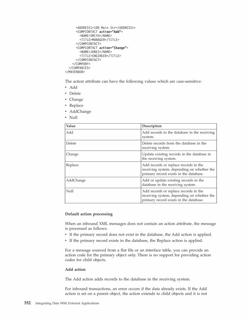
<ADDRESS1>100 Main Str</ADDRESS1><COMPCONTACT action="Add">
<NAME>SMITH</NAME><TITLE>MANAGER</TITLE>
</COMPCONTACT><COMPCONTACT action="Change">
<NAME>JONES</NAME><TITLE>ENGINEER</TITLE>
</COMPCONTACT></COMPANY>
</COMPANIES></MXVENDOR>
The action attribute can have the following values which are case-sensitive:v Addv Deletev Changev Replacev AddChangev Null
Value Description
Add Add records to the database in the receivingsystem.
Delete Delete records from the database in thereceiving system.
Change Update existing records in the database inthe receiving system.
Replace Add records or replace records in thereceiving system, depending on whether theprimary record exists in the database.
AddChange Add or update existing records in thedatabase in the receiving system.
Null Add records or replace records in thereceiving system, depending on whether theprimary record exists in the database.
Default action processing
When an inbound XML messages does not contain an action attribute, the messageis processed as follows:v If the primary record does not exist in the database, the Add action is applied.v If the primary record exists in the database, the Replace action is applied.
For a message sourced from a flat file or an interface table, you can provide anaction code for the primary object only. There is no support for providing actioncodes for child objects.
Add action
The Add action adds records to the database in the receiving system.
For inbound transactions, an error occurs if the data already exists. If the Addaction is set on a parent object, the action extends to child objects and it is not
352 Integrating Data With External Applications
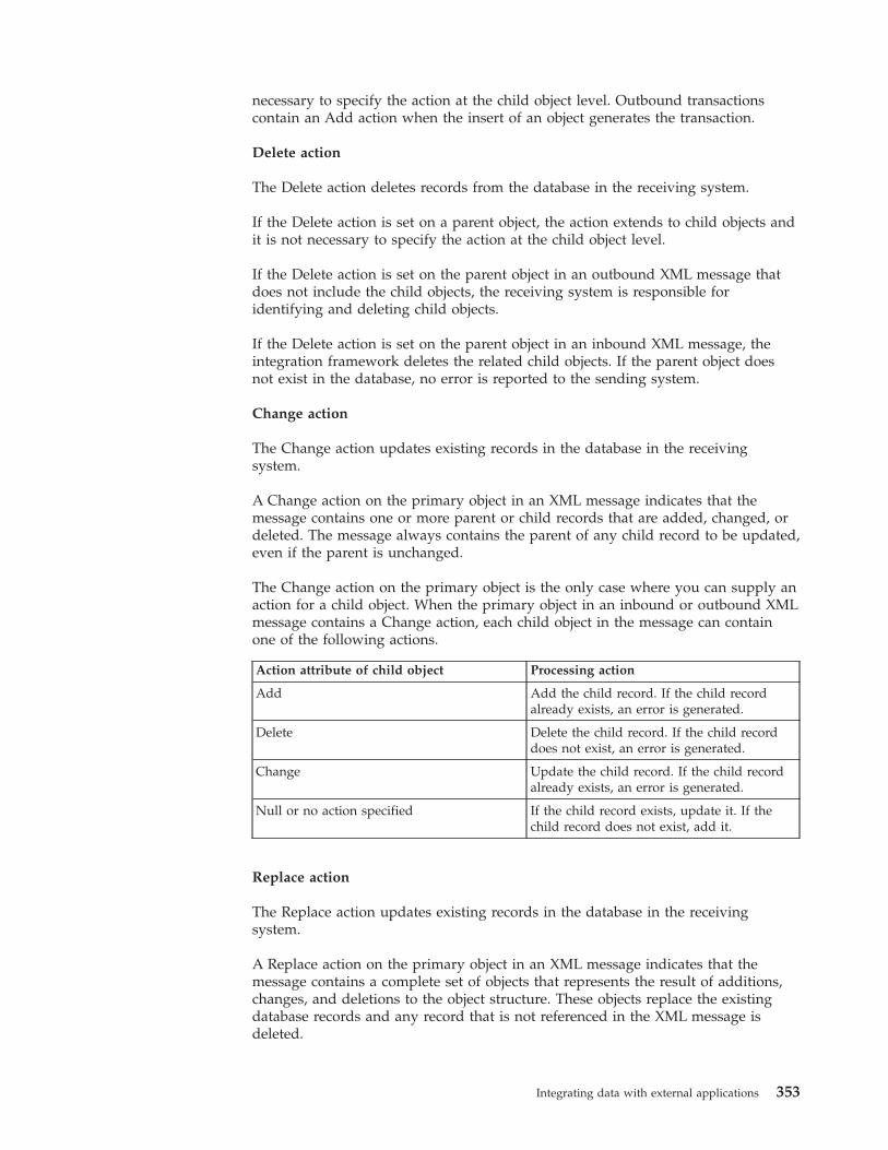
necessary to specify the action at the child object level. Outbound transactionscontain an Add action when the insert of an object generates the transaction.
Delete action
The Delete action deletes records from the database in the receiving system.
If the Delete action is set on a parent object, the action extends to child objects andit is not necessary to specify the action at the child object level.
If the Delete action is set on the parent object in an outbound XML message thatdoes not include the child objects, the receiving system is responsible foridentifying and deleting child objects.
If the Delete action is set on the parent object in an inbound XML message, theintegration framework deletes the related child objects. If the parent object doesnot exist in the database, no error is reported to the sending system.
Change action
The Change action updates existing records in the database in the receivingsystem.
A Change action on the primary object in an XML message indicates that themessage contains one or more parent or child records that are added, changed, ordeleted. The message always contains the parent of any child record to be updated,even if the parent is unchanged.
The Change action on the primary object is the only case where you can supply anaction for a child object. When the primary object in an inbound or outbound XMLmessage contains a Change action, each child object in the message can containone of the following actions.
Action attribute of child object Processing action
Add Add the child record. If the child recordalready exists, an error is generated.
Delete Delete the child record. If the child recorddoes not exist, an error is generated.
Change Update the child record. If the child recordalready exists, an error is generated.
Null or no action specified If the child record exists, update it. If thechild record does not exist, add it.
Replace action
The Replace action updates existing records in the database in the receivingsystem.
A Replace action on the primary object in an XML message indicates that themessage contains a complete set of objects that represents the result of additions,changes, and deletions to the object structure. These objects replace the existingdatabase records and any record that is not referenced in the XML message isdeleted.
Integrating data with external applications 353
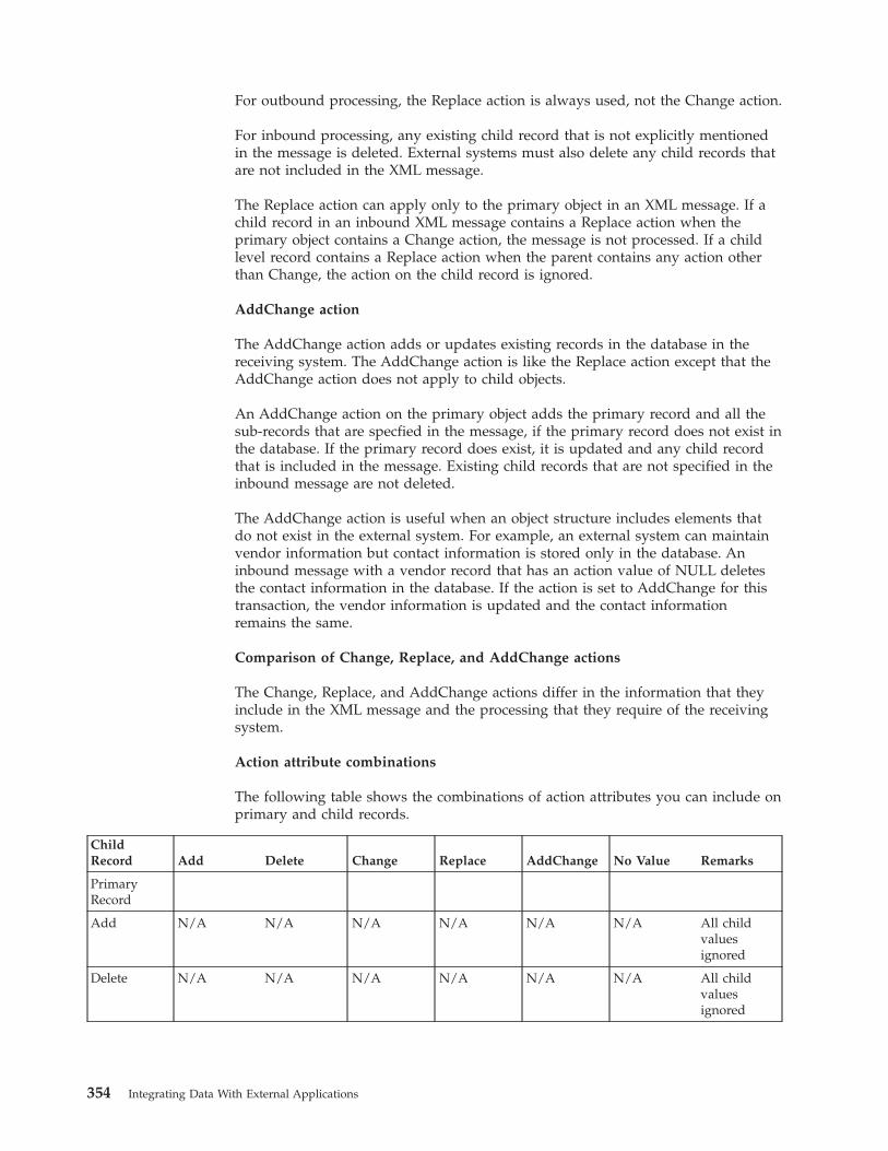
For outbound processing, the Replace action is always used, not the Change action.
For inbound processing, any existing child record that is not explicitly mentionedin the message is deleted. External systems must also delete any child records thatare not included in the XML message.
The Replace action can apply only to the primary object in an XML message. If achild record in an inbound XML message contains a Replace action when theprimary object contains a Change action, the message is not processed. If a childlevel record contains a Replace action when the parent contains any action otherthan Change, the action on the child record is ignored.
AddChange action
The AddChange action adds or updates existing records in the database in thereceiving system. The AddChange action is like the Replace action except that theAddChange action does not apply to child objects.
An AddChange action on the primary object adds the primary record and all thesub-records that are specfied in the message, if the primary record does not exist inthe database. If the primary record does exist, it is updated and any child recordthat is included in the message. Existing child records that are not specified in theinbound message are not deleted.
The AddChange action is useful when an object structure includes elements thatdo not exist in the external system. For example, an external system can maintainvendor information but contact information is stored only in the database. Aninbound message with a vendor record that has an action value of NULL deletesthe contact information in the database. If the action is set to AddChange for thistransaction, the vendor information is updated and the contact informationremains the same.
Comparison of Change, Replace, and AddChange actions
The Change, Replace, and AddChange actions differ in the information that theyinclude in the XML message and the processing that they require of the receivingsystem.
Action attribute combinations
The following table shows the combinations of action attributes you can include onprimary and child records.
ChildRecord Add Delete Change Replace AddChange No Value Remarks
PrimaryRecord
Add N/A N/A N/A N/A N/A N/A All childvaluesignored
Delete N/A N/A N/A N/A N/A N/A All childvaluesignored
354 Integrating Data With External Applications
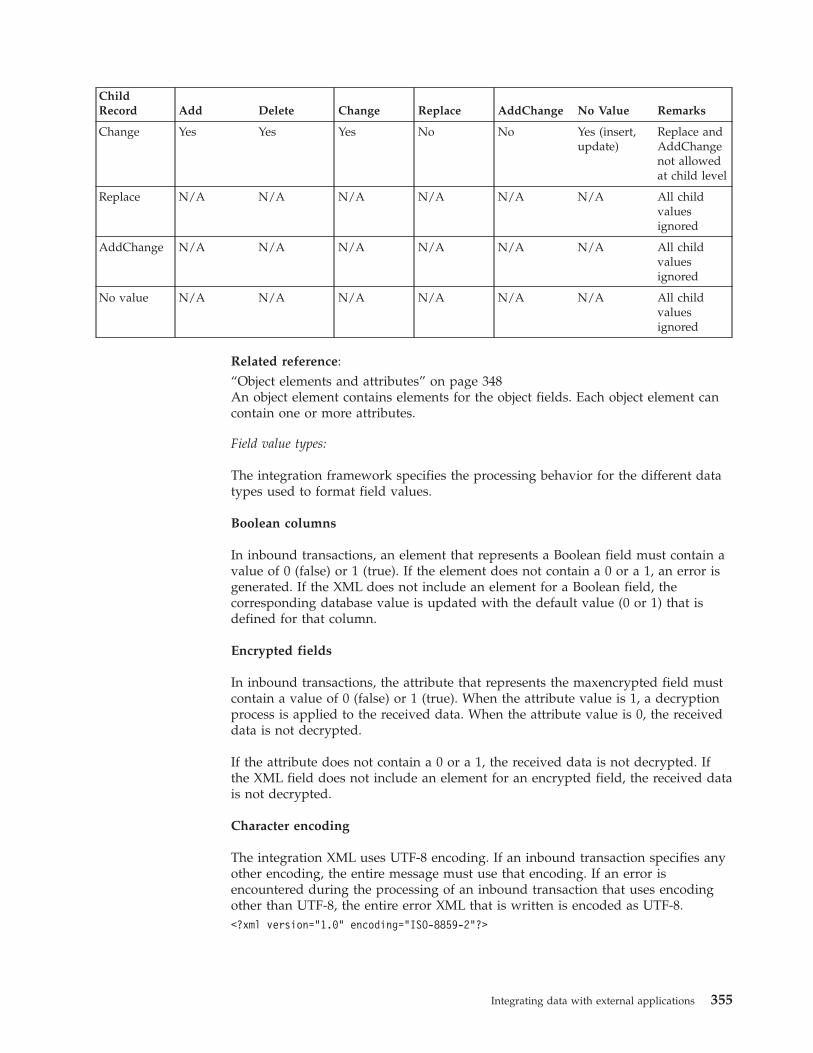
ChildRecord Add Delete Change Replace AddChange No Value Remarks
Change Yes Yes Yes No No Yes (insert,update)
Replace andAddChangenot allowedat child level
Replace N/A N/A N/A N/A N/A N/A All childvaluesignored
AddChange N/A N/A N/A N/A N/A N/A All childvaluesignored
No value N/A N/A N/A N/A N/A N/A All childvaluesignored
Related reference:“Object elements and attributes” on page 348An object element contains elements for the object fields. Each object element cancontain one or more attributes.
Field value types:
The integration framework specifies the processing behavior for the different datatypes used to format field values.
Boolean columns
In inbound transactions, an element that represents a Boolean field must contain avalue of 0 (false) or 1 (true). If the element does not contain a 0 or a 1, an error isgenerated. If the XML does not include an element for a Boolean field, thecorresponding database value is updated with the default value (0 or 1) that isdefined for that column.
Encrypted fields
In inbound transactions, the attribute that represents the maxencrypted field mustcontain a value of 0 (false) or 1 (true). When the attribute value is 1, a decryptionprocess is applied to the received data. When the attribute value is 0, the receiveddata is not decrypted.
If the attribute does not contain a 0 or a 1, the received data is not decrypted. Ifthe XML field does not include an element for an encrypted field, the received datais not decrypted.
Character encoding
The integration XML uses UTF-8 encoding. If an inbound transaction specifies anyother encoding, the entire message must use that encoding. If an error isencountered during the processing of an inbound transaction that uses encodingother than UTF-8, the entire error XML that is written is encoded as UTF-8.<?xml version="1.0" encoding="ISO-8859-2"?>
Integrating data with external applications 355
Date format
The integration XML supports the following ISO 8601 date format:2011-04-06T10:11:58-05:00
Null columns
If an element in an inbound transaction contains no value, the correspondingdatabase column is updated with a null value. If the XML does not include anelement for a particular field, that field is not updated in the database.
For inbound data that is sourced from a flat file or an interface table, you can set afield to null by providing ~NULL~ for the field value in the flat file or interfacetable. Integration processing creates an empty tag in the corresponding XMLmessage for any ~NULL~ values that are provided. This feature does not supportnumeric or date fields from an interface table source.
Number format
Regardless of the locale setting of the application server or the database, alldecimal fields must use a period (.) as the decimal placeholder. Do not formatnumbers to the left of the placeholder. This format applies to inbound andoutbound data.
$1,738,593.64 must be in the following format: 1738593.64
Integration XML schemasXML schemas for channels and services, excluding standard services, are based onthe configuration of the objects that are included in the object structure. You cangenerate schemas in the integration applications.
XML schemas overview:
An integration framework schema includes a predefined schema component formetadata as well as schema components based on configured objects, objectstructures, and standard services
Schemas can be generated to support XML-based integration scenarios where thefollowing components are used:v Object structure servicev Publish channelv Invocation channelv Enterprise servicev Standard service
Key fields
XML schema annotation identifies the key fields for a service or channel from theobject structure definition and the data dictionary definitions for the correspondingobject.
In the following example, the ITEMNUM element is identified as a key field in theschema for the MXITEM object structure.
356 Integrating Data With External Applications
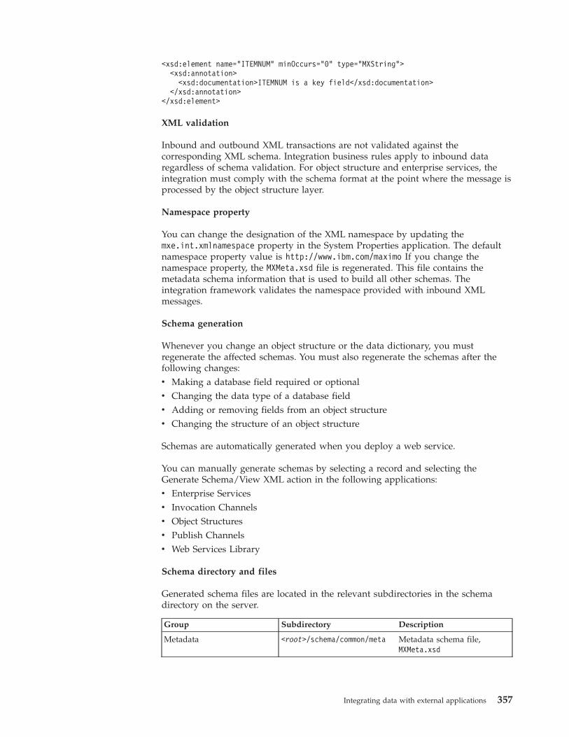
<xsd:element name="ITEMNUM" minOccurs="0" type="MXString"><xsd:annotation>
<xsd:documentation>ITEMNUM is a key field</xsd:documentation></xsd:annotation>
</xsd:element>
XML validation
Inbound and outbound XML transactions are not validated against thecorresponding XML schema. Integration business rules apply to inbound dataregardless of schema validation. For object structure and enterprise services, theintegration must comply with the schema format at the point where the message isprocessed by the object structure layer.
Namespace property
You can change the designation of the XML namespace by updating themxe.int.xmlnamespace property in the System Properties application. The defaultnamespace property value is http://www.ibm.com/maximo If you change thenamespace property, the MXMeta.xsd file is regenerated. This file contains themetadata schema information that is used to build all other schemas. Theintegration framework validates the namespace provided with inbound XMLmessages.
Schema generation
Whenever you change an object structure or the data dictionary, you mustregenerate the affected schemas. You must also regenerate the schemas after thefollowing changes:v Making a database field required or optionalv Changing the data type of a database fieldv Adding or removing fields from an object structurev Changing the structure of an object structure
Schemas are automatically generated when you deploy a web service.
You can manually generate schemas by selecting a record and selecting theGenerate Schema/View XML action in the following applications:v Enterprise Servicesv Invocation Channelsv Object Structuresv Publish Channelsv Web Services Library
Schema directory and files
Generated schema files are located in the relevant subdirectories in the schemadirectory on the server.
Group Subdirectory Description
Metadata <root>/schema/common/meta Metadata schema file,MXMeta.xsd
Integrating data with external applications 357
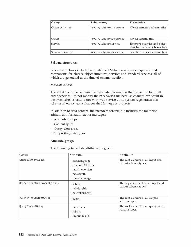
Group Subdirectory Description
Object Structure <root>/schema/common/mos Object structure schema files
Object <root>/schema/common/mbo Object schema files
Service <root>/schema/service Enterprise service and objectstructure service schema files
Standard service <root>/schema/service/ss Standard service schema files
Schema structures:
Schema structures include the predefined Metadata schema component andcomponents for objects, object structures, services and standard services, all ofwhich are generated at the time of schema creation
Metadata schema:
The MXMeta.xsd file contains the metadata information that is used to build allother schemas. Do not modify the MXMeta.xsd file because changes can result inincorrect schemas and issues with web services. The system regenerates thisschema when someone changes the Namespace property.
In addition to data content, the metadata schema file includes the followingadditional information about messages:v Attribute groupsv Content typesv Query data typesv Supporting data types
Attribute groups
The following table lists attributes by group.
Group Attributes Applies to
CommonContentGroup v baseLanguage
v creationDateTime
v maximoversion
v messageID
v transLanguage
The root element of all input andoutput schema types.
ObjectStructurePropertyGroup v action
v relationship
v deleteForInsert
The object element of all input andoutput schema types.
PublishingContentGroup v event The root element of all outputschema types.
QueryContentGroup v maxItems
v rsStart
v uniqueResult
The root element of all query inputschema types.
358 Integrating Data With External Applications
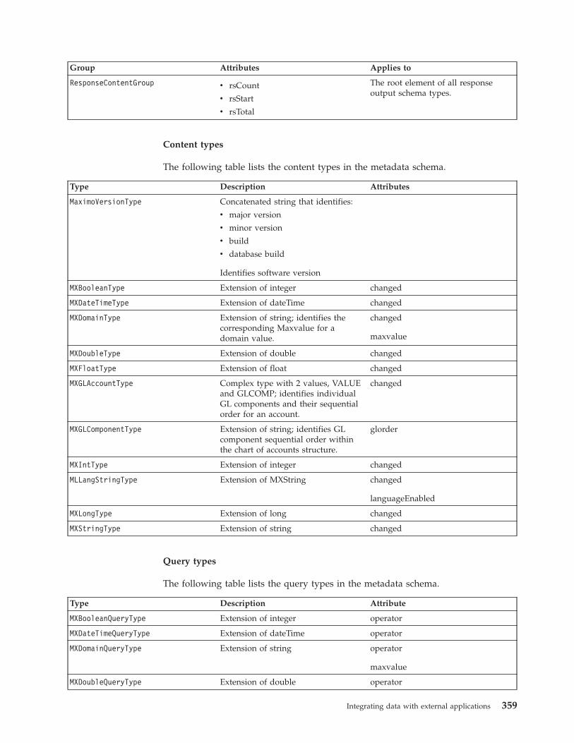
Group Attributes Applies to
ResponseContentGroup v rsCount
v rsStart
v rsTotal
The root element of all responseoutput schema types.
Content types
The following table lists the content types in the metadata schema.
Type Description Attributes
MaximoVersionType Concatenated string that identifies:
v major version
v minor version
v build
v database build
Identifies software version
MXBooleanType Extension of integer changed
MXDateTimeType Extension of dateTime changed
MXDomainType Extension of string; identifies thecorresponding Maxvalue for adomain value.
changed
maxvalue
MXDoubleType Extension of double changed
MXFloatType Extension of float changed
MXGLAccountType Complex type with 2 values, VALUEand GLCOMP; identifies individualGL components and their sequentialorder for an account.
changed
MXGLComponentType Extension of string; identifies GLcomponent sequential order withinthe chart of accounts structure.
glorder
MXIntType Extension of integer changed
MLLangStringType Extension of MXString changed
languageEnabled
MXLongType Extension of long changed
MXStringType Extension of string changed
Query types
The following table lists the query types in the metadata schema.
Type Description Attribute
MXBooleanQueryType Extension of integer operator
MXDateTimeQueryType Extension of dateTime operator
MXDomainQueryType Extension of string operator
maxvalue
MXDoubleQueryType Extension of double operator
Integrating data with external applications 359
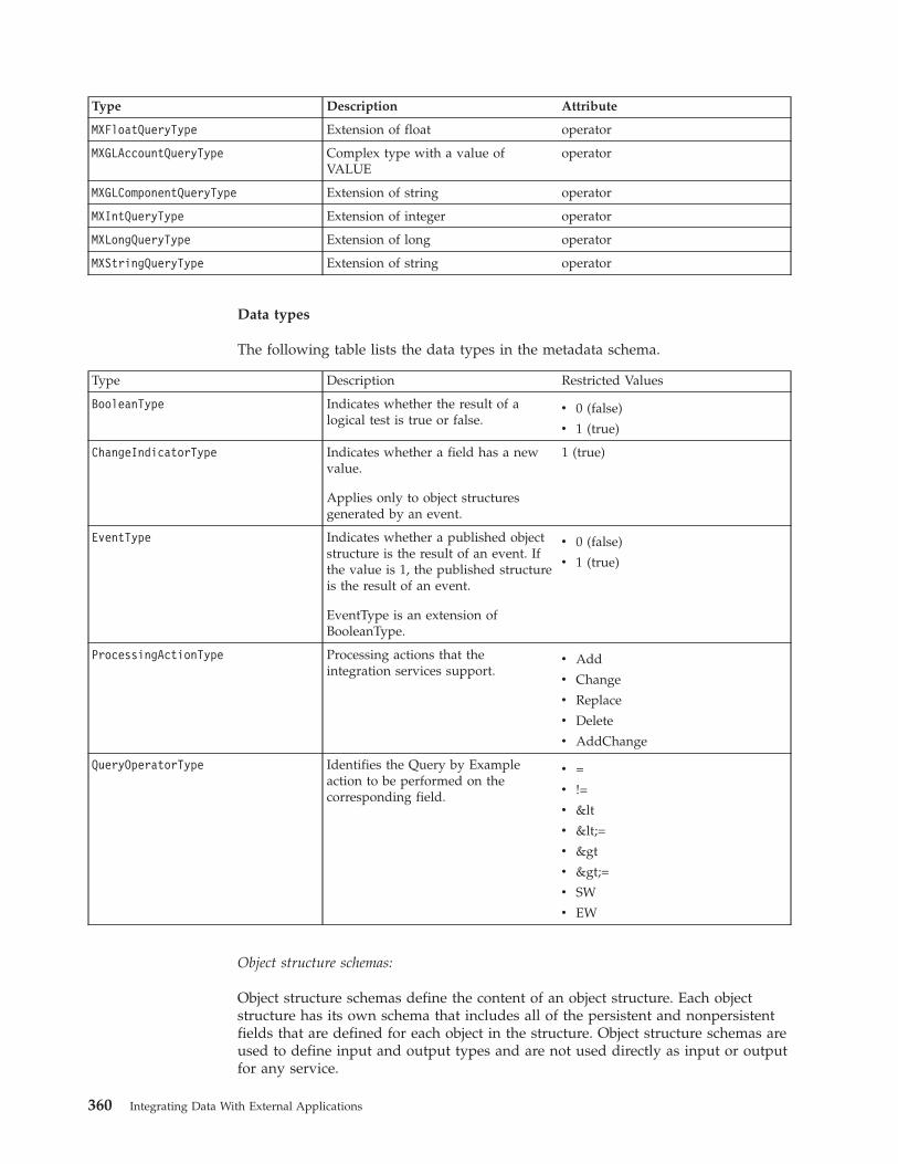
Type Description Attribute
MXFloatQueryType Extension of float operator
MXGLAccountQueryType Complex type with a value ofVALUE
operator
MXGLComponentQueryType Extension of string operator
MXIntQueryType Extension of integer operator
MXLongQueryType Extension of long operator
MXStringQueryType Extension of string operator
Data types
The following table lists the data types in the metadata schema.
Type Description Restricted Values
BooleanType Indicates whether the result of alogical test is true or false.
v 0 (false)
v 1 (true)
ChangeIndicatorType Indicates whether a field has a newvalue.
Applies only to object structuresgenerated by an event.
1 (true)
EventType Indicates whether a published objectstructure is the result of an event. Ifthe value is 1, the published structureis the result of an event.
EventType is an extension ofBooleanType.
v 0 (false)
v 1 (true)
ProcessingActionType Processing actions that theintegration services support.
v Add
v Change
v Replace
v Delete
v AddChange
QueryOperatorType Identifies the Query by Exampleaction to be performed on thecorresponding field.
v =
v !=
v <
v <=
v >
v >=
v SW
v EW
Object structure schemas:
Object structure schemas define the content of an object structure. Each objectstructure has its own schema that includes all of the persistent and nonpersistentfields that are defined for each object in the structure. Object structure schemas areused to define input and output types and are not used directly as input or outputfor any service.
360 Integrating Data With External Applications
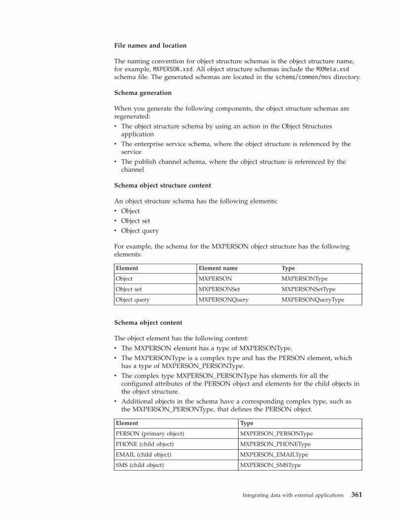
File names and location
The naming convention for object structure schemas is the object structure name,for example, MXPERSON.xsd. All object structure schemas include the MXMeta.xsdschema file. The generated schemas are located in the schema/common/mos directory.
Schema generation
When you generate the following components, the object structure schemas areregenerated:v The object structure schema by using an action in the Object Structures
applicationv The enterprise service schema, where the object structure is referenced by the
servicev The publish channel schema, where the object structure is referenced by the
channel
Schema object structure content
An object structure schema has the following elements:v Objectv Object setv Object query
For example, the schema for the MXPERSON object structure has the followingelements:
Element Element name Type
Object MXPERSON MXPERSONType
Object set MXPERSONSet MXPERSONSetType
Object query MXPERSONQuery MXPERSONQueryType
Schema object content
The object element has the following content:v The MXPERSON element has a type of MXPERSONType.v The MXPERSONType is a complex type and has the PERSON element, which
has a type of MXPERSON_PERSONType.v The complex type MXPERSON_PERSONType has elements for all the
configured attributes of the PERSON object and elements for the child objects inthe object structure.
v Additional objects in the schema have a corresponding complex type, such asthe MXPERSON_PERSONType, that defines the PERSON object.
Element Type
PERSON (primary object) MXPERSON_PERSONType
PHONE (child object) MXPERSON_PHONEType
EMAIL (child object) MXPERSON_EMAILType
SMS (child object) MXPERSON_SMSType
Integrating data with external applications 361
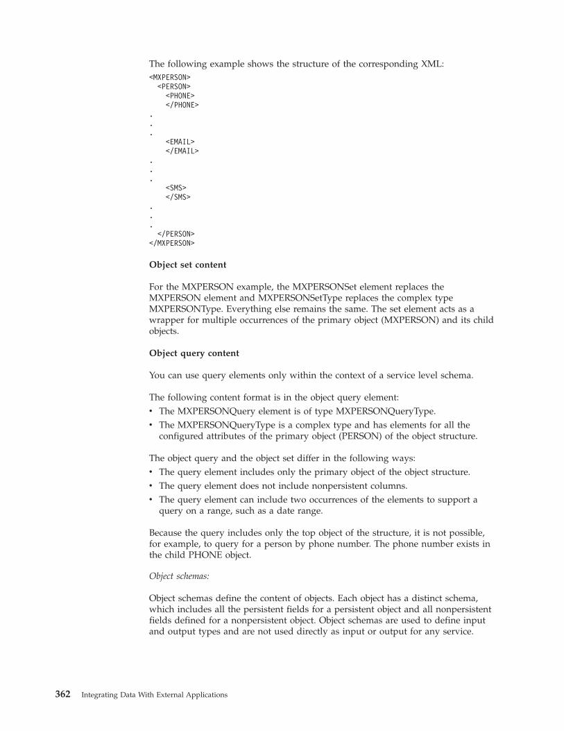
The following example shows the structure of the corresponding XML:<MXPERSON>
<PERSON><PHONE></PHONE>
.
.
.<EMAIL></EMAIL>
.
.
.<SMS></SMS>
.
.
.</PERSON>
</MXPERSON>
Object set content
For the MXPERSON example, the MXPERSONSet element replaces theMXPERSON element and MXPERSONSetType replaces the complex typeMXPERSONType. Everything else remains the same. The set element acts as awrapper for multiple occurrences of the primary object (MXPERSON) and its childobjects.
Object query content
You can use query elements only within the context of a service level schema.
The following content format is in the object query element:v The MXPERSONQuery element is of type MXPERSONQueryType.v The MXPERSONQueryType is a complex type and has elements for all the
configured attributes of the primary object (PERSON) of the object structure.
The object query and the object set differ in the following ways:v The query element includes only the primary object of the object structure.v The query element does not include nonpersistent columns.v The query element can include two occurrences of the elements to support a
query on a range, such as a date range.
Because the query includes only the top object of the structure, it is not possible,for example, to query for a person by phone number. The phone number exists inthe child PHONE object.
Object schemas:
Object schemas define the content of objects. Each object has a distinct schema,which includes all the persistent fields for a persistent object and all nonpersistentfields defined for a nonpersistent object. Object schemas are used to define inputand output types and are not used directly as input or output for any service.
362 Integrating Data With External Applications
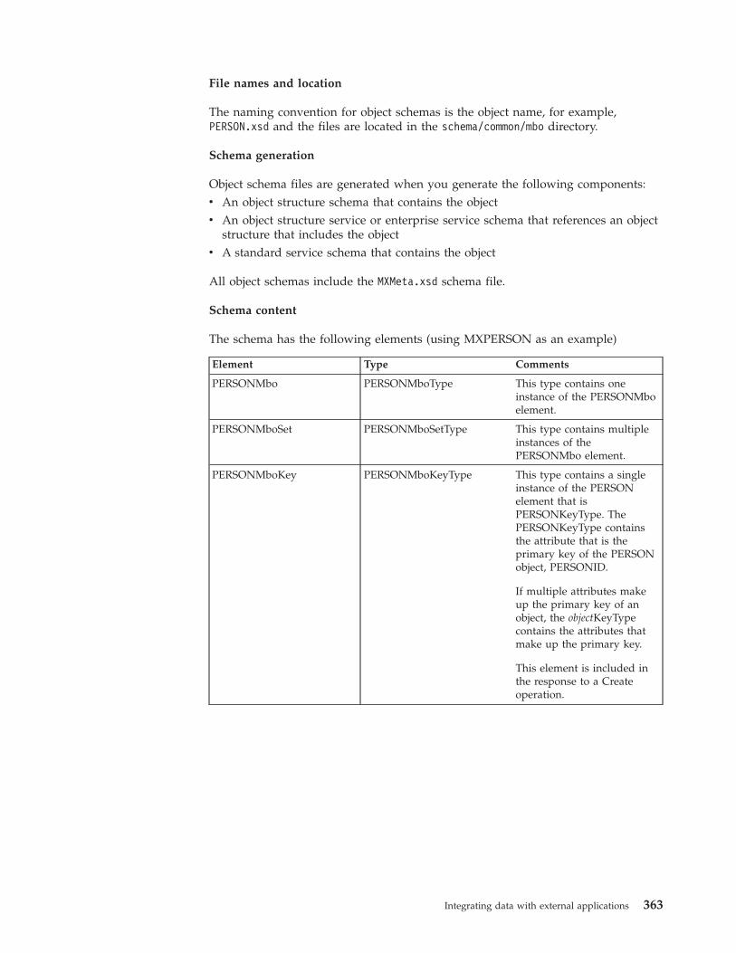
File names and location
The naming convention for object schemas is the object name, for example,PERSON.xsd and the files are located in the schema/common/mbo directory.
Schema generation
Object schema files are generated when you generate the following components:v An object structure schema that contains the objectv An object structure service or enterprise service schema that references an object
structure that includes the objectv A standard service schema that contains the object
All object schemas include the MXMeta.xsd schema file.
Schema content
The schema has the following elements (using MXPERSON as an example)
Element Type Comments
PERSONMbo PERSONMboType This type contains oneinstance of the PERSONMboelement.
PERSONMboSet PERSONMboSetType This type contains multipleinstances of thePERSONMbo element.
PERSONMboKey PERSONMboKeyType This type contains a singleinstance of the PERSONelement that isPERSONKeyType. ThePERSONKeyType containsthe attribute that is theprimary key of the PERSONobject, PERSONID.
If multiple attributes makeup the primary key of anobject, the objectKeyTypecontains the attributes thatmake up the primary key.
This element is included inthe response to a Createoperation.
Integrating data with external applications 363
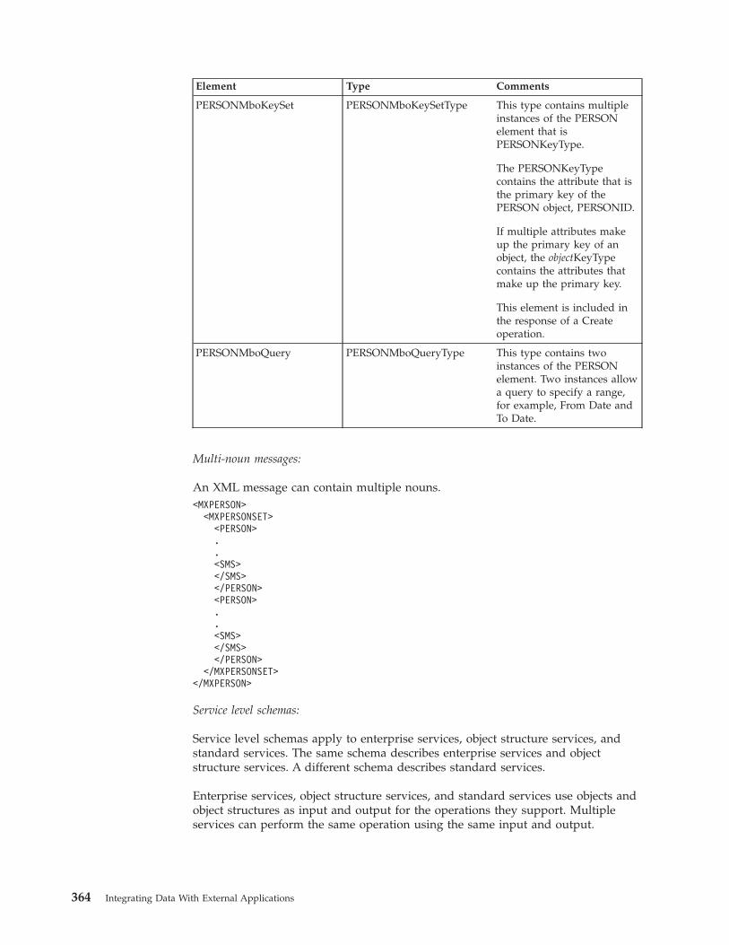
Element Type Comments
PERSONMboKeySet PERSONMboKeySetType This type contains multipleinstances of the PERSONelement that isPERSONKeyType.
The PERSONKeyTypecontains the attribute that isthe primary key of thePERSON object, PERSONID.
If multiple attributes makeup the primary key of anobject, the objectKeyTypecontains the attributes thatmake up the primary key.
This element is included inthe response of a Createoperation.
PERSONMboQuery PERSONMboQueryType This type contains twoinstances of the PERSONelement. Two instances allowa query to specify a range,for example, From Date andTo Date.
Multi-noun messages:
An XML message can contain multiple nouns.<MXPERSON>
<MXPERSONSET><PERSON>..<SMS></SMS></PERSON><PERSON>..<SMS></SMS></PERSON>
</MXPERSONSET></MXPERSON>
Service level schemas:
Service level schemas apply to enterprise services, object structure services, andstandard services. The same schema describes enterprise services and objectstructure services. A different schema describes standard services.
Enterprise services, object structure services, and standard services use objects andobject structures as input and output for the operations they support. Multipleservices can perform the same operation using the same input and output.
364 Integrating Data With External Applications
Predefined input and output for publish channels and invocation channels areused to implement these channels to invoke external services or to map to otheroutput formats.
File names and location
The naming convention for object structure schemas and enterprise servicesschemas is application service name + Service, for example, PERSONService.xsd wherePERSON is the application service name.
The naming convention for service level schemas is object structure + Service, forexample, MXPERSONService.xsd.
The schema files are located in the /schema/service directory.
The schema files are located in the <root>/schema/common/service directory.
Schema generation
Predefined service-level schema files are not provided. When you deploy a webservice, a service-level schema file is generated for the associated object structure, ifone does not exist. You can also generate a service-level schema by using an actionin the Web Services Library application
All service level schemas include the metadata schema file and the applicableobject structure and object schema files.
Schema content
One schema file is generated for each object structure with multiple data typeswithin each file. Each data type corresponds to each input and output operationthat can be deployed or processed as a service. Different services reuse the datatypes in these schemas. No one service uses all the data types in a single schema.
Service-level schemas contain the following types, using the MXPERSON example:v CreateMXPERSONv CreateMXPERSONResponsev DeleteMXPERSONv InvokeMXPERSONv InvokeMXPERSONResponsev PublishMXPERSONv QueryMXPERSONv QueryMXPERSONResponsev SyncMXPERSONv UpdateMXPERSON
Standard service schemas input and output:
Standard services are provided by applications to perform specific operations onobjects and can expose multiple methods as web services. Standard services areavailable only for methods that are properly annotated within the service.
The service-level schemas that are generated for standard services are used only bythe corresponding actions.
Integrating data with external applications 365
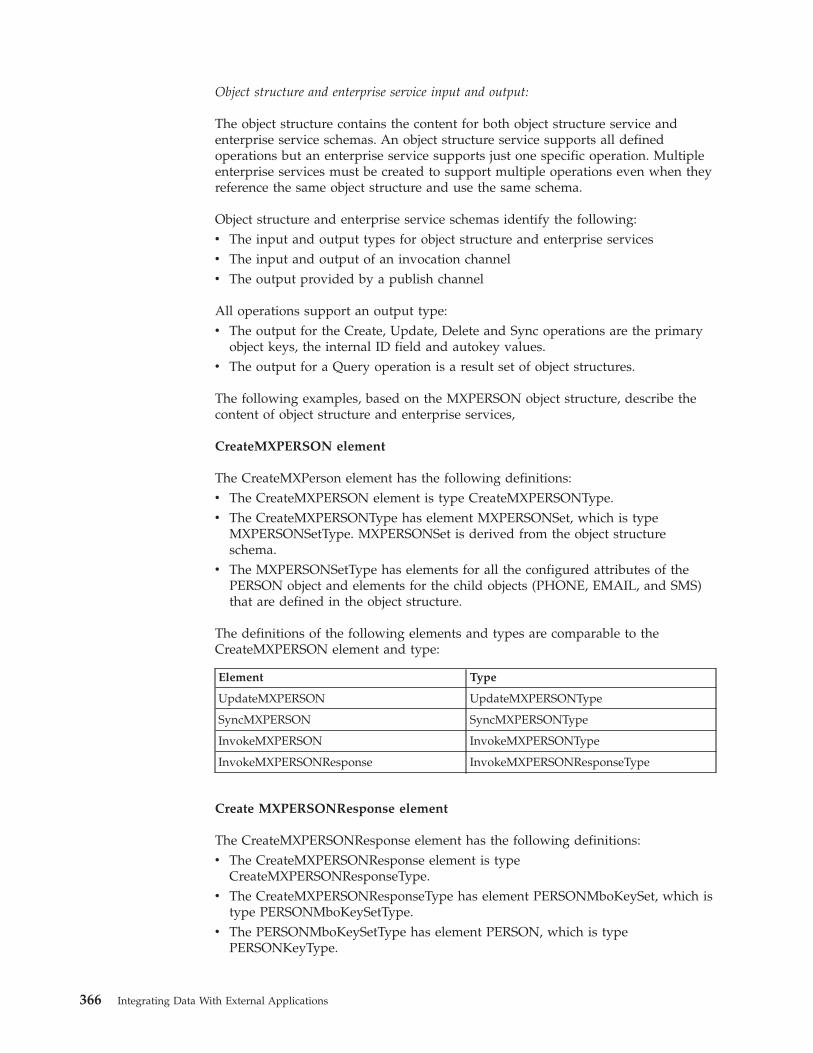
Object structure and enterprise service input and output:
The object structure contains the content for both object structure service andenterprise service schemas. An object structure service supports all definedoperations but an enterprise service supports just one specific operation. Multipleenterprise services must be created to support multiple operations even when theyreference the same object structure and use the same schema.
Object structure and enterprise service schemas identify the following:v The input and output types for object structure and enterprise servicesv The input and output of an invocation channelv The output provided by a publish channel
All operations support an output type:v The output for the Create, Update, Delete and Sync operations are the primary
object keys, the internal ID field and autokey values.v The output for a Query operation is a result set of object structures.
The following examples, based on the MXPERSON object structure, describe thecontent of object structure and enterprise services,
CreateMXPERSON element
The CreateMXPerson element has the following definitions:v The CreateMXPERSON element is type CreateMXPERSONType.v The CreateMXPERSONType has element MXPERSONSet, which is type
MXPERSONSetType. MXPERSONSet is derived from the object structureschema.
v The MXPERSONSetType has elements for all the configured attributes of thePERSON object and elements for the child objects (PHONE, EMAIL, and SMS)that are defined in the object structure.
The definitions of the following elements and types are comparable to theCreateMXPERSON element and type:
Element Type
UpdateMXPERSON UpdateMXPERSONType
SyncMXPERSON SyncMXPERSONType
InvokeMXPERSON InvokeMXPERSONType
InvokeMXPERSONResponse InvokeMXPERSONResponseType
Create MXPERSONResponse element
The CreateMXPERSONResponse element has the following definitions:v The CreateMXPERSONResponse element is type
CreateMXPERSONResponseType.v The CreateMXPERSONResponseType has element PERSONMboKeySet, which is
type PERSONMboKeySetType.v The PERSONMboKeySetType has element PERSON, which is type
PERSONKeyType.
366 Integrating Data With External Applications
v The PERSONKeyType contains only the PERSONID attribute of the PERSONobject, which is the primary key of the PERSON object.
PublishMXPERSON element
The PublishMXPERSON element has the following definitions:v The PublishMXPERSON element is type PublishMXPERSONType.v The PublishMXPERSONType has element MXPERSONSet, which is type
MXPERSONSetType. MXPERSONSet is derived from the object structureschema.
v MXPERSONSetType has elements for all the configured attributes of thePERSON object and for the child objects ((PHONE, EMAIL, and SMS) defined inthe object structure.
The Publish element is like the Create element but uses an additional attribute,event, that is defined in the PublishingContentGroup in the metadata schema.
DeleteMXPERSON element
The DeleteMXPERSON element has the following definitions:v The DeleteMXPERSON element is type DeleteMXPERSONType.v The DeleteMXPERSONType has element MXPERSONDelete, which is type
MXPERSONDeleteType.v The MXPERSONDeleteType has elements for all the configured attributes of the
PERSON object. Delete supports only the top (primary) object of the objectstructure.
QueryMXPERSON element
The QueryMXPERSON element has the following definitions:v The QueryMXPERSON element is type QueryMXPERSONType.v The QueryMXPERSONType has element MXPERSONQuery, which is type
MXPERSONQueryType.v The MXPERSONQueryType has elements for all the configured attributes of the
PERSON object. Query supports only querying against the top (primary) objectof the object structure.
The Query element uses the additional attributes uniqueResults, maxItems, andrsStart, which are defined in the QueryContentGroup in the metadata schema.
QueryMXPERSONResponse element
The QueryMXPERSONResponse element has the following definitions:v The QueryMXPERSONResponse element is type
QueryMXPERSONResponseType.v The QueryMXPERSONResponseType has element MXPERSONSet, which is type
MXPERSONSetType.v The MXPERSONSetType has elements for all the configured attributes of the
PERSON object and elements for child objects defined in the object structure(PHONE, EMAIL, and SMS).
v Although the QueryMXPERSON element restricts queries to the top object of theobject structure (PERSON), the response can contain child objects (PHONE,EMAIL, and SMS).
Integrating data with external applications 367
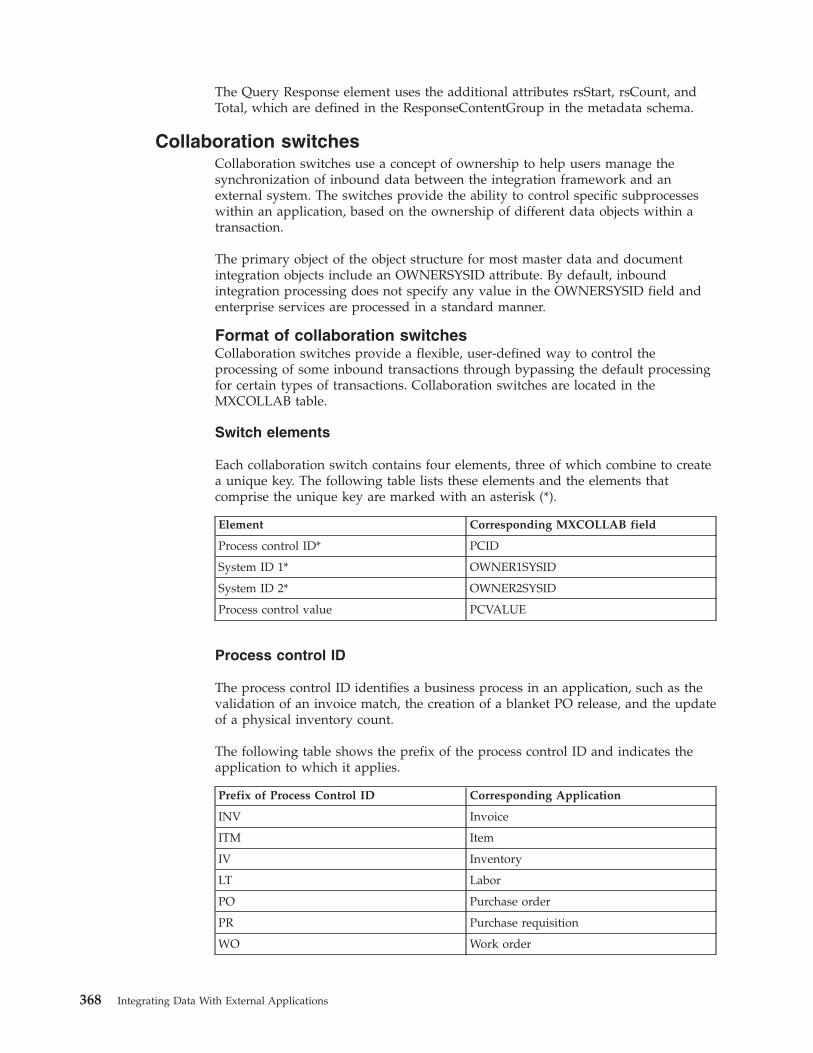
The Query Response element uses the additional attributes rsStart, rsCount, andTotal, which are defined in the ResponseContentGroup in the metadata schema.
Collaboration switchesCollaboration switches use a concept of ownership to help users manage thesynchronization of inbound data between the integration framework and anexternal system. The switches provide the ability to control specific subprocesseswithin an application, based on the ownership of different data objects within atransaction.
The primary object of the object structure for most master data and documentintegration objects include an OWNERSYSID attribute. By default, inboundintegration processing does not specify any value in the OWNERSYSID field andenterprise services are processed in a standard manner.
Format of collaboration switchesCollaboration switches provide a flexible, user-defined way to control theprocessing of some inbound transactions through bypassing the default processingfor certain types of transactions. Collaboration switches are located in theMXCOLLAB table.
Switch elements
Each collaboration switch contains four elements, three of which combine to createa unique key. The following table lists these elements and the elements thatcomprise the unique key are marked with an asterisk (*).
Element Corresponding MXCOLLAB field
Process control ID* PCID
System ID 1* OWNER1SYSID
System ID 2* OWNER2SYSID
Process control value PCVALUE
Process control ID
The process control ID identifies a business process in an application, such as thevalidation of an invoice match, the creation of a blanket PO release, and the updateof a physical inventory count.
The following table shows the prefix of the process control ID and indicates theapplication to which it applies.
Prefix of Process Control ID Corresponding Application
INV Invoice
ITM Item
IV Inventory
LT Labor
PO Purchase order
PR Purchase requisition
WO Work order
368 Integrating Data With External Applications
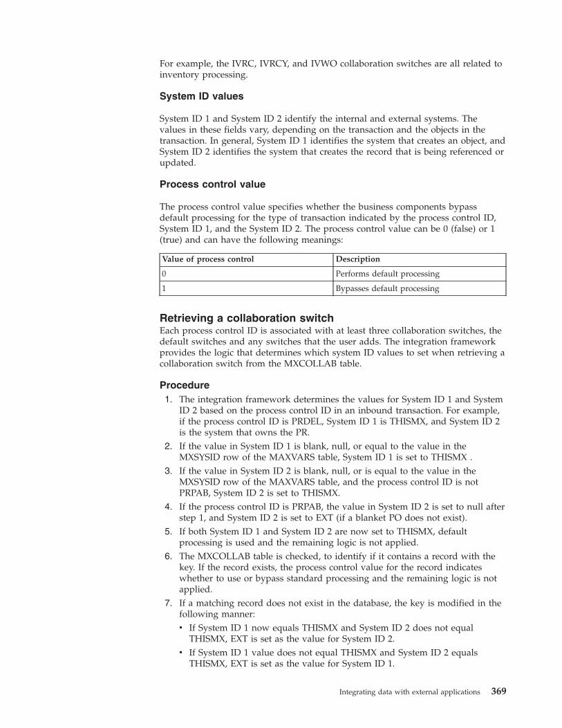
For example, the IVRC, IVRCY, and IVWO collaboration switches are all related toinventory processing.
System ID values
System ID 1 and System ID 2 identify the internal and external systems. Thevalues in these fields vary, depending on the transaction and the objects in thetransaction. In general, System ID 1 identifies the system that creates an object, andSystem ID 2 identifies the system that creates the record that is being referenced orupdated.
Process control value
The process control value specifies whether the business components bypassdefault processing for the type of transaction indicated by the process control ID,System ID 1, and the System ID 2. The process control value can be 0 (false) or 1(true) and can have the following meanings:
Value of process control Description
0 Performs default processing
1 Bypasses default processing
Retrieving a collaboration switchEach process control ID is associated with at least three collaboration switches, thedefault switches and any switches that the user adds. The integration frameworkprovides the logic that determines which system ID values to set when retrieving acollaboration switch from the MXCOLLAB table.
Procedure1. The integration framework determines the values for System ID 1 and System
ID 2 based on the process control ID in an inbound transaction. For example,if the process control ID is PRDEL, System ID 1 is THISMX, and System ID 2is the system that owns the PR.
2. If the value in System ID 1 is blank, null, or equal to the value in theMXSYSID row of the MAXVARS table, System ID 1 is set to THISMX .
3. If the value in System ID 2 is blank, null, or is equal to the value in theMXSYSID row of the MAXVARS table, and the process control ID is notPRPAB, System ID 2 is set to THISMX.
4. If the process control ID is PRPAB, the value in System ID 2 is set to null afterstep 1, and System ID 2 is set to EXT (if a blanket PO does not exist).
5. If both System ID 1 and System ID 2 are now set to THISMX, defaultprocessing is used and the remaining logic is not applied.
6. The MXCOLLAB table is checked, to identify if it contains a record with thekey. If the record exists, the process control value for the record indicateswhether to use or bypass standard processing and the remaining logic is notapplied.
7. If a matching record does not exist in the database, the key is modified in thefollowing manner:v If System ID 1 now equals THISMX and System ID 2 does not equal
THISMX, EXT is set as the value for System ID 2.v If System ID 1 value does not equal THISMX and System ID 2 equals
THISMX, EXT is set as the value for System ID 1.
Integrating data with external applications 369
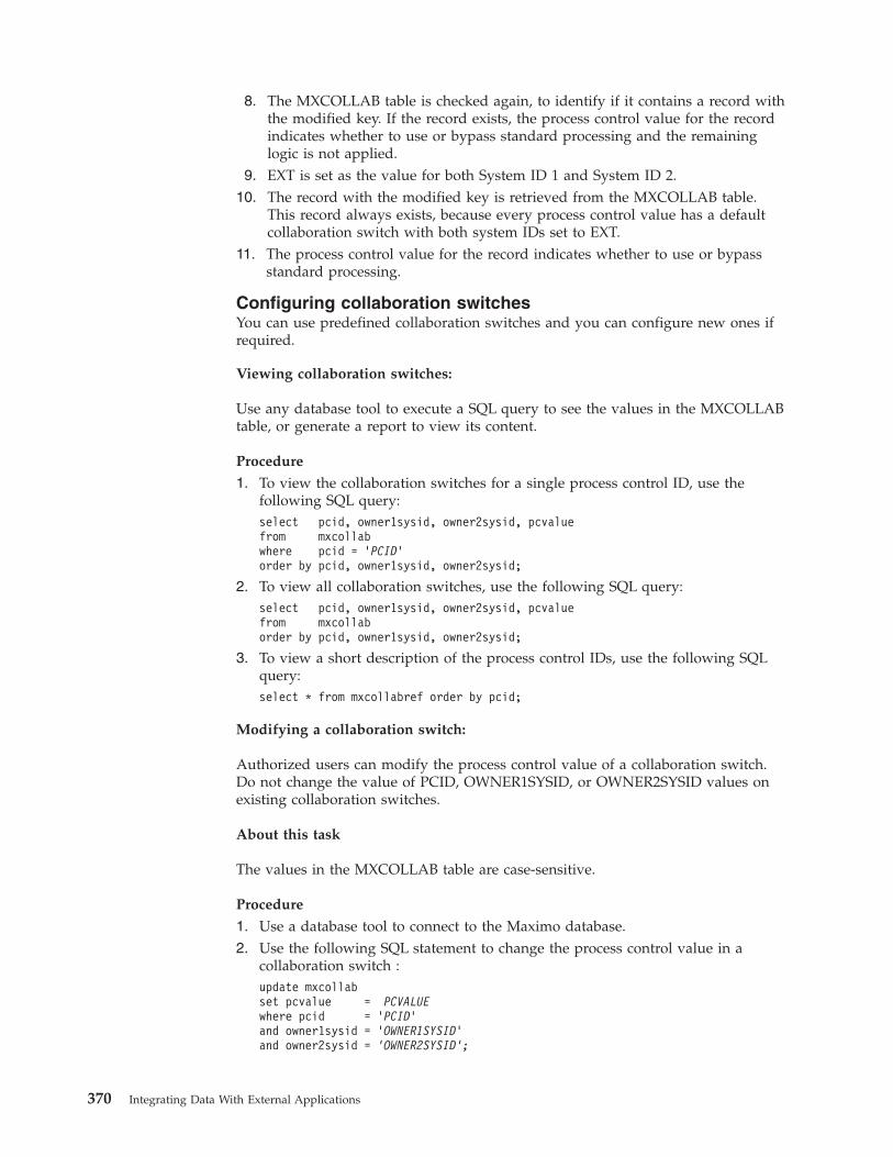
8. The MXCOLLAB table is checked again, to identify if it contains a record withthe modified key. If the record exists, the process control value for the recordindicates whether to use or bypass standard processing and the remaininglogic is not applied.
9. EXT is set as the value for both System ID 1 and System ID 2.10. The record with the modified key is retrieved from the MXCOLLAB table.
This record always exists, because every process control value has a defaultcollaboration switch with both system IDs set to EXT.
11. The process control value for the record indicates whether to use or bypassstandard processing.
Configuring collaboration switchesYou can use predefined collaboration switches and you can configure new ones ifrequired.
Viewing collaboration switches:
Use any database tool to execute a SQL query to see the values in the MXCOLLABtable, or generate a report to view its content.
Procedure
1. To view the collaboration switches for a single process control ID, use thefollowing SQL query:select pcid, owner1sysid, owner2sysid, pcvaluefrom mxcollabwhere pcid = ’PCID’order by pcid, owner1sysid, owner2sysid;
2. To view all collaboration switches, use the following SQL query:select pcid, owner1sysid, owner2sysid, pcvaluefrom mxcollaborder by pcid, owner1sysid, owner2sysid;
3. To view a short description of the process control IDs, use the following SQLquery:select * from mxcollabref order by pcid;
Modifying a collaboration switch:
Authorized users can modify the process control value of a collaboration switch.Do not change the value of PCID, OWNER1SYSID, or OWNER2SYSID values onexisting collaboration switches.
About this task
The values in the MXCOLLAB table are case-sensitive.
Procedure
1. Use a database tool to connect to the Maximo database.2. Use the following SQL statement to change the process control value in a
collaboration switch :update mxcollabset pcvalue = PCVALUEwhere pcid = 'PCID'and owner1sysid = 'OWNER1SYSID'and owner2sysid = 'OWNER2SYSID';
370 Integrating Data With External Applications
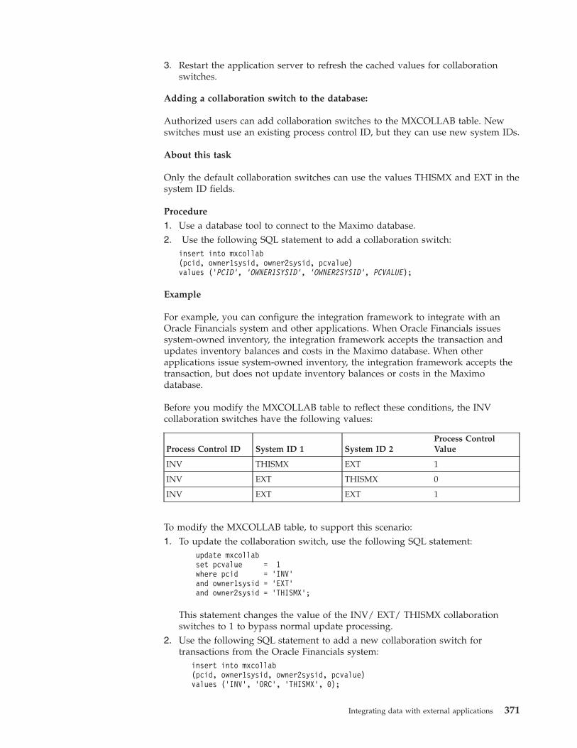
3. Restart the application server to refresh the cached values for collaborationswitches.
Adding a collaboration switch to the database:
Authorized users can add collaboration switches to the MXCOLLAB table. Newswitches must use an existing process control ID, but they can use new system IDs.
About this task
Only the default collaboration switches can use the values THISMX and EXT in thesystem ID fields.
Procedure
1. Use a database tool to connect to the Maximo database.2. Use the following SQL statement to add a collaboration switch:
insert into mxcollab(pcid, owner1sysid, owner2sysid, pcvalue)values ('PCID', 'OWNER1SYSID', 'OWNER2SYSID', PCVALUE);
Example
For example, you can configure the integration framework to integrate with anOracle Financials system and other applications. When Oracle Financials issuessystem-owned inventory, the integration framework accepts the transaction andupdates inventory balances and costs in the Maximo database. When otherapplications issue system-owned inventory, the integration framework accepts thetransaction, but does not update inventory balances or costs in the Maximodatabase.
Before you modify the MXCOLLAB table to reflect these conditions, the INVcollaboration switches have the following values:
Process Control ID System ID 1 System ID 2Process ControlValue
INV THISMX EXT 1
INV EXT THISMX 0
INV EXT EXT 1
To modify the MXCOLLAB table, to support this scenario:1. To update the collaboration switch, use the following SQL statement:
update mxcollabset pcvalue = 1where pcid = ’INV’and owner1sysid = ’EXT’and owner2sysid = ’THISMX’;
This statement changes the value of the INV/ EXT/ THISMX collaborationswitches to 1 to bypass normal update processing.
2. Use the following SQL statement to add a new collaboration switch fortransactions from the Oracle Financials system:
insert into mxcollab(pcid, owner1sysid, owner2sysid, pcvalue)values (’INV’, ’ORC’, ’THISMX’, 0);
Integrating data with external applications 371
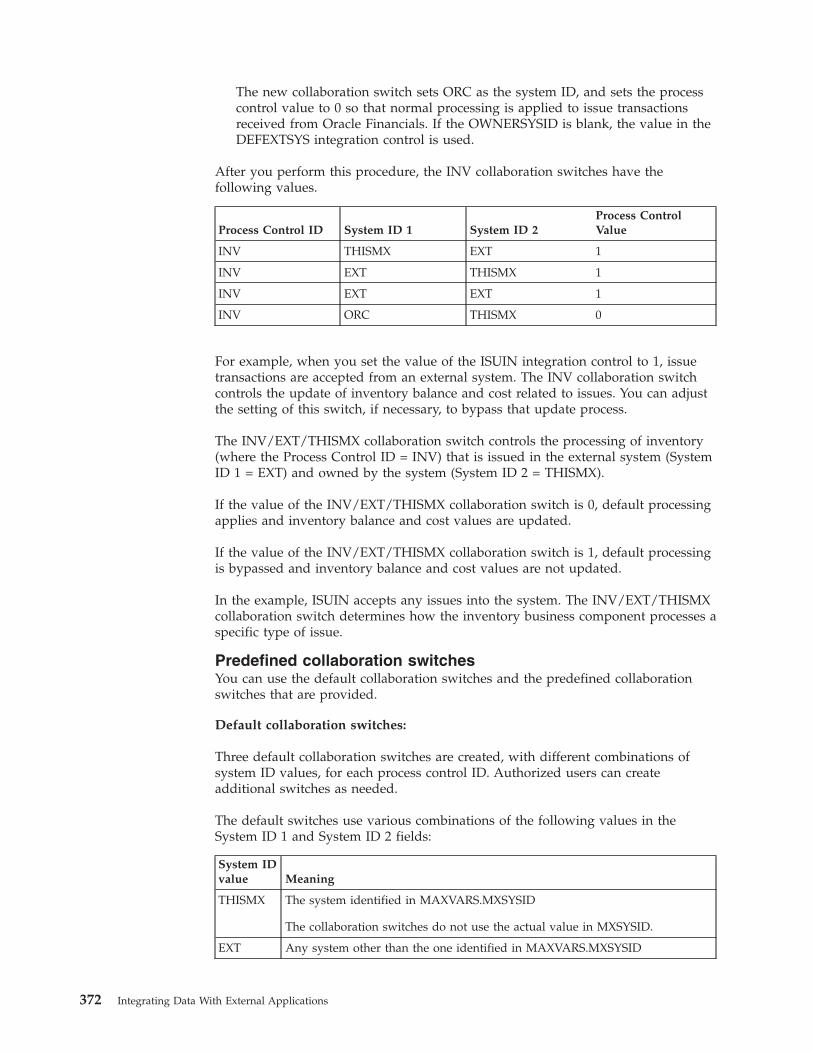
The new collaboration switch sets ORC as the system ID, and sets the processcontrol value to 0 so that normal processing is applied to issue transactionsreceived from Oracle Financials. If the OWNERSYSID is blank, the value in theDEFEXTSYS integration control is used.
After you perform this procedure, the INV collaboration switches have thefollowing values.
Process Control ID System ID 1 System ID 2Process ControlValue
INV THISMX EXT 1
INV EXT THISMX 1
INV EXT EXT 1
INV ORC THISMX 0
For example, when you set the value of the ISUIN integration control to 1, issuetransactions are accepted from an external system. The INV collaboration switchcontrols the update of inventory balance and cost related to issues. You can adjustthe setting of this switch, if necessary, to bypass that update process.
The INV/EXT/THISMX collaboration switch controls the processing of inventory(where the Process Control ID = INV) that is issued in the external system (SystemID 1 = EXT) and owned by the system (System ID 2 = THISMX).
If the value of the INV/EXT/THISMX collaboration switch is 0, default processingapplies and inventory balance and cost values are updated.
If the value of the INV/EXT/THISMX collaboration switch is 1, default processingis bypassed and inventory balance and cost values are not updated.
In the example, ISUIN accepts any issues into the system. The INV/EXT/THISMXcollaboration switch determines how the inventory business component processes aspecific type of issue.
Predefined collaboration switchesYou can use the default collaboration switches and the predefined collaborationswitches that are provided.
Default collaboration switches:
Three default collaboration switches are created, with different combinations ofsystem ID values, for each process control ID. Authorized users can createadditional switches as needed.
The default switches use various combinations of the following values in theSystem ID 1 and System ID 2 fields:
System IDvalue Meaning
THISMX The system identified in MAXVARS.MXSYSID
The collaboration switches do not use the actual value in MXSYSID.
EXT Any system other than the one identified in MAXVARS.MXSYSID
372 Integrating Data With External Applications
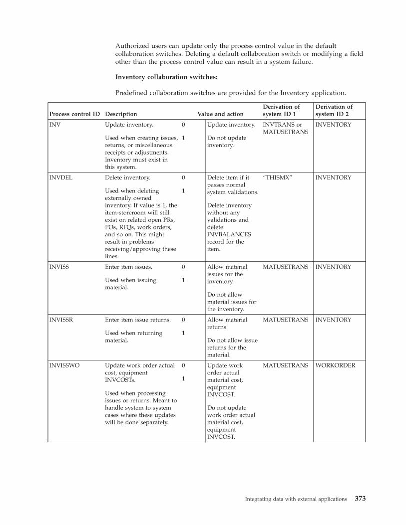
Authorized users can update only the process control value in the defaultcollaboration switches. Deleting a default collaboration switch or modifying a fieldother than the process control value can result in a system failure.
Inventory collaboration switches:
Predefined collaboration switches are provided for the Inventory application.
Process control ID Description Value and actionDerivation ofsystem ID 1
Derivation ofsystem ID 2
INV Update inventory.
Used when creating issues,returns, or miscellaneousreceipts or adjustments.Inventory must exist inthis system.
0
1
Update inventory.
Do not updateinventory.
INVTRANS orMATUSETRANS
INVENTORY
INVDEL Delete inventory.
Used when deletingexternally ownedinventory. If value is 1, theitem-storeroom will stillexist on related open PRs,POs, RFQs, work orders,and so on. This mightresult in problemsreceiving/approving theselines.
0
1
Delete item if itpasses normalsystem validations.
Delete inventorywithout anyvalidations anddeleteINVBALANCESrecord for theitem.
“THISMX” INVENTORY
INVISS Enter item issues.
Used when issuingmaterial.
0
1
Allow materialissues for theinventory.
Do not allowmaterial issues forthe inventory.
MATUSETRANS INVENTORY
INVISSR Enter item issue returns.
Used when returningmaterial.
0
1
Allow materialreturns.
Do not allow issuereturns for thematerial.
MATUSETRANS INVENTORY
INVISSWO Update work order actualcost, equipmentINVCOSTs.
Used when processingissues or returns. Meant tohandle system to systemcases where these updateswill be done separately.
0
1
Update workorder actualmaterial cost,equipmentINVCOST.
Do not updatework order actualmaterial cost,equipmentINVCOST.
MATUSETRANS WORKORDER
Integrating data with external applications 373
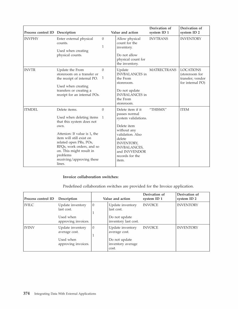
Process control ID Description Value and actionDerivation ofsystem ID 1
Derivation ofsystem ID 2
INVPHY Enter external physicalcounts.
Used when creatingphysical counts.
0
1
Allow physicalcount for theinventory.
Do not allowphysical count forthe inventory.
INVTRANS INVENTORY
INVTR Update the Fromstoreroom on a transfer orthe receipt of internal PO.
Used when creatingtransfers or creating areceipt for an internal POs.
0
1
UpdateINVBALANCES inthe Fromstoreroom.
Do not updateINVBALANCES inthe Fromstoreroom.
MATRECTRANS LOCATIONS(storeroom fortransfer; vendorfor internal PO)
ITMDEL Delete items.
Used when deleting itemsthat this system does notown.
Attenion: If value is 1, theitem will still exist onrelated open PRs, POs,RFQs, work orders, and soon. This might result inproblemsreceiving/approving theselines.
0
1
Delete item if itpasses normalsystem validations.
Delete itemwithout anyvalidation. AlsodeleteINVENTORY,INVBALANCES,and INVVENDORrecords for theitem.
“THISMX” ITEM
Invoice collaboration switches:
Predefined collaboration switches are provided for the Invoice application.
Process control ID Description Value and actionDerivation ofsystem ID 1
Derivation ofsystem ID 2
IVILC Update inventorylast cost.
Used whenapproving invoices.
0
1
Update inventorylast cost.
Do not updateinventory last cost.
INVOICE INVENTORY
IVINV Update inventoryaverage cost.
Used whenapproving invoices.
0
1
Update inventoryaverage cost.
Do not updateinventory averagecost.
INVOICE INVENTORY
374 Integrating Data With External Applications
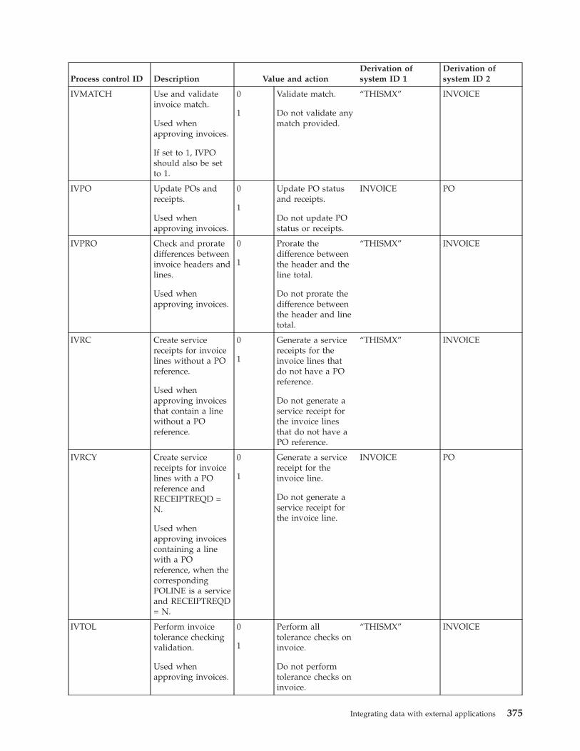
Process control ID Description Value and actionDerivation ofsystem ID 1
Derivation ofsystem ID 2
IVMATCH Use and validateinvoice match.
Used whenapproving invoices.
If set to 1, IVPOshould also be setto 1.
0
1
Validate match.
Do not validate anymatch provided.
“THISMX” INVOICE
IVPO Update POs andreceipts.
Used whenapproving invoices.
0
1
Update PO statusand receipts.
Do not update POstatus or receipts.
INVOICE PO
IVPRO Check and proratedifferences betweeninvoice headers andlines.
Used whenapproving invoices.
0
1
Prorate thedifference betweenthe header and theline total.
Do not prorate thedifference betweenthe header and linetotal.
“THISMX” INVOICE
IVRC Create servicereceipts for invoicelines without a POreference.
Used whenapproving invoicesthat contain a linewithout a POreference.
0
1
Generate a servicereceipts for theinvoice lines thatdo not have a POreference.
Do not generate aservice receipt forthe invoice linesthat do not have aPO reference.
“THISMX” INVOICE
IVRCY Create servicereceipts for invoicelines with a POreference andRECEIPTREQD =N.
Used whenapproving invoicescontaining a linewith a POreference, when thecorrespondingPOLINE is a serviceand RECEIPTREQD= N.
0
1
Generate a servicereceipt for theinvoice line.
Do not generate aservice receipt forthe invoice line.
INVOICE PO
IVTOL Perform invoicetolerance checkingvalidation.
Used whenapproving invoices.
0
1
Perform alltolerance checks oninvoice.
Do not performtolerance checks oninvoice.
“THISMX” INVOICE
Integrating data with external applications 375
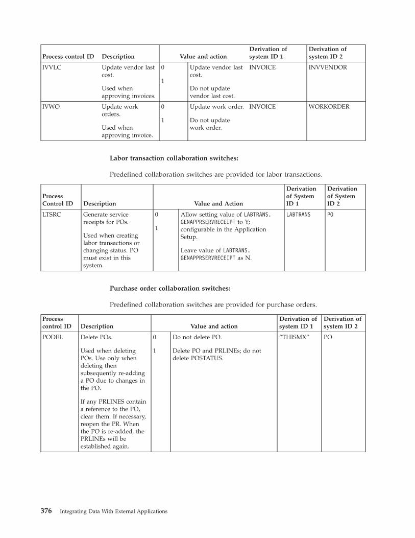
Process control ID Description Value and actionDerivation ofsystem ID 1
Derivation ofsystem ID 2
IVVLC Update vendor lastcost.
Used whenapproving invoices.
0
1
Update vendor lastcost.
Do not updatevendor last cost.
INVOICE INVVENDOR
IVWO Update workorders.
Used whenapproving invoice.
0
1
Update work order.
Do not updatework order.
INVOICE WORKORDER
Labor transaction collaboration switches:
Predefined collaboration switches are provided for labor transactions.
ProcessControl ID Description Value and Action
Derivationof SystemID 1
Derivationof SystemID 2
LTSRC Generate servicereceipts for POs.
Used when creatinglabor transactions orchanging status. POmust exist in thissystem.
0
1
Allow setting value of LABTRANS.GENAPPRSERVRECEIPT to Y;configurable in the ApplicationSetup.
Leave value of LABTRANS.GENAPPRSERVRECEIPT as N.
LABTRANS PO
Purchase order collaboration switches:
Predefined collaboration switches are provided for purchase orders.
Processcontrol ID Description Value and action
Derivation ofsystem ID 1
Derivation ofsystem ID 2
PODEL Delete POs.
Used when deletingPOs. Use only whendeleting thensubsequently re-addinga PO due to changes inthe PO.
If any PRLINES containa reference to the PO,clear them. If necessary,reopen the PR. Whenthe PO is re-added, thePRLINEs will beestablished again.
0
1
Do not delete PO.
Delete PO and PRLINEs; do notdelete POSTATUS.
“THISMX” PO
376 Integrating Data With External Applications
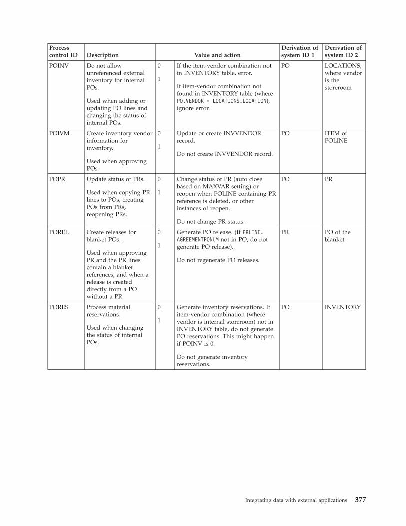
Processcontrol ID Description Value and action
Derivation ofsystem ID 1
Derivation ofsystem ID 2
POINV Do not allowunreferenced externalinventory for internalPOs.
Used when adding orupdating PO lines andchanging the status ofinternal POs.
0
1
If the item-vendor combination notin INVENTORY table, error.
If item-vendor combination notfound in INVENTORY table (wherePO.VENDOR = LOCATIONS.LOCATION),ignore error.
PO LOCATIONS,where vendoris thestoreroom
POIVM Create inventory vendorinformation forinventory.
Used when approvingPOs.
0
1
Update or create INVVENDORrecord.
Do not create INVVENDOR record.
PO ITEM ofPOLINE
POPR Update status of PRs.
Used when copying PRlines to POs, creatingPOs from PRs,reopening PRs.
0
1
Change status of PR (auto closebased on MAXVAR setting) orreopen when POLINE containing PRreference is deleted, or otherinstances of reopen.
Do not change PR status.
PO PR
POREL Create releases forblanket POs.
Used when approvingPR and the PR linescontain a blanketreferences, and when arelease is createddirectly from a POwithout a PR.
0
1
Generate PO release. (If PRLINE.AGREEMENTPONUM not in PO, do notgenerate PO release).
Do not regenerate PO releases.
PR PO of theblanket
PORES Process materialreservations.
Used when changingthe status of internalPOs.
0
1
Generate inventory reservations. Ifitem-vendor combination (wherevendor is internal storeroom) not inINVENTORY table, do not generatePO reservations. This might happenif POINV is 0.
Do not generate inventoryreservations.
PO INVENTORY
Integrating data with external applications 377
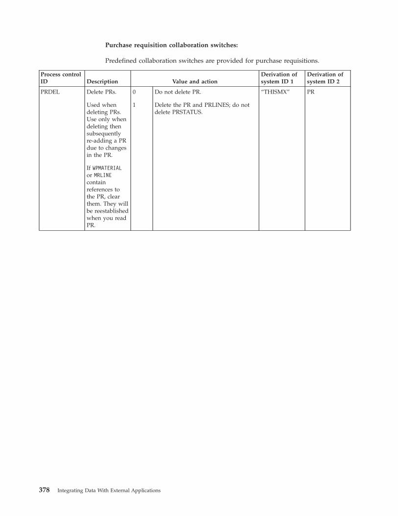
Purchase requisition collaboration switches:
Predefined collaboration switches are provided for purchase requisitions.
Process controlID Description Value and action
Derivation ofsystem ID 1
Derivation ofsystem ID 2
PRDEL Delete PRs.
Used whendeleting PRs.Use only whendeleting thensubsequentlyre-adding a PRdue to changesin the PR.
If WPMATERIALor MRLINEcontainreferences tothe PR, clearthem. They willbe reestablishedwhen you readPR.
0
1
Do not delete PR.
Delete the PR and PRLINES; do notdelete PRSTATUS.
“THISMX” PR
378 Integrating Data With External Applications
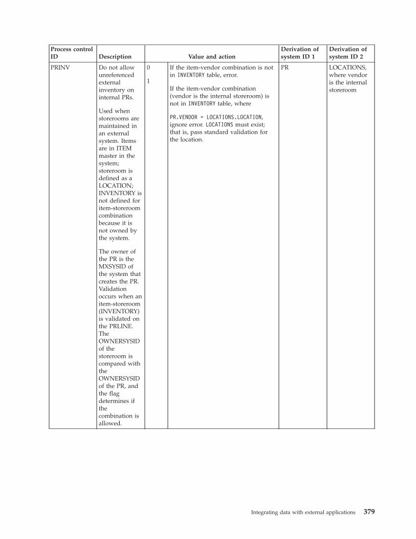
Process controlID Description Value and action
Derivation ofsystem ID 1
Derivation ofsystem ID 2
PRINV Do not allowunreferencedexternalinventory oninternal PRs.
Used whenstorerooms aremaintained inan externalsystem. Itemsare in ITEMmaster in thesystem;storeroom isdefined as aLOCATION;INVENTORY isnot defined foritem-storeroomcombinationbecause it isnot owned bythe system.
The owner ofthe PR is theMXSYSID ofthe system thatcreates the PR.Validationoccurs when anitem-storeroom(INVENTORY)is validated onthe PRLINE.TheOWNERSYSIDof thestoreroom iscompared withtheOWNERSYSIDof the PR, andthe flagdetermines ifthecombination isallowed.
0
1
If the item-vendor combination is notin INVENTORY table, error.
If the item-vendor combination(vendor is the internal storeroom) isnot in INVENTORY table, where
PR.VENDOR = LOCATIONS.LOCATION,ignore error. LOCATIONS must exist;that is, pass standard validation forthe location.
PR LOCATIONS,where vendoris the internalstoreroom
Integrating data with external applications 379
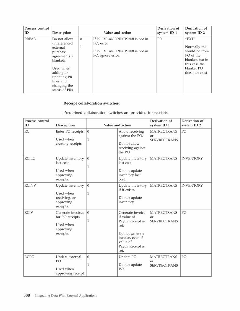
Process controlID Description Value and action
Derivation ofsystem ID 1
Derivation ofsystem ID 2
PRPAB Do not allowunreferencedexternalpurchaseagreements /blankets.
Used whenadding orupdating PRlines andchanging thestatus of PRs.
0
1
If PRLINE.AGREEMENTPONUM is not inPO, error.
If PRLINE.AGREEMENTPONUM is not inPO, ignore error.
PR “EXT”
Normally thiswould be fromPO of theblanket, but inthis case theblanket POdoes not exist
Receipt collaboration switches:
Predefined collaboration switches are provided for receipts.
Process controlID Description Value and action
Derivation ofsystem ID 1
Derivation ofsystem ID 2
RC Enter PO receipts.
Used whencreating receipts.
0
1
Allow receivingagainst the PO.
Do not allowreceiving againstthe PO.
MATRECTRANSorSERVRECTRANS
PO
RCILC Update inventorylast cost.
Used whenapprovingreceipts.
0
1
Update inventorylast cost.
Do not updateinventory lastcost.
MATRECTRANS INVENTORY
RCINV Update inventory.
Used whenreceiving, orapprovingreceipts.
0
1
Update inventoryif it exists.
Do not updateinventory.
MATRECTRANS INVENTORY
RCIV Generate invoicesfor PO receipts.
Used whenapprovingreceipts.
0
1
Generate invoiceif value ofPayOnReceipt isset.
Do not generateinvoice, even ifvalue ofPayOnReceipt isset.
MATRECTRANSorSERVRECTRANS
PO
RCPO Update externalPO.
Used whenapproving receipt.
0
1
Update PO.
Do not updatePO.
MATRECTRANSorSERVRECTRANS
PO
380 Integrating Data With External Applications
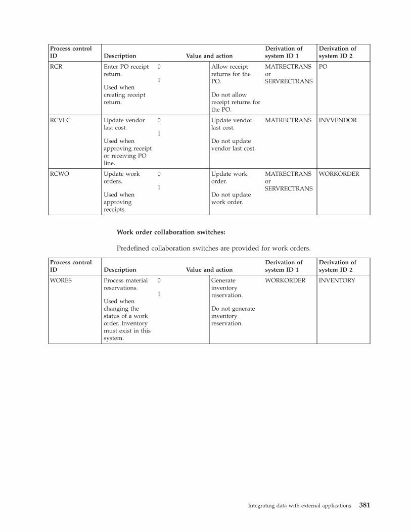
Process controlID Description Value and action
Derivation ofsystem ID 1
Derivation ofsystem ID 2
RCR Enter PO receiptreturn.
Used whencreating receiptreturn.
0
1
Allow receiptreturns for thePO.
Do not allowreceipt returns forthe PO.
MATRECTRANSorSERVRECTRANS
PO
RCVLC Update vendorlast cost.
Used whenapproving receiptor receiving POline.
0
1
Update vendorlast cost.
Do not updatevendor last cost.
MATRECTRANS INVVENDOR
RCWO Update workorders.
Used whenapprovingreceipts.
0
1
Update workorder.
Do not updatework order.
MATRECTRANSorSERVRECTRANS
WORKORDER
Work order collaboration switches:
Predefined collaboration switches are provided for work orders.
Process controlID Description Value and action
Derivation ofsystem ID 1
Derivation ofsystem ID 2
WORES Process materialreservations.
Used whenchanging thestatus of a workorder. Inventorymust exist in thissystem.
0
1
Generateinventoryreservation.
Do not generateinventoryreservation.
WORKORDER INVENTORY
Integrating data with external applications 381

382 Integrating Data With External Applications
Notices
This information was developed for products and services offered in the U.S.A.
IBM may not offer the products, services, or features discussed in this document inother countries. Consult your local IBM representative for information on theproducts and services currently available in your area. Any reference to an IBMproduct, program, or service is not intended to state or imply that only that IBMproduct, program, or service may be used. Any functionally equivalent product,program, or service that does not infringe any IBM intellectual property right maybe used instead. However, it is the user's responsibility to evaluate and verify theoperation of any non-IBM product, program, or service.
IBM may have patents or pending patent applications covering subject matterdescribed in this document. The furnishing of this document does not grant youany license to these patents. You can send license inquiries, in writing, to:
IBM Director of LicensingIBM CorporationNorth Castle DriveArmonk, NY 10504-1785U.S.A.
For license inquiries regarding double-byte (DBCS) information, contact the IBMIntellectual Property Department in your country or send inquiries, in writing, to:
Intellectual Property LicensingLegal and Intellectual Property LawIBM Japan Ltd.1623-14, Shimotsuruma, Yamato-shiKanagawa 242-8502 Japan
The following paragraph does not apply to the United Kingdom or any othercountry where such provisions are inconsistent with local law: INTERNATIONALBUSINESS MACHINES CORPORATION PROVIDES THIS PUBLICATION "AS IS"WITHOUT WARRANTY OF ANY KIND, EITHER EXPRESS OR IMPLIED,INCLUDING, BUT NOT LIMITED TO, THE IMPLIED WARRANTIES OFNON-INFRINGEMENT, MERCHANTABILITY OR FITNESS FOR A PARTICULARPURPOSE. Some states do not allow disclaimer of express or implied warranties incertain transactions, therefore, this statement may not apply to you.
This information could include technical inaccuracies or typographical errors.Changes are periodically made to the information herein; these changes will beincorporated in new editions of the publication. IBM may make improvementsand/or changes in the product(s) and/or the program(s) described in thispublication at any time without notice.
Any references in this information to non-IBM Web sites are provided forconvenience only and do not in any manner serve as an endorsement of thosewebsites. The materials at those websites are not part of the materials for this IBMproduct and use of those websites is at your own risk.
© Copyright IBM Corp. 2008, 2014 383
IBM may use or distribute any of the information you supply in any way itbelieves appropriate without incurring any obligation to you.
Licensees of this program who wish to have information about it for the purposeof enabling: (i) the exchange of information between independently createdprograms and other programs (including this one) and (ii) the mutual use of theinformation which has been exchanged, should contact:
IBM Corporation2Z4A/10111400 Burnet RoadAustin, TX 78758 U.S.A.
Such information may be available, subject to appropriate terms and conditions,including in some cases, payment of a fee.
The licensed program described in this document and all licensed materialavailable for it are provided by IBM under terms of the IBM Customer Agreement,IBM International Program License Agreement or any equivalent agreementbetween us.
Information concerning non-IBM products was obtained from the suppliers ofthose products, their published announcements or other publicly available sources.IBM has not tested those products and cannot confirm the accuracy ofperformance, compatibility or any other claims related to non-IBM products.Questions on the capabilities of non-IBM products should be addressed to thesuppliers of those products.
This information contains examples of data and reports used in daily businessoperations. To illustrate them as completely as possible, the examples include thenames of individuals, companies, brands, and products. All of these names arefictitious and any similarity to the names and addresses used by an actual businessenterprise is entirely coincidental.
COPYRIGHT LICENSE:
This information contains sample application programs in source language, whichillustrate programming techniques on various operating platforms. You may copy,modify, and distribute these sample programs in any form without payment toIBM, for the purposes of developing, using, marketing or distributing applicationprograms conforming to the application programming interface for the operatingplatform for which the sample programs are written. These examples have notbeen thoroughly tested under all conditions. IBM, therefore, cannot guarantee orimply reliability, serviceability, or function of these programs. The sampleprograms are provided "AS IS", without warranty of any kind. IBM shall not beliable for any damages arising out of your use of the sample programs.
TrademarksIBM, the IBM logo, and ibm.com are trademarks or registered trademarks ofInternational Business Machines Corp., registered in many jurisdictions worldwide.Other product and service names might be trademarks of IBM or other companies.A current list of IBM trademarks is available on the Web at “Copyright andtrademark information” at www.ibm.com/legal/copytrade.shtml.
384 Integrating Data With External Applications

Java and all Java-based trademarks and logos are trademarks or registeredtrademarks of Oracle and/or its affiliates.
Linux is a registered trademark of Linus Torvalds in the United States, othercountries, or both.
Microsoft, Windows, and the Windows logo are trademarks of MicrosoftCorporation in the United States, other countries, or both.
UNIX is a registered trademark of The Open Group in the United States and othercountries.
Notices 385

386 Integrating Data With External Applications


����
Printed in USA