integrating multiple microgrids into an active network management system
TRANSCRIPT

Integrating Multiple Microgrids into an Active Network Management System
Presented By: Colin Gault, Smarter Grid SolutionsCo-Authors: Joe Schatz, Southern Company
George Gao, Southern CompanyGeorge Simard, SIMARD SGBob Currie, Smarter Grid Solutions
February 3rd 2015

The “Project”
• Regional Microgrid Control: Research and Development
• Multi-year project between Southern Company and Smarter Grid Solutions
• Develop microgrid control platform using Active Network Management technology
• Phased Approach
– Phase 1: Use Case Definition and Simulation of Active Network Management (Complete February 2015)
– Phase 2: Trial deployment of Active Network Management at test site (Summer 2015)
– Future Phases: Phased implementation of microgrid functionality (2016)
2
Active Network Management
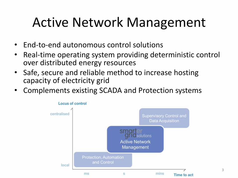
• End-to-end autonomous control solutions • Real-time operating system providing deterministic control
over distributed energy resources• Safe, secure and reliable method to increase hosting
capacity of electricity grid• Complements existing SCADA and Protection systems
3

Generator
DMS
Energy Storage System
GeneratorEnergy Storage System
DERMS
Data Historian
Active Network ManagementReliable - Deterministic - Repeatable
Scalable - Open Standards
4

Active Network Management
• Applied active network management to the following use cases in live deployments– Management of power flow constraints– Management of voltage constraints– Management of distributed generation contributing to transmission system
constraints– Smart electric vehicle charging– Demand Response (domestic / commercial)– Day ahead scheduling of controllable demand to coincide with renewable
energy production to support frequency stability
• Interfacing with range of Distributed Energy Resources– Wind | Solar | CHP |Building Management System | Electrical Energy Storage
Thermal Energy Storage | Electric Vehicle Charging Equipment
• Future development could include interoperability with automatic restoration and volt-var control solutions leveraging DER control
5

Generator
Energy Storage System
Circuit Microgrid
Generator
Facility Microgrid
Energy Storage System
Substation Microgrid
Microgrid Controller
Microgrid Controller
Microgrid Controller
DMS
ANM Application
DERMS
Data Historian
Adaptation to Incorporate MicrogridsNew layer of control: Microgrid Controller
6

Layers of Microgrid Control
7
Use Case Definition
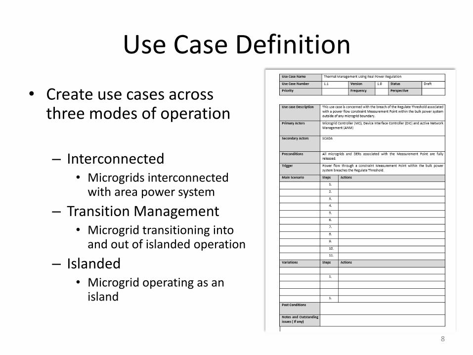
• Create use cases across three modes of operation
– Interconnected• Microgrids interconnected
with area power system
– Transition Management• Microgrid transitioning into
and out of islanded operation
– Islanded• Microgrid operating as an
island
8
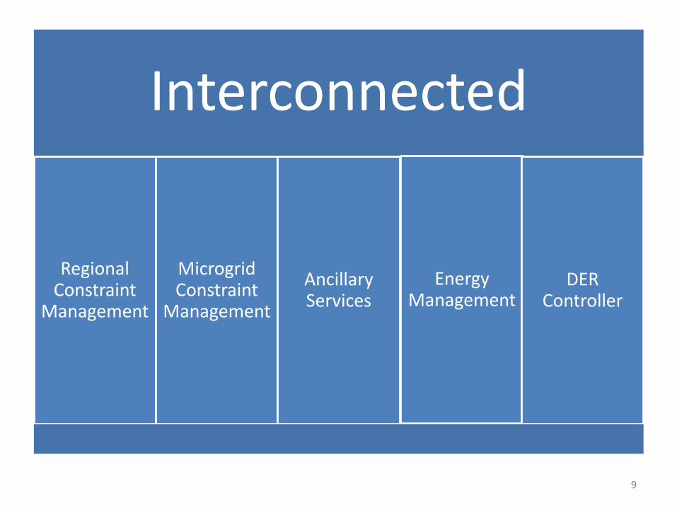
Interconnected
Regional Constraint
Management
Microgrid Constraint
Management
Ancillary Services
Energy Management
DER Controller
9
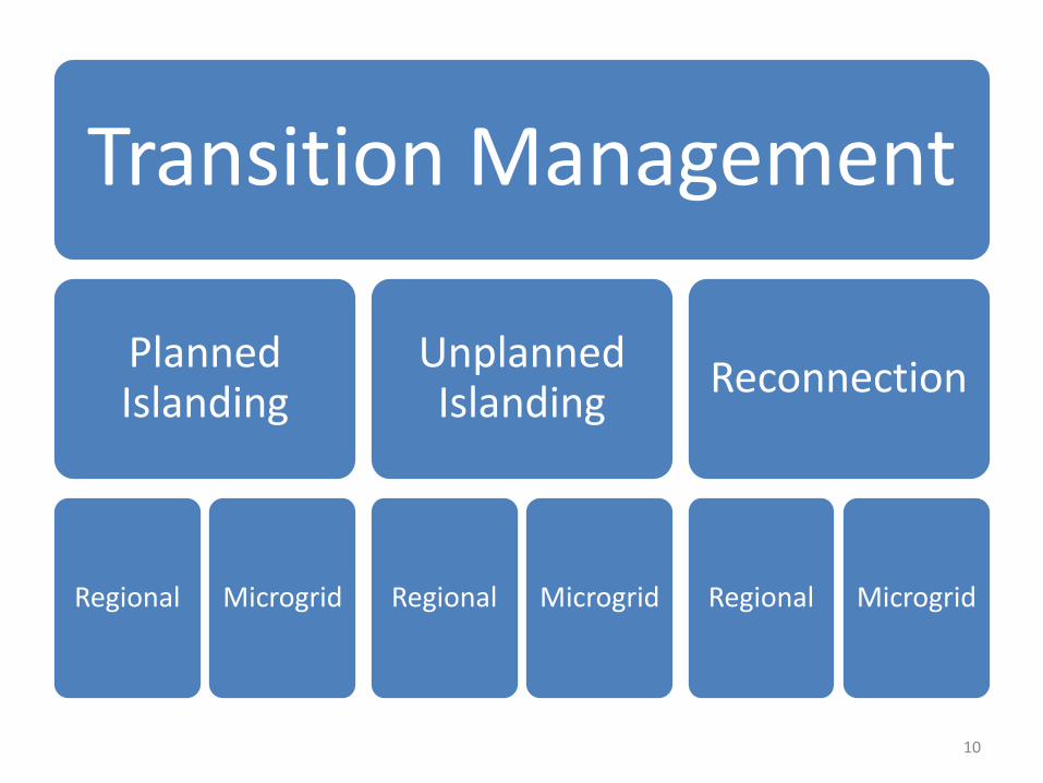
Transition Management
Planned Islanding
Regional Microgrid
Unplanned Islanding
Regional Microgrid
Reconnection
Regional Microgrid
10

Islanded
Frequency / Voltage Control
Energy Management
Black StartDER
Controller
11

1 MW Solar PV
1MW, 2MWh ESS
Modelling and Simulation
• Model of 12.47 kV Feeder with existing Solar PV: Peak demand 8MW
• Large proportion of feeder load is a single industrial customer
• Battery Energy Storage System to be installed later this year
• Steady State Load Flow simulations using CYMDIST
• Interconnected and Islanded Microgrid Use Cases Explored
12

1 MW Solar PV
1MW, 2MWh ESS
Feeder Demand
Measured at Substation
• Interconnected
– Use of the Energy Storage to minimize total feeder maximum demand
– Use of the energy Storage to minimize ratio between total feeder maximum and minimum demand
13
1 MW Solar PV
1MW, 2MWh ESS
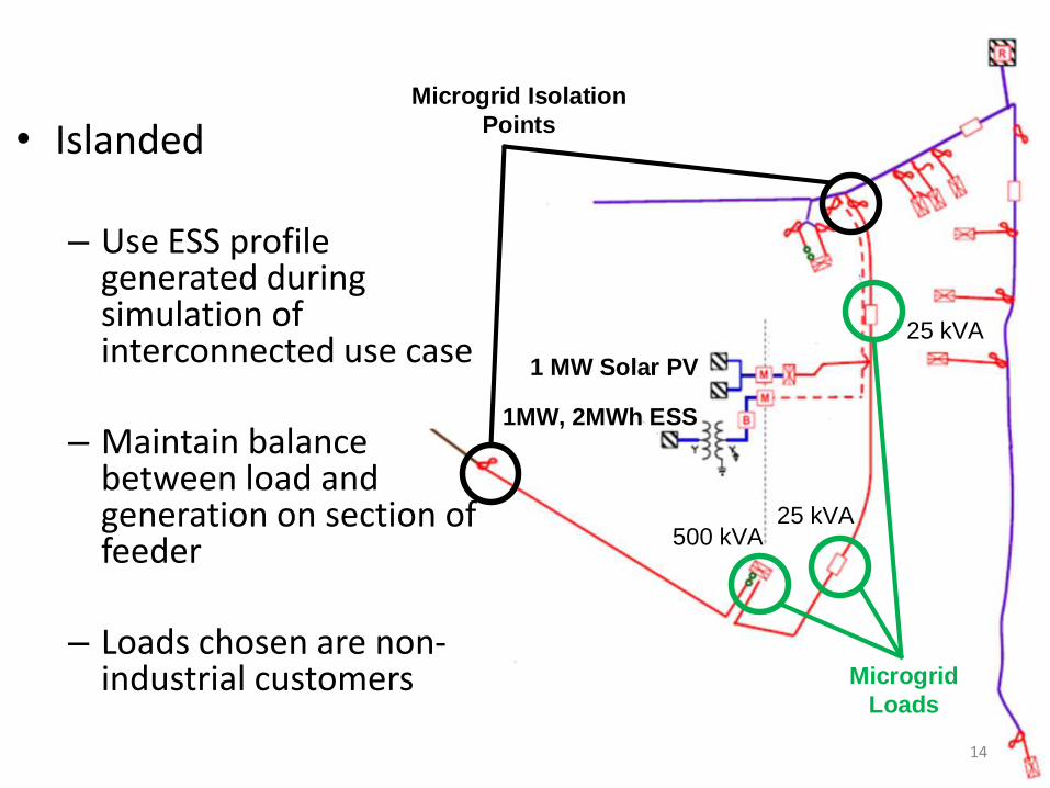
Microgrid Isolation
Points
Microgrid
Loads
25 kVA500 kVA
25 kVA
14
• Islanded
– Use ESS profile generated during simulation of interconnected use case
– Maintain balance between load and generation on section of feeder
– Loads chosen are non-industrial customers

1 MW Solar PV
1MW, 2MWh ESS
Microgrid Isolation
Points
Microgrid
Loads
25 kVA500 kVA
25 kVA
1500 kVA
15
• Extended Island
– Extend microgrid boundary
– Include additional load to stretch capability of microgrid resources

• Input Data– One year (2014) of hourly data for feeder
measured at substation
• Calculate “average day” profile for feeder
• Generate a 24 hour schedule for battery to reduce peaks and troughs and apply to 365 days
• Apply upper and lower thresholds that trigger unscheduled charge/discharge of battery
Method: Interconnected
16

• Starting position uses results from interconnected study
• For every hour in the year calculate the maximum duration that an island could be sustained if an “event” was to occur– Match Battery and PV to load on section of feeder
– Excess energy from PV charges battery
– Shortfall in PV discharges battery
• Assumes battery inverter has capability to maintain frequency and voltage stability
Method: Islanded
17

• Interconnected– Yearly peak demand reduced by 200 kW
– Yearly minimum demand increased by 150 kW
• Islanded: Peak load 500 kW– Islanding achievable 6888 hours out of 8760
– Average duration: 30 hours
• Extended Island: Peak load 2,000 kW– Islanding achievable 1584 hours out of 8760
– Average duration : 7.6 hours
Results
18

19
4
4.5
5
5.5
6
6.5
7
0 2 4 6 8 10 12 14 16 18 20 22 24
Typical Day
Original Profle (MW) With Battery (MW)
-2
-1.5
-1
-0.5
0
0.5
1
1.5
2
-0.3
-0.2
-0.1
0
0.1
0.2
0.3
0 2 4 6 8 10 12 14 16 18 20 22 24
Battery Profile
Final SOC (MWh) Final Power Profile (MW)
• Shape of profile with long peaks and deep troughs makes it difficult for battery to reduce peak and increase trough significantly during interconnected mode when following a daily schedule
• May be more appropriate to use battery during instantaneous events using triggers as opposed to implementing daily schedule
• Islanding results show promise in being able to sustain a microgrid for significant period of time to reduce interruptions to non-industrial customers on feeder
Conclusions
20

Project Next Steps
• Deploy Active Network Management solution to perform field trial of use cases and compare results
• Phased roll-out of microgrid functionality at pilot site and/or other appropriate sites and development of inter microgrid control philosophies
21
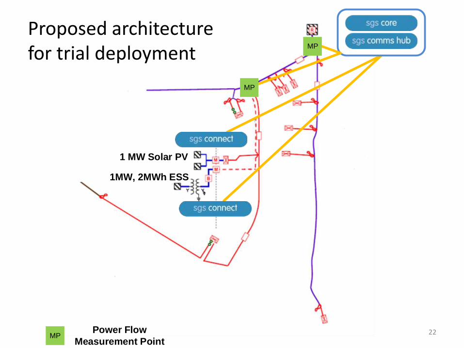
1 MW Solar PV
1MW, 2MWh ESS
MP
MP
MPPower Flow
Measurement Point22
Proposed architecture for trial deployment

Presented by: Colin Gault, Principal Consultant, Smarter Grid Solutions
E-mail: [email protected]: +1 (718) 260 3603
23