integrating a new software tool used for tool path
TRANSCRIPT

*Corr. Author’s Address: Transilvania University of Brasov, Department of Manufacturing Engineering, Mihai Viteazul 5, Brasov, Romania, [email protected] 643
Strojniški vestnik - Journal of Mechanical Engineering 64(2018)10, 643-651 Received for review: 2018-05-03© 2018 Journal of Mechanical Engineering. All rights reserved. Received revised form: 2018-06-27DOI:10.5545/sv-jme.2018.5475 Original Scientific Paper Accepted for publication: 2018-08-13
0 INTRODUCTION
In recent years, flexible manufacturing processes have gained increased attention from researchers and producers. Incremental sheet forming (ISF) is a “die-less” and flexible manufacturing process from the cold-pressing industry, used for customized products, rapid prototyping, and small batch production series of sheet metal parts [1] and [2].
The ISF working principle presented in Fig. 1 entails the sheet metal blank mounted on a fixing device consisting of a blank holder with or without a backing plate to support the part flange, and a clamping plate which is placed over the blank, fixing it most often by the tightening of several screws. The pack of plates is lifted to a greater height than the part depth, using various configurations of auxiliary components to ensure enough space below the blank to enable the part forming. Plastic forming is performed locally, usually by a simple shape tool with a hemispherical head [3], which is rotated by its axis, following a numerically controlled path. The part is divided into a number of layers from top to bottom, and at each layer the tool follows the CNC path, which is, in fact, the outer contour of the part. The distance between two
consecutive layers is called an incremental step down (Δz). When one layer is completed, the tool descends by an incremental step and follows the part contour again. This operational stage is repeated until the final part is obtained [2] and [3]. The ISF process undergoes
Integrating a New Software Tool Used for Tool Path Generation in the Numerical Simulation of Incremental Forming Processes
Nasulea, D. – Oancea, G.Daniel Nasulea – Gheorghe Oancea*
Transilvania University of Brasov, Department of Manufacturing Engineering, Romania
In the incremental sheet forming simulation, finite element modelling typically was used to anticipate material behaviour, predict deformation forces, thickness reduction or to identify other information. Because the forming tool motions are difficult to be implemented in finite element method (FEM) software systems, and because of the large number of points that describe the tool path, in order to reduce data preparation time, this paper presents the implementation of a new software tool conceived by the authors in the process of the numerical simulation of incremental sheet forming. The software tool uses a CNC file in G-code format to reveal the interpolation point coordinates of the tool motions and the positioning time in a specific ANSYS format. Usually, a tool path for an incremental sheet forming process consists of thousands of interpolation points and is very difficult and time-consuming to implement manually into a FEM software system. The new software tool solves this issue, at least for ANSYS software, being swift and easy to use. The paper also presents how the software tool is integrated and validated in a case study of an incremental sheet forming process simulation concerning different part configurations.Keywords: incremental sheet forming, FEM, numerical simulation, tool path, software tool
Highlights• The paper states the necessity of reducing the FEM model preparation time for ISF processes by reducing the difficulty of
describing the forming tool motions for numerical simulation applications. • A new stand-alone software tool is developed to convert a CNC G-code file into a format specific for ANSYS, in order to
facilitate swift tool path description in ISF processes.• The new software tool can be easily used by any user without additional software skills. • The software tool is integrated into an ISF numerical simulation process.• A case study proves the utility of the developed software tool.
Fig. 1. ISF working principle [2], adapted from [3]

Strojniški vestnik - Journal of Mechanical Engineering 64(2018)10, 643-651
644 Nasulea, D. – Oancea, G.
continuous development, and for its improvement, in addition to experimental research, more modern techniques for the design of experiments (DOE) or finite element methods (FEM) are used [1] and [4].
FEM analysis has increased in confidence and can provide a first check on what works in the real world and what does not [5]. Various topics are simulated, starting with the most common mechanical issues up to thermal analysis, vibration frequency, forming simulations [6] to [8], fluid flow or injection moulding of plastic parts. Indeed, recently numerous specialists and users around the world have come to understand and implement FEM analysis. These make FEM suitable to be used and to improve many aspects: save time and money in a product lifecycle, simulation and validation of parts behaviour, force prediction, geometric deviations or parts stiffness.
1 FEM IMPLEMENTATION IN ISF PROCESSES
ISF processes have multiple applications in different industries [2] and [3], i.e. instrument and body panels in the aerospace industry, door and hood panels in the automotive industry, low volume or unique sheet metal products, products in medical industry: denture plates, ankle supports, metal helmets, and so on. This is one of the reasons that FEM is frequently used in ISF process simulation. Usually software systems like ABAQUS, LS-DYNA, or ANSYS are used to analyse or simulate the process and to study [2]; strains, forces, thickness reduction [9], the influence of tool parameters and path on deformation behaviour [10], springback amplitude and tool path correction [11], or the wrinkling phenomena of thin-walled parts manufactured with ISF or other processes [12] and [13]. The main steps for implementing FEM analysis for an incremental forming process are [2] and [14] design of the part and fixing device and devising the computer-aided design (CAD) models, generating the tool movements or the tool path, designing finite element assembly in FEM software, defining materials and apply boundary conditions, solving the model, and obtaining the results.
One of the main problems in FEM simulation in ISF processes is the considerable CPU time, an issue mentioned by many researchers. This is because of many nonlinear problems [14], because of tool trajectory complexity that consists of thousands of integration points, and because of a fine mesh or an adaptive meshing that has to be devised in the contact area between the tool and the sheet metal blank to obtain results as accurate as possible. Many solutions have been found for reducing this computational time.
Robert et al. [15] used the incremental deformation theory of plasticity as a solution to improve the central processing unit (CPU) time in the ABAQUS FEM simulation of a cup made from aluminium sheet of 1.5 mm thickness. Computational time can also be reduced by using explicit instead of an implicit solver [14]. Two other solutions used very often entail applying time scaling or mass scaling to the prepared FEM model, without affecting the results to a significant extent [16]. Benedetti et al. [17] applied mass scaling in SPIF numerical simulation, using ABAQUS explicit code, in order to achieve a user-specified time step size, reducing analysis computational cost and time. Naranjo et al. [18] concluded that a medium size blank mesh used in the FEM simulation of an incremental forming process in ANSYS, is in good agreement with the experimentally obtained values, while at the same time, by using this medium size mesh, CPU time was reduced. A simplified numerical approach was developed by Ben Ayed et al. [19] to simulate the ISF process. This approach called ISF-SAM is a simplified finite element model that succeeds to reduce the computation time by more than 50 % in comparison to the time required when using ABAQUS implicit code, with sufficiently accurate results prediction. A decoupling algorithm that separates the finite element model into two zones, the elastic and elasto-plastic deformation zones is proposed by Sebastiani et al. [20]. To reduce the computation time, during simulation this algorithm concentrates on the small elasto-plastic contact zone between tool and sheet, simplifying in this way the model solving. Bambach [21] applied a FEM simulation onto the asymmetrical incremental sheet forming, using an adaptive remeshing strategy based on a multi-mesh method combined with subcycling. It was concluded that by using these methods the calculation time is reduced by up to 80 %. Zhang et al. [22] proposed a new selective element fission approach (SEF) to improve CPU time, reducing the unnecessary calculations of the area outside the plastic deformation zone. These methods entail different mesh densities for blank areas: a fine mesh in the tool-sheet contact area to improve the accuracy of results, and a coarse mesh outside the contact area to reduce unnecessary calculation. It was concluded that the SEF approach could save up to 74 % in terms of computational time with satisfactory accuracy for ISF processes. Therefore, many researchers aim to improve the computational time for FEM simulations of incremental sheet forming processes; in literature, many other implemented solutions can be found for this issue.

Strojniški vestnik - Journal of Mechanical Engineering 64(2018)10, 643-651
645Integrating a New Software Tool Used for Tool Path Generation in the Numerical Simulation of Incremental Forming Processes
A time-consuming phase in FEM implementation in ISF processes is not only the computational time but also the FEM model preparation time. In model preparation, because in ISF processes the tool path is not a simple one, the most difficult and time-consuming phase is to specify the tool movements. The described tool path should be the same as for the manufacturing process. Usually, tool path generation is achieved by computer-aided manufacturing (CAM) software systems, which yield a computer numerical control (CNC) file, where the trajectories are described using G code format. However, FEM software systems usually do not allow introducing the CNC file or the G-codes directly as input, in order to describe the tool movements. Thus, solutions are required to describe the tool trajectories for incremental forming processes in FEM simulation. The input file of the tool trajectory for numerical simulation should be defined in terms of two parameters: tool points coordinates for each X, Y and Z direction, and time position. In simple cases, the tool path point coordinates can be manually processed by means of simple spreadsheets [14], [16] and [23]. For complex shapes, the point coordinates have to be extracted from the CAM programmed tool path or from the CNC G-code file manually or by other complex methods. Another research team [24] used LS-DYNA for the simulation of the incremental forming process, dedicated FEM software, and in order to specify the input of tool movement, started with the CNC program from which, using in a first stage a programming software called Python, an ordered file was extracted containing an array of five columns with the coordinates of tool positions for linear interpolations and two circle centre coordinates for circular interpolations [24]. This ordered file has been processed using Matlab software, in order to generate the final output for LS-DYNA simulation, the file which contains the tool position versus time data. Using more than one software tool to transfer data from a CNC to a FEM format, as used in reference [24] can be difficult, errors can occur, and the users certainly need special knowledge to work with such software systems. In this paper, the authors propose to solve this generation issue with a new software tool that can be integrated into ISF numerical simulation. From the user viewpoint, this software tool is a stand-alone application and generates an input file for the ANSYS software system, which describes the tool movements in terms of tool points coordinates by all directions X, Y, Z and the tool movement time in each interpolation point.
2 METHOD DESCRIPTION
The FEM model preparation stage for an ISF process is a complex and time-consuming operation, especially because of the enormous working volume required to describe the tool motions in FEM software. This stage can be improved in terms of preparation time reduction. Thus, a software application named tool motion points generator (TMPG) has been developed by the authors and integrated into a numerical simulation of an ISF process. The objective of this software tool is to convert a CNC G-code file obtained from a CAM software system into a file which contains the necessary input data in ANSYS format for ISF simulation. This software tool allows users, with no specialized software knowledge, to perform the quick conversion of a CNC G-code file into a text file that contains the tool motion points coordinates and time position necessary as inputs in ANSYS, for the description of the complete tool trajectories in ISF processes. It reduces the FEM model preparation time with a beneficial impact on the total implementation time of a numerical simulation for an ISF process. The TMPG software tool flow is presented in the block diagram in Fig. 2.
Fig. 2. Software tool block diagram
Strojniški vestnik - Journal of Mechanical Engineering 64(2018)10, 643-651
646 Nasulea, D. – Oancea, G.
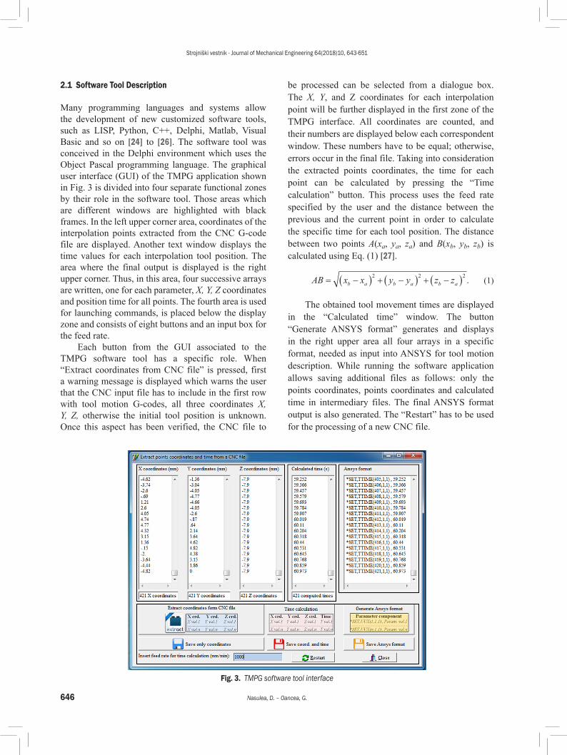
2.1 Software Tool Description
Many programming languages and systems allow the development of new customized software tools, such as LISP, Python, C++, Delphi, Matlab, Visual Basic and so on [24] to [26]. The software tool was conceived in the Delphi environment which uses the Object Pascal programming language. The graphical user interface (GUI) of the TMPG application shown in Fig. 3 is divided into four separate functional zones by their role in the software tool. Those areas which are different windows are highlighted with black frames. In the left upper corner area, coordinates of the interpolation points extracted from the CNC G-code file are displayed. Another text window displays the time values for each interpolation tool position. The area where the final output is displayed is the right upper corner. Thus, in this area, four successive arrays are written, one for each parameter, X, Y, Z coordinates and position time for all points. The fourth area is used for launching commands, is placed below the display zone and consists of eight buttons and an input box for the feed rate.
Each button from the GUI associated to the TMPG software tool has a specific role. When “Extract coordinates from CNC file” is pressed, first a warning message is displayed which warns the user that the CNC input file has to include in the first row with tool motion G-codes, all three coordinates X, Y, Z, otherwise the initial tool position is unknown. Once this aspect has been verified, the CNC file to
be processed can be selected from a dialogue box. The X, Y, and Z coordinates for each interpolation point will be further displayed in the first zone of the TMPG interface. All coordinates are counted, and their numbers are displayed below each correspondent window. These numbers have to be equal; otherwise, errors occur in the final file. Taking into consideration the extracted points coordinates, the time for each point can be calculated by pressing the “Time calculation” button. This process uses the feed rate specified by the user and the distance between the previous and the current point in order to calculate the specific time for each tool position. The distance between two points A(xa, ya, za) and B(xb, yb, zb) is calculated using Eq. (1) [27].
AB x x y y z zb a b a b a= −( ) + −( ) + −( )2 2 2
. (1)
The obtained tool movement times are displayed in the “Calculated time” window. The button “Generate ANSYS format” generates and displays in the right upper area all four arrays in a specific format, needed as input into ANSYS for tool motion description. While running the software application allows saving additional files as follows: only the points coordinates, points coordinates and calculated time in intermediary files. The final ANSYS format output is also generated. The “Restart” has to be used for the processing of a new CNC file.
Fig. 3. TMPG software tool interface

Strojniški vestnik - Journal of Mechanical Engineering 64(2018)10, 643-651
647Integrating a New Software Tool Used for Tool Path Generation in the Numerical Simulation of Incremental Forming Processes
2.2 TMPG Input and Output Files
Considering that TMPG aims to generate the tool movements for an incremental forming process in a format that can be specified in ANSYS software, the software tool needs an input file. This input is a CNC G-code generated by a CAM software system. Fig. 4 presents a sequence of a G-code structure for a CNC file generated by using CATIA “Advanced Machining” workbench.
In this example, the file extension is “NCCode”. There can be linear or circular interpolations. For circular interpolations, the trajectory is also described as a sum of very small linear movements, which at the end describe a circular motion. Thus, first, the CNC file has to be generated by using a CAM software system, to ensure an input data for the TMPG software tool.
The CNC input file will be processed by using the developed TMPG software tool, the final result being the obtained ANSYS output file. The data that can be accepted by ANSYS are a set of lines or arrays in a specific format for each position point parameter X, Y and Z and also for the tool position time. Fig. 5 shows the text format for each parameter that will be specified as input in the ANSYS software system.
Fig. 4. CNC G-code structure
a) b)
c) d) Fig. 5. Text format for ANSYS input; a) for the X-axis;
b) for the Y-axis; c) for the Z-axis; d) for the tool position time
The symbols used in these files have the following meanings:• UUX, UUY, UUZ and TTime are the names for
each set of lines or arrays;• n is the number of interpolation points in the
CNC file;• X1...Xn, Y1...Yn, Z1...Zn, T1...Tn - are the values
for the X, Y, Z coordinates and time for each interpolation point.In ANSYS parametric design language (APDL)
there are two methods by that the available commands in ANSYS software can be used. The first method is to use the GUI to access the commands, and the second method is to use the “command prompt” to run the specific commands by writing the codes that are the abbreviation of these commands [28]. For specifying the generated parameters for tool movements, the proper way is to use the “command prompt” to input the generated data by using the developed TMPG software tool. Thus, the TMPG software tool generates four arrays, one for each parameter X, Y, Z and Time. All these arrays are automatically written by the developed software tool in a single text file which can be introduced as input for tool movements, or simply copy the text file to ANSYS “command prompt”.
3 INTEGRATING AND VALIDATING THE NEW SOFTWARE TOOL IN AN ISF PROCESS -
A CASE STUDY
The objective of the case study is to integrate the new software tool into an ISF process, to verify if various dimensional configurations of a frustum of the cone can be manufactured without fracture and, at the same time, to predict the values of the developed forces. These force values will be used to determine whether a Victor Vcentre-55 CNC milling machine can be used for experimental research in incremental sheet forming. In incremental forming, the forming tool applies force on the sheet blank, thus producing a local plastic deformation of the contact surface between tool and sheet. The three components of the force are the radial force Fx, the tangential force Fy and the axial force Fz that typically is the largest [2] and [29]. Further determined in this case study whether this milling machine is capable of applying enough force in X, Y and Z directions, for an incremental deformation of the experimental sheet metal parts manufactured from DC05 deep drawing steel of 1mm thickness. To check if the part configurations can be manufactured and to estimate the values of the forces, a numerical simulation in ANSYS/LS-DYNA FEM software was performed, using the TMPG software tool to obtain,

Strojniški vestnik - Journal of Mechanical Engineering 64(2018)10, 643-651
648 Nasulea, D. – Oancea, G.
in a short time, the time tool movements and points coordinates. For a better overview of the process behaviour and the force variation, six numerical simulations were performed for different geometrical configurations of the experimental part presented in Fig. 6.
Fig. 6. Experimental frustum of a cone
Different parts variants with different wall angles ϕ (40°, 50° and 60°) and height values (35 mm, 45 mm and 50 mm) are analysed, manufactured from deep drawing sheet metal blank DC05 of 1 mm thickness. For each variant, two step depth Δz were used: 0.5 mm and 1 mm. The FEM models for simulation were prepared in ANSYS APDL and solved using an LS-DYNA explicit solver [30] and [31]. Fig. 7 presents the main steps for the implementation of FEM simulation in the incremental forming process. The 3D model of the part was designed in CATIA V5 CAD workbench, and then the tool trajectories were generated also in CATIA V5 Advanced machining workbench, from where the CNC file was obtained. Then, the CNC file was processed by using the developed TMPG software tool to obtain the needed ANSYS file. Thus in a few minutes, the application generated all four arrays with a minimum effort, which serve as input for ANSYS to describe the tool motion. Furthermore, in ANSYS, the materials were defined, the boundary conditions were applied, and an output K type file “Ansys_output.k” was obtained. This K file serves as input for the LS-DYNA explicit solver that will run and solve the simulation [30] and [31]. As an example of the obtained final result, Fig. 8 presents the plots for the frustum of a cone with a wall angle ϕ = 60° and H = 50 mm formed by using a step depth Δz = 1 mm.
The results for all the six studied parts were summarized in Table 1 that features the maximum values for the axial and radial forces. Because the frustum of a cone is an axis-symmetric part, the maximum force in the X direction is equal to the maximum force value in the Y direction. For this reason, the radial force is measured only in one direction, in this case in the X direction. Only the largest values of the forces from all six simulations results are necessary to check if the selected CNC
Table 1. Axial and radial forces for each part configuration
Part configurationMaximum axial force
[N]
Maximum radial force
[N]
ϕ = 40°, H = 35 mm, Δz = 0.5 mm 2062.2 711.17
ϕ = 40°, H = 35 mm, Δz = 1 mm 2189.3 786.44
ϕ = 50°, H = 45 mm, Δz = 0.5 mm 2516.0 1104.8
ϕ = 50°, H = 45 mm, Δz = 1 mm 2760.7 1196.7
ϕ = 60°, H = 50 mm, Δz = 0.5 mm 2650.2 1443.2
ϕ = 60°, H = 50 mm, Δz = 1 mm 2931.9 1624.1
Fig. 7. Main steps for the implementation of FEM simulation
a)
b)
c)
Fig. 8. Obtained results for ϕ = 60°, H = 50 mm and Δz = 1 mm part configuration; a) resulted FEM model; b) axial force plot;
c) radial force plot
Strojniški vestnik - Journal of Mechanical Engineering 64(2018)10, 643-651
649Integrating a New Software Tool Used for Tool Path Generation in the Numerical Simulation of Incremental Forming Processes
a)
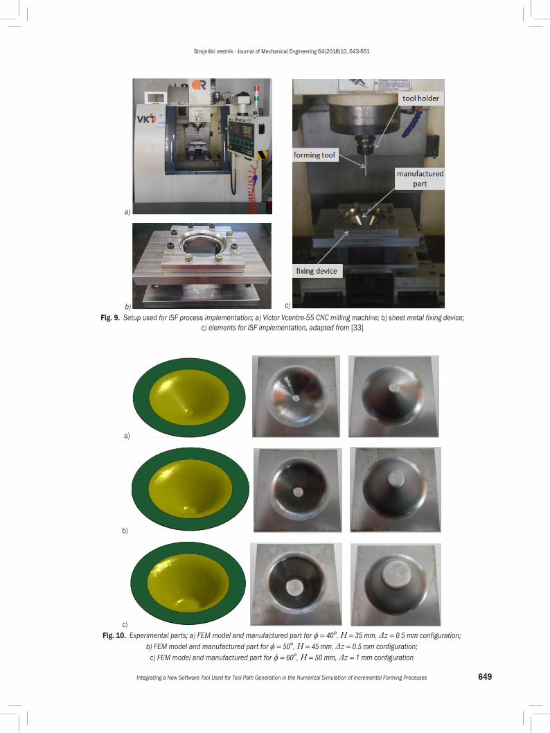
b) c) Fig. 9. Setup used for ISF process implementation; a) Victor Vcentre-55 CNC milling machine; b) sheet metal fixing device;
c) elements for ISF implementation, adapted from [33]
a)
b)
c) Fig. 10. Experimental parts; a) FEM model and manufactured part for ϕ = 40°, H = 35 mm, Δz = 0.5 mm configuration;
b) FEM model and manufactured part for ϕ = 50°, H = 45 mm, Δz = 0.5 mm configuration; c) FEM model and manufactured part for ϕ = 60°, H = 50 mm, Δz = 1 mm configuration

Strojniški vestnik - Journal of Mechanical Engineering 64(2018)10, 643-651
650 Nasulea, D. – Oancea, G.
milling machine can be used for the ISF process. From Table 1, it follows that in order to be deformed the part configuration with wall angle 60̊, height 50 mm and step depth 1 mm requires the largest forces both axial and radial. These values are 2931.9 N for the axial force and 1624.1 N for the radial force.
The CNC milling machine Victor Vcentre-55 is capable of developing, based on its X, Y, Z axis ball screws transmission, over 22000 N force along the X and Y axes and over 33500 N force along the Z axis [32]. To avoid damaging the CNC machine mechanisms over time, the manufacturer recommends that in ISF processes, the developed forces do not exceed half of the above-specified values. In this case, the maximum radial and axial forces resulted from FEM simulation are smaller than the recommendation of the milling machine manufacturer. Fig. 9 shows the CNC milling machine, the sheet metal blank fixing device and a short overview of the setup used to implement the ISF process [33].
With regard to parts forming, the numerical simulation prediction that all the part configurations can be manufactured without fracture was validated by machining the parts. Fig. 10 presents both the numerically simulated and the manufactured parts for three configurations using a step depth of 0.5 mm.
The conclusion of the case study is that the new software tool is successfully integrated into an ISF process, and the selected part configurations were manufactured without fracture in accordance with the numerical simulation prediction. The considered CNC milling machine can be used safely for machining the presented parts within future experimental research in the field of incremental sheet metal forming.
4 CONCLUSIONS
In the numerical simulation of incremental forming processes, the preparation of the FEM models is a time-consuming stage because the FEM software systems do not allow introducing the CAM programmed tool paths directly as inputs. The paper presents an original software tool named TMPG which ensures an easy way to obtain the tool path points coordinates and their position time that have to be introduced into ANSYS software for the description of the tool motion. This software tool allows any user with no specialized software knowledge, the quick processing of the tool path CNC file, finalized with the generation of a text file that contains the information needed to describe the same tool trajectories in ANSYS software. The TMPG utility was proved in a case study of simulating an
ISF process of a different frustum of cone geometrical configurations, highlighting the importance of the software tool in the FEM model preparation process. The special utility of the new software tool developed by the authors consists in the fact that the ANSYS file for tool movement description is obtained in a very short time. By using the TMPG application, the FEM model preparation time is reduced substantially, thus avoiding the manual processing or other complex software tools that require additional knowledge and special skills.
5 REFERENCES
[1] Mulay, A., Ben S., Ismail S., Kocanda A. (2017). Experimental investigations into the effects of SPIF forming conditions on surface roughness and formability by design of experiments. Journal of the Brazilian Society of Mechanical Sciences and Engineering, vol. 39, no. 10, p. 3997-4010, DOI:10.1007/s40430-016-0703-7.
[2] Nasulea, D., Oancea, G. (2017). Incremental deformation: A literature review. 8th International Conference on Manufacturing Science and Education, p. 03017, DOI:10.1051/matecconf/201712103017.
[3] Jeswiet, J., Geiger, M., Engel, U., Kleiner, M., Schikorra, M., Duflou, J., Neugebauer, R., Bariani, P., Bruschi, S. (2008). Metal forming progress since 2000. CIRP Journal of Manufacturing Science and Technology, vol. 1, no. 1, p. 2-17, DOI:10.1016/j.cirpj.2008.06.005.
[4] Sharma, V., Gohil, A., Modi, B. (2017). Experimental investigation of single point incremental forming of aluminum sheet in groove test. Applied Mechanics and Materials, vol. 867, p. 177-183, DOI:10.4028/www.scientific.net/AMM.867.177.
[5] Felippa, C. (2015) Introduction to Finite Element Methods, Appendix O index: The Origins of the Finite Element Method. from: http://www.colorado.edu/engineering/CAS/courses.d/IFEM.d/Home.html, accessed on 2018-26-04.
[6] Pepelnjak, T., Milutinović, M., Plančak, M., Vilotić, D., Randjelović, S., Movrin D. (2016). The influence of extrusion ratio on contact stresses and die elastic deformations in the case of cold backward extrusion. Strojniški vestnik - Journal of Mechanical Engineering, vol. 62, no. 1, p. 41-50, DOI:10.5545/sv-jme.2015.3051.
[7] Deng, W.J., Zhang, J.Y., Liu, L.W., He, D., Xia, W. (2017). Simulation analysis of a new chips recycling process termed forming extrusion cutting. International Journal of Simulation Modelling, vol. 16, no. 4, p. 694-706, DOI:10.2507/IJSIMM16(4)CO16.
[8] Trzepiecinski, T., Lemu, H.G., Fejkiel, R. (2017). Numerical simulation of effect of friction directionality on forming of anisotropic sheets. International Journal of Simulation Modelling, vol. 16, no. 4, p. 590-602, DOI:10.2507/IJSIMM16(4)3.392.
[9] Blaga, A., Oleksik, V. (2013). A study of the influence of the forming strategy on main strains, thickness reduction and forces in single point incremental forming process. Advances

Strojniški vestnik - Journal of Mechanical Engineering 64(2018)10, 643-651
651Integrating a New Software Tool Used for Tool Path Generation in the Numerical Simulation of Incremental Forming Processes
in Materials Science and Engineering, art. id. 382635, DOI:10.1155/2013/382635.
[10] Gatea, S., Ou, H., McCartney, G. (2016). Review on the influence of process parameters in incremental sheet forming. The International Journal of Advanced Manufacturing Technology, vol. 87, no. 1-4, p. 479-499, DOI:10.1007/s00170-016-8426-6.
[11] Fu, Z., Mo, J., Han, F., Gong, P. (2013). Tool path correction algorithm for single-point incremental forming of sheet metal. The International Journal of Advanced Manufacturing Technology, vol. 64, no. 9-12, p. 1239-1248, DOI:10.1007/s00170-012-4082-7.
[12] Lemeš, S., Zaimović-Uzunović, N. (2008). Using buckling analysis to predict wrinkling in incremental sheet metal forming. Strojniški vestnik - Journal of Mechanical Engineering, vol. 54, no. 2, p. 115-121.
[13] Liu, N., Yang, H., Li, H., Yan, S. (2016). Plastic wrinkling prediction in thin-walled part forming process: A review. Chinese Journal of Aeronautics, vol. 29, no. 1, p. 1-14, DOI:10.1016/j.cja.2015.09.004.
[14] Nimbalkar, D.H., Nandedkar, V.M. (2013). Review of incremental forming of sheet metal components. International Journal of Engineering Research and Application, vol. 3, no. 5, p. 39-51.
[15] Robert, C., Dal Santo, P., Delamézière, A., Potiron, A., Batoz, JL. (2008). On some computational aspects for incremental sheet metal forming simulations. International Journal of Material Forming, vol. 1, p. 1195-1198, DOI:10.1007/s12289-008-0155-4.
[16] Senthil, R., Gnanavelbabu, A. (2014). Numerical analysis on formability of AZ61A magnesium alloy by incremental forming. Procedia Engineering, vol. 97, p. 1975-1982, DOI:10.1016/j.proeng.2014.12.352.
[17] Benedetti, M., Fontanari, V., Monelli, B., Tassan, M. (2015). Single-point incremental forming of sheet metals: Experimental study and numerical simulation. Proceedings of the Institution of Mechanical Engineers, Part B: Journal of Engineering Manufacture, vol. 231, no. 2, p. 301-312, DOI:10.1177/0954405415612351.
[18] Naranjo, J., Miguel, V., Martínez-Martínez, A., Gómez-López, L.M., Manjabacas, M.C., Coello, J. (2015). Analysis and simulation of single point incremental forming by ANSYS. Procedia Engineering, vol. 132, p. 1104-1111, DOI:10.1016/j.proeng.2015.12.602.
[19] Ben Ayed, L., Robert, C., Delamézière, A., Nouari, M., Batoz, J.L. (2014). Simplified numerical approach for incremental sheet metal forming process. Engineering Structures, vol. 62-63, p. 75-86, DOI:10.1016/j.engstruct.2014.01.033.
[20] Sebastiani, G., Brosius, A., Tekkaya, A.E., Homberg, W., Kleiner, M. (2007). Decoupled simulation method for incremental sheet metal forming. AIP Conference Proceedings, vol. 908, p. 1501-1506, DOI:10.1063/1.2741021.
[21] Bambach, M. (2016). Fast simulation of incremental sheet metal forming by adaptive remeshing and subcycling. International Journal of Material Forming, vol. 9, no. 3, p. 353-360, DOI:10.1007/s12289-014-1204-9.
[22] Zhang, M.H., Lu, B., Chen, J., Long, H., Ou, H. (2015). Selective element fission approach for fast FEM simulation of incremental sheet forming based on dual-mesh system. The International Journal of Advanced Manufacturing Technology, vol. 78, no. 5-8, p. 1147-1160, DOI:10.1007/s00170-014-6723-5.
[23] Salah, B.M.E., Hrairi, M. (2011). Process simulation and quality evaluation of incremental sheet forming. IIUM Engineering Journal, vol. 12, no. 3, p. 185-196.
[24] Suresh, K., Khan, A., Regalla, S.P. (2013). Tool path definition for numerical simulation of single point incremental forming. Procedia Engineering, vol. 64, p. 536-545, DOI:10.1016/j.proeng.2013.09.128.
[25] Gusel, L., Rudolf, R., Brezocnik, M. (2015). Genetic based approach to predicting the elongation of drawn alloy. International Journal of Simulation Modelling, vol. 14, no. 1, p. 39-47, DOI:10.2507/IJSIMM14(1)4.277.
[26] Aguado, S., Velazquez, J., Samper, D., Santolaria, J. (2016). Modelling of computer-assisted machine tool volumetric verification process. International Journal of Simulation Modelling, vol. 15, no. 3, p. 497-510, DOI:10.2507/IJSIMM15(3)9.353.
[27] Distance formula – MATHEMATICS (2018). from https://www.britannica.com/science/distance-formula, accessed on 2018-12-06.
[28] ANSYS Documentation (2018). from http://www.ansys.stuba.sk/html/elem_55/chapter1/ES1-1.htm, accessed on 2018-26-04.
[29] Behera, A. K., De Sousa, R.A., Ingarao, G., Oleksik, V. (2017). Single point incremental forming: An assessment of the progress and technology trends from 2005 to 2015. Journal of Manufacturing Processes, vol. 27, p. 37-62, DOI:10.1016/j.jmapro.2017.03.014.
[30] Oleksik, V. (2016). Numerical study about the influence of wall angle about main strains, thickness reduction and forces on single point incremental forming process. ACTA Universitatis Cibiniensis - Technical Series, vol. 68, p. 1-6, DOI:10.1515/aucts-2016-0001.
[31] Oleksik, V. (2005). Theoretical and Experimental Research on Incremental Forming of Indigenous Metal Sheets, PhD thesis. Lucian Blaga University of Sibiu, Sibiu. (in Romanian)
[32] Balls screws - technical information (2018) from http://pdf.directindustry.com/pdf/hiwin/ballscrews/14370-67561.html, accessed on 2018-26-04.
[33] Nasulea, D., Oancea, G. Design and manufacturing of a fixing device for incremental sheet forming process. 22nd International Conference on Innovative Manufacturing Engineering and Energy, vol. 178, art. no. 2004, DOI:10.1051/matecconf/201817802004.