integrated submillimeter and terahertz receivers with superconducting local oscillator
DESCRIPTION
Integrated Submillimeter and Terahertz Receivers with Superconducting Local Oscillator. V.P. Koshelets , S.V. Shitov, P.N. Dmitriev, A.B. Ermakov, L.V.Filippenko, O.V. Koryukin, A.S. Sobolev, M.Yu. Torgashin Institute of Radio Engineering and Electronics (IREE), Moscow, Russia - PowerPoint PPT PresentationTRANSCRIPT
March 24, 2004 Björkliden, Sweden
Integrated Submillimeter and Integrated Submillimeter and Terahertz Receivers with Terahertz Receivers with
Superconducting Local OscillatorSuperconducting Local Oscillator
V.P. Koshelets, S.V. Shitov, P.N. Dmitriev, A.B. Ermakov, L.V.Filippenko, O.V. Koryukin, A.S. Sobolev,
M.Yu. TorgashinInstitute of Radio Engineering and Electronics (IREE), Moscow, Russia
T. de Graauw, W. Luinge, R. Hoogeveen, P. Yagoubov National Institute for Space Research (SRON), the Netherlands

March 24, 2004 Björkliden, Sweden 2
Integrated Submillimeter and Integrated Submillimeter and Terahertz Receivers with Terahertz Receivers with
Superconducting Local OscillatorSuperconducting Local Oscillator
OutlineOutline
· Superconducting Integrated Receiver (SIR) – Introduction· SIR - State of Art· FFO Phase Locking; Phase Noise· SIR with Phase Locked FFO – First Implementation· TErahertz LImb Sounder (TELIS)· Optimization of the FFO for TELIS· 1 THz SIR - Prospects and Limitations· Conclusion
March 24, 2004 Björkliden, Sweden 3
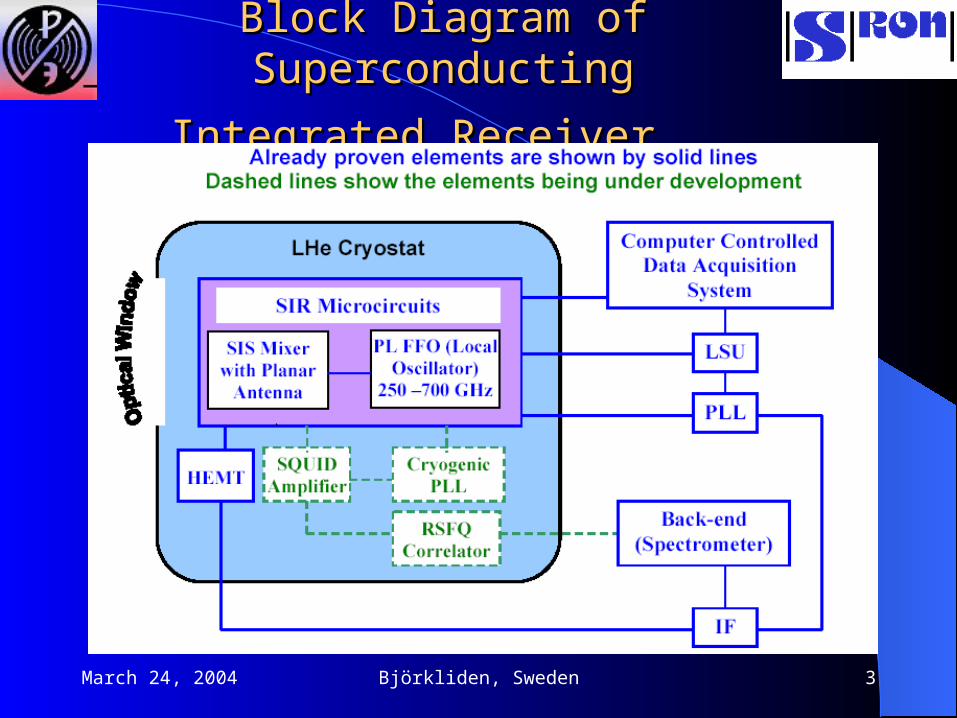
Block Diagram of Superconducting Block Diagram of Superconducting
Integrated ReceiverIntegrated Receiver

March 24, 2004 Björkliden, Sweden 4
Integrated Submm Wave ReceiverIntegrated Submm Wave Receiver Single chip SIS receivers with
superconducting FFO has been studied at frequencies from 100 to 700 GHz
A DSB receiver noise temperature as low as 90 K has been achieved at 500 GHz
9-pixel Imaging Array Receiver has been successfully tested
Phase Locking (PLL) up to 700 GHz
POSSIBLE APPLICATIONS Airborne Receiver for Atmospheric
Research and Environmental Monitoring; Radio Astronomy
Large Imaging Array Receiver Laboratory General Purpose MM &
subMM Wave Receiver

March 24, 2004 Björkliden, Sweden 5
Integrated Receiver MicrocircuitsIntegrated Receiver Microcircuits
Antenna tuner
Antenna tuner
SIS junction1 μm x1 μm
SIS junction1 μm x1 μm
Antenna - 1Antenna - 1
Antenna - 2Antenna - 2
LO injector(1 μm wide /4microstrip line)
LO injector(1 μm wide /4microstrip line)
Antenna tunerAntenna tuner
LO feeder(4 μm wide
microstrip line)
LO feeder(4 μm wide
microstrip line)
DC bias/IF output & control line for Josephson
noise suppression
DC bias/IF output & control line for Josephson
noise suppression
20 m

March 24, 2004 Björkliden, Sweden 6
Replaceable Module of the 500 GHz
Imaging Array Superconducting Integrated Receiver

March 24, 2004 Björkliden, Sweden 7
Nine-pixel
Imaging Array
Receiver Block.

March 24, 2004 Björkliden, Sweden 8
Antenna Beam Pattern of the SIRAntenna Beam Pattern of the SIR
March 24, 2004 Björkliden, Sweden 9
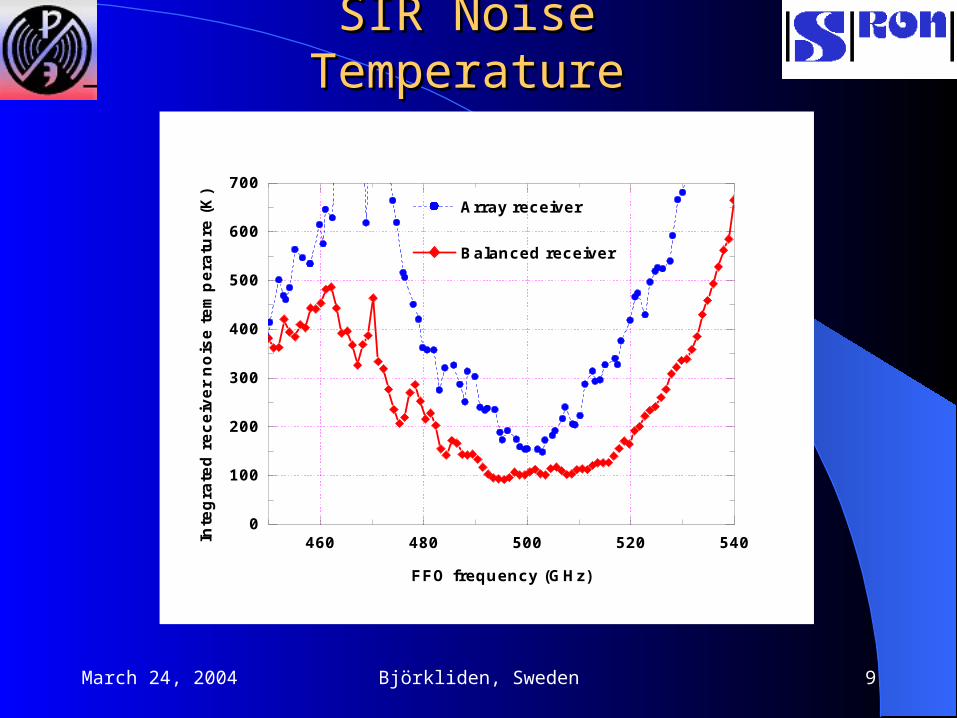
SIR Noise TemperatureSIR Noise Temperature
460 480 500 520 5400
100
200
300
400
500
600
700 Array receiver
Balanced receiver
Inte
gra
ted
rec
eive
r n
ois
e te
mp
erat
ure
(K
)
FFO frequency (GHz)

March 24, 2004 Björkliden, Sweden 10
Flux Flow OscillatorFlux Flow Oscillator

March 24, 2004 Björkliden, Sweden 11
FFO + SIS; Frequency ControlFFO + SIS; Frequency Control
FFO frequency 265 GHz437 GHz570 GHz
670 GHz
March 24, 2004 Björkliden, Sweden 12
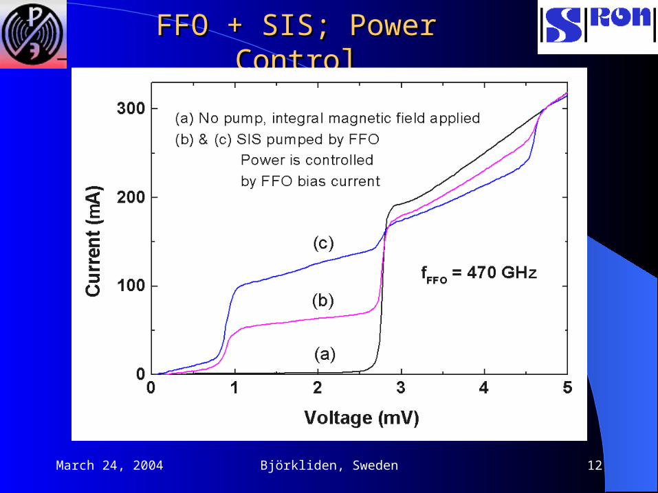
FFO + SIS; Power ControlFFO + SIS; Power Control
March 24, 2004 Björkliden, Sweden 13
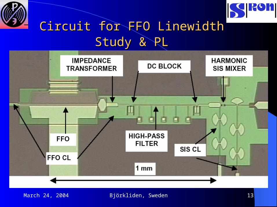
Circuit for FFO LinewidthCircuit for FFO Linewidth Study & PLStudy & PL
March 24, 2004 Björkliden, Sweden 14
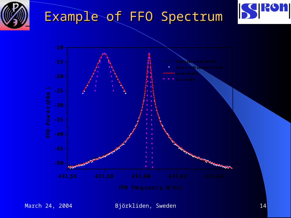
Example of FFO SpectrumExample of FFO Spectrum
431,56 431,58 431,60 431,62 431,64
-50
-45
-40
-35
-30
-25
-20
-15
-10
Experimental Data Symmeterizated Data Lorentzian Gaussian
FF
O P
ow
er (d
Bm)
FFO Frequency (GHz)
March 24, 2004 Björkliden, Sweden 15
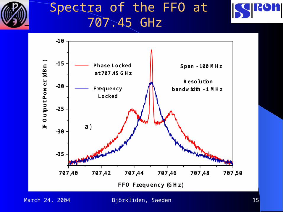
Spectra of the FFO at 707.45 GHz
707,40 707,42 707,44 707,46 707,48 707,50
-35
-30
-25
-20
-15
-10
a)
Span - 100 MHz
Resolution bandwidth - 1 MHz
IF O
utp
ut
Po
wer
(d
Bm
)
FFO Frequency (GHz)
Phase Locked at 707.45 GHz
Frequency Locked

March 24, 2004 Björkliden, Sweden 16
Down-convertedDown-converted spectrum of the spectrum of the FFO phase locked at 707.5 GHzFFO phase locked at 707.5 GHz
399,99995 400,00000 400,00005
-90
-80
-70
-60
-50
-40
-30
-20
-10
b)
Span - 100 Hz
Resolution bandwidth - 1 Hz
IF
Ou
tpu
t P
ow
er (
dB
m)
Down-converted FFO Frequency (MHz)
FFO Phase Locked at 707.45 GHz
March 24, 2004 Björkliden, Sweden 17
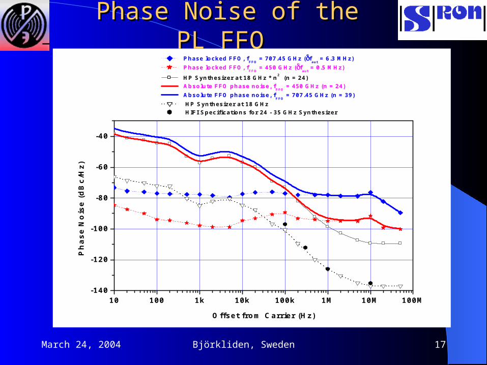
Phase Noise of the PL FFO Phase Noise of the PL FFO
10 100 1k 10k 100k 1M 10M 100M-140
-120
-100
-80
-60
-40
Phase locked FFO, fFFO
= 707.45 GHz (faut
= 6.3 MHz) Phase locked FFO, f
FFO = 450 GHz (f
aut = 0.5 MHz)
HP Synthesizer at 18 GHz * n2 (n = 24) Absolute FFO phase noise, f
FFO = 450 GHz (n = 24)
Absolute FFO phase noise, fFFO
= 707.45 GHz (n = 39) HP Synthesizer at 18 GHz HIFI Specifications for 24 - 35 GHz Synthesizer
Ph
as
e N
ois
e (
dB
c/H
z)
Offset from Carrier (Hz)

March 24, 2004 Björkliden, Sweden 18
Microcircuit of the superconducting
integrated receiver with phase-locked
Josephson oscillator.
The chip size is 4 mm by 4 mm.
1
2
3
4
5
9 10 11 12 13 14
15
16
17
18
19
6 7 8
20
21 23 24 2522
26 27
28

March 24, 2004 Björkliden, Sweden 19
Spectral Resolution of the SIR Spectral Resolution of the SIR With Phase-locked FFOWith Phase-locked FFO
362,6540 362,6542 362,6544 362,6546 362,6548 362,6550
-40
-30
-20
-10
0
IF O
utp
ut
Po
wer
(d
Bm
)
FFO Frequency (GHz)
Span - 1 MHz
Resolution bandwidth - 10 kHz

March 24, 2004 Björkliden, Sweden 20
Spectral line of SOSpectral line of SO22 at at 326.867 GHz326.867 GHz detected by SIR with phased-locked FFO detected by SIR with phased-locked FFO
and processed by AOSand processed by AOS
March 24, 2004 Björkliden, Sweden 21
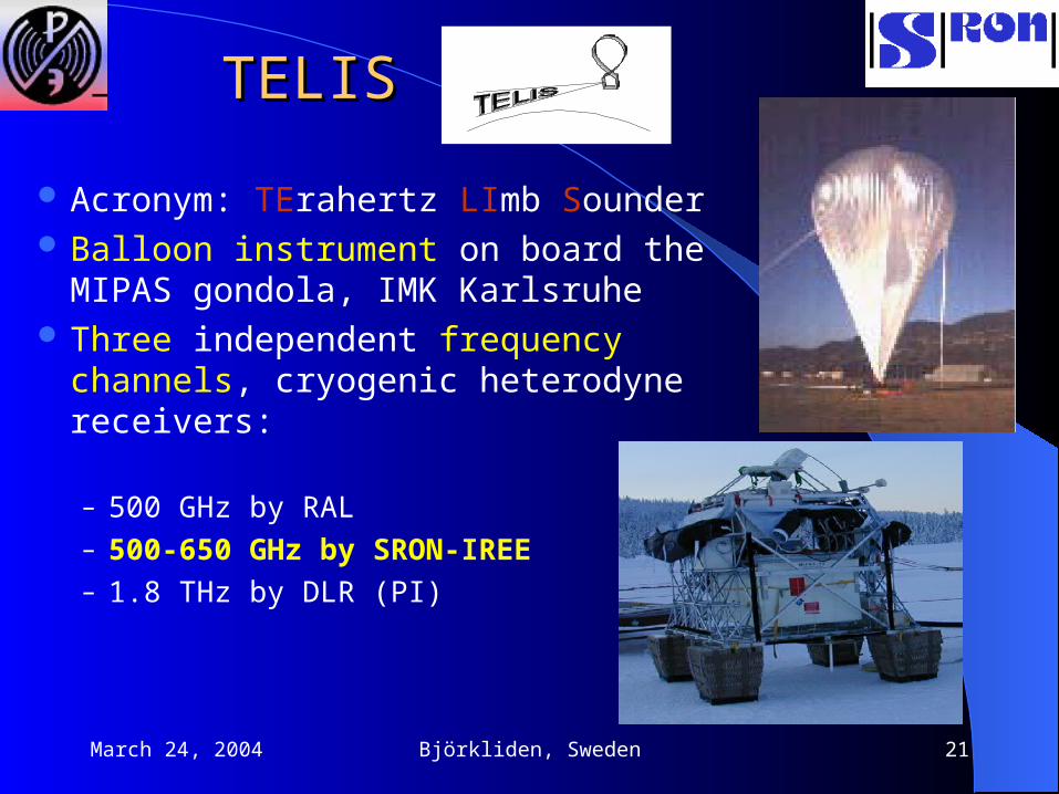
TELISTELIS
Acronym: TErahertz LImb Sounder Balloon instrument on board the MIPAS
gondola, IMK Karlsruhe Three independent frequency channels,
cryogenic heterodyne receivers:
– 500 GHz by RAL– 500-650 GHz by SRON-IREE– 1.8 THz by DLR (PI)

March 24, 2004 Björkliden, Sweden 22
TELIS ObjectivesTELIS Objectives
Measure many species (together with MIPAS-B), for atmospheric science
Serve as a test platform for new sensors
Serve as validation tool for future satellite missions

March 24, 2004 Björkliden, Sweden 23
Example of the Atmospheric Example of the Atmospheric SpectrumSpectrum

March 24, 2004 Björkliden, Sweden 24
TELIS-SIR Main ParametersTELIS-SIR Main Parameters
## Description Base line Goal1 Input frequency range, GHz 600 - 650 500-6502 Minimum noise temperature in the range (DSB), K 200 2503 Output IF range, GHz 4 - 8 4 - 84 Spectral resolution (width of the spectral channel), MHz 1 15 Contribution to the nearest spectral channel by phased
locked FFO (dynamic range of the spectrometer), dB-20 -20
6 Contribution to a spectral channel by phased locked FFO at 4-6 GHz offset from the carrier, K
20 20
7 LO frequency net (distance between nearest settings of the PL FFO frequency), MHz
< 300 < 300
8 Dissipated power at 4.2 K stage
(including IF amplifiers chain), mW
100 50
9 Operation temperature, K < 4.5 < 4.5
March 24, 2004 Björkliden, Sweden 25
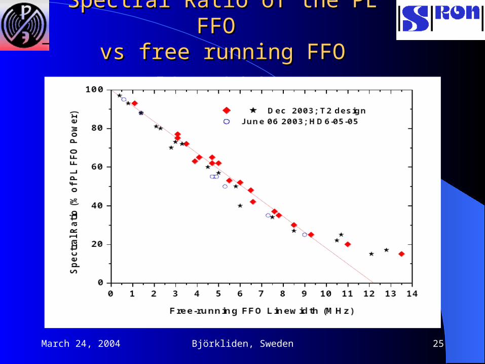
Spectral Ratio of the PL FFO Spectral Ratio of the PL FFO
vs free running FFO linewidthvs free running FFO linewidth

March 24, 2004 Björkliden, Sweden 26
FFO Linewidth: DependenceFFO Linewidth: Dependence on on Frequency and Current DensityFrequency and Current Density

March 24, 2004 Björkliden, Sweden 27
Flux Flow OscillatorFlux Flow Oscillator
RRddBB = = V/ V/ IIBB
RRddCLCL = = VVFFOFFO//IICLCL

March 24, 2004 Björkliden, Sweden 28
0,00 0,02 0,04 0,060,00
0,02
0,04
0,06
0,08
0,10
0,12
0,14
0,16
0,18
RdCl = 0.001 + 2.73*Rd Ib = 30 mA Ib = 27 mA Ib = 21 mA Ib = 15 mA
Rd
CL
(O
hm
)
Rd (Ohm)
RRddCLCL as a function of R as a function of Rdd

March 24, 2004 Björkliden, Sweden 29
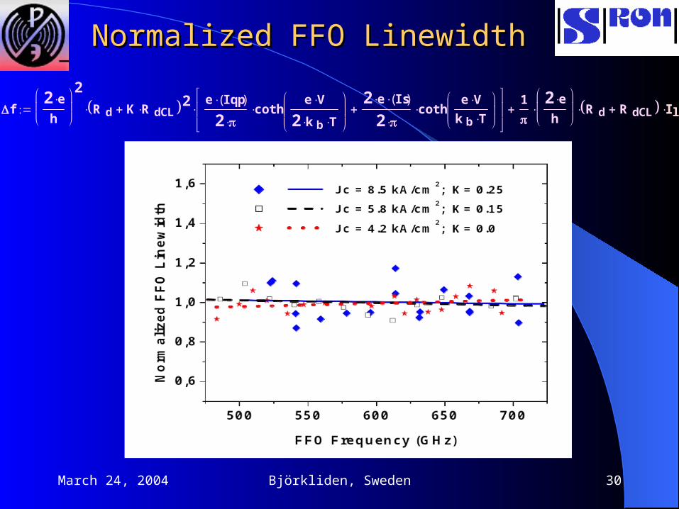
Normalized FFO LinewidthNormalized FFO Linewidth
f2 e
h
2
R d K R dCL 2e Iqp( )
2 coth
e V
2 k b T
2 e Is( )
2 coth
e Vk b T
1
2 e
h
R d R dCL I lf I lf
March 24, 2004 Björkliden, Sweden 30
Normalized FFO LinewidthNormalized FFO Linewidth
f2 e
h
2
R d K R dCL 2e Iqp( )
2 coth
e V
2 k b T
2 e Is( )
2 coth
e Vk b T
1
2 e
h
R d R dCL I lf I lf

March 24, 2004 Björkliden, Sweden 31
FFO Linewidth on (RFFO Linewidth on (Rdd + R + RddCLCL))

March 24, 2004 Björkliden, Sweden 32
FFO Linewidth (Design issue)FFO Linewidth (Design issue)
March 24, 2004 Björkliden, Sweden 33
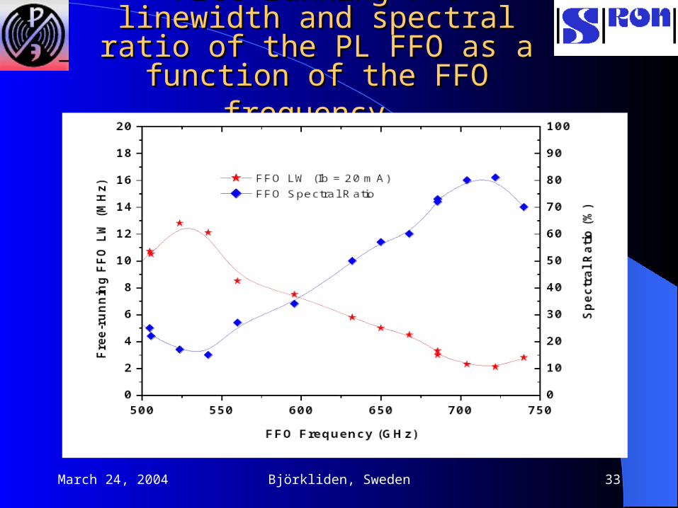
Free-running FFO linewidth and Free-running FFO linewidth and spectral ratio of the PL FFO as a spectral ratio of the PL FFO as a function of the FFO frequencyfunction of the FFO frequency
March 24, 2004 Björkliden, Sweden 34
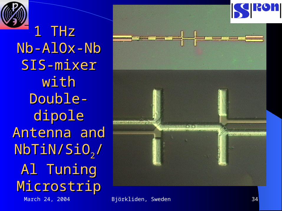
1 THz 1 THz Nb-AlOx-Nb Nb-AlOx-Nb
SIS-mixer with SIS-mixer with Double-dipole Double-dipole Antenna and Antenna and
NbTiN/SiONbTiN/SiO22/Al /Al
Tuning Tuning MicrostripMicrostrip
March 24, 2004 Björkliden, Sweden 35
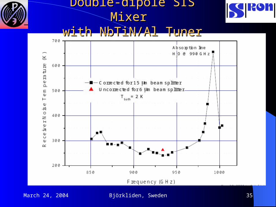
Double-dipole SIS Mixer Double-dipole SIS Mixer with NbTiN/Al Tunerwith NbTiN/Al Tuner

March 24, 2004 Björkliden, Sweden 36
Nb-AlN-Nb Junctions for THz SIR:Nb-AlN-Nb Junctions for THz SIR:Jc = 8 and 19 kA/cmJc = 8 and 19 kA/cm22
0,0 0,5 1,0 1,5 2,0 2,5 3,0 3,5 4,00,0
0,1
0,2
0,3
0,4
0,5
RnA = 24 m2
J = 8 kA/cm2
Rj/Rn = 20
Cur
rent
, mA
Voltage, mV
0,0 0,5 1,0 1,5 2,0 2,5 3,0 3,5 4,00,00
0,25
0,50
0,75
1,00
1,25
RnA = 10 m2
J = 19 kA/cm2
Rj/Rn = 16
Cur
rent
, mA
Voltage, mV

March 24, 2004 Björkliden, Sweden 37
Nb-AlN-Nb Junctions for THz SIR:Nb-AlN-Nb Junctions for THz SIR: Jc = 70 and 210 kA/cm Jc = 70 and 210 kA/cm22
0,0 0,5 1,0 1,5 2,0 2,5 3,0 3,5 4,00
2
4
6
8
10
RnA = 0.9 m2
J = 210 kA/cm2
Rj/Rn = 8
Cur
rent
, mA
Voltage, mV
0,0 0,5 1,0 1,5 2,0 2,5 3,0 3,5 4,00
1
2
3
4
RnA = 2.7 m2
J = 70 kA/cm2
Rj/Rn = 12
Cur
rent
, mA
Voltage, mV

March 24, 2004 Björkliden, Sweden 38
Submicron Nb-AlN-Nb junction:Submicron Nb-AlN-Nb junction:S = 0.03 S = 0.03 22; Jc = 21 kA/cm; Jc = 21 kA/cm22; Rj/Rn = 14; Rj/Rn = 14
EBL + CMPEBL + CMP

March 24, 2004 Björkliden, Sweden 39
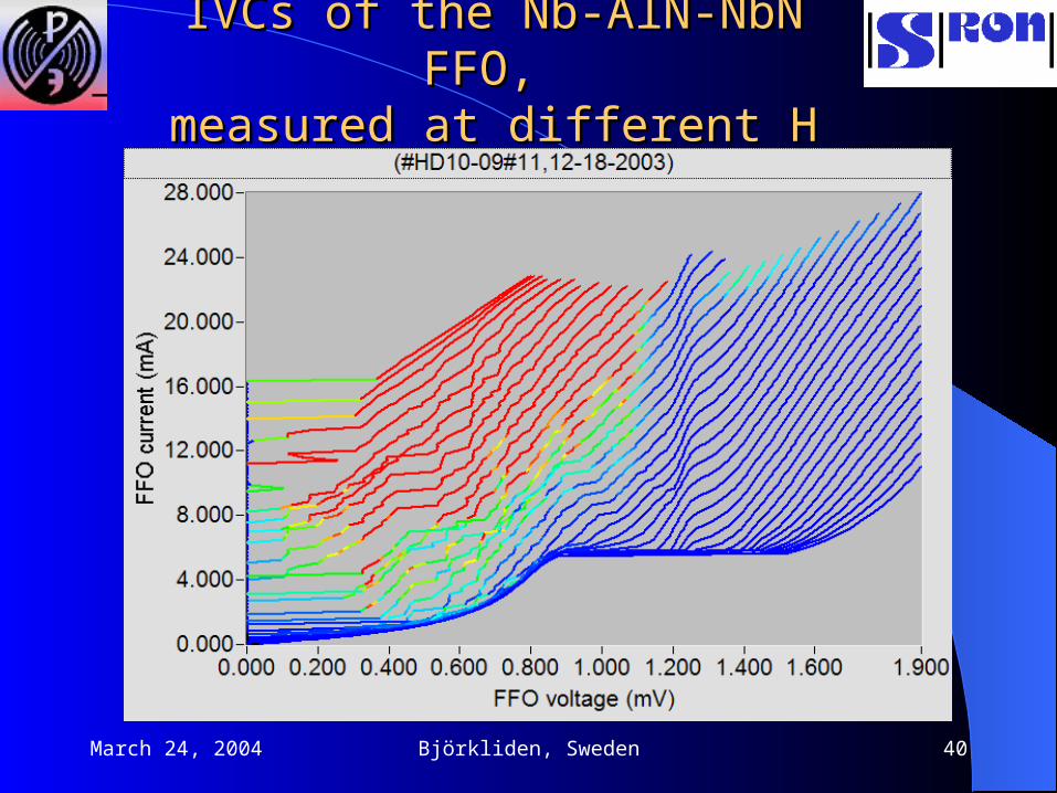
Nb-AlN-NbN JunctionsNb-AlN-NbN Junctions
0 1 2 3 4 5 60,00
0,05
0,10
0,15
Nb-AlN-NbN
RnS=100 W*m2
Vg = 3.55 mV Rj/Rn = 32
Cu
rren
t, m
A
Voltage, mV
March 24, 2004 Björkliden, Sweden 40
IVCs of the Nb-AlN-NbN FFO, IVCs of the Nb-AlN-NbN FFO, measured at different Hmeasured at different H

March 24, 2004 Björkliden, Sweden 41
Spectra of the Nb-AlN-NbN FFOSpectra of the Nb-AlN-NbN FFOat 597 GHz, at 597 GHz, f = 3.5 MHz; SR = 70%f = 3.5 MHz; SR = 70%

March 24, 2004 Björkliden, Sweden 42
THz SIR – Possible ImplementationsTHz SIR – Possible Implementations
FFO FFO MixerMixer NbN-MgO/AlN-NbN NbN-MgO/AlN-NbNVg up to 6 mV (1.5 THz) PLO 2 (1 W at 1 THz)
NbN-MgO/AlN-NbN Phonon Cooled NbN HEB PLO 0.1 W ( independent) TR 700 K at 1.5 THz
Stacked NbN-MgO-NbN Phonon Cooled NbN HEBfrequency up to 3 THz

March 24, 2004 Björkliden, Sweden 43
ConclusionConclusion
Optimization of of a Nb-AlOx-Nb Flux-Flow Oscillator design along with a development of the wide-band PLL system allow us to realize a FFO phase locking to a reference oscillator in the frequency range from 250 to 715 GHz. The measured absolute FFO phase noise is as low as –93 dBc/Hz at 1 MHz offset below the 450 GHz carrier. This fits the requirements for most practical applications.
The first implementation of a Superconducting Integrated Receiver (SIR) with phased locked FFO has been tested with a resolution better than 10 kHz. The phased locked SIR has been tested successfully as a laboratory spectrometer. This study provides an important input for future development of a balloon-based 500-650 GHz integrated receiver for the Terahertz Limb Sounder (TELIS) scheduled to fly in 2005-2006.
Receiver DSB noise temperature below 300 K has been achieved in the frequency range 850-970 GHz. Phase locking of a FFO with NbN electrodes has been demonstrated. Possible implementations of a SIR for operation at frequencies above 1 THz have been proposed.

March 24, 2004 Björkliden, Sweden 44
SRON-IREE and RAL ReceiversSRON-IREE and RAL Receivers
March 24, 2004 Björkliden, Sweden 45
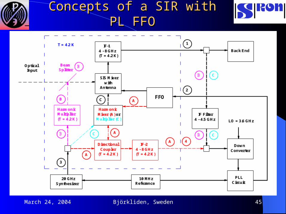
Concepts of a SIR with PL FFOConcepts of a SIR with PL FFO

March 24, 2004 Björkliden, Sweden 46
Ratio of PL and total FFO powerRatio of PL and total FFO power
1 10 1000,0
0,1
0,2
0,3
0,4
0,5
0,6
0,7
0,8
0,9
1,0
Sp
ectr
al R
atio
Free running 3 dB FFO linewidth (MHz)
PLL BW=5 MHz PLL BW=15 MHz PLL BW=50 MHz PLL BW=6 MHz - var PLL 3b - 11 Dec 02 PLL 3b - 24 Dec 02 PLL 3b - Short Cables PLL 6a - 01 Feb 03 FFO LW (MHz)
Eff. PLL BW (MHz)
March 24, 2004 Björkliden, Sweden 47
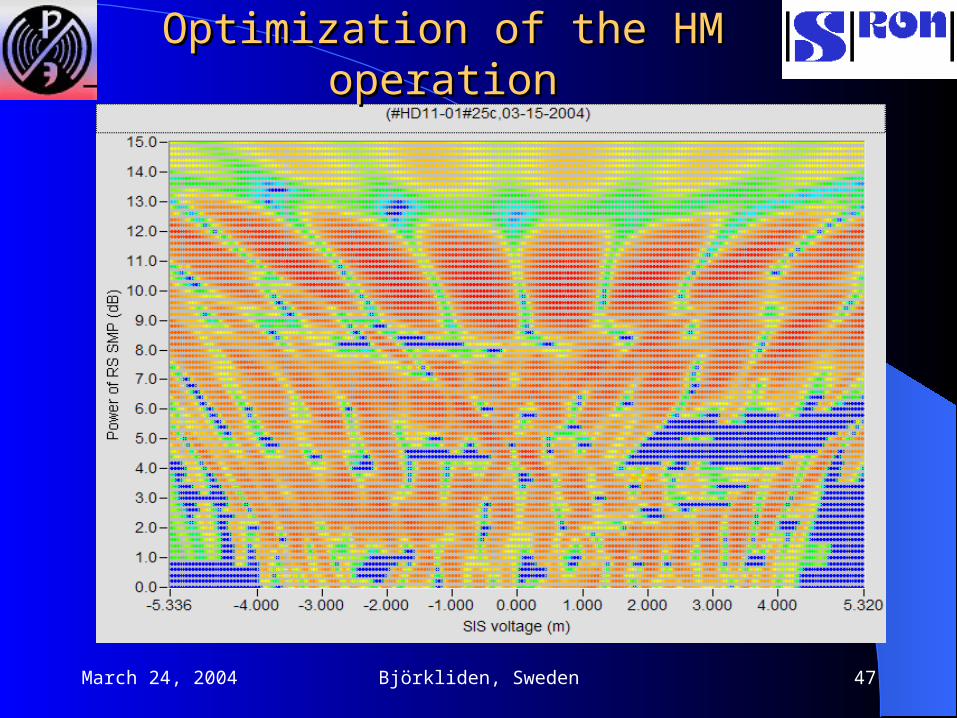
Optimization of the HM operationOptimization of the HM operation
March 24, 2004 Björkliden, Sweden 48
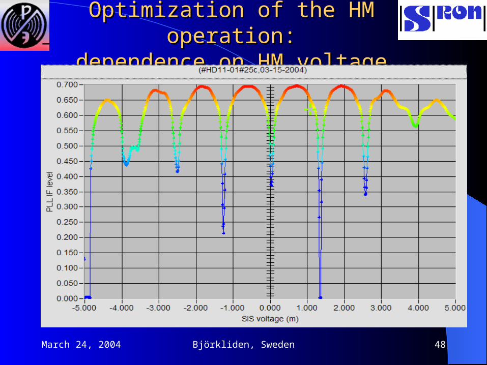
Optimization of the HM operation:Optimization of the HM operation:dependence on HM voltagedependence on HM voltage

March 24, 2004 Björkliden, Sweden 49
Optimization of the HM operation:Optimization of the HM operation:dependence on synthesizer power dependence on synthesizer power
March 24, 2004 Björkliden, Sweden 50
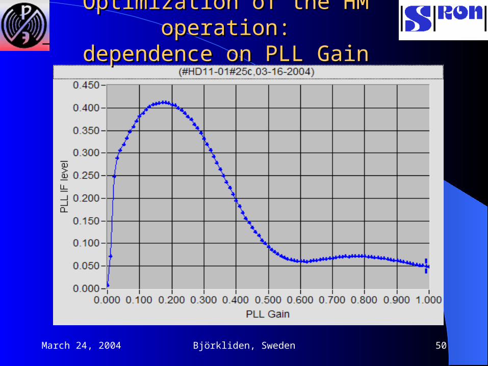
Optimization of the HM operation:Optimization of the HM operation:dependence on PLL Gaindependence on PLL Gain