integrated amplifier€¦ · sound quality is not adversely affected. 0bi-amp mode complete bi-amp...
TRANSCRIPT

.
Model PM-10 Owner’s Manual
Integrated Amplifier
Printing : Color : Full Color

ContentsAccessories .................................................................................... 2About the remote control .............................................................. 2
Inserting the batteries ................................................................... 2Operating range of the remote control unit .................................... 2
Features .......................................................................................... 3High quality sound ........................................................................ 3High performance ......................................................................... 3
Part names and functions ............................................................. 4Front panel ................................................................................... 4Rear panel .................................................................................... 5Remote control unit ....................................................................... 6
Connections ........................................................... 8Connecting speakers .................................................................... 8
Speaker connection ...................................................................... 9Bi-wiring connection ..................................................................... 9
Connecting a playback device ................................................... 10About balanced connectors ........................................................ 10
Connecting a recording device .................................................. 10F.C.B.S. connection ..................................................................... 11
Preparation for F.C.B.S. connection ........................................... 11Stereo complete bi-amp connection ........................................... 12Connection for 5.1 Multi-channel Playback ................................. 14
Connecting a pre-amplifier ......................................................... 15Connecting devices with remote control connectors .............. 16
Performing operations by RC on this unit without visual contact.................................................................................................... 16Remotely connecting Marantz audio devices ............................. 16
Connecting the power cord ........................................................ 16
Playback ............................................................... 17Turning the power on .................................................................. 17Selecting the input source .......................................................... 17Adjusting the volume .................................................................. 17Turning off the sound temporarily (Muting) ................................. 18Adjusting the left and right channel balance ............................... 18Having the display and the illumination lamp off ......................... 18Having the illumination lamp always off ...................................... 18Playing CDs ................................................................................ 19Recording ................................................................................... 19
Settings ................................................................ 20Menu map ..................................................................................... 20
Menu operation ........................................................................... 20PUREST ........................................................................................ 21PHONO .......................................................................................... 21AUTO STBY (Auto Standby) ....................................................... 21
Tips ....................................................................... 22Tips ............................................................................................. 23Troubleshooting .......................................................................... 24Error messages .......................................................................... 26
Appendix .............................................................. 27Explanation of terms ................................................................... 27Specifications .............................................................................. 28Index ............................................................................................. 30
1
Printing : Color : Black

Thank you for purchasing this Marantz product.To ensure proper operation, please read this owner’s manualcarefully before using the product.After reading this manual, be sure to keep it for futurereference.This manual can also be viewed in a web browser. Launchyour web browser from a tablet or computer and enter thefollowing URL.manuals.marantz.com/PM10/NA/EN/
.
AccessoriesCheck that the following parts are supplied with the product.
.
Owner’s Manual
Safety Instructions
Warranty (for USA/for CANADA)
Power cord
Remote control unit(RC004PMSA)
R03/AAA batteries
About the remote controlInserting the batteries
1 Remove the rear lid in the direction of thearrow and remove it.
.
2 Insert two batteries correctly into the batterycompartment as indicated.
.
Batteries
3 Put the rear cover back on.
NOTE0 To prevent damage or leakage of battery fluid:
0 Do not use a new battery together with an old one.0 Do not use two different types of batteries.
0 Remove the batteries from the remote control unit if it willnot be in use for long periods.
0 If the battery fluid should leak, carefully wipe the fluid offthe inside of the battery compartment and insert newbatteries.
Operating range of the remotecontrol unitPoint the remote control unit at the remote sensor whenoperating it.
.
Approx. 23 ft/7 m
30° 30°
ENGLISH
2
OverviewConnections
PlaybackSettings
TipsAppendix
Printing : Color : Black

FeaturesHigh quality sound0 HDAM®SA3 Module
This unit includes the HDAM®SA3 which had beendeveloped for high-end models. The HDAM®SA3 isincorporated into many components, such as the currentfeedback phono equalizer.
0 All-stage Balanced Configuration Amplifier CircuitThis unit has an all-stage balanced configuration and thepower amplifier receives output via a BTL (BridgedTransless) connection. Both the positive and negativeterminals of the speakers are directly driven by the outputstage of the power amplifier to exhibit a high drive capacity.Furthermore, since the drive current of the speakers doesnot flow directly into the ground circuit, the voltage thatserves as the basis of the amplification is stabilized,reducing noise and interference between circuits, so thatamplification is conducted accurately.
0 Linear Control VolumeThe control knob had adopted the high-end model designconcept. For better S/N ratio, the MAS6116 from MicroAnalog Systems and the HDAM®SA3 have beencombined, which enables smooth adjustment in the rangeof 0 to −100 dB in units of ±0.5 dB.
0 Hypex Switching Power Amplifier ModuleThe power amplifier uses a total of 4 Hypex NCore®switching power amplifier modules with BTL connections.The switching amplifier modules exhibit extremelyexcellent performance with minimal distortion from low tohigh frequency and no frequency response changeregardless of speaker impedance. Combined use with ahigh-speed pre amplifier circuit using HDAM®SA3 faithfullyand precisely reproduces the detailed information in DSDand high-resolution sound sources.
0 Dual-Amplifier StructureAmplifier of this unit has dual structure, pre amplifier andpower buffer, adopting high-end model design concept.This dual structure enables the power buffer amplifier todrive the speakers powerfully, preventing influence fromthe back electromagnetic force from the speakers. The preamplifier drives the power buffer with super-low distortion.
0 Constant Current Feedback Phono EqualizerThis unit incorporates the constant current feedback phonoequalizer which had been developed for high-end models.This equalizer, developed by Marantz, has the advantagesof both NF-type and CR-type phono equalizers, and itsupports both MM and MC cartridges. The PHONO inputterminal is also equipped with an input impedance switch.In addition to cartridges with medium to high impedance, itprovides the optimal impedance for cartridges with lowimpedances of about 2 to 10 Ω/ohms which arerepresentative of high-end brand cartridges.
0 High Sound Quality Parts EmployedHigh sound quality parts are used in every part of thecircuit, including newly adopted high sound quality MELFresistors and film capacitors.
0 DisplayThis unit adopts an LCD (Liquid Crystal Display) to displaythe input source and volume level. Compared with othertypes of display panels, an LCD requires less drive powerand generates less radiation noise, which minimizes anyadverse effect on sound quality.
0 Double-layered chassis0 High-grade Machined Copper Analog Audio Input
Terminals (CD/PHONO Only)0 High-grade Machined Copper Speaker Terminals
High performance0 Purest Mode
Even greater improvements in sound quality are facilitatedby cutting off the power supply of circuits not requiredwhen simply listening.
0 F.C.B.S.A Floating Control Bus System (F.C.B.S.) enables the userto connect up to four PM-10 units, making a diversity ofapplications possible with complete bi-amp andmultichannel connections. Moreover, a ground loop is notformed among multiple PM-10 units connected; therefore,sound quality is not adversely affected.
0 BI-AMP ModeComplete bi-amp connection proposed by Marantzenables a level of reproduction of the acoustic field neverbefore achieved. Synchronized operation of two PM-10units is made possible by F.C.B.S. (Floating Control BusSystem) connection, with each PM-10 in Bi-Amp modeworking as a monaural integrated amplifier.
0 Power Amplifier ModeIn this mode, this unit works as a power amplifier.
ENGLISH
3
Printing : Color : Black

Part names and functionsFront panel
.u i o
eq ytr ww
A Input source select knob (INPUT SELECTOR)This selects the input source. (v p. 17)
B Illumination lampThe illumination lamp lights (blue).
C DisplayThis displays various pieces of information.
D Power indicatorThis is lit as follows according to the power status:0 Power on : Blue0 Standby : Off0 Power off : Off
E STANDBY indicatorThis is lit as follows according to the power status:0 Power on : Off0 After power on, until the unit is able to be used : Red
(blinking)0 Standby : Red0 Power off : Off
F VOLUME knobThese adjust the volume level. (v p. 17)
G Headphones jack (PHONES)Used to connect headphones.When the headphones are plugged into this jack, audiowill no longer be output from the connected speakers.
NOTE0 To prevent hearing loss, do not raise the volume level
excessively when using headphones.
H Power operation button (X)This turns the power on/off. (v p. 17)
I Remote control sensorThis receives signals from the remote control unit. (v p. 2)
ENGLISH
4
OverviewConnections
PlaybackSettings
TipsAppendix
Printing : Color : Black

Rear panel
.
ewq
t y u i o Q0r
A Analog audio input connectors (AUDIO IN)Used to connect devices equipped with analog audiooutput connectors.0 “Connecting a playback device” (v p. 10)0 “Connecting a recording device” (v p. 10)
B AUDIO OUT connectors (RECORDER)Used to connect the input connector of a recorder. (v p. 10)
C Speaker terminals (SPEAKERS)Used to connect speakers. (v p. 8)
D PHONO GND terminalUsed to connect the ground wire of a turntable. (v p. 10)
E Power amplifier connectors (POWER AMP IN)Used to connect a pre-amplifier when this unit is used as apower amplifier. (v p. 15)
F Remote control input/output connectors (REMOTECONTROL)Used to connect to a Marantz audio device that iscompatible with the remote control function. (v p. 16)
G AMPLIFIER MODE switchUsed to switch the amplifier mode (STEREO/BI-AMP).(“Stereo complete bi-amp connection” (v p. 12))
H F.C.B.S. connectorsUsed to connect a high quality playback system using twoor more of these units. (v p. 11)
I F.C.B.S. ID buttonUsed to set the ID number for F.C.B.S.. (v p. 12)
J AC inlet (AC IN)Used to connect the power cord. (v p. 16)
ENGLISH
5
Printing : Color : Black

Remote control unitn Operating this unit
To operate amplifier, press REMOTE MODE AMP buttonto switch the remote control to the amplifier operationmode.
.
r
o
u
Q0
e
t
q
iw
y
A Cursor buttons (uio p)These select items.
B DISPLAY buttonThis turns the display on/off. Press and hold to turn theillumination lamp on/off.
C Input source select buttons (INPUT df)This selects the input source. (v p. 17)
D Power operation button (X AMP)This turns the power on/off (standby). (v p. 17)
E Remote mode select button (REMOTE MODE AMP)This switches the remote control to amplifier control mode.
F ENTER buttonThis determines the selection.
G SETUP buttonThis displays the setting menu on the display. (v p. 20)
H Volume balance adjustment menu button (MODE/TRIM)This displays the volume balance adjustment menu on thedisplay. (v p. 18)
I VOLUME buttons (df)These adjust the volume level. (v p. 17)
J MUTE buttonThis mutes the output audio. (v p. 18)
ENGLISH
6
OverviewConnections
PlaybackSettings
TipsAppendix
Printing : Color : Black
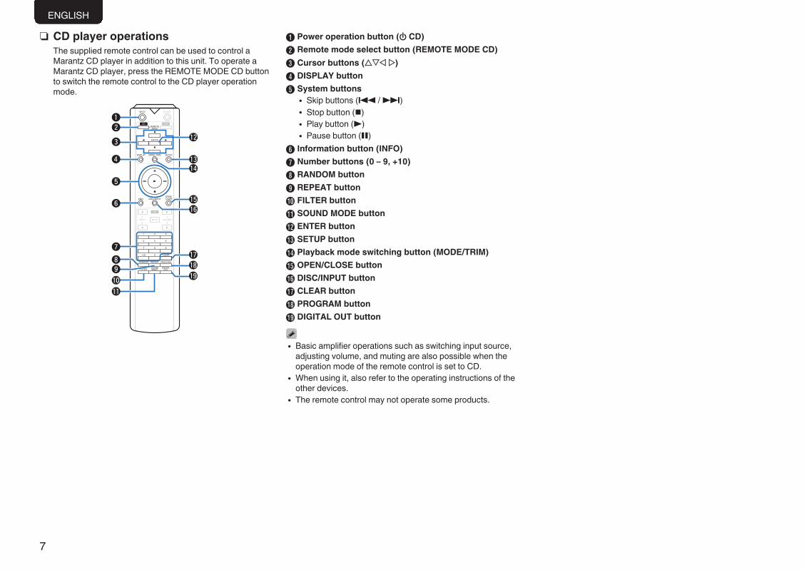
n CD player operationsThe supplied remote control can be used to control aMarantz CD player in addition to this unit. To operate aMarantz CD player, press the REMOTE MODE CD buttonto switch the remote control to the CD player operationmode.
.
qw
e
r
t
u
io
Q0
Q1
y
Q7
Q9
Q8
Q3
Q5Q6
Q2
Q4
A Power operation button (X CD)B Remote mode select button (REMOTE MODE CD)C Cursor buttons (uio p)D DISPLAY buttonE System buttons
0 Skip buttons (8 / 9)0 Stop button (n)0 Play button (1)0 Pause button (3)
F Information button (INFO)G Number buttons (0 – 9, +10)H RANDOM buttonI REPEAT buttonJ FILTER buttonK SOUND MODE buttonL ENTER buttonM SETUP buttonN Playback mode switching button (MODE/TRIM)O OPEN/CLOSE buttonP DISC/INPUT buttonQ CLEAR buttonR PROGRAM buttonS DIGITAL OUT button
0 Basic amplifier operations such as switching input source,adjusting volume, and muting are also possible when theoperation mode of the remote control is set to CD.
0 When using it, also refer to the operating instructions of theother devices.
0 The remote control may not operate some products.
ENGLISH
7
Printing : Color : Black

Connectionsn ContentsConnecting speakers 8Connecting a playback device 10Connecting a recording device 10F.C.B.S. connection 11Connecting a pre-amplifier 15Connecting devices with remote control connectors 16Connecting the power cord 16
NOTE0 Do not plug in the power cord until all connections have
been completed.0 Do not bundle power cords together with connection
cables. Doing so can result in humming or noise.
n Cables used for connectionsProvide necessary cables according to the devices youwant to connect.
Speaker cable.
Audio cable.
R
L
R
L
Balance cable.
R
L
R
L
Remote connectorcable .
Connecting speakersNOTE
0 Disconnect this unit’s power plug from the power outletbefore connecting the speakers.
0 Connect so that the speaker cable core wires do notprotrude from the speaker terminal. The protection circuitmay be activated if the core wires touch the rear panel or ifthe + and - sides touch each other. (“Protectioncircuit” (v p. 27))
0 Never touch the speaker terminals while the power cord isconnected. Doing so could result in electric shock.
0 Use speakers with impedances within the ranges shownbelow to suit how they are used.
Speaker terminalsused on this unit
No. of connectedspeakers
SpeakerImpedance
SPEAKERS A(Standard
connection)2 (one set) 4 – 16 Ω/ohms
SPEAKERS B 2 (one set) 4 – 16 Ω/ohmsSPEAKERS A and
SPEAKERS B 4 (two sets) 8 – 16 Ω/ohmsSPEAKERS A and
SPEAKERS B(Bi-wiring
connection)2 (one set) 4 – 16 Ω/ohms
n Connecting the speaker cablesCarefully check the left (L) and right (R) channels and + (red) and –(black) polarities on the speakers being connected to this unit, and besure to connect the channels and polarities correctly.
1 Peel off about 3/8 inch (10 mm) of sheathing from thetip of the speaker cable, then either twist the core wiretightly or terminate it.
.
2 Turn the speaker terminal counterclockwise to loosen it.
.
3 Insert the speaker cable’s core wire to the hiltinto the speaker terminal.
.
4 Turn the speaker terminal clockwise to tighten it.
.
Spade lug connector
.
When using a banana plugTighten the speaker terminal firmly before inserting the banana plug.
.
ENGLISH
8
OverviewConnections
PlaybackSettings
TipsAppendix
Printing : Color : Black

Speaker connectionThis unit is equipped with two sets of speaker terminals(SPEAKER A and SPEAKER B). One set of speakers can beconnected to each set of terminals, and a total of two sets ofspeakers can be connected.The same signal is output from the SPEAKERS A andSPEAKERS B terminals.When only one set of speakers is to be connected, use eitherthe SPEAKERS A or SPEAKERS B terminals.
.
w qw q
(R) (L)
w qw q
(R) (L)
SPEAKERS A SPEAKERS B
Bi-wiring connectionThis connection limits the effects of signal interferencebetween the high range speakers (tweeters) and low rangespeakers (woofers), allowing you to enjoy high qualityplayback.When bi-wiring with bi-wireable speakers, connect the midand high range terminals to SPEAKERS A (or SPEAKERS B),the low range terminals to SPEAKERS B (or SPEAKERS A).
.
w q
w q
HIGH
LOW
w q
w q
HIGH
LOW
Speaker (R)
Speaker (L)
Remove shorting bar Remove shorting bar Remove shorting bar Remove shorting bar
ENGLISH
9
Printing : Color : Black
Connecting a playbackdevice
You can connect turntables, tuners, CD players and networkaudio players to this unit.Set the phono equalizer of this unit in the "PHONO" section ofthe setting menu according to the type of turntable cartridgeto be connected. (v p. 21)If you set this unit’s input source to “PHONO” and youaccidentally increase the volume without having a turntableconnected, you may hear a hum noise from the speakers.
.
GNDAUDIOOUT
L
R
AUDIOOUT
LR
AUDIOOUT
LR
AUDIOOUT
LR
L
L
R
R
L
L
R
R
L
L
R
R
Network audio playerTuner
Turntable
CD player
NOTE0 The earth terminal (PHONO GND) of this unit is not for safety
grounding purposes. If this terminal is connected when there is a lotof noise, the noise can be reduced. Note that depending on theturntable, connecting the ground line may have the reverse effect ofincreasing noise. In this case, it is not necessary to connect theground line.
0 The PHONO input terminals are equipped with a short pin-plug.Remove this plug to connect a record player. Store the removed shortpin-plug in a safe place so as not to lose it.
About balanced connectorsThis unit has both unbalanced and balanced connectors. Thebalanced connectors have three pins, making it possible totransmit audio signals as a balanced signal, reducing theeffect of external noise. They also have a removable lockmechanism, which reduces shaking in the connector area,making the connection highly reliable.
.
AUDIO OUT
LR
CD player etc.
n Phases of the balanced connectorsThe XLR connector for professional use is internally wired ineither of the following two systems. This unit employs theEuropean system.0 European system (B PIN=HOT C PIN=COLD)
.
1
23 COLD
HOT
GND
0 USA system (B PIN=COLD C PIN=HOT)
.
1
23 HOT
COLD
GND
If a product that employs the USA system is connected withthis unit via a balanced cable, the output signal may bephase-inverted. To correct the inversion, connect the oneside XLR connector reversing the B PIN and C PIN.
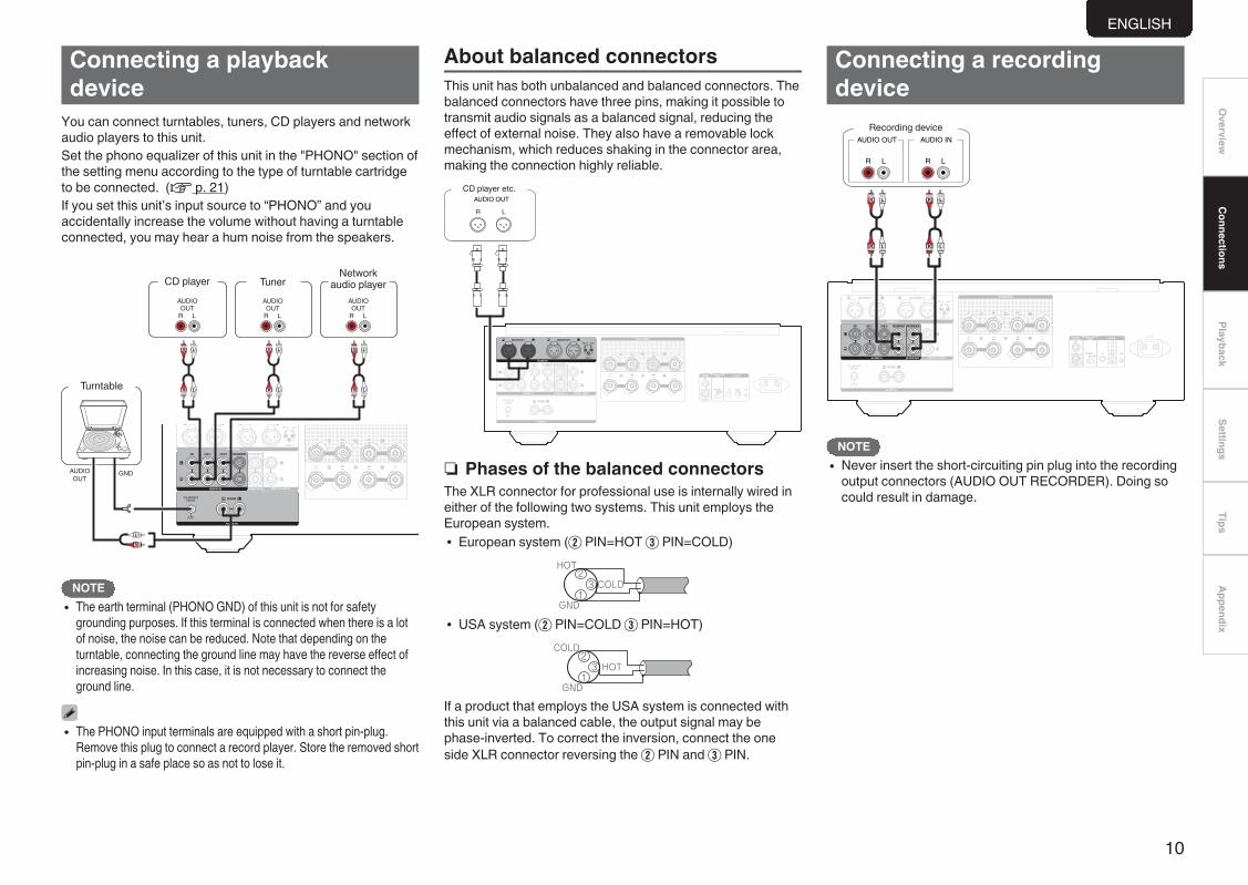
Connecting a recordingdevice
.
LR
L
L
R
R
L
L
R
R
AUDIO OUT
LR
AUDIO IN
Recording device
NOTE0 Never insert the short-circuiting pin plug into the recording
output connectors (AUDIO OUT RECORDER). Doing socould result in damage.
ENGLISH
10
OverviewConnections
PlaybackSettings
TipsAppendix
Printing : Color : Black

F.C.B.S. connectionThe Marantz F.C.B.S. (Floating Control Bus System) is the high quality sound system for link control between multiple PM-10 units (up to 4 units). Each unit is controlled via its ID numberregistered beforehand.The ID numbers need to be set to an operating unit (master) and a subordinate unit (slave) receiving the command from the master. For slave units, register ID numbers in the order of commandreception from the master.Once registered the ID numbers, the units will enable link control operations such as input selection, volume control, on/off selection of muting, display, etc.Furthermore, F.C.B.S. connection of multiple units has the feature that switches this unit's output from stereo to monaural so that the unit can works as a monaural output amplifier. Follow therespective instructions to make the necessary settings.
Preparation for F.C.B.S. connectionn Making the F.C.B.S. connection
To use multiple PM-10 units, make this connection inaddition to audio connection.For details on each connection feature, refer to therespective instructions.Prepare the correct number of portable audio connectioncables for the number of units to be connected. Either ofthe following types of connection cables are adequate.0 Φ3.5 Monaural mini plug O N Φ3.5 monaural mini plug
connecting cable
.
0 Φ3.5 Stereo mini plug O N Φ3.5 stereo mini plugconnecting cable
.
NOTE0 Do not use connecting cables that contain resistance.
n Connection exampleIn the connection of the following example, an unit with IDnumber 1 acts as a master amplifier to control all the otherslave units with ID numbers 2 to 4.
.
ID 1 Master
ID 2 Slave
ID 3 Slave
ID 4 Slave
Signal flow
NOTE0 The PM-10 F.C.B.S. function is only valid between the
same PM-10 models.0 To turn the power of multiple F.C.B.S.-connected units ON/
OFF, switch the power ON in order of lowest to highest IDnumber, and switch the power OFF in order of highest tolowest ID number.
ENGLISH
11
Printing : Color : Black

n How to set ID number for F.C.B.S.When the unit is turned on, the display shows the IDnumber for three seconds.For a master unit, ID number 1 needs to be assigned.For a slave unit, set any of ID numbers 2 to 4.
.
INPUTSELECTOR
X
F.C.B.S. ID
1 While holding F.C.B.S. ID on the rear panel,press X.
2 Turn INPUT SELECTOR on the unit to selectan ID number.
3 Turn the unit off.
4 Again turn the unit on.0 The setting is saved.0 The unit registered as a slave shows “SLAVE” on the
display.
NOTE0 If using this unit by itself as a stereo amplifier, set the ID
number to “0” (Default setting is “0”).0 If the ID number is set to a number other than “0”, this unit
cannot be used for standalone operation.
Stereo complete bi-amp connectionThis mode enables the two amplifiers connected to this unitto function as one monaural amplifier. To use this mode, twoF.C.B.S. connected PM-10 units are required.To switch the mode, use the AMPLIFIER MODE switch onthe rear panel while the power is off.The figures below show example displays in the stereo andbi-amp modes.
.
Stereo mode Bi-amp mode
Bi-amp mode indicator
In bi-amp mode, connect to the left channel input jack. Theright channel input is disabled.The same signals are output from the left and right speakerterminals.
NOTE0 Always turn the power to the unit OFF before changing the
operating mode switch setting. Turning the power ONagain activates the new setting.
0 When in bi-amp mode, the R channel input jacks cannot beused.
0 When in bi-amp mode, the signals input into the L channelare output from both channels. Therefore, the same signalsare output from the L channel and R channel inRECORDER OUT, headphones jack.
0 Speaker systems connected using complete bi-ampconnections must support bi-amp connections. Beforeconnecting your speakers, check in the instruction manualthat came with the speakers or contact the manufacturer toconfirm whether they support bi-amp connection.
ENGLISH
12
OverviewConnections
PlaybackSettings
TipsAppendix
Printing : Color : Black

.
MF / HF
LF
MF / HF
LF
Super Audio CD player, etc.
: Signal flow
Set to “BI-AMP”. Set to “BI-AMP”.
Set PM-10 for L channel to
ID 1
Set PM-10 for R channel to
ID 2To power outlet. To power outlet.
Remove shorting bar
Remove shorting bar
Remove shorting bar
Remove shorting bar
L channel speaker
R channel speaker
ENGLISH
13
Printing : Color : Black

Connection for 5.1 Multi-channel PlaybackThe three units are connected using F.C.B.S. For the F.C.B.S connection, prepare 3 audio connection cables, and refer to F.C.B.S.. (v p. 11)Connect the outputs of players that have 5.1 channel analog outputs to each of the three units.If using an active subwoofer, see the instruction manual that came with the subwoofer for further instructions.Set the ID numbers for the three amplifiers as explained in How to set ID number for F.C.B.S.. (v p. 12)0 When the ID 1 unit is operated, ID 2 and ID 3 units will operate in sync.
.
FRONT R FRONT L SURROUND R
MULTI CHANNEL AUDIO OUT
SURROUND L SUB-WOOFER CENTER
L
LR LR L
R L LR
: Signal flow
Set to “STEREO”. Set to “STEREO”. Set to “STEREO”.For front L/R speakers Set PM-10 to ID 1
For center speaker Set PM-10 to ID 2
For surround speakers Set PM-10 to ID 3
To power outlet.To power outlet.To power outlet.
R CH surround speaker
L CH surround speaker
Front center speaker
R CH front speaker
L CH front speaker
SACD multi-channel player, etc.
ENGLISH
14
OverviewConnections
PlaybackSettings
TipsAppendix
Printing : Color : Black

n Speaker Positioning for Super AudioMulti-channel SoundIn order to enjoy Super Audio CD multi-channel soundwith the best possible acoustics, it is recommended toposition speakers as specified in ITU-R BS.775-1 of theInternational Telecommunication Union (ITU). SuperAudio CD multichannel discs are recorded and mixed soas to achieve the optimum effect with a speaker systemlaid out as specified in ITU-R BS.775-1.0 With Super Audio CD multi-channel discs, the music
signals are basically recorded using 5 channels (3 - 6channels sometimes), but in some cases, LFE (forsubwoofer) is recorded as a sixth channel.
0 Each disc indicates how many channels have beenrecorded on it.
0 The basic layout is 3 speakers in the front and 2 in theback since multi-channel discs usually have 5channels. The 2 front, 1 center and 2 surround (rear)speakers should be set in a circle around the listeningpoint. If using speakers of differing sizes, adjust volumebalance from the amplifier.
0 The location of the subwoofer in the figure is just forexplanatory purposes. It can be located anywhere inthe room. For connection and positioning instructions,see the instruction manual that came with thesubwoofer.
.
60°
Subwoofer Center speaker
Front speaker (Left)
Front speaker (Right)
Rear speaker
(Left Surround)
Rear speaker
(Right Surround)
approx.110°approx.110°
Recommended listening position
0 ITU (International Telecommunication Union)The ITU is a special organization of the United Nations. Itconsists of a number of organs, one of which is the RadioBroadcasting Section.ITU-R BS in the recommendation which consists of standardsrelating to broadcasting (audio) operations, one of which isthe ITU-R BS.775-1 which governs “multi-channel stereosound systems”.
Connecting a pre-amplifierIf you use a pre-amplifier, connect it as shown below, andthen you can use this unit as a power amplifier.
.
LR
L
L
R
R
AUDIOOUT
Pre-amplifier
1 Turn INPUT SELECTOR on the unit to select theinput source to “POWER AMP”.
0 The POWER AMP IN terminals are equipped with a short pin-plug.Remove this plug to connect a pre-amplifier. Store the removed shortpin-plug in a safe place so as not to lose it.
0 You cannot use the input source switching buttons on the remotecontrol unit to select “POWER AMP”.
NOTE0 When the input source is POWER AMP, adjustment of the volume,
muting and balance has no effect. Adjust the volume on the pre-amplifier.
0 When the input source is set to POWER AMP, you cannot use theremote control unit to select the input source.
0 When the input source is POWER AMP, the main unit outputs atmaximum volume. Check the output level on the input device beforeplaying it and adjust the volume accordingly.
ENGLISH
15
Printing : Color : Black

Connecting devices withremote control connectors
Performing operations by RC onthis unit without visual contactYou can connect an external IR receiver to the REMOTECONTROL connectors to perform operations on this unit withthe supplied remote control unit without visual contact. Thismight be necessary if the unit is hidden in a cupboard orcorner, so you can’t directly point with the remote control unitto the device.
.
RC OUT
Infrared retransmitter
Infrared sensor
Remotely connecting Marantz audiodevicesYou can transmit remote control signals simply by connectinga Marantz audio device to the REMOTE CONTROL IN/OUTconnectors using the remote connection cable provided withthe device.Set the remote control switch located on the rear panel of theconnected audio component to “EXTERNAL” to use thisfeature.
.
Connecting the power cordWait until all connections have been completed beforeconnecting the power cord.
.
Power cord (supplied)To household power outlet
(AC 120 V, 60 Hz)
ENGLISH
16
OverviewConnections
PlaybackSettings
TipsAppendix
Printing : Color : Black

Playbackn ContentsTurning the power on 17Selecting the input source 17Adjusting the volume 17Turning off the sound temporarily (Muting) 18Adjusting the left and right channel balance 18Having the display and the illumination lamp off 18Having the illumination lamp always off 18Playing CDs 19Recording 19
.
VOLUME df
REMOTE MODE AMP
MODE/TRIMDISPLAY
INPUT df
MUTE
ui p
AMP X
Turning the power on
1 Press X on the main unit to turn the power on.0 The power indicator lights in blue.0 The standby indicator blinks in red until the unit is
able to be used.
0 Press X AMP on the remote control unit to turn on powerfrom standby mode.
0 You can also turn the INPUT SELECTOR on the main unitwhen the unit is in standby mode to turn on the power.
n Switching the power to standby
1 Press X AMP on the remote control.The unit switches to standby mode, and the STANDBYindicator lights red.
NOTE0 Power continues to be supplied to some of the circuitry
even when the power is in the standby mode. Whenleaving home for long periods of time or when going onvacation, either press X on the main unit to turn off thepower, or unplug the power cord from the power outlet.
Selecting the input source
1 Use INPUT df to select the input source to beplayed back.The selected input source appears on the display.
0 You can also select the input source by turning INPUTSELECTOR on the main unit.
Adjusting the volume
1 Use VOLUME df to adjust the volume.
0 You can also adjust the volume by turning VOLUME on themain unit.
ENGLISH
17
Printing : Color : Black

Turning off the sound temporarily(Muting)
1 Press MUTE.“ATT” appears on the display and the sound is muted.
0 To cancel mute, press MUTE again.
n Setting the attenuation level whensound is muted
The attenuation level can be set at –20 dB, –40 dB, or –∞.0 The factory default setting is –∞.
1 Press and hold MUTE for 2 seconds or longer.The attenuation level will appear on the display.
2 Press MUTE.The attenuation level setting value changes each timethe button is pressed.
0 If not operated for 2 seconds, the current setting is savedand the display returns to normal.
Adjusting the left and right channelbalanceThe volume level of the left and right channels can betrimmed in 0.5 dB steps across a 0.0 - 9.0 dB range.The factory default setting is 0.0 dB (maximum).
1 Press MODE/TRIM.The unit enters the level adjustment mode.0 The left channel level value flashes.
2 Use ui to adjust the left channel level.
3 Press p.The adjustment mode selects the right channel.0 The right channel level value flashes.
4 Use ui to adjust the right channel level.
5 Press MODE/TRIM.The unit exits the adjustment mode.0 If you have connected a “SLAVE” device using the
F.C.B.S. connection (v p. 11), proceed to theslave setting.
Having the display and theillumination lamp offThe display circuit operation can be stopped to minimizenoise from the display and the display circuit which couldinterfere with the analog audio output signal.
1 Press DISPLAY.Each time you press DISPLAY, the display and theillumination lamp (blue) switch on/off at the same time.
0 If you operate the VOLUME knob or another control whenthe display is off, the display turns on again. Whenoperation is finished, the display turns off automaticallyafter approximately 2 seconds.
Having the illumination lamp alwaysoffThe following procedure makes the illumination lamp alwaysoff regardless of the display on/off operation.
1 Press and hold DISPLAY for two seconds andlonger while display is lighted.Press and hold DISPLAY for two seconds and longerwhile the lamp is always off to return to the normalsetting.
ENGLISH
18
OverviewConnections
PlaybackSettings
TipsAppendix
Printing : Color : Black

Playing CDsThis section uses playback from a CD as an example.
1 Press X on this unit to turn the power on.
2 Use INPUT df to switch the input source to“CD”.“CD” is displayed on the display of this unit.
3 Playback the CD.
4 Use VOLUME df to adjust the volume.
RecordingAudio signals input into this unit can be output to an externalrecording device. When recording audio from a playbackdevice connected to this unit, audio can be recorded with theplayback device still connected to this unit.
1 Press X on this unit to turn the power on.
2 Press INPUT df to switch to the input sourcefrom which you want to record.The selected input source is displayed on the display ofthis unit.
3 Recording starts.0 For information on operations, see the owner’s
manual of the recording device.
ENGLISH
19
Printing : Color : Black

SettingsMenu map
By default, this unit has recommended settings defined. You can customize this unit based on your existing system and your preferences.Setting items Description Page
PUREST Sets PUREST mode, the mode with the highest sound quality. This mode restricts noise that may affect sound quality bystopping some of the circuits in this unit.
21
PHONO Sets the phono equalizer of this unit according to the type or impedance of the turntable cartridge to be connected. 21AUTO STBY (Auto Standby)
Sets whether to automatically switch the unit to the standby mode when the unit remains in the stop mode for more than 30minutes.
21
Menu operation
.
uio ENTER
SETUP
1 Press SETUP.The menu is displayed on the display.
2 Use ui to select the menu to be set oroperated, then press ENTER.
3 Use ui to change to desired setting.
4 Press ENTER to enter the setting.0 To return to the previous item, press o.0 Exiting the Menu, press SETUP while the menu is
displayed.The display returns to the normal display.
ENGLISH
20
OverviewConnections
PlaybackSettings
TipsAppendix
Printing : Color : Black

PURESTNoise sources that influence sound quality can besuppressed in order to achieve higher quality playback bystopping all of the following circuits.0 Recording output circuit0 Non-signal state detection circuit0 Headphones circuit
ON: Enables the high sound qualitymode (PUREST mode).
OFF(Default):
Disables the high sound qualitymode (PUREST mode).
0 When PUREST mode is on0 Audio output from the recorder output connectors stops.0 The auto standby function stops working.0 When headphones are connected, the headphones
circuit is activated and the sound output from theheadphones.
PHONOSets the phono equalizer of this unit according to the type orimpedance of the turntable cartridge to be connected.
MM(Default): Set this for an MM cartridge.
MC Low: Use this setting for an MC cartridgeof less than 10 Ω/ohms.
MC High: Use this setting for an MC cartridgeof 10 Ω/ohms or higher.
NOTE0 If this setting change operation is performed, playback
sound is output approximately 10 seconds after thechange. (The standby indicator blinks in red until the unit isable to be used.)
AUTO STBY (Auto Standby)Sets whether to automatically switch the unit to the standbymode when there is no input signal and operation for 30minutes.
On: Enable Auto Standby mode.Off(Default): Disable Auto Standby mode.
0 The display will show the remaining time for three minutesbefore the units enters standby mode.
0 In F.C.B.S. connection, only the ID 1 master unit activatesAuto Standby mode. If the ID 1 master unit is operated withno audio input, set the Auto Standby mode to off.
ENGLISH
21
Printing : Color : Black

Tipsn ContentsTipsI want to adjust the attenuation level when muting sound 23I want to turn the illumination lamps on both sides of theunit main panel off 23I want to use two or more of these units for high qualityplayback 23I want to use this unit’s remote control to operate aMarantz CD player 23I want to use bi-wiring compatible speakers 23I want to use this unit as a power amplifier 23I want to stop some circuits of this unit to enjoy playbackwith higher sound quality 23
TroubleshootingPower does not turn on / Power is turned off 24Operations cannot be performed through the remotecontrol unit 25No sound comes out 25Desired sound does not come out 26Sound is interrupted or noise occurs 26Error messages 26
ENGLISH
22
OverviewConnections
PlaybackSettings
TipsAppendix
Printing : Color : Black

TipsI want to adjust the attenuation level when muting sound0 The attenuation level can be set at –20 dB, –40 dB, or –∞. (v p. 18)I want to turn the illumination lamps on both sides of the unit main panel off0 Turn the illumination lamp setting off. (v p. 18)I want to use two or more of these units for high quality playback0 Use the stereo complete bi-amp connections. (v p. 12)0 Use the multi-channel playback connections. (v p. 14)I want to use this unit’s remote control to operate a Marantz CD player0 Press the REMOTE MODE CD button on the remote control unit to switch the remote control unit to the CD player operation mode. (v p. 7)0 Also, refer to the instruction manual of the CD player.I want to use bi-wiring compatible speakers0 This unit is compatible with bi-wiring connections. Enjoy high quality playback by using bi-wiring connections. (v p. 9)I want to use this unit as a power amplifier0 Connect the pre amplifier to the POWER AMP IN connectors of this unit. (v p. 15)I want to stop some circuits of this unit to enjoy playback with higher sound quality0 Set “PUREST” to “ON” in the menu. (v p. 21)
ENGLISH
23
Printing : Color : Black

TroubleshootingIf a problem should arise, first check the following:1. Are the connections correct?2. Is the set being operated as described in the owner’s manual?3. Are the other devices operating properly?If this unit does not operate properly, check the corresponding symptoms in this section.If the symptoms do not match any of those described here, consult your dealer as it could be due to a fault in this unit. In this case, disconnect the power immediately and contact the store whereyou purchased this unit.
n Power does not turn on / Power is turned offSymptom Cause / Solution Page
Power is not turned on. 0 Check whether the power plug is correctly inserted into the power outlet. 16Power automatically turns off. 0 The Auto Standby mode is on. When approx. 30 minutes pass with no audio input and no operations on the unit, this unit
automatically enters the standby mode. To disable Auto Standby mode, set “AUTO STBY” on the menu to “OFF”.21
Power turns off and the STANDBYindicator flashes in red approx. every 0.5seconds.
0 The protection circuit has been activated due to a rise in temperature within this unit. Turn the power off, wait about an hour until thisunit cools down sufficiently, and then turn the power on again.
27
0 Please re-install this unit in a place having good ventilation. -
0 Check the speaker connections. The protection circuit may have been activated because speaker cable core wires came in contactwith each other or a core wire was disconnected from the connector and came in contact with the rear panel of this unit. Afterunplugging the power cord, take corrective action such as firmly re-twisting the core wire or taking care of the connector, and thenreconnect the wire.
8
0 Turn down the volume and turn on the power again. 170 This unit’s amplifier circuit has failed. Unplug the power cord and contact our customer service center. -
ENGLISH
24
OverviewConnections
PlaybackSettings
TipsAppendix
Printing : Color : Black

n Operations cannot be performed through the remote control unitSymptom Cause / Solution Page
Operations cannot be performedthrough the remote control unit.
0 Batteries are worn out. Replace with new batteries. 20 Operate the remote control unit within a distance of about 23 ft/7 m from this unit and at an angle of within 30°. 20 Remove any obstacle between this unit and the remote control unit. -
0 Insert the batteries in the proper direction, checking the q and w marks. 20 The set’s remote control sensor is exposed to strong light (direct sunlight, inverter type fluorescent bulb light, etc.). Move the set to a
place in which the remote control sensor will not be exposed to strong light.-
0 When using a 3D video device, the remote control unit of this unit may not function due to effects of infrared communicationsbetween units (such as TV and glasses for 3D viewing). In this case, adjust the direction of units with the 3D communicationsfunction and their distance to ensure they do not affect operations from the remote control unit of this unit.
-
0 Press the REMOTE MODE AMP button to switch the remote control operating mode to “AMP”. 6
n No sound comes outSymptom Cause / Solution Page
No sound comes out of speakers. 0 Check the connections for all devices. 80 Insert connection cables all the way in. -
0 Check that input connectors and output connectors are not reversely connected. -
0 Check cables for damage. -
0 Check that speaker cables are properly connected. Check that cable core wires come in contact with the metal part on speakerterminals.
8
0 Securely tighten the speaker terminals. Check speaker terminals for looseness. 80 Check that the proper input source is selected. 170 Adjust the volume. 170 Cancel the muting mode. 180 No sound is output from the speakers when headphones are connected. 4
ENGLISH
25
Printing : Color : Black

n Desired sound does not come outSymptom Cause / Solution Page
No sound comes out of a specificspeaker.
0 Check that speaker cables are properly connected. 80 Adjust the left and right channel balance. 18
The left and right of stereo sound isreversed.
0 Check whether the left and right speakers are connected to the correct speaker terminals. 8
n Sound is interrupted or noise occursSymptom Cause / Solution Page
When playing a record, the sound isdistorted.
0 Adjust to a proper needle pressure. -
0 Check the tip of the needle. -
0 Replace the cartridge. -
When playing a record, a hummingnoise comes out of the speakers.
0 Check that the turntable is connected correctly. 100 If there is a TV or AV device near the turntable, such devices may affect the playback sound. Install the turntable in a location as far
away as possible from the TV or other AV devices.-
When playing a record, a hummingnoise comes out of the speakers whenthe volume is high. (Howlingphenomenon)
0 Install the turntable and speakers as far from each other as possible. 100 The vibrations from the speakers are being transmitted to the player through the floor. Use cushions, etc., to absorb the speakers’
vibrations.-
Error messagesWhen multiple amplifiers are connected by F.C.B.S., the error messages described in the table below may be displayed on the display. In such a case, ID number setting or remote cableconnection may be in failure. Check the ID number or remote cable connection, referring to the table below. For details on ID number setting, see “How to set ID number for F.C.B.S.” (v p. 12).
Indication Meaning Cause / SolutionERROR 02 Multiple amplifiers take ID No.2. 0 Assign different ID numbers to the amplifiers.ERROR 03 Multiple amplifiers take ID No.3.ERROR 04 Multiple amplifiers take ID No.4.ERROR 11 The amplifiers with ID No.2-4 cannot communicate with the amplifier with ID No.1. 0 If the amplifier with ID No.1 is not on, turn it ON.
0 Check that the remote cable is properly connected.ERROR 12 The amplifier with ID No.1 cannot communicate with the amplifiers with ID No.2-4. 0 If multiple amplifiers take ID No.1, set ID numbers properly.
0 If the amplifier with ID No.1 is connected to the amplifier with ID No.0, set IDnumbers properly.
0 Check that the remote cable is properly connected.
ENGLISH
26
OverviewConnections
PlaybackSettings
TipsAppendix
Printing : Color : Black

AppendixExplanation of terms
MM/MC cartridgeThere are two types--MM (Moving Magnet) and MC (MovingCoil)--of cartridges for turntable. As the output levels for thesetwo types of cartridges differ, the setting of the phonoequalizer that is mounted in this unit must be switchedaccording to the type of cartridge for your turntable. Changethis setting in the “PHONO” section of the settingmenu. (v p. 21)Speaker impedanceThis is an AC resistance value, indicated in Ω (ohms).Greater power can be obtained when this value is smaller.Protection circuitThis is a function to prevent damage to devices within thepower supply when an abnormality such as an overload,excess voltage occurs or over temperature for any reason.If a malfunction occurs in this unit, the power indicator blinksred and the unit switches to standby mode.
ENGLISH
27
Printing : Color : Black

Specifications0 RMS Power output (Simultaneous drive of both channels) : 200 W x 2 (8 Ω/ohms load, 1 kHz, T.H.D. 0.05 %)
400 W x 2 (4 Ω/ohms load, 1 kHz, T.H.D. 0.1 %)0 Total harmonic distortion
(1 kHz, simultaneous drive of both channels, 100 W, 8 Ω/ohms load) : 0.005 %0 Frequency response (CD, 1 W, 8 Ω/ohms load) : 5 Hz – 50 kHz ±3 dB0 Damping factor (8 Ω/ohms load, 20 Hz – 20 kHz) : 5000 Input sensitivity/Input impedance
PHONO (MC Low) : 280 μV/10 Ω/ohmsPHONO (MC High) : 280 μV/49 Ω/ohmsPHONO (MM) : 2.6 mV/47 kΩ/kohmsBALANCED : 880 mV/40 kΩ/kohmsCD/LINE/RECORDER : 440 mV/20 kΩ/kohmsPOWER AMP : 1.5 V/20 kΩ/kohms
0 Maximum allowable PHONO input level (1 kHz)MC : 8 mVMM : 80 mV
0 RIAA deviation (20 Hz – 20 kHz) : ±0.5 dB0 S/N (IHF-A, 8 Ω/ohms load)
PHONO (MC) : 76 dB (0.5 mV Input, 1 W Output)PHONO (MM) : 88 dB (5 mV Input, 1 W Output)BALANCED : 111 dB (4 V Input, Rated output)CD/LINE/RECORDER : 111 dB (2 V Input, Rated output)
0 Power requirement : AC 120 V, 60 Hz0 Power consumption : 270 W0 Power consumption in standby mode : 0.3 W
For the purpose of improvement, the specifications and design are subject to change without notice.
ENGLISH
28
OverviewConnections
PlaybackSettings
TipsAppendix
Printing : Color : Black

n Dimensions (Unit : in. (mm))
.
17 3/8 (440)
3/4
(18)
1/4
(4)
5 3/
4 (1
46)
6 5/
8 (1
68)
12 (302)15
3/4
(40
0)
17 7
/8 (
453)
3/4
(19)
1 3/
8 (3
4)
10 1
/2 (
266)
2 5/
8 (6
6)2
3/4
(68)
2 3/4 (69) 2 3/4 (69)
2 3/4 (67)
n Weight : 46 lb 15 oz (21.3 kg)
ENGLISH
29
Printing : Color : Black

Indexv A
Auto Standby mode ............................................................. 21
v BBi-wiring ................................................................................ 9
v CCD player ...................................................................... 10, 19
v DDisplay brightness ............................................................... 18
v FF.C.B.S. ............................................................................... 11Front panel ............................................................................ 4
v IInput source ......................................................................... 17
v MMenu map ........................................................................... 20Muting ................................................................................. 18
v NNetwork audio player ........................................................... 10
v PProtection circuit .................................................................. 27
v RRear panel ............................................................................. 5Recording device ................................................................ 10Remote control .................................................................... 16Remote control unit ............................................................... 6
v SSpeaker impedance ............................................................ 27Speakers ............................................................................... 8
v TTips ..................................................................................... 23Troubleshooting .................................................................. 24Tuner ................................................................................... 10Turntable ............................................................................. 10
v VVolume ................................................................................ 17
ENGLISH
30
OverviewConnections
PlaybackSettings
TipsAppendix
Printing : Color : Black

Printed in Japan 5411 11349 00AMCopyright © 2017 D&M Holdings Inc. All Rights Reserved.
31
Printing Color : Black