insulation breakdown test set an/gsm-6
TRANSCRIPT

TM 11-6625-273-35
D E P A R T M E N T O F T H E A R M Y T E C H N I C A L M A N U A L
F I E L D A N D D E P O T
M A I N T E N A N C E
I N S U L A T I O N
B R E A K D O W N
T E S T S E T
A N / G S M - 6
T h i s c o p y i s a r e p r i n t w h i c h i n c l u d e s c u r r e n t
p a g e s f r o m C h a n g e s 1 and 2.
H E A D Q U A R T E R S , D E P A R T M E N T O F T H E A R M Y
J U L Y 1 9 5 9
WARNING
DANGEROUS VOLTAGES EXIST IN THIS EQUIPMENT
Be extremely careful when working on this equipment. Seriousinjury or death may result if safety precautions are not observed.
B E S U R E T H E E Q U I P M E N T I S C O M P L E T E L Y
D I S C H A R G E D B E F O R E M A K I N G A N Y R E P A I R S .
D O N ’ T T A K E C H A N C E S !
V O L T A G E S A S H I G H A S 4 0 , 0 0 0 V O L T S M A YE X I S T A T T H E F O L L O W I N G P L A C E S :
O U T P U T T E R M I N A L SO U T P U T C A B L E
H I G H - V O L T A G E R E C T I F I E R


C h a n g e s i n f o r c e : C 1 a n d C 2
T M 1 1 - 6 6 2 5 - 2 7 3 - 3 5
C 2
H E A D Q U A R T E R SDEPARTMENT OF THE ARMY,
W A S H I N G T O N , DC, 3 March 1986
F ie ld and Depot Main tenance ManualT E S T S E T S , I N S U L A T I O N B R E A K D O W N A N / G S M - 6
A N D A N / G S M - 6 A
N o . 2
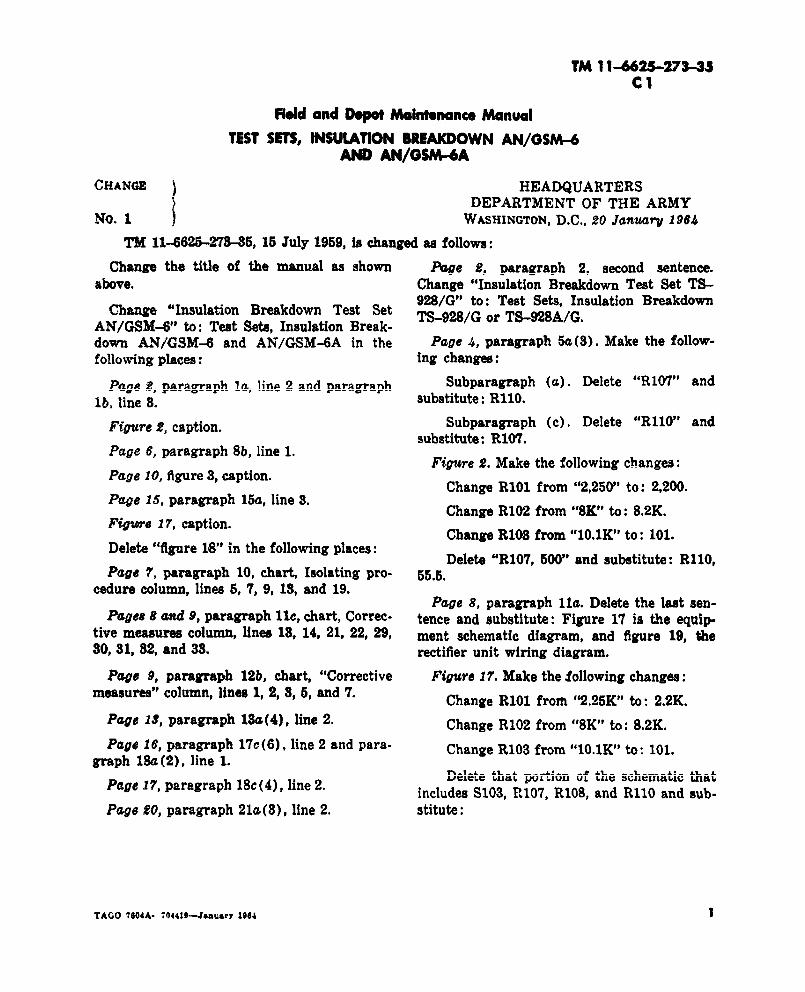
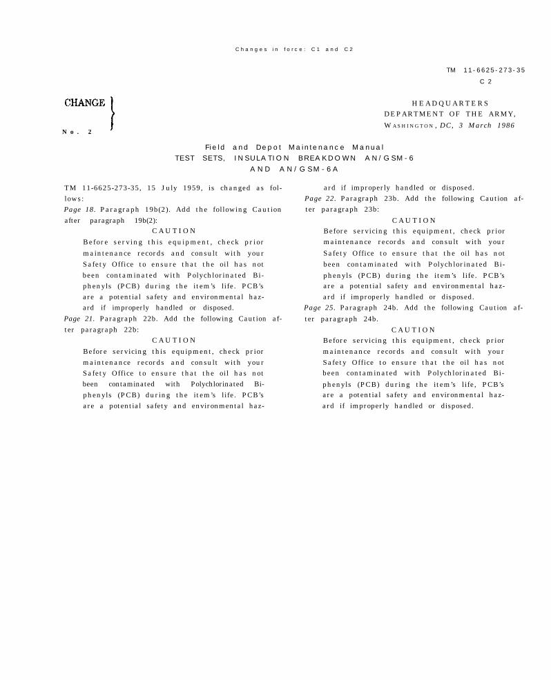
TM 11-6625-273-35, 15 July 1959, is changed as fol-lows:Page 18. Paragraph 19b(2). Add the following Cautionafter paragraph 19b(2):
C A U T I O N
Before serving this equipment, check prior
maintenance records and consult with yourSafety Office to ensure that the oil has notbeen contaminated with Polychlorinated Bi-phenyls (PCB) during the item’s life. PCB’sare a potential safety and environmental haz-ard if improperly handled or disposed.
Page 21. Paragraph 22b. Add the following Caution af-ter paragraph 22b:
C A U T I O N
Before servicing this equipment, check priormaintenance records and consult with yourSafety Office to ensure that the oil has notbeen contaminated with Polychlorinated Bi-phenyls (PCB) during the item’s life. PCB’sare a potential safety and environmental haz-
ard if improperly handled or disposed.Page 22. Paragraph 23b. Add the following Caution af-ter paragraph 23b:
C A U T I O NBefore servicing this equipment, check priormaintenance records and consult with your
Safety Office to ensure that the oil has notbeen contaminated with Polychlorinated Bi-
phenyls (PCB) during the item’s life. PCB’sare a potential safety and environmental haz-ard if improperly handled or disposed.
Page 25. Paragraph 24b. Add the following Caution af-
ter paragraph 24b.C A U T I O N
Before servicing this equipment, check priormaintenance records and consult with yourSafety Office to ensure that the oil has notbeen contaminated with Polychlorinated Bi-
phenyls (PCB) during the item’s life, PCB’sare a potential safety and environmental haz-ard if improperly handled or disposed.


By Order of the Secretary of the Army:
JOHN A. WICKHAM JR.General, United States Army
Chief of S t a f f
R. L . DILWORTHBrigadier General, United States Army
The Adjutant General
DISTRIBUTION:T o b e d i s t r i b u t e d i n a c c o r d a n c e w i t h D A F o r m 1 2 - 3 6 l i t e r a t u r e
r e q u i r e m e n t s f o r A N / G S M - 6 , - 6 A .
This publication Is required for official we or foradminls$mtiwe or oporutioncd purpoees only. Distribution islimited *O US ~vernment Agencies. Other requ~ts fw fhisdwuwn~ must b refamrod *e Cammmwkw. US Armytimmuniatio*Elwtmnia Command end Forf Monmou*h,AWN: A~EL-ME-P, Fort Monmoutln, NJ 07703-5007.

CHAPTER 2.
CHAPTER 3.
Section I.
1
TECHNICAL MANUAL
No. 11-6625-273-35
TM 11-6625-273-35
H E A D Q U A R T E R S ,D E P A R T M E N T O F T H E A R M Y
W ASHINGTON 25, D. C., 15 July 1969
CHAPTER 1.
S e c t i o n I .
I I .
I I .
CHAPTER 4.
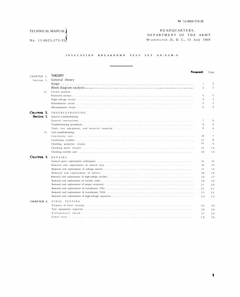
I N S U L A T I O N B R E A K D O W N T E S T S E T A N / G S M - 6
THEORYGeneral theoryScope . . . . . . . . . . . . . . . . . . . . . . . . . . . . . . . . . . . . . . . . . . . . . . . . . . . . . . . . . . . . Block diagram analysisCircuit analysis
Protective circuits . . . . . . . . . . . . . . . . . . . . . . . . . . . . . . . . . . . . . . . . . . . . . . . . . . . . . . . . . . . . . . . . . . . . . . .
High-voltage circuit . . . . . .. . . . . . . . . . . . . . . . . . . . . . . . . . . . . . . . . . . . . . . . . . . . . .
Kilovoltmeter circuit . . . . . . . . . . . . . . . . . . . . . . . . . . . . . . . . . . . . . . . . . . . . . . . . . . . . . . . .
Microammeter circuit . . . . . . . . . . . . . . . . . . . . . . . . . . . . . . . . . . . . . . . . . . . . . . . . . . . . . . . .
T R O U B L E S H O O T I N G
General troubleshooting
General instructions . . . . . . . . . . . . . . . . . . . . . . . . . . . . . . . . . . . . . . . . . . . .
Troubleshooting procedures . . . . . . . . . . . . . . . . . . . . . . . . . . . . . . . . . . . . . . . . . .. . .. . . . . . . .
Tools, test equipment, and material required . . . . . . . . . . . . . . . . . . . . . . . . . . . . . . .
Unit troubleshooting
Cont inu i ty t es t . . . . . . . . . . . . . . . . . . . . . . . . . . . . . . . . . . . . . . . . . . .
Localizing troubles . . . . . . . . . . . . . . . . . . . . . . . . . . . . . . . . . . . . . . . . . . . . . . . . . .
Checking protective circuits
Checking meter circuits . . . . . . . . . . . . . . . . . . . . . . . . . . . . . . . . . . . . . . . . . . . . . . . .
Checking rectifier unit . . . . . . . . . . . . . . . . . . .. . . . . . . . . . . . . . . . . . . . . . . . . . . . . . . . . . . . . . . . . . . . . .
R E P A I R S
General parts replacement techniquies . . . . . . . . . . . . . . . . . . . . . . . . . . . . . . . . . . . . . . . . . . . . . . . .
Removal and replacement of control unit . . . . . . . . . . . . . . . . . . . . . . . . . . . . . . . . . . . .
Removal and replacement of voltage control . . . . . . . . . . . . . . . . . . . . . . . . . . . . . . . . . . . . . . . . . . . . . .
Removal and replacement of meters . . . . . . . . . . . . . . . . . . . . . . . . . . . . . . . . . . .
Removal and replacement of high-volhge rectifier. . . . . . . . . . . . . . . . . . . . . . . . . . . . . . . . . . . . . . . . . . . . . . .
Removal and replacement of rectifier tubes. . . . . . . . . . . . . . . . . . . . . . . . . . . . . . . . . . . . . . . . . . . . . . . . . . . . . .
Removal and replacement of output terminals . . . . . . . . . . . . . . . . . . . . . . . . . . . . . . . . . . . . . . . . . . . . . . . . . . .
Removal and replacement of transformer T201 . . . . . . . . . . . . . . . . . . . . . . . . . . . . . . . . . . . . . . . . . . . . . . .
Removal and replacement of transformer T2O2 . . . . . . . . . . . . . . . . . . . . . . . . . . . . . . . . . . . . . . . . . . . . . . .
Removal and replacement of high-voltage capacitors . . . . . . . . . . . . . . . . . . . . . . . . . . . . . . . . . . . . . . . . . . . .
F I N A L T E S T I N G
Purpose of final testing . . . . . . . . . . . . . . . . . . . . . . . . . . . . . . . . . . . . . . . . . . . .
Test equipment required . . . . . . . . . . . . . . .. . . . . . . . . . . . . . . . . . . . . . . . . . . . . . . .
P r e l i m i n a r y c h e c k . . . . . . . . . . . . . . . . . . . . . . . . . . . . . . . . . . .
F ina l t e s t s . . . . . . . . . . . . . . . . . . . . . . . . . . . . . . . . . . . . . . . . . . . . .
1
2
3
4
5
6
7
8
9
10
1112
13
14
15
16
17
1 8
1 9
2 0
2 1
2 2
2 3
2 4
2 5
2 6
2 7
2 8
Page
2
2
2
3
3
4
6
6
6
7
8
9
1 3
1 4
15
1 5
1 5
1 6
1 7
1 9
2 0
2 1
2 1
2 5
2 6
2 6
2 6
2 6

C H A P T E R 1
T H E O R Y
S e c t i o n I . G E N E R A L T H E O R Y
1 . S c o p e
a. This manual covers field and depot main-
t e n a n c e f o r I n s u l a t i o n B r e a k d o w n T e s t S e tA N / G S M - 6 . I t i n c l u d e s i n s t r u c t i o n s a p p r o -pr iate to third , fourth, and f i f th echelons fort r o u b l e s h o o t i n g , t e s t i n g , a n d r e p a i r i n g t h e
equipment , and replac ing maintenance parts .It also lists tools, materials, and test equipmentfor third, fourth, and fifth echelon maintenance.Detai led funct ions o f the equipment are cov-ered in the theory section.
b. The complete manual for this equipmentincludes one other publ icat ion, TM 11-6625-2 7 3 - 1 2 , I n s u l a t i o n B r e a k d o w n T e s t S e t A N /
GSM-6, Operat ion and Organizat ional Mainte-nance.
c. Forward comments concerning this man-ual to the Commanding Officer, United StatesArmy Signal Publ icat ions Agency , Fort Mon-mouth, N. J .
Note. For applicable forms and records, see para-graph 2, TM 11-6625-273-12.
2. Block Diagram Analysis(fig. 1)
The test set supplies high-value direct cur-rent (dc ) vo l tages for test ing the insulat ionq u a l i t i e s o f e l e c t r i c a l i n s u l a t o r s . T h e m a i n
c o m p o n e n t o f t h e e q u i p m e n t i s I n s u l a t i o nBreakdown Test Set TS-928 /G ( tester ) , whichcontains a control unit and a rectifier unit. The
contro l unit contains the contro l c i rcuit andmetering circuit; the rectifier unit contains theoil-immersed high-voltage rectifier and doubler
circuit.
a. The input power is applied to the test set
through the control circuit, The control circuit
feeds the power to the h igh-vo l tage rect i f ierand doubler, which provides the dc voltage forp e r f o r m i n g t h e r e q u i r e d t e s t s ( T M 1 1 - 6 6 2 5 -2 7 3 - 1 2 ) .
b. The metering circuit indicates the output
voltage of the tester, and the amount of leak-age current through the dielectric (insulation)o f t h e t e s t s p e c i m e n . C o n n e c t i o n t o e a r t hg r o u n d i s m a d e t h r o u g h a c o n n e c t o r o n t h e
rectifier unit.
Figure 1. Insulation breakdown test set TS-928/G-block diagram.
S e c t i o n I I . C I R C U I T A N A L Y S I S
3. Protective Circuits s o u r c e , a n d g r o u n d c a b l e W 2 0 1 m a k e s g o o d(fig. 17) connection to both the equipment and to earth
The protec t ive c i rcu i ts prevent power f rom ground. When power i s appl ied to the tester ,
being applied to the equipment until all power the source voltage is fed to relay K101 circuit,
connect ions are complete and correct ly po lar - voltage control T101, and filament transformer
ized. T202.
a. Power can be applied to the tester when ( 1 ) I n t h e O N p o s i t i o n , c i r c u i t b r e a k e rb o t h s i d e s o f I N C O R R E C T P O L A R I T Y i n d i - switch CB101 completes the circuit tocater DS103 are at ground potent ia l . Under I N P U T V O L T A G E i n d i c a t o r I ) S 1 0 1this condition, terminal 1 of input cable W101 and f i lament transformer T202. Thec o n n e c t s t o t h e g r o u n d s i d e o f t h e p o w e r filaments of rectifier tubes V201 and
2
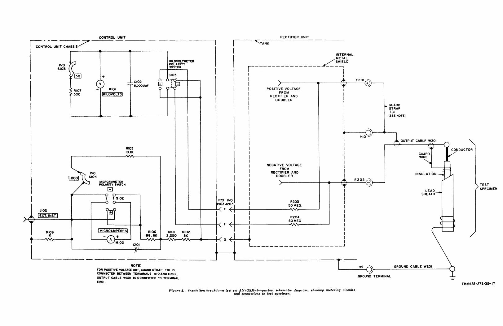
Figure 2.
TM 6625-273-35-17
V 2 0 2 h e a t u p a n d t h e h i g h - v o l t a g eoutput can be obtained.
W h e n p r e s s e d , h i g h - v o l t a g e p u s hswitch S101 completes the c ircuit torelay K101. Relay K101 energizes andapplies the source voltage to OUTPUT
V O L T A G E i n d i c a t o r D S 1 0 2 a n d t ovoltage control T101.
Adjust ing the pos i t ion o f the arm ofvoltage control T101 adjusts the volt-
a g e t h a t i s a p p l i e d t o h i g h - v o l t a g e
transformer T201, thereby adjust ing
the dc voltage output of the rectifier.
b. P o w e r c a n n o t b e a p p l i e d t o t h e t e s t e runder the following conditions.
If terminal 2 of input cable W101 isconnected to the ground s ide o f thepower source (ground cable W201 con-nected to earth ground) , the sourcevoltage is applied only across INCOR-
R E C T P O L A R I T Y i n d i c a t o r D S 1 0 3 .G r o u n d c o n n e c t i o n i s m a d e t o b o t hs i d e s o f t h e r e l a y c i r c u i t , a n d t h e
tester cannot be operated.
If ground cable W201 is not connectedto earth ground, or makes poor groundconnection, or is not connected to theequipment, both sides of INCORRECTP O L A R I T Y i n d i c a t o r D S 1 0 3 a r e n o ta t g r o u n d p o t e n t i a l , a n d i n d i c a t o rDS103 is placed in series with the pri-m a r y o f f i l a m e n t t r a n s f o r m e r T 2 0 2 .
This ser ies combinat ion is thereforei n p a r a l l e l w i t h I N P U T V O L T A G Eindicator DS101. When circuit breakerswitch CB101 is operated, both indi -
c a t o r s ( D S 1 0 1 a n d D S 1 0 3 ) l i g h t(DS103 with less bri l l iance) , indicat-
ing a poor or no ground connection. If
c i r c u i t b r e a k e r s w i t c h C B 1 0 1 a n dh i g h - v o l t a g e p u s h s w i t c h S 1 0 1 a r eboth operated, relay K101 is placed inseries with indicator DS103, l imit ingthe current flow and preventing relay
K101 from operat ing .
4 . H i g h - v o l t a g e C i r c u i t
( f ig. 17)
The high-vo l tage c ircui t consists o f an o i l -immersed high-voltage rectifier and doubler anda guard c ircui t .
a. High-voltage Rectifier and Doubler.
( 1 )
( 2 )
( 3 )
The outputs o f rect i f ier tubes V201and V202 charge capacitors C201 andC 2 0 2 t h r o u g h c u r r e n t l i m i t i n g r e -sistor R205 and R206. Resistors R201.and R202 are bleeder resistors throughwhich capacitors C201 and C202 dis-c h a r g e w h e n t h e e q u i p m e n t i s s h u td o w n .With guard strap TB1 connected be-t w e e n p o s i t i v e ( + ) o u t p u t t e r m i n a lE201 and guard terminal H10, a nega-
t ive vo l tage output i s obta ined f romnegat ive ( - ) output terminal E202.With guard strap TB1 connected be-t w e e n n e g a t i v e ( - ) o u t p u t t e r m i n a lE202 and guard terminal H10, a posi-t ive vo l tage output i s obta ined f romposi t ive (+) output terminal E201
b. Guard Circui t . T h e g u a r d c i r c u i t w h i c hconsists o f the internal metal shie ld and theexternal guard c ircuit components is used top r e v e n t l e a k a g e c u r r e n t s f r o m e n t e r i n g t h emetering circuit.
( 1 )
( 2 )
Leakage currents within the rectifier
unit are iso lated from the meter ingc ircuit by the internal metal shie ld .The internal metal shield is connected
to the transformer cores, the capacitors u p p o r t p l a t e s ( f i g . 1 3 ) , a n d o t h e rmetal parts to which leakage currentsmight f low.
L e a k a g e c u r r e n t s b e t w e e n t h e c o n -ductor and the lead sheath (or outercas ing) o f the test spec imen ( f ig . 2 )are fed to the current metering circuit
(par. 6), Leakage currents on the sur-face of the insulation of the test speci-men are shunted through the guard
connector (fig. 17), the terminal strap,and guard terminal H10 to the internalmetal shield.
5. Kilovoltmeter Circuit
Kilovoltmeter M101 indicates the dc voltageoutput of the tester.
a. Negative Voltage Output. When the tester
is supply ing a negat ive vo l tage output (par ,4a (2)), kilovoltmeter polarity switch S105 (fig.2) is placed in the negative (-) position, plac-ing the kilovoltmeter circuit in the output cir-cuit as follows:
3

( 1 )
( 2 )
( 3 )
The negative terminal of kilovoltmeterM101 is connected, through multiplierresistor R204, to negative (-) output,terminal E202 of the rectifier unit.The positive terminal of kilovoltmeterM101 is connected, through the inter-
nal metal shie ld , to guard terminalH10 of the rectifier unit.
V O L T M E T E R R A N G E s w i t c h S 1 0 3(fig. 17) places shunt resistance acrosskilovoltmeter M101.
( a )
( b )
( c )
( d )
( 4 )
( 5 )
I n t h e 5 0 p o s i t i o n , t h e m e t e r i sshunted by res istor R107 and canindicate up to 50 kilovolts.
I n t h e 2 5 p o s i t i o n , t h e m e t e r i sshunted by res istor R108 and canindicate up to 25 kilovolts.I n t h e 1 0 p o s i t i o n , t h e m e t e r i sshunted by res istor R110 and canindicate up to 10 kilovolts.In the 5 position, the meter is notshunted and can indicate up to 5kilovolts.
Capacitor C102 protects kilovoltmeterM101 against current surges.
Glow lamp E102, which has a f ir ingpotential of approximately 90 volts dc,protects kilovoltmeter M101 from ex-cess ive vo l tages as fo l lows :
( a )
( b )
T h e s e r i e s c i r c u i t , c o n s i s t i n g o f
glow lamp E102 and resistor R203,i s i n p a r a l l e l w i t h k i l o v o l t m e t e rM101. Under normal output condi -tions, the voltage across this circuitis less than 90 volts and the lampdoes not fire.If the circuit is exposed to an exces-sive voltage, the voltage impressedon glow lamp E102 exceeds 90 voltsdc and the glow lamp conducts. Theconduction through the parallel pathincreases the current flow throughmultiplier resistor R204, increasingt h e v o l t a g e d r o p a c r o s s r e s i s t o rR204, and limiting the voltage ap-plied to kilovoltmeter M101.
b. Positive Voltaqe Output. When the tester
is supply ing a pos i t ive vo l tage output (par .4 a ( 3 ) ) , k i l o v o l t m e t e r p o l a r i t y s w i t c h S 1 0 5
(fig. 2) is placed in the positive (+) position,placing the kilovoltmeter circuit across the out-put circuit as follows:
4
( 1 )
( 2 )
( 3 )
( 4 )
( 5 )
The positive terminal of kilovoltmeterM101 is connected, through multiplierres istor R203, to pos i t ive (+) outputterminal E201 of the rectifier unit.
The negative terminal of kilovoltmeterM101 is connected, through the inter-nal metal shie ld , to guard terminalH10 of the rectifier unit.
V O L T M E T E R R A N G E s w i t c h S 1 0 3funct ions in the same manner as de-
scribed in a(3) above.
Capacitor C102 protects kilovoltmeterM101 against current surges.
G l o w l a m p E 1 0 2 p r o t e c t s k i l o v o l t -meter M101 from excessive voltage inthe same manner as described in a(5)a b o v e , e x c e p t t h a t t h e f u n c t i o n s o fresistors R203 and R204 are reversed.
6. Microammeter Circuit
M i c r o a m m e t e r M 1 0 2 i n d i c a t e s t h e o u t p u t
(charg ing) current o f the tester , or the d is -charging current of the test specimen.
a. Negative Output. When the tester is sup-ply ing a negat ive vo l tage output (par . 4a(2) ) ,microammeter po lar i ty switch S102 ( f ig . 2 ) i s
p l a c e d i n t h e n e g a t i v e ( - ) p o s i t i o n , p l a c i n gthe microammeter circuit in series with the out-put circuit as follows:
( 1 )
( 2 )
( 3 )
T h e n e g a t i v e t e r m i n a l o f m i c r o a m -meter M102 is connected, through cur-rent limiting resistor R109, to the con-
trol unit chassis which is connected toearth ground.
The pos i t ive terminal o f microamme-ter M102 is connected to positive (+)output terminal E201 through currentl i m i t i n g r e s i s t o r s R 1 0 6 , R 1 0 1 , a n dR 1 0 2 , t h r o u g h t h e i n t e r n a l m e t a lshie ld , through guard terminal H10,
and through guard strap TB1.A M M E T E R M U L T I P L I E R s w i t c h
S104 (fig. 17) places shunt resistanceacross both microammeter M102 and
current l imit ing res istor R106.(a) In the 1000 position, the meter and
r e s i s t o r R 1 0 6 a r e s h u n t e d b y r e -
sistor R103, and the meter can indi-
cate up to 50 ,000 microampere .(b) In the 100 posit ion, the meter and
r e s i s t o r R 1 0 6 a r e s h u n t e d b y r e -

sister R104, and the meter can indi-
cate up to 5 ,000 microampere .
(c) In the 10 posit ion, the meter andresistor R106 are shunted by theseries combination of resistors R104and R105, and the meter can indi-
cate up to 500 microampere .( d ) I n t h e 1 p o s i t i o n , t h e m e t e r a n d
resistor R106 are not shunted, andt h e m e t e r c a n i n d i c a t e u p t o 5 0
microamperes .
(4) The charging current flows from nega-t i v e ( - ) o u t p u t t e r m i n a l E 2 0 2 ,t h r o u g h t h e t e s t s p e c i m e n t o e a r t hg r o u n d , t h r o u g h t h e m e t e r c i r c u i t
( (1) , (2 ) , and (3) above) , to posit ive
( + ) o u t p u t t e r m i n a l E 2 0 1 .(5 ) To measure d ischarging current (dur-
ing shutdown), microammeter polarityswitch S102 is placed in the positive
( + ) p o s i t i o n . T h e e n e r g y c o n t a i n e di n t h e i n s u l a t i o n ( d i e l e c t r i c ) o f t h etest spec imen becomes the source o fpower , and the current f lows in theopposite direction from that describedi n ( 4 ) a b o v e .
( 6 ) D u r i n g e i t h e r n e g a t i v e o r p o s i t i v eoutput , the meter protect ive c i rcui toperates as fo l lows :
(a ) C a p a c i t o r C 1 0 1 ( f i g . 1 7 ) p r o t e c t smicroammeter M102 against current
s u r g e s ; s p a r k g a p E 1 0 6 g r o u n d s
spurious voltage pulses.
(b ) D C O V E R L O A D i n d i c a t o r E 1 0 1( g l o w l a m p ) , w h i c h h a s a f i r i n gpotential of approximately 90 voltsd c , p r o t e c t s m i c r o a m m e t e r M 1 0 2from excess ive currents ( caused by
a die lectr ic breakdown in the tests p e c i m e n ) . U n d e r n o r m a l o u t p u tc o n d i t i o n s , t h e v o l t a g e a c r o s s r e -sistor R102 is less than 90 volts dc
and the g low lamp does not f i re .Under excessive current conditions,
h o w e v e r , t h e i n c r e a s e d c u r r e n t
t h r o u g h r e s i s t o r R 1 0 2 r a i s e s t h evoltage to more than 90 volts dc, the
glow lamp conducts, shunts the ex-c e s s i v e c u r r e n t a r o u n d t h e m e t e rcircuit, and limits both the currenta n d v o l t a g e a p p l i e d t o t h e m e t e r
c ircui t .b. Pos i t ive Output . When the tester i s sup-
ply ing a pos i t ive vo l tage output (par . 4a(3) ) ,
microammeter po lar i ty switch S102 ( f ig . 2 ) i s
placed in the positive (+) position, placing themicroammeter circuit in series with the output
c ircuit as fo l lows:(1) The posit ive terminal o f microamme-
ter M102 is connected, through currentlimiting resistor R109, to the control
u n i t c h a s s i s w h i c h i s c o n n e c t e d t oearth ground.
(2 ) The negat ive terminal o f microamme-ter M102 is connected to negative (-)
output terminal E202 through currentl i m i t i n g r e s i s t o r s R 1 0 1 , R 1 0 2 , a n dR 1 0 6 , t h r o u g h t h e i n t e r n a l m e t a l
shie ld , through guard terminal H10,and through guard strap TB1.
( 3 ) A M M E T E R M U L T I P L I E R s w i t c hS104 functions in the same manner asdescr ibed in a (3) above .
(4) The charging current-flows from nega-t i v e ( - ) o u t p u t - t e r m i n a l E 2 0 2 ,t h r o u g h t h e m e t e r c i r c u i t ( ( 1 ) , ( 2 ) ,
and (3) above) , and through the testspecimen insulat ion, to posit ive (+)
output terminal E201.(5 ) To measure d ischarging current (dur-
ing shutdown), microammeter polarityswitch S102 is placed in the negative
(-) position. The energy containedi n t h e i n s u l a t i o n ( d i e l e c t r i c ) o f t h etest spec imen becomes the source o fpower , and the current f lows in the
direction opposite from that describedin (4 ) above .
5
C H A P T E R 2
T R O U B L E S H O O T I N G
S e c t i o n I . G E N E R A L T R O U B L E S H O O T I N G
Warning: When troubleshooting or mak-ing repairs in this equipment, be extremelycareful of the high voltages. Allow the testerto discharge completely before making anyrepairs. Always disconnect the input and out-put cables from the tester before touching anyinternal part. Failure to follow safety pre-
cautions may result in injury or death.
7 . General Instructions
Troubleshoot ing at f ie ld and depot mainte-
nance level includes all the techniques outlinedfor organizat ional maintenance (TM 11-6625-2 7 3 - 1 2 ) a n d a n y s p e c i a l o r a d d i t i o n a l t e c h -niques required to isolate a defective part. The
field and depot maintenance procedures are notcomplete in themselves, but supplement the pro-c e d u r e s d e s c r i b e d i n o r g a n i z a t i o n a l m a i n t e -nance . The systemat ic t roubleshoot ing proce -dure , which begins with the equipment per -formance checks that can be performed at ano r g a n i z a t i o n a l l e v e l , m u s t b e c o m p l e t e d b ymeans of sectionalizing, localizing, and isolating
techniques.
8. Troubleshooting Procedures
a. General. The first step in servicing a de-fective test set is to sectionalize the fault. Sec-tionalization means tracing the fault to a majorcomponent. The second step is to localize thefault . Local izat ion means tracing the fault toa defect ive part responsib le for the abnormalcondition. Some faults, such as burned-out re-sistors and arcing or shorted transformers canoften be located by sight, smell, and hearing,The majority of faults, however, must be local-ized by checking voltages and resistances.
b. Sectionalization. I n s u l a t i o n B r e a k d o w nTest Set AN/GSM-6 consists of two major
units: the control unit and the rectifier unit,The first step in tracing trouble is to locate theunit at fault by the following methods:
(1) Visual inspec t ion . The purpose of vis-
ual inspection is to locate faults with-
( 2 )
out testing or measuring circuits. Allmeter indications or other visual signs
s h o u l d b e o b s e r v e d a n d a n a t t e m p tmade to sectionalize the fault to a par-
ticular unit.
Operat ional t e s t s . O p e r a t i o n a l t e s t sfrequent ly indicate the general loca-
t i o n o f t r o u b l e . I n m a n y i n s t a n c e s ,the tests will help in determining theexact nature of the fault. Refer to thee q u i p m e n t p e r f o r m a n c e c h e c k l i s t(TM 11-6625-273-12)
c. Localization and Isolation. The tests listedbelow wil l a id in locat ing and isolat ing thetrouble. First, localize the trouble to a singlecircuit, and then isolate the trouble within that
circuit by resistance measurements.
( 1 )
( 2 )
( 3 )
Resistance measurements. These
measurements will help isolate the in-dividual component part at fault. Usethe resistance values (par. 10, 13, and14) to find normal readings, and com-pare them with test readings.
T r o u b l e s h o o t i n g c h a r t . T h e t r o u b l es y m p t o m s l i s t e d i n t h e c h a r t ( p a r .11c) wi l l a id in local iz ing trouble to
a component part.
I n t e r m i t t e n t t r o u b l e s . I n a l l t h e s etests , the poss ibi l i ty o f intermittent
troubles should not be over looked . I fpresent, this type of trouble often maybe made to appear by tapping or jar-ring the equipment. Check the wiringand connections to the units of the set,
9. Tools , Test Equipment, and Material
Required
The following tools, test equipment, and ma-terial are required for troubleshooting the testset.
a. T o o l E q u i p m e n t T K - 2 1 / G .
b. Multimeter AN/URM-105.
c. Wemco C Oi l , West inghouse Electr i c Cor -porat ion .
6

7
par 13d
fig. 17
fig. 17 and 18
fig. 18
fig. 18
par. 13b
par. 13a
fig. 18
par. 13d
par. 13b
par. 13a
fig. 18
par. 14a
par. 14a
fig. 19
fig. 14 and 17
fig. 19
fig. 14 and 17
Section II. UNIT TROUBLESHOOTING
Warning: Do no attempt removal or re- to electrically separate the control unit from the
placement of parts before reading the instruc- rect i f ier unit . Make the res is tance measure-tions in paragraph 15. ments indicated in the fo l lowing table . When
10. Continuity Testthe faulty part is found, repair the trouble
before apply ing power to the equipment .Disconnect connectors P103 (fig. 7) and J203

8
fig. 13
fig. 17
fig. 12 and 19
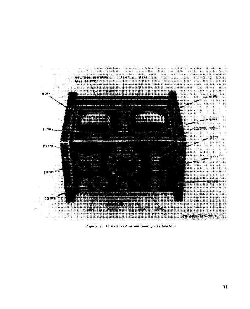
fig. 4
fig. 17
fig. 5
fig. 18
fig. 4
fig. 14
fig. 5
fig. 3
par. 18
fig. 4 and 18
fig. 17
fig. 18
par. 10
par. 18c
par. 10
fig. 4 and 18
fig. 18
fig. 17
par. 17e
fig. 5
fig. 4 and 6
fig. 4 and 6
par. 10
par. 19c
fig. 4 and 6
11. Localizing Troubles
a. General . Procedures are out l ined in the
f o l l o w i n g c h a r t f o r l o c a l i z i n g t r o u b l e s t o astage or part of the test set. Depending on the
n a t u r e o f t h e o p e r a t i o n a l s y m p t o m s , o n e o rmore of the localizing procedures will be nec-
essary. When use of the procedures results inlocalization of trouble to a particular stage orc ircuit , but not to a part icular part , re fer toparagraphs 12, 13, and 14. Figures 3 through7 show the location of parts in the control unit;figures 10, 12, 13 and 14 show the location ofparts in the rect i f ier unit . Figure 17 is theequipment schematic d iagram, f igure 18 the
c. Trouble-shooting Chart.
control unit wiring diagram, and figure 19 the
rectifier unit wiring diagram,
b. Use of Chart. T h e t r o u b l e s h o o t i n g c h a r t
supplements the equipment performance check
l i s t ( T M 1 1 - 6 6 2 5 - 2 7 3 - 1 2 ) . P e r f o r m t h e p r o -
cedures out l ined in the troubleshoot ing chart
(c b e l o w ) . I f n o o p e r a t i o n a l s y m p t o m s a r e
k n o w n , r e f e r t o t h e e q u i p m e n t p e r f o r m a n c e
c h e c k l i s t ( T M 1 1 - 6 6 2 5 - 2 7 3 - 1 2 ) .
Caution: If operational symptoms are not
known, or they indicate the possibility of short
circuits, make the continuity test (par. 10)
before applying power to the equipment.

9
fig. 14
fig. 10
fig. 12 par. 20
par. 24
par. 22
par. 23
fig. 6 and 18
fig. 6 and 18
fig. 18
fig. 18
fig. 18
fig. 6 and 18
fig. 13
fig. 19
fig. 5 and 18
fig. 4 and 18
fig. 5, 6, and 18
fig. 6
fig. 18
par. 18c
fig. 6 and 18
12. Checking Protective Circuits (2) Set up the tester controls for a posi-
a. Prechecking Procedure . B e f o r e c h e c k i n g t ive (+) output at 5 ,000 vo l ts .
the components o f the protect ive c i rcu i ts ( b b . Checking Procedure .
below) , per form the preoperat ional procedures Warning: After each check listed below,( p a r . 1 3 , T M 1 1 - 6 6 2 5 - 2 7 3 - 1 2 ) w i t h t h e f o l - turn voltage control T101 to 0, place circuitl owing except ions : breaker switch CB101 in the OFF position,
(1 ) Connect the ground cable d irect ly to lower the high-voltage caution plate againstearth ground instead of to the frame the output terminals, and allow the tester to

10
TM 6625-273-35-8
Figure 3.
11
Figure 4.
TM 6625-273-35-5
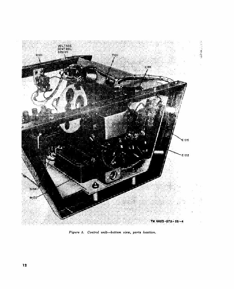
Figure 5.
12
TM 6625-273-35-4
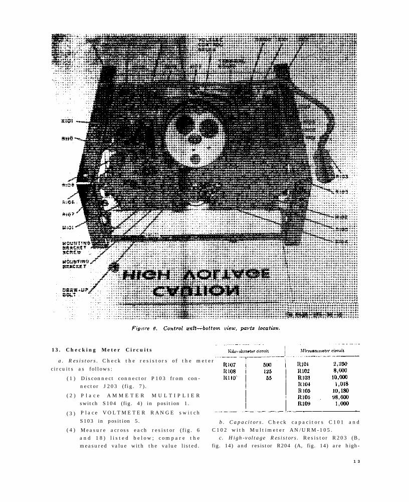
Figure 6.
TM 6625-273-35-10
13. Checking Meter Circuits
a. Res is tors . C h e c k t h e r e s i s t o r s o f t h e m e t e r
c ircuits as fo l lows:
( 1 )
( 2 )
( 3 )
( 4 )
Disconnect connector P103 f rom con-nector J203 ( f ig . 7 ) .
P l a c e A M M E T E R M U L T I P L I E Rswitch S104 (fig. 4) in position 1.
P l a c e V O L T M E T E R R A N G E s w i t c h
S103 in position 5.
Measure across each res is tor ( f ig . 6a n d 1 8 ) l i s t e d b e l o w ; c o m p a r e t h emeasured value with the value listed.
b. Capaci tors . C h e c k c a p a c i t o r s C 1 0 1 a n dC 1 0 2 w i t h M u l t i m e t e r A N / U R M - 1 0 5 .
c. High-voltage Resistors. Resistor R203 (B,fig. 14) and resistor R204 (A, fig. 14) are high-
1 3
fig. 12 and 19
fig. 14
fig. 12
fig. 19
vol tage meter res is tors o f 50 megohms each .To check resistors R203 and R204, follow thep r o c e d u r e s g i v e n i n p a r a g r a p h 1 0 , i t e m s 2eand f .
d . Meters . C h e c k k i l o v o l t m e t e r M 1 0 1 a n d
microammeter M102 as fo l lows:( 1 )
( 2 )
( 3 )
( 4 )
( 5 )
P e r f o r m t h e p r e o p e r a t i o n a l p r o c e -
dures listed in paragraph 12a exceptthat the output is adjusted for a posi-t ive (+) 500 vo l ts .
C o n n e c t M u l t i m e t e r A N / U R M - 1 0 5across the output of the tester.
P l a c e V O L T M E T E R R A N G E s w i t c h
S103 (fig. 4) in the 5 position.P l a c e A M M E T E R M U L T I P L I E Rswitch S104 in the 1 position.Turn the tester on and increase theo u t p u t u n t i l t h e A N / U R M - 1 0 5 ( ( 2
above) indicates 500 volts.(a) Kilovoltmeter M101 should indicate
.5 kilovolt.(b) Microammeter M102 should indicate
25 microamperes .
14. Checking Rectif ier Unit
The components of the high-voltage rectifierare immersed in an oil tank. To locate troublesin the rectifier, remove the unit from the oilt a n k ( p a r . 1 9 ) a n d i n s p e c t c o m p o n e n t s f o rloose connect ions , e v i d e n c e o f a r c i n g , a n d
cracked or loose rect i f i er tubes . Af ter inspec -t ion o f the rect i f ier uni t components i s com-pleted, check them as follows:
a. Transformers T201 and T202. The res is t -ance of the windings of transformers T201 andT202 are g iven in the fo l lowing table . Check
the resistance of each winding and compare themeter indication with the value given below.
b. Resistors. To check resistors R201, R202,
R205, and R206, follow the procedures given inparagraph 10, item 2g.
c. Capacitors. C h e c k c a p a c i t o r s C 2 0 1 a n dC 2 0 2 w i t h M u l t i m e t e r A N / U R M - 1 0 5 o r b ysubst i tut ion (par . 24) .
14

C H A P T E R 3
REPAIRS
15. General Parts Replacement Techniques
a. This chapter describes the disassembly,replacement, and reassembly of components ofInsulat ion Breakdown Test Set AN/GSM-6.
b. When major repair or replacement is nec-essary, follow the sequence of instructions givenuntil the defective part is reached. Do not at-
tempt to replace parts until they are completelyaccessible.
c. During disassembly, group the disassem-bled parts o f each unit and tag disconnected
wires to avo id confus ion and to fac i l i tate re -assembly.
d. Whenever the equipment has been disas-
sembled, examine each exposed part to see thatit is not bent, broken, worn, or dirty, and thatit shows no evidence of arcing.
Warning: Before attempting any repairson the equipment be sure that it has beencompletely discharged (TM 11-6625-273-12) .Dangerous voltage may be present and maycause severe injury or death.
16. Removal and Replacement of Control
unit -
a. Removal .
Loosen the camlock retainers (fig. 7)
a n d r e m o v e t h e e n d p a n e l s ( n o t
shown) f rom the contro l uni t f rames( f ig . 3 ) .
S e p a r a t e c o n n e c t o r P 1 0 3 f r o m c o n -nector J203 ( f ig . 7 ) ,
Remove the mounting screws, spacers,and mount ing nuts f rom the contro lunit f rames.
S e p a r a t e t h e c o n t r o l u n i t f r o m t h e
Clean the components o f the contro lunit with a dry, lint-free cloth.
Clean the contact surface o f vo l tagecontro l T101 ( f ig . 6 ) .Check all components for loose or bro-k e n c o n n a t i o n s , c o r r o s i o n , a n d e v i -dence of arcing; clean if necessary.Replace any worn or de fec t ive com-ponents .
c . Replacement .
( 1 )
( 2 )
( 3 )
( 4 )
( 5 )
( 6 )
Place the control unit on the rectifierunit ( f ig . 3 ) .
Al ine the mounting holes and securet h e m o u n t i n g s c r e w s , s p a c e r s , a n dmounting nuts in place.Place the end panels (not shown) ont h e c o n t r o l u n i t f r a m e s a n d s e c u r e
the camlock retainers (fig. 7).Insert connector P103 into connectorJ203.Lower the high-vol tage caut ion plate(fig. 3) and check to see that the metal
short ing bars touch output terminalsE201 and E202.If the shorting bars do not touch theoutput terminals , bend the short ingb a r s a s n e c e s s a r y u n t i l c o n t a c t i smade.
17. Removal and Replacement of VoltageControl
(fig. 8)
a. Removal .
( 1 )
( 2 )
( 3 )
( 4 )
Disconnect the wires from the termi-nal board.Loosen the setscrews and remove theknob .
R e m o v e t h e s c r e w s t h a t s e c u r e t h edial plate; remove the dial plate.Remove the screws that secure voltagecontro l T101 to the f ront panel ; re -move the voltage control from the rear
of the control unit (fig. 6).b.Cleaning and Inspection.
( 1 )
( 2 )
( 3 )
Clean al l components o f the vol tagecontrol with a dry, lint-free cloth.Sand the end o f the vo l tage contro lbrush (fig. 6) to obtain a flat contact.
Note. If the voltage control brush isbeing replaced, sand the contact end to ob-tain a flat contact.Inspect all wires and parts of the volt-age control; repair or replace as nec-essary .
c . Replacement .
( 1 ) P o s i t i o n t h e v o l t a g e c o n t r o l ( T 1 0 1 )against the control panel.
1 5
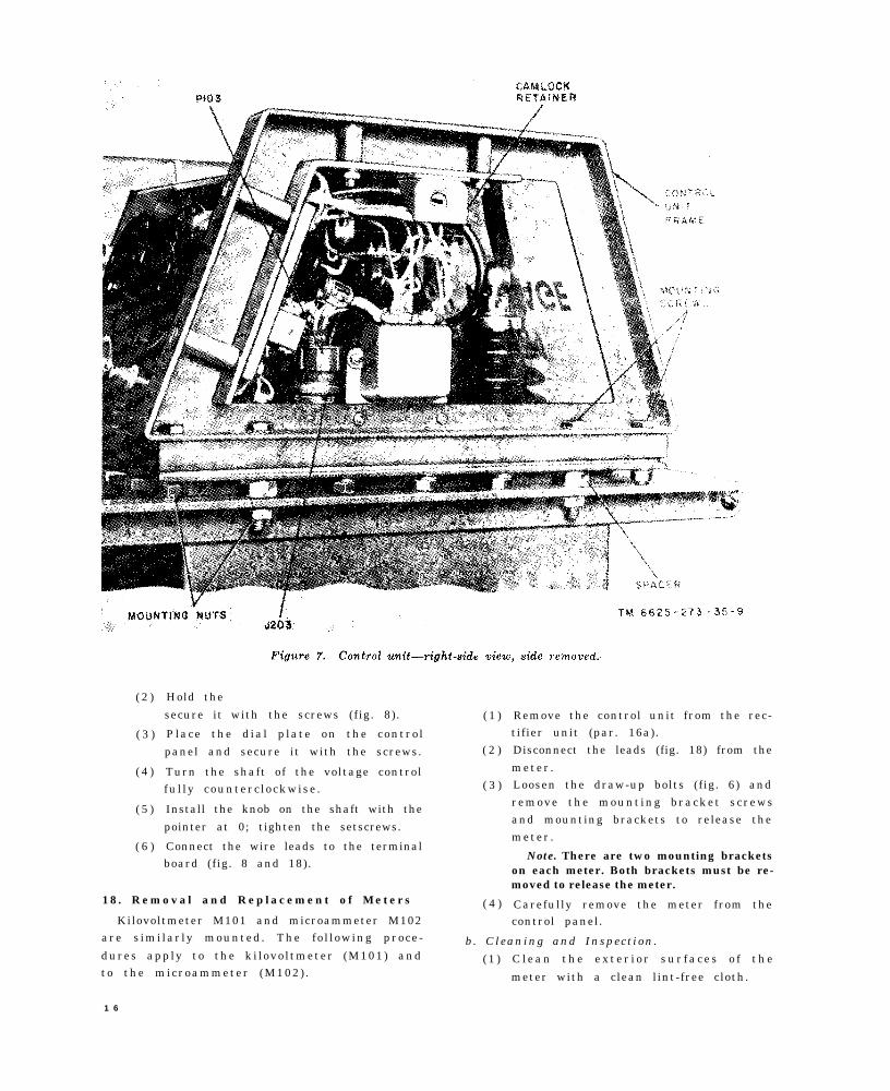
Figure 7.
TM 6625-273-35-9
( 2 )
( 3 )
( 4 )
( 5 )
( 6 )
Hold the
secure it with the screws (fig. 8). ( 1 )
Place the d ia l p late on the contro l
panel and secure it with the screws. ( 2 )
Turn the shaft of the voltage controlfu l ly counterc lockwise . ( 3 )
Install the knob on the shaft with the
pointer at 0; tighten the setscrews.
Connect the wire leads to the terminalboard (fig. 8 and 18).
18. Removal and Replacement of Meters ( 4 )Kilovoltmeter M101 and microammeter M102
Remove the control unit from the rec-tifier unit (par. 16a).Disconnect the leads (fig. 18) from the
meter .Loosen the draw-up bolts (fig. 6) andremove the mount ing bracket screwsand mounting brackets to release themeter .
Note. There are two mounting bracketson each meter. Both brackets must be re-moved to release the meter.
Carefully remove the meter from thecontrol panel.
are s imi lar ly mounted . The fo l lowing proce- b. Cleaning and Inspect ion .dures apply to the ki lovol tmeter (M101) and ( 1 ) C l e a n t h e e x t e r i o r s u r f a c e s o f t h eto the microammeter (M102) . meter with a clean lint-free cloth.
1 6

Figure 8.
TM 6625-273-35-9
( 2 ) Inspect the meter for a damaged or
missing pointer, broken dial glass, andoverall condition. If the meter is dam-
aged or otherwise defective, obtain areplacement meter .
c . Replacement .
( 1 ) P o s i t i o n t h e m e t e r i n t h e c o n t r o l
( 2 )
( 3 )
( 4 )
( 5 )
panel .Secure the meter mount ing bracketst o t h e m e t e r w i t h t h e m o u n t i n gbracket screws .Tighten the draw-up bol ts to secure
the meter to the contro l panel .
Connect the leads to the meter ( f ig .1 8 ) .Replace the control unit on the recti-f ier unit (par . 16c) .
1 9 . R e m o v a l a n d R e p l a c e m e n t o f H i g h -v o l t a g e R e c t i f i e r
C a u t i o n : D o n o t r e m o v e t h e h i g h - v o l t a g erect i f ier f rom the tank in humid atmosphere
or when the temperature o f the equipment i s
b e l o w t h e a m b i e n t t e m p e r a t u r e . - T h e h i g h -voltage rectifier is oil-immersed in a tank. Thet r a n s f o r m e r s a r e v a c u u m - i m p r e g n a t e d . B e -c a u s e o f t h e h i g h v o l t a g e s i n v o l v e d d u r i n g—o p e r a t i o n , a n y t r a c e o f m o i s t u r e m a y c a u s einternal breakdowns.
a. Removal .
( 1 )
( 2 )
( 3 )
( 4 )
( 5 )
Remove the control unit from the rec-t i f ier unit (par . 16a) .R e m o v e t h e t a n k m o u n t i n g s c r e w s
( f ig . 3 ) and the tank mounting nutsthat secure the top plate to the recti-fier unit tank.W o r k t h e t o p p l a t e l o o s e f r o m t h e
tank.L i f t t h e h i g h - v o l t a g e r e c t i f i e r a n d ,with the use o f wood b locks ( f ig . 9 ) ,prop it on the tank to drain.Remove the high-voltage rectifier fromt h e t a n k ( a f t e r d r a i n i n g ) a n d p l a c eit on a sturdy work bench.
1 7
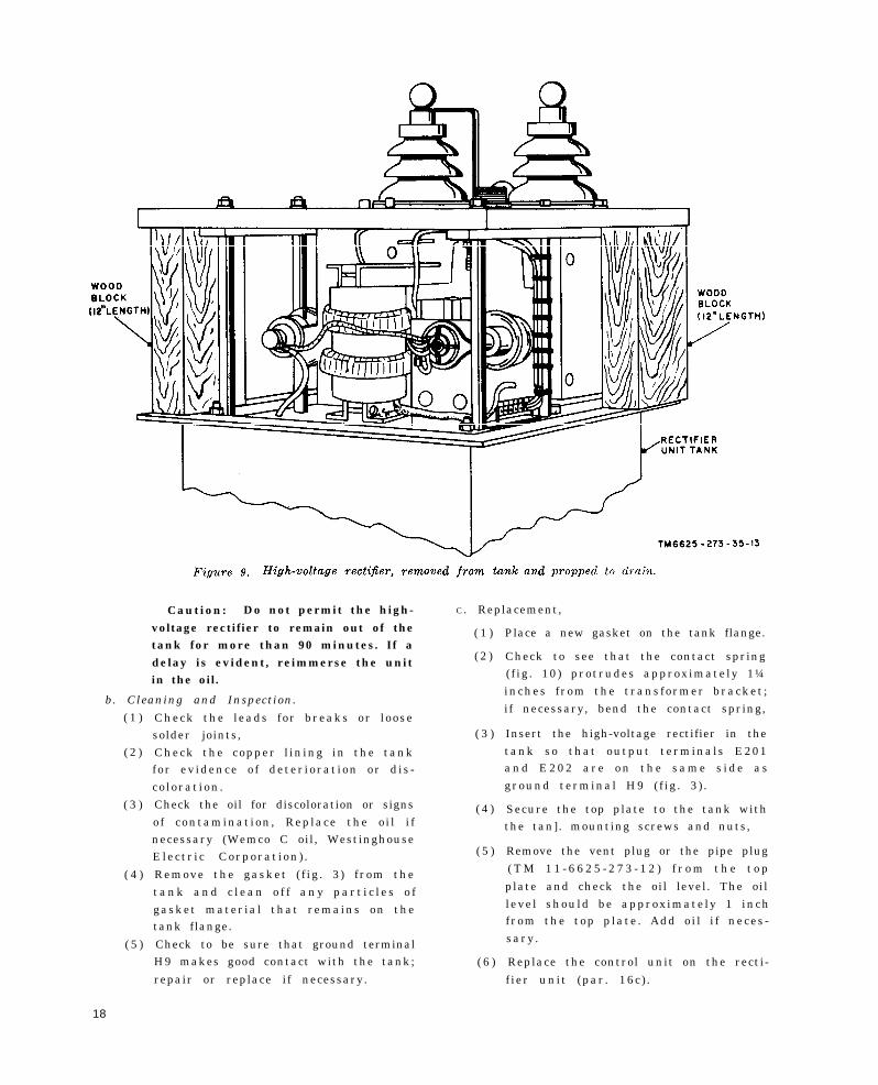
Figure 9.
TM6625-273-35-13
Caution: Do not permit the high- C . Replacement,
voltage rectifier to remain out of thetank for more than 90 minutes. If a
( 1 )
delay is evident, reimmerse the unit ( 2 )
in the oil.
b. Cleaning and Inspection.
( 1 )
( 2 )
( 3 )
( 4 )
( 5 )
18
Check the leads for breaks or loosesolder joints, ( 3 )
Check the copper l in ing in the tankfor ev idence o f deter iorat ion or d is -co lorat ion .Check the oil for discoloration or signs ( 4 )o f contaminat ion , Replace the o i l i fnecessary (Wemco C oil, WestinghouseElectr i c Corporat ion) . ( 5 )
Remove the gasket ( f ig . 3 ) f rom thet a n k a n d c l e a n o f f a n y p a r t i c l e s o fgasket material that remains on thetank flange.
Check to be sure that ground terminalH9 makes good contact with the tank; ( 6 )repair or replace if necessary.
Place a new gasket on the tank flange.
Check to see that the contact spring( f ig . 10) protrudes approximately 1¼inches f rom the transformer bracket ;if necessary, bend the contact spring,
Insert the high-voltage rectifier in thetank so that output terminals E201a n d E 2 0 2 a r e o n t h e s a m e s i d e a sground terminal H9 ( f ig . 3 ) .
Secure the top plate to the tank withthe tan]. mounting screws and nuts,
Remove the vent plug or the pipe plug( T M 1 1 - 6 6 2 5 - 2 7 3 - 1 2 ) f r o m t h e t o p
plate and check the oil level. The oilleve l should be approximately 1 inchfrom the top p late . Add o i l i f neces -sary .
Replace the control unit on the recti-
f ier unit (par . 16c) .
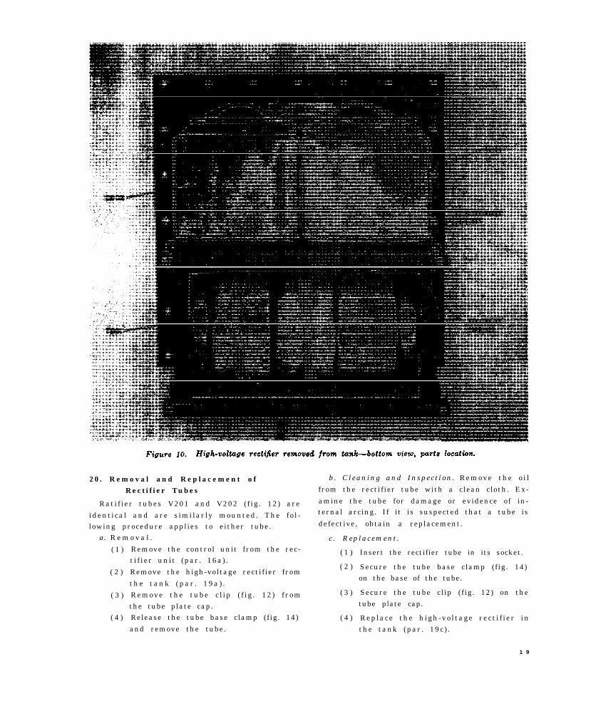
Figure 10.
TM6625-273-35-14
20. Removal and Replacement ofRectifier Tubes
Rati f ier tubes V201 and V202 ( f ig . 12) are
identical and are s imilar ly mounted. The fo l -lowing procedure applies to either tube.
a. R e m o v a l .
( 1 )
( 2 )
( 3 )
( 4 )
Remove the control unit from the rec-t i f ier unit (par . 16a) .
Remove the high-voltage rectifier from
t h e t a n k ( p a r . 1 9 a ) .Remove the tube c l ip ( f ig . 12) f romthe tube plate cap.Release the tube base clamp (fig. 14)
and remove the tube.
b. Cleaning and Inspect ion . Remove the o i l
from the rectifier tube with a clean cloth. Ex-
amine the tube for damage or evidence of in-ternal arcing. If it is suspected that a tube is
defective, obtain a replacement.
c . Replacement .
( 1 )
( 2 )
( 3 )
( 4 )
Insert the rectifier tube in its socket.
Secure the tube base clamp (fig. 14)on the base of the tube.
Secure the tube clip (fig. 12) on thetube plate cap.
Replace the h igh-vo l tage rect i f ier inthe tank (par . 19c ) .
1 9

Figure 11.
TM6625-273-35-16
(5) Replace the control unit on the recti-
fier unit (par. 16c).
21. Removal and Replacement of Output
Terminals
Output terminals E201 and E202 ( f ig . 11)are identical and are s imilar ly mounted. Thefollowing procedures apply to both output ter-
minals.
a. R e m o v a l .
( 1 )
( 2 )
( 3 )
( 4 )
( 5 )
( 6 )
Remove the control unit from the rec-
tifier unit (par. 16a),
R e m o v e t h e h i g h - v o l t a g e r e c t i f i e rfrom the tank (par. 19a).
Unsolder the terminal lead ( f ig . 12and 18) from the output terminal.
Loosen the jamnuts ( f ig . 11) on thepressure screws to decrease the ten-
sion on the output terminal.
Lift up on the retainer plate and re-move the reta iner spr ing ; l ower and
remove the retainer plate.
Lift the output terminal out of the top
plate.
Note. The guard ring is connected toguard terminal H10 (fig. 3) through thebalance strip (fig. 11). The balance stripis soldered to the guard ring, passes downthrough the hole in the top plate, and issoldered to the guard plate. If it becomesnecessary to replace the guard ring or gasket,the balance strip must be unsoldered fromthe guard plate.
b. Cleaning and Inspection.
(1) Clean all parts of the output terminal;dry thoroughly.
(2) Check the output terminal for crackedo r b r o k e n p o r c e l a i n a n d b r o k e n o r
loose components . Repair or replacewhen necessary.
c . Replacement .
( 1 )
( 2 )
( 3 )
2 0
I n s e r t t h e o u t p u t t e r m i n a l t h r o u g hthe guard ring, gasket, and top plate.
Place the retainer plate over the bot-tom end of the output terminal, withthe convex side of the retainer plate
toward the top plate.
I n s e r t t h e r e t a i n e r s p r i n g i n t h e
groove at the base of the output ter-
minal.
( 4 )
( 5 )
( 6 )
( 7 )
I n s e r t t h e p r e s s u r e s c r e w s t h r o u g hthe reta iner p late and t ighten themsufficiently to hold the output terminalin place. Secure the screws with the
j a m n u t s .
Solder the terminal lead (fig. 12 and19) to the output terminal.
Replace the h igh-vo l tage rect i f ier inthe tank (par. 19c).
Replace the control unit on the recti-
f ier unit (par , 16c) .
22. Removal and Replacement of
Transformer T201
a. Removal .
Note. Be sure to tag all leads or shields before theyare disconnected.
( 1 )
( 2 )
( 3 )
( 4 )
( 5 )
( 6 )
( 7 )
( 8 )
( 9 )
Remove the control unit from the rec-t i f ier unit (par . 16a) .R e m o v e t h e h i g h - v o l t a g e r e c t i f i e rfrom the tank (par . 19a) .
U n s o l d e r t h e p r i m a r y l e a d s ( T 2 0 1 )f r o m p i n s C a n d D o f t h e t e r m i n a l
b o a r d ( f i g . 1 2 a n d 1 9 ) ; r e m o v e t h eleads from the shield.D i s c o n n e c t t h e p r i m a r y l e a d s h i e l dfrom the point of connection.
Unsolder the secondary lead (T201)that i s connected to the tube c l ip o ftube V201.
U n s o l d e r t h e o t h e r s e c o n d a r y l e a d(T201) from the capacitor mountingf r a m e ( f i g . 1 3 ) .Disconnect the secondary lead shie ld(fig. 12) from the point of connection.
Remove the bolts, spacers, and associ-a t e d w a s h e r s a n d n u t s t h a t s e c u r etransformer T201 to the transformerp l a t e ; r e m o v e t h e t r a n s f o r m e r f r o m
the equipment.Remove the contact spr ing ( f ig . 10)from the bottom of the transformer
bracket .
b. Cleaning and Inspect ion . R e m o v e e x c e s s
o i l f rom the transformer to permit v isual in -spect ion . Check for ev idence o f overheat ing ,b r o k e n w i r e s , a n d d a m a g e d o u t e r w r a p p i n g .Replace if neceseary.
c . Replacement .
Caution: If a replacement transformer isto be installed in the equipment, do not removeit from the sealed container until it is readyfor installation. Prolonged exposure to airmay cause the transformer to break downduring operation.
( 1 )
( 2 )
Install the contact spring at the bot-tom o f the transformer bracket ( f ig .10). Check to be sure that the contacts p r i n g p r o t r u d e s a p p r o x i m a t e l y 1 ¼inches .
D r e s s t h e p r i m a r y l e a d s ( T 2 0 1 ) t othe side of the transformer facing theterminal board ( f ig . 12) .
( 3 )
( 4 )
( 5 )
( 6 )
( 7 )
( 8 )
( 9 )
Secure the transformer to the trans-former p late with the bo l ts , spacers ,
and associated washers and nuts.
R u n t h e p r i m a r y l e a d s ( T 2 0 1 )through the primary lead shield. Sol-der one lead to pin C on the terminal
board and the other lead to pin D onthe terminal board (fig. 12 and 19).Solder one secondary lead (T201) tothe tube clip of tube V201.
Connect the other secondary lead tothe capacitor mounting frame (fig. 13
a n d 1 9 ) .C o n n e c t t h e p r i m a r y l e a d s h i e l d(a(4) above) and the secondary lead
s h i e l d ( a ( 7 ) a b o v e ) t o t h e i r r e s p e c -
tive points of connection.Replace the h igh-vo l tage rect i f ier inthe tank (par. 19c).Replace the control unit on the recti-f ier unit (par . 16c) .
23. Removal and Replacement of
Transformer T202
a. Removal .
Note. Be sure to tag all leads or shields before theyare disconnected.
( 1 )
( 2 )
( 3 )
( 4 )
( 5 )
( 6 )
( 7 )
( 8 )
( 9 )
( 1 0 )
Remove the control unit from the rec-tifier unit (par. 16a).Remove the high-voltage rectifier unitfrom the tank (par . 19a) .Remove the rect i f ier tubes f rom thehigh-voltage rectifier (par. 20a).Unsolder the terminal leads from out-put terminals E201 and E202 (fig. 12a n d 1 9 ) .Unsolder the leads from pins A and B(not shown) of the terminal board.
Unsolder the leads that connect resis-tors R203 and R204 (fig. 14 and 19) tothe terminal board.
R e m o v e t h e l a c i n g f r o m t h e c a b l eleading to connector J203 (fig. 12).Remove the top plate bolts and raisethe top plate.Unsolder the secondary leads (T202)
from the tube sockets (fig. 12 and 19)and remove the lacing.U n s o l d e r t h e p r i m a r y l e a d s ( T 2 0 2 )f r o m p i n s A a n d B o f t h e t e r m i n a lboard, and remove the leads from theshield.
2 1

Figure 12.
TM 6625-273-35-7
( 1 1 )
( 1 2 )
( 1 3 )
( 1 4 )
( 1 5 )
2 2
Disconnect the pr imary lead (T202)shield from its point of connection.Unsolder the leadR203 (B, f ig . 14)E201 ( f ig . 19) .Unsolder the leadR204 (A, f ig . 14)E202 ( f ig . 19) .
connect ing res istorto output terminal
connect ing res istorto output terminal
U n s c r e w t h e t r a n s f o r m e r m o u n t i n g
bolts to release the transformer fromthe transformer plate (B, fig. 14).
Unscrew the screws (not shown) tore lease the res is tor mount ing p latesfrom the transformer .
b. Cleaning and Inspect ion . R e m o v e e x c e s s
o i l f rom the transformer to permit v isual in -
spect ion . Check for ev idence o f overheat ing ,
b r o k e n w i r e , and damaged outer wrapping .
Replace if necessary.
c . R e p l a c e m e n t
C a u t i o n : If a replacement transformer is
to be installed in the equipment, do not remove
it from the sealed container until it is ready
for installation. Prolonged exposure to air
may cause the transformer to break down
during operation.
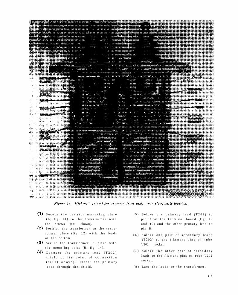
Figure 13.
TM 6625-273-35-6
S e c u r e t h e r e s i s t o r m o u n t i n g p l a t e ( 5 )(A, f ig . 14) to the transformer withthe screws (not shown).Position the transformer on the trans-former p late ( f ig . 12) with the leads ( 6 )at the bottom.
Secure the transformer in place withthe mounting bolts (B, fig. 14).
C o n n e c t t h e p r i m a r y l e a d ( T 2 0 2 ) ( 7 )
s h i e l d t o i t s p o i n t o f c o n n e c t i o n( a ( 1 1 ) a b o v e ) . I n s e r t t h e p r i m a r yleads through the shield. ( 8 )
S o l d e r o n e p r i m a r y l e a d ( T 2 0 2 ) t opin A o f the terminal board ( f ig . 12and 19) and the other primary lead topin B.
S o l d e r o n e p a i r o f s e c o n d a r y l e a d s(T202) to the f i lament pins on tubeV201 socket.
S o l d e r t h e o t h e r p a i r o f s e c o n d a r yleads to the filament pins on tube V202socket.
Lace the leads to the transformer.
2 3
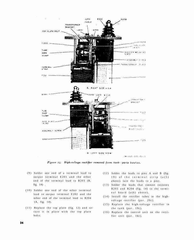
Figure 14.
24
TM 6625-273-35-15
( 9 )
( 1 0 )
( 1 1 )
Solder one end of a terminal lead to ( 1 2 )output terminal E201 and the otherend of the terminal lead to R203 (B,fig. 14) . ( 1 3 )
Solder one end of the other terminallead to output terminal E202 and theother end of the terminal lead to R204
( 1 4 )
(A, fig. 14).( 1 5 )
Replace the top plate (fig. 12) and se-cure i t in p lace with the top plate ( 1 6 )bolts.
Solder the leads to pins A and B (fig.1 9 ) o f t h e t e r m i n a l s t r i p ( a ( 5 )above); lace the leads to a post.
Solder the leads that connect resistorsR203 and R204 (fig. 14) to the termi-n a l b o a r d ( a ( 6 ) a b o v e ) .
Install the rectifier tubes in the high-vo l tage rect i f ier (par . 20c ) .
Replace the h igh-vo l tage rect i f ier inthe tank (par . 19c ) .
Replace the control unit on the recti-f ier unit (par . 16c) .
24. Removal and Replacement of High-
voltage Capacitors
Capacitors C201 and C202 (fig. 13) are iden-t i c a l a n d s i m i l a r l y m o u n t e d . T h e f o l l o w i n gprocedures apply to both capacitors.
a. Removal .
( 1 )
( 2 )
( 3 )
( 4 )
( 5 )
( 6 )
( 7 )
Remove the control unit from the rec-
tifier unit (par. 16a).R e m o v e t h e h i g h - v o l t a g e r e c t i f i e rfrom the tank (par . 19a) .
Remove the rect i f ier tubes f rom thehigh-vol tage rect i f ier unit (par . 20a) ,
Remove the assembly screws (fig. 14)and remove the side plate from the ca-
pac i tor mounting frame ( f ig . 13) .Remove the nut and washer from theterminal of the capacitor.
R e m o v e t h e s u p p o r t p l a t e n u t s a n dpermit the support plates to drop free.Careful ly l i f t the h igh-vo l tage rect i -fier and remove the capacitor.
b. Cleaning and Inspect ion . R e m o v e e x c e s s
oil from the capacitor to permit visual inspec-
tion. Check the capacitor for cracked or brokenporce la in deter iorat ion , and ev idence o f l eak-
age; replace if necessary.c . Replacement .
( l )
( 2 )
( 3 )
( 4 )
( 5 )
( 6 )
( 7 )
( 8 )
Place the capac i tor on the bench inposition for insertion in the high-volt-age rectifier.Lower the high-voltage rectifier over
the capacitor. Be sure that the lug ofthe resistor (R205 or R206) is posi-tioned on the capacitor terminal.
Pos i t ion the capac i tor support p latesa n d s e c u r e t h e m w i t h t h e s u p p o r t
plate nuts .R e p l a c e t h e w a s h e r a n d n u t o n t h e
capacitor terminal.Secure the side plate (fig. 13) in placewith the assembly screws.
Install the rectifier tubes in the high-voltage rectifier (par. 20c).Replace the h igh-vo l tage rect i f ier inthe tank (par . 19c ) .Replace the control unit on the recti-fier unit (par. 16c).
2 5

C H A P T E R 4
F I N A L T E S T I N G
25. Purpose of Final Testing
The tests out l ined in th is chapter are de-s igned to measure the performance capabi l i tyo f repaired equipment . Equipment that meets
the minimum standards stated in these testswi l l furnish sat is factory operat ion, equivalentto that of new equipment.
26. Test Equipment Required
In addition to the tools and test equipmentlisted in paragraph 9, the following items arerequired for final testing.
27. Preliminary Check
a. P e r f o r m t h e p r e o p e r a t i o n a l p r o c e d u r e s
(par . 12a) except that the output is adjustedfor a positive (+) 40,000 volts.
b. No corona format ion , f lashover , or leak-age current should be present.
c. S h u t d o w n t h e e q u i p m e n t ( T M 1 1 - 6 6 2 5 -2 7 3 - 1 2 ) .
2 8 . F i n a l T e s t s
a. Spark Gap E105 Setting.
( 1 )
( 2 )
( 3 )
( 4 )
2 6
Loosen the camlock reta iner and re -move the end panel.
Measure the gap in spark gap E105
( f ig . 5 ) . I t should measure between.0015 inch and .002 inch.
P l a c e A M M E T E R M U L T I P L I E Rswitch S104 (fig. 4) in position 1.M e a s u r e t h e r e s i s t a n c e o f t h e g a p .The resistance should be 112,000 ohms
±5 per cent.
(5) Replace the end panel and secure the
camlock retainer.
b . P r o t e c t i v e C i r c u i t . T o t e s t t h e c o m p o -nents of the protective circuit, follow the pro-
cedures given in paragraph 12.
c. Meter Circuit Test.
( 1 )
( 2 )
( 3 )
( 4 )
( 5 )( 6 )
( 7 )
( 8 )
Connect the high-voltage connector ofthe output cable to the positive termi-nal of milliammeter M1.
Connect the negative terminal of mil-liammeter M1 directly to ground ter-minal H9 (f ig. 3) .
C o n n e c t M u l t i m e t e r A N / U R M - 1 0 5between connector J102 ( f ig . 4 ) andground terminal H9 ( f ig . 3 ) ; set the
AN/URM-105 to i ts 10-vo l t dc range .
Set AMMETER MULTIPLIER switchS104 (fig. 4) to position 100.Raise the high-voltage caution plate.Start the tester and very s lowly a d -just vo l tage contro l T101 unt i l bothm i c r o a m m e t e r M 1 0 2 a n d m i l l i a m -m e t e r M 1 i n d i c a t e 5 , 0 0 0 m i c r o a m -peres (5 milliamperes on M1).
T h e A N / U R M - 1 0 5 s h o u l d i n d i c a t ebetween 4.8 and 5.2 volts.
Shut down the test set (TM 11-6625-273-12) and disconnect all cables andtest equipment.
d. Leakage with Positive Output.
( 1 )
( 2 )
( 3 )
( 4 )( 5 )
( 6 )
( 7 )
P l a c e A M M E T E R M U L T I P L I E Rswitch S104 (fig. 4) in position 1.Place VOLTMETER RANGE switchS103 in position 50.Place both polarity switches (S102a n d S 1 0 5 ) i n t h e p o s i t i v e ( + ) p o s i -tion.Raise the high-vo l tage caut ion p late .
Start the tester and adjust the outputto 40,000 volts.Microammeter M102 should indicateless than microampere .Shut down the test set (TM 11-6625-
2 7 3 - 1 2 )
e . L e a k a g e w i t h N e g a t i v e O u t p u t . F o l l o wthe procedures in d above, but set up the equip-ment for a negat ive ( - ) output .

f . Voltage Under Load with Positive Output.
( 1 ) C o n n e c t r e s i s t o r s R 1 a n d R 2 a n d
m i l l i a m m e t e r M 1 i n s e r i e s b e t w e e noutput terminal E201 and ground ter-minal H9. Be sure that the polarity ofmi l l iammeter M1 is correct . Set AM-
M E T E R M U L T I P L I E R s w i t c h S 1 0 4to the 100 position.
(2) Start the tester and adjust the outputfor 40,000 volts.
( 3 ) M i c r o a m m e t e r M 1 0 2 a n d m i l l i a m -m e t e r M 1 s h o u l d b o t h i n d i c a t e b e -tween 980 and 1,020 microampere (.9to 1 mi l l iampere on M1) .
( 4 ) T h e s e t t i n g o f v o l t a g e c o n t r o l T 1 0 1
should be approximately 120.(5) Shut down the test set and disconnect
the test equipment.
g . Vol tage Under Load wi th Negat ive Out -
put . Fol low the procedures g iven in e a b o v e ,
but set up the equipment for a negat ive ( - )output . Be sure that the polar i ty o f mi l l iam-
meter M1 is correct.h . O n e H o u r L e a k a g e T e s t w i t h P o s i t i v e
o u t p u t .
( 1 ) P l a c e A M M E T E R M U L T I P L I E Rswitch S104 (fig. 4) in position 1.
(2) Start the tester and adjust the outputfor 40,000 volts.
(3 ) Permit the equipment to operate for1 hour.
(4) At the end of the hour, note the indi-
c a t i o n o n m i c r o a m m e t e r M 1 0 2 . T h ei n d i c a t i o n s h o u l d b e l e s s t h a n . 5microampere .
(5) Shut down the equipment.i. One Hour Leakage Test with Negative
O u t p u t . F o l l o w t h e p r o c e d u r e s g i v e n i n h
above, but set up the equipment for a negative( - ) o u t p u t .
2 7
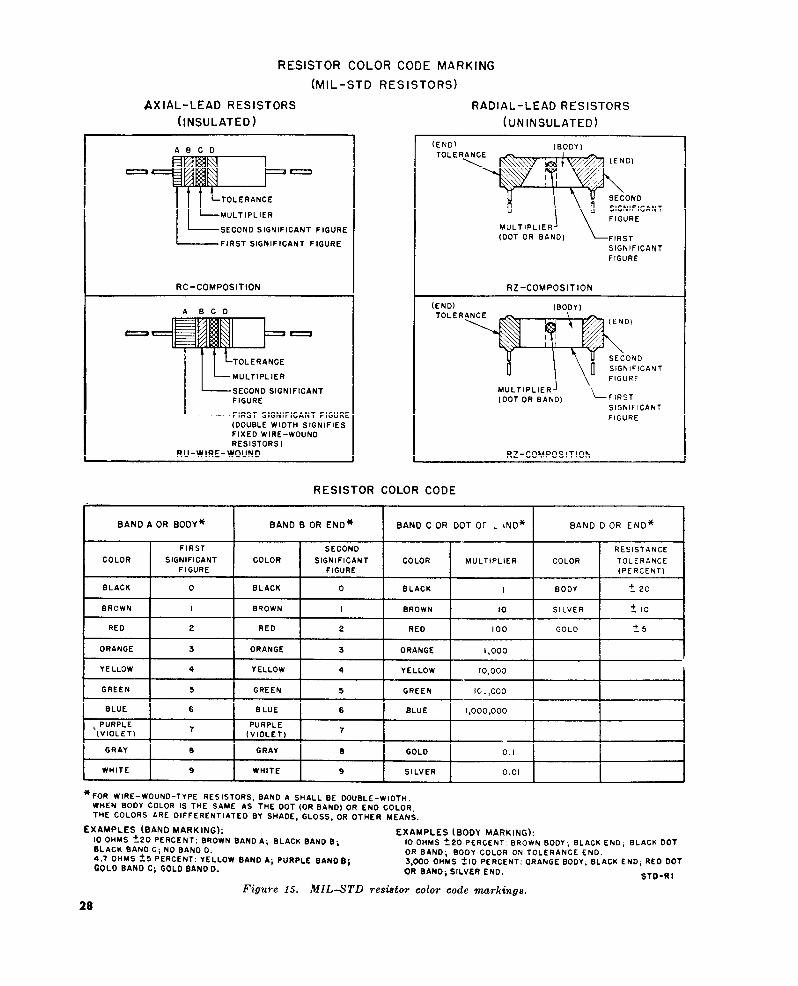
Figure 15.
28

Figure 16.29
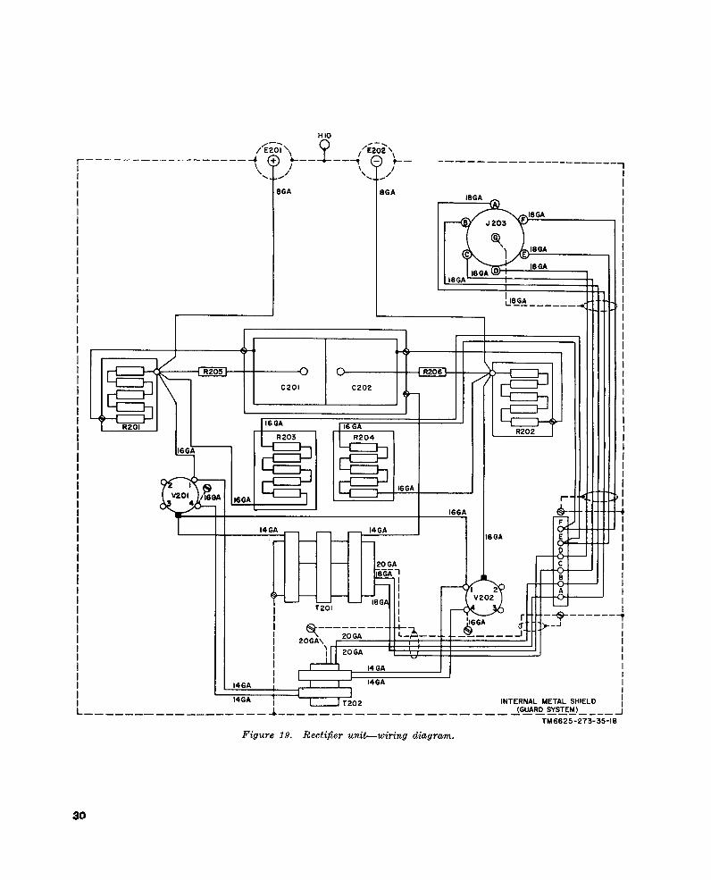
Figure 19.
30
TM6625-273-35-18
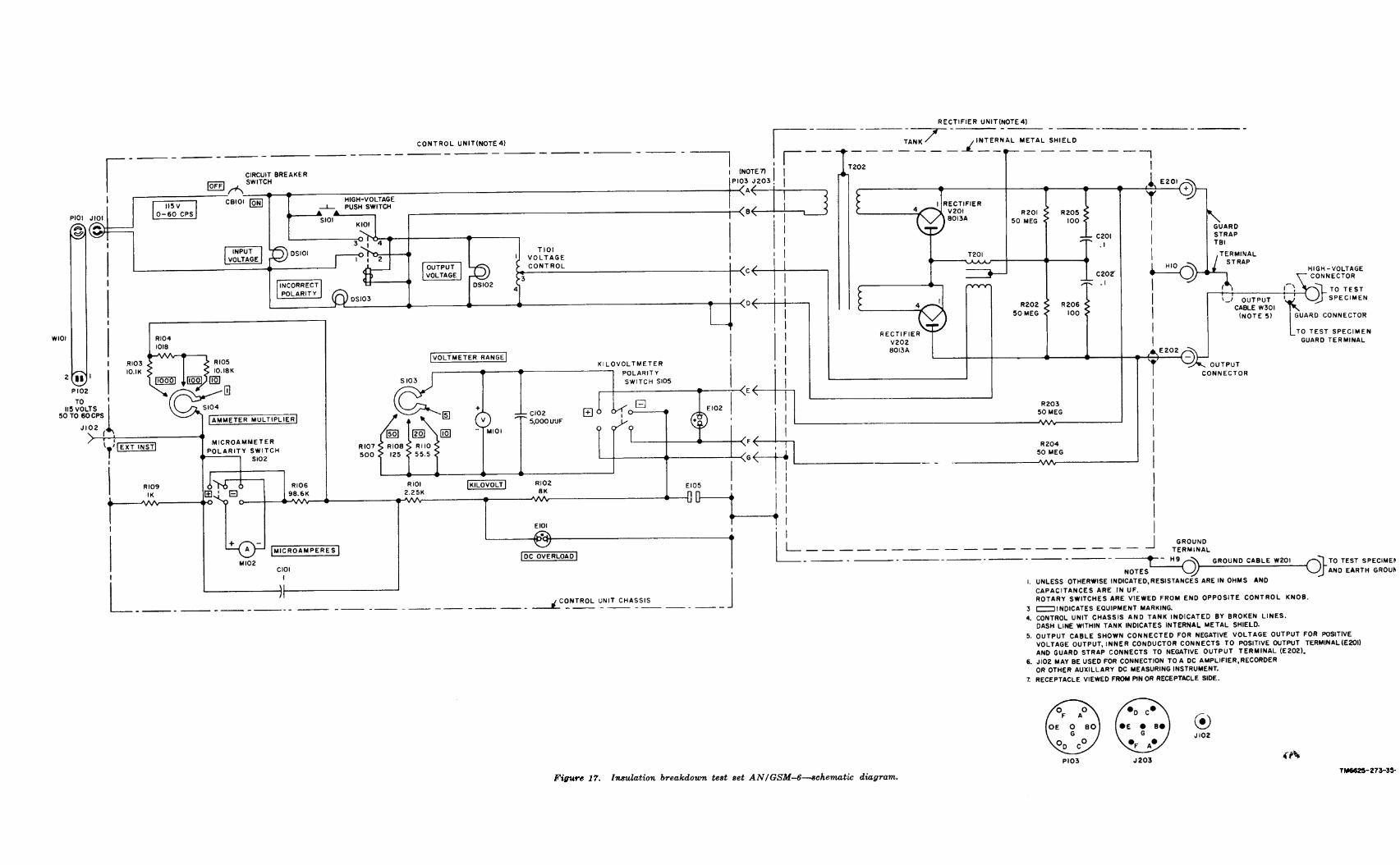
Figure 17.
TM6625-273-35-2
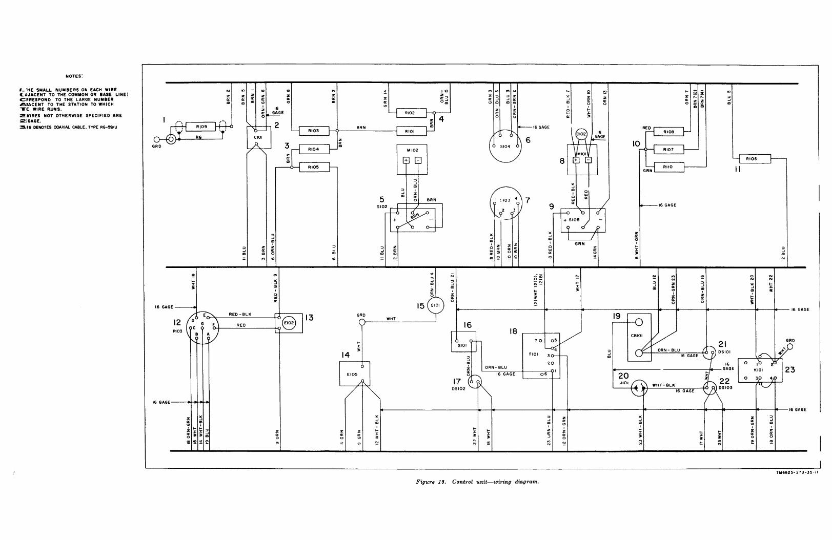
Figure 18.
TM6625-273-35-11

Off ic ia l :R. V. LEE,
Major General , Uni ted States Army,
T h e A d j u t a n t G e n e r a l .
Distribution:Active Army:
USASA (2)CNGB (1)Technical Stf, DA (1) except
CSigO (30)Technical Stf Bd (1)USCONARC (5)USA Arty Bd (1)USA Armor Bd (1)USA Armor Bd Test Sec (1)USA Inf Bd (1)USA Air Def Bd (1)USA Air Def Bd Test Sec (1)USA Abn & Elct Bd (1)USA Avn Bd (1)USA Arctic Test Bd (1)USARADCOM (2)USARADCOM Rgn (2)OS Maj Comd (5)OS Base Comd (5)Log Comd (5)MDW (1)Armies (5) except First US Army (7)Corps (2)Div (2)USATC (2)Fld Comd, Def Atomic Spt Agcy (5)Yuma Test Sta (2)USA Elct PG (1)Svc Colleges (5)Br Svc Sch (5) except USASCS (25)Gen Depot (2)Sig Sec Gen Depot (12)Sig Depots (19)AFIP (1)
NG: State AG (3).
USAR: None.
For exp~anation of abbreviations used, see AR 320-50.
L. L. LEMNITZER,General , Uni ted States Army,
Chie f o f Staf f .
WRAMC (1)AMS (1)Engr Maint Cen (1)USA Comm Agcy (2)USA Sig Comm Engr Agcy (1)USA Sig Eqp Spt Agsy (2)USA Sig Msl Spt Agcy (18)Trans Terminal Comd (1)Army Terminals (1)Port of Emb (OS) (2)OS Sup Agcy (2)Sig Fld Maint Shops (3)Sig Lab (5)Mil Dist (1)USA Corps (Res) (1)Sectors, USA Corps (Res) (1)USASSA (15)Midwestern Rgn Ofc (USASSA) (1)JBUSMC (2)USA Sig Pubs Agcy (8)Army Pictorial Cen (2)USA Ord Msl Comd (3)Units org under fol TOE:
11-7 (2)11-16 (2)11-57 (2)11-97 (2)11-117 (2)11-155 (2)11-500 AA-EE (2)11-587 (2)11-592 (2)11-597 (2)
3 1


This fine document...
Was brought to you by me:
Liberated Manuals -- free army and government manuals
Why do I do it? I am tired of sleazy CD-ROM sellers, who take publicly available information, slap “watermarks” and other junk on it, and sell it. Those masters of search engine manipulation make sure that their sites that sell free information, come up first in search engines. They did not create it... They did not even scan it... Why should they get your money? Why are not letting you give those free manuals to your friends?
I am setting this document FREE. This document was made by the US Government and is NOT protected by Copyright. Feel free to share, republish, sell and so on.
I am not asking you for donations, fees or handouts. If you can, please provide a link to liberatedmanuals.com, so that free manuals come up first in search engines:
<A HREF=http://www.liberatedmanuals.com/>Free Military and Government Manuals</A>
– SincerelyIgor Chudovhttp://igor.chudov.com/
– Chicago Machinery Movers