prkreddy - gnits.ac.inrotor earth fault protection the rotor of the generator is normally unearthed,...
TRANSCRIPT
PRKREDDY.GNITS
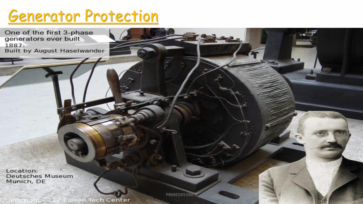
Generator Protection
PRKREDDY.GNITS

PRKREDDY.GNITS

PRKREDDY.GNITS

PRKREDDY.GNITS

PRKREDDY.GNITS

PRKREDDY.GNITS
PRKREDDY.GNITS

PRKREDDY.GNITS

PRKREDDY.GNITS
PRKREDDY.GNITS

Stator Protection:1. Percentage differential protection2. Percentage against stator inter-turn faults3. Stator over heating protection
Rotor protection:1. Field ground fault protection2. Loss of excitation protection3. Protection against rotor over heating
Miscellaneous:1. Over voltage protection2. Over speed protection3. Protection against motoring4. Protection against Vibration5. Bearing over heating protection6. Protection against auxiliary failure7. Protection against Voltage regulator failure
PRKREDDY.GNITS

Differential protection for generators:
Used for protection against phase to earth and phase to phase fault
Currents at two ends are compared.
Under normal conditions, currents will be same.
During fault current will be different
This difference of current is made to flow through relay operating coils.
This type of protection is called the merz price circulating current system.
PRKREDDY.GNITS

Limitations of this method:
The earth fault is limited by the resistance of the neural earthing.
Fault occurs near the neutral point, causes a small current to flow through the operating coil
Thus current is not sufficient to trip the circuit breaker.
By this scheme, only 80 to 85% of stator winding protected.
If the relays with low settings are used then it will not provide desire stability.
This difficulty is overcome by using the modified differential protection.
PRKREDDY.GNITS

Modified differential protection:
setting of the earth faults can be reduced without any effect on the stability.
Two relays are used for the phase to phase fault andone relay is used for the protection of earth fault.
The star connected circuit is symmetrical in termsof impedance.
Fault current occurs due to the phase to phase fault,it cancels at the star point due to the equalimpedance.
Thus it is possible to operate with the sensitiveearth fault relays.
PRKREDDY.GNITS

With the differential protection any difference in theaccuracy of the CTs the mal-operation of the relay willoccurs.
Biased circulating current protection can automaticallyincrease the relay setting in proportion to the faultcurrent.
By suitable proportioning of the ratio of the relayrestraining coil to the relay operating coil any biased canbe achieved.
Biased circulating current protection (percentage differential relay protection):
Advantages of this method:a) does not require the CTs with balancing features.b) permit the low fault setting of the relay, thus protects the greater % of the stator winding.
Any phase to phase or phase to earth fault occurs,differences in the secondary current of the two CTs. currentflows through the operating coil and make the circuit breakerto trip.
PRKREDDY.GNITS

Self balance protection system:
Employed for earth fault and phase to phase fault.
Under normal conditions, current in the two leads of thecable in the same direction and no magnetization occurs inthe ring type CTs.
When the earth fault occurs, the fault current occursonly once through the CTs and thus magnetic fluxinduced, induces the emf in the relay circuit causes thecircuit breaker to trip.
This is very sensitive type earth fault protection but it alsohave some limitations:
a) a different design of the cable lead is required in thisscheme.
b) large electromagnetic forces are develop in the CT ringunder the condition of heavy short circuit.
PRKREDDY.GNITS

For protection of the lead cable from the circuitbreaker to stator terminal the ring CTs are to be placednear the circuit breaker which is again quitecumbersome.
This difficulty can be overcome by providing a metallicsheath around the cable (but insulated from it) andearthing it in a manner illustrated in Fig.
In case the lead punctures anywhere, there will be flowof current through the sheet, as illustrated in the Fig.and relay will be energized resulting in tripping of thecircuit breaker.
PRKREDDY.GNITS

Stator ground (Balanced- Earth) fault protection:
In small size generators, the neutral ends connectedinternally to a single terminal.
Under such conditions, it is not possible to use thecirculating current protection because neutral end isnot accessible
protection is provided against earth faults only byusing balanced earth-fault protection scheme.
Such scheme does not provide protection againstphase-to-phase faults until and unless they developinto earth faults, as most of them do.
protection scheme is often called restricted earth fault protection scheme.
PRKREDDY.GNITS

This protection is provided in large generatorsas an additional protection scheme.
Under normal working conditions, current flowingin the secondary of neutral CT is zero. Thus therelay remains de-energized.
Internal earth fault, fault current causes CTsecondary current flows through the relay, tripsthe circuit breaker.
External earth fault, sum of the currents at theterminals of the generator is equal to thecurrent in the neutral connection, so no currentflows through the relay operating coil.
However, scheme has a drawback. In case the earth fault occurs nearer the neutral terminal or whengrounding of neutral is through a resistance or through a distributing transformer, the fault current may beso low that the secondary current of the CT becomes lower than the pick-up current of the relay. The relaythus remains inoperative and the fault continues to persist in the generator winding which is highlyundesirable.
PRKREDDY.GNITS

Stator inter turn fault protection: Differential protection for stator does not provide protectionagainst the inter-turn faults on the same phase winding of thestator.
The coils of the modern turbo generator are single- turn , sothere is no need to provide inter –turn fault protection for theturbo generator.But the inter turn protection is necessary for the multi turngenerator like hydro electric generator. Some times statorwindings are duplicated to carry heavy current. In this casestator winding have two different paths.
In this type of protection primaries of the CTs are inserted in theparallel paths and secondary's are inter connected.Under normal condition current through the two parallel paths of the stator winding will be sameand no current flowing through the relay operating coil.Under inter turn fault, current flowing through the two parallel path will be different and thisdifference in current flowing through the operating coil and thus causes the circuit breaker totrip and disconnect the faulty section. This type of protection is very sensitive.
PRKREDDY.GNITS

Stator over heating protection:
Stator over heating is caused due to the overloads andfailure in cooling system.
It is very difficult to detect the over heating due to theshort circuiting of the lamination before any serious damageis caused.Temperature rise depend upon I^2Rt and also on thecooling.
To protect the stator against over heating, embed RTD orthermocouples are used in the slots below the stator coils.
These detectors are located on the different places in thewindings so that to detect the temperature throughout thestator.Detectors which provide the indication of temperaturechange are arranged to operate the temperature relay tosound an alarm.
PRKREDDY.GNITS

Stator Protection:1. Percentage differential protection2. Percentage against stator inter-turn faults3. Stator over heating protection
Rotor protection:1. Field ground fault protection2. Loss of excitation protection3. Protection against rotor over heating
Miscellaneous:1. Over voltage protection2. Over speed protection3. Protection against motoring4. Protection against Vibration5. Bearing over heating protection6. Protection against auxiliary failure
PRKREDDY.GNITS

Over voltage protection:
Over voltage due to increase in the speed of the prime mover due to sudden lossof load.
Overvoltage doesn't occur in the turbo generator because of sensitive speedcontrol governors.
But the over voltage protection is required for the hydro generator or gasturbine generators.
The over voltage protection is provided by two over voltage relays. one is theinstantaneous relays which is set to pick up at 130 to 150% of the rated voltageand another unit is IDMT which is set to pick up at 110% of rated voltage.
Over voltage may occur due to the defective voltage regulator and due to manualcontrol errors. PRKREDDY.GNITS

Under voltage protection:
If more than one generators supply the load and due to some reason onegenerator is suddenly trip, then another generators try to supply the load.
Each of these generators will experience a sudden increase in current andthus decreases the terminal voltage.
Automatic voltage regulator connected to the system try to restore thevoltage.
And under voltage relay type-27 is also used for the under voltageprotection.
PRKREDDY.GNITS

Over speed protection
Basically, over-speed control is part of the turbine control system.
Most large steam turbine controls have two or three separate speed controlunits, with one of these being strictly a mechanical centrifugal device that willclose the turbine control valves even if electrical power is lost to the controlsthat require electric input.
Over-speed protection must be selective and must not shut the unit down dueto a temporary loss of load, even if the cause is serious short circuit.
Short circuits anywhere near a generator will collapse the voltage and thegenerator experiences a loss of load. Since the turbine power is unchanged, theturbine-generator unit will over-speed until the governor throttles the turbineinput back. Faults are usually temporary, however, and there is no need to shutthe unit down unless the fault is on the generator or GSU transformer.
PRKREDDY.GNITS

Generator Motoring
If the mechanical input to the prime mover is removed while the generatoris in service, then rotors mmf wave will tend to drive the rotor, just like aninduction motor.
This is dangerous to both steam and hydro turbine.
In steam turbines, it may lead to overheating while in hydro turbine itwould cause cavitation of the turbine blades.
The motoring of generator can be detected by reverse power flow relayshaving sensitivity of 0.5% of rated power output with time delay ofapproximate 2 seconds.
PRKREDDY.GNITS

PROTECTION AGAINST VIBRATION
Protective-relaying practices and equipment used for “Protection against RotorOverheating because of Unbalanced Three-Phase Stator Currents” and “FieldGround-Fault Protection” prevent or minimize vibration under thosecircumstances.
If the vibration-detecting equipment is used, it will provide protection againstvibration also results from a mechanical failure or abnormality.
For a steam turbine, it is the general practice to provide vibration recordersthat can also be used if desired to control an alarm or to trip. However, it is notthe general practice to trip.
PRKREDDY.GNITS

BEARING-OVERHEATING PROTECTION
Bearing overheating can be detected by a relay actuated by a thermometer-typebulb inserted in a hole in the bearing, or by a resistance-temperature-detectorrelay, such as that described for stator-overheating protection, with thedetector embedded in the bearing.
Or, where lubricating oil is circulated through the bearing under pressure, thetemperature of the oil may be monitored if the system has provision for givingan alarm if the oil stops flowing.
PRKREDDY.GNITS
STATION AUXILIARY PROTECTION
It deserve higher-quality protective equipment.
At the same time, “essential” auxiliaries are kept in service under manualsupervision during overload conditions that would ordinarily call fortripping.
For large generating stations, protection against loss of vacuum, loss ofboiler pressure and failure of induced draught fans are provided.
PRKREDDY.GNITS

ROTOR EARTH FAULT PROTECTION
The rotor of the generator is normally unearthed, single fault due to insulation breakdown willnot rise the fault current., but if the fault occurs, continues then it will damage the field windingof the generator.
When one earth fault occurs in the rotor, it is not necessary system is completely trip,only the relay indicates that the fault has occurred.So generator should be taken out of service at leisure.
Three types of rotor earth fault protection scheme used.1.Potentiometer method2.AC injection method3.DC injection method
PRKREDDY.GNITS

ROTOR EARTH FAULT PROTECTION BY USING HIGH RESISTANCE
A high resistance is connected across the field winding ofthe rotor. The midpoint of the resistor is grounded througha sensitive relay.
Any earth fault in the field winding the voltage appearsacross the relay due to potentiometer action of the resistor.
But the fault for rotor center point could not detect.
This difficulty can be minimized by using another tap on theresistor somewhere else from the center of the resistor viaa push button. If this push button is pressed, the center tapis shift and the voltage will appear across the relay even inthe event of central arc fault occurs on the field winding.
PRKREDDY.GNITS

AC INJECTION METHODS FOR ROTOR EARTH FAULT PROTECTION
In this method, alternating current is injected into the field windingcircuit and ground along with a sensitive overvoltage relay anda current limiting capacitor. A single earth fault in the rotor willcomplete the circuit comprises the alternating current source,sensitive relay and earth fault. Thus, the earth fault is sensed bythe relay.
The major disadvantage of such type of system is the leakagecurrent that flows through the capacitor. This currentunbalanced the magnetic field and increase the stress on themagnetic bearing.
Another disadvantage of alternating current is that the relaycannot pick up the current that normally flow through thecapacitance to the ground. Thus, the care must be taken to avoidresonance between the capacitance and the relay inductance.
PRKREDDY.GNITS

The problem of the AC injection system can beovercome by using the DC injection method.
This method is simple and has no problem ofleakage currents.
The one terminal of the sensitive relay isconnected to the exciter, and the other terminalis connected to the negative terminal of the DCsource.
The positive terminal of the DC source isgrounded. When the earth fault occurs, the faultcurrent will complete the circuit path, and thefault is sensed by the relay.
DC INJECTION METHODS FOR ROTOR EARTH FAULT PROTECTION
PRKREDDY.GNITS

Loss of Excitation Protection of Alternator
Failure of excitation makes the generator run at a speed above the synchronous speed.
The generator or alternator becomes an inductiongenerator which draws magnetizing current from thesystem.Although this situation does not create any problemin the system immediately but over loading of thestator and overheating of the rotor due tocontinuous operation of the machine in this modemay create problems in the system in long-run.
There are mainly two schemes available forprotection against loss of field or excitation of agenerator
PRKREDDY.GNITS

For larger machines, it is recommended to tripthe machine after a certain prescribed delay inpresence of swing condition resulting from loss offield.
In addition to that there must be subsequentload shedding to maintain stability of the system.In this scheme of protection, an automaticimposition of load shedding to the system is alsoinherently required if the field is not restoredwithin the described time delay.
The scheme comprises an offset mho relay, andan instantaneous under voltage relay.
system voltage is the main indication of system stability. Therefore the offset mho relay isarranged to shut the machine down instantaneously when operation of generator is accompaniedby a system voltage collapse. The drop in system voltage is detected by an under voltage relaywhich is set to approximately 70 % of normal rated system voltage. The offset mho relay isarranged to initiate load shedding to the system up to a safe value and then to initiate a mastertripping relay after a predetermined time.
PRKREDDY.GNITS

Rotor Temperature Alarm:-
This kind of protection is only provided in case oflarge generators.
It gives the level of temperature.
In it resistance is measured by comparing voltageand current by a double actuating quantity movingcoil relay.
The operating coil being used as voltage coil andrestraining coil used as current coil.
The relay measure the ratio of voltage andcurrent because resistance gives the measure ofrotor temperature.
PRKREDDY.GNITS

During unbalanced, negative phase sequence currentsproduce a rotating magnetic field at synchronous speed atopposite direction to rotor field.Hence relative speed becomes double the synchronousspeed.Thus double frequency currents cause sever heating of therotor and can cause damage to the rotor.The unbalanced stator currents cause sever vibration andheating of stator.
The negative phase sequence filter along with theovercurrent relay provides the necessary protection againstthe unbalanced loads.
% S = (In/I) x 100Where %S = Percentage asymmetry
In = Negative sequence currentI = Rated current
Protection against Rotor over heating because of unbalanced stator currents
PRKREDDY.GNITS

Under and Over voltage protection:
Over Voltage Protection:Over voltage occurs because of the increase in the speed of the prime mover due to suddenloss in the load on the generator.Generator over voltage does not occur in the turbo generator because the control governors ofthe turbo generators are very sensitive to the speed variation. But the over voltage protectionis required for the hydro generator or gas turbine generators.The over voltage protection is provided by two over voltage relays have two units — one isthe instantaneous relays which is set to pick up at 130 to 150% of the rated voltage andanother unit is IDMT which is set to pick up at 110% of rated voltage. Over voltage may occurdue to the defective voltage regulator and also due to manual control errors.
Under Voltage Protection:If more than one generators supply the load and due to some reason one generator is suddenlytrip, then another generators try to supply the load. Each of these generators will experiencea sudden increase in current and thus decreases the terminal voltage. Automatic voltageregulator connected to the system try to restore the voltage. And under voltage relay type-27is also used for the under voltage protection.
PRKREDDY.GNITS

Over speed protection
Basically, over-speed control is part of the turbine control system. Mostlarge steam turbine controls have two or three separate speed control units,with one of these being strictly a mechanical centrifugal device that willclose the turbine control valves even if electrical power is lost to thecontrols that require electric input.
Over-speed protection must be selective and must not shut the unit downdue to a temporary loss of load, even if the cause is serious, for example, ashort circuit. Short circuits anywhere near a generator will collapse thevoltage and the generator experiences a loss of load. Since the turbinepower is unchanged, the turbine-generator unit will over-speed until thegovernor throttles the turbine input back. Faults are usually temporary,however, and there is no need to shut the unit down unless the fault is on thegenerator or GSU transformer.
PRKREDDY.GNITS

Generator Motoring
If the mechanical input to the prime mover is removed while the generator is in service,then rotors mmf wave will tend to drive the rotor, just like an induction motor.
This is dangerous to both steam and hydro turbine.
In steam turbines, it may lead to overheating while in hydro turbine it would causecavitation of the turbine blades.
The motoring of generator can be detected by reverse power flow relays havingsensitivity of 0.5% of rated power output with time delay of approximate 2 seconds.
PRKREDDY.GNITS

PROTECTION AGAINST VIBRATION
Protective-relaying practices and equipment that are described under theheadings “Protection against Rotor Overheating because of Unbalanced Three-Phase Stator Currents” and “Field Ground-Fault Protection” prevent orminimize vibration under those circumstances.
If the vibration-detecting equipment recommended under the latter heading isused, it will also provide protection if vibration results from a mechanicalfailure or abnormality.
For a steam turbine, it is the general practice to provide vibration recordersthat can also be used if desired to control an alarm or to trip. However, it is notthe general practice to trip.
PRKREDDY.GNITS

BEARING-OVERHEATING PROTECTION
Bearing overheating can be detected by a relay actuated by a thermometer-typebulb inserted in a hole in the bearing, or by a resistance-temperature-detectorrelay, such as that described for stator-overheating protection, with the detectorembedded in the bearing.
Or, where lubricating oil is circulated through the bearing under pressure, thetemperature of the oil may be monitored if the system has provision for giving analarm if the oil stops flowing.
PRKREDDY.GNITS

STATION AUXILIARY PROTECTIONPower-plant auxiliaries are treated somewhat differently from similarequipment used elsewhere.
It is generally felt that they deserve higher-quality protective equipment. Atthe same time, however, certain so-called “essential” auxiliaries are kept inservice under manual supervision during overload conditions that wouldordinarily call for tripping.
45,46 Reference 46 stresses the importance of keeping auxiliary motorsrunning during system disturbances, and describes techniques foraccomplishing this.
Reference 47 is a collection of several papers on the effect of reduced voltageand frequency on power-plant capabilities. The protection of station auxiliarieswill be treated in more detail where the protection of motors, transformers,and busses is described.
PRKREDDY.GNITS

Protection of Lines or Feeder
Requirements of Transmission line
1.During fault, only CB closest to the point should trip.
2.If the CB closest to the fault fails to trip, CB next should trip as back up.
3.The operating time of relay associated with protection of line should be as minimum as possible in order to prevent unnecessary tripping of circuit breakers associated with other healthy parts of power system.
The main methods of transmission line protection are –
1.Time graded over current protection.
2.Differential protection.
3.Distance protection.
PRKREDDY.GNITS

Time Graded Over Current Protection
Line Protection of Radial Feeder
Line Protection by Definite Time Relay
In radial feeder, the power flows in one direction only, which is from source to load. This type of feeders can easily be protected by using either definite time relays or inverse time relays.
PRKREDDY.GNITS

Line Protection by Inverse Relay
In inverse relay the time of operation is inversely proportional to fault current.
Although, the time setting of relay nearest to the source is maximum but still it will trip in shorter period if major fault occurs near the source, as the time of operation of relay is inversely proportional to faulty current.
PRKREDDY.GNITS

Line Protection of Parallel Feeders
For maintaining stability of the system it is required to feed a load from source by two or more than two feeders in parallel.
If fault occurs in any of the feeders, only that faulty feeder should be isolated from the system in order to maintain continuity of supply from source to load.
PRKREDDY.GNITS

Differential Pilot Wire Protection
This is simply a differential protection scheme applied to feeders.
Several differential schemes are applied for protection of line but
Popular protection schemes are,
1. Merz-Price voltage balance system
2. Translay scheme
Merz Price Balance SystemPRKREDDY.GNITS

Under normal condition, current in the pilotwires are equal. Thus equal and opposite voltagesare induced in the secondary of C.T’s. No currentflows through relays.
Under fault condition, currents are different.This circulates current through the pilot wires andthe relays. Thus the relays trip the circuitbreakers to isolate the faulty section.
The advantages of this method are,
1. Can be used for parallel and ring main system.
2. Provides instantaneous protection to the ground faults.
The limitations of this method are,
1. The C.T.s used must match accurately.
2. The pilot wires must be healthy without discontinuity.
3. Economically not suitable as the cost is high due to long pilot wires.
4. Due to long pilot wires, capacitive effects may affect the operation of the relays.PRKREDDY.GNITS

Translay SchemeThe translay relay is another type of differential relay.
It is similar to overcurrent relay but the secondary winding is not closed on itself.
Additionally copper ring or copper shading bands are provided on the central limb tocompensate the effect of pilot wire capacitance currents and unbalance between two currentstransformers.
In Translay scheme, two suchrelays are employed at the twoends of feeder.
PRKREDDY.GNITS

The secondary's of the two relays are connectedto each other using pilot wires.
The connection is such that the voltages inducedin the two secondary oppose each other.
Under normal operating conditions, thecurrent at the two ends are same. No currentflows through the two secondary circuits and notorque is exerted on the discs of both the relays.
When the fault occurs, the currents at thetwo ends are different. Due to circulatingcurrent flow in the secondary circuit causingtorque to be exerted on the disc of each relay.
But as the secondary's are in opposition, hence torque in one relay operates so as to close thetrip circuit while in other relay the torque just holds the movement in un operated position.The care is taken that at least one relay operates under the fault condition.
PRKREDDY.GNITS

The advantages of this scheme are,
1. Only two pilot wires are required.
2. The cost is very low.
3. The current transformers with normal design can be employed.
4. The capacitive effects of pilot wire currents do not affect the operation of the relays.
PRKREDDY.GNITS

Distance Relays
The impedance relay monitors line current and voltage flows through the CT and PT.
If the ratio of voltage and current is less than the set value relay starts operating.
PRKREDDY.GNITS

TYPES OF DISTANCE RELAYS
• IMPEDANCE RELAY
• REACTANCE RELAY
• ADMITTANCE RELAY
PRKREDDY.GNITS

The impedance of the line is represented
by the radius of the circle.
The phase angle between the X and R
axis represents the position of the
vector.
If the impedance is less than the radius
of the circle, then it shows the positive
torque region. If the impedance is
greater then it represents the negative
torque region.
This type of relay is called the high-speed relay.
• IMPEDANCE RELAY
PRKREDDY.GNITS

PRKREDDY.GNITS

PRKREDDY.GNITS

PRKREDDY.GNITS

PRKREDDY.GNITS

PRKREDDY.GNITS

Usually zone 2 is set to 120% of primary line impedance Z1.
PRKREDDY.GNITS

Reactance Relay
The reactance relay is a high-speed relay.
This relay consists of two elements an overcurrent element and a current-voltage directional element.
The induction cup or double induction loop structures are best suited for actuating reactance type distance relays.
Construction of Reactance RelayThe operating torque is developed by the interaction of fluxes of poles 2, 3 and 4 due to current carrying coils
the restraining torque is produced by the interaction of fluxes due to poles 1, 2 and 4.
The operating torque will be proportional to the square of the current
while the restraining torque will be proportional to VI cos (Θ – 90°).
The desired maximum torque angle is obtained with the help of resistance-capacitance circuits, shown in the figure. PRKREDDY.GNITS

Operating Characteristic of Reactance Relay
The characteristic shows that the resistance component of the impedance has no consequence on the working of the relay, the relay reacts solely to the reactance component.
The reactance type distance relay needs a directional unit that is inoperative under load conditions.
Reactance type relay is very suitable as a ground relay for ground fault because its reach is not affected by fault impedance.
PRKREDDY.GNITS

Mho Relay (Admittance Relay)
In this relay operating torque is obtained by the volt-amperes element and
The controlling element is developed due to the voltage element.
It means a mho relay is a voltage controlled directional relay.
The operating torque is developed by the interaction of fluxes due to pole 2, 3, and 4 and
the controlling torque is developed due to poles 1, 2 and 4.
The induction cup or double induction loop structures are used for Admittance type distance relays.
MHO Relay is Voltage Restrained Directional Relay.
PRKREDDY.GNITS

Operating Characteristic of Mho Relay
The diameter of the circle is practically independent of V and I.
The diameter of the circle is expressed by the equation as ZR= K1 / K2 = ohmic setting of the relay
The relay operates when the impedance seen by the relay within the circle.
The operating characteristic showed that circle passes through the origin, which makes the relay naturally directional.
The circle is made to fit around the faulty area so that the relay is insensitive to power swings and therefore particularly applicable to the protection of long or heavily loaded lines.
PRKREDDY.GNITS

PRKREDDY.GNITS

BUS-BAR PROTECTION
When fault occurs on bus bars, whole of the supply is interrupted and all the healthy feeders are disconnected. The majority of the faults are single phase in nature, and these faults are temporary.
The bus zone fault occurs because of various reasons like
failure of support insulators,
failure of circuit breakers,
foreign object accidentally falling across the bus bar, etc.,
The most commonly used schemes for bus zone protection are:
Backup protection
Differential Over current ProtectionCirculating current protectionVoltage Overvoltage Protection
Frame leakage protection. PRKREDDY.GNITS

BACKUP PROTECTION FOR BUS-BARS
The fault occurs on the bus-bar because of the supplying system.
So the backup protection is provided to the supply system.
The bus A is protected by the distance protection of the bus B.
If the fault occurs on A, then the B will operate. The operating times of the relay will be 0.4 seconds.
PRKREDDY.GNITS
FRAME LEAKAGE OR FAULT-BUS PROTECTION
This method insulates the bus-supporting structure and its switchgear from the ground, interconnecting all the framework, circuit breakers tanks, etc. and provided a single ground tank connection through a CT that feeds an over current relay.
The over current relay controls a multi-contact auxiliary relay that trips the breakers of all circuits connected to the bus.
In such type of protection, the only metal supporting structure or fault-bus is grounded through a CT, secondary of which is connected to an over current relay.
Under normal operating condition, the relay remains inoperative,
but fault involving a connection between a conductor and the ground supporting structure will result in current flow to ground through the fault bus, causing the relay to operate.
The operation of the relay will trip all the breakers connecting equipment to the bus.
PRKREDDY.GNITS

DIFFERENTIAL OVER CURRENT PROTECTION
Current Differential Protection
The current differential protection schemeworks on the principle of the sum of the incomingand outgoing junction currents are equal to zero.
If the sum of current is not equal to zero, thenthe fault occurs in the system.
The differential protection scheme is used bothfor the protection of the phase-to-phase faultand for the ground fault.
The drawback of such types of the scheme isthat the iron cored current transformer causesthe fault operation of the relay at the time ofthe external fault.
PRKREDDY.GNITS

Voltage Differential Protection Relay
When the system is free from fault or externalfault occurs on the system, the sum of secondarycurrent of CTs becomes zero.
On the occurrence of the internal fault, the faultcurrent flows the differential relay. The relaybecomes operative and gives command to thecircuit breaker to open their contacts. Thus,protects the system from damage.
In this scheme, the coreless CTs are used. The linear couplers are used for increases the number of turns on the secondary sides of the CTs. The secondary relays connected in series with the help of the pilot wires. The relay coil is also connected in series with the second terminal.
PRKREDDY.GNITS

TRANSFORMER PROTECTION
PRKREDDY.GNITS

PRKREDDY.GNITS

PRKREDDY.GNITS

Faults in the transformer
Internal faults
External faults
internal faults to the transformer may seriously damage the insulation of the transformer and causes break down in transformer
(i) short circuit faults: like phase to phase faults, phase to ground and inter-turn faults
(ii) incipient faults : like poor electrical connection, core faults, failure of the coolant, regulator faults and bad load sharing
Transformer must be disconnected if other protective devices fail to operate
PRKREDDY.GNITS

PRKREDDY.GNITS

DIFFERENTIAL PROTECTION SCHEME
This scheme is employed for the protection of transformers against internal short circuits.
It provides the best overall protection for internal faults.
It compares the current entering the transformer with thecurrent leaving the element.
If they are equal there is no fault inside the zone ofprotection.
If they are not equal it means that a fault occursbetween the two ends
PRKREDDY.GNITS

DIFFERENTIAL PROTECTION SCHEME
PRKREDDY.GNITS

PRKREDDY.GNITS

PERCENTAGE DIFFERENTIAL PROTECTION
PRKREDDY.GNITS

PERCENTAGE DIFFERENTIAL PROTECTION
PRKREDDY.GNITS

Zero sequence current will flow in the differential circuit for external ground faults on the wye side of a grounded wye-delta bank;
if the current transformers were connected in wye, the relays would miss-operate.
With the current transformers connected in delta, the zero sequence current circulates inside the current transformers, preventing relay miss-operation.
Zero Sequence Elimination
PRKREDDY.GNITS

Buchholz Relay - Construction, Working
Buchholz relay is a safety device which is generally used in large oil immersed transformers (rated more than 500 kVA).
It is a type of oil and gas actuated protection relay.
It is used for the protection of a transformer from the faults occurring inside the transformer, such as impulse breakdown of the insulating oil, insulation failure of turns etc.
PRKREDDY.GNITS

Whenever a minor fault inside the transformer, heat is produced causes decomposition of transformer oil and gas bubbles are produced.
These gas bubbles flow in upward direction and the displacement is equivalent to the volume of gas collected.
The displacement of oil causes upper float to close an alarm circuit.
During major faults, like phase to earth short circuit, the heat generated is high and a large amount of gas is produced.
This large amount of gas will flow upwards, but its motion is high enough to tilt the lower float in the buccholz relay.
The lower float will cause the lower mercury switch will trip the transformer from the supply, i.e. transformer is isolated from the supply.PRKREDDY.GNITS

PRKREDDY.GNITS

Harmonic restraint relay
HARMONICS
Component Fundamental D.C. 2nd 3rd 4th 5th 6th 7th
Typical Value percent 100 55 63 26.8 5.1 4.1 3.5 2.5
Magnetizing inrush currents is rich in harmonics unlike that in internal faults, the operating current ismade to filter out these harmonics before being fed to the operating coil.
This helps in the high speed and low operating current condition.
Inrush current is the instantaneous high input current drawn by a power supply or electrical equipment at turn-on. This arises due to the high initial currents required to charge the capacitors and inductors or transformers. The inrush current is also known as the switch–on surge, or the input surge current.
PRKREDDY.GNITS

The other method used is harmonic blocking.
In this method the harmonic component of magnetising inrushcurrent is used for blocking a separate relay, called the blockingrelay, whose contacts are in series with the contacts of thedifferential relay.
The blocking relay contains a 100 Hz blocking filter in operatingcoil and 50 Hz blocking filter in the restraining coil. During inrushcurrents the second harmonic component is predominant and theblocking relay is blocked. The blocking relay contacts remain open.
During short circuits, fundamental component is predominant, soblocking relay operates and relay contact circuit is closed.
PRKREDDY.GNITS

Restricted Earth-Fault Protection of Transformers:
Earth fault relays connected in line CTs provide protection against earth faults on the delta or unearthed star-connected windings of power transformers.
A CT is fitted to the protected and the secondaries of CTs are connected in parallel to a relay.
The output of CTs is proportional to the sum of zero sequence currents in the line and the neutral earth connection within the protected zone.For external faults zero sequence currents are either absent or sum to zero in the line and neutral earth connection. For internal faults, the sum of zero sequence currents is equals twice the total fault current. PRKREDDY.GNITS

When there is an earth fault outside the protective zone, say at F1, it causes the currents I, and I1 in CT secondaries as illustrated in Fig. So the resultant current in earth fault relay is negligible.
For an earth fault within the protected zone, say at F2, only current I2 exists, being negligible. Thus current I1 flows through the earth-fault relay. Thus restricted earth-fault relay does not operate for earth fault beyond the protective zone of the transformer.
PRKREDDY.GNITS

Generator-Transformer Unit Protection:
It is common practice to connect the generators directly to step-uptransformers. No circuit breaker is interposed in between the generatorand transformer. The main advantage is that it simplifies the protection,for both generator and transformer combined together by employingCTs on the neutral side of the generator and on the hv side of the powertransformer.
PRKREDDY.GNITS