instrumentation - abb group...– channel 1: terminals 4, 5 (control room side) 14, 15 (field side)...
TRANSCRIPT
understanding measurement analysis control integrat ion optimization
Contrans I – Interface Modules
Product Catalog
instrumentation
Signal matching, binary or analogElectrical isolation of field signalsHART compatible and FSK bus capableClearly arranged instrumentation with plug-in modulesEasy DCS coupling through standardized backplane

Contrans IInterface Modules
Catalog 17.1 EN
Contrans I: Interface Modules
12.00 3
Introduction Page
Contrans I – System description . . . . . . . . . . . . . . . . . . . . . . . . . . . . . . . . . . . . . . . . . . . . . . . . . . . . . . . . . . . . . . . . . . . . . . . . . 4
General data . . . . . . . . . . . . . . . . . . . . . . . . . . . . . . . . . . . . . . . . . . . . . . . . . . . . . . . . . . . . . . . . . . . . . . . . . . . . . . . . . . . . . . . . . 8
Binary Modules
Switch Amplifiers . . . . . . . . . . . . . . . . . . . . . . . . . . . . . . . . . . . . . . . . . . . . . . . . . . . . . . . . . . . . . . . . . . . . . . . . . . . . . . . . . . . . . 9
Solenoid Drivers . . . . . . . . . . . . . . . . . . . . . . . . . . . . . . . . . . . . . . . . . . . . . . . . . . . . . . . . . . . . . . . . . . . . . . . . . . . . . . . . . . . . . . 19
Coupling Modules . . . . . . . . . . . . . . . . . . . . . . . . . . . . . . . . . . . . . . . . . . . . . . . . . . . . . . . . . . . . . . . . . . . . . . . . . . . . . . . . . . . . . 27
Analog Modules
Input Isolators . . . . . . . . . . . . . . . . . . . . . . . . . . . . . . . . . . . . . . . . . . . . . . . . . . . . . . . . . . . . . . . . . . . . . . . . . . . . . . . . . . . . . . . . 31
Transmitters . . . . . . . . . . . . . . . . . . . . . . . . . . . . . . . . . . . . . . . . . . . . . . . . . . . . . . . . . . . . . . . . . . . . . . . . . . . . . . . . . . . . . . . . . 67
Output Isolators . . . . . . . . . . . . . . . . . . . . . . . . . . . . . . . . . . . . . . . . . . . . . . . . . . . . . . . . . . . . . . . . . . . . . . . . . . . . . . . . . . . . . . 75
Monitoring Modules
Trip Amplifier . . . . . . . . . . . . . . . . . . . . . . . . . . . . . . . . . . . . . . . . . . . . . . . . . . . . . . . . . . . . . . . . . . . . . . . . . . . . . . . . . . . . . . . . 93
Sockets, Backplanes
Sockets, Backplanes . . . . . . . . . . . . . . . . . . . . . . . . . . . . . . . . . . . . . . . . . . . . . . . . . . . . . . . . . . . . . . . . . . . . . . . . . . . . . . . . . . 95
Dimensional drawings . . . . . . . . . . . . . . . . . . . . . . . . . . . . . . . . . . . . . . . . . . . . . . . . . . . . . . . . . . . . . . . . . . . . . . . . . . . . . . . . . 105
Accessories
Cross Wiring Module . . . . . . . . . . . . . . . . . . . . . . . . . . . . . . . . . . . . . . . . . . . . . . . . . . . . . . . . . . . . . . . . . . . . . . . . . . . . . . . . . . 108
Straight Through Module . . . . . . . . . . . . . . . . . . . . . . . . . . . . . . . . . . . . . . . . . . . . . . . . . . . . . . . . . . . . . . . . . . . . . . . . . . . . . . . 109
FSK Bus Amplifier . . . . . . . . . . . . . . . . . . . . . . . . . . . . . . . . . . . . . . . . . . . . . . . . . . . . . . . . . . . . . . . . . . . . . . . . . . . . . . . . . . . . . 111
Programming Software . . . . . . . . . . . . . . . . . . . . . . . . . . . . . . . . . . . . . . . . . . . . . . . . . . . . . . . . . . . . . . . . . . . . . . . . . . . . . . . . . 113
System cables . . . . . . . . . . . . . . . . . . . . . . . . . . . . . . . . . . . . . . . . . . . . . . . . . . . . . . . . . . . . . . . . . . . . . . . . . . . . . . . . . . . . . . . 114
Power supply . . . . . . . . . . . . . . . . . . . . . . . . . . . . . . . . . . . . . . . . . . . . . . . . . . . . . . . . . . . . . . . . . . . . . . . . . . . . . . . . . . . . . . . . 115
Mounting and Installation Instructions
Safety instructions . . . . . . . . . . . . . . . . . . . . . . . . . . . . . . . . . . . . . . . . . . . . . . . . . . . . . . . . . . . . . . . . . . . . . . . . . . . . . . . . . . . . 118
Encoding . . . . . . . . . . . . . . . . . . . . . . . . . . . . . . . . . . . . . . . . . . . . . . . . . . . . . . . . . . . . . . . . . . . . . . . . . . . . . . . . . . . . . . . . . . . 119
Contrans I – System description
4 12.00
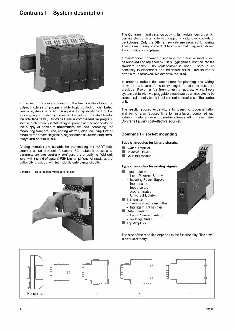
In the field of process automation, the functionality of input oroutput modules of programmable logic control or distributedcontrol systems is often inadequate for applications. For theensuing signal matching between the field and control levels,the interface family Contrans I has a comprehensive programinvolving electrically isolated signal processing components forthe supply of power to transmitters, for load increasing, formeasuring temperatures, setting alarms, also including furthermodules for processing binary signals such as switch amplifiers,relays and optocouplers.
Analog modules are suitable for transmitting the HART fieldcommunication protocol. A central PC makes it possible toparameterize and centrally configure the underlying field unitlevel with the aid of special FSK bus amplifiers. All modules areoptionally provided with intrinsically safe signal circuits.
The Contrans I family stands out with its modular design, whichpermits electronic units to be plugged in a standard sockets orbackplanes. Only the DIN rail sockets are required for wiring.This makes it easy to conduct functional matching even duringthe commissioning phase.
If maintenance becomes necessary, the defective module canbe removed and replaced by just plugging the substitute into thestandard socket. The replacement is done. There is nonecessity to disconnect and reconnect wires. One source oferror is thus removed. No expert is required.
In order to reduce the expenditure for planning and wiring,prewired backplanes for 8 or 16 plug-in function modules areprovided. Power is fed from a central source. A multi-coresystem cable with two pluggable ends enables all modules to beconnected directly to the input and output modules of the controlunit.
The result: reduced expenditure for planning, documentationand wiring; also reduced time for installation, combined withextrem maintenance- and user-friendliness. All of these makesContrans I a very cost-effective solution.
Contrans I – socket mounting
Type of modules for binary signals:
Switch Amplifier Solenoid Driver Coupling Module
Type of modules for analog signals:
Input Isolator– Loop Powered Supply– Isolating Power Supply– Input Isolator– Input Isolator,
programmable– Universal Isolator
Transmitter– Temperature Transmitter– Intelligent Transmitter
Output Isolator– Loop Powered Isolator– Isolating Driver
Trip Amplifier
The size of the modules depends to the functionality. The size 3is not used today.
Contrans I – Separation of wiring and function
Module size 1 2 3 4

Contrans I – System description
12.00 5
11 12 13
14 15 16
11 12 13
14 15 16
11 12 13
14 15 16
11 12 13
14 15 16
11 12 13
14 15 16
11 12 1313
14 15 16
11 12 13
14 15 16
11 12 13
14 15 16
11 12 13
14 15 16
11 12 13
14 15 16
11 12 13
14 15 16
11 12 13
14 15 16
11 12 13
14 15 16
11 12 1313
14 15 16
11 12 13
14 15 16
11 1212 13
14 15 16
11 12 13
14 15 16
11 12 13
14 15 16
11 12 13
14 15 16
11 12 13
14 15 16
11 12 13
14 15 16
1 2+ - + -
3 4
X103 X104
X105H101
X301X102
FSK 1...21 FSK 22...42
X302X106
FSK
X107
5 5 6 643 44
T3,15A
T2A
X101
1 2 1.3
1.6
2.3
2.6
3.3
3.6
4.3
4.6
5.3
5.6
6.3
6.6
7.3
7.6
8.3
8.6
9.3
9.6
10.3
10.6
11.3
11.6
12.3
12.6
13.3
13.6
14.3
14.6
15.3
15.6
16.3
16.6
17.3
17.6
18.3
18.6
19.3
19.6
20.3
20.6
21.3
21.6
1 2 1.4
1.5
2.4
2.5
3.4
3.5
4.4
4.5
5.4
5.5
6.4
6.5
7.4
7.5
8.4
8.5
9.4
9.5
10.4
10.5
11.4
11.5
12.4
12.5
13.4
13.5
14.4
14.5
15.4
15.5
16.4
16.5
17.4
17.5
18.4
18.5
19.4
19.5
20.4
20.5
21.4
21.5
24VDC
K101
1 2 3 4 5 6 7 8 9 10 11 12 13 14 15 16 17 18 19 20 21
3 54 6
16151412
1 1 432 2 44
+ - + -24 VDC K101X101 X102 X108
T2,5A T1,6A
13111097 864 5321
FSKFSK
11 12 13
14 15 16
11 12 13
14 15 16
11 12 13
14 15 16
11 12 13
14 15 16
11 12 13
14 15 16
11 12 13
14 15 16
11 12 13
14 15 16
11 12 13
14 15 16
11 12 13
14 15 16
11 12 13
14 15 16
11 12 13
14 15 16
11 12 13
14 15 16
11 12 13
14 15 16
11 12 13
14 15 16
11 12 13
14 15 16
11 12 13
14 15 16
11 12 13
14 15 16
11 12 13
14 15 16
11 12 13
14 15 16
11 12 13
14 15 16
11 12 13
14 15 16
11 12 13
14 15 16
11 12 13
14 15 16
11 12 13
14 15 16
T1,6A T2,5A
X103
X10
4
X10
2
24VDCX101
1 21.
31.
62.
32.
63.
33.
64.
34.
65.
35.
66.
36.
67.
37.
68.
38.
6
1 21.
41.
52.
42.
53.
43.
54.
44.
55.
45.
56.
46.
57.
47.
58.
48.
5
1
2
5656
+ -
1 2
1 2
+ -
7 864 5321
Customer-specified solutions
Backplanes can be fit according to customerrequirements.
21-way
21 slots for modules 2 slots for the FSK bus amplifier (HART) Redundant power supply and separate fusing for the power
distribution to the modules and for the signals.Dry contact for signalling of a fuse fault
Especially design for using with 19“ racks
8-way
8 slots for modules 1 slot for the FSK bus amplifier (HART) Power supply with separate fusing for the power distribution
to the modules and for the signals
16-way
16 slots for modules 1 slot for the FSK bus amplifier (HART) Redundant power supply and separate fusing for the
power distribution to the modules and for the signals.Dry contact for signalling of a fuse fault
Contrans I – Backplane mounting
Type of Backplanes:
Contrans I – System description
6 12.00
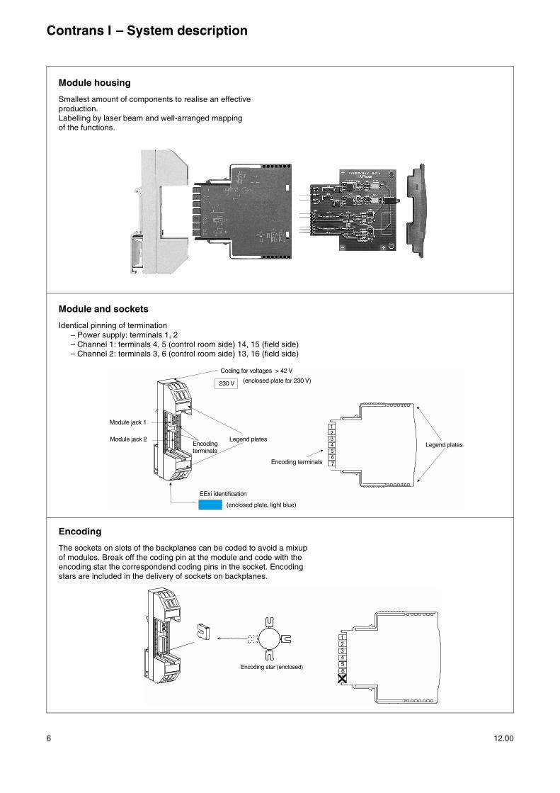
Module housing
Smallest amount of components to realise an effectiveproduction.Labelling by laser beam and well-arranged mapping of the functions.
Module and sockets
Identical pinning of termination– Power supply: terminals 1, 2– Channel 1: terminals 4, 5 (control room side) 14, 15 (field side)– Channel 2: terminals 3, 6 (control room side) 13, 16 (field side)
Encoding
The sockets on slots of the backplanes can be coded to avoid a mixupof modules. Break off the coding pin at the module and code with theencoding star the correspondend coding pins in the socket. Encodingstars are included in the delivery of sockets on backplanes.
1
34
2
67
5
230 V
EExi identification
Coding for voltages > 42 V
(enclosed plate, light blue)
(enclosed plate for 230 V)
Legend plates
Encoding terminals
Legend platesEncodingterminals
Module jack 1
Module jack 2
1
3
4
2
6
7
5Encoding star (enclosed)
Contrans I – System description
12.00 7
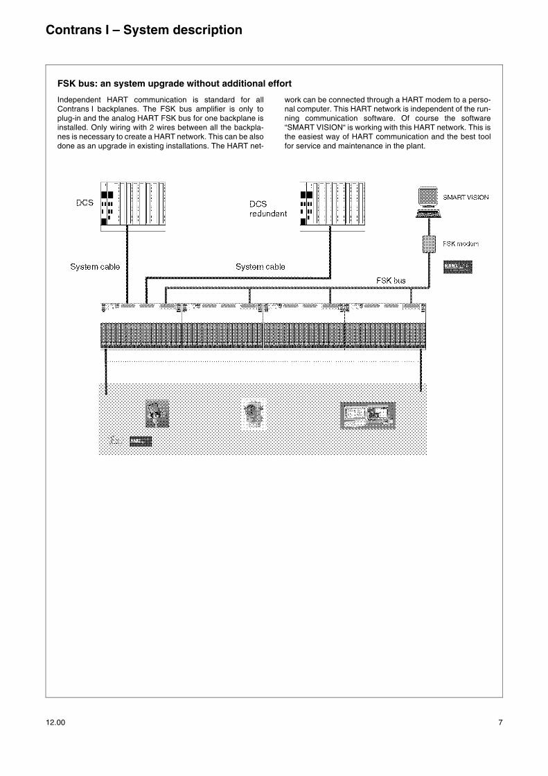
FSK bus: an system upgrade without additional effort
Independent HART communication is standard for allContrans I backplanes. The FSK bus amplifier is only toplug-in and the analog HART FSK bus for one backplane isinstalled. Only wiring with 2 wires between all the backpla-nes is necessary to create a HART network. This can be alsodone as an upgrade in existing installations. The HART net-
work can be connected through a HART modem to a perso-nal computer. This HART network is independent of the run-ning communication software. Of course the software“SMART VISION“ is working with this HART network. This isthe easiest way of HART communication and the best toolfor service and maintenance in the plant.

Contrans I – System description
8 12.00
General data
Mountingoutside hazardous areas
Mounting orientationvertical or horizontal
Storage temperature-25...85 °C
Operating temperature-20...60 °C; vertical mounting -20...55 °CFor the types V17151-74_, -75_, -34:at vertical mounting -20...40 °C(vertical mounting: top-hat rail vertical)
Relative humidity< 85 %, 3K3 to IEC 721, part 3-3, no condensation
Explosion protection
Prozess inputs or outputs[EEx ia] IIC or [EEx ia] IIB or [EEx ib] ...
Housing
MaterialPolycarbonate
Fire protection classV2 to UL 94 (DIN IEC 707)
ColourModule RAL 7043, dark greySocket, Backplane RAL 7035, light grey
Contact materialPhosphorous bronze, gold-plated 0.8 µm
Mechanical features
Transport/shoc30 g, 18 ms, 2M2 to DIN IEC 721, part 3-2
Function/Vibrations2 g/± 0.15 mm/5...150 Hz/3 x 5 cycles2 g/10 mm/1...35 Hz/3 x 1 cycle3M2 to DIN IEC 721, part 3-3
Functional data
All Contrans I Modules meet the requirements of the EMC gui-deline 89/336/EWG and the low voltage 73/23/EWG
Behaviour of analog modulesFeatures for reference condtions to DIN IEC 770
Electromagnetic compatibilityDIN EN 50081-2 (1992)DIN EN 50082-1 (1997)DIN EN 50082-2 (1995) are metNAMUR recommendation NE 21 is met
Functional modification through jumpersThe respective Data Sheets and block diagrams providesfunctional informations of the delivered device and matchingpossibilities of the modules.
The function can only be modified through jumpers off-line.To do this, remove the module from the socket or backplane.After removing the front panel with a screwdriver, the printedcircuit board can be pulled out from the housing.
Safety data
DIN EN 61010-1; DIN VDE 0411, part 1
Overvoltage categoryII
Degree of pollution2
Type of protection to EN 60259/DIN VDE 0470, part 1IP 20
Max. requirements on power supplies(for backplanes with 16 modules and approx. 3.1 W powerconsumption)
Power supply Max. inrushcurrent < 100 µs
Rated current
19.2 V24 V30 V
6.4 A8.0 A9.9 A
3.1 A2.5 A2.0 A
Binary Modules
12.00 9
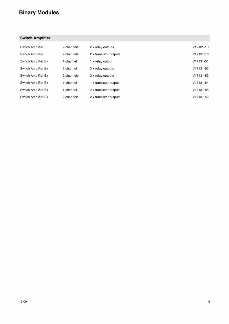
Switch Amplifier
Switch Amplifier 2 channels 2 x relay outputs V17131-13
Switch Amplifier 2 channels 2 x transistor outputs V17131-16
Switch Amplifier Ex 1 channel 1 x relay output V17131-51
Switch Amplifier Ex 1 channel 2 x relay outputs V17131-52
Switch Amplifier Ex 2 channels 2 x relay outputs V17131-53
Switch Amplifier Ex 1 channel 1 x transistor output V17131-54
Switch Amplifier Ex 1 channel 2 x transistor outputs V17131-55
Switch Amplifier Ex 2 channels 2 x transistor outputs V17131-56
Binary Modules
10 12.00
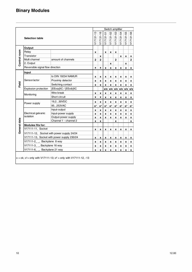
Selection table
V17
131-
13
V17
131-
16
V17
131-
51
V17
131-
52
V17
131-
53
V17
131-
54
V17
131-
55
V17
131-
56
Relay x x x xTransistor x x x xMulti channel amount of channels 2 2 2 22. Output x xReversible signal flow direction x x x x x x x x
to DIN 19234 NAMUR x x x x x x x xProximiy detector x x x x x x x xSwitching contact x x x x x x x x
Explosion protection [EExia]IIC / [EExib]IIC x/x x/x x/x x/x x/x x/xWire break x x x x x x x xShort circuit x x x x x x x x
19,2...30VDC x x x x x x x x95...253VAC o¹ o¹ o¹ o¹ o¹ o¹ o¹ o¹Input-output x x x x x x x xInput-power supply x x x x x x x xOutput-power supply x x x x x x x xChannel 1 - channel 2 x x x x
x x x x x x x x
V17111-13, Socket with power supply 230/24 x x x x x x x xV17111-2_ _, Backplane 8 way x x x x x x x xV17111-3_ _, Backplane 16 way x x x x x x x xV17111-6_ _, Backplane 21 way x x x x x x x x
x = ok; o¹= only with V17111-13; o² = only with V17111-12, -13
Switch amplifier
Gen
eral
dat
aC
on
tro
l ro
om
Electrical galvanic isolation
Fie
ld
Sensor/actor
Power supply
Monitoring
Output
Input
Modules fits for:V17111-11, Socket
V17111-12, Socket with power supply 24/24
11
ABB Automation Products GmbH · Borsigstr. 2 · D-63755 Alzenau · Phone +49(0)60 23 - 92 0 · Fax +49(0)60 23 - 92 33 00 · http://www.abb.com/automation
Subject to technical changes. Printed in the Fed. Rep. of Germany 12.00
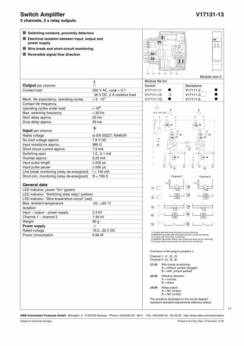
Switch Amplifier V17131-132 channels, 2 x relay outputs
Switching contacts, proximity detectors
Electrical isolation between input, output and power supply
Wire break and short-circuit monitoring
Reversible signal flow direction
Module size 2Module fits for:
Output per channel Socket BackplaneContact load 250 V AC, cosϕ > 0.7 V17111-11 V17111-2 _ _
30 V DC, 2 A resistive load V17111-12 V17111-3 _ _
Mech. life expectancy, operating cycles > 3 · 107 V17111-13 V17111-6 _ _
Contact life frequency,operating cycles under load > 106
Max. switching frequency < 20 HzStart delay approx. 20 msDrop delay approx. 20 ms
Input per channelRated voltage to EN 50227, NAMURNo load voltage approx. 7.8 V DCInput resistance approx. 980 ΩShort-circuit current approx. 7.9 mASwitching span 1.2...2.1 mAOverlap approx. 0.23 mAInput pulse length ≥ 500 µsInput pulse pause ≥ 500 µsLine break monitoring (relay de-energized) I < 150 mAShort-circ. monitoring (relay de-energized) R < 100 Ω
General dataLED indicator, power “On“ (green)LED indicator, “Switching state relay“ (yellow)LED indicator, “Wire break/short-circuit“ (red)Max. ambient temperature -20...+60 °CIsolationInput – output – power supply 2.3 kVChannel 1 – channel 2 1.35 kVWeight 90 gPower supplyRated voltage 19.2...30 V DCPower consumption 0.94 W
41 2 365
11
+ + + +– –
14 15
A B
J3
J2A B
A B
J1
12 13 16
A B
J6
J5
>1-
A B
A B
J4
A
J1 / 4
B
.
.
.
.
10 k
1 k 1 k
10 k 10 k
10 k
1)
2)
3)
4)
5)
+ -
A
J1 / 4
B
A
J1 / 4
B
A
J1 / 4
B
A
J1 / 4
B
19.2...30 V DC
Channel 1 Channel 2
1) Contact with wire break and short-circuit monitoring
3) Contact with wire break monitoring4) NAMUR transmitter without wire break and short-circuit monitoring5) Contact without wire break and short-circuit monitoring
2) NAMUR transmitter with wire break and short-circuit monitoring
gn
ye ye
rd
Functions of the plug-in jumpers J.:
Channel 1: J1, J2, J3Channel 2: J4, J5, J6
J1/J4 Wire break monitoringA = without, jumper pluggedB = with, jumper parked
J2/J5 Effective directionA = inverseB = direct
J3/J6 Relay outputA = NC contactB = NO contact
The positions illustrated on the circuit diagramrepresent standard adjustments (delivery status)
V17131-13
Contrans I
A
A
A
A
A
B
B
B
B
B
J6 J5J4 J1 J2J3
1 2
12
ABB Automation Products GmbH · Borsigstr. 2 · D-63755 Alzenau · Phone +49(0)60 23 - 92 0 · Fax +49(0)60 23 - 92 33 00 · http://www.abb.com/automation
Subject to technical changes. Printed in the Fed. Rep. of Germany 12.00
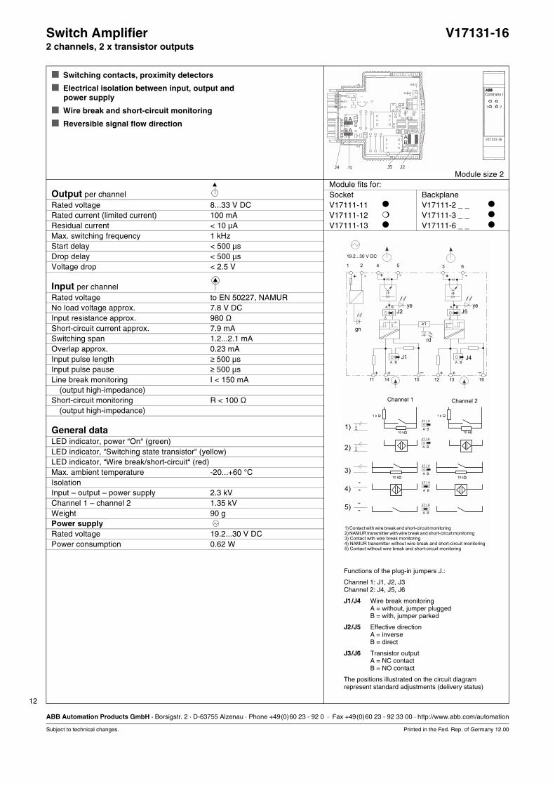
Switch Amplifier V17131-162 channels, 2 x transistor outputs
Switching contacts, proximity detectors
Electrical isolation between input, output and power supply
Wire break and short-circuit monitoring
Reversible signal flow direction
Module size 2Module fits for:
Output per channel Socket BackplaneRated voltage 8...33 V DC V17111-11 V17111-2 _ _
Rated current (limited current) 100 mA V17111-12 V17111-3 _ _
Residual current < 10 µA V17111-13 V17111-6 _ _
Max. switching frequency 1 kHzStart delay < 500 µsDrop delay < 500 µsVoltage drop < 2.5 V
Input per channelRated voltage to EN 50227, NAMURNo load voltage approx. 7.8 V DCInput resistance approx. 980 ΩShort-circuit current approx. 7.9 mASwitching span 1.2...2.1 mAOverlap approx. 0.23 mAInput pulse length ≥ 500 µsInput pulse pause ≥ 500 µsLine break monitoring I < 150 mA
(output high-impedance)Short-circuit monitoring R < 100 Ω
(output high-impedance)
General dataLED indicator, power “On“ (green)LED indicator, “Switching state transistor“ (yellow)LED indicator, “Wire break/short-circuit“ (red)Max. ambient temperature -20...+60 °CIsolationInput – output – power supply 2.3 kVChannel 1 – channel 2 1.35 kVWeight 90 gPower supplyRated voltage 19.2...30 V DCPower consumption 0.62 W
Functions of the plug-in jumpers J.:
Channel 1: J1, J2, J3Channel 2: J4, J5, J6
J1/J4 Wire break monitoringA = without, jumper pluggedB = with, jumper parked
J2/J5 Effective directionA = inverseB = direct
J3/J6 Transistor outputA = NC contactB = NO contact
The positions illustrated on the circuit diagramrepresent standard adjustments (delivery status)
41 2 3 65
11 14 15
J2A B
A B
J1
12 13 16
J5
>1-
A B
A BJ4
.
.
.
.
10 k
1 k 1 k
10 k 10 k
10 k
1)
2)
3)
4)
5)
+ - -- + +
+ + – –+ +
A
J1 / 4
B
A
J1 / 4
B
A
J1 / 4
B
A
J1 / 4
B
A
J1 / 4
B
Channel 1 Channel 2
1) Contact with wire break and short-circuit monitoring
3) Contact with wire break monitoring4) NAMUR transmitter without wire break and short-circuit monitoring5) Contact without wire break and short-circuit monitoring
2) NAMUR transmitter with wire break and short-circuit monitoring
19.2...30 V DC
gn
ye ye
rd
V17131-16
Contrans I
A
A
AB
B
B
J5J4 J1 J2
1 2
13
ABB Automation Products GmbH · Borsigstr. 2 · D-63755 Alzenau · Phone +49(0)60 23 - 92 0 · Fax +49(0)60 23 - 92 33 00 · http://www.abb.com/automation
Subject to technical changes. Printed in the Fed. Rep. of Germany 12.00
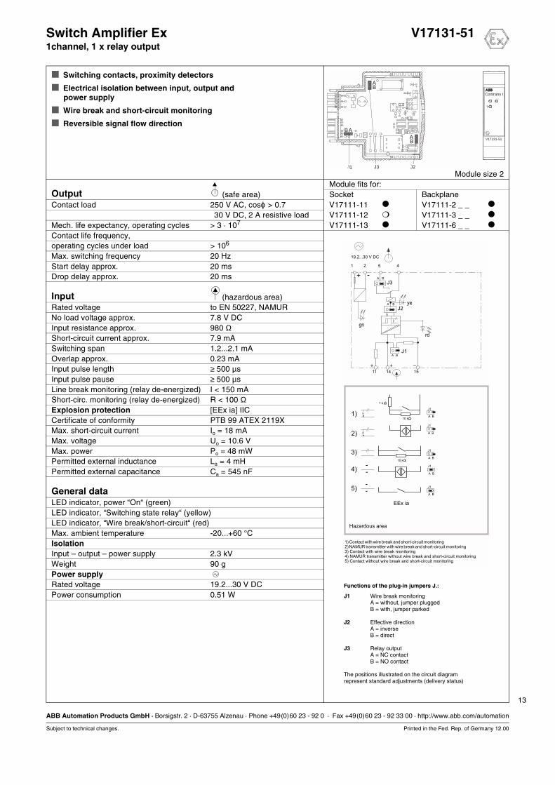
Switch Amplifier Ex V17131-511channel, 1 x relay output
Switching contacts, proximity detectors
Electrical isolation between input, output and power supply
Wire break and short-circuit monitoring
Reversible signal flow direction
Module size 2Module fits for:
Output (safe area) Socket BackplaneContact load 250 V AC, cosϕ > 0.7 V17111-11 V17111-2 _ _
30 V DC, 2 A resistive load V17111-12 V17111-3 _ _
Mech. life expectancy, operating cycles > 3 · 107 V17111-13 V17111-6 _ _
Contact life frequency,operating cycles under load > 106
Max. switching frequency 20 HzStart delay approx. 20 msDrop delay approx. 20 ms
Input (hazardous area)Rated voltage to EN 50227, NAMURNo load voltage approx. 7.8 V DCInput resistance approx. 980 ΩShort-circuit current approx. 7.9 mASwitching span 1.2...2.1 mAOverlap approx. 0.23 mAInput pulse length ≥ 500 µsInput pulse pause ≥ 500 µsLine break monitoring (relay de-energized) I < 150 mAShort-circ. monitoring (relay de-energized) R < 100 ΩExplosion protection [EEx ia] IICCertificate of conformity PTB 99 ATEX 2119XMax. short-circuit current Io = 18 mAMax. voltage Uo = 10.6 VMax. power Po = 48 mWPermitted external inductance La = 4 mHPermitted external capacitance Ca = 545 nF
General dataLED indicator, power “On“ (green)LED indicator, “Switching state relay“ (yellow)LED indicator, “Wire break/short-circuit“ (red)Max. ambient temperature -20...+60 °CIsolationInput – output – power supply 2.3 kVWeight 90 gPower supplyRated voltage 19.2...30 V DCPower consumption 0.51 W
Functions of the plug-in jumpers J.:
J1 Wire break monitoringA = without, jumper pluggedB = with, jumper parked
J2 Effective directionA = inverseB = direct
J3 Relay outputA = NC contactB = NO contact
The positions illustrated on the circuit diagramrepresent standard adjustments (delivery status)
41 2 5
11 14 15
A B
J3
J2A B
A BJ1
.
.
.
.
10 k
1 k
10 k
1)
2)
3)
4)
5)
+ -
+ + –
EEx ia
A
J1
B
A
J1
B
A
J1
B
A
J1
B
A
J1
B
Hazardous area
1) Contact with wire break and short-circuit monitoring
3) Contact with wire break monitoring4) NAMUR transmitter without wire break and short-circuit monitoring5) Contact without wire break and short-circuit monitoring
2) NAMUR transmitter with wire break and short-circuit monitoring
19.2...30 V DC
gn
ye
rd
V17131-51
Contrans I
A
AA
B
B
B
J1 J2J3
1
14
ABB Automation Products GmbH · Borsigstr. 2 · D-63755 Alzenau · Phone +49(0)60 23 - 92 0 · Fax +49(0)60 23 - 92 33 00 · http://www.abb.com/automation
Subject to technical changes. Printed in the Fed. Rep. of Germany 12.00
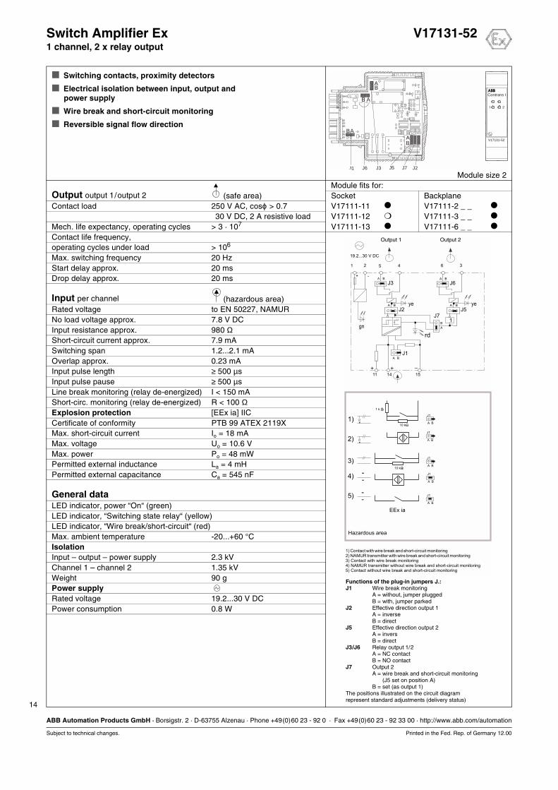
Switch Amplifier Ex V17131-521 channel, 2 x relay output
Switching contacts, proximity detectors
Electrical isolation between input, output and power supply
Wire break and short-circuit monitoring
Reversible signal flow direction
Module size 2Module fits for:
Output output 1/output 2 (safe area) Socket BackplaneContact load 250 V AC, cosϕ > 0.7 V17111-11 V17111-2 _ _
30 V DC, 2 A resistive load V17111-12 V17111-3 _ _
Mech. life expectancy, operating cycles > 3 · 107 V17111-13 V17111-6 _ _
Contact life frequency,operating cycles under load > 106
Max. switching frequency 20 HzStart delay approx. 20 msDrop delay approx. 20 ms
Input per channel (hazardous area)Rated voltage to EN 50227, NAMURNo load voltage approx. 7.8 V DCInput resistance approx. 980 ΩShort-circuit current approx. 7.9 mASwitching span 1.2...2.1 mAOverlap approx. 0.23 mAInput pulse length ≥ 500 µsInput pulse pause ≥ 500 µsLine break monitoring (relay de-energized) I < 150 mAShort-circ. monitoring (relay de-energized) R < 100 ΩExplosion protection [EEx ia] IICCertificate of conformity PTB 99 ATEX 2119XMax. short-circuit current Io = 18 mAMax. voltage Uo = 10.6 VMax. power Po = 48 mWPermitted external inductance La = 4 mHPermitted external capacitance Ca = 545 nF
General dataLED indicator, power “On“ (green)LED indicator, “Switching state relay“ (yellow)LED indicator, “Wire break/short-circuit“ (red)Max. ambient temperature -20...+60 °CIsolationInput – output – power supply 2.3 kVChannel 1 – channel 2 1.35 kVWeight 90 gPower supplyRated voltage 19.2...30 V DCPower consumption 0.8 W
Functions of the plug-in jumpers J.:J1 Wire break monitoring
A = without, jumper pluggedB = with, jumper parked
J2 Effective direction output 1A = inverseB = direct
J5 Effective direction output 2A = inversB = direct
J3/J6 Relay output 1/2A = NC contactB = NO contact
J7 Output 2A = wire break and short-circuit monitoringA = (J5 set on position A)B = set (as output 1)
The positions illustrated on the circuit diagramrepresent standard adjustments (delivery status)
41 2 365
11 14 15
A B
J3
J2A B
A B
J1
A B
J6
J5J7
A B
A
B
.
.
.
.
10 k
1 k
10 k
1)
2)
3)
4)
5)
1
+ -
+ + –
EEx ia
A
J1
B
A
J1
B
A
J1
B
A
J1
B
A
J1
B
Hazardous area
1) Contact with wire break and short-circuit monitoring
3) Contact with wire break monitoring4) NAMUR transmitter without wire break and short-circuit monitoring5) Contact without wire break and short-circuit monitoring
2) NAMUR transmitter with wire break and short-circuit monitoring
19.2...30 V DC
Output 1 Output 2
gn
ye ye
rd
V17131-52
Contrans I
A
A
AA
B
B
B
B
J6 J5J1 J7 J2J3
1 2
15
ABB Automation Products GmbH · Borsigstr. 2 · D-63755 Alzenau · Phone +49(0)60 23 - 92 0 · Fax +49(0)60 23 - 92 33 00 · http://www.abb.com/automation
Subject to technical changes. Printed in the Fed. Rep. of Germany 12.00
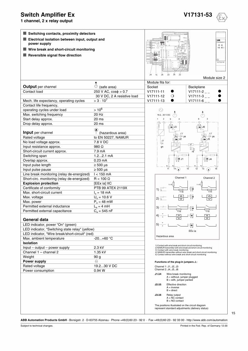
Switch Amplifier Ex V17131-531 channel, 2 x relay output
Switching contacts, proximity detectors
Electrical isolation between input, output and power supply
Wire break and short-circuit monitoring
Reversible signal flow direction
Module size 2Module fits for:
Output per channel (safe area) Socket BackplaneContact load 250 V AC, cosϕ > 0.7 V17111-11 V17111-2 _ _
30 V DC, 2 A resistive load V17111-12 V17111-3 _ _
Mech. life expectancy, operating cycles > 3 · 107 V17111-13 V17111-6 _ _
Contact life frequency,operating cycles under load > 106
Max. switching frequency 20 HzStart delay approx. 20 msDrop delay approx. 20 ms
Input per channel (hazardous area)Rated voltage to EN 50227, NAMURNo load voltage approx. 7.8 V DCInput resistance approx. 980 ΩShort-circuit current approx. 7.9 mASwitching span 1.2...2.1 mAOverlap approx. 0.23 mAInput pulse length ≥ 500 µsInput pulse pause ≥ 500 µsLine break monitoring (relay de-energized) I < 150 mAShort-circ. monitoring (relay de-energized) R < 100 ΩExplosion protection [EEx ia] IICCertificate of conformity PTB 99 ATEX 2119XMax. short-circuit current Io = 18 mAMax. voltage Uo = 10.6 VMax. power Po = 48 mWPermitted external inductance La = 4 mHPermitted external capacitance Ca = 545 nF
General dataLED indicator, power “On“ (green)LED indicator, “Switching state relay“ (yellow)LED indicator, “Wire break/short-circuit“ (red)Max. ambient temperature -20...+60 °CIsolationInput – output – power supply 2.3 kVChannel 1 – channel 2 1.35 kVWeight 90 gPower supplyRated voltage 19.2...30 V DCPower consumption 0.94 W
41 2 365
11 14 15
A B
J3
J2A B
A B
J1
12 13 16
A B
J6
J5
>1-
A B
A BJ4
.
.
.
.
10 k
1 k 1 k
10 k 10 k
10 k
1)
2)
3)
4)
5)
+ -
+ + + + ––
EEx ia
A
J1 / 4
B
A
J1 / 4
B
A
J1 / 4
B
A
J1 / 4
B
A
J1 / 4
B
Hazardous area
Channel 1 Channel 2
1) Contact with wire break and short-circuit monitoring
3) Contact with wire break monitoring4) NAMUR transmitter without wire break and short-circuit monitoring5) Contact without wire break and short-circuit monitoring
2) NAMUR transmitter with wire break and short-circuit monitoring
19.2...30 V DC
gn
ye ye
rd
Functions of the plug-in jumpers J.:
Channel 1: J1, J2, J3Channel 2: J4, J5, J6
J1/J4 Wire break monitoringA = without, jumper pluggedB = with, jumper parked
J2/J5 Effective directionA = inverseB = direct
J3/J6 Relay outputA = NC contactB = NO contact
The positions illustrated on the circuit diagramrepresent standard adjustments (delivery status)
V17131-53
Contrans I
A
A
A
A
A
B
B
B
B
B
J6 J5J4 J1 J2J3
1 2
16
ABB Automation Products GmbH · Borsigstr. 2 · D-63755 Alzenau · Phone +49(0)60 23 - 92 0 · Fax +49(0)60 23 - 92 33 00 · http://www.abb.com/automation
Subject to technical changes. Printed in the Fed. Rep. of Germany 12.00
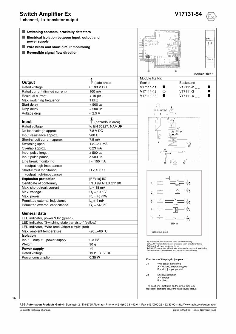
Switch Amplifier Ex V17131-541 channel, 1 x transistor output
Switching contacts, proximity detectors
Electrical isolation between input, output and power supply
Wire break and short-circuit monitoring
Reversible signal flow direction
Module size 2Module fits for:
Output (safe area) Socket BackplaneRated voltage 8...33 V DC V17111-11 V17111-2 _ _
Rated current (limited current) 100 mA V17111-12 V17111-3 _ _
Residual current < 10 µA V17111-13 V17111-6 _ _
Max. switching frequency 1 kHzStart delay < 500 µsDrop delay < 500 µsVoltage drop < 2.5 V
Input (hazardous area)Rated voltage to EN 50227, NAMURNo load voltage approx. 7.8 V DCInput resistance approx. 980 ΩShort-circuit current approx. 7.9 mASwitching span 1.2...2.1 mAOverlap approx. 0.23 mAInput pulse length ≥ 500 µsInput pulse pause ≥ 500 µsLine break monitoring I < 150 mA
(output high-impedance)Short-circuit monitoring R < 100 Ω
(output high-impedance)Explosion protection [EEx ia] IICCertificate of conformity PTB 99 ATEX 2119XMax. short-circuit current Io = 18 mAMax. voltage Uo = 10.6 VMax. power Po = 48 mWPermitted external inductance La = 4 mHPermitted external capacitance Ca = 545 nF
General dataLED indicator, power “On“ (green)LED indicator, “Switching state transistor“ (yellow)LED indicator, “Wire break/short-circuit“ (red)Max. ambient temperature -20...+60 °CIsolationInput – output – power supply 2.3 kVWeight 90 gPower supplyRated voltage 19.2...30 V DCPower consumption 0.35 W
Functions of the plug-in jumpers J.:
J1 Wire break monitoringA = without, jumper pluggedB = with, jumper parked
J2 Effective directionA = inverseB = direct
The positions illustrated on the circuit diagramrepresent standard adjustments (delivery status)
51 2 4
11 14 15
J2A B
A B
J1
.
.
.
.
10 k
1 k
10 k
1)
2)
3)
4)
5)
+ +
+ +
-
-
-
EEx ia
A
J1
B
A
J1
B
A
J1
B
A
J1
B
A
J1
B
Hazardous area
1) Contact with wire break and short-circuit monitoring
3) Contact with wire break monitoring4) NAMUR transmitter without wire break and short-circuit monitoring5) Contact without wire break and short-circuit monitoring
2) NAMUR transmitter with wire break and short-circuit monitoring
19.2...30 V DC
gn
ye
rd
V17131-54
Contrans I
AA
B
B
J1
1
J2
17
ABB Automation Products GmbH · Borsigstr. 2 · D-63755 Alzenau · Phone +49(0)60 23 - 92 0 · Fax +49(0)60 23 - 92 33 00 · http://www.abb.com/automation
Subject to technical changes. Printed in the Fed. Rep. of Germany 12.00
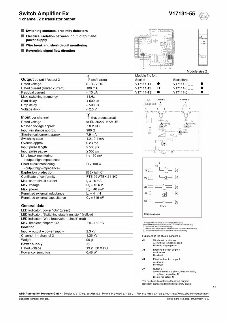
Switch Amplifier Ex V17131-551 channel, 2 x transistor output
Switching contacts, proximity detectors
Electrical isolation between input, output and power supply
Wire break and short-circuit monitoring
Reversible signal flow direction
Module size 2Module fits for:
Output output 1/output 2 (safe area) Socket BackplaneRated voltage 8...33 V DC V17111-11 V17111-2 _ _
Rated current (limited current) 100 mA V17111-12 V17111-3 _ _
Residual current < 10 µA V17111-13 V17111-6 _ _
Max. switching frequency 1 kHzStart delay < 500 µsDrop delay < 500 µsVoltage drop < 2.5 V
Input per channel (hazardous area)Rated voltage to EN 50227, NAMURNo load voltage approx. 7.8 V DCInput resistance approx. 980 ΩShort-circuit current approx. 7.9 mASwitching span 1.2...2.1 mAOverlap approx. 0.23 mAInput pulse length ≥ 500 µsInput pulse pause ≥ 500 µsLine break monitoring I < 150 mA
(output high-impedance)Short-circuit monitoring R < 100 Ω
(output high-impedance)Explosion protection [EEx ia] IICCertificate of conformity PTB 99 ATEX 2119XMax. short-circuit current Io = 18 mAMax. voltage Uo = 10.6 VMax. power Po = 48 mWPermitted external inductance La = 4 mHPermitted external capacitance Ca = 545 nF
General dataLED indicator, power “On“ (green)LED indicator, “Switching state transistor“ (yellow)LED indicator, “Wire break/short-circuit“ (red)Max. ambient temperature -20...+60 °CIsolationInput – output – power supply 2.3 kVChannel 1 – channel 2 1.35 kVWeight 90 gPower supplyRated voltage 19.2...30 V DCPower consumption 0.48 W
Functions of the plug-in jumpers J.:
J1 Wire break monitoringA = without, jumper pluggedB = with, jumper parked
J2 Effective direction output 1A = inverseB = direct
J5 Effective direction output 2A = inversB = direct
J7 Output 2A = wire break and short-circuit monitoringA = (J5 set on position A)B = set (as output 1)
The positions illustrated on the circuit diagramrepresent standard adjustments (delivery status)
41 2 3 65
11 14 15
J2A B
A B
J1
J5J7
AB
A
B
.
.
.
.
10 k
1 k
10 k
1)
2)
3)
4)
5)
1
+ + + ---
+ + –
EEx ia
A
J1
B
A
J1
B
A
J1
B
A
J1
B
A
J1
B
Hazardous area
19.2...30 V DC
1) Contact with wire break and short-circuit monitoring
3) Contact with wire break monitoring4) NAMUR transmitter without wire break and short-circuit monitoring5) Contact without wire break and short-circuit monitoring
2) NAMUR transmitter with wire break and short-circuit monitoring
Channel 1 Channel 2
gn
ye ye
rd
V17131-55
Contrans I
AA
B
B
J5J1
1 2
J7 J2
18
ABB Automation Products GmbH · Borsigstr. 2 · D-63755 Alzenau · Phone +49(0)60 23 - 92 0 · Fax +49(0)60 23 - 92 33 00 · http://www.abb.com/automation
Subject to technical changes. Printed in the Fed. Rep. of Germany 12.00
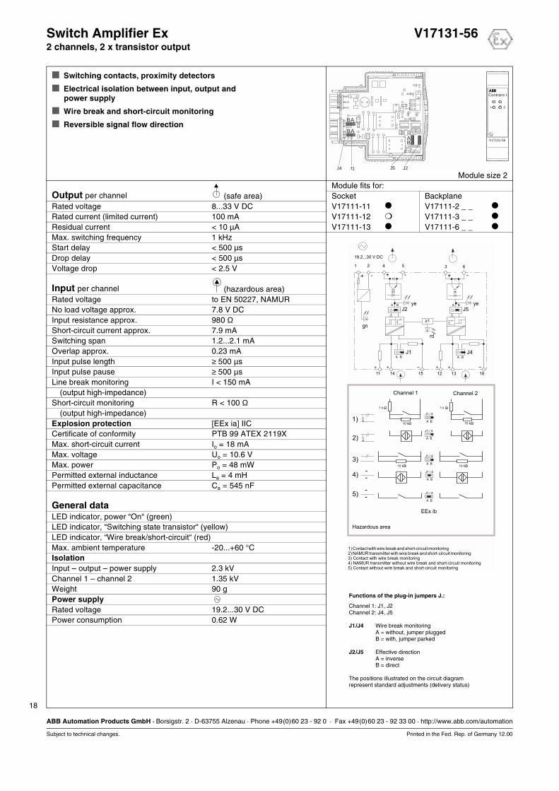
Switch Amplifier Ex V17131-562 channels, 2 x transistor output
Switching contacts, proximity detectors
Electrical isolation between input, output and power supply
Wire break and short-circuit monitoring
Reversible signal flow direction
Module size 2Module fits for:
Output per channel (safe area) Socket BackplaneRated voltage 8...33 V DC V17111-11 V17111-2 _ _
Rated current (limited current) 100 mA V17111-12 V17111-3 _ _
Residual current < 10 µA V17111-13 V17111-6 _ _
Max. switching frequency 1 kHzStart delay < 500 µsDrop delay < 500 µsVoltage drop < 2.5 V
Input per channel (hazardous area)Rated voltage to EN 50227, NAMURNo load voltage approx. 7.8 V DCInput resistance approx. 980 ΩShort-circuit current approx. 7.9 mASwitching span 1.2...2.1 mAOverlap approx. 0.23 mAInput pulse length ≥ 500 µsInput pulse pause ≥ 500 µsLine break monitoring I < 150 mA
(output high-impedance)Short-circuit monitoring R < 100 Ω
(output high-impedance)Explosion protection [EEx ia] IICCertificate of conformity PTB 99 ATEX 2119XMax. short-circuit current Io = 18 mAMax. voltage Uo = 10.6 VMax. power Po = 48 mWPermitted external inductance La = 4 mHPermitted external capacitance Ca = 545 nF
General dataLED indicator, power “On“ (green)LED indicator, “Switching state transistor“ (yellow)LED indicator, “Wire break/short-circuit“ (red)Max. ambient temperature -20...+60 °CIsolationInput – output – power supply 2.3 kVChannel 1 – channel 2 1.35 kVWeight 90 gPower supplyRated voltage 19.2...30 V DCPower consumption 0.62 W
Functions of the plug-in jumpers J.:
Channel 1: J1, J2Channel 2: J4, J5
J1/J4 Wire break monitoringA = without, jumper pluggedB = with, jumper parked
J2/J5 Effective directionA = inverseB = direct
The positions illustrated on the circuit diagramrepresent standard adjustments (delivery status)
41 2 3 65
11 14 15
J2A B
A B
J1
12 13 16
J5
>1-
A B
A B
J4
.
.
.
.
10 k
1 k 1 k
10 k 10 k
10 k
1)
2)
3)
4)
5)
+ - -- + +
+ + + +– –
EEx ib
A
J1 / 4
B
A
J1 / 4
B
A
J1 / 4
B
A
J1 / 4
B
A
J1 / 4
B
Hazardous area
Channel 1 Channel 2
19.2...30 V DC
1) Contact with wire break and short-circuit monitoring
3) Contact with wire break monitoring4) NAMUR transmitter without wire break and short-circuit monitoring5) Contact without wire break and short-circuit monitoring
2) NAMUR transmitter with wire break and short-circuit monitoring
gn
ye ye
rd
V17131-56
Contrans I
A
A
AB
B
B
J5J4 J1 J2
1 2

Binary Modules
12.00 19
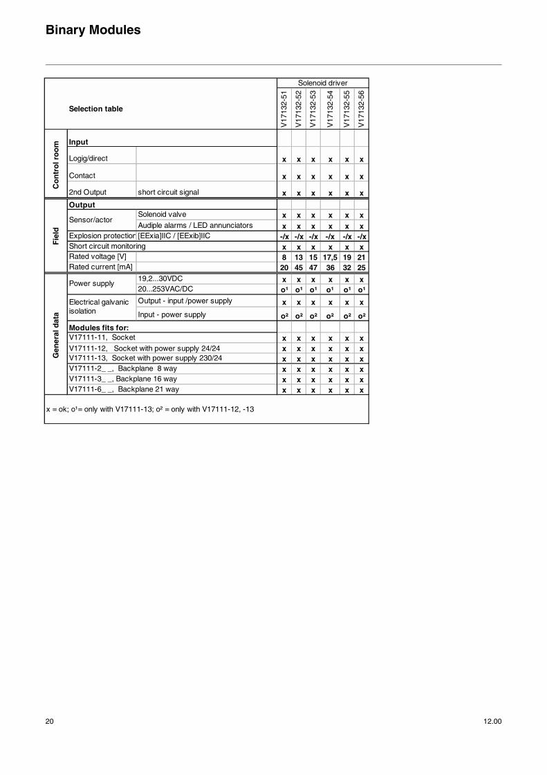
Solenoid Drivers
Solenoid Drivers Ex 8/20 V17132-51
Solenoid Drivers Ex 13/45 V17132-52
Solenoid Drivers Ex 15/47 V17132-53
Solenoid Drivers Ex 17.5/36 V17132-54
Solenoid Drivers Ex 19/32 V17132-55
Solenoid Drivers Ex 21/25 V17132-56
Binary Modules
20 12.00
Selection table
V17
132-
51
V17
132-
52
V17
132-
53
V17
132-
54
V17
132-
55
V17
132-
56
Logig/direct x x x x x x
Contact x x x x x x
2nd Output short circuit signal x x x x x x
Solenoid valve x x x x x xAudiple alarms / LED annunciators x x x x x x
Explosion protection [EExia]IIC / [EExib]IIC -/x -/x -/x -/x -/x -/xShort circuit monitoring x x x x x xRated voltage [V] 8 13 15 17,5 19 21Rated current [mA] 20 45 47 36 32 25
19,2...30VDC x x x x x x20...253VAC/DC o¹ o¹ o¹ o¹ o¹ o¹Output - input /power supply x x x x x x
Input - power supply o² o² o² o² o² o²
x x x x x xx x x x x x
V17111-13, Socket with power supply 230/24 x x x x x xV17111-2_ _, Backplane 8 way x x x x x xV17111-3_ _, Backplane 16 way x x x x x xV17111-6_ _, Backplane 21 way x x x x x x
x = ok; o¹= only with V17111-13; o² = only with V17111-12, -13
Gen
eral
dat
a
Power supply
Electrical galvanic isolation
V17111-11, Socket
V17111-12, Socket with power supply 24/24
Modules fits for:
Solenoid driver
Fie
ld
Sensor/actor
Input
Output
Co
ntr
ol r
oo
m
21
ABB Automation Products GmbH · Borsigstr. 2 · D-63755 Alzenau · Phone +49(0)60 23 - 92 0 · Fax +49(0)60 23 - 92 33 00 · http://www.abb.com/automation
Subject to technical changes. Printed in the Fed. Rep. of Germany 12.00
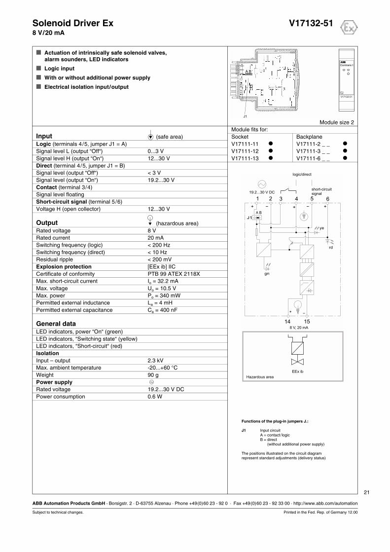
Solenoid Driver Ex V17132-518 V/20 mA
Actuation of intrinsically safe solenoid valves,alarm sounders, LED indicators
Logic input
With or without additional power supply
Electrical isolation input/output
Module size 2Module fits for:
Input (safe area) Socket BackplaneLogic (terminals 4/5, jumper J1 = A) V17111-11 V17111-2 _ _
Signal level L (output “Off“) 0...3 V V17111-12 V17111-3 _ _
Signal level H (output “On“) 12...30 V V17111-13 V17111-6 _ _
Direct (terminal 4/5, jumper J1 = B)Signal level (output “Off“) < 3 VSignal level (output “On“) 19.2...30 VContact (terminal 3/4)Signal level floatingShort-circuit signal (terminal 5/6)Voltage H (open collector) 12...30 V
Output (hazardous area)Rated voltage 8 VRated current 20 mASwitching frequency (logic) < 200 HzSwitching frequency (direct) < 10 HzResidual ripple < 200 mVExplosion protection [EEx ib] IICCertificate of conformity PTB 99 ATEX 2118XMax. short-circuit current Io = 32.2 mAMax. voltage Uo = 10.5 VMax. power Po = 340 mWPermitted external inductance La = 4 mHPermitted external capacitance Ca = 400 nF
General dataLED indicators, power “On“ (green)LED indicators, “Switching state“ (yellow)LED indicators, “Short-circuit“ (red)IsolationInput – output 2.3 kVMax. ambient temperature -20...+60 °CWeight 90 gPower supplyRated voltage 19.2...30 V DCPower consumption 0.6 W
41 2 3 5 6
14 15
A
J1
+ - +
+ -
8 V, 20 mA
- +
B
EEx ib
Hazardous area
logic/direct
short-circuitsignal19.2...30 V DC
gn
rd
ye
Functions of the plug-in jumpers J.:
J1 Input circuitA = contact /logicB = directB = (without additional power supply)
The positions illustrated on the circuit diagramrepresent standard adjustments (delivery status)

22
ABB Automation Products GmbH · Borsigstr. 2 · D-63755 Alzenau · Phone +49(0)60 23 - 92 0 · Fax +49(0)60 23 - 92 33 00 · http://www.abb.com/automation
Subject to technical changes. Printed in the Fed. Rep. of Germany 12.00
Solenoid Driver Ex V17132-5213 V/45 mA
Actuation of intrinsically safe solenoid valves,alarm sounders, LED indicators
Logic input
With or without additional power supply
Electrical isolation input/output
Module size 2Module fits for:
Input (safe area) Socket BackplaneLogic (terminals 4/5, jumper J1 = A) V17111-11 V17111-2 _ _
Signal level L (output “Off“) 0...3 V V17111-12 V17111-3 _ _
Signal level H (output “On“) 12...30 V V17111-13 V17111-6 _ _
Direct (terminal 4/5, jumper J1 = B)Signal level (output “Off“) < 3 VSignal level (output “On“) 19.2...30 VContact (terminal 3/4)Signal level floatingShort-circuit signal (terminal 5/6)Voltage H (open collector) 12...30 V
Output (hazardous area)Rated voltage 13 VRated current 45 mASwitching frequency (logic) < 200 HzSwitching frequency (direct) < 10 HzResidual ripple < 200 mVExplosion protection [EEx ib] IICCertificate of conformity PTB 99 ATEX 2118XMax. short-circuit current Io = 52 mAMax. voltage Uo = 15.8 VMax. power Po = 820 mWPermitted external inductance La = 1.5 mHPermitted external capacitance Ca = 160 nF
General dataLED indicators, power “On“ (green)LED indicators, “Switching state“ (yellow)LED indicators, “Short-circuit“ (red)IsolationInput – output 2.3 kVMax. ambient temperature -20...+60 °CWeight 90 gPower supplyRated voltage 19.2...30 V DCPower consumption 1.5 W
Functions of the plug-in jumpers J.:
J1 Input circuitA = contact /logicB = directB = (without additional power supply)
The positions illustrated on the circuit diagramrepresent standard adjustments (delivery status)
41 2 3 5 6
14 15
A
J1
+ - +
+ -
13 V, 45 mA
- +
B
EEx ib
Hazardous area
logic/direct
short-circuitsignal19.2...30 V DC
gn
rd
ye
23
ABB Automation Products GmbH · Borsigstr. 2 · D-63755 Alzenau · Phone +49(0)60 23 - 92 0 · Fax +49(0)60 23 - 92 33 00 · http://www.abb.com/automation
Subject to technical changes. Printed in the Fed. Rep. of Germany 12.00
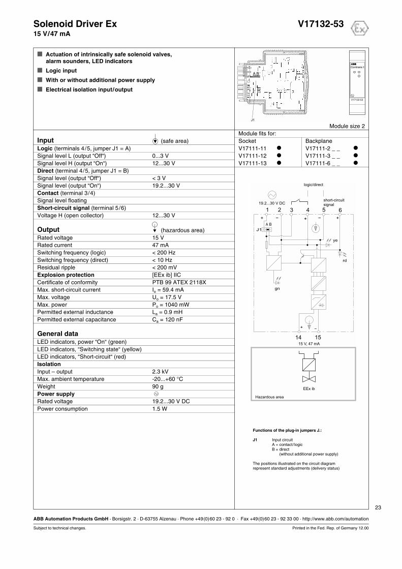
Solenoid Driver Ex V17132-5315 V/47 mA
Actuation of intrinsically safe solenoid valves,alarm sounders, LED indicators
Logic input
With or without additional power supply
Electrical isolation input/output
Module size 2Module fits for:
Input (safe area) Socket BackplaneLogic (terminals 4/5, jumper J1 = A) V17111-11 V17111-2 _ _
Signal level L (output “Off“) 0...3 V V17111-12 V17111-3 _ _
Signal level H (output “On“) 12...30 V V17111-13 V17111-6 _ _
Direct (terminal 4/5, jumper J1 = B)Signal level (output “Off“) < 3 VSignal level (output “On“) 19.2...30 VContact (terminal 3/4)Signal level floatingShort-circuit signal (terminal 5/6)Voltage H (open collector) 12...30 V
Output (hazardous area)Rated voltage 15 VRated current 47 mASwitching frequency (logic) < 200 HzSwitching frequency (direct) < 10 HzResidual ripple < 200 mVExplosion protection [EEx ib] IICCertificate of conformity PTB 99 ATEX 2118XMax. short-circuit current Io = 59.4 mAMax. voltage Uo = 17.5 VMax. power Po = 1040 mWPermitted external inductance La = 0.9 mHPermitted external capacitance Ca = 120 nF
General dataLED indicators, power “On“ (green)LED indicators, “Switching state“ (yellow)LED indicators, “Short-circuit“ (red)IsolationInput – output 2.3 kVMax. ambient temperature -20...+60 °CWeight 90 gPower supplyRated voltage 19.2...30 V DCPower consumption 1.5 W
Functions of the plug-in jumpers J.:
J1 Input circuitA = contact/logicB = directB = (without additional power supply)
The positions illustrated on the circuit diagramrepresent standard adjustments (delivery status)
41 2 3 5 6
14 15
A
J1
+ - +
+ -
15 V, 47 mA
- +
B
EEx ib
Hazardous area
logic/direct
short-circuitsignal19.2...30 V DC
rd
gn
ye

24
ABB Automation Products GmbH · Borsigstr. 2 · D-63755 Alzenau · Phone +49(0)60 23 - 92 0 · Fax +49(0)60 23 - 92 33 00 · http://www.abb.com/automation
Subject to technical changes. Printed in the Fed. Rep. of Germany 12.00
Solenoid Driver Ex V17132-5417.5 V/36 mA
Actuation of intrinsically safe solenoid valves,alarm sounders, LED indicators
Logic input
With or without additional power supply
Electrical isolation input/output
Module size 2Module fits for:
Input (safe area) Socket BackplaneLogic (terminals 4/5, jumper J1 = A) V17111-11 V17111-2 _ _
Signal level L (output “Off“) 0...3 V V17111-12 V17111-3 _ _
Signal level H (output “On“) 12...30 V V17111-13 V17111-6 _ _
Direct (terminal 4/5, jumper J1 = B)Signal level (output “Off“) < 3 VSignal level (output “On“) 19.2...30 VContact (terminal 3/4)Signal level floatingShort-circuit signal (terminal 5/6)Voltage H (open collector) 12...30 V
Output (hazardous area)Rated voltage 17.5 VRated current 36 mASwitching frequency (logic) < 200 HzSwitching frequency (direct) < 10 HzResidual ripple < 200 mVExplosion protection [EEx ib] IICCertificate of conformity PTB 99 ATEX 2118XMax. short-circuit current Io = 45 mAMax. voltage Uo = 21 VMax. power Po = 950 mWPermitted external inductance La = 0.6 mHPermitted external capacitance Ca = 79 nF
General dataLED indicators, power “On“ (green)LED indicators, “Switching state“ (yellow)LED indicators, “Short-circuit“ (red)IsolationInput – output 2.3 kVMax. ambient temperature -20...+60 °CWeight 90 gPower supplyRated voltage 19.2...30 V DCPower consumption 1.5 W
Functions of the plug-in jumpers J.:
J1 Input circuitA = contact /logicB = directB = (without additional power supply)
The positions illustrated on the circuit diagramrepresent standard adjustments (delivery status)
41 2 3 5 6
14 15
A
J1
+ - +
+ -
- +
B
EEx ib
Hazardous area
logic/direct
short-circuitsignal19.2...30 V DC
gn
rd
ye
17.5 V, 36 mA

25
ABB Automation Products GmbH · Borsigstr. 2 · D-63755 Alzenau · Phone +49(0)60 23 - 92 0 · Fax +49(0)60 23 - 92 33 00 · http://www.abb.com/automation
Subject to technical changes. Printed in the Fed. Rep. of Germany 12.00
Solenoid Driver Ex V17132-5519 V/32 mA
Actuation of intrinsically safe solenoid valves,alarm sounders, LED indicators
Logic input
With or without additional power supply
Electrical isolation input/output
Module size 2Module fits for:
Input (safe area) Socket BackplaneLogic (terminals 4/5, jumper J1 = A) V17111-11 V17111-2 _ _
Signal level L (output “Off“) 0...3 V V17111-12 V17111-3 _ _
Signal level H (output “On“) 12...30 V V17111-13 V17111-6 _ _
Direct (terminal 4/5, jumper J1 = B)Signal level (output “Off“) < 3 VSignal level (output “On“) 19.2...30 VContact (terminal 3/4)Signal level floatingShort-circuit signal (terminal 5/6)Voltage H (open collector) 12...30 V
Output (hazardous area)Rated voltage 19 VRated current 32 mASwitching frequency (logic) < 200 HzSwitching frequency (direct) < 10 HzResidual ripple < 200 mVExplosion protection [EEx ib] IICCertificate of conformity PTB 99 ATEX 2118XMax. short-circuit current Io = 41 mAMax. voltage Uo = 21 VMax. power Po = 860 mWPermitted external inductance La = 0.8 mHPermitted external capacitance Ca = 76 nF
General dataLED indicators, power “On“ (green)LED indicators, “Switching state“ (yellow)LED indicators, “Short-circuit“ (red)IsolationInput – output 2.3 kVMax. ambient temperature -20...+60 °CWeight 90 gPower supplyRated voltage 19.2...30 V DCPower consumption 1.5 W
Functions of the plug-in jumpers J.:
J1 Input circuitA = contact/logicB = directB = (without additional power supply)
The positions illustrated on the circuit diagramrepresent standard adjustments (delivery status)
41 2 3 5 6
14 15
A
J1
+ - +
+ -
19 V, 32 mA
- +
B
EEx ib
Hazardous area
logic/direct
short-circuitsignal19.2...30 V DC
gn
rd
ye

26
ABB Automation Products GmbH · Borsigstr. 2 · D-63755 Alzenau · Phone +49(0)60 23 - 92 0 · Fax +49(0)60 23 - 92 33 00 · http://www.abb.com/automation
Subject to technical changes. Printed in the Fed. Rep. of Germany 12.00
Solenoid Driver Ex V17132-5621 V/25 mA
Actuation of intrinsically safe solenoid valves,alarm sounders, LED indicators
Logic input
With or without additional power supply
Electrical isolation input/output
Module size 2Module fits for:
Input (safe area) Socket BackplaneLogic (terminals 4/5, jumper J1 = A) V17111-11 V17111-2 _ _
Signal level L (output “Off“) 0...3 V V17111-12 V17111-3 _ _
Signal level H (output “On“) 12...30 V V17111-13 V17111-6 _ _
Direct (terminal 4/5, jumper J1 = B)Signal level (output “Off“) < 3 VSignal level (output “On“) 19.2...30 VContact (terminal 3/4)Signal level floatingShort-circuit signal (terminal 5/6)Voltage H (open collector) 12...30 V
Output (hazardous area)Rated voltage 21 VRated current 25 mASwitching frequency (logic) < 200 HzSwitching frequency (direct) < 10 HzResidual ripple < 200 mVExplosion protection [EEx ib] IICCertificate of conformity PTB 99 ATEX 2118XMax. short-circuit current Io = 32.2 mAMax. voltage Uo = 24.2 VMax. power Po = 780 mWPermitted external inductance La = 0.5 mHPermitted external capacitance Ca = 47 nF
General dataLED indicators, power “On“ (green)LED indicators, “Switching state“ (yellow)LED indicators, “Short-circuit“ (red)IsolationInput – output 2.3 kVMax. ambient temperature -20...+60 °CWeight 90 gPower supplyRated voltage 19.2...30 V DCPower consumption 1.5 W
Functions of the plug-in jumpers J.:
J1 Input circuitA = contact /logicB = directB = (without additional power supply)
The positions illustrated on the circuit diagramrepresent standard adjustments (delivery status)
41 2 3 5 6
14 15
A
J1
+ - +
+ -
21 V, 25 mA
- +
B
EEx ib
Hazardous area
logic/direct
short-circuitsignal19.2...30 V DC
gn
rd
ye

Binary Modules
12.00 27
Coupling Modules
Optocoupler 2 channels V17133-11
Switch Relay 2 channels V17133-21
Switch Relay Ex 2 channels V17133-510

28
ABB Automation Products GmbH · Borsigstr. 2 · D-63755 Alzenau · Phone +49(0)60 23 - 92 0 · Fax +49(0)60 23 - 92 33 00 · http://www.abb.com/automation
Subject to technical changes. Printed in the Fed. Rep. of Germany 12.00
Optocoupler V17133-112 channels
Electrical isolation of control signals
Matching to various of voltage levels
Input with protection against wrong polarity
Module size 2Module fits for:
Output Socket BackplaneRated voltage 8...33 V DC V17111-11 V17111-2 _ _
Rated current (limited current) < 100 mA V17111-12 V17111-3 _ _
Residual current < 10 µA V17111-13 V17111-6 _ _
Switching frequency ≤ 1 kHzVoltage drop < 2.5 VProtected against wrong polarity up to ± 80 V
InputSignal level H 12...33 V DCSignal level L -30...+3 V DCInput current < 2.8 mA
General dataLED indicator, switching state “transistor“ (yellow)Isolation per channelInput – output 3.7 kVIsolation channel 1 – channel 2Input 1 – input 2 820 VOutput 1 – output 2 2.3 kVMax. ambient temperature -20...+60 °CWeight 90 g
4 3 65
14 15 13 16
+
+
+
+
-
-
-
-
Channel 1 Channel 2
ye ye

29
ABB Automation Products GmbH · Borsigstr. 2 · D-63755 Alzenau · Phone +49(0)60 23 - 92 0 · Fax +49(0)60 23 - 92 33 00 · http://www.abb.com/automation
Subject to technical changes. Printed in the Fed. Rep. of Germany 12.00
Switch Relay V17133-212 channels
Electrical isolation of control signals
Matching to various of voltage levels
Level conversion
With or without contact protection circuit
Module size 2Module fits for:
Input Socket BackplaneSignal level H 15...30 V DC V17111-11 V17111-2 _ _
Signal level L -30...+3 V DC V17111-12 V17111-3 _ _
Input current < 24 mA V17111-13 V17111-6 _ _
Protected against wrong polarity up to ± 80 V
OutputContact load AC/cosϕ 250 V, 1 A/> 0,7Contact load DC/resistive load 30 V, 2 AMech. life expectancy, operating cycles > 3 · 107
Contact life frequency,operating cycles under load > 106
Spark quenching unit 100 Ω /22 nFSwitching frequency < 20 HzStart delay < 10 msDrop delay < 10 msContact material AgcdO
General dataLED indicator, switching state “Relais“ (yellow)Isolation per channelCoil – contact 2,3 kVIsolation channel 1 – channel 2Contact 1 – contact 2 2.3 kVCoil 1 – coil 2 820 VMax. ambient temperature -20...+60 °CWeight 90 g
Functions of the plug-in jumpers J.:
J1/J2 Spark quenching unitsA = with, NO contact channel 1/2B = with, NC contact channel 1/2B = without (park position)
The positions illustrated on the circuit diagramrepresent standard adjustments (delivery status)
4 3 65
gege
14 15 11 13 1216
+ +- -
J1 J2A AB
P PB
Channel 1 Channel 2

30
ABB Automation Products GmbH · Borsigstr. 2 · D-63755 Alzenau · Phone +49(0)60 23 - 92 0 · Fax +49(0)60 23 - 92 33 00 · http://www.abb.com/automation
Subject to technical changes. Printed in the Fed. Rep. of Germany 12.00
Switch Relay Ex V17133-5102 channels
Electrical isolation of control signals
Matching to various of voltage levels
Level conversion
Module size 2Module fits for:
Input Socket BackplaneSignal level H 15...30 V DC V17111-11 V17111-2 _ _
Signal level L -30...+3 V DC V17111-12 V17111-3 _ _
Input current < 24 mA V17111-13 V17111-6 _ _
Protected against wrong polarity up to ± 80 V
OutputContact load AC/cosϕ 250 V, 1 A/> 0,7Contact load DC/resistive load 30 V, 2 AMech. life expectancy, operating cycles > 3 · 107
Contact life frequency,operating cycles under load > 106
Spark quenching unit 100 Ω /22 nFSwitching frequency < 20 HzStart delay < 10 msDrop delay < 10 msContact material AgcdOExplosion protection [EEx ia] IICCertificate of conformity PTB 99 ATEX 2067 XMax. voltage Ui = 55 V Ui = 40 V Ui = 37 VMax. current li=800 mA li = 1,5 A li = 2 A
General dataLED indicator, switching state “relay“ (yellow)Isolation per channelCoil – contact 2.3 kVIsolation channel 1 – channel 2Contact 1 – contact 2 2.3 kVCoil 1 – coil 2 820 VMax. ambient temperature -20...+60 °CWeight 90 g
4 3 65
14 15 11 13 1216
+ +- -
EEx ia
Channel 1 Channel 2
Hazardous area
yeye
Analog Modules
12.00 31
Input Isolators
Power Supply Module 2 channels V17151-100
Loop Powered Supply 1 channel V17151-11
Loop Powered Supply 2 channels V17151-13
Isolating Power Supply 1 channel V17151-21_
Isolating Power Supply 1 channel, HART V17151-22_
Isolating Power Supply 1 channel, HART, FSK bus V17151-320
Isolating Power Supply 1 channel, HART V17151-325
Isolating Power Supply 2 channels, HART, FSK bus V17151-340
Isolating Power Supply 2 outputs, HART, FSK bus V17151-350
Loop Powered Input Isolator 2 channels V17151-413
Input Isolator 1 channel, HART, FSK bus V17151-420
Input Isolator, programmable 1 channel, V, mA V17151-43_
Input Isolator, universal V17151-480
Loop Powered Supply Ex 1 channel V17151-51
Loop Powered Supply Ex 1 channel, HART V17151-52
Isolating Power Supply Ex 1 channel V17151-61_
Isolating Power Supply Ex 1 channel, HART V17151-62_
Isolating Power Supply Ex 1 channel, HART, FSK bus V17151-720
Isolating Power Supply Ex 1 channel, HART V17151-725
Isolating Power Supply Ex 2 channels, HART, FSK bus V17151-740
Isolating Power Supply Ex 2 channels, HART V17151-745
Isolating Power Supply Ex 2 ourputs, HART, FSK bus V17151-750
Isolating Power Supply Ex 2 outputs, HART V17151-755
Input Isolator Ex 1 channel, HART, FSK bus V17151-820
Input Isolator Ex 1 channel, HART V17151-825
Input Isolator Ex 2 channels, HART, FSK bus V17151-840
Input Isolator Ex 2 channels, HART V17151-845

An
alog
Mo
du
les
32
Selection table
0...20mA
4...20mA0...5mA0(2)...10V0(1)...5V± 10V± 20mA
Output signal with FSK signalOutput signal free of FSK signalMultichannel Channels2 OutputsWire break monitoringRelay output
0...20mA4...20mA 4...20mA with supply voltage 20mA,24V [V]
FSK(HART)0...5mA0/2...10V0/1...5V± 10V± 20mA± 25mA± 12,5 V≤=200 V≤=100mA
Explosion protection [EExia]IIC / [EExib]IIC
19,2...30VDC95...253VAC20...253VAC/DCInput - output / power supplyOutput - power supplyOutput (4...20mA) -FSKChannel 1 - channel 2 (output 2)via PC-softwarevia DIP-SchalterPoint to point (FSK -HART)FSK -Bus (HART)mAFSK
V17111-13, Socket with power supply 230/24V17111-2_ _, Backplane 8 way V17111-3_ _, Backplane 16 way V17111-6_ _, Backplane 21 way
x = ok; o¹= only with V17111-13; o² = only with V17111-12, -13
Gen
eral
dat
a
Power supply
Test jacks
V17111-11, SocketV17111-12, Socket with power supply 24/24
Modules fits for:
Fiel
d
Output
Con
trol
room
Sensor / actor
Input
Kommunikation
Programmable
Wire break monitoring
Analog signal
Electrical galvanic isolation
V17
151-
100
V17
151-
11
V17
151-
13
V17
151-
210
V17
151-
211
V17
151-
212
V17
151-
213
V17
151-
220
V17
151-
221
V17
151-
222
V17
151-
320
V17
151-
325
V17
151-
340
V17
151-
350
V17
151-
413
V17
151-
420
V17
151-
430
V17
151-
432
V17
151-
433
V17
151-
434
V17
151-
480
V17
151-
51
V17
151-
52
V17
151-
610
V17
151-
611
V17
151-
612
V17
151-
613
V17
151-
620
V17
151-
621
V17
151-
622
V17
151-
720
V17
151-
725
V17
151-
740
V17
151-
745
V17
151-
750
V17
151-
755
V17
151-
820
V17
151-
825
V17
151-
840
V17
151-
845
x x x x x x xx x x x x x x x x x x x x x x x x x x x x x x x x x x
x x x x xx x x x x x
x xxx
x x x x x x x x x x x xx x x x x x x x x
2 2 2 2 2 2 2 2x x x
x xx x x x
x x x x x xx x x x x x x x x x x x x x x
21,6 18,3 18,3 14 14 14 14 14 14 14 15,5 15,5 15,5 15,5 13,5 13,5 14 14 14 14 14 14 14 15,5 15,5 15,5 15,5 15,5 15,5
x x x x x x x x x x x x x x x x x x x x x xx x x x x x
x x x x xx x x x xx x x x x
xx x x x xx x x x x
xx
-/x -/x -/x -/x -/x -/x -/x -/x x/x x/x x/x x/x x/x x/x x/x x/x x/x x/x x/xx x
x x x x x x x x x x x x x x x x x x x x x x x x x x x x x x x x x xo¹ o¹ o¹ o¹ o¹ o¹ o¹ o¹ o¹ o¹ o¹ o¹ o¹ o¹ o¹ o¹ o¹ o¹ o¹ o¹
xx x x x x x x x x x x x x x x x x x x x x x x x x x x x x x x x x x x x x
o² o² o² o² o² o² o² x x x x x o² o² o² o² x x x x x x x x x x x x x x x x x xx x x x x x x x x x x x x x x
x x x x x x x x x xx x x x
xx x x x x x x x x x x x x x x x x x x x x x
x x x x x x x x xx x x x x x x x x xx x x x x x x x x x x x x x x
x x x x x x x x x x x x x x x x x x x x x x x x x x x x x x x x x x x x xx x x x x x x x x x x x x x x x x x xx x x x x x x x x x x x x x x x x x x xx x x x x x x x x x x x x x x x x x x x x x x x x x x x x x x x x x x x x x x xx x x x x x x x x x x x x x x x x x x x x x x x x x x x x x x x x x x x x x x xx x x x x x x x x x x x x x x x x x x x x x x x x x x x x x x x x x x x x x x x
programmable
Input isolatorInput isolator Ex
Loop powered supply
Isolating power supplyLoop
powered supply Ex
Isolating power supply Ex
-/x
33
ABB Automation Products GmbH · Borsigstr. 2 · D-63755 Alzenau · Phone +49(0)60 23 - 92 0 · Fax +49(0)60 23 - 92 33 00 · http://www.abb.com/automation
Subject to technical changes. Printed in the Fed. Rep. of Germany 12.00
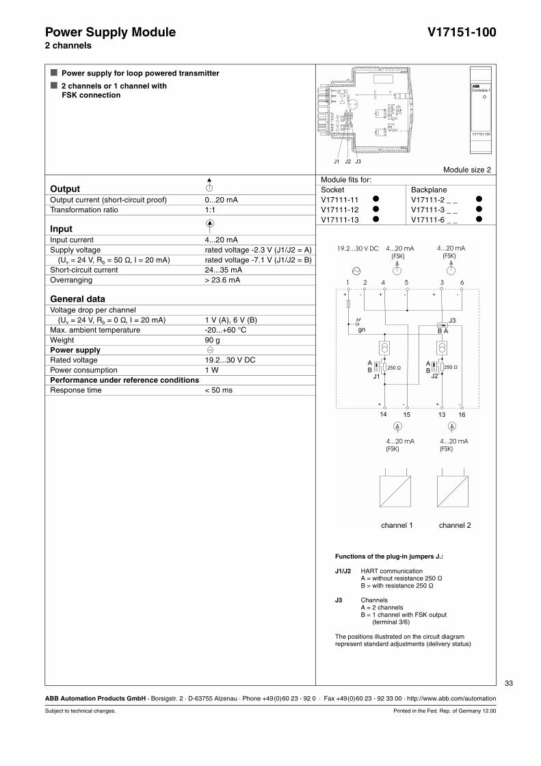
Power Supply Module V17151-1002 channels
Power supply for loop powered transmitter
2 channels or 1 channel withFSK connection
Module size 2Module fits for:
Output Socket BackplaneOutput current (short-circuit proof) 0...20 mA V17111-11 V17111-2 _ _
Transformation ratio 1:1 V17111-12 V17111-3 _ _
V17111-13 V17111-6 _ _
InputInput current 4...20 mASupply voltage rated voltage -2.3 V (J1/J2 = A)
(Uv = 24 V, Rb = 50 Ω, I = 20 mA) rated voltage -7.1 V (J1/J2 = B)Short-circuit current 24...35 mAOverranging > 23.6 mA
General dataVoltage drop per channel
(Uv = 24 V, Rb = 0 Ω, I = 20 mA) 1 V (A), 6 V (B)Max. ambient temperature -20...+60 °CWeight 90 gPower supplyRated voltage 19.2...30 V DCPower consumption 1 WPerformance under reference conditionsResponse time < 50 ms
Functions of the plug-in jumpers J.:
J1/J2 HART communicationA = without resistance 250 Ω B = with resistance 250 Ω
J3 ChannelsA = 2 channelsB = 1 channel with FSK outputB = (terminal 3/6)
The positions illustrated on the circuit diagramrepresent standard adjustments (delivery status)
15 1614
J1
250 Ω 250 ΩAB
AB
B A
J2
J3
gn
13
4...20 mA 4...20 mA(FSK) (FSK)
5 64 321
(FSK) (FSK)
+
+ +
+
+
-
- -
-
-
channel 1 channel 2
19.2...30 V DC 4...20 mA 4...20 mA
34
ABB Automation Products GmbH · Borsigstr. 2 · D-63755 Alzenau · Phone +49(0)60 23 - 92 0 · Fax +49(0)60 23 - 92 33 00 · http://www.abb.com/automation
Subject to technical changes. Printed in the Fed. Rep. of Germany 12.00
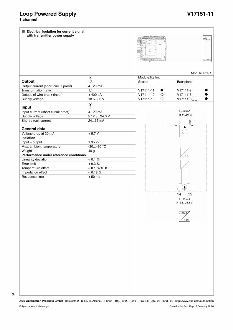
Loop Powered Supply V17151-111 channel
Electrical isolation for current signalwith transmitter power supply
Module size 1Module fits for:
Output Socket BackplaneOutput current (short-circuit proof) 4...20 mATransformation ratio 1:1 V17111-11 V17111-2 _ _
Detect. of wire break (input) < 400 µA V17111-12 V17111-3 _ _
Supply voltage 18.5...30 V V17111-13 V17111-6 _ _
InputInput current (short-circuit proof) 4...20 mASupply voltage ≥ 12.8...24.3 VShort-circuit current 24...35 mA
General dataVoltage drop at 20 mA < 5.7 VIsolationInput – output 1.35 kVMax. ambient temperature -20...+60 °CWeight 40 gPerformance under reference conditionsLinearity deviation < 0.1 %Error limit < 0.3 %Temperature effect < 0.1 %/10 KImpedance effect < 0.18 %Response time < 50 ms
P, dP, T
4...20 mA
+ -
-+
4 5
1514
4...20 mA
4...20 mA
(18.5...30 V)
(>12.8...24.3 V)
35
ABB Automation Products GmbH · Borsigstr. 2 · D-63755 Alzenau · Phone +49(0)60 23 - 92 0 · Fax +49(0)60 23 - 92 33 00 · http://www.abb.com/automation
Subject to technical changes. Printed in the Fed. Rep. of Germany 12.00
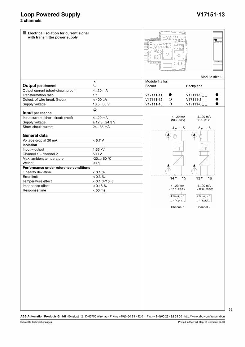
Loop Powered Supply V17151-132 channels
Electrical isolation for current signalwith transmitter power supply
Module size 2Module fits for:
Output per channel Socket BackplaneOutput current (short-circuit proof) 4...20 mATransformation ratio 1:1 V17111-11 V17111-2 _ _
Detect. of wire break (input) < 400 µA V17111-12 V17111-3 _ _
Supply voltage 18.5...30 V V17111-13 V17111-6 _ _
Input per channelInput current (short-circuit proof) 4...20 mASupply voltage ≥ 12.8...24.3 VShort-circuit current 24...35 mA
General dataVoltage drop at 20 mA < 5.7 VIsolationInput – output 1.35 kVChannel 1 – channel 2 500 VMax. ambient temperature -20...+60 °CWeight 90 gPerformance under reference conditionsLinearity deviation < 0.1 %Error limit < 0.3 %Temperature effect < 0.1 %/10 KImpedance effect < 0.18 %Response time < 50 ms
- -+ +5 64 3
4...20 mA
4...20 mA 4...20 mA
4...20 mA
+ +- -15 1614 13
P, dP, T, … P, dP, T, …
4...20 mA 4...20 mA
> 12.8...23.3 V > 12.8...23.3 V
Channel 1 Channel 2
(18.5...30 V) (18.5...30 V)

36
ABB Automation Products GmbH · Borsigstr. 2 · D-63755 Alzenau · Phone +49(0)60 23 - 92 0 · Fax +49(0)60 23 - 92 33 00 · http://www.abb.com/automation
Subject to technical changes. Printed in the Fed. Rep. of Germany 12.00

37
ABB Automation Products GmbH · Borsigstr. 2 · D-63755 Alzenau · Phone +49(0)60 23 - 92 0 · Fax +49(0)60 23 - 92 33 00 · http://www.abb.com/automation
Subject to technical changes. Printed in the Fed. Rep. of Germany 12.00
Isolating Power Supply V17151-21_1 channel
Power supply for loop powered transmitters
Isolating driver for 4...20 mA
Wire break monitoring output overrange/underrange(Jumper J1)
Module size 2Module fits for:
Output Socket BackplaneTransformation ratio 1:1 V17111-11 V17111-2 _ _
Residual ripple (peak-to-peak) < 0.25 % V17111-12 V17111-3 _ _
Output signal short-circuit proof V17111-13 V17111-6 _ _
Type Signal Wire break Short-circuit LoadV17151-210 4...20 mA < 0.1 > 22 mA 23...30 mA 0...600 ΩV17151-211 0...20 mA 0 > 22 mA 23...30 mA 0...600 ΩV17151-212 0...10 V 0 > 11 V – > 10 kΩV17151-213 0... 5 mA 0 > 5.13 mA – 0...2.4 kΩ
InputInput current 4...20 mAShort circuit current 23...30 mAResidual ripple (peak-to-peak) < 100 mVIsolating power supply (terminal 14/15)Supply voltage at 22.7 mA ≥ 14 VIsolating driver (terminal 13/16)Voltage drop < 1 V
General dataLED indicators, power “On“ (green)IsolationInput – output/power supply 2.3 kVMax. ambient temperature -20...+60 °CWeight 90 gPower supplyRated voltage 19.2...30 V DCPower consumption 1.05 WPerformance under reference conditionsLinearity deviation < 0.1 %Error limit < 0.25 %Temperature effect < 0.1 %/10 KImpedance effect < 0.05 %Response time < 50 ms
0... 5 mA0...10 V0...20 mA4...20 mA
0
4...20 mA4...20 mA(14 V)
1 2 4 5 3 6
16
J1
131514
BA
gn
+ - + -
+ - + -
19.2...30 V DC
Functions of the plug-in jumpers J.:
J1 Wire break monitoringA = withoutB = with
The positions illustrated on the circuit diagramrepresent standard adjustments (delivery status)

38
ABB Automation Products GmbH · Borsigstr. 2 · D-63755 Alzenau · Phone +49(0)60 23 - 92 0 · Fax +49(0)60 23 - 92 33 00 · http://www.abb.com/automation
Subject to technical changes. Printed in the Fed. Rep. of Germany 12.00
Isolating Power Supply V17151-21_1 channel
Ordering information Catalog No.Isolating Power supply, 1 channel V17151-21_Output 4...20 mA 0
0...20 mA 10...10 V 20...5 mA 3
39
ABB Automation Products GmbH · Borsigstr. 2 · D-63755 Alzenau · Phone +49(0)60 23 - 92 0 · Fax +49(0)60 23 - 92 33 00 · http://www.abb.com/automation
Subject to technical changes. Printed in the Fed. Rep. of Germany 12.00
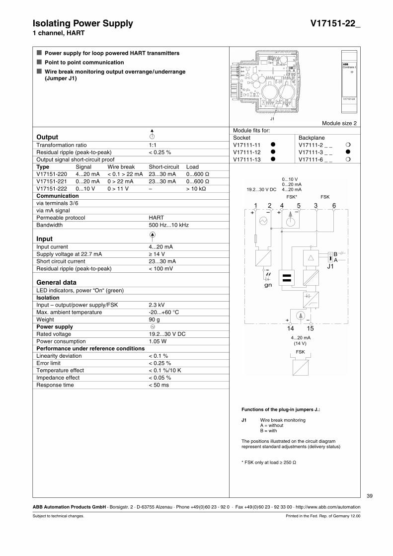
Isolating Power Supply V17151-22_1 channel, HART
Power supply for loop powered HART transmitters
Point to point communication
Wire break monitoring output overrange/underrange(Jumper J1)
Module size 2Module fits for:
Output Socket BackplaneTransformation ratio 1:1 V17111-11 V17111-2 _ _
Residual ripple (peak-to-peak) < 0.25 % V17111-12 V17111-3 _ _
Output signal short-circuit proof V17111-13 V17111-6 _ _
Type Signal Wire break Short-circuit LoadV17151-220 4...20 mA < 0.1 > 22 mA 23...30 mA 0...600 ΩV17151-221 0...20 mA 0 > 22 mA 23...30 mA 0...600 ΩV17151-222 0...10 V 0 > 11 V – > 10 kΩCommunicationvia terminals 3/6via mA signalPermeable protocol HARTBandwidth 500 Hz...10 kHz
InputInput current 4...20 mASupply voltage at 22.7 mA ≥ 14 VShort circuit current 23...30 mAResidual ripple (peak-to-peak) < 100 mV
General dataLED indicators, power “On“ (green)IsolationInput – output/power supply/FSK 2.3 kVMax. ambient temperature -20...+60 °CWeight 90 gPower supplyRated voltage 19.2...30 V DCPower consumption 1.05 WPerformance under reference conditionsLinearity deviation < 0.1 %Error limit < 0.25 %Temperature effect < 0.1 %/10 KImpedance effect < 0.05 %Response time < 50 ms
BA
gn
+ - + -
+ -
0...10 V0...20 mA4...20 mA
FSK
FSK* FSK
4...20 mA
(14 V)
1 2 4 5 3 6
J1
1514
19.2...30 V DC
Functions of the plug-in jumpers J.:
J1 Wire break monitoringA = withoutB = with
The positions illustrated on the circuit diagramrepresent standard adjustments (delivery status)
* FSK only at load ≥ 250 Ω
40
ABB Automation Products GmbH · Borsigstr. 2 · D-63755 Alzenau · Phone +49(0)60 23 - 92 0 · Fax +49(0)60 23 - 92 33 00 · http://www.abb.com/automation
Subject to technical changes. Printed in the Fed. Rep. of Germany 12.00
Isolating Power Supply V17151-22_1 channel, HART
Ordering information Catalog No.Isolating Power Supply, 1 channel, HART V17151-22_Output 4...20 mA 0
0...20 mA 10...10 V 2
41
ABB Automation Products GmbH · Borsigstr. 2 · D-63755 Alzenau · Phone +49(0)60 23 - 92 0 · Fax +49(0)60 23 - 92 33 00 · http://www.abb.com/automation
Subject to technical changes. Printed in the Fed. Rep. of Germany 12.00
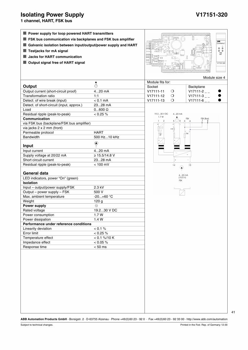
Isolating Power Supply V17151-3201 channel, HART, FSK bus
Power supply for loop powered HART transmitters
FSK bus communication via backplanes and FSK bus amplifier
Galvanic isolation between input/output/power supply and HART
Testjacks for mA signal
Jacks for HART communication
Output signal free of HART signal
Module size 4Module fits for:
Output Socket BackplaneOutput current (short-circuit proof) 4...20 mA V17111-11 V17111-2 _ _
Transformation ratio 1:1 V17111-12 V17111-3 _ _
Detect. of wire break (input) < 0.1 mA V17111-13 V17111-6 _ _
Detect. of short-circuit (input, approx.) 23...28 mALoad 0...600 ΩResidual ripple (peak-to-peak) < 0.25 %Communicationvia FSK bus (backplane/FSK bus amplifier)via jacks 2 x 2 mm (front)Permeable protocol HARTBandwidth 500 Hz...10 kHz
InputInput current 4...20 mASupply voltage at 20/22 mA ≥ 15.5/14.8 VShort circuit current 23...28 mAResidual ripple (peak-to-peak) < 100 mV
General dataLED indicators, power “On“ (green)IsolationInput – output/power supply/FSK 2.3 kVOutput – power supply – FSK 500 VMax. ambient temperature -20...+60 °CWeight 120 gPower supplyRated voltage 19.2...30 V DCPower consumption 1.7 WPower dissipation 1.4 WPerformance under reference conditionsLinearity deviation < 0.1 %Error limit < 0.25 %Temperature effect < 0.1 %/10 KImpedance effect < 0.05 %Response time < 50 ms
7
15
8635421
+
14
-
+ -
+ -
FSKgn
-
mA
-
-
19.2...30 V DC
1.7 W
4...20 mA(15.5 V)
FSK
4...20 mA
FSK (Bus)FSK
42
ABB Automation Products GmbH · Borsigstr. 2 · D-63755 Alzenau · Phone +49(0)60 23 - 92 0 · Fax +49(0)60 23 - 92 33 00 · http://www.abb.com/automation
Subject to technical changes. Printed in the Fed. Rep. of Germany 12.00
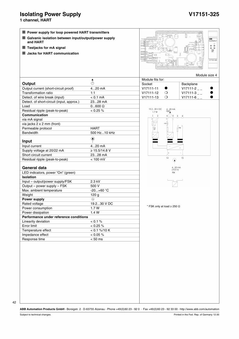
Isolating Power Supply V17151-3251 channel, HART
Power supply for loop powered HART transmitters
Galvanic isolation between input/output/power supply and HART
Testjacks for mA signal
Jacks for HART communication
Module size 4Module fits for:
Output Socket BackplaneOutput current (short-circuit proof) 4...20 mA V17111-11 V17111-2 _ _
Transformation ratio 1:1 V17111-12 V17111-3 _ _
Detect. of wire break (input) < 0.1 mA V17111-13 V17111-6 _ _
Detect. of short-circuit (input, approx.) 23...28 mALoad 0...600 ΩResidual ripple (peak-to-peak) < 0.25 %Communicationvia mA signalvia jacks 2 x 2 mm (front)Permeable protocol HARTBandwidth 500 Hz...10 kHz
InputInput current 4...20 mASupply voltage at 20/22 mA ≥ 15.5/14.8 VShort circuit current 23...28 mAResidual ripple (peak-to-peak) < 100 mV
General dataLED indicators, power “On“ (green)IsolationInput – output/power supply/FSK 2.3 kVOutput – power supply – FSK 500 VMax. ambient temperature -20...+60 °CWeight 120 gPower supplyRated voltage 19.2...30 V DCPower consumption 1.7 WPower dissipation 1.4 WPerformance under reference conditionsLinearity deviation < 0.1 %Error limit < 0.25 %Temperature effect < 0.1 %/10 KImpedance effect < 0.05 %Response time < 50 ms
15
635421
+
14
-
+ -
+ -
FSKgn
-
mA
-
-
19.2...30 V DC
1.7 W
4...20 mA(15.5 V)
FSK
4...20 mAFSK*
* FSK only at load ≥ 250 Ω

43
ABB Automation Products GmbH · Borsigstr. 2 · D-63755 Alzenau · Phone +49(0)60 23 - 92 0 · Fax +49(0)60 23 - 92 33 00 · http://www.abb.com/automation
Subject to technical changes. Printed in the Fed. Rep. of Germany 12.00
Isolating Power Supply V17151-3402 channels, HART, FSK bus
Power supply for loop powered HART transmitters
FSK bus communication via backplanes and FSK bus amplifier
Galvanic isolation between input/output/power supply and HART
Jacks for HART communication
Output signal free of HART signal
Module size 4Module fits for:
Output per channel Socket BackplaneOutput current (short-circuit proof) 4...20 mA V17111-11 V17111-2 _ _
Transformation ratio 1:1 V17111-12 V17111-3 _ _
Detect. of wire break (input) < 0.1 mA V17111-13 V17111-6 _ _
Detect. of short-circuit (input, approx.) 23...28 mALoad 0...600 ΩResidual ripple (peak-to-peak) < 0.25 %Communication per channelvia FSK bus (backplane/FSK bus amplifier)via jacks 2 x 2 mm (front)Permeable protocol HARTBandwidth 500 Hz...10 kHz
Input per channelInput current 4...20 mASupply voltage at 20/22 mA ≥ 15.5/14.8 VShort circuit current 23...28 mAResidual ripple (peak-to-peak) < 100 mV
General dataLED indicators, power “On“ (green)Isolation per channelInput – output/power supply/FSK 2.3 kVOutput – power supply – FSK 500 VIsolation channel 1 – channel 2Input 1 – input 2 500 VOutput 1 – output 2 500 VMax. ambient temperature -20...+60 °CWeight 140 gPower supplyRated voltage 19.2...30 V DCPower consumption 3.1 WPower dissipation 2.45 WPerformance under reference conditionsLinearity deviation < 0.1 %Error limit < 0.25 %Temperature effect < 0.1 %/10 KImpedance effect < 0.05 %Response time < 50 ms
15 16
8 107 95 64 321
+ +
14 13
- -
+ +- -
+ -
211 2
FSK 1 FSK 2gn
- - -
- -
19.2...30 V DC
3.1 W
4...20 mA 4...20 mA(15.5 V) (15.5 V)
FSK FSK
4...20 mA 4...20 mA
FSK (Bus) FSK (Bus)
Channel 1 Channel 2
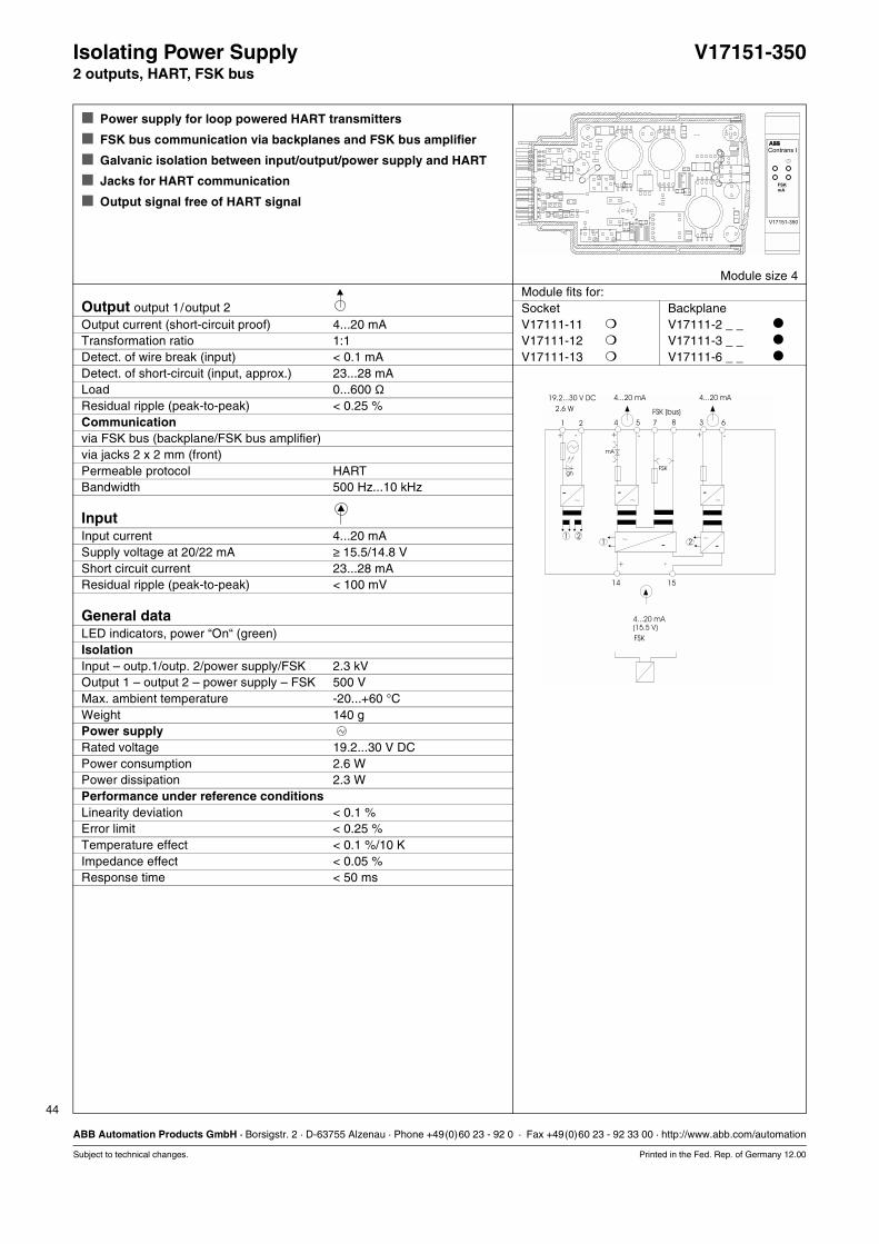
44
ABB Automation Products GmbH · Borsigstr. 2 · D-63755 Alzenau · Phone +49(0)60 23 - 92 0 · Fax +49(0)60 23 - 92 33 00 · http://www.abb.com/automation
Subject to technical changes. Printed in the Fed. Rep. of Germany 12.00
Isolating Power Supply V17151-3502 outputs, HART, FSK bus
Power supply for loop powered HART transmitters
FSK bus communication via backplanes and FSK bus amplifier
Galvanic isolation between input/output/power supply and HART
Jacks for HART communication
Output signal free of HART signal
Module size 4Module fits for:
Output output 1/output 2 Socket BackplaneOutput current (short-circuit proof) 4...20 mA V17111-11 V17111-2 _ _
Transformation ratio 1:1 V17111-12 V17111-3 _ _
Detect. of wire break (input) < 0.1 mA V17111-13 V17111-6 _ _
Detect. of short-circuit (input, approx.) 23...28 mALoad 0...600 ΩResidual ripple (peak-to-peak) < 0.25 %Communicationvia FSK bus (backplane/FSK bus amplifier)via jacks 2 x 2 mm (front)Permeable protocol HARTBandwidth 500 Hz...10 kHz
InputInput current 4...20 mASupply voltage at 20/22 mA ≥ 15.5/14.8 VShort circuit current 23...28 mAResidual ripple (peak-to-peak) < 100 mV
General dataLED indicators, power “On“ (green)IsolationInput – outp.1/outp. 2/power supply/FSK 2.3 kVOutput 1 – output 2 – power supply – FSK 500 VMax. ambient temperature -20...+60 °CWeight 140 gPower supplyRated voltage 19.2...30 V DCPower consumption 2.6 WPower dissipation 2.3 WPerformance under reference conditionsLinearity deviation < 0.1 %Error limit < 0.25 %Temperature effect < 0.1 %/10 KImpedance effect < 0.05 %Response time < 50 ms
15
21
14
+ -
+ -
211 2
gn
-
-
5 7 84
+ -
FSK
mA
-
63
+ -
-
-
19.2...30 V DC
2.6 W
4...20 mA(15.5 V)
FSK
4...20 mA
FSK (bus)
4...20 mA
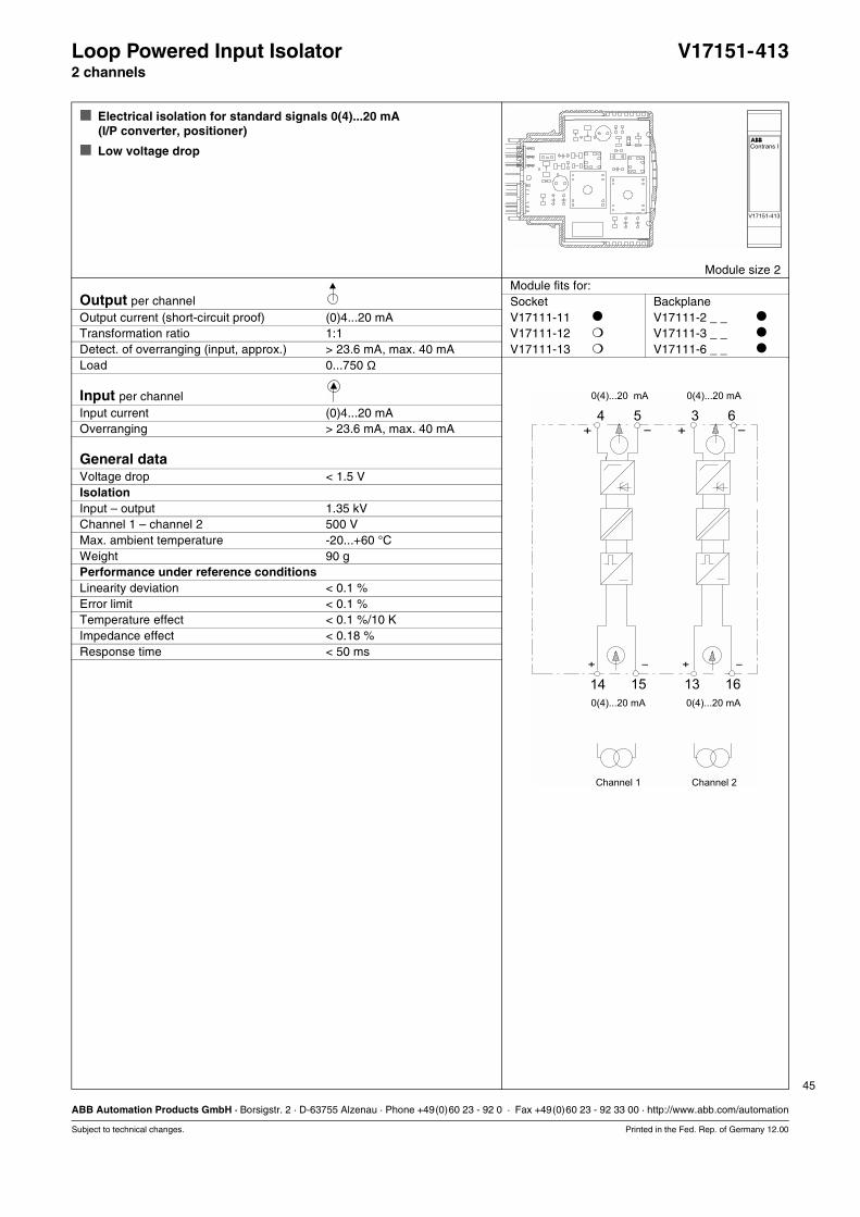
45
ABB Automation Products GmbH · Borsigstr. 2 · D-63755 Alzenau · Phone +49(0)60 23 - 92 0 · Fax +49(0)60 23 - 92 33 00 · http://www.abb.com/automation
Subject to technical changes. Printed in the Fed. Rep. of Germany 12.00
Loop Powered Input Isolator V17151-4132 channels
Electrical isolation for standard signals 0(4)...20 mA(I/P converter, positioner)
Low voltage drop
Module size 2Module fits for:
Output per channel Socket BackplaneOutput current (short-circuit proof) (0)4...20 mA V17111-11 V17111-2 _ _
Transformation ratio 1:1 V17111-12 V17111-3 _ _
Detect. of overranging (input, approx.) > 23.6 mA, max. 40 mA V17111-13 V17111-6 _ _
Load 0...750 Ω
Input per channelInput current (0)4...20 mAOverranging > 23.6 mA, max. 40 mA
General dataVoltage drop < 1.5 VIsolationInput – output 1.35 kVChannel 1 – channel 2 500 VMax. ambient temperature -20...+60 °CWeight 90 gPerformance under reference conditionsLinearity deviation < 0.1 %Error limit < 0.1 %Temperature effect < 0.1 %/10 KImpedance effect < 0.18 %Response time < 50 ms
0(4)...20 mA 0(4)...20 mA
0(4)...20 mA 0(4)...20 mA
+ +- -
- -+ +
4 35 6
15 1614 13
Channel 1 Channel 2
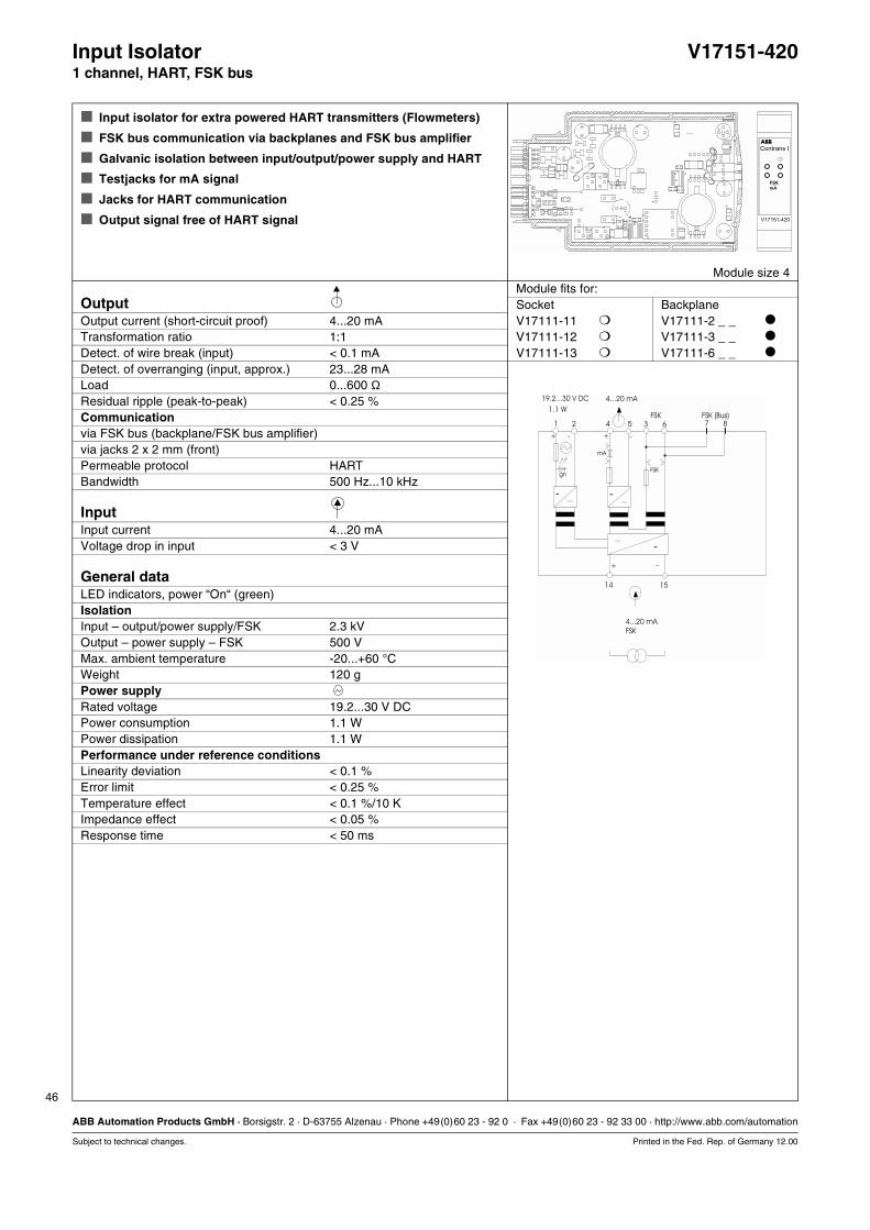
46
ABB Automation Products GmbH · Borsigstr. 2 · D-63755 Alzenau · Phone +49(0)60 23 - 92 0 · Fax +49(0)60 23 - 92 33 00 · http://www.abb.com/automation
Subject to technical changes. Printed in the Fed. Rep. of Germany 12.00
Input Isolator V17151-4201 channel, HART, FSK bus
Input isolator for extra powered HART transmitters (Flowmeters)
FSK bus communication via backplanes and FSK bus amplifier
Galvanic isolation between input/output/power supply and HART
Testjacks for mA signal
Jacks for HART communication
Output signal free of HART signal
Module size 4Module fits for:
Output Socket BackplaneOutput current (short-circuit proof) 4...20 mA V17111-11 V17111-2 _ _
Transformation ratio 1:1 V17111-12 V17111-3 _ _
Detect. of wire break (input) < 0.1 mA V17111-13 V17111-6 _ _
Detect. of overranging (input, approx.) 23...28 mALoad 0...600 ΩResidual ripple (peak-to-peak) < 0.25 %Communicationvia FSK bus (backplane/FSK bus amplifier)via jacks 2 x 2 mm (front)Permeable protocol HARTBandwidth 500 Hz...10 kHz
InputInput current 4...20 mAVoltage drop in input < 3 V
General dataLED indicators, power “On“ (green)IsolationInput – output/power supply/FSK 2.3 kVOutput – power supply – FSK 500 VMax. ambient temperature -20...+60 °CWeight 120 gPower supplyRated voltage 19.2...30 V DCPower consumption 1.1 WPower dissipation 1.1 WPerformance under reference conditionsLinearity deviation < 0.1 %Error limit < 0.25 %Temperature effect < 0.1 %/10 KImpedance effect < 0.05 %Response time < 50 ms
7
15
8635421
+
14
-
+ -
+ -
FSKgn
-
mA
-
-
19.2...30 V DC
1.1 W
4...20 mA
FSK
4...20 mA
FSK FSK (Bus)

47
ABB Automation Products GmbH · Borsigstr. 2 · D-63755 Alzenau · Phone +49(0)60 23 - 92 0 · Fax +49(0)60 23 - 92 33 00 · http://www.abb.com/automation
Subject to technical changes. Printed in the Fed. Rep. of Germany 12.00
Input Isolator, parameterizable V17151-43_1 channel V, mA
Input isolator for direct current or direct voltage signals
free adjustable measuring ranges
Definition of parameters via LCI interface(does not require an additional power supply)
Relay output for alarm
Module size2Module fits for:
Output (open and short-circuit proof) Socket BackplaneType Full modulation span Load V17111-11 V17111-2 _ _
V17151-430 0/4...20 mA (0/3.8...20,5 mA) 0...600 Ω V17111-12 V17111-3 _ _
V17151-432 0/2...10 V (0/1.9...10.25 V) > 100 kΩ V17111-13 V17111-6 _ _
V17151-433 0...5 mA (0...5.13 mA) 0...2.4 kΩV17151-434 0/1...5 V (0/0.95...5.13 V) > 50 kΩResidual ripple < 0.25 % (peak-to-peak)Damping 0...30 sBinary outputTriggering (adjustable via software) alarm set point, wire breakRelay contact (via jumper J1) 1 x NO/NCContact ratings 250VAC; 1A; cosϕ >0.7; 560VA
30V DC; 2 A; 60 W Parameterization via software
or customer-specific
Input (open and short-circuit proof)Sensors V, mAMeasuring ranges full modulat. span/load min. meas. span
-25...+25 mA/5 Ω 0.5 mA-12.5...+12.5 V/> 100 kΩ 300 mV
Customer specific (max. tie points) 60
General dataLED indicator power “On“ (green)
switching state relay (red)IsolationInput – output/power supply 2.3 kVMax. ambient temperature -20...+60 °CWeight 90 gPower supplyConnection terminals 1(+); 2(-)Rated voltage 19.2...30 V DCPower consumption approx. 1.0 WPerformance under reference conditionsLinearity deviation < 0.1 %Error limit < 0.1 %Temperature effect < 0.1 %/10 KImpedance effect < 0,05 % Response time < 250 ms
Functions of the plug-in jumpers J.:
J1 Relay outputA = NCB = NO
J2 Parameterizationdisableenable
The positions illustrated on the circuit diagramrepresent standard adjustments (delivery status)
4
14
5-
15
1
+
2
1316
3 6
-
-LKS
A/D
J2µC
J1BA
ro
µC
1211
+
+ +-
+25 ...-25 mA
1)
2)
0/4...20 mA0...5 mA0/2...10 V0/1...5 V
250 V AC, 1 A30 V DC, 2 A19.2...30 V DC
-12.5 ...+12.5 V
gn
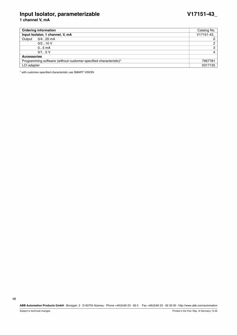
48
ABB Automation Products GmbH · Borsigstr. 2 · D-63755 Alzenau · Phone +49(0)60 23 - 92 0 · Fax +49(0)60 23 - 92 33 00 · http://www.abb.com/automation
Subject to technical changes. Printed in the Fed. Rep. of Germany 12.00
* with customer-specified characteristic use SMART VISION
Input Isolator, parameterizable V17151-43_1 channel V, mA
Ordering information Catalog No.Input Isolator, 1 channel, V, mA V17151-43_Output 0/4...20 mA 0
0/2...10 V 20...5 mA 30/1...5 V 4
AccessoriesProgramming software (without customer-specified characteristic)* 7957781LCI adapter 0317135
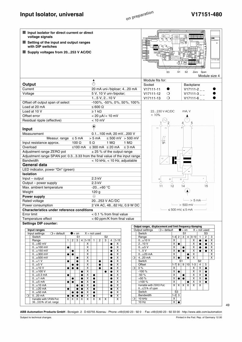
49
ABB Automation Products GmbH · Borsigstr. 2 · D-63755 Alzenau · Phone +49(0)60 23 - 92 0 · Fax +49(0)60 23 - 92 33 00 · http://www.abb.com/automation
Subject to technical changes. Printed in the Fed. Rep. of Germany 12.00
Input Isolator, universal V17151-480
Input isolator for direct current or directvoltage signals
Setting of the input and output rangeswith DIP switches
Supply voltages from 20...253 V AC/DC
Module size 4Module fits for:
Output Socket BackplaneCurrent 20 mA uni-/biploar; 4...20 mA V17111-11 V17111-2 _ _
Voltage 5 V, 10 V uni-/bipolar; V17111-12 V17111-3 _ _
1...5 V, 2...10 V V17111-13 V17111-6 _ _
Offset off output span of select -100%, -50%, 0%, 50%, 100%Load at 20 mA ≤ 600 ΩLoad at 10 V ≥=1 kΩOffset error < 20 µA/< 10 mVResidual ripple (effective) < 10 mV
InputMeasurement 0.1...100 mA; 20 mV...200 V
Measur. range ≤ 5 mA > 5 mA ≤ 500 mV > 500 mVInput resistance approx. 100 Ω 5 Ω 1 MΩ 1 MΩOverload ≤100 mA ≤ 300 mA ≤ 20 mA ≤ 3 mAAdjustment range ZERO pot ± 25 % of the output rangeAdjustment range SPAN pot: 0.3...3.33 from the final value of the input rangeBandwidth < 10 kHz, < 10 Hz, adjustableGeneral dataLED indicator, power “On“ (green)IsolationInput – output 2.3 kVOutput – power supply 2.3 kVMax. ambient temperature -20...+60 °CWeight 120 gPower supplyRated voltage 20...253 V AC/DCPower consumption 2 VA AC, 48...62 Hz, 0.9 W DCCharacteristics under reference conditionsError limit < 0.1 % from final valueTemperature effect < 60 ppm/K from final valueSettings DIP counter:
1512
5421
+
1411
-
++ + -
-
-
22...230 V AC/DC
± 10%
> 5 mA
> 500 mV
≤ 500 mV, 5 mA≤
gn
mA, V
Output ranges, displacement and limit frequency/dampingOutput settings = default = on X = not used
Switch S1 S3Range 1-4 2 3 4 8-10 1 2 30...±10 V X X X2...10 V X X X0...±5 V X X X1...5 V X X X0...±20 mA X X X
4...20 mA X X XSwitch S1 S2Offset 1-7 8 9 10 1-3 4 5
0 % X X X
-100 % X X X
-50 % X X X
+50 % X X X
+100 % X X X
Variable with ZERO Pot:0...±25% of span
X X X X X X
Switch S3Bandwidth 1-2 3
10 kHz X10 Hz X
on preparation
Input rangesInput settings = default = on X = not used
Switch S1 S2Range 1 2 3 4 5-10 1 2 3 4 5-100...±60 mV X X0...±100 mV X X0...±150 mV X X0...±300 mV X X0...±500 mV X X0...±1 V X X0...±5 V X X0...±10 V X X0...±100 V X X0...±0.3 mA X X0...±1 mA X X0...±5 mA X X0...±10 mA X X0...±20 mA X X0...±50 mA X X
0...20 mA X XVariable with SPAN Pot:30...333% of sel. range
X X X X X X X X X

50
ABB Automation Products GmbH · Borsigstr. 2 · D-63755 Alzenau · Phone +49(0)60 23 - 92 0 · Fax +49(0)60 23 - 92 33 00 · http://www.abb.com/automation
Subject to technical changes. Printed in the Fed. Rep. of Germany 12.00
Loop Powered Supply Ex V17151-511 channel
Electrical isolation for current signals with transmitter power supply
Module size 2Module fits for:
Output (safe area) Socket BackplaneOutput current (short-circuit proof) 4...20 mA V17111-11 V17111-2 _ _
Transformation ratio 1:1 V17111-12 V17111-3 _ _
Detect. of wire break (input) < 400 µA V17111-13 V17111-6 _ _
Supply voltage 18.5...30 V
Input (hazardous area)Input current (short-circuit proof) 4...20 mASupply voltage > 13.5 VShort-circuit current 23...30 mAExplosion protection [EEx ib] IICCertificate of conformity PTB No. 00 ATEX 2017Max. short-circuit current Io = 28.5 mAMax. voltage Uo = 20 VMax. power Po = 570 mWPermitted external inductance La = 1.3 mHPermitted external capacitance Ca = 95 nF
General dataIsolationInput – output 2.3 kVMax. ambient temperature -20...+60 °CWeight 90 gPerformance under reference conditionsLinearity deviation < 0.1 %Error limit < 0.25 %Temperature effect < 0.1 %/10 KImpedance effect < 0.05 %Response time < 50 ms
+ -
-+
4...20 mA
4...20 mA
4 5
1514
EEx ib
Hazardous area
(18.5...30 V)
( 13.5 V)≥
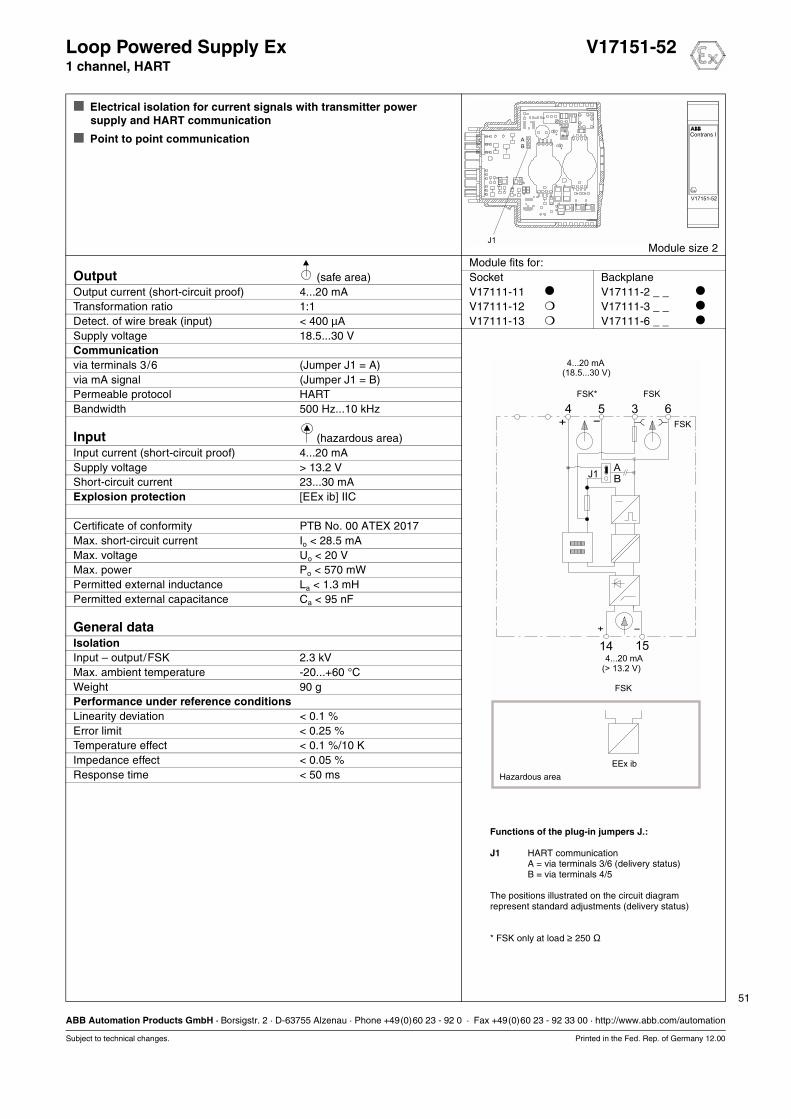
51
ABB Automation Products GmbH · Borsigstr. 2 · D-63755 Alzenau · Phone +49(0)60 23 - 92 0 · Fax +49(0)60 23 - 92 33 00 · http://www.abb.com/automation
Subject to technical changes. Printed in the Fed. Rep. of Germany 12.00
Loop Powered Supply Ex V17151-521 channel, HART
Electrical isolation for current signals with transmitter power supply and HART communication
Point to point communication
Module size 2Module fits for:
Output (safe area) Socket BackplaneOutput current (short-circuit proof) 4...20 mA V17111-11 V17111-2 _ _
Transformation ratio 1:1 V17111-12 V17111-3 _ _
Detect. of wire break (input) < 400 µA V17111-13 V17111-6 _ _
Supply voltage 18.5...30 VCommunicationvia terminals 3/6 (Jumper J1 = A)via mA signal (Jumper J1 = B)Permeable protocol HARTBandwidth 500 Hz...10 kHz
Input (hazardous area)Input current (short-circuit proof) 4...20 mASupply voltage > 13.2 VShort-circuit current 23...30 mAExplosion protection [EEx ib] IIC
Certificate of conformity PTB No. 00 ATEX 2017Max. short-circuit current Io < 28.5 mAMax. voltage Uo < 20 VMax. power Po < 570 mWPermitted external inductance La < 1.3 mHPermitted external capacitance Ca < 95 nF
General dataIsolationInput – output/FSK 2.3 kVMax. ambient temperature -20...+60 °CWeight 90 gPerformance under reference conditionsLinearity deviation < 0.1 %Error limit < 0.25 %Temperature effect < 0.1 %/10 KImpedance effect < 0.05 %Response time < 50 ms
+ -
-+
4...20 mA
FSK* FSK
4...20 mA
FSK
4 5 3 6
1514
EEx ib
J1BA
FSK
Hazardous area
(18.5...30 V)
(> 13.2 V)
Functions of the plug-in jumpers J.:
J1 HART communicationA = via terminals 3/6 (delivery status)B = via terminals 4/5
The positions illustrated on the circuit diagramrepresent standard adjustments (delivery status)
* FSK only at load ≥ 250 Ω

52
ABB Automation Products GmbH · Borsigstr. 2 · D-63755 Alzenau · Phone +49(0)60 23 - 92 0 · Fax +49(0)60 23 - 92 33 00 · http://www.abb.com/automation
Subject to technical changes. Printed in the Fed. Rep. of Germany 12.00
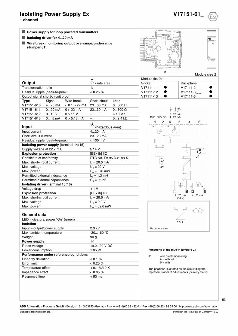
53
ABB Automation Products GmbH · Borsigstr. 2 · D-63755 Alzenau · Phone +49(0)60 23 - 92 0 · Fax +49(0)60 23 - 92 33 00 · http://www.abb.com/automation
Subject to technical changes. Printed in the Fed. Rep. of Germany 12.00
Isolating Power Supply Ex V17151-61_1 channel
Power supply for loop powered transmitters
Isolating driver for 4...20 mA
Wire break monitoring output overrange/underrange(Jumper J1)
Module size 2Module fits for:
Output (safe area) Socket BackplaneTransformation ratio 1:1 V17111-11 V17111-2 _ _
Residual ripple (peak-to-peak) < 0.25 % V17111-12 V17111-3 _ _
Output signal short-circuit proof V17111-13 V17111-6 _ _
Type Signal Wire break Short-circuit LoadV17151-610 4...20 mA < 0.1 > 22 mA 23...30 mA 0...600 ΩV17151-611 0...20 mA 0 > 22 mA 23...30 mA 0...600 ΩV17151-612 0...10 V 0 > 11 V – > 10 kΩV17151-613 0... 5 mA 0 > 5.13 mA – 0...2.4 kΩ
Input (hazardous area)Input current 4...20 mAShort circuit current 23...28 mAResidual ripple (peak-to-peak) < 100 mVIsolating power supply (terminal 14/15)Supply voltage at 22.7 mA ≥ 14 VExplosion protection [EEx ib] IICCertificate of conformity PTB No. Ex-95.D.2188 XMax. short-circuit current Io = 28.5 mAMax. voltage Uo = 20 VMax. power Po = 570 mWPermitted external inductance La = 1.3 mHPermitted external capacitance Ca = 95 nFIsolating driver (terminal 13/16)Voltage drop < 1 VExplosion protection [EEx ib] IICMax. short-circuit current Io = 28.5 mAMax. voltage Uo = 2.9 VMax. power Po = 82.6 mW
General dataLED indicators, power “On“ (green)IsolationInput – output/power supply 2.3 kVMax. ambient temperature -20...+60 °CWeight 90 gPower supplyRated voltage 19.2...30 V DCPower consumption 1.05 WPerformance under reference conditionsLinearity deviation < 0.1 %Error limit < 0.25 %Temperature effect < 0.1 %/10 KImpedance effect < 0.05 %Response time < 50 ms
0... 5 mA0...10 V0...20 mA4...20 mA
0
4...20 mA4...20 mA,(14 V)
1 2 4 5 3 6
16
J1
131514
BA
gn
+ - + -
+ - + -
EEx ib
19.2...30 V DC
Hazardous area
Functions of the plug-in jumpers J.:
J1 wire break monitoringA = withoutB = with
The positions illustrated on the circuit diagramrepresent standard adjustments (delivery status)

54
ABB Automation Products GmbH · Borsigstr. 2 · D-63755 Alzenau · Phone +49(0)60 23 - 92 0 · Fax +49(0)60 23 - 92 33 00 · http://www.abb.com/automation
Subject to technical changes. Printed in the Fed. Rep. of Germany 12.00
Isolating Power Supply Ex V17151-61_1 channel
Ordering information Catalog No.Isolating Power Supply Ex, 1 channel V17151-61_Output 4...20 mA 0
0...20 mA 10...10 V 20...5 mA 3
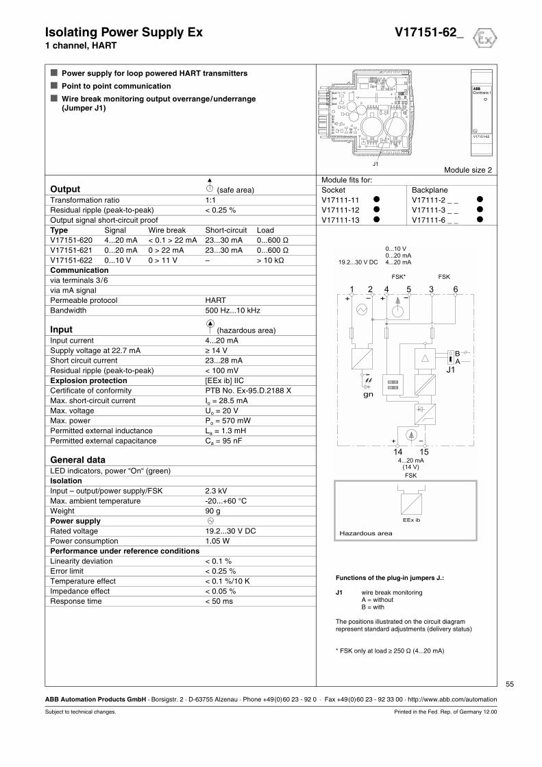
55
ABB Automation Products GmbH · Borsigstr. 2 · D-63755 Alzenau · Phone +49(0)60 23 - 92 0 · Fax +49(0)60 23 - 92 33 00 · http://www.abb.com/automation
Subject to technical changes. Printed in the Fed. Rep. of Germany 12.00
Isolating Power Supply Ex V17151-62_1 channel, HART
Power supply for loop powered HART transmitters
Point to point communication
Wire break monitoring output overrange/underrange(Jumper J1)
Module size 2Module fits for:
Output (safe area) Socket BackplaneTransformation ratio 1:1 V17111-11 V17111-2 _ _
Residual ripple (peak-to-peak) < 0.25 % V17111-12 V17111-3 _ _
Output signal short-circuit proof V17111-13 V17111-6 _ _
Type Signal Wire break Short-circuit LoadV17151-620 4...20 mA < 0.1 > 22 mA 23...30 mA 0...600 ΩV17151-621 0...20 mA 0 > 22 mA 23...30 mA 0...600 ΩV17151-622 0...10 V 0 > 11 V – > 10 kΩCommunicationvia terminals 3/6via mA signalPermeable protocol HARTBandwidth 500 Hz...10 kHz
Input (hazardous area)Input current 4...20 mASupply voltage at 22.7 mA ≥ 14 VShort circuit current 23...28 mAResidual ripple (peak-to-peak) < 100 mVExplosion protection [EEx ib] IICCertificate of conformity PTB No. Ex-95.D.2188 XMax. short-circuit current Io = 28.5 mAMax. voltage Uo = 20 VMax. power Po = 570 mWPermitted external inductance La = 1.3 mHPermitted external capacitance Ca = 95 nF
General dataLED indicators, power “On“ (green)IsolationInput – output/power supply/FSK 2.3 kVMax. ambient temperature -20...+60 °CWeight 90 gPower supplyRated voltage 19.2...30 V DCPower consumption 1.05 WPerformance under reference conditionsLinearity deviation < 0.1 %Error limit < 0.25 %Temperature effect < 0.1 %/10 KImpedance effect < 0.05 %Response time < 50 ms
BA
gn
+ - + -
+ -
0...10 V0...20 mA4...20 mA
FSK* FSK
4...20 mA(14 V)
FSK
1 2 4 5 3 6
J1
1514
EEx ib
Hazardous area
19.2...30 V DC
Functions of the plug-in jumpers J.:
J1 wire break monitoringA = withoutB = with
The positions illustrated on the circuit diagramrepresent standard adjustments (delivery status)
* FSK only at load ≥ 250 Ω (4...20 mA)

56
ABB Automation Products GmbH · Borsigstr. 2 · D-63755 Alzenau · Phone +49(0)60 23 - 92 0 · Fax +49(0)60 23 - 92 33 00 · http://www.abb.com/automation
Subject to technical changes. Printed in the Fed. Rep. of Germany 12.00
Isolating Power Supply Ex V17151-62_1 channel, HART
Ordering information Catalog No.Isolating Power Supply Ex, 1 channel, HART V17151-62_Output 4...20 mA 0
0...20 mA 10...10 V 2

57
ABB Automation Products GmbH · Borsigstr. 2 · D-63755 Alzenau · Phone +49(0)60 23 - 92 0 · Fax +49(0)60 23 - 92 33 00 · http://www.abb.com/automation
Subject to technical changes. Printed in the Fed. Rep. of Germany 12.00
Isolating Power Supply Ex V17151-7201 channel, HART, FSK bus
Power supply for loop powered HART transmitters
FSK bus communication via backplanes and FSK bus amplifier
Galvanic isolation between input/output/power supply and HART
Testjacks for mA signal
Jacks for HART communication
Output signal free of HART signal
Module size 4Module fits for:
Output (safe area) Socket BackplaneOutput current (short-circuit proof) 4...20 mA V17111-11 V17111-2 _ _
Transformation ratio 1:1 V17111-12 V17111-3 _ _
Detect. of wire break (input) < 0.1 mA V17111-13 V17111-6 _ _
Detect. of short-circuit (input, approx.) 23...28 mALoad 0...600 ΩResidual ripple (peak-to-peak) < 0.25 %Communicationvia FSK bus (backplane/FSK bus amplifier)via jacks 2 x 2 mm (front)Permeable protocol HARTBandwidth 500 Hz...10 kHz
Input (hazardous area)Input current 4...20 mASupply voltage at 20/22 mA ≥ 15.5/14.8 VShort circuit current 23...28 mAResidual ripple (peak-to-peak) < 100 mVExplosion protection [EEx ia] IICCertificate of conformity PTB 98 ATEX 2183 XMax. short-circuit current Io = 93 mAMax. voltage Uo = 26.3 VMax. power Po = 610 mWPermitted external inductance La = 4.1 mHPermitted external capacitance Ca = 97 nF
General dataLED indicators, power “On“ (green)IsolationInput – output/power supply/FSK 2.3 kVOutput – power supply – FSK 500 VMax. ambient temperature -20...+60 °CWeight 120 gPower supplyRated voltage 19.2...30 V DCPower consumption 1.7 WPower dissipation 1.4 WPerformance under reference conditionsLinearity deviation < 0.1 %Error limit < 0.25 %Temperature effect < 0.1 %/10 KImpedance effect < 0.05 %Response time < 50 ms
7
15
8635421
+
14
-
+ -
+ -
EEx ia
FSKgn
-
mA
-
-
19.2...30 V DC
1.7 W
4...20 mA(15,5 V)
FSK
4...20 mA
FSK (Bus)
Hazardous area
FSK
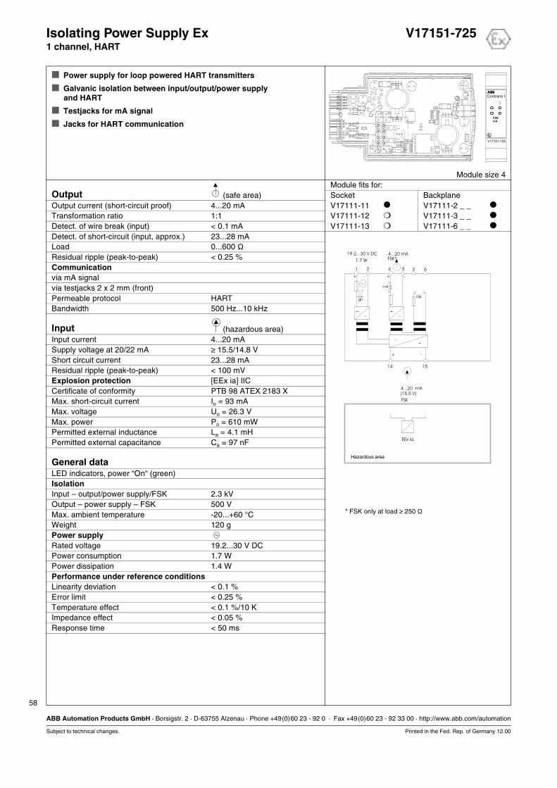
58
ABB Automation Products GmbH · Borsigstr. 2 · D-63755 Alzenau · Phone +49(0)60 23 - 92 0 · Fax +49(0)60 23 - 92 33 00 · http://www.abb.com/automation
Subject to technical changes. Printed in the Fed. Rep. of Germany 12.00
Isolating Power Supply Ex V17151-7251 channel, HART
Power supply for loop powered HART transmitters
Galvanic isolation between input/output/power supply and HART
Testjacks for mA signal
Jacks for HART communication
Module size 4Module fits for:
Output (safe area) Socket BackplaneOutput current (short-circuit proof) 4...20 mA V17111-11 V17111-2 _ _
Transformation ratio 1:1 V17111-12 V17111-3 _ _
Detect. of wire break (input) < 0.1 mA V17111-13 V17111-6 _ _
Detect. of short-circuit (input, approx.) 23...28 mALoad 0...600 ΩResidual ripple (peak-to-peak) < 0.25 %Communicationvia mA signalvia testjacks 2 x 2 mm (front)Permeable protocol HARTBandwidth 500 Hz...10 kHz
Input (hazardous area)Input current 4...20 mASupply voltage at 20/22 mA ≥ 15.5/14.8 VShort circuit current 23...28 mAResidual ripple (peak-to-peak) < 100 mVExplosion protection [EEx ia] IICCertificate of conformity PTB 98 ATEX 2183 XMax. short-circuit current Io = 93 mAMax. voltage Uo = 26.3 VMax. power Po = 610 mWPermitted external inductance La = 4.1 mHPermitted external capacitance Ca = 97 nF
General dataLED indicators, power “On“ (green)IsolationInput – output/power supply/FSK 2.3 kVOutput – power supply – FSK 500 VMax. ambient temperature -20...+60 °CWeight 120 gPower supplyRated voltage 19.2...30 V DCPower consumption 1.7 WPower dissipation 1.4 WPerformance under reference conditionsLinearity deviation < 0.1 %Error limit < 0.25 %Temperature effect < 0.1 %/10 KImpedance effect < 0.05 %Response time < 50 ms
15
635421
+
14
-
+ -
+ -
EEx ia
FSKgn
-
mA
-
-
19.2...30 V DC
1.7 W
4...20 mA
(15.5 V)
FSK
4...20 mAFSK*
Hazardous area
* FSK only at load ≥ 250 Ω
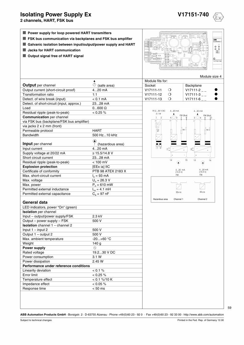
59
ABB Automation Products GmbH · Borsigstr. 2 · D-63755 Alzenau · Phone +49(0)60 23 - 92 0 · Fax +49(0)60 23 - 92 33 00 · http://www.abb.com/automation
Subject to technical changes. Printed in the Fed. Rep. of Germany 12.00
Isolating Power Supply Ex V17151-7402 channels, HART, FSK bus
Power supply for loop powered HART transmitters
FSK bus communication via backplanes and FSK bus amplifier
Galvanic isolation between input/output/power supply and HART
Jacks for HART communication
Output signal free of HART signal
Module size 4Module fits for:
Output per channel (safe area) Socket BackplaneOutput current (short-circuit proof) 4...20 mA V17111-11 V17111-2 _ _
Transformation ratio 1:1 V17111-12 V17111-3 _ _
Detect. of wire break (input) < 0.1 mA V17111-13 V17111-6 _ _
Detect. of short-circuit (input, approx.) 23...28 mALoad 0...600 ΩResidual ripple (peak-to-peak) < 0.25 %Communication per channelvia FSK bus (backplane/FSK bus amplifier)via jacks 2 x 2 mm (front)Permeable protocol HARTBandwidth 500 Hz...10 kHz
Input per channel (hazardous area)Input current 4...20 mASupply voltage at 20/22 mA ≥ 15.5/14.8 VShort circuit current 23...28 mAResidual ripple (peak-to-peak) < 100 mVExplosion protection [EEx ia] IICCertificate of conformity PTB 98 ATEX 2183 XMax. short-circuit current Io = 93 mAMax. voltage Uo = 26.3 VMax. power Po = 610 mWPermitted external inductance La = 4.1 mHPermitted external capacitance Ca = 97 nF
General dataLED indicators, power “On“ (green)Isolation per channelInput – output/power supply/FSK 2.3 kVOutput – power supply – FSK 500 VIsolation channel 1 – channel 2Input 1 – input 2 500 VOutput 1 – output 2 500 VMax. ambient temperature -20...+60 °CWeight 140 gPower supplyRated voltage 19.2...30 V DCPower consumption 3.1 WPower dissipation 2.45 WPerformance under reference conditionsLinearity deviation < 0.1 %Error limit < 0.25 %Temperature effect < 0.1 %/10 KImpedance effect < 0.05 %Response time < 50 ms
15 16
8 107 95 64 321
+ +
14 13
- -
+ +- -
+ -
211 2
EEx ia EEx ia
FSK 1 FSK 2gn
- - -
- -
19.2...30 V DC
3.1 W
4...20 mA 4...20 mA(15.5 V) (15.5 V)
FSK FSK
4...20 mA 4...20 mA
FSK (Bus) FSK (Bus)
Hazardous area Channel 1 Channel 2
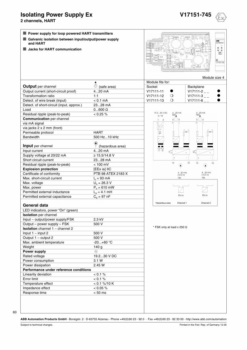
60
ABB Automation Products GmbH · Borsigstr. 2 · D-63755 Alzenau · Phone +49(0)60 23 - 92 0 · Fax +49(0)60 23 - 92 33 00 · http://www.abb.com/automation
Subject to technical changes. Printed in the Fed. Rep. of Germany 12.00
Isolating Power Supply Ex V17151-7452 channels, HART
Power supply for loop powered HART transmitters
Galvanic isolation between input/output/power supplyand HART
Jacks for HART communication
Module size 4Module fits for:
Output per channel (safe area) Socket BackplaneOutput current (short-circuit proof) 4...20 mA V17111-11 V17111-2 _ _
Transformation ratio 1:1 V17111-12 V17111-3 _ _
Detect. of wire break (input) < 0.1 mA V17111-13 V17111-6 _ _
Detect. of short-circuit (input, approx.) 23...28 mALoad 0...600 ΩResidual ripple (peak-to-peak) < 0.25 %Communication per channelvia mA signalvia jacks 2 x 2 mm (front)Permeable protocol HARTBandwidth 500 Hz...10 kHz
Input per channel (hazardous area)Input current 4...20 mASupply voltage at 20/22 mA ≥ 15.5/14.8 VShort circuit current 23...28 mAResidual ripple (peak-to-peak) < 100 mVExplosion protection [EEx ia] IICCertificate of conformity PTB 98 ATEX 2183 XMax. short-circuit current Io = 93 mAMax. voltage Uo = 26.3 VMax. power Po = 610 mWPermitted external inductance La = 4.1 mHPermitted external capacitance Ca = 97 nF
General dataLED indicators, power “On“ (green)Isolation per channelInput – output/power supply/FSK 2.3 kVOutput – power supply – FSK 500 VIsolation channel 1 – channel 2Input 1 – input 2 500 VOutput 1 – output 2 500 VMax. ambient temperature -20...+60 °CWeight 140 gPower supplyRated voltage 19.2...30 V DCPower consumption 3.1 WPower dissipation 2.45 WPerformance under reference conditionsLinearity deviation < 0.1 %Error limit < 0.1 %Temperature effect < 0.1 %/10 KImpedance effect < 0.05 %Response time < 50 ms
15 16
21
14 13
+ +- -
+ -
211 2
EEx ia EEx ia
gn
-
- -
54
+ -
FSK 1
-
63
+ -
FSK 2
-
19.2...30 V DC
3.1 W
4...20 mA 4...20 mA(15.5 V) (15.5 V)
FSK FSK
4...20 mAFSK*
4...20 mAFSK*
Hazardous area Channel 1 Channel 2
* FSK only at load ≥ 250 Ω
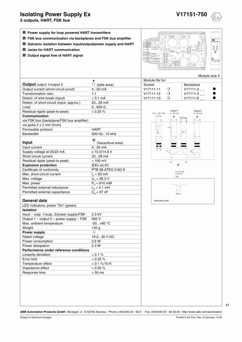
61
ABB Automation Products GmbH · Borsigstr. 2 · D-63755 Alzenau · Phone +49(0)60 23 - 92 0 · Fax +49(0)60 23 - 92 33 00 · http://www.abb.com/automation
Subject to technical changes. Printed in the Fed. Rep. of Germany 12.00
Isolating Power Supply Ex V17151-7502 outputs, HART, FSK bus
Power supply for loop powered HART transmitters
FSK bus communication via backplanes and FSK bus amplifier
Galvanic isolation between input/output/power supply and HART
Jacks for HART communication
Output signal free of HART signal
Module size 4Module fits for:
Output output 1/output 2 (safe area) Socket BackplaneOutput current (short-circuit proof) 4...20 mA V17111-11 V17111-2 _ _
Transformation ratio 1:1 V17111-12 V17111-3 _ _
Detect. of wire break (input) < 0.1 mA V17111-13 V17111-6 _ _
Detect. of short-circuit (input, approx.) 23...28 mALoad 0...600 ΩResidual ripple (peak-to-peak) < 0.25 %Communicationvia FSK bus (backplane/FSK bus amplifier)via jacks 2 x 2 mm (front)Permeable protocol HARTBandwidth 500 Hz...10 kHz
Input (hazardous area)Input current 4...20 mASupply voltage at 20/22 mA ≥ 15.5/14.8 VShort circuit current 23...28 mAResidual ripple (peak-to-peak) < 100 mVExplosion protection [EEx ia] IICCertificate of conformity PTB 98 ATEX 2183 XMax. short-circuit current Io = 93 mAMax. voltage Uo = 26.3 VMax. power Po = 610 mWPermitted external inductance La = 4.1 mHPermitted external capacitance Ca = 97 nF
General dataLED indicators, power “On“ (green)IsolationInput – outp. 1/outp. 2/power supply/FSK 2.3 kVOutput 1 – output 2 – power supply – FSK 500 VMax. ambient temperature -20...+60 °CWeight 140 gPower supplyRated voltage 19.2...30 V DCPower consumption 2.6 WPower dissipation 2.3 WPerformance under reference conditionsLinearity deviation < 0.1 %Error limit < 0.25 %Temperature effect < 0.1 %/10 KImpedance effect < 0.05 %Response time < 50 ms
15
21
14
+ -
+ -
211 2
EEx ia
gn
-
-
54
+ -
mA
-
63
+ -
-
-
87
FSK 1
19.2...30 V DC
2.6 W
4...20 mA(15.5 V)
FSK
4...20 mA
Output 1 Output 24...20 mA
FSK (Bus)
Hazardous area

62
ABB Automation Products GmbH · Borsigstr. 2 · D-63755 Alzenau · Phone +49(0)60 23 - 92 0 · Fax +49(0)60 23 - 92 33 00 · http://www.abb.com/automation
Subject to technical changes. Printed in the Fed. Rep. of Germany 12.00
Isolating Power Supply Ex V17151-7552 outputs, HART
Power supply for loop powered HART transmitters
Galvanic isolation between input/output/power supply and HART
Testjacks for mA signal
Jacks for HART communication
Module size 4Module fits for:
Output output 1/output 2 (safe area) Socket BackplaneOutput current (short-circuit proof) 4...20 mA V17111-11 V17111-2 _ _
Transformation ratio 1:1 V17111-12 V17111-3 _ _
Detect. of wire break (input) < 0.1 mA V17111-13 V17111-6 _ _
Detect. of short-circuit (input, approx.) 23...28 mALoad 0...600 ΩResidual ripple (peak-to-peak) < 0.25 %Communicationvia mA signalvia jacks 2 x 2 mm (front)Permeable protocol HARTBandwidth 500 Hz...10 kHz
Input (hazardous area)Input current 4...20 mASupply voltage at 20/22 mA ≥ 15.5/14.8 VShort circuit current 23...28 mAResidual ripple (peak-to-peak) < 100 mVExplosion protection [EEx ia] IICCertificate of conformity PTB 98 ATEX 2183 XMax. short-circuit current Io = 93 mAMax. voltage Uo = 26.3 VMax. power Po = 610 mWPermitted external inductance La = 4.1 mHPermitted external capacitance Ca = 97 nF
General dataLED indicators, power “On“ (green)IsolationInput – outp. 1/outp. 2/power supply/FSK 2.3 kVOutput 1 – output 2 – power supply – FSK 500 VMax. ambient temperature -20...+60 °CWeight 140 gPower supplyRated voltage 19.2...30 V DCPower consumption 2.6 WPower dissipation 2.3 WPerformance under reference conditionsLinearity deviation < 0.1 %Error limit < 0.25 %Temperature effect < 0.1 %/10 KImpedance effect < 0.05 %Response time < 50 ms
15
21
14
+ -
+ -
211 2
EEx ia
-
-
54
+ -
FSK
mA
-
63
+ -
-
-
19.2...30 V DC
2.6 W
4...20 mA(15.5 V)
FSK
4...20 mAFSK*
4...20 mA
Hazardous area
gn
FSK*
* FSK only at load ≥ 250 Ω
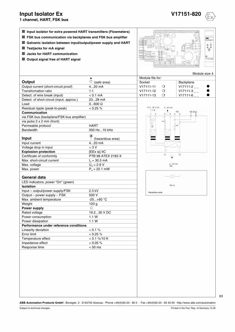
63
ABB Automation Products GmbH · Borsigstr. 2 · D-63755 Alzenau · Phone +49(0)60 23 - 92 0 · Fax +49(0)60 23 - 92 33 00 · http://www.abb.com/automation
Subject to technical changes. Printed in the Fed. Rep. of Germany 12.00
Input Isolator Ex V17151-8201 channel, HART, FSK bus
Input isolator for extra powered HART transmitters (Flowmeters)
FSK bus communication via backplanes and FSK bus amplifier
Galvanic isolation between input/output/power supply and HART
Testjacks for mA signal
Jacks for HART communication
Output signal free of HART signal
Module size 4Module fits for:
Output (safe area) Socket BackplaneOutput current (short-circuit proof) 4...20 mA V17111-11 V17111-2 _ _
Transformation ratio 1:1 V17111-12 V17111-3 _ _
Detect. of wire break (input) < 0.1 mA V17111-13 V17111-6 _ _
Detect. of short circuit (input, approx.) 23...28 mALoad 0...600 ΩResidual ripple (peak-to-peak) < 0.25 %Communicationvia FSK bus (backplane/FSK bus amplifier)via jacks 2 x 2 mm (front)Permeable protocol HARTBandwidth 500 Hz...10 kHz
Input (hazardous area)Input current 4...20 mAVoltage drop in input < 3 VExplosion protection [EEx ia] IICCertificate of conformity PTB 98 ATEX 2183 XMax. short-circuit current Io = 30.5 mAMax. voltage Uo = 2.9 VMax. power Po = 22.1 mW
General dataLED indicators, power “On“ (green)IsolationInput – output/power supply/FSK 2.3 kVOutput – power supply – FSK 500 VMax. ambient temperature -20...+60 °CWeight 120 gPower supplyRated voltage 19.2...30 V DCPower consumption 1.1 WPower dissipation 1.1 WPerformance under reference conditionsLinearity deviation < 0.1 %Error limit < 0.25 %Temperature effect < 0.1 %/10 KImpedance effect < 0.05 %Response time < 50 ms
7
15
8635421
+
14
-
+ -
+ -
EEx ia
FSKgn
-
mA
-
-
4...20 mA19.2...30 V DC
1.1 W
4...20 mAFSK
FSK (Bus)
Hazardous area
FSK
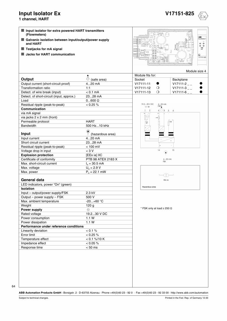
64
ABB Automation Products GmbH · Borsigstr. 2 · D-63755 Alzenau · Phone +49(0)60 23 - 92 0 · Fax +49(0)60 23 - 92 33 00 · http://www.abb.com/automation
Subject to technical changes. Printed in the Fed. Rep. of Germany 12.00
Input Isolator Ex V17151-8251 channel, HART
Input isolator for extra powered HART transmitters (Flowmeters)
Galvanic isolation between input/output/power supply and HART
Testjacks for mA signal
Jacks for HART communication
Module size 4Module fits for:
Output (safe area) Socket BackplaneOutput current (short-circuit proof) 4...20 mA V17111-11 V17111-2 _ _
Transformation ratio 1:1 V17111-12 V17111-3 _ _
Detect. of wire break (input) < 0.1 mA V17111-13 V17111-6 _ _
Detect. of short-circuit (input, approx.) 23...28 mALoad 0...600 ΩResidual ripple (peak-to-peak) < 0.25 %Communicationvia mA signalvia jacks 2 x 2 mm (front)Permeable protocol HARTBandwidth 500 Hz...10 kHz
Input (hazardous area)Input current 4...20 mAShort circuit current 23...28 mAResidual ripple (peak-to-peak) < 100 mVVoltage drop in input < 3 VExplosion protection [EEx ia] IICCertificate of conformity PTB 98 ATEX 2183 XMax. short-circuit current Io = 30.5 mAMax. voltage Uo = 2.9 VMax. power Po = 22.1 mW
General dataLED indicators, power “On“ (green)IsolationInput – output/power supply/FSK 2.3 kVOutput – power supply – FSK 500 VMax. ambient temperature -20...+60 °CWeight 120 gPower supplyRated voltage 19.2...30 V DCPower consumption 1.1 WPower dissipation 1.1 WPerformance under reference conditionsLinearity deviation < 0.1 %Error limit < 0.25 %Temperature effect < 0.1 %/10 KImpedance effect < 0.05 %Response time < 50 ms
15
635421
+
14
-
+ -
+ -
EEx ia
FSKgn
-
mA
-
-
19.2...30 V DC
1.1 W
4...20 mA
FSK
4...20 mAFSK*
Hazardous area
* FSK only at load ≥ 250 Ω
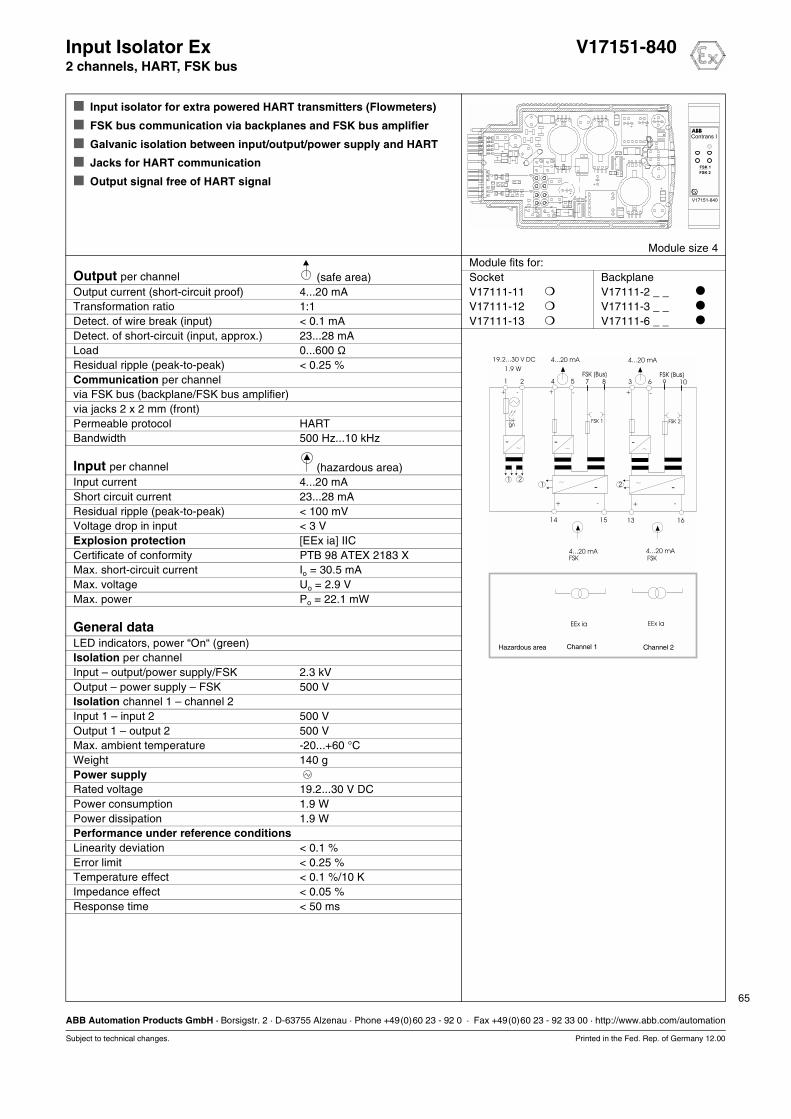
65
ABB Automation Products GmbH · Borsigstr. 2 · D-63755 Alzenau · Phone +49(0)60 23 - 92 0 · Fax +49(0)60 23 - 92 33 00 · http://www.abb.com/automation
Subject to technical changes. Printed in the Fed. Rep. of Germany 12.00
Input Isolator Ex V17151-8402 channels, HART, FSK bus
Input isolator for extra powered HART transmitters (Flowmeters)
FSK bus communication via backplanes and FSK bus amplifier
Galvanic isolation between input/output/power supply and HART
Jacks for HART communication
Output signal free of HART signal
Module size 4Module fits for:
Output per channel (safe area) Socket BackplaneOutput current (short-circuit proof) 4...20 mA V17111-11 V17111-2 _ _
Transformation ratio 1:1 V17111-12 V17111-3 _ _
Detect. of wire break (input) < 0.1 mA V17111-13 V17111-6 _ _
Detect. of short-circuit (input, approx.) 23...28 mALoad 0...600 ΩResidual ripple (peak-to-peak) < 0.25 %Communication per channelvia FSK bus (backplane/FSK bus amplifier)via jacks 2 x 2 mm (front)Permeable protocol HARTBandwidth 500 Hz...10 kHz
Input per channel (hazardous area)Input current 4...20 mAShort circuit current 23...28 mAResidual ripple (peak-to-peak) < 100 mVVoltage drop in input < 3 VExplosion protection [EEx ia] IICCertificate of conformity PTB 98 ATEX 2183 XMax. short-circuit current Io = 30.5 mAMax. voltage Uo = 2.9 VMax. power Po = 22.1 mW
General dataLED indicators, power “On“ (green)Isolation per channelInput – output/power supply/FSK 2.3 kVOutput – power supply – FSK 500 VIsolation channel 1 – channel 2Input 1 – input 2 500 VOutput 1 – output 2 500 VMax. ambient temperature -20...+60 °CWeight 140 gPower supplyRated voltage 19.2...30 V DCPower consumption 1.9 WPower dissipation 1.9 WPerformance under reference conditionsLinearity deviation < 0.1 %Error limit < 0.25 %Temperature effect < 0.1 %/10 KImpedance effect < 0.05 %Response time < 50 ms
15 16
8 107 95 64 321
+ +
14 13
- -
+ +- -
+ -
211 2
EEx ia EEx ia
FSK 1 FSK 2gn
- - -
- -
19.2...30 V DC
1.9 W
4...20 mA 4...20 mAFSK FSK
4...20 mA 4...20 mA
FSK (Bus) FSK (Bus)
Hazardous area Channel 1 Channel 2
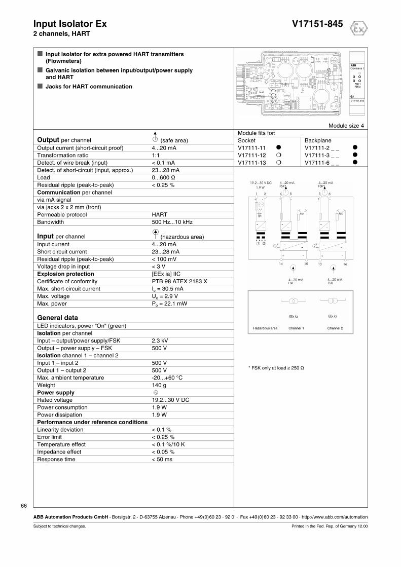
66
ABB Automation Products GmbH · Borsigstr. 2 · D-63755 Alzenau · Phone +49(0)60 23 - 92 0 · Fax +49(0)60 23 - 92 33 00 · http://www.abb.com/automation
Subject to technical changes. Printed in the Fed. Rep. of Germany 12.00
Input Isolator Ex V17151-8452 channels, HART
Input isolator for extra powered HART transmitters(Flowmeters)
Galvanic isolation between input/output/power supply and HART
Jacks for HART communication
Module size 4Module fits for:
Output per channel (safe area) Socket BackplaneOutput current (short-circuit proof) 4...20 mA V17111-11 V17111-2 _ _
Transformation ratio 1:1 V17111-12 V17111-3 _ _
Detect. of wire break (input) < 0.1 mA V17111-13 V17111-6 _ _
Detect. of short-circuit (input, approx.) 23...28 mALoad 0...600 ΩResidual ripple (peak-to-peak) < 0.25 %Communication per channelvia mA signalvia jacks 2 x 2 mm (front)Permeable protocol HARTBandwidth 500 Hz...10 kHz
Input per channel (hazardous area)Input current 4...20 mAShort circuit current 23...28 mAResidual ripple (peak-to-peak) < 100 mVVoltage drop in input < 3 VExplosion protection [EEx ia] IICCertificate of conformity PTB 98 ATEX 2183 XMax. short-circuit current Io = 30.5 mAMax. voltage Uo = 2.9 VMax. power Po = 22.1 mW
General dataLED indicators, power “On“ (green)Isolation per channelInput – output/power supply/FSK 2.3 kVOutput – power supply – FSK 500 VIsolation channel 1 – channel 2Input 1 – input 2 500 VOutput 1 – output 2 500 VMax. ambient temperature -20...+60 °CWeight 140 gPower supplyRated voltage 19.2...30 V DCPower consumption 1.9 WPower dissipation 1.9 WPerformance under reference conditionsLinearity deviation < 0.1 %Error limit < 0.25 %Temperature effect < 0.1 %/10 KImpedance effect < 0.05 %Response time < 50 ms
15 16
21
14 13
+ +- -
+ -
211 2
EEx ia EEx ia
gn
-
- -
54
+ -
FSK
-
63
+ -
FSK
-
19.2...30 V DC
1.9 W
4...20 mA 4...20 mA
4...20 mAFSK*
4...20 mAFSK*
FSK FSK
Hazardous area Channel 1 Channel 2
* FSK only at load ≥ 250 Ω

Analog Modules
12.00 67
Transmitter
Intelligent Transmitter 1 channel, LCI V17152-31_
Temperature Transmitter Ex 1 channel, Pt 100 V17152-61_
Intelligent Transmitter Ex 1 channel, LCI V17152-62_
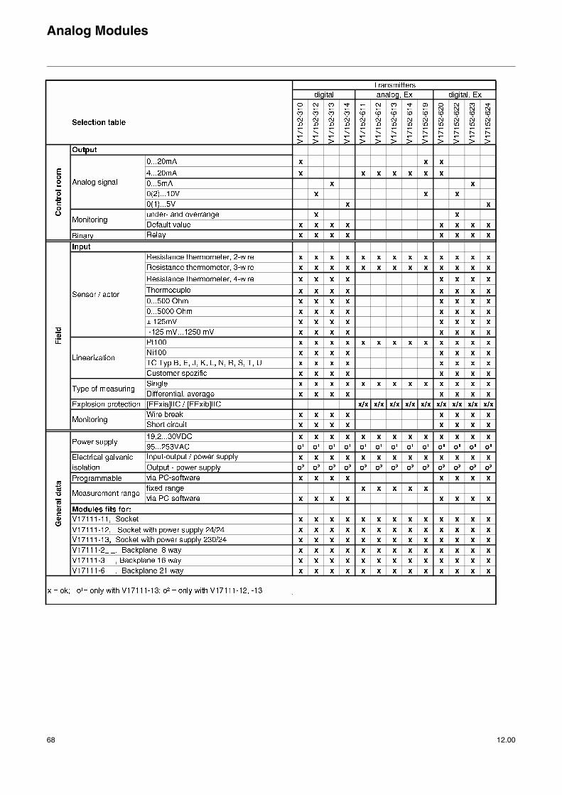
Analog Modules
68 12.00
!"#
!"$#
!"#
%! &
'!
'!
(
)
*
%+%&","-"."/"*""0"%"1
+ &2
0
"
,3&& 4,,3566+74,,38566+
98:
0!
;"$+
;$+
6& & 7&# &&
' & &# &&
)8 )+#
3
)+#
<$"0 :#!&# &&$7
<==" :&>#
<$==" :&?#
<?==" :&#
3@:AB@#!<$AC@#!<"$
<"0 :
<"0 :#!&# &&7
%
",3 ",3
%&
07
D
D
D
)# &&
,
/2
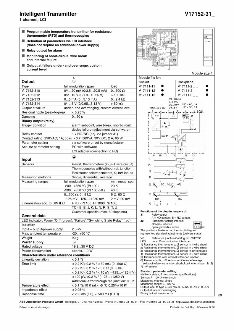
69
ABB Automation Products GmbH · Borsigstr. 2 · D-63755 Alzenau · Phone +49(0)60 23 - 92 0 · Fax +49(0)60 23 - 92 33 00 · http://www.abb.com/automation
Subject to technical changes. Printed in the Fed. Rep. of Germany 12.00
Intelligent Transmitter V17152-31_1 channel, LCI
Programmable temperature transmitter for resistancethermometer (RTD) and thermocouples
Definition of parameters via LCI interface(does not require an additional power supply)
Relay output for alarm
Monitoring of short-circuit, wire break and internal failure
Output at failure under- and overrange, custom current level
Module size 4Module fits for:
Output Socket BackplaneType full modulation span load V17111-11 V17111-2 _ _
V17152-310 0/4...20 mA (0/3.8...20.5 mA) 0...600 Ω V17111-12 V17111-3 _ _
V17152-312 0/2...10 V (0/1.9...10.25 V) > 100 kΩ V17111-13 V17111-6 _ _
V17152-313 0...5 mA (0...5.13 mA) 0...2,4 kΩV17152-314 0/1...5 V (0/0.95...5.13 V) > 50 kΩOutput at failure under- and overranging, custom current levelResidual ripple (peak-to-peak) < 0.25 % Damping 0...30 sBinary output (relay)Trigger condition alarm set-point, wire break, short-circuit,
device failure (adjustment via software)Relay contact 1 x NO/NC (adj. via jumper J1)Contact rating: 250VAC; 1A; cosϕ > 0.7; 560VA; 30V DC; 2 A; 60 WParameter setting via software or set by manufacturerAcc. for parameter setting PC with software
LCI adapter (connection to PC)
Input Sensors Resist. thermometers (2-,3-,4 wire circuit)
Thermocouples with/without ref. junctionResistance teletransmitters, Ω, mV inputs
Measuring methods Single, differential, averageMeasuring ranges full modulation span min. meas. span
-200...+850 °C (Pt 100) 20 K-200...+850 °C (Pt 100 diff.) 40 K0...500 Ω; 0...5 kΩ 5 Ω; 50 Ω±125 mV; -125...+1250 mV 2 mV; 20 mV
Linearization acc. to DIN IEC RTD - Pt 100, Pt 1000, Ni 100; TC - B, E, J, K, L, N, R, S, T, UCustomer specific (max. 60 tiepoints)
General dataLED indicator: Power “On“ (green); “Failure“/“Switching State Relay“ (red)IsolationInput – output/power supply 2.3 kVMax. ambient temperature -20...+60 °CWeight 90 gPower supplyRated voltage 19.2...30 V DCPower consumption approx. 1.0 WCharacteristics under reference conditionsLinearity deviation < 0.1 %Error limit < 0.2 K/< 0.2 % / < 80 mΩ (0...500 Ω)
< 0.2 K/< 0.2 % / < 0.8 Ω (0...5 kΩ)< 0.2 K/< 0.2 % / < 10 µV (-125...+125 mV)< 100 µV/<0.2 % / (-125...+1250 V)Additional error through ref. junction: 0.5 K
Temperature effect < 0.1 %/10 K (at < -5 °C 0.25%/10 K)Impedance effect < 0.05 % Response time < 250 ms (TC), < 500 ms (RTD)
Functions of the plug-in jumpers J.:J1 Relay output
A = NO contact; B = NC contactJ2 Parameter setting interlock
closed = inactiveopen (parked) = active
The positions illustrated on the circuit diagramrepresented standard adjustments (delivery status)
VG Reference junction Catalog No. 0317093LKS Local Communication Interface1) Resistance thermometers, Ω sensor in 4-wire circuit2) Resistance thermometers, Ω sensor in 3-wire circuit3) Resistance thermometers, Ω sensor in diff./average4) Resistance thermometers, Ω sensor in 2-wire circuit5) Thermocouple with internal reference junction6) Thermocouple, mV sensor in difference/average
(without reference junction short-circuit to terminals 11/12)7) mV sensor
Standard parameter setting:(delivery status, if no customer specifications)Sensor: Pt 100, 3-wire circuitMeasuring method: singleMeasuring range: 0...100 °COutput: acc. to type 4...20 mA, 0...5 mA, 0...10 V, 0...5 VOutput at failure: overrangingBinary output: sensor error
4
14
5-
15
1
+
2
1316
3 6
+ -LKS
A/D
J2µC
gn
J1BA
rt
µC
1211
+
+
+
+
-
-
-
-
VGTC
TC2
1)
3)
5)
2)
4)
6)
7)
TC1
ϑ
ϑ
ϑ ϑ
ϑ
ϑ
21
0/4...20 mA0...5 mA0/2...10 V0/1...5 V
250 V AC, 1 A30 V DC, 2 A19.2...30 V DC
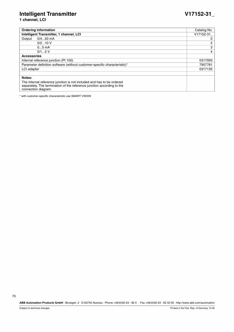
70
ABB Automation Products GmbH · Borsigstr. 2 · D-63755 Alzenau · Phone +49(0)60 23 - 92 0 · Fax +49(0)60 23 - 92 33 00 · http://www.abb.com/automation
Subject to technical changes. Printed in the Fed. Rep. of Germany 12.00
* with customer-specific characteristic use SMART VISION
Intelligent Transmitter V17152-31_1 channel, LCI
Ordering information Catalog No.Intelligent Transmitter, 1 channel, LCI V17152-31_Output 0/4...20 mA 0
0/2...10 V 20...5 mA 30/1...5 V 4
AccessoriesInternal reference junction (Pt 100) 0317093Parameter definition software (without customer-specific characteristic)* 7957781LCI adapter 0317135
Notes:The internal reference junction is not included and has to be orderedseparately. The termination of the reference junction according to theconnection diagram.

71
ABB Automation Products GmbH · Borsigstr. 2 · D-63755 Alzenau · Phone +49(0)60 23 - 92 0 · Fax +49(0)60 23 - 92 33 00 · http://www.abb.com/automation
Subject to technical changes. Printed in the Fed. Rep. of Germany 12.00
Temperature Transmitter Ex V17152-61_Pt 100, 1 channel
Connection of resistance thermometer Pt 100
Input [EEx ia] IIC
Line break monitoring, rise or drop
Module size 2Module fits for:
Output Socket BackplaneConnection Terminals 4(+); 5(-) V17111-11 V17111-2 _ _
Output current 4...20 mA, temperature linear V17111-12 V17111-3 _ _
(optional 0...20 mA, 0...10 V)1) V17111-13 V17111-6 _ _
Wire break at input > 22 mA/< 3,6 mA (rise/drop)Load 0...600 ΩResidual ripple < 0,25 %
(peak-to-peak – parasitic voltage at input)
Output Connection Terminals 12, 13, 14, 15
for resistance thermometer Pt 100Input circuit 2-, 3-wire circuitLine resistance 0 Ω for 2-wire circuit
(10 Ω for ext. line balancing optional)Measurement start -100 °CMax. measuring range -100...+850 °CMin. measuring span 60 °CExplosion protection [EEx ia] IICCertificate of conformity PTB No. Ex-97.D.2030 XMax. short-circuit current Io = 19 mAMax. voltage Uo = 20 VMax. capacity Po = 95 mWPermitted external inductance La = 75 mHPermitted external capacitance Ca = 140 nF
General dataDisplay green LED – power “On“Test voltage 2.3 kV input – output/power supplyMax. ambient temperature -20...+60 °CWeight 90 gPower supplyConnection Terminals 1(+); 2(-)Rated voltage 19.2...30 V DCPower consumption approx. 1.0 WCharacteristics under reference conditionsLinearity deviation < 0.1 %Measurement deviation < 0.5 %Temperature effect < 0.1 %/10 K for -5...+60 °C
< 0.2 %/10 K for -20...-5 °CLoad effect < 0.05 % in load range 0...600 ΩResponse time < 350 ms
Functions of the plug-in jumpers J.:
J1/J2 Wire break monitoringA = output signal, riseB = output signal, drop
The positions illustrated on the circuit diagramrepresented standard adjustments (delivery status)
5
gn
13 12 111514
1 2 4
++ --
A BJ1
J2
Hazardous area
Inputs [EEx ia] IIC
19.2...30 VDC 4...20mA

72
ABB Automation Products GmbH · Borsigstr. 2 · D-63755 Alzenau · Phone +49(0)60 23 - 92 0 · Fax +49(0)60 23 - 92 33 00 · http://www.abb.com/automation
Subject to technical changes. Printed in the Fed. Rep. of Germany 12.00
2) Example: 100...200 °C/2-wire/0...20 mA
Temperature Transmitter Ex V17152-61_Pt 100, 1 channel
Ordering information Catalog No.Temperature Transmitter Ex, Pt 100, 1 channel V17152-61_Meas. range 0... 60 °C, 3-wire, 4...20 mA 1
0...100 °C, 3-wire, 4...20 mA 20...150 °C, 3-wire, 4...20 mA 30...200 °C, 3-wire, 4...20 mA 4.......2) 9

73
ABB Automation Products GmbH · Borsigstr. 2 · D-63755 Alzenau · Phone +49(0)60 23 - 92 0 · Fax +49(0)60 23 - 92 33 00 · http://www.abb.com/automation
Subject to technical changes. Printed in the Fed. Rep. of Germany 12.00
Intelligent Transmitter Ex V17152-62_1 channel, LCI
Programmable temperature transmitter for resistancethermometer (RTD) and thermocouples
Definition of parameters via LCI interface(does not require an additional power supply)
Relay output for alarm
Monitoring of short-circuit, wire break and internal failure
Module size 4Output Module fits for:Type full modulation span load Socket BackplaneV17152-620 0/4...20 mA (0/3.8...20.5 mA) 0...600 Ω V17111-11 V17111-2 _ _
V17152-622 0/2...10 V (0/1.9...10.25 V) > 100 kΩ V17111-12 V17111-3 _ _
V17152-623 0...5 mA (0...5.13 mA) 0...2,4 kΩ V17111-13 V17111-6 _ _
V17152-624 0/1...5 V (0/0.95...5.13 V) > 50 kΩOutput at failure under- and overranging, custom current levelResidual ripple (peak-to-peak) < 0.25 % Damping 0...30 sBinary output (relay)Trigger condition: alarm set-point, wire break, short-circuit, device failureRelay contact 1 x NO/NC (adj. via jumper J1)Contact rating: 250VAC; 1A; cosϕ > 0.7; 560VA; 30V DC; 2 A; 60 WInput Sensors Resist. thermometers (2-,3-,4 wire circuit)
Thermocouples with/without ref. junctionResistance teletransmitters, Ω, mV inputs
Measuring methods Single, differential, averageMeasuring ranges full modulation span min. meas. span
-200...+850 °C (Pt 100) 20 K-200...+850 °C (Pt 100 diff.) 40 K0...500 Ω; 0...5 kΩ 5 Ω; 50 Ω±125 mV; -125...+1250 mV 2 mV; 20 mV
Linearization acc. to DIN IEC RTD - Pt 100, Pt 1000, Ni 100; TC - B, E, J, K, L, N, R, S, T, UCustomer specific (max. 60 tiepoints)
Explosion protection [EEx ia] IICCertificate of conformity PTB 99 ATEX 2013 XMax. short-circuit current Io = 2 mAMax. voltage Uo = 5,4 VMax. power Po = 2 mWPermitted external inductance La = 5 mHPermitted external capacitance Ca = 1650 nFGeneral dataLED indicator: power “On“ (green)/“Failure“/“Switching State Relay“ (red)IsolationInput – output/power supply/FSK 2.3 kVMax. ambient temperature -20...+60 °CWeight 90 gPower supplyRated voltage 19.2...30 V DCPower consumption approx. 1.0 WCharacteristics under reference conditionsLinearity deviation < 0.1 %Error limit < 0.2 K/< 0.2 % / < 80 mΩ (0...500 Ω)(additional error through < 0.2 K/< 0.2 % / < 0.8 Ω (0...5 kΩ)reference junction: 0.5 K) < 0.2 K/< 0.2 % / < 10 µV (-125...+125 mV)
< 100 µV/<0.2 % / (-125...+1250 V)Temperature effect < 0.1 %/10 K (at < -5 °C 0.25%/10 K)Impedance effect < 0.05 % Response time < 250 ms (TC), < 500 ms (RTD)
Functions of the plug-in jumpers J.:J1 Relay output
A = NO contact; B = NC contactJ2 Parameter setting interlock
closed = inactiveopen (parked) = active
The positions illustrated on the circuit diagramrepresented standard adjustments (delivery status)
VG Reference junction Catalog No. 0317093LKS Local Communication Interface1) Resistance thermometers, Ω sensor in 4-wire circuit2) Resistance thermometers, Ω sensor in 3-wire circuit3) Resistance thermometers, Ω sensor in diff./average4) Resistance thermometers, Ω sensor in 2-wire circuit5) Thermocouple with internal reference junction*6) Thermocouple, mV sensor in difference/average
(without reference junction short-circuit to terminals 11/12)7) mV sensor
Standard parameter setting:(delivery status, if no customer specifications)Sensor: Pt 100, 3-wire circuitMeasuring method: singleMeasuring range: 0...100 °COutput: acc. to type 4...20 mA, 0...5 mA, 0...10 V, 0...5 VOutput at failure: overrangingBinary output: sensor error
4
14
5
-
15
1
+
2
1316
3 6
+ -
LKS
+
+
+
+
-
-
-
-
VGTC
TC2
A/D
J2µC
J1BA
µC
1211
1)
3)
5)
2)
4)
6)
7)
TC1
ϑ
ϑ
ϑ ϑ
ϑ
ϑ
21
0/4...20 mA0...5 mA0/2...10 V0/1...5 V
250 V AC, 1 A30 V DC, 2 A19.2...30 V DC
Hazardous area
gnrd
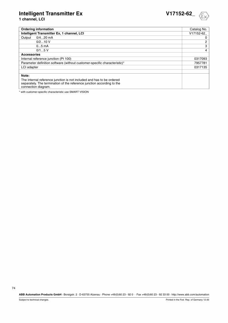
74
ABB Automation Products GmbH · Borsigstr. 2 · D-63755 Alzenau · Phone +49(0)60 23 - 92 0 · Fax +49(0)60 23 - 92 33 00 · http://www.abb.com/automation
Subject to technical changes. Printed in the Fed. Rep. of Germany 12.00
* with customer-specific characteristic use SMART VISION
Intelligent Transmitter Ex V17152-62_1 channel, LCI
Ordering information Catalog No.Intelligent Transmitter Ex, 1 channel, LCI V17152-62_Output 0/4...20 mA 0
0/2...10 V 20...5 mA 30/1...5 V 4
AccessoriesInternal reference junction (Pt 100) 0317093Parameter definition software (without customer-specific characteristic)* 7957781LCI adapter 0317135
Note:The internal reference junction is not included and has to be orderedseparately. The termination of the reference junction according to theconnection diagram.

Analog Modules
12.00 75
Output Isolators
Loop Powered Isolator 1 channel V17153-11
Loop Powered Isolator 1 channel, bypass V17153-115
Loop Powered Isolator 2 channels V17153-13
Isolating Driver 1 channel V17153-21
Isolating Driver 1 channel, HART V17153-22
Isolating Driver 1 channel, HART, FSK bus V17153-420
Loop Powered Isolator Ex 1 channel V17153-51
Loop Powered Isolator Ex 1 channel, bypass V17153-515
Loop Powered Isolator Ex 1 channel, HART V17153-52
Isolating Driver Ex 1 channel V17153-61
Isolating Driver Ex 1 channel, HART V17153-62
Isolating Driver Ex 1 channel, HART, FSK bus V17153-820
Isolating Driver Ex 1 channel, HART V17153-825
Isolating Driver Ex 2 channels, HART, FSK bus V17153-840
Isolating Driver Ex 2 channels, HART V17153-845
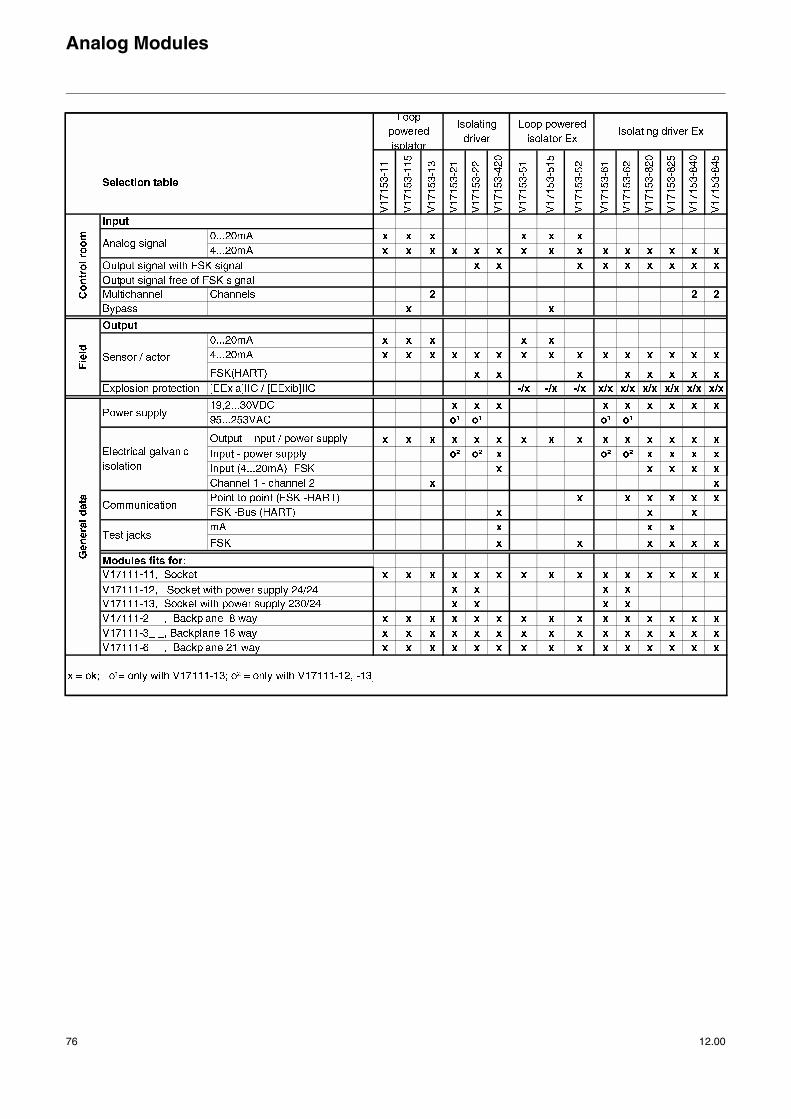
Analog Modules
76 12.00
!"#$
%& '%%& ())*'%%& +())
,-./01
-22/0
3 *
)3
) $3
,3
4 3!"#$
3 !"#$
0,5,,,3,/.6 /*
0,5,,,377.68
0,5,,,3/77.6,9
0,5,,,3977.6,
&:6;<: 0,5,,,3,/;=: 0,5,,,3,.3,/
#>6
4
% ?
0,5,,,3,,.6
0,5,,,3,.6 *
)
@ ?
A@
%&) @ ?%&
*
A
@

77
ABB Automation Products GmbH · Borsigstr. 2 · D-63755 Alzenau · Phone +49(0)60 23 - 92 0 · Fax +49(0)60 23 - 92 33 00 · http://www.abb.com/automation
Subject to technical changes. Printed in the Fed. Rep. of Germany 12.00
Loop Powered Isolator V17153-111 channel
Electrical isolation for standard signals 0(4)...20 mA(I/P converter, positioner)
Low voltage drop
Module size 1Module fits for:
Input Socket BackplaneInput current (0)4...20 mA V17111-11 V17111-2 _ _
Overranging > 23.6 mA, max. 40 mA V17111-12 V17111-3 _ _
V17111-13 V17111-6 _ _
OutputOutput current (short-circuit proof) (0)4...20 mATransformation ratio 1:1Detect. of overranging (input, approx.) > 23.6 mA, max. 40 mALoad 0...750 Ω
General dataVoltage drop < 1.5 VIsolationInput – output 1.35 kV1)
Max. ambient temperature -20...+60 °CWeight 40 gPerformance under reference conditionsLinearity deviation < 0.1 %Error limit < 0.1 %Temperature effect < 0.1 %/10 KImpedance effect < 0.18 %Response time < 50 ms
1) Rating voltage 50 V acc. to DIN EN 61010
0(4)...20 mA
0(4)...20 mA
IP
+ -
-+
4 5
1514
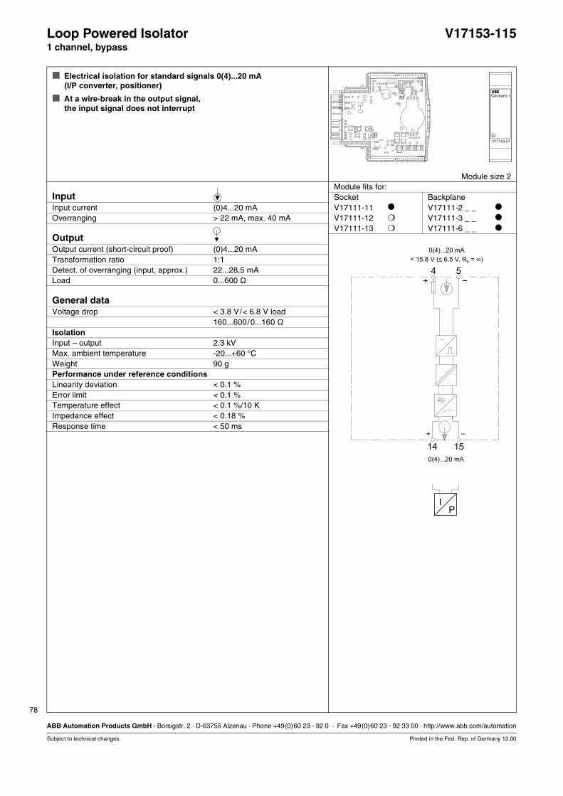
78
ABB Automation Products GmbH · Borsigstr. 2 · D-63755 Alzenau · Phone +49(0)60 23 - 92 0 · Fax +49(0)60 23 - 92 33 00 · http://www.abb.com/automation
Subject to technical changes. Printed in the Fed. Rep. of Germany 12.00
Loop Powered Isolator V17153-1151 channel, bypass
Electrical isolation for standard signals 0(4)...20 mA(I/P converter, positioner)
At a wire-break in the output signal,the input signal does not interrupt
Module size 2Module fits for:
Input Socket BackplaneInput current (0)4...20 mA V17111-11 V17111-2 _ _
Overranging > 22 mA, max. 40 mA V17111-12 V17111-3 _ _
V17111-13 V17111-6 _ _
OutputOutput current (short-circuit proof) (0)4...20 mATransformation ratio 1:1Detect. of overranging (input, approx.) 22...28,5 mALoad 0...600 Ω
General dataVoltage drop < 3.8 V/< 6.8 V load
160...600/0...160 ΩIsolationInput – output 2.3 kVMax. ambient temperature -20...+60 °CWeight 90 gPerformance under reference conditionsLinearity deviation < 0.1 %Error limit < 0.1 %Temperature effect < 0.1 %/10 KImpedance effect < 0.18 %Response time < 50 ms
IP
+ -
-+
4 5
1514
0(4)...20 mA
< 15.8 V ( 6.5 V, R = )≤ ∞B
0(4)...20 mA

79
ABB Automation Products GmbH · Borsigstr. 2 · D-63755 Alzenau · Phone +49(0)60 23 - 92 0 · Fax +49(0)60 23 - 92 33 00 · http://www.abb.com/automation
Subject to technical changes. Printed in the Fed. Rep. of Germany 12.00
Loop Powered Isolator V17153-132 channels
Electrical isolation for standard signals 0(4)...20 mA(I/P converter, positioner)
Low voltage drop
Module size 2Module fits for:
Input per channel Socket BackplaneInput current (0)4...20 mA V17111-11 V17111-2 _ _
Overranging > 23.6 mA, max. 40 mA V17111-12 V17111-3 _ _
V17111-13 V17111-6 _ _
Output per channelOutput current (short-circuit proof) (0)4...20 mATransformation ratio 1:1Detect. of overranging (input, approx.) > 23.6 mA, max. 40 mALoad 0...750 Ω
General dataVoltage drop < 1.5 VIsolationInput – output 1.35 kV1)
Channel 1 – channel 2 500 VMax. ambient temperature -20...+60 °CWeight 90 gPerformance under reference conditionsLinearity deviation < 0.1 %Error limit < 0.1 %Temperature effect < 0.1 %/10 KImpedance effect < 0.18 %Response time < 50 ms
1) Rating voltage 50 V acc. to DIN EN 61010
0(4)...20 mA 0(4)...20 mA
0(4)...20 mA 0(4)...20 mA
I IP P
+ +- -
- -+ +
4 35 6
15 1614 13
Channel 1 Channel 2

80
ABB Automation Products GmbH · Borsigstr. 2 · D-63755 Alzenau · Phone +49(0)60 23 - 92 0 · Fax +49(0)60 23 - 92 33 00 · http://www.abb.com/automation
Subject to technical changes. Printed in the Fed. Rep. of Germany 12.00
Isolating Driver V17153-211 channel
Isolating driver for I/P converter
Minimal power consumption
Module size 2Module fits for:
Input Socket BackplaneInput current 4...20 mA V17111-11 V17111-2 _ _
Voltage drop < 1.5 V V17111-12 V17111-3 _ _
V17111-13 V17111-6 _ _
OutputOutput current (short-circuit proof) 4...20 mATransformation ratio 1:1Detect. of wire-break (input) < 0.1 mADetect. of overranging (input, approx.) 22...30 mALoad 0...600 ΩResidual ripple (peak-to-peak) < 0.25 %
General dataLED indicators, power “On“ (green)IsolationOutput – input/power supply 2.3 kVMax. ambient temperature -20...+60 °CWeight 90 gPower supplyRated voltage 19.2...30 V DCPower consumption 0.7 WPower dissipation 0.7 WPerformance under reference conditionsLinearity deviation < 0.1 %Error limit < 0.25 %Temperature effect < 0.1 %/10 KImpedance effect < 0.1 %Response time < 50 ms
gn
+
+
- + -
-
4...20 mA
4...20 mA
1 2 4 5 3 6
1514
IP
19.2...30 V DC
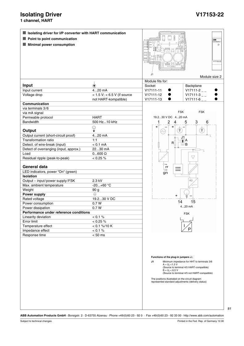
81
ABB Automation Products GmbH · Borsigstr. 2 · D-63755 Alzenau · Phone +49(0)60 23 - 92 0 · Fax +49(0)60 23 - 92 33 00 · http://www.abb.com/automation
Subject to technical changes. Printed in the Fed. Rep. of Germany 12.00
Isolating Driver V17153-221 channel, HART
Isolating driver for I/P converter with HART communication
Point to point communication
Minimal power consumption
Module size 2Module fits for:
Input Socket BackplaneInput current 4...20 mA V17111-11 V17111-2 _ _
Voltage drop < 1.5 V; < 6.5 V (if source V17111-12 V17111-3 _ _
not HART-kompatible) V17111-13 V17111-6 _ _
Communicationvia terminals 3/6via mA signalPermeable protocol HARTBandwidth 500 Hz...10 kHz
OutputOutput current (short-circuit proof) 4...20 mATransformation ratio 1:1Detect. of wire-break (input) < 0.1 mADetect of overranging (input, approx.) 22...30 mALoad 0...600 ΩResidual ripple (peak-to-peak) < 0.25 %
General dataLED indicators, power “On“ (green)IsolationOutput – input/power supply/FSK 2.3 kVMax. ambient temperature -20...+60 °CWeight 90 gPower supplyRated voltage 19.2...30 V DCPower consumption 0.7 WPower dissipation 0.7 WPerformance under reference conditionsLinearity deviation < 0.1 %Error limit < 0.25 %Temperature effect < 0.1 %/10 KImpedance effect < 0.1 %Response time < 50 ms
B
A
gn
+ -
-
+
+
-
1 2 4 5 3 6
J1
1514
IP
R
4...20 mA
FSK FSK
4...20 mA
FSK
19.2...30 V DC
Functions of the plug-in jumpers J.:
J1 Minimum impedance for HHT to terminals 3/6A = Ui <1.5 V(Source to terminal 4/5 HART-compatible)B = Ui < 6.5 V(Source to terminal 4/5 not HART-compatible)
The positions illustrated on the circuit diagramrepresented standard adjustments (delivery status)

82
ABB Automation Products GmbH · Borsigstr. 2 · D-63755 Alzenau · Phone +49(0)60 23 - 92 0 · Fax +49(0)60 23 - 92 33 00 · http://www.abb.com/automation
Subject to technical changes. Printed in the Fed. Rep. of Germany 12.00
Isolating Driver V17153-4201 channel, HART, FSK bus
Isolating driver for I/P converter, positioner with HART-communication
FSK bus communication via backplanes and FSK bus amplifier
Galvanic isolation between input/output/power supply and HART
Testjacks for mA signal
Jacks for HART communication
Module size 4Module fits for:
Input Socket BackplaneInput current 4...20 mA V17111-11 V17111-2 _ _
Voltage drop < 6.9 V V17111-12 V17111-3 _ _
Communication V17111-13 V17111-6 _ _
via FSK bus (backplane/FSK bus amplifier)via jacks 2 x 2 mm (front)Permeable protocol HARTBandwidth 500 Hz...10 kHz
OutputOutput current (short-circuit proof) 4...20 mATransformation ratio 1:1Detect. of wire break (input) < 0.1 mADetect. of overranging (input, approx.) 23...29 mALoad 0...700 ΩResidual ripple (peak-to-peak) < 0.25 %
General dataLED indicators, power “On“ (green)IsolationOutput – input/power supply/FSK 2.3 kVInput – power supply – FSK 500 VMax. ambient temperature -20...+60 °CWeight 120 gPower supplyRated voltage 19.2...30 V DCPower consumption 1.1 WPower dissipation 1.1 WPerformance under reference conditionsLinearity deviation < 0.1 %Error limit < 0.25 %Temperature effect < 0.1 %/10 KImpedance effect < 0.05 %Response time < 50 ms
7
15
8635421
+
14
-
+ -
+ -
FSKgn
-
mA
-
-
19.2...30 V DC1.1 W
4...20 mA0...700 ΩFSK
4...20 mA
FSK
FSK*
FSK (Bus)
* FSK only at load ≥ 250 Ω=for the current source
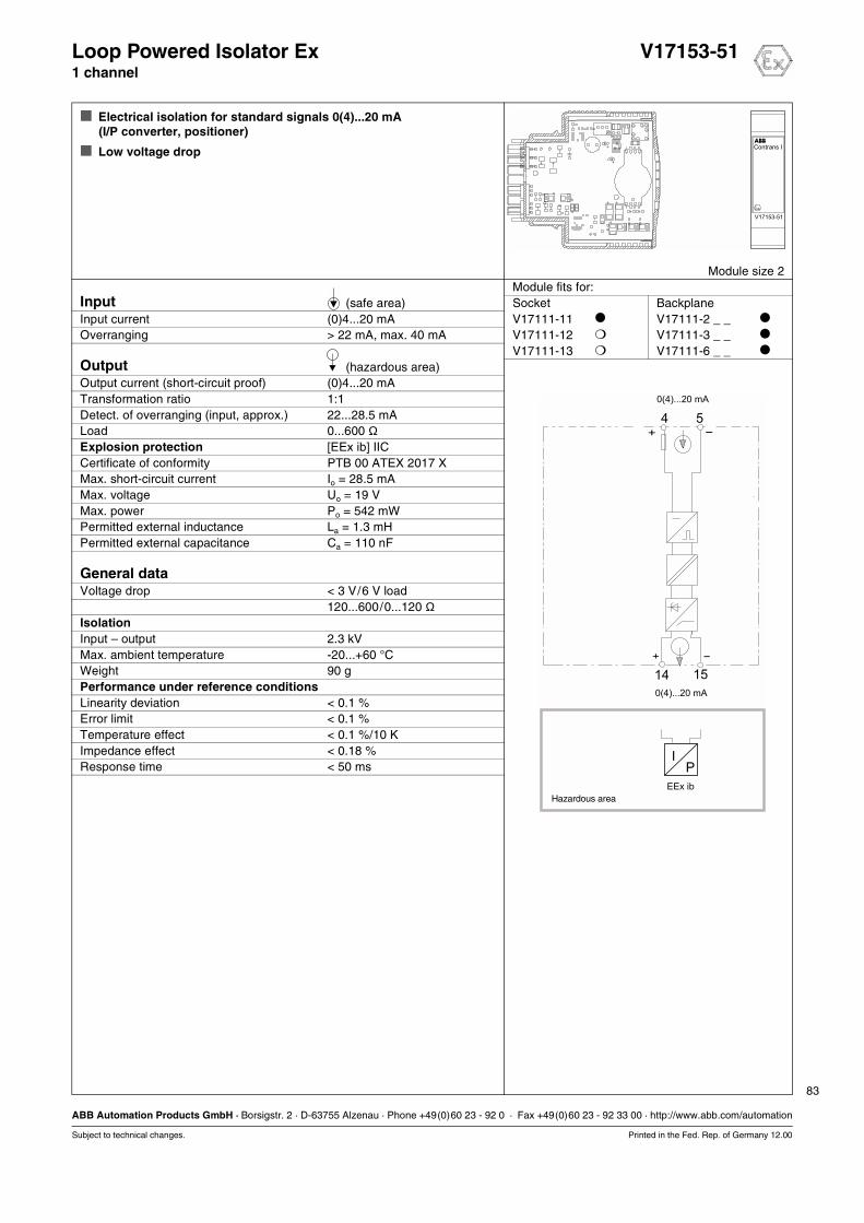
83
ABB Automation Products GmbH · Borsigstr. 2 · D-63755 Alzenau · Phone +49(0)60 23 - 92 0 · Fax +49(0)60 23 - 92 33 00 · http://www.abb.com/automation
Subject to technical changes. Printed in the Fed. Rep. of Germany 12.00
Loop Powered Isolator Ex V17153-511 channel
Electrical isolation for standard signals 0(4)...20 mA(I/P converter, positioner)
Low voltage drop
Module size 2Module fits for:
Input (safe area) Socket BackplaneInput current (0)4...20 mA V17111-11 V17111-2 _ _
Overranging > 22 mA, max. 40 mA V17111-12 V17111-3 _ _
V17111-13 V17111-6 _ _
Output (hazardous area)Output current (short-circuit proof) (0)4...20 mATransformation ratio 1:1Detect. of overranging (input, approx.) 22...28.5 mALoad 0...600 ΩExplosion protection [EEx ib] IICCertificate of conformity PTB 00 ATEX 2017 XMax. short-circuit current Io = 28.5 mAMax. voltage Uo = 19 VMax. power Po = 542 mWPermitted external inductance La = 1.3 mHPermitted external capacitance Ca = 110 nF
General dataVoltage drop < 3 V/6 V load
120...600/0...120 ΩIsolationInput – output 2.3 kVMax. ambient temperature -20...+60 °CWeight 90 gPerformance under reference conditionsLinearity deviation < 0.1 %Error limit < 0.1 %Temperature effect < 0.1 %/10 KImpedance effect < 0.18 %Response time < 50 ms
IP
+ -
-+
4 5
1514
0(4)...20 mA
0(4)...20 mA
EEx ib
Hazardous area
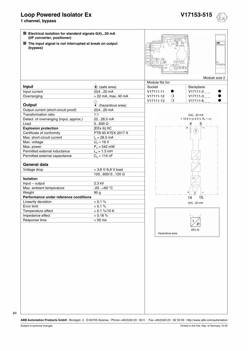
84
ABB Automation Products GmbH · Borsigstr. 2 · D-63755 Alzenau · Phone +49(0)60 23 - 92 0 · Fax +49(0)60 23 - 92 33 00 · http://www.abb.com/automation
Subject to technical changes. Printed in the Fed. Rep. of Germany 12.00
Loop Powered Isolator Ex V17153-5151 channel, bypass
Electrical isolation for standard signals 0(4)...20 mA(I/P converter, positioner)
The input signal is not interrupted at break on output(bypass)
Module size 2Module fits for:
Input (safe area) Socket BackplaneInput current (0)4...20 mA V17111-11 V17111-2 _ _
Overranging > 22 mA, max. 40 mA V17111-12 V17111-3 _ _
V17111-13 V17111-6 _ _
Output (hazardous area)Output current (short-circuit proof) (0)4...20 mATransformation ratio 1:1Detect. of overranging (input, approx.) 22...28.5 mALoad 0...600 ΩExplosion protection [EEx ib] IICCertificate of conformity PTB 00 ATEX 2017 XMax. short-circuit current Io = 28.5 mAMax. voltage Uo = 19 VMax. power Po = 542 mWPermitted external inductance La = 1.3 mHPermitted external capacitance Ca = 110 nF
General dataVoltage drop < 3,8 V/6,8 V load
120...600/0...120 ΩIsolationInput – output 2.3 kVMax. ambient temperature -20...+60 °CWeight 90 gPerformance under reference conditionsLinearity deviation < 0.1 %Error limit < 0.1 %Temperature effect < 0.1 %/10 KImpedance effect < 0.18 %Response time < 50 ms I
P
+ -
-+
4 5
1514
0(4)...20 mA
EEx ib
0(4)...20 mA
Hazardous area
< 15.8 V ( 6.5 V, R = )≤ ∞B
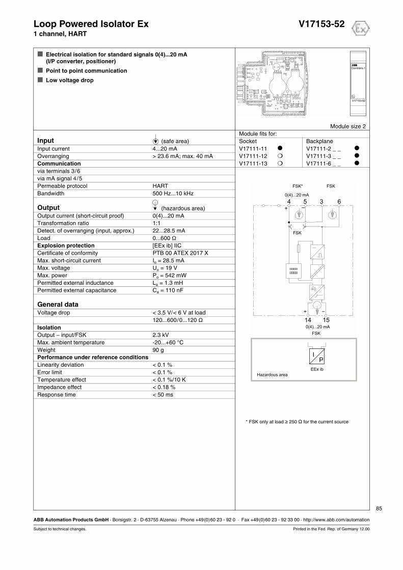
85
ABB Automation Products GmbH · Borsigstr. 2 · D-63755 Alzenau · Phone +49(0)60 23 - 92 0 · Fax +49(0)60 23 - 92 33 00 · http://www.abb.com/automation
Subject to technical changes. Printed in the Fed. Rep. of Germany 12.00
Loop Powered Isolator Ex V17153-521 channel, HART
Electrical isolation for standard signals 0(4)...20 mA(I/P converter, positioner)
Point to point communication
Low voltage drop
Module size 2Module fits for:
Input (safe area) Socket BackplaneInput current 4...20 mA V17111-11 V17111-2 _ _
Overranging > 23.6 mA; max. 40 mA V17111-12 V17111-3 _ _
Communication V17111-13 V17111-6 _ _
via terminals 3/6via mA signal 4/5Permeable protocol HARTBandwidth 500 Hz...10 kHz
Output (hazardous area)Output current (short-circuit proof) 0(4)...20 mATransformation ratio 1:1Detect. of overranging (input, approx.) 22...28.5 mALoad 0...600 ΩExplosion protection [EEx ib] IICCertificate of conformity PTB 00 ATEX 2017 XMax. short-circuit current Io = 28.5 mAMax. voltage Uo = 19 VMax. power Po = 542 mWPermitted external inductance La = 1.3 mHPermitted external capacitance Ca = 110 nF
General dataVoltage drop < 3.5 V/< 6 V at load
120...600/0...120 ΩIsolationOutput – input/FSK 2.3 kVMax. ambient temperature -20...+60 °CWeight 90 gPerformance under reference conditionsLinearity deviation < 0.1 %Error limit < 0.1 %Temperature effect < 0.1 %/10 KImpedance effect < 0.18 %Response time < 50 ms
+ -
-+
0(4)...20 mA
0(4)...20 mA
4 5 3 6
1514
IP
FSK* FSK
FSK
FSK
EEx ib
Hazardous area
* FSK only at load ≥ 250 Ω=for the current source
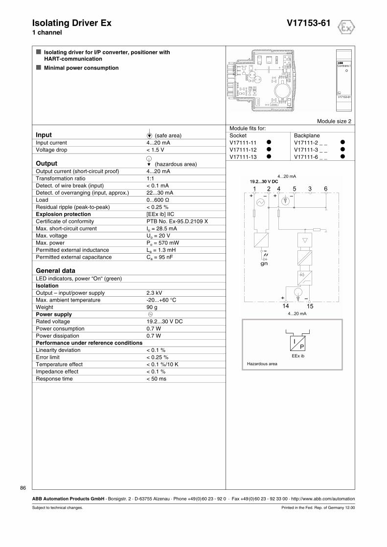
86
ABB Automation Products GmbH · Borsigstr. 2 · D-63755 Alzenau · Phone +49(0)60 23 - 92 0 · Fax +49(0)60 23 - 92 33 00 · http://www.abb.com/automation
Subject to technical changes. Printed in the Fed. Rep. of Germany 12.00
Isolating Driver Ex V17153-611 channel
Isolating driver for I/P converter, positioner with HART-communication
Minimal power consumption
Module size 2Module fits for:
Input (safe area) Socket BackplaneInput current 4...20 mA V17111-11 V17111-2 _ _
Voltage drop < 1.5 V V17111-12 V17111-3 _ _
V17111-13 V17111-6 _ _
Output (hazardous area)Output current (short-circuit proof) 4...20 mATransformation ratio 1:1Detect. of wire break (input) < 0.1 mADetect. of overranging (input, approx.) 22...30 mALoad 0...600 ΩResidual ripple (peak-to-peak) < 0.25 %Explosion protection [EEx ib] IICCertificate of conformity PTB No. Ex-95.D.2109 XMax. short-circuit current Io = 28.5 mAMax. voltage Uo = 20 VMax. power Po = 570 mWPermitted external inductance La = 1.3 mHPermitted external capacitance Ca = 95 nF
General dataLED indicators, power “On“ (green)IsolationOutput – input/power supply 2.3 kVMax. ambient temperature -20...+60 °CWeight 90 gPower supplyRated voltage 19.2...30 V DCPower consumption 0.7 WPower dissipation 0.7 WPerformance under reference conditionsLinearity deviation < 0.1 %Error limit < 0.25 %Temperature effect < 0.1 %/10 KImpedance effect < 0.1 %Response time < 50 ms
gn
+
+
- + -
-
4...20 mA
4...20 mA
1 2 4 5 3 6
1514
IP
EEx ib
19.2...30 V DC
Hazardous area
19.2...30 V DC

87
ABB Automation Products GmbH · Borsigstr. 2 · D-63755 Alzenau · Phone +49(0)60 23 - 92 0 · Fax +49(0)60 23 - 92 33 00 · http://www.abb.com/automation
Subject to technical changes. Printed in the Fed. Rep. of Germany 12.00
Isolating Driver Ex V17153-621 channel, HART
Isolating driver for I/P converter, positioner with HART-communication
Point to point communication
Minimal power consumption
Module size 2Module fits for:
Input (safe area) Socket BackplaneInput current 4...20 mA V17111-11 V17111-2 _ _
Voltage drop < 1.5 V; < 6.5 V (if source V17111-12 V17111-3 _ _
not HART compatible) V17111-13 V17111-6 _ _
Communicationvia terminals 3/6via mA signal 4/5Permeable protocol HARTBandwidth 500 Hz...10 kHz
Output (hazardous area)Output current (short-circuit proof) 4...20 mATransformation ratio 1:1Detect. of wire break (input) < 0.1 mADetect. of overranging (input, approx.) 22...30 mALoad 0...600 ΩResidual ripple (peak-to-peak) < 0.25 %Explosion protection [EEx ib] IICCertificate of conformity PTB No. Ex-95.D.2190 XMax. short-circuit current Io = 28.5 mAMax. voltage Uo = 20 VMax. power Po = 570 mWPermitted external inductance La = 1.3 mHPermitted external capacitance Ca = 95 nF
General dataLED indicators, power “On“ (green)IsolationOutput – input/power supply/FSK 2.3 kVMax. ambient temperature -20...+60 °CWeight 90 gPower supplyRated voltage 19.2...30 V DCPower consumption 0.7 WPower dissipation 0.7 WPerformance under reference conditionsLinearity deviation < 0.1 %Error limit < 0.25 %Temperature effect < 0.1 %/10 KImpedance effect < 0.1 %Response time < 50 ms
B
A
gn
+ -
-
+
+
-
4...20 mA
FSK FSK
FSK
4...20 mA
1 2 4 5 3 6
J1
1514
IP
R
19,2...30 V DC
EEx ib
Hazardous area
Functions of the plug-in jumpers J.:
J1 Minimum impedance for HHT to terminals 3/6A = Ui <1.5 V(Source to terminal 4/5 HART-compatible)B = Ui < 6.5 V(Source to terminal 4/5 not HART-compatible)
The positions illustrated on the circuit diagramrepresented standard adjustments (delivery status)

88
ABB Automation Products GmbH · Borsigstr. 2 · D-63755 Alzenau · Phone +49(0)60 23 - 92 0 · Fax +49(0)60 23 - 92 33 00 · http://www.abb.com/automation
Subject to technical changes. Printed in the Fed. Rep. of Germany 12.00
Isolating Driver Ex V17153-8201 channel, HART, FSK bus
Isolating driver for I/P converter, positioner with HART-communication
FSK bus communication via backplanes and FSK bus amplifier
Galvanic isolation between input/output/power supply and HART
Testjacks for mA signal
Jacks for HART communication
Module size 4Module fits for:
Input (safe area) Socket BackplaneInput current 4...20 mA V17111-11 V17111-2 _ _
Voltage drop < 6.9 V V17111-12 V17111-3 _ _
Communication V17111-13 V17111-6 _ _
via FSK bus (backplane/FSK bus amplifier)via jacks 2 x 2 mm (front)Permeable protocol HARTBandwidth 500 Hz...10 kHz
Output (hazardous area)Output current (short-circuit proof) 4...20 mATransformation ratio 1:1Detect. of wire break (input) < 0.1 mADetect. of overranging (input, approx.) 23...29 mALoad 0...700 ΩResidual ripple (peak-to-peak) < 0.25 %Explosion protection [EEx ia] IICCertificate of conformity PTB 98 ATEX 2183 XMax. short-circuit current Io = 93 mAMax. voltage Uo = 26.3 VMax. power Po = 610 mWPermitted external inductance La = 4.1 mHPermitted external capacitance Ca = 97 nF
General dataLED indicators, power “On“ (green)IsolationInput – output/power supply/FSK 2.3 kVOutput – power supply – FSK 500 VMax. ambient temperature -20...+60 °CWeight 120 gPower supplyRated voltage 19.2...30 V DCPower consumption 1.1 WPower dissipation 1.1 WPerformance under reference conditionsLinearity deviation < 0.1 %Error limit < 0.25 %Temperature effect < 0.1 %/10 KImpedance effect < 0.05 %Response time < 50 ms
7
15
8635421
+
14
-
+ -
+ -
EEx ia
FSKgn
-
mA
-
-
4...20 mA0...700 ΩFSK
FSK (Bus)
Hazardous area
19.2...30 V DC
1.1 W
4...20 mA
FSK*
FSK
* FSK only at load ≥ 250 Ω=for the current source
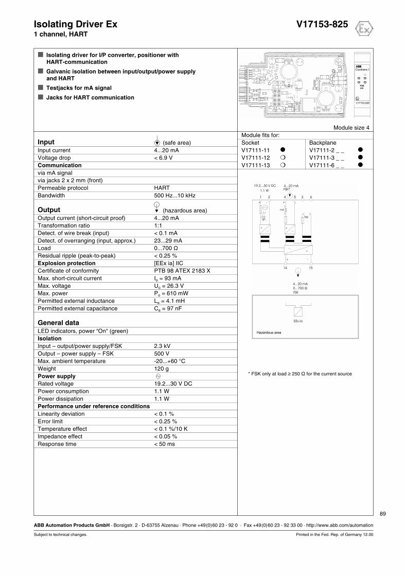
89
ABB Automation Products GmbH · Borsigstr. 2 · D-63755 Alzenau · Phone +49(0)60 23 - 92 0 · Fax +49(0)60 23 - 92 33 00 · http://www.abb.com/automation
Subject to technical changes. Printed in the Fed. Rep. of Germany 12.00
Isolating Driver Ex V17153-8251 channel, HART
Isolating driver for I/P converter, positioner with HART-communication
Galvanic isolation between input/output/power supply and HART
Testjacks for mA signal
Jacks for HART communication
Module size 4Module fits for:
Input (safe area) Socket BackplaneInput current 4...20 mA V17111-11 V17111-2 _ _
Voltage drop < 6.9 V V17111-12 V17111-3 _ _
Communication V17111-13 V17111-6 _ _
via mA signalvia jacks 2 x 2 mm (front)Permeable protocol HARTBandwidth 500 Hz...10 kHz
Output (hazardous area)Output current (short-circuit proof) 4...20 mATransformation ratio 1:1Detect. of wire break (input) < 0.1 mADetect. of overranging (input, approx.) 23...29 mALoad 0...700 ΩResidual ripple (peak-to-peak) < 0.25 %Explosion protection [EEx ia] IICCertificate of conformity PTB 98 ATEX 2183 XMax. short-circuit current Io = 93 mAMax. voltage Uo = 26.3 VMax. power Po = 610 mWPermitted external inductance La = 4.1 mHPermitted external capacitance Ca = 97 nF
General dataLED indicators, power “On“ (green)IsolationInput – output/power supply/FSK 2.3 kVOutput – power supply – FSK 500 VMax. ambient temperature -20...+60 °CWeight 120 gPower supplyRated voltage 19.2...30 V DCPower consumption 1.1 WPower dissipation 1.1 WPerformance under reference conditionsLinearity deviation < 0.1 %Error limit < 0.25 %Temperature effect < 0.1 %/10 KImpedance effect < 0.05 %Response time < 50 ms
15
635421
+
14
-
+ -
+ -
EEx ia
FSKgn
-
mA
-
-
19.2...30 V DC
1.1 W
4...20 mA
FSK
4...20 mAFSK*
0...700 Ω
Hazardous area
* FSK only at load ≥ 250 Ω=for the current source

90
ABB Automation Products GmbH · Borsigstr. 2 · D-63755 Alzenau · Phone +49(0)60 23 - 92 0 · Fax +49(0)60 23 - 92 33 00 · http://www.abb.com/automation
Subject to technical changes. Printed in the Fed. Rep. of Germany 12.00
Isolating Driver Ex V17153-8402 channels, HART, FSK bus
Isolating driver for I/P converter, positioner with HART-communication
FSK bus communication via backplanes and FSK bus amplifier
Galvanic isolation between input/output/power supply and HART
Jacks for HART communication
Module size 4Module fits for:
Input per channel (safe area) Socket BackplaneInput current 4...20 mA V17111-11 V17111-2 _ _
Voltage drop < 6.9 V V17111-12 V17111-3 _ _
Communication per channel V17111-13 V17111-6 _ _
via FSK bus (backplane/FSK bus amplifier)via jacks 2 x 2 mm (front)Permeable protocols HARTBandwidth 500 Hz...10 kHz
Output per channel (hazardous area)Output current (short-circuit proof) 4...20 mATransformation ratio 1:1Detect. of wire break (input) < 0.1 mADetect. of short-circuit (input, approx.) 23...28 mALoad 0...600 ΩResidual ripple (peak-to-peak) < 0.25 %Overranging in input 23...28 mAExplosion protection [EEx ia] IICCertificate of conformity PTB 98 ATEX 2183 XMax. short-circuit current Io = 93 mAMax. voltage Uo = 26.3 VMax. power Po = 610 mWPermitted external inductance La = 4.1 mHPermitted external capacitance Ca = 97 nF
General dataLED indicators, power “On“ (green)Isolation per channelInput – output/power supply/FSK 2.3 kVOutput – power supply/FSK 500 VIsolation channel 1 – channel 2Input 1 – input 2 500 VOutput 1 – output 2 500 VMax. ambient temperature -20...+60 °CWeight 140 gPower supplyRated voltage 19.2...30 V DCPower consumption 2,2 WPower dissipation 2,2 WPerformance under reference conditionsLinearity deviation < 0.1 %Error limit < 0.25 %Temperature effect < 0.1 %/10 KImpedance effect < 0.05 %Response time < 50 ms
15 16
8 107 95 64 321
+ +
14 13
- -
+ +- -
+ -
211 2
EEx ia EEx ia
FSK 1 FSK 2gn
- - -
- -
19.2...30 V DC
2.2 W
4...20 mA 4...20 mA
FSK FSK
4...20 mA 4...20 mA
FSK (Bus)
FSK*FSK*
FSK (Bus)
0...700 Ω 0...700 Ω
Hazardous area Channel 1 Channel 2
* FSK only at load ≥ 250 Ω=for the current source
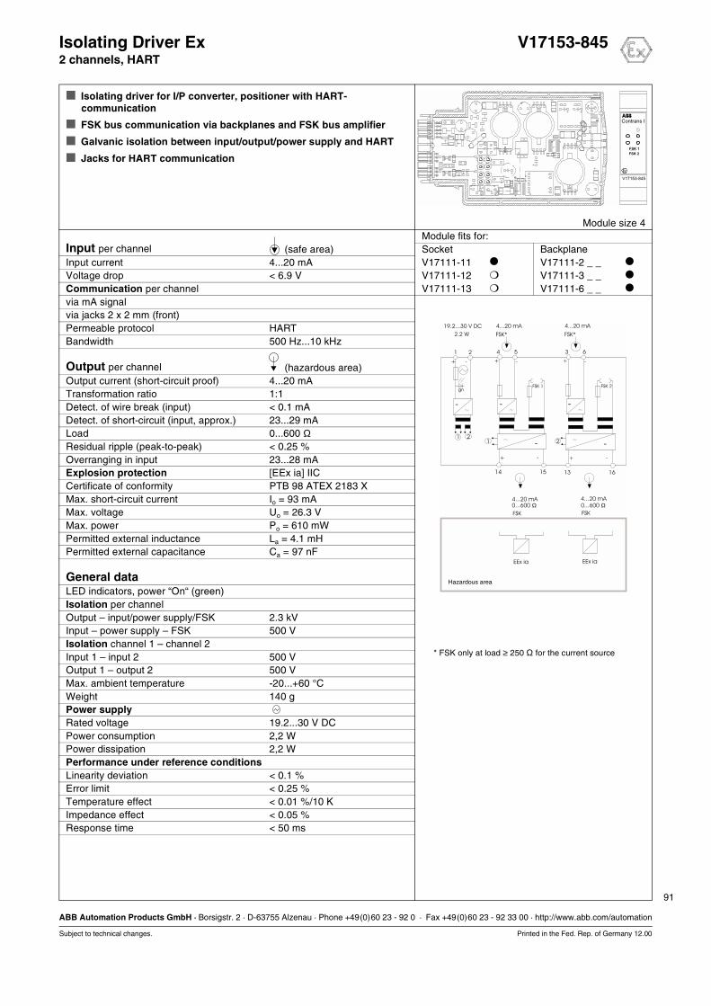
91
ABB Automation Products GmbH · Borsigstr. 2 · D-63755 Alzenau · Phone +49(0)60 23 - 92 0 · Fax +49(0)60 23 - 92 33 00 · http://www.abb.com/automation
Subject to technical changes. Printed in the Fed. Rep. of Germany 12.00
Isolating Driver Ex V17153-8452 channels, HART
Isolating driver for I/P converter, positioner with HART-communication
FSK bus communication via backplanes and FSK bus amplifier
Galvanic isolation between input/output/power supply and HART
Jacks for HART communication
Module size 4Module fits for:
Input per channel (safe area) Socket BackplaneInput current 4...20 mA V17111-11 V17111-2 _ _
Voltage drop < 6.9 V V17111-12 V17111-3 _ _
Communication per channel V17111-13 V17111-6 _ _
via mA signalvia jacks 2 x 2 mm (front)Permeable protocol HARTBandwidth 500 Hz...10 kHz
Output per channel (hazardous area)Output current (short-circuit proof) 4...20 mATransformation ratio 1:1Detect. of wire break (input) < 0.1 mADetect. of short-circuit (input, approx.) 23...29 mALoad 0...600 ΩResidual ripple (peak-to-peak) < 0.25 %Overranging in input 23...28 mAExplosion protection [EEx ia] IICCertificate of conformity PTB 98 ATEX 2183 XMax. short-circuit current Io = 93 mAMax. voltage Uo = 26.3 VMax. power Po = 610 mWPermitted external inductance La = 4.1 mHPermitted external capacitance Ca = 97 nF
General dataLED indicators, power “On“ (green)Isolation per channelOutput – input/power supply/FSK 2.3 kVInput – power supply – FSK 500 VIsolation channel 1 – channel 2Input 1 – input 2 500 VOutput 1 – output 2 500 VMax. ambient temperature -20...+60 °CWeight 140 gPower supplyRated voltage 19.2...30 V DCPower consumption 2,2 WPower dissipation 2,2 WPerformance under reference conditionsLinearity deviation < 0.1 %Error limit < 0.25 %Temperature effect < 0.01 %/10 KImpedance effect < 0.05 %Response time < 50 ms
15 16
21
14 13
+ +- -
+ -
211 2
EEx ia EEx ia
-
- -
54
+ -
FSK 1
-
63
+ -
FSK 2
-
4...20 mA 4...20 mA
FSK FSK
0...600 Ω 0...600 Ω
Hazardous area
19.2...30 V DC
2.2 W
4...20 mA
FSK*
4...20 mA
FSK*
gn
* FSK only at load ≥ 250 Ω=for the current source

Monitoring Modules
12.00 93
Trip Amplifier
Trip Amplifier 2 alarms, 2 relays V17171-11
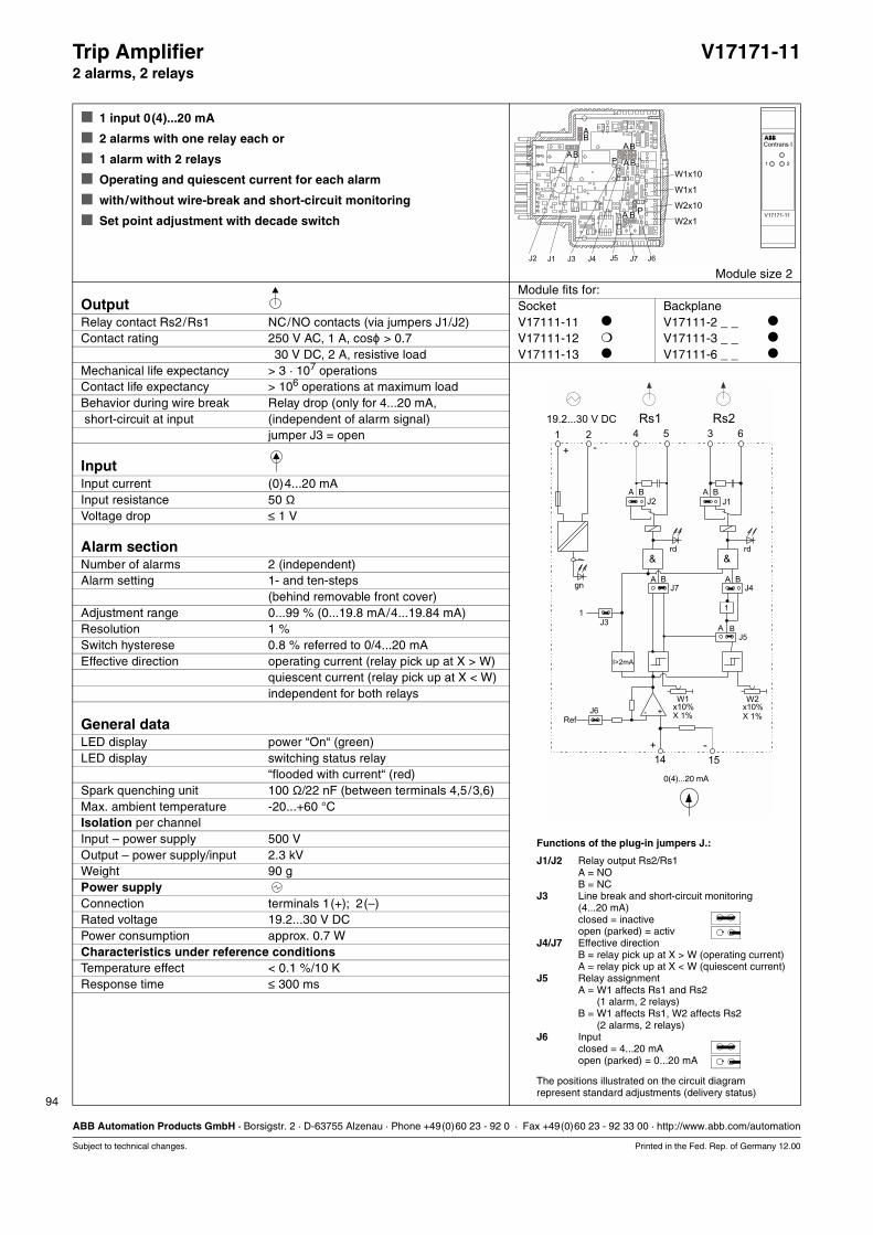
94
ABB Automation Products GmbH · Borsigstr. 2 · D-63755 Alzenau · Phone +49(0)60 23 - 92 0 · Fax +49(0)60 23 - 92 33 00 · http://www.abb.com/automation
Subject to technical changes. Printed in the Fed. Rep. of Germany 12.00
Trip Amplifier V17171-112 alarms, 2 relays
1 input 0(4)...20 mA
2 alarms with one relay each or
1 alarm with 2 relays
Operating and quiescent current for each alarm
with/without wire-break and short-circuit monitoring
Set point adjustment with decade switch
Module size 2Module fits for:
Output Socket BackplaneRelay contact Rs2/Rs1 NC/NO contacts (via jumpers J1/J2) V17111-11 V17111-2 _ _
Contact rating 250 V AC, 1 A, cosϕ > 0.7 V17111-12 V17111-3 _ _
30 V DC, 2 A, resistive load V17111-13 V17111-6 _ _
Mechanical life expectancy > 3 · 107 operationsContact life expectancy > 106 operations at maximum loadBehavior during wire break Relay drop (only for 4...20 mA, short-circuit at input (independent of alarm signal)
jumper J3 = open
InputInput current (0)4...20 mAInput resistance 50 ΩVoltage drop ≤ 1 V
Alarm sectionNumber of alarms 2 (independent)Alarm setting 1- and ten-steps
(behind removable front cover)Adjustment range 0...99 % (0...19.8 mA/4...19.84 mA)Resolution 1 %Switch hysterese 0.8 % referred to 0/4...20 mAEffective direction operating current (relay pick up at X > W)
quiescent current (relay pick up at X < W)independent for both relays
General dataLED display power “On“ (green)LED display switching status relay
“flooded with current“ (red)Spark quenching unit 100 Ω/22 nF (between terminals 4,5/3,6)Max. ambient temperature -20...+60 °CIsolation per channelInput – power supply 500 VOutput – power supply/input 2.3 kVWeight 90 gPower supplyConnection terminals 1(+); 2(–)Rated voltage 19.2...30 V DCPower consumption approx. 0.7 WCharacteristics under reference conditionsTemperature effect < 0.1 %/10 KResponse time ≤ 300 ms
Functions of the plug-in jumpers J.:
J1/J2 Relay output Rs2/Rs1A = NOB = NC
J3 Line break and short-circuit monitoring(4...20 mA)closed = inactiveopen (parked) = activ
J4/J7 Effective directionB = relay pick up at X > W (operating current)A = relay pick up at X < W (quiescent current)
J5 Relay assignmentA = W1 affects Rs1 and Rs2A = (1 alarm, 2 relays)B = W1 affects Rs1, W2 affects Rs2B = (2 alarms, 2 relays)
J6 Inputclosed = 4...20 mAopen (parked) = 0...20 mA
The positions illustrated on the circuit diagramrepresent standard adjustments (delivery status)
1 2 3 6
A B
A B
J4
J1
+ -
0(4)...20 mA
+ -
14 15
&
Ref
J6 - +
4 5
A B
A B
J7
J2
&
J3
1
I>2mA
W1
x10%
X 1%
W2x10%
X 1%
1
A B
J5
19.2...30 V DC
rd
gn
rd
Rs1 Rs2
Sockets, Backplanes
12.00 95
Sockets, Backplanes
Socket V17111-11
Socket with power supply 24/24 V17111-12
Socket with power supply 230/24 V17111-13
Backplane, 8-way V17111-2_ _
Backplane, 16-way V17111-3_ _
Backplane, 21-way V17111-6_ _
Dimensional drawings
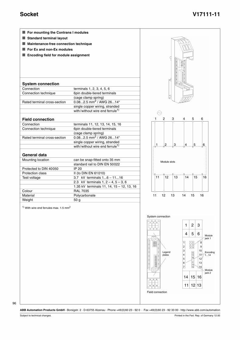
96
ABB Automation Products GmbH · Borsigstr. 2 · D-63755 Alzenau · Phone +49(0)60 23 - 92 0 · Fax +49(0)60 23 - 92 33 00 · http://www.abb.com/automation
Subject to technical changes. Printed in the Fed. Rep. of Germany 12.00
Socket V17111-11
For mounting the Contrans I modules
Standard terminal layout
Maintenance-free connection technique
For Ex and non-Ex modules
Encoding field for module assignment
System connectionConnection terminals 1, 2, 3, 4, 5, 6Connection technique 6pin double-tiered terminals
(cage clamp spring)Rated terminal cross-section 0.08...2.5 mm2 / AWG 26...14“
single copper wiring, strandedwith/without wire end ferrule1)
Field connectionConnection terminals 11, 12, 13, 14, 15, 16Connection technique 6pin double-tiered terminals
(cage clamp spring)Rated terminal cross-section 0.08...2.5 mm2 / AWG 26...14“
single copper wiring, strandedwith/without wire end ferrule1)
General dataMounting location can be snap-fitted onto 35 mm
standard rail to DIN EN 50022Protected to DIN 40050 IP 20Protection class II (to DIN EN 61010)Test voltage 3.7 kV terminals 1...6 – 11...16
2.3 kV terminals 1, 2 – 4, 5 – 3, 61.35 kV terminals 11, 14, 15 – 12, 13, 16
Colour RAL 7035Material PolycarbonateWeight 50 g
1) With wire end ferrules max. 1.5 mm2
1
1
11
11
2
2
12
12
3
3
13
13
4
4
14
14
5
5
15
15
6
6
16
16
Module slots
1
1
2
3
4
5
6
7
8
9
10
11
12
13
14
14
2
15
3
16
4
11
5
12
6
13
1
3
4
2
6
12
11
16
15
13
14
5
1
14
2
15
3
16
4
11
5
12
6
13
System connection
Field connection
Legendplates
Modulejack 1
Modulejack 2
Encoding1...14
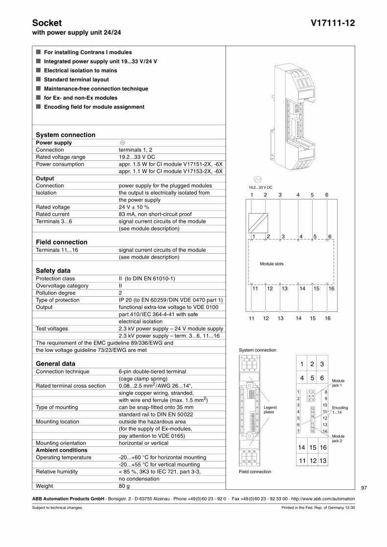
97
ABB Automation Products GmbH · Borsigstr. 2 · D-63755 Alzenau · Phone +49(0)60 23 - 92 0 · Fax +49(0)60 23 - 92 33 00 · http://www.abb.com/automation
Subject to technical changes. Printed in the Fed. Rep. of Germany 12.00
Socket V17111-12with power supply unit 24/24
For installing Contrans I modules
Integrated power supply unit 19...33 V/24 V
Electrical isolation to mains
Standard terminal layout
Maintenance-free connection technique
for Ex- and non-Ex modules
Encoding field for module assignment
System connectionPower supplyConnection terminals 1, 2Rated voltage range 19.2...33 V DCPower consumption appr. 1.5 W for CI module V17151-2X, -6X
appr. 1.1 W for CI module V17153-2X, -6XOutputConnection power supply for the plugged modulesIsolation the output is electrically isolated from
the power supplyRated voltage 24 V ± 10 %Rated current 83 mA, non short-circuit proofTerminals 3...6 signal current circuits of the module
(see module description)
Field connectionTerminals 11...16 signal current circuits of the module
(see module description)
Safety dataProtection class II (to DIN EN 61010-1)Overvoltage category IIPollution degree 2Type of protection IP 20 (to EN 60259/DIN VDE 0470 part 1)Output functional extra-low voltage to VDE 0100
part 410/IEC 364-4-41 with safeelectrical isolation
Test voltages 2.3 kV power supply – 24 V module supply2.3 kV power supply – term. 3...6, 11...16
The requirement of the EMC guideline 89/336/EWG andthe low voltage guideline 73/23/EWG are met
General dataConnection technique 6-pin double-tiered terminal
(cage clamp spring)Rated terminal cross section 0.08...2.5 mm2/AWG 26...14“,
single copper wiring, stranded,with wire end ferrule (max. 1.5 mm2)
Type of mounting can be snap-fitted onto 35 mmstandard rail to DIN EN 50022
Mounting location outside the hazardous area(for the supply of Ex-modules,pay attention to VDE 0165)
Mounting orientation horizontal or verticalAmbient conditionsOperating temperature -20...+60 °C for horizontal mounting
-20...+55 °C for vertical mountingRelative humidity < 85 %, 3K3 to IEC 721, part 3-3,
no condensationWeight 80 g
1
1
2
3
4
5
6
7
8
9
10
11
12
13
14
14
2
15
3
16
4
11
5
12
6
13
1
3
4
2
6
12
11
16
15
13
14
5
1
14
2
15
3
16
4
11
5
12
6
13
System connection
Field connection
Legendplates
Modulejack 1
Modulejack 2
Encoding1...14
1
1
11
11
2
2
12
12
3
3
13
13
4
4
14
14
5
5
15
15
6
6
16
16
Module slots
19,2...33 V DC
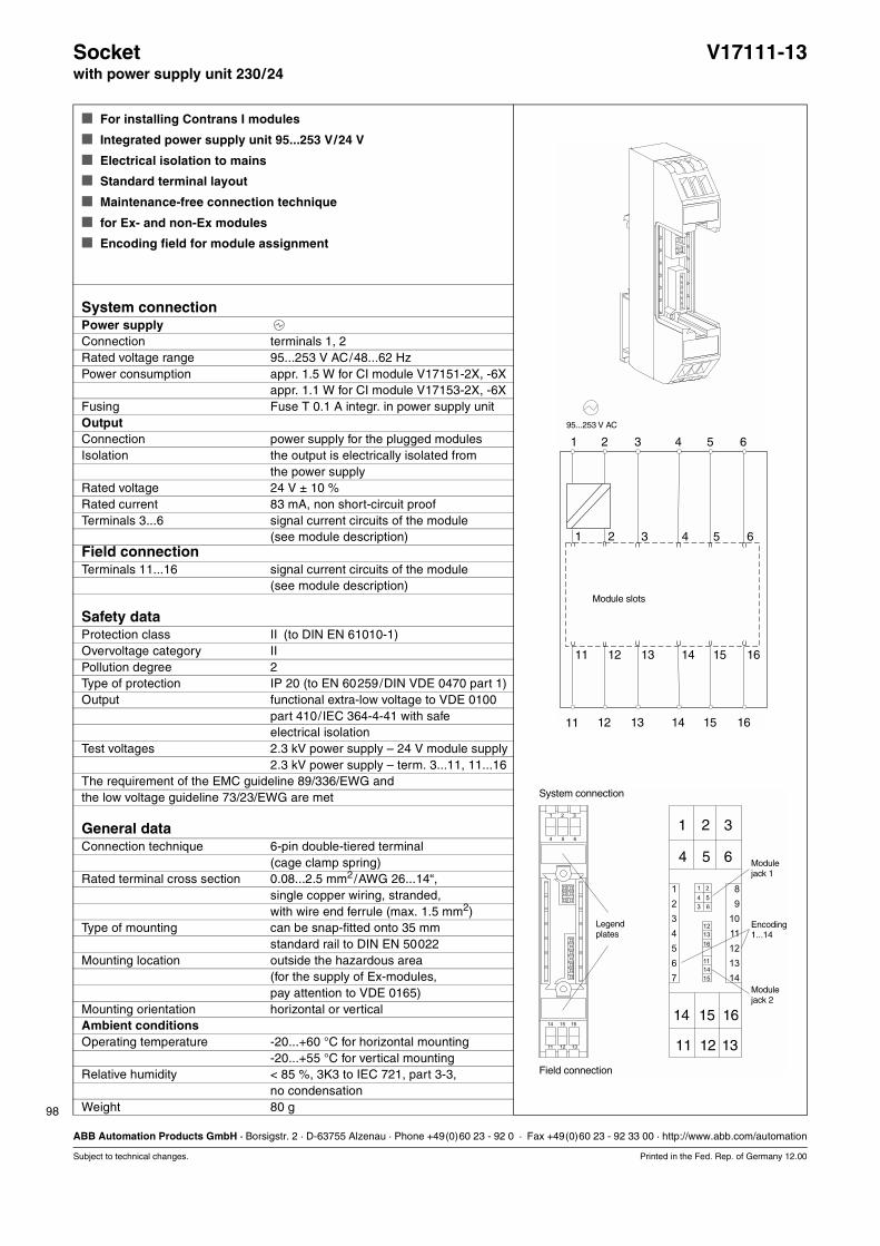
98
ABB Automation Products GmbH · Borsigstr. 2 · D-63755 Alzenau · Phone +49(0)60 23 - 92 0 · Fax +49(0)60 23 - 92 33 00 · http://www.abb.com/automation
Subject to technical changes. Printed in the Fed. Rep. of Germany 12.00
Socket V17111-13with power supply unit 230/24
For installing Contrans I modules
Integrated power supply unit 95...253 V/24 V
Electrical isolation to mains
Standard terminal layout
Maintenance-free connection technique
for Ex- and non-Ex modules
Encoding field for module assignment
System connectionPower supplyConnection terminals 1, 2Rated voltage range 95...253 V AC/48...62 HzPower consumption appr. 1.5 W for CI module V17151-2X, -6X
appr. 1.1 W for CI module V17153-2X, -6XFusing Fuse T 0.1 A integr. in power supply unitOutputConnection power supply for the plugged modulesIsolation the output is electrically isolated from
the power supplyRated voltage 24 V ± 10 %Rated current 83 mA, non short-circuit proofTerminals 3...6 signal current circuits of the module
(see module description)Field connectionTerminals 11...16 signal current circuits of the module
(see module description)
Safety dataProtection class II (to DIN EN 61010-1)Overvoltage category IIPollution degree 2Type of protection IP 20 (to EN 60259/DIN VDE 0470 part 1)Output functional extra-low voltage to VDE 0100
part 410/IEC 364-4-41 with safeelectrical isolation
Test voltages 2.3 kV power supply – 24 V module supply2.3 kV power supply – term. 3...11, 11...16
The requirement of the EMC guideline 89/336/EWG andthe low voltage guideline 73/23/EWG are met
General dataConnection technique 6-pin double-tiered terminal
(cage clamp spring)Rated terminal cross section 0.08...2.5 mm2/AWG 26...14“,
single copper wiring, stranded,with wire end ferrule (max. 1.5 mm2)
Type of mounting can be snap-fitted onto 35 mmstandard rail to DIN EN 50022
Mounting location outside the hazardous area(for the supply of Ex-modules,pay attention to VDE 0165)
Mounting orientation horizontal or verticalAmbient conditionsOperating temperature -20...+60 °C for horizontal mounting
-20...+55 °C for vertical mountingRelative humidity < 85 %, 3K3 to IEC 721, part 3-3,
no condensationWeight 80 g
1
1
2
3
4
5
6
7
8
9
10
11
12
13
14
14
2
15
3
16
4
11
5
12
6
13
1
3
4
2
6
12
11
16
15
13
14
5
1
14
2
15
3
16
4
11
5
12
6
13
System connection
Field connection
Legendplates
Modulejack 1
Modulejack 2
Encoding1...14
1
1
11
11
2
2
12
12
3
3
13
13
4
4
14
14
5
5
15
15
6
6
16
16
Module slots
95...253 V AC
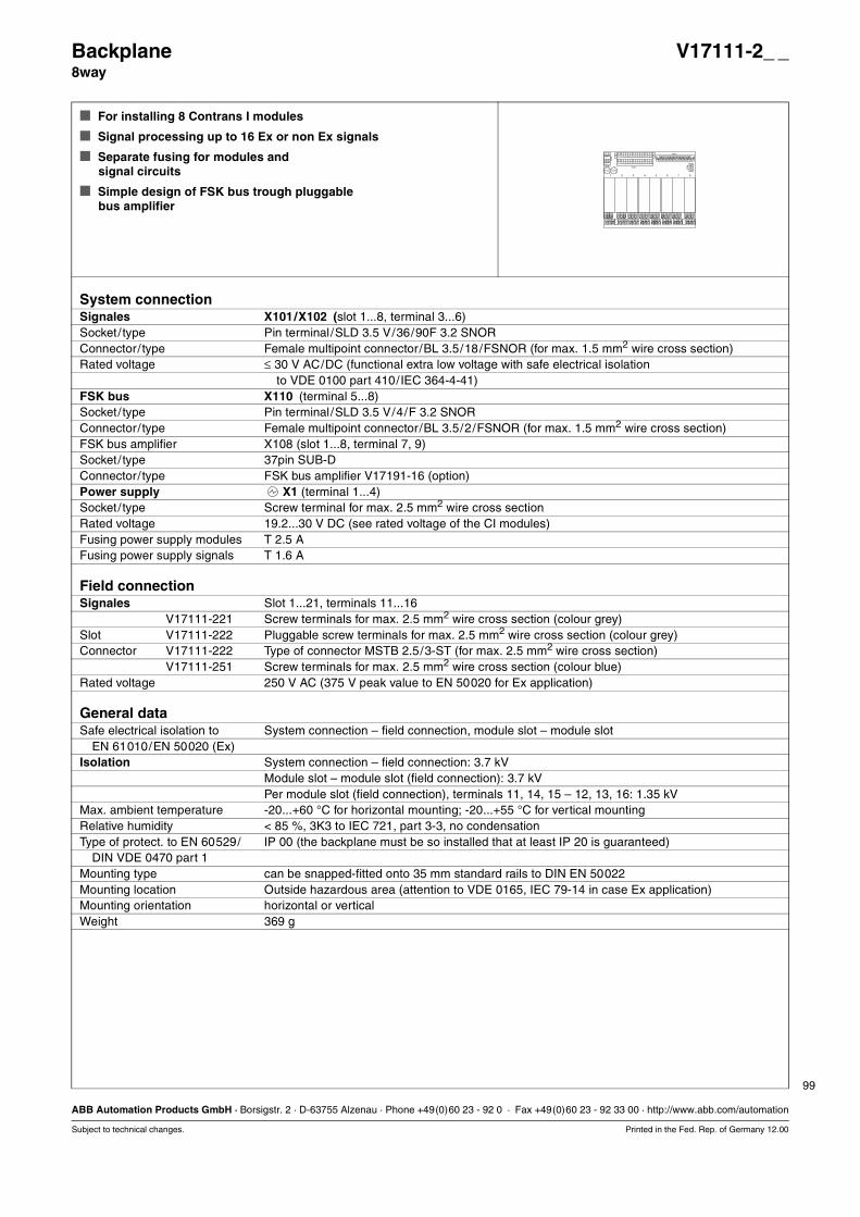
99
ABB Automation Products GmbH · Borsigstr. 2 · D-63755 Alzenau · Phone +49(0)60 23 - 92 0 · Fax +49(0)60 23 - 92 33 00 · http://www.abb.com/automation
Subject to technical changes. Printed in the Fed. Rep. of Germany 12.00
Backplane V17111-2_ _8way
For installing 8 Contrans I modules
Signal processing up to 16 Ex or non Ex signals
Separate fusing for modules andsignal circuits
Simple design of FSK bus trough pluggablebus amplifier
System connectionSignales X101/X102 (slot 1...8, terminal 3...6)Socket/ type Pin terminal/SLD 3.5 V/36/90F 3.2 SNORConnector/ type Female multipoint connector/BL 3.5/18/FSNOR (for max. 1.5 mm2 wire cross section)Rated voltage ≤ 30 V AC/DC (functional extra low voltage with safe electrical isolation
to VDE 0100 part 410/IEC 364-4-41)FSK bus X110 (terminal 5...8)Socket/ type Pin terminal/SLD 3.5 V/4/F 3.2 SNORConnector/ type Female multipoint connector/BL 3.5/2/FSNOR (for max. 1.5 mm2 wire cross section)FSK bus amplifier X108 (slot 1...8, terminal 7, 9)Socket/ type 37pin SUB-DConnector/ type FSK bus amplifier V17191-16 (option)Power supply X1 (terminal 1...4)Socket/ type Screw terminal for max. 2.5 mm2 wire cross sectionRated voltage 19.2...30 V DC (see rated voltage of the CI modules)Fusing power supply modules T 2.5 AFusing power supply signals T 1.6 A
Field connectionSignales Slot 1...21, terminals 11...16Slot V17111-221 Screw terminals for max. 2.5 mm2 wire cross section (colour grey)Slot V17111-222 Pluggable screw terminals for max. 2.5 mm2 wire cross section (colour grey)Connector V17111-222 Type of connector MSTB 2.5/3-ST (for max. 2.5 mm2 wire cross section)
V17111-251 Screw terminals for max. 2.5 mm2 wire cross section (colour blue)Rated voltage 250 V AC (375 V peak value to EN 50020 for Ex application)
General dataSafe electrical isolation to System connection – field connection, module slot – module slot
EN 61010/EN 50020 (Ex)Isolation System connection – field connection: 3.7 kV
Module slot – module slot (field connection): 3.7 kVPer module slot (field connection), terminals 11, 14, 15 – 12, 13, 16: 1.35 kV
Max. ambient temperature -20...+60 °C for horizontal mounting; -20...+55 °C for vertical mountingRelative humidity < 85 %, 3K3 to IEC 721, part 3-3, no condensationType of protect. to EN 60529/ IP 00 (the backplane must be so installed that at least IP 20 is guaranteed)
DIN VDE 0470 part 1Mounting type can be snapped-fitted onto 35 mm standard rails to DIN EN 50022Mounting location Outside hazardous area (attention to VDE 0165, IEC 79-14 in case Ex application)Mounting orientation horizontal or verticalWeight 369 g
11 12 13
14 15 16
11 12 13
14 15 16
11 12 13
14 15 16
11 12 13
14 15 16
11 12 13
14 15 16
11 12 13
14 15 16
11 12 13
14 15 16
11 12 13
14 15 16
T1,6A T2,5A
X103
X10
4
X10
2
24VDCX101
1 21.
31.
62.
32.
63.
33.
64.
34.
65.
35.
66.
36.
67.
37.
68.
38.
6
1 21.
41.
52.
42.
53.
43.
54.
44.
55.
45.
56.
46.
57.
47.
58.
48.
5
1
2
5656
+ -
1 2
1 2
+ -
7 864 5321

100
ABB Automation Products GmbH · Borsigstr. 2 · D-63755 Alzenau · Phone +49(0)60 23 - 92 0 · Fax +49(0)60 23 - 92 33 00 · http://www.abb.com/automation
Subject to technical changes. Printed in the Fed. Rep. of Germany 12.00
Backplane V17111-2_ _8way
11 12 13
14 15 16
11 12 13
14 15 16
11 12 13
14 15 16
11 12 13
14 15 16
11 12 13
14 15 16
11 12 13
14 15 16
11 12 13
14 15 16
11 12 13
14 15 16
T1,6A T2,5A
X108
X110
X1
X101
X102
24VDC
1 2 1.4
1.5
2.4
2.5
3.4
3.5
4.4
4.5
5.4
5.5
6.4
6.5
7.4
7.5
8.4
8.5
1 2 1.3
1.6
2.3
2.6
3.3
3.6
4.3
4.6
5.3
5.6
6.3
6.6
7.3
7.6
8.3
8.6
1 2
1.3
1.6
2.3
2.6
3.3
3.6
4.3
4.6
5.3
5.6
6.3
6.6
7.3
7.6
8.3
8.6
1 2
1.4
1.5
2.4
2.5
3.4
3.5
4.4
4.5
5.4
5.5
6.4
6.5
7.4
7.5
8.4
8.5
1
2
5
6
7
8
+ -
1 2
3 4
+ -
1 2 3 4 5 6 7 8
Field connection
Slot forFSK bus amplifier
Power supply
FS
K b
us
System connection
Signals, slot 1...8
Signals, slot 1...8
connector X101slot 1...8channel 1
X101channel 1
X102channel 2
connector X102slot 1...8channel 2
slot 1/4(+) slot 1/3(+)
slot 1/5(-) slot 1/6(-)slot 2/4(+) slot 2/3(+)slot 2/5(-) slot 2/6(-)slot 3/4(+) slot 3/3(+)slot 3/5(-) slot 3/6(-)slot 4/4(+) slot 4/3(+)slot 4/5(-) slot 4/6(-)slot 5/4(+) slot 5/3(+)slot 5/5(-) slot 5/6(-)slot 6/4(+) slot 6/3(+)
slot 6/5(-) slot 6/6(-)slot 7/4(+) slot 7/3(+)slot 7/5(-) slot 7/6(-)slot 8/4(+) slot 8/3(+)slot 8/5(-) slot 8/6(-)
+ 24 V + 24 V
0 V 0 V
1 2 5 6
1 2 54 3 6
3 4 7 81 2.41.4 3.42 2.51.5 . . .
11 1513 1612 14
36 217 437 318 19 1 . . .
X1 X102X101 X108 X110+24V +24V
T2,5AT1,6A
0 V 0 V +24V0 V 0 V
7 8 109
3.5 1 2.31.3 3.32 2.61.6 . . .3.6
+24V 0 V +24V 0 V
5
Power supply FSK bus amplifier FSK bus
Contrans Imodules
System connection
Field connection
slot 1...8, channel 1 slot 1...8, channel 2
123456789
10111213141516171819
202122232425262728293031323334353637
X108slot
FSK bus amplifier
slot 1/7slot 1/9
slot 2/7slot 2/9
slot 3/7slot 3/9
slot 4/7slot 4/9
slot 5/7slot 5/9slot 6/7slot 6/9
slot 7/7slot 7/9
slot 8/7slot 8/9
+ 24 VGNDGND
X 110/6X 110/5
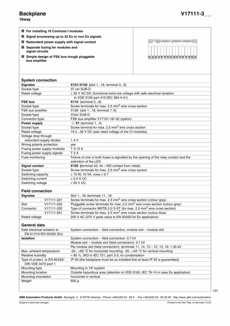
101
ABB Automation Products GmbH · Borsigstr. 2 · D-63755 Alzenau · Phone +49(0)60 23 - 92 0 · Fax +49(0)60 23 - 92 33 00 · http://www.abb.com/automation
Subject to technical changes. Printed in the Fed. Rep. of Germany 12.00
Backplane V17111-3_ _16way
For installing 16 Contrans I modules
Signal processing up to 32 Ex or non Ex signals
Redundant power supply with signal contact
Separate fusing for modules andsignal circuits
Simple design of FSK bus trough pluggablebus amplifier
System connectionSignales X101/X102 (slot 1...16, terminal 3...6)Socket/ type 37 oin SUB-DRated voltage ≤ 30 V AC/DC (functional extra low voltage with safe electrical isolation
to VDE 0100 part 410/IEC 364-4-41)FSK bus X110 (terminal 5...8)Socket/ type Screw terminals for max. 2.5 mm2 wire cross sectionFSK bus amplifier X108 (slot 1...16, terminal 7, 9)Socket/ type 37pin SUB-DConnector/ type FSK bus amplifier V17191-16/-32 (option)Power supply X1 (terminal 1...4)Socket/ type Screw terminal for max. 2.5 mm2 wire cross sectionRated voltage 19.2...30 V DC (see rated voltage of the CI modules)Voltage drop through
redundant supply diodes 1.4 VWrong polarity protection yesFusing power supply modules T 3.15 AFusing power supply signals T 2 AFuse monitoring Failure of one or both fuses is signalled by the opening of the relay contact and the
extinction of the LEDSignal contact X105 (terminal 43, 44 – NO contact from relais)Socket/ type Screw terminals for max. 2.5 mm2 wire cross sectionSwitching capacity ≤ 10 W, 10 VA, cosϕ ≥ 0.7Switching current ≤ 0.5 A UCSwitching voltage ≤ 50 V UC
Field connectionSignales Slot 1...16, terminals 11...16
V17111-331 Screw terminals for max. 2.5 mm2 wire cross section (colour grey)Slot V17111-332 Pluggable screw terminals for max. 2.5 mm2 wire cross section (colour grey)Connector V17111-332 Type of connector MSTB 2.5/3-ST (for max. 2.5 mm2 wire cross section)
V17111-351 Screw terminals for max. 2.5 mm2 wire cross section (colour blue)Rated voltage 250 V AC (375 V peak value to EN 50020 for Ex application)
General dataSafe electrical isolation to System connection – field connection, module slot – module slot
EN 61010/EN 50020 (Ex)Isolation System connection – field connection: 3.7 kV
Module slot – module slot (field connection): 3.7 kVPer module slot (field connection), terminals 11, 14, 15 – 12, 13, 16: 1.35 kV
Max. ambient temperature -20...+60 °C for horizontal mounting; -20...+55 °C for vertical mountingRelative humidity < 85 %, 3K3 to IEC 721, part 3-3, no condensationType of protect. to EN 60529/ IP 00 (the backplane must be so installed that at least IP 20 is guaranteed)
DIN VDE 0470 part 1Mounting type Mounting in 19“-systemMounting location Outside hazardous area (attention to VDE 0165, IEC 79-14 in case Ex application)Mounting orientation horizontal or verticalWeight 600 g
3 54 6
16151412
1 1 432 2 44
+ - + -24 VDC K101X101 X102 X108
T2,5A T1,6A
13111097 864 5321
FSKFSK
11 12 13
14 15 16
11 12 13
14 15 16
11 12 13
14 15 16
11 12 13
14 15 16
11 12 13
14 15 16
11 12 13
14 15 16
11 12 13
14 15 16
11 12 13
14 15 16
11 12 13
14 15 16
11 12 13
14 15 16
11 12 13
14 15 16
11 12 13
14 15 16
11 12 13
14 15 16
11 12 13
14 15 16
11 12 13
14 15 16
11 12 13
14 15 16
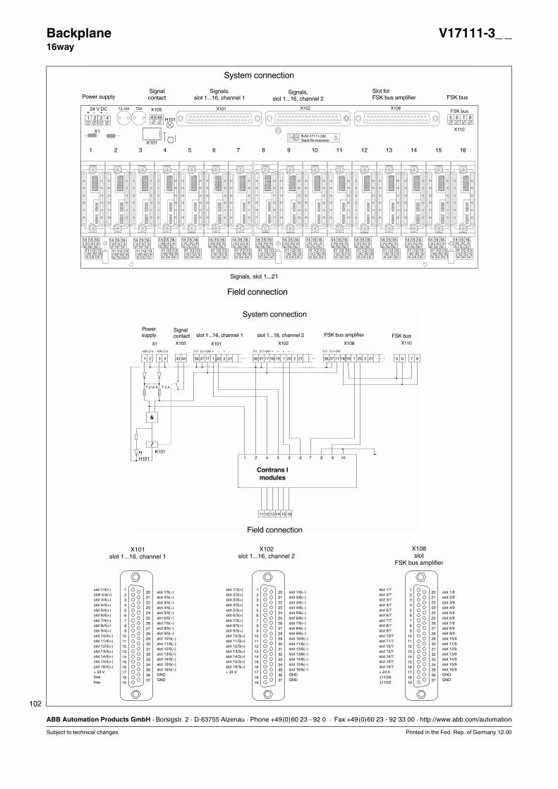
102
ABB Automation Products GmbH · Borsigstr. 2 · D-63755 Alzenau · Phone +49(0)60 23 - 92 0 · Fax +49(0)60 23 - 92 33 00 · http://www.abb.com/automation
Subject to technical changes. Printed in the Fed. Rep. of Germany 12.00
Backplane V17111-3_ _16way
16151412
X101 X102 X108T3,15A T2A
13111097 864 5321
B-Nr:17111-330Sach-Nr:xxxxxxxx
11 12 13
14 15 16
11 12 13
14 15 16
11 12 13
14 15 16
11 12 13
14 15 16
11 12 13
14 15 16
11 12 13
14 15 16
11 12 13
14 15 16
11 12 13
14 15 16
11 12 13
14 15 16
11 12 13
14 15 16
11 12 13
14 15 16
11 12 13
14 15 16
11 12 13
14 15 16
11 12 13
14 15 16
11 12 13
14 15 16
11 12 13
14 15 16
1 2
+ - + -
3 4
X1
X105
H101
X110
FSK bus
5 6 7 843 44
24 V DC
K101
Power supplySignalcontact
Field connection
Slot forFSK bus amplifier FSK bus
Signals,slot 1...16, channel 1
Signals,slot 1...16, channel 2
System connection
Signals, slot 1...21
1 2 5 6
1 2 54 3 6
3 4 7 843 44 36 2017 2137 21 . . .
11 1513 1612 14
36 2017 2137 218 19 1 . . .
X1 X105
K101
H101
X101 X102 X108 X110
/
T 3,15 A T 2 A
&
+24V +24V 0 V 0 V 0 V0 V 0 V 0 V+24V +24V +24V+ ++ +– –– –0 V 0 V
7 8 109
36 2017 2137 218 19 1 . . .
Contrans Imodules
Powersupply
Signalcontact
System connection
FSK bus amplifierslot 1...16, channel 1 slot 1...16, channel 2 FSK bus
Field connection
123456789
10111213141516171819
202122232425262728293031323334353637
123456789
10111213141516171819
202122232425262728293031323334353637
123456789
10111213141516171819
202122232425262728293031323334353637
slot 1/3(+)slot 1/6(–)
slot 2/3(+)slot 2/6(–)
slot 3/3(+)slot 3/6(–)
slot 4/3(+)slot 4/6(–)
slot 5/3(+)slot 5/6(–)
slot 6/3(+)slot 6/6(–)
slot 7/3(+)slot 7/6(–)
slot 8/3(+)slot 8/6(–)
slot 9/3(+)slot 9/6(–)
slot 10/3(+)slot 10/6(–)
slot 11/3(+)slot 11/6(–)
slot 12/3(+)slot 12/6(–)
slot 13/3(+)slot 13/6(–)
slot 14/3(+)slot 14/6(–)
slot 15/3(+)slot 15/6(–)
slot 16/3(+)slot 16/6(–)
+ 24 VGNDGND
X101slot 1...16, channel 1
X102slot 1...16, channel 2
X108slot
FSK bus amplifier
slot 1/4(+)slot 1/5(–)
slotl 2/4(+)slot 2/5(–)
slot 3/4(+)slot 3/5(–)
slot 4/4(+)slot 4/5(–)
slot 5/4(+)slot 5/5(–)
slot 6/4(+)slot 6/5(–)
slot 7/4(+)slot 7/5(–)
slot 8/4(+)slot 8/5(–)
slot 9/4(+)slot 9/5(–)
slot 10/4(+)slot 10/5(–)
slot 11/4(+)slot 11/5(–)
slot 12/4(+)slot 12/5(–)
slot 13/4(+)slot 13/5(–)
slot 14/4(+)slot 14/5(–)
slot 15/4(+)slot 15/5(–)
slot 16/4(+)slot 16/5(–)
+ 24 VGND
freeGND
free
slot 1/7slot 1/9
slot 2/7slot 2/9
slot 3/7slot 3/9
slot 4/7slot 4/9
slot 5/7slot 5/9
slot 6/7slot 6/9
slot 7/7slot 7/9
slot 8/7slot 8/9
slot 9/7slot 9/9
slot 10/7slot 10/9
slot 11/7slot 11/9
slot 12/7slot 12/9
slot 13/7slot 13/9
slot 14/7slot 14/9
slot 15/7slot 15/9
slot 16/7slot 16/9
+ 24 VGNDGND
x110/6x110/5
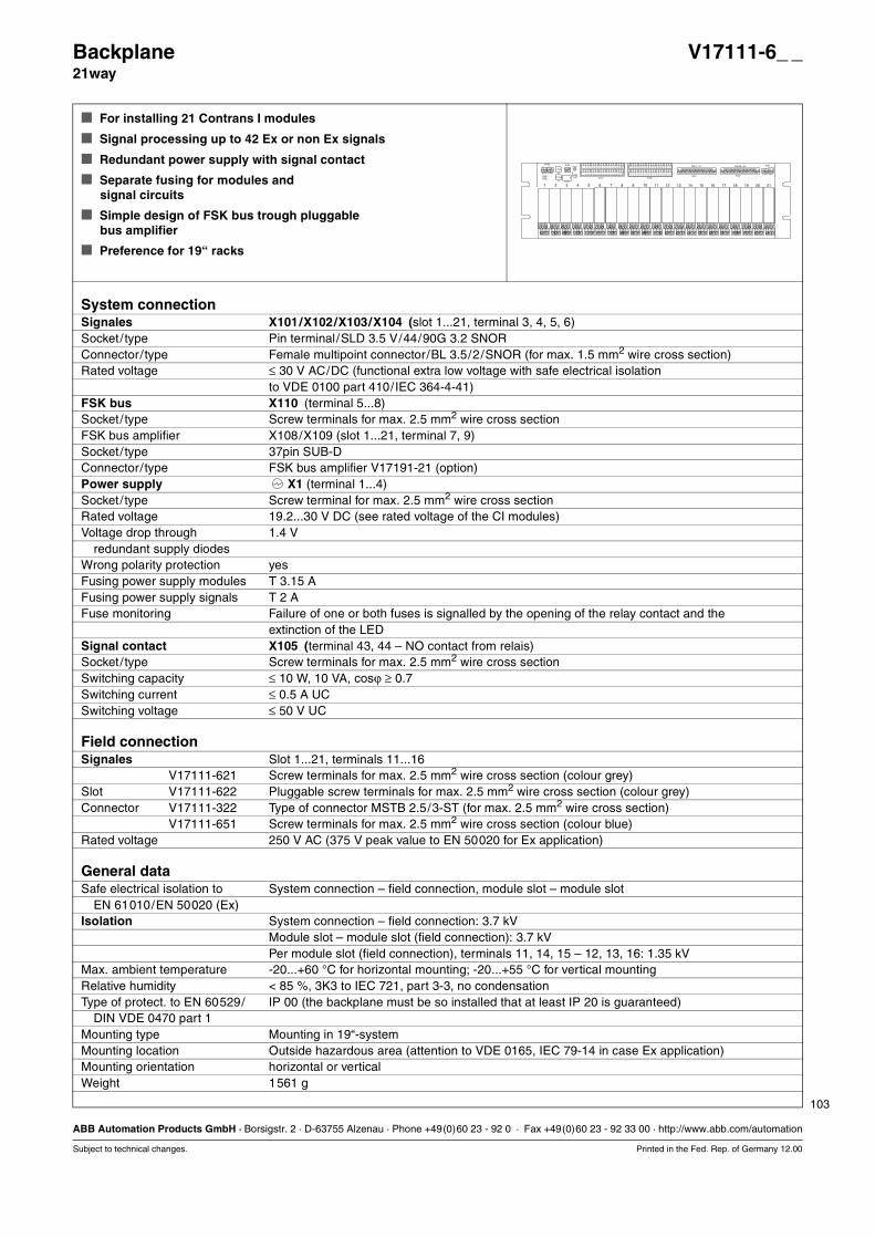
103
ABB Automation Products GmbH · Borsigstr. 2 · D-63755 Alzenau · Phone +49(0)60 23 - 92 0 · Fax +49(0)60 23 - 92 33 00 · http://www.abb.com/automation
Subject to technical changes. Printed in the Fed. Rep. of Germany 12.00
Backplane V17111-6_ _21way
For installing 21 Contrans I modules
Signal processing up to 42 Ex or non Ex signals
Redundant power supply with signal contact
Separate fusing for modules andsignal circuits
Simple design of FSK bus trough pluggablebus amplifier
Preference for 19“ racks
System connectionSignales X101/X102/X103/X104 (slot 1...21, terminal 3, 4, 5, 6)Socket/ type Pin terminal/SLD 3.5 V/44/90G 3.2 SNORConnector/ type Female multipoint connector/BL 3.5/2/SNOR (for max. 1.5 mm2 wire cross section)Rated voltage ≤ 30 V AC/DC (functional extra low voltage with safe electrical isolation
to VDE 0100 part 410/IEC 364-4-41)FSK bus X110 (terminal 5...8)Socket/ type Screw terminals for max. 2.5 mm2 wire cross sectionFSK bus amplifier X108/X109 (slot 1...21, terminal 7, 9)Socket/ type 37pin SUB-DConnector/ type FSK bus amplifier V17191-21 (option)Power supply X1 (terminal 1...4)Socket/ type Screw terminal for max. 2.5 mm2 wire cross sectionRated voltage 19.2...30 V DC (see rated voltage of the CI modules)Voltage drop through 1.4 V
redundant supply diodesWrong polarity protection yesFusing power supply modules T 3.15 AFusing power supply signals T 2 AFuse monitoring Failure of one or both fuses is signalled by the opening of the relay contact and the
extinction of the LEDSignal contact X105 (terminal 43, 44 – NO contact from relais)Socket/ type Screw terminals for max. 2.5 mm2 wire cross sectionSwitching capacity ≤ 10 W, 10 VA, cosϕ ≥ 0.7Switching current ≤ 0.5 A UCSwitching voltage ≤ 50 V UC
Field connectionSignales Slot 1...21, terminals 11...16
V17111-621 Screw terminals for max. 2.5 mm2 wire cross section (colour grey)Slot V17111-622 Pluggable screw terminals for max. 2.5 mm2 wire cross section (colour grey)Connector V17111-322 Type of connector MSTB 2.5/3-ST (for max. 2.5 mm2 wire cross section)
V17111-651 Screw terminals for max. 2.5 mm2 wire cross section (colour blue)Rated voltage 250 V AC (375 V peak value to EN 50020 for Ex application)
General dataSafe electrical isolation to System connection – field connection, module slot – module slot
EN 61010/EN 50020 (Ex)Isolation System connection – field connection: 3.7 kV
Module slot – module slot (field connection): 3.7 kVPer module slot (field connection), terminals 11, 14, 15 – 12, 13, 16: 1.35 kV
Max. ambient temperature -20...+60 °C for horizontal mounting; -20...+55 °C for vertical mountingRelative humidity < 85 %, 3K3 to IEC 721, part 3-3, no condensationType of protect. to EN 60529/ IP 00 (the backplane must be so installed that at least IP 20 is guaranteed)
DIN VDE 0470 part 1Mounting type Mounting in 19“-systemMounting location Outside hazardous area (attention to VDE 0165, IEC 79-14 in case Ex application)Mounting orientation horizontal or verticalWeight 1561 g
11 12 13
14 15 16
11 12 13
14 15 16
11 12 13
14 15 16
11 12 13
14 15 16
11 12 13
14 15 16
11 12 13
14 15 16
11 12 13
14 15 16
11 12 13
14 15 16
11 12 13
14 15 16
11 12 13
14 15 16
11 12 13
14 15 16
11 12 13
14 15 16
11 12 13
14 15 16
11 12 13
14 15 16
11 12 13
14 15 16
11 12 13
14 15 16
11 12 13
14 15 16
11 12 13
14 15 16
11 12 13
14 15 16
11 12 13
14 15 16
11 12 13
14 15 16
1 2+ - + -
3 4
X103 X104
X105H101
X301X102
FSK 1...21 FSK 22...42
X302X106
FSK
X107
5 5 6 643 44
T3,15A
T2A
X101
1 2 1.3
1.6
2.3
2.6
3.3
3.6
4.3
4.6
5.3
5.6
6.3
6.6
7.3
7.6
8.3
8.6
9.3
9.6
10.3
10.6
11.3
11.6
12.3
12.6
13.3
13.6
14.3
14.6
15.3
15.6
16.3
16.6
17.3
17.6
18.3
18.6
19.3
19.6
20.3
20.6
21.3
21.6
1 2 1.4
1.5
2.4
2.5
3.4
3.5
4.4
4.5
5.4
5.5
6.4
6.5
7.4
7.5
8.4
8.5
9.4
9.5
10.4
10.5
11.4
11.5
12.4
12.5
13.4
13.5
14.4
14.5
15.4
15.5
16.4
16.5
17.4
17.5
18.4
18.5
19.4
19.5
20.4
20.5
21.4
21.5
24VDC
K101
1 2 3 4 5 6 7 8 9 10 11 12 13 14 15 16 17 18 19 20 21
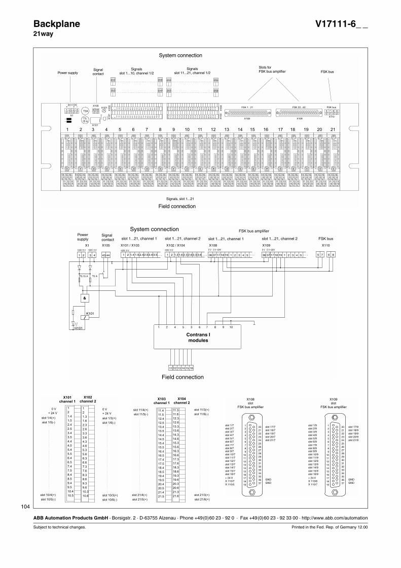
104
ABB Automation Products GmbH · Borsigstr. 2 · D-63755 Alzenau · Phone +49(0)60 23 - 92 0 · Fax +49(0)60 23 - 92 33 00 · http://www.abb.com/automation
Subject to technical changes. Printed in the Fed. Rep. of Germany 12.00
Backplane V17111-6_ _21way
11 12 13
14 15 16
11 12 13
14 15 16
11 12 13
14 15 16
11 12 13
14 15 16
11 12 13
14 15 16
11 12 13
14 15 16
11 12 13
14 15 16
11 12 13
14 15 16
11 12 13
14 15 16
11 12 13
14 15 16
11 12 13
14 15 16
11 12 13
14 15 16
11 12 13
14 15 16
11 12 13
14 15 16
11 12 13
14 15 16
11 12 13
14 15 16
11 12 13
14 15 16
11 12 13
14 15 16
11 12 13
14 15 16
11 12 13
14 15 16
11 12 13
14 15 16
1 2
+ - + -
3 4
X1
X105H101
X108
X102
X104
FSK 1...21 FSK 22...42
X109X110
5 7 6 843 44
T3,15 A
T2AX
101
X103
1 2 1.3
1.6
2.3
2.6
3.3
3.6
4.3
4.6
5.3
5.6
6.3
6.6
7.3
7.6
8.3
8.6
9.3
9.6
10.3
10.6
11.3
11.6
12.3
12.6
13.3
13.6
14.3
14.6
15.3
15.6
16.3
16.6
17.3
17.6
18.3
18.6
19.3
19.6
20.3
20.6
21.3
21.6
1 2 1.4
1.5
2.4
2.5
3.4
3.5
4.4
4.5
5.4
5.5
6.4
6.5
7.4
7.5
8.4
8.5
9.4
9.5
10.4
10.5
11.4
11.5
12.4
12.5
13.4
13.5
14.4
14.5
15.4
15.5
16.4
16.5
17.4
17.5
18.4
18.5
19.4
19.5
20.4
20.5
21.4
21.5
24 V DC
K101
1 2 3 4 5 6 7 8 9 10 11 12 13 14 15 16 17 18 19 20 21
Power supplySignalcontact
Slots forFSK bus amplifier FSK bus
Signalsslot 1...10, channel 1/2
Signalsslot 11...21, channel 1/2
Signals, slot 1...21
System connection
Field connection
FSK bus
5 6
1 2 54 3 6
7 81 2.41.4 3.42 2.51.5 . . .
11 1513 1612 14
36 362 217 174 437 373 318 1819 191 1. . . . . .
X102 / X104X101 / X103 X108 X109 X1100 V 0 V0 V 0 V+24V +24V
7 8 109
3.5 1 2.31.3 3.32 2.61.6 . . .3.6
+24V 0 V +24V 0 V
5 51 2 3 4 43 44
X1 X105
K101
H101
/
T3,15 A T2 A
&
+24V +24V0 V 0 V
Powersupply
Signalcontact FSK bus
Contrans Imodules
System connection
Field connection
slot 1...21, channel 1 slot 1...21, channel 2
FSK bus amplifier
slot 1...21, channel 1 slot 1...21, channel 2
1
2
1.3
1.6
2.3
2.6
3.3
3.6
4.3
4.6
5.3
5.6
6.3
6.6
7.3
7.6
8.3
8.6
9.3
9.6
10.3
10.6
1
2
1.4
1.5
2.4
2.5
3.4
3.5
4.4
4.5
5.4
5.5
6.4
6.5
7.4
7.5
8.4
8.5
9.4
9.5
10.4
10.5
slot 1/4(+)
slot 10/4(+)
slot 1/5(-)
slot 10/5(-)
+ 24 V
0 V
X101
channel 1
X102
channel 2
slot 1/3(+)
slot 10/3(+)
slot 1/6(-)
slot 10/6(-)
+ 24 V
0 V 11.3
11.6
12.3
12.6
13.3
13.6
14.3
14.6
15.3
15.6
16.3
16.6
17.3
17.6
18.3
18.6
19.3
19.6
20.3
20.6
21.3
21.6
11.4
11.5
12.4
12.5
13.4
13.5
14.4
14.5
15.4
15.5
16.4
16.5
17.4
17.5
18.4
18.5
19.4
19.5
20.4
20.5
21.4
21.5
slot 11/3(+)
slot 21/3(+)
slot 21/6(+)
slot 11/6(-)
slot 11/4(+)
slot 21/4(+)
slot 21/5(+)
slot 11/5(-)
X103
channel 1
X104
channel 2
123456789
10111213141516171819
202122232425262728293031323334353637
123456789
10111213141516171819
202122232425262728293031323334353637
X108slot
FSK bus amplifier
X109slot
FSK bus amplifier
slot 1/7 slot 1/9
slot 9/7 slot 9/9
slot 17/7 slot 17/9slot 2/7 slot 2/9
slot 10/7 slot 10/9
slot 18/7 slot 18/9slot 3/7 slot 3/9
slot 11/7 slot 11/9
slot 19/7 slot 19/9slot 4/7 slot 4/9
slot 12/7 slot 12/9
slot 20/7 slot 20/9slot 5/7 slot 5/9
slot 13/7 slot 13/9
slot 21/7 slot 21/9slot 6/7 slot 6/9
slot 14/7 slot 14/9
slot 7/7 slot 7/9
slot 15/7 slot 15/9
slot 8/7 slot 8/9
slot 16/7 slot 16/9+ 24 V + 24 V
GND GNDGND GND
X 110/7 X 110/6X 110/5 X 110/7
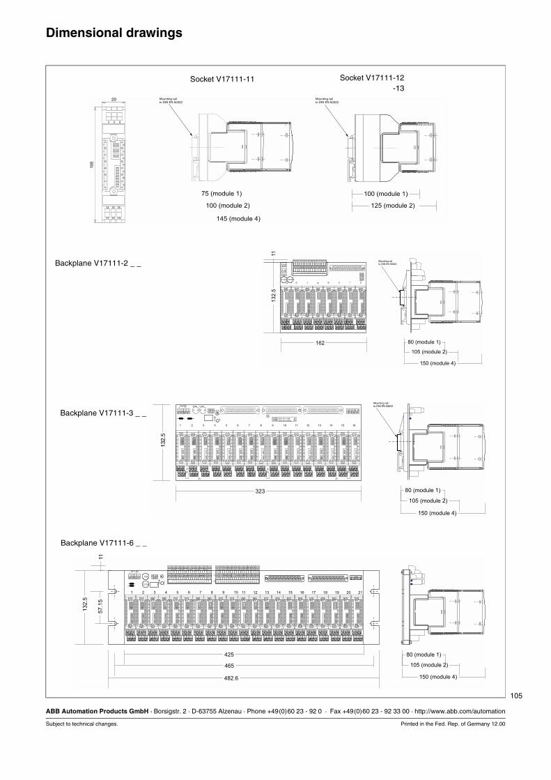
105
ABB Automation Products GmbH · Borsigstr. 2 · D-63755 Alzenau · Phone +49(0)60 23 - 92 0 · Fax +49(0)60 23 - 92 33 00 · http://www.abb.com/automation
Subject to technical changes. Printed in the Fed. Rep. of Germany 12.00
Dimensional drawings
Backplane V17111-2 _ _
Backplane V17111-3 _ _
Backplane V17111-6 _ _
Socket V17111-12Socket V17111-13
Socket V17111-11
13
2.5
162
11 12 13
14 15 16
11 12 13
14 15 16
11 12 13
14 15 16
11 12 13
14 15 16
11 12 13
14 15 16
11 12 13
14 15 16
11 12 13
14 15 16
11 12 13
14 15 16
T1,6A T2,5A
24VDC
1 2
1.3
1.6
2.3
2.6
3.3
3.6
4.3
4.6
5.3
5.6
6.3
6.6
7.3
7.6
8.3
8.6
1 2
1.4
1.5
2.4
2.5
3.4
3.5
4.4
4.5
5.4
5.5
6.4
6.5
7.4
7.5
8.4
8.5
1
2
5
6
5
6
+ -
1 2
1 2
+ -11
80 (module 1)
105 (module 2)
150 (module 4)
Mounting railto DIN EN 50022
16151412
T2,5A T1,6A
13111097 864 5321
B-Nr:17111-330Sach-Nr:xxxxxxxx
11 12 13
14 15 16
11 12 13
14 15 16
11 12 13
14 15 16
11 12 13
14 15 16
11 12 13
14 15 16
11 12 13
14 15 16
11 12 13
14 15 16
11 12 13
14 15 16
11 12 13
14 15 16
11 12 13
14 15 16
11 12 13
14 15 16
11 12 13
14 15 16
11 12 13
14 15 16
11 12 13
14 15 16
11 12 13
14 15 16
11 12 13
14 15 16
1 2
+ - + -
3 4 H101 5 5 6 643 44
24VDC
132.
5
323 80 (module 1)
105 (module 2)
150 (module 4)
Mounting railto DIN EN 50022
11 12 13
14 15 16
11 12 13
14 15 16
11 12 13
14 15 16
11 12 13
14 15 16
11 12 13
14 15 16
11 12 13
14 15 16
11 12 13
14 15 16
11 12 13
14 15 16
11 12 13
14 15 16
11 12 13
14 15 16
11 12 13
14 15 16
11 12 13
14 15 16
11 12 13
14 15 16
11 12 13
14 15 16
11 12 13
14 15 16
11 12 13
14 15 16
11 12 13
14 15 16
11 12 13
14 15 16
11 12 13
14 15 16
11 12 13
14 15 16
11 12 13
14 15 16
1 2
+ - + -
3 4 1
2
5 5 6 643 44
T3,15A
T2A
1 2 1.3
1.6
2.3
2.6
3.3
3.6
4.3
4.6
5.3
5.6
6.3
6.6
7.3
7.6
8.3
8.6
9.3
9.6
10.3
10.6
11.3
11.6
12.3
12.6
13.3
13.6
14.3
14.6
15.3
15.6
16.3
16.6
17.3
17.6
18.3
18.6
19.3
19.6
20.3
20.6
21.3
21.6
1 2 1.4
1.5
2.4
2.5
3.4
3.5
4.4
4.5
5.4
5.5
6.4
6.5
7.4
7.5
8.4
8.5
9.4
9.5
10.4
10.5
11.4
11.5
12.4
12.5
13.4
13.5
14.4
14.5
15.4
15.5
16.4
16.5
17.4
17.5
18.4
18.5
19.4
19.5
20.4
20.5
21.4
21.5
24 V DC
1 2 3 4 5 6 7 8 9 10 11 12 13 14 15 16 17 18 19 20 21
482.6
465
425
57
.15
13
2.5
11
80 (module 1)
105 (module 2)
150 (module 4)
105
20
4 5 6
14
11 12 13
15 16
Mounting railto DIN EN 50022
75 (module 1)
100 (module 2)
145 (module 4)
Mounting railto DIN EN 50022
100 (module 1)
125 (module 2)

Accessories
12.00 107
Cross Wiring Module V17191-11
Straight Through Module V17191-12
FSK Bus Amplifier 16, 21, 32 channels V17191-16, -21, -32
Programming Software for Contrans I 7957781
System Cables SUB D connector, single 0336935V
Power Supply V17212-1_0

108
ABB Automation Products GmbH · Borsigstr. 2 · D-63755 Alzenau · Phone +49(0)60 23 - 92 0 · Fax +49(0)60 23 - 92 33 00 · http://www.abb.com/automation
Subject to technical changes. Printed in the Fed. Rep. of Germany 12.00
Cross Wiring Module V17191-11
Connection multiplication
Various types of cabling
Routing of incoming and outgoing lines
Separation between intrinsically safe andnon-intrinsically safe circuits
Module size 2Module fits for:
Input Socket BackplaneConnection Terminals 12, 13, 14, 15, 16 V17111-11 V17111-2 _ _
intrinsically safe and V17111-12 V17111-3 _ _
non-intrinsically safe circuits V17111-13 V17111-6 _ _
Routing DIP switches S11...S17
OutputConnection Terminals 1, 2, 3, 4, 5, 6
non-intrinsically safe circuitsRouting jumpers S1...S7
1 2 3 4 5 6
S1 S3
S2 S5
S6
S7
S4
11 12 13 14 15 16
S17
S16
S15 S14S12
S11 S13
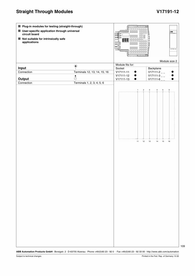
109
ABB Automation Products GmbH · Borsigstr. 2 · D-63755 Alzenau · Phone +49(0)60 23 - 92 0 · Fax +49(0)60 23 - 92 33 00 · http://www.abb.com/automation
Subject to technical changes. Printed in the Fed. Rep. of Germany 12.00
Straight Through Modules V17191-12
Plug-in modules for testing (straight-through)
User-specific application through universalcircuit board
Not suitable for intrinsically safeapplications
Module size 2Module fits for:
Input Socket BackplaneConnection Terminals 12, 13, 14, 15, 16 V17111-11 V17111-2 _ _
V17111-12 V17111-3 _ _
Output V17111-13 V17111-6 _ _
Connection Terminals 1, 2, 3, 4, 5, 6
1 2 3 4 5 6
11 12 13 14 15 16

110
ABB Automation Products GmbH · Borsigstr. 2 · D-63755 Alzenau · Phone +49(0)60 23 - 92 0 · Fax +49(0)60 23 - 92 33 00 · http://www.abb.com/automation
Subject to technical changes. Printed in the Fed. Rep. of Germany 12.00
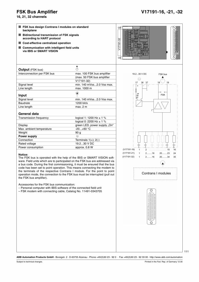
111
ABB Automation Products GmbH · Borsigstr. 2 · D-63755 Alzenau · Phone +49(0)60 23 - 92 0 · Fax +49(0)60 23 - 92 33 00 · http://www.abb.com/automation
Subject to technical changes. Printed in the Fed. Rep. of Germany 12.00
FSK Bus Amplifier V17191-16, -21, -3216, 21, 32 channels
FSK bus design Contrans I modules on standardbackplane
Bidirectional transmission of FSK signalsaccording to HART protocol
Cost-effective centralized operation
Communication with intelligent field unitsvia IBIS or SMART VISION
Output (FSK bus)Interconnection per FSK bus max. 100 FSK bus amplifier
(max. 50 FSK bus amplifierV17191-32)
Signal level min. 140 mVss...2.0 Vss max.Line length max. 1000 m
InputSignal level min. 140 mVss...2.0 Vss max.Baudrate 1200 bit/sLine length max. 2 m
General dataTransmission frequency logical 1: 1200 Hz ± 1 %
logical 0: 2200 Hz ± 1 %Display green LED, power supply „On“Max. ambient temperature -20...+60 °CWeight 90 gPower supplyConnection Terminals 1(+); 2(-)Rated voltage 19.2...30 V DCPower consumption approx. 0.8 W
Notice:The FSK bus is operated with the help of the IBIS or SMART VISION soft-ware. Field units which are to participated on the FSK bus are addressed viaa bus code. During the first commissioning, it must be ensured that the buscode has been set to point operation. This means connecting the modem tothe terminals of the respective Contrans I module. For the point to pointoperation mode, the connection to the FSK bus must be interrupted (pull outthe FSK bus amplifier).
Accessories for the FSK bus communication:– Personal computer with IBIS software of the connected field unit– FSK modem with connecting cable, Catalog No. 11491-0343705
202122232425262728293031323334353637
V1
71
91
-32
FSK
17 36 37 19
+ - -
gn
1
1
1
(V17191-16)
(V17191-21)
(V17191-32)
2
2.........16
2.........16
15
20.........23
20.........34
16
24
35
18
123456789
10111213141516171819
202122232425262728293031323334353637
Contrans I modules
19.2...30 V DC FSK bus

112
ABB Automation Products GmbH · Borsigstr. 2 · D-63755 Alzenau · Phone +49(0)60 23 - 92 0 · Fax +49(0)60 23 - 92 33 00 · http://www.abb.com/automation
Subject to technical changes. Printed in the Fed. Rep. of Germany 12.00
FSK Bus Amplifier V17191-16, -21, -3216, 21, 32 channels
Ordering information Catalog No.FSK bus amplifier V17191-__16 channels 1621 channels 2132 channels 32
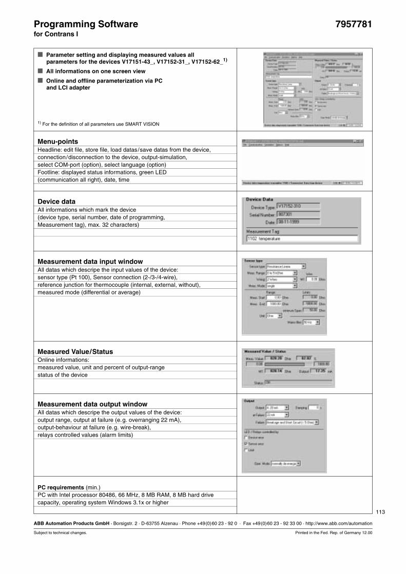
113
ABB Automation Products GmbH · Borsigstr. 2 · D-63755 Alzenau · Phone +49(0)60 23 - 92 0 · Fax +49(0)60 23 - 92 33 00 · http://www.abb.com/automation
Subject to technical changes. Printed in the Fed. Rep. of Germany 12.00
Programming Software 7957781for Contrans I
Parameter setting and displaying measured values allparameters for the devices V17151-43_, V17152-31_, V17152-62_1)
All informations on one screen view
Online and offline parameterization via PCand LCI adapter
1) For the definition of all parameters use SMART VISION
Menu-pointsHeadline: edit file, store file, load datas/save datas from the device,connection/disconnection to the device, output-simulation,select COM-port (option), select language (option)Footline: displayed status informations, green LED (communication all right), date, time
Device dataAll informations which mark the device(device type, serial number, date of programming,Measurement tag), max. 32 characters)
Measurement data input windowAll datas which descripe the input values of the device:sensor type (Pt 100), Sensor connection (2-/3-/4-wire),reference junction for thermocouple (internal, external, without),measured mode (differential or average)
Measured Value/StatusOnline informations:measured value, unit and percent of output-rangestatus of the device
Measurement data output windowAll datas which descripe the output values of the device:output range, output at failure (e.g. overranging 22 mA),output-behaviour at failure (e.g. wire-break),relays controlled values (alarm limits)
PC requirements (min.)PC with Intel processor 80486, 66 MHz, 8 MB RAM, 8 MB hard drivecapacity, operating system Windows 3.1x or higher
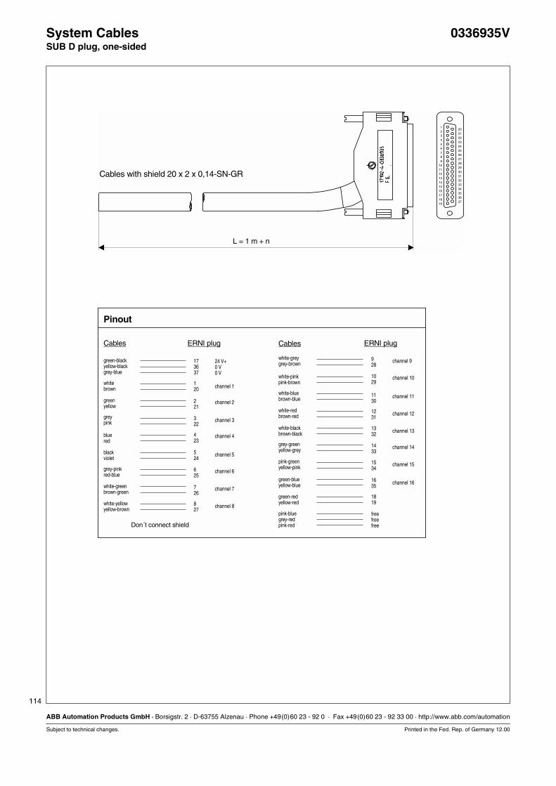
114
ABB Automation Products GmbH · Borsigstr. 2 · D-63755 Alzenau · Phone +49(0)60 23 - 92 0 · Fax +49(0)60 23 - 92 33 00 · http://www.abb.com/automation
Subject to technical changes. Printed in the Fed. Rep. of Germany 12.00
System Cables 0336935VSUB D plug, one-sided
123456789
10111213141516171819
202122232425262728293031323334353637
L = 1 m + n
Cables with shield 20 x 2 x 0,14-SN-GR
173637
120
221
322
423
524
625
726
827
24 V+0 V0 V
928
1029
1130
1231
1332
1433
1534
1635
1819
Don´t connect shield
Cables
Pinout
CablesERNI plug ERNI plug
green-blackyellow-blackgrey-blue
whitebrown
greenyellow
greypink
bluered
blackviolet
grey-pinkred-blue
white-greenbrown-green
white-yellowyellow-brown
channel 1
channel 2
channel 3
channel 4
channel 5
channel 6
channel 7
channel 8
white-greygrey-brown
white-pinkpink-brown
white-bluebrown-blue
white-redbrown-red
white-blackbrown-black
grey-greenyellow-grey
pink-greenyellow-pink
green-blueyellow-blue
green-redyellow-red
pink-bluegrey-redpink-red
freefreefree
channel 9
channel 10
channel 11
channel 12
channel 13
channel 14
channel 15
channel 16
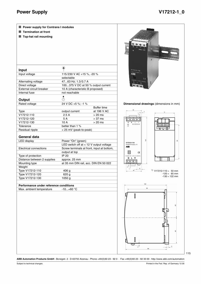
115
ABB Automation Products GmbH · Borsigstr. 2 · D-63755 Alzenau · Phone +49(0)60 23 - 92 0 · Fax +49(0)60 23 - 92 33 00 · http://www.abb.com/automation
Subject to technical changes. Printed in the Fed. Rep. of Germany 12.00
Power Supply V17212-1_0
Power supply for Contrans I modules
Termination at front
Top-hat rail mounting
InputInput voltage 115/230 V AC +15 %, -20 %
selectableAlternating voltage 47...63 Hz; 1.3/0.7 ADirect voltage 100...375 V DC at 50 % output currentExternal circuit breaker 10 A (characteristic B proposed)Internal fuse not reachable
OutputRated voltage 24 V DC +5 %; -1 % Dimensional drawings (dimensions in mm)
Buffer timeType output current at 196 V ACV17212-110 2.5 A > 20 msV17212-120 5 A > 37 msV17212-130 10 A > 20 msTolerance better than 1 %Residual ripple < 25 mV (peak-to-peak)
General dataLED display Power “On“ (green)
LED switch off at < 12 V output voltageElectrical connections Screw terminals at front, input at bottom,
output at topType of protection IP 20Distance between 2 supplies approx. 25 mmMounting type at 35 mm DIN rail, acc. DIN EN 50 022WeightType V17212-110 406 gType V17212-120 620 gType V17212-130 1050 g
Performance under reference conditionsMax. ambient temperature -10...+60 °C
1)
N L
84
102
94
6262
99
54
1) V17212-110 = 50 mm1) V17212-120 = 65 mm1) V17212-130 = 122 mm

12.00 117
Safety Instructions
Encoding
Mounting and Installation Instructions
118 12.00
Correct and safe operation of Contrans I calls for appropriatetransportation and storage, expert installation and commission-ing as well as correct operation and meticulous maintenance.
Only those persons conversant with the installation, commis-sioning, operation and maintenance of similar apparatuses andwho posses the necessary qualifications are allowed to work onContrans I.
Contrans I has been designed and tested in conform withEN 61010-1 or DIN VDE 0411, Part 1 “Safety requirements forelectrical process control units, instrumentation and laboratorydevices“, overvoltage category II, pollution class 2 and has beensupplied in a safe condition.
In order to retain this condition and to ensure safe operation, thefollowing safety instructions must be observed. Otherwise,persons can be endangered and the Contrans I componentsthemselves as well as other equipment and facilities can bedemaged.
Before plugging the module into the socket, care must betaken to ensure that the socket circuitry agrees with that ofthe connecting diagram. For voltages > 50 V AC or 120 V DCthe terminals must be market with the rated voltage or thesocket must be coded. The coding or marking must corre-spond th the “Mounting and Installation Instructions“.
For voltages higher than 50 V AC/120 V DC, the insulationlengths of terminal wires must be between 5...6 mm. If moreflexible lines are used, the end ferrules used should havethese lengths.
Before switching on devices of the protection class III, it mustbe ascertained that the power source has a functional extra-low voltage with an electrical isolation corresponding to theexisting provisions.
When opening covers or removing parts, except when this ismanually possible, live parts may be exposed.
The apparatus shall be disconnected from all voltagesources before it is opened for any operations. Operationson the opened apparatus under voltage must only beperformed by an expert, who is aware of the hazardinvolved.
Whenever it is likely that the protection has been impaired,the apparatus shall be made inoperative and be securedagainst any unintended operation.
Apart from the technical documentation in this catalog, thefollowing must also be observed:
The safety regulations pertaining to the installation andoperation of electrical systems,
the directives and guidelines on explosion protection.
If the information supplied in this catalog should prove to beinsufficient, the ABB service department will be pleased toprovide you with more information.
Safety Instructions
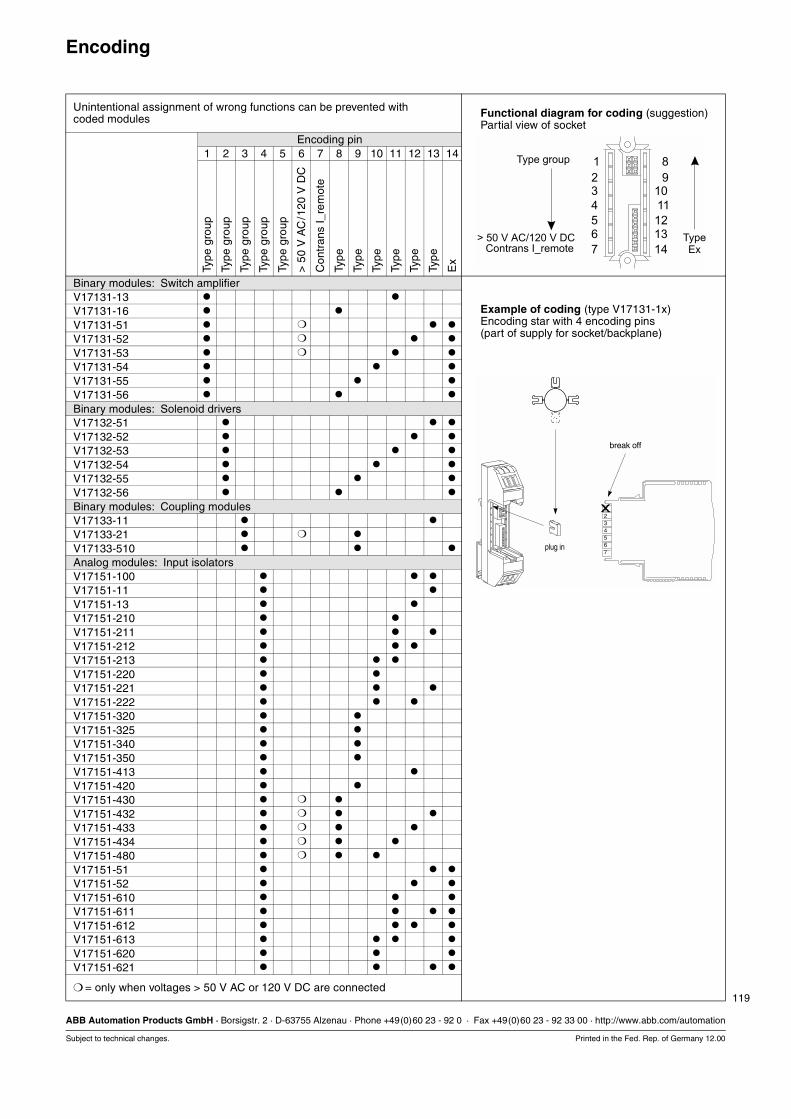
119
ABB Automation Products GmbH · Borsigstr. 2 · D-63755 Alzenau · Phone +49(0)60 23 - 92 0 · Fax +49(0)60 23 - 92 33 00 · http://www.abb.com/automation
Subject to technical changes. Printed in the Fed. Rep. of Germany 12.00
Encoding
Unintentional assignment of wrong functions can be prevented withcoded modules Functional diagram for coding (suggestion)
Partial view of socketEncoding pin
1 2 3 4 5 6 7 8 9 10 11 12 13 14
Type
gro
up
Type
gro
up
Type
gro
up
Type
gro
up
Type
gro
up
> 5
0 V
AC
/120
V D
C
Con
tran
s I_
rem
ote
Type
Type
Type
Type
Type
Type
Ex
Binary modules: Switch amplifierV17131-13
Example of coding (type V17131-1x)Encoding star with 4 encoding pins(part of supply for socket/backplane)
V17131-16
V17131-51
V17131-52
V17131-53
V17131-54
V17131-55
V17131-56
Binary modules: Solenoid driversV17132-51
V17132-52
V17132-53
V17132-54
V17132-55
V17132-56
Binary modules: Coupling modulesV17133-11
V17133-21
V17133-510
Analog modules: Input isolatorsV17151-100
V17151-11
V17151-13
V17151-210
V17151-211
V17151-212
V17151-213
V17151-220
V17151-221
V17151-222
V17151-320
V17151-325
V17151-340
V17151-350
V17151-413
V17151-420
V17151-430
V17151-432
V17151-433
V17151-434
V17151-480
V17151-51
V17151-52
V17151-610
V17151-611
V17151-612
V17151-613
V17151-620
V17151-621
= only when voltages > 50 V AC or 120 V DC are connected
1234567
x
break off
plug in
1
3
4
2
6
7
12
11
109
8
13
14
5
Contrans I_remote
Type group
TypeEx
> 50 V AC/120 V DC
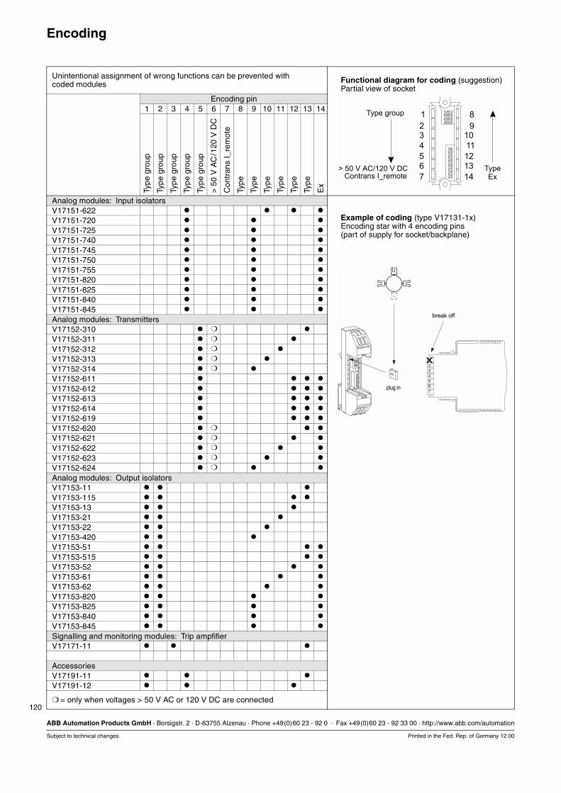
120
ABB Automation Products GmbH · Borsigstr. 2 · D-63755 Alzenau · Phone +49(0)60 23 - 92 0 · Fax +49(0)60 23 - 92 33 00 · http://www.abb.com/automation
Subject to technical changes. Printed in the Fed. Rep. of Germany 12.00
Encoding
Unintentional assignment of wrong functions can be prevented withcoded modules Functional diagram for coding (suggestion)
Partial view of socketEncoding pin
1 2 3 4 5 6 7 8 9 10 11 12 13 14
Type
gro
up
Type
gro
up
Type
gro
up
Type
gro
up
Type
gro
up
> 5
0 V
AC
/120
V D
C
Con
tran
s I_
rem
ote
Type
Type
Type
Type
Type
Type
Ex
Analog modules: Input isolators
Example of coding (type V17131-1x)Encoding star with 4 encoding pins(part of supply for socket/backplane)
V17151-622
V17151-720
V17151-725
V17151-740
V17151-745
V17151-750
V17151-755
V17151-820
V17151-825
V17151-840
V17151-845
Analog modules: TransmittersV17152-310
V17152-311
V17152-312
V17152-313
V17152-314
V17152-611
V17152-612
V17152-613
V17152-614
V17152-619
V17152-620
V17152-621
V17152-622
V17152-623
V17152-624
Analog modules: Output isolatorsV17153-11
V17153-115
V17153-13
V17153-21
V17153-22
V17153-420
V17153-51
V17153-515
V17153-52
V17153-61
V17153-62
V17153-820
V17153-825
V17153-840
V17153-845
Signalling and monitoring modules: Trip ampfifierV17171-11
AccessoriesV17191-11
V17191-12
= only when voltages > 50 V AC or 120 V DC are connected
1234567
x
break off
plug in
1
3
4
2
6
7
12
11
109
8
13
14
5
Contrans I_remote
Type group
TypeEx
> 50 V AC/120 V DC

ABB Automation Products GmbHBorsigstr. 2, D-63755 AlzenauPhone +49 (0) 6023 92 0, Fax +49 (0) 6023 92 3430www.abb.com/automation 04/17.1 EN 11.00