instrument flying - pathfinder aviation
TRANSCRIPT
Instrument FlyingThese instrument lessons will be dictated by conditions on the day. It is expected that the student be sent solo to practise these manoeuvres in the training area on a regular basis between dual lessons, however they will need a safety pilot for any simulated instrument flight. Please refer to your CFI.


ContentsCompass Use
Introduction
Limited Panel
Unusual Attitudes
Night Flying


Instrument FlyIng
ObjectiveTo turn accurately onto and maintain compass headings, compensating for known errors in the magnetic compass.
Compass useThe magnetic compass is the primary navigation aid for most light aeroplanes.
It is the only instrument in most light aeroplanes that indicates the correct heading. The directional indicator (DI) or directional gyro (DG) is simply gyro-stabilised and can be set to any heading. To be of any value it must be manually aligned with the magnetic compass on a regular basis.
In using the magnetic compass for navigation purposes there are more considerations than just the turning errors.
The magnetic compass displays several errors in its use, most of which the DI eliminates. If for any reason the DI becomes unusable, the pilot will need to be able to turn onto and maintain a compass heading.
The cause of compass errors is not as important as how to compensate for those errors in flight. A basic understanding of the causes of compass errors is all that is required.
ConsiderationsVariationThe earth has a geographical (True) North Pole and a geographical (True) South Pole.
A magnetic field exists around the earth, produced by the equivalent of a very large bar magnet within the earth. This results in a Magnetic North Pole and a Magnetic South Pole.
Figure 1
The magnetic poles are not in the same places as the true poles; however, currently they are close, enabling us to use magnets to navigate around the world.

2 Instrument Flying: Compass Use
The angular difference between true north and magnetic north at any point on the earth is called variation. This difference is more relevant when navigating as maps are drawn with reference to true north, and the aircraft is navigated by reference to magnetic north. This will be covered during future navigation lessons.
DeviationWhen the bar magnet or magnetic compass is acted upon by a magnetic field other than the earth’s, the magnet deviates. Most metal objects or electrical fields produce a magnetic field that will cause the compass to read incorrectly. This effect is known as deviation. It is compensated for by the ‘compass swing’ procedure, which minimises the errors and records the residual errors.
DipAt the magnetic equator, the earth’s magnetic field lies parallel with the earth’s surface, and a bar magnet would also lie parallel. As the poles are approached, the lines of flux dip down toward the earth’s surface, and so does a bar magnet.
Suspending the compass card from a pivot point above the magnet almost eliminates dip.
The pivot arrangement is unstable, so the compass card and magnets are immersed in a fluid that damps out oscillations, which also provides lubrication.
Figure 2
Acceleration ErrorsThe compass always sits at a slight angle to the earth because the magnet is suspended below a pivot point. The centre of gravity of the magnet will not lie directly beneath the pivot point, and when the aeroplane accelerates or decelerates the centre of gravity lags behind and rotates the compass card.
This does not happen when heading north or south, and is at a maximum when heading east or west.
In practise, the compass will indicate an apparent turn toward the South when Accelerating and an apparent turn toward the North when Decelerating. The mnemonic SAND is used to remember these effects.
Although power changes, in aeroplanes with sufficient power, may produce acceleration or deceleration errors, these errors are most noticeable during attitude changes.
Turning ErrorsIn a balanced turn the bar magnet stays aligned with the aeroplane and therefore increases its angle to the horizon.
To compensate for this, when turning onto northerly headings the pilot must continue the turn past the indicated heading, and when turning onto southerly headings, stop the turn before the desired compass heading.
The mnemonic ONUS is used to remember this;
• Overturn the required heading when turning onto Northerly headings and
• Underturn the required heading when turning onto Southerly headings.
The compass turn is carried out at Rate One – this is a turn of 360 degrees in two minutes.
While turning at Rate One, the error between the desired heading and the indicated heading on 000 and 180 is approximately 30 degrees. For this correction to work the turn must be Rate One, balanced, level and without pitch changes.
Instrument Flying: Compass Use 3
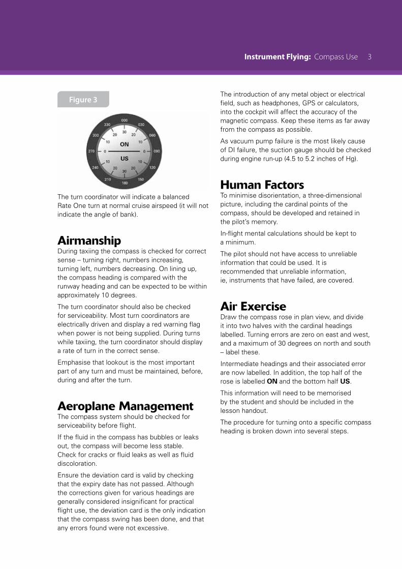
Figure 3
The turn coordinator will indicate a balanced Rate One turn at normal cruise airspeed (it will not indicate the angle of bank).
AirmanshipDuring taxiing the compass is checked for correct sense – turning right, numbers increasing, turning left, numbers decreasing. On lining up, the compass heading is compared with the runway heading and can be expected to be within approximately 10 degrees.
The turn coordinator should also be checked for serviceability. Most turn coordinators are electrically driven and display a red warning flag when power is not being supplied. During turns while taxiing, the turn coordinator should display a rate of turn in the correct sense.
Emphasise that lookout is the most important part of any turn and must be maintained, before, during and after the turn.
Aeroplane ManagementThe compass system should be checked for serviceability before flight.
If the fluid in the compass has bubbles or leaks out, the compass will become less stable. Check for cracks or fluid leaks as well as fluid discoloration.
Ensure the deviation card is valid by checking that the expiry date has not passed. Although the corrections given for various headings are generally considered insignificant for practical flight use, the deviation card is the only indication that the compass swing has been done, and that any errors found were not excessive.
The introduction of any metal object or electrical field, such as headphones, GPS or calculators, into the cockpit will affect the accuracy of the magnetic compass. Keep these items as far away from the compass as possible.
As vacuum pump failure is the most likely cause of DI failure, the suction gauge should be checked during engine run-up (4.5 to 5.2 inches of Hg).
Human FactorsTo minimise disorientation, a three-dimensional picture, including the cardinal points of the compass, should be developed and retained in the pilot’s memory.
In-flight mental calculations should be kept to a minimum.
The pilot should not have access to unreliable information that could be used. It is recommended that unreliable information, ie, instruments that have failed, are covered.
Air ExerciseDraw the compass rose in plan view, and divide it into two halves with the cardinal headings labelled. Turning errors are zero on east and west, and a maximum of 30 degrees on north and south – label these.
Intermediate headings and their associated error are now labelled. In addition, the top half of the rose is labelled ON and the bottom half US.
This information will need to be memorised by the student and should be included in the lesson handout.
The procedure for turning onto a specific compass heading is broken down into several steps.
4 Instrument Flying: Compass Use
Making the Turn
Which Way to Turn?The turn is always made in the shortest direction; for example, a turn from east to north requires a turn to the left.
Given the presentation of the compass rose, this is quite a simple deduction. However, the aeroplane’s magnetic compass does not present the information in this format. Therefore, some method of deciding the shortest arc to turn through must be provided to the student.
It is assumed that the DI has failed or is unreliable so should be removed from the pilot’s scan. As the simple plan view of the compass rose is easy to interpret and is what the student has memorised, some other instrument, preferably orientated with north always at the top, is substituted for the DI.
There are several methods available.
Firstly – and best – the back of the cover used to hide the DI could have a drawing printed on it that shows the error or correction associated with each cardinal and intermediate heading.
Secondly, if the aeroplane is fitted with an ADF or VOR, the remote indicators associated with these (ADF card or CDI) may be used as a reference.
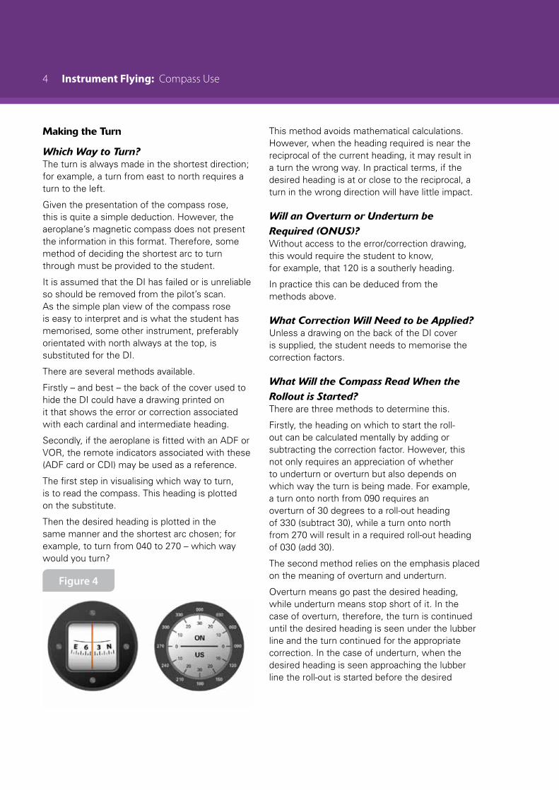
The first step in visualising which way to turn, is to read the compass. This heading is plotted on the substitute.
Then the desired heading is plotted in the same manner and the shortest arc chosen; for example, to turn from 040 to 270 – which way would you turn?
Figure 4
This method avoids mathematical calculations. However, when the heading required is near the reciprocal of the current heading, it may result in a turn the wrong way. In practical terms, if the desired heading is at or close to the reciprocal, a turn in the wrong direction will have little impact.
Will an Overturn or Underturn be Required (ONUS)?Without access to the error/correction drawing, this would require the student to know, for example, that 120 is a southerly heading.
In practice this can be deduced from the methods above.
What Correction Will Need to be Applied?Unless a drawing on the back of the DI cover is supplied, the student needs to memorise the correction factors.
What Will the Compass Read When the Rollout is Started?There are three methods to determine this.
Firstly, the heading on which to start the roll-out can be calculated mentally by adding or subtracting the correction factor. However, this not only requires an appreciation of whether to underturn or overturn but also depends on which way the turn is being made. For example, a turn onto north from 090 requires an overturn of 30 degrees to a roll-out heading of 330 (subtract 30), while a turn onto north from 270 will result in a required roll-out heading of 030 (add 30).
The second method relies on the emphasis placed on the meaning of overturn and underturn.
Overturn means go past the desired heading, while underturn means stop short of it. In the case of overturn, therefore, the turn is continued until the desired heading is seen under the lubber line and the turn continued for the appropriate correction. In the case of underturn, when the desired heading is seen approaching the lubber line the roll-out is started before the desired
Instrument Flying: Compass Use 5
heading is reached by the appropriate correction.
A third method, more appropriate to CPL training than basic training, of estimating when to roll out relies on timing. Since a Rate One turn results in a turn of 360 degrees in two minutes, the rate of turn is calculated as three degrees per second. Knowing the arc to be turned through, the amount of time required at Rate One can be calculated and the turn timed using the clock.
When the calculated heading to roll out on is seen under the lubber line, roll out smoothly. Anticipation of the heading by 3 degrees, given the roll out takes about one second, should allow for an accurate compass turn. Immediately choose a reference point on the horizon and fly on the reference point, wings level, and balanced. Give the compass time to settle, do not chase the heading.
When reading the compass, ensure that the wings are level and that the aeroplane is in steady balanced flight, as these are the only conditions under which the compass will read accurately.
Making the CorrectionOften the required heading will not have been achieved exactly, so minor corrections will need to be made, using the 3 degrees per second Rate One turn principle.
Which Way to Turn?Because of the way heading information is presented by the magnetic compass it is vital to read the compass. The most common errors involve simply turning toward the desired heading or matching the position of the heading indicator on the DI with the lubber line’s position.
One method is to reverse the sense. For example, if the required heading is left of the lubber line, turn right. This sounds simple but many students find this method confusing.
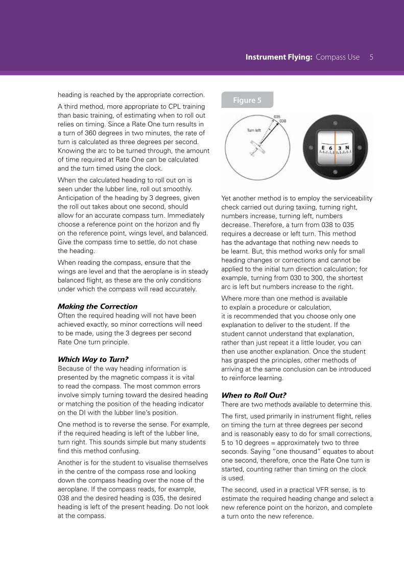
Another is for the student to visualise themselves in the centre of the compass rose and looking down the compass heading over the nose of the aeroplane. If the compass reads, for example, 038 and the desired heading is 035, the desired heading is left of the present heading. Do not look at the compass.
Figure 5
Yet another method is to employ the serviceability check carried out during taxiing, turning right, numbers increase, turning left, numbers decrease. Therefore, a turn from 038 to 035 requires a decrease or left turn. This method has the advantage that nothing new needs to be learnt. But, this method works only for small heading changes or corrections and cannot be applied to the initial turn direction calculation; for example, turning from 030 to 300, the shortest arc is left but numbers increase to the right.
Where more than one method is available to explain a procedure or calculation, it is recommended that you choose only one explanation to deliver to the student. If the student cannot understand that explanation, rather than just repeat it a little louder, you can then use another explanation. Once the student has grasped the principles, other methods of arriving at the same conclusion can be introduced to reinforce learning.
When to Roll Out?There are two methods available to determine this.
The first, used primarily in instrument flight, relies on timing the turn at three degrees per second and is reasonably easy to do for small corrections, 5 to 10 degrees = approximately two to three seconds. Saying “one thousand” equates to about one second, therefore, once the Rate One turn is started, counting rather than timing on the clock is used.
The second, used in a practical VFR sense, is to estimate the required heading change and select a new reference point on the horizon, and complete a turn onto the new reference.
6 Instrument Flying: Compass Use
In either case, roll out smoothly, maintain balanced level flight on the reference point, and allow the compass time to settle.
Airborne SequenceOn the GroundDuring the preflight inspection pay particular attention to the serviceability checks of the compass and the validity of the deviation card.
Look at the compass heading before turning the master switch on and the watch the effect of starting the engine.
During the taxiing instrument checks, note that the turn coordinator gives a rate of turn, not the angle of bank, and that the DI can be set to read any heading desired, regardless of the aeroplane’s actual heading.
The ExerciseThe airborne sequence starts with a demonstration of acceleration/deceleration errors. Maintaining a heading of 090 or 270 by reference to the DI or reference point, accelerate the aeroplane by smoothly pitching the nose down; note the apparent turn toward the south. This exercise is repeated to demonstrate deceleration effects by smoothly pitching the nose up; note the apparent turn toward the north.
Rapid movements of the throttle to produce this effect (negating all previous engine handling training) is neither required or relevant.
When this exercise is repeated on headings of 000 or 180 no apparent turn will occur, although the compass may be seen to dip. Ensure the aeroplane is kept straight by reference to the DI or reference point.
The demonstration of acceleration errors is concluded with a reminder, that when accelerating, decelerating or pitching, keep straight on the reference point. In addition, to compensate for turning errors accurately, it will be necessary to avoid pitch changes during the Rate One turn.
Turning errors are demonstrated by completing a 360 degree Rate One turn and noting the difference between the compass heading and the DI on cardinal and intermediate headings. Point out that these errors or corrections are only true in a level, balanced, Rate One turn. Start on a compass heading of 090 or 270 (with the DI aligned) and have the student read out the compass heading when you read out a DI heading. In a turn to the right you read out 030 (DI), the student should read out about 010 compass, a 20-degree difference.
Once the errors have been observed, a DI failure is simulated. Using the recommended steps, compass turns onto cardinal headings are practised.
Beware of lookout degradation during calculations.
Commonly, when the aeroplane is rolled wings level, there is a tendency by the student to fixate on the compass rather than maintain level flight on a distant reference point. This tendency can be overcome by covering the compass with your hand just as the student starts the roll-out and insisting that they choose and fly a reference point. Allow the compass adequate time to settle, ensure the aeroplane is in balanced flight, and then remove your hand to read the compass.
Depending on which method is used for minor corrections, cover the compass again and calculate which way to turn. Calculate the time required or choose a new reference, turn and regain balanced level flight. Allow the compass to settle and remove your hand to read the compass.
When the compass reads the correct heading, emphasise the reference point to maintain heading. Do not allow the student to fixate on the compass – instruments are used to confirm performance, not set it.
After FlightThe student will need to practise these solo.
Instrument FlyIng
ObjectivesTo experience the sensory illusions which occur when deprived of visual references.
To maintain straight and level flight by sole reference to the aeroplane’s instruments.
To climb, descend and turn by sole reference to the aeroplane’s instruments.
IntroductionFlight in cloud can be dangerous because when we are deprived of visual references, the body’s other senses may provide conflicting information to the brain. Without the benefit of visual references to resolve these conflicts, loss of aeroplane control can occur very quickly, usually within a minute.
However, instrument flying has a practical application to visual flying when the normal cues are missing or misleading; for example, low flying, mountain flying, night flying, or flying over water with a poor horizon.
Instrument flight is challenging because of the need to interpret and anticipate the instrument readings while recognising or ignoring the conflicting messages sent to the brain by our earthbound orientated senses.
Inadvertent flight into cloud can be avoided by maintaining a high level of situational awareness. However, a five-hour course of instrument flying is included in the requirements for PPL issue, to give the pilot and passengers some chance of survival should the event occur.
ConsiderationsDescribe the method of simulation that you will use, for example, hood or glasses.
Discuss the direct and indirect information that each of the flight and engine instruments give, as well as their power source.
The formula Power + Attitude = Performance remains unchanged for instrument flight. There are two types of instruments; control instruments and performance instruments.
Control Instruments
Attitude Indicator or Artificial HorizonThe Attitude Indicator (AI) or Artificial Horizon (AH) is the master instrument, because it presents pitch and bank attitude information directly (in miniature) against an artificial horizon.
Miniaturisation of the outside world means that small movements indicated on the attitude indicator represent quite noticeable changes in pitch and bank. Therefore, it is common to speak of pitch attitude changes in relation to the width of the wing bars representing the aeroplane within the AI. For example, the straight and level attitude is half a wing bar width above the horizon.
2 Instrument Flying: Introduction
Indirectly, the attitude indicator is a guide to airspeed (nose low – high or increasing airspeed, nose high – low or decreasing airspeed).
The attitude indicator is most commonly driven by an engine-driven vacuum pump.
TachometerThe tachometer directly indicates the engine rpm and indirectly the engine power output. In addition, rpm may indirectly indicate pitch attitude (rpm increasing – nose low, rpm decreasing – nose high).
The tachometer is commonly driven from the engine by a mechanical cable.
Performance Instruments
Airspeed IndicatorThis gives the aeroplane’s speed directly and, indirectly, pitch attitude (airspeed increasing – nose low, airspeed decreasing – nose high). Its source of information is the pitot-static system.
AltimeterThe altimeter directly indicates the height of the aeroplane above a datum, usually sea level. Indirectly, it indicates pitch attitude (altitude decreasing – nose low, altitude increasing – nose high). Its source of information is the static system.
Heading Indicator The heading indicator is known as the Directional Indicator (DI), Directional Gyro (DG), or Horizontal Situation Indicator (HSI). The DI directly indicates the aeroplane’s heading when aligned with the magnetic compass. Indirectly, it can indicate bank. Heading indicators are commonly driven by the engine-driven vacuum pump.
Turn CoordinatorThe Turn Coordinator (TC), or Turn Indicator, directly indicates the rate of change of direction. Indirectly, it can indicate limited angles of bank (provided balance is maintained), commonly up to about 35 degrees. Any further increase in bank angle will not be indicated by the turn coordinator. Turn coordinators are normally electrically driven.
Balance IndicatorThis Balance Indicator is commonly incorporated within the turn coordinator and directly indicates balance. Indirectly, it indicates yaw if the wings are level, or bank. Its power source is gravity, or the resultant of in-flight accelerations (CPF, CFF).
Vertical Speed IndicatorThe Vertical Speed Indicator (VSI) directly indicates the rate of change of altitude. Indirectly, it indicates pitch attitude, and it is most useful when used as a trend indicator, as it will indicate a tendency to change altitude long before the altimeter registers any change. Its information source is the static system.
Instrument LayoutThe four instruments, Attitude Indicator, Airspeed Indicator, Altimeter, and Heading Indicator, are arranged on the instrument panel in a Basic T-shape.
The addition of the Turn Coordinator/Balance Indicator, and the Vertical Speed Indicator make up the full instrument flying panel.
While not part of the six instruments referred to the rpm gauge is incorporated into scan techniques as appropriate.
Instrument LagAll instruments suffer from lag, some to a greater extent than others. All instruments, other than the VSI, can be considered to be responsive enough for light aeroplane use. The VSI, however, suffers from significant lag, and must be cross-referenced with other instruments to check its indications.
AirmanshipThe importance of checking instruments while taxiing, and in-flight SADIE checks are revised.
During visual flight training the requirement to counteract inertia (change – check – hold – adjust – trim) will have become automatic as a result of cues detected by peripheral vision. These cues will no longer be available and the necessity to consciously counteract inertia through this process when changing attitude will need to be emphasised during early instrument lessons.
Instrument Flying: Introduction 3
The student should be prompting the lookout, by calling “clear left?” if a left turn is to be conducted and should receive a “clear left” response from the instructor.
Aeroplane ManagementThe aeroplane’s vacuum and pitot-static systems should be described.
The method of setting the attitude indicator’s aeroplane symbol before flight, and the desirability of not altering it in flight, are explained.
Human FactorsHumans use three sensing systems to gather and transmit information to the brain in order to remain orientated. These are the balance organs within the vestibular system of the inner ear, the muscular pressure sensors of the nervous system, and vision – the most powerful system of the three.
The balance organs of the vestibular system sense angular acceleration or change of direction in three different planes by the detection of fluid movement in the semicircular canals. In addition, the otolith organ senses linear acceleration as well as head or body tilt, through the movement of a jelly-like mass over sensitive hairs.
This system is limited by the inability to detect change when the direction or the angular acceleration is constant or very slow. It can also misrepresent acceleration as a nose pitch up, because of the effect of inertia.
The muscular pressure sensors of the nervous system are affected by gravity and allow us to detect, for example, whether we are standing or sitting when our eyes are closed.
Crucially, this system cannot differentiate between the various causes of increased G, for example, as the result of pulling out of a dive or of entering a steep turn.
The visual system is the most powerful of the orientation systems and normally resolves any ambiguous or conflicting information received by the brain, for example, this is a steep turn not a pull-out of a dive.
In instrument flight conditions the visual references used to resolve ambiguous or conflicting orientation information are not available. Until considerable practise has been carried out to replace the normal visual cues with instrument readings, orientation conflicts may occur, causing various illusions, for example, the leans.
Because the limitations of the human orientation system are considerable, and instrument failure is rare, trust the instruments.
Air ExerciseThe air exercise starts with a demonstration of the limitations of the vestibular and muscular systems.
Selective Radial ScanSelective radial scanning recognises that the attitude indicator is the master instrument and therefore employs an instrument scanning pattern that radiates out from, and always returns to, the attitude indicator.
The relative importance of the performance instruments varies – and therefore the scan rate varies – with the manoeuvre being executed. Describe this in relation to maintaining straight and level as well as achieving straight and level from the climb and descent.
Airborne SequenceThe ExerciseIt is important to demonstrate the limitations of the body’s physiological orientation systems carefully. The instructions below should be followed exactly so that the student experiences the false sensations of turning and pitching. An unconvincing demonstration may lead the student to believe they are immune to false indications. There are many demonstrations that show the susceptibility of the human senses to disorientation; it should only be necessary to show a few of them.

4 Instrument Flying: Introduction
The False Sensation of TurningIn straight and level flight, ask the student to close their eyes and lower their head, remind them to resist any temptation to look out, if they do they will not feel what is normally sensed during instrument flight.
Lower the right wing very gently and then positively roll the wings level while raising the nose attitude without changing power. At this stage ask the student what attitude the aeroplane is in. Their balance and postural sensations will normally lead them to conclude that the aeroplane has entered a turn to the left.
The False Sensation of ClimbingIn straight and level flight, ask the student to close their eyes and lower their head. Enter a medium turn to the left using a positive entry, then very gently change to a turn to the right while applying consistent backpressure to the control column. Ask the student to tell you what attitude they think the aeroplane is in. The sensation they have felt will be that the aeroplane is in a climbing left turn.
Once the student has seen that the sensation received from the senses of balance and posture can be misleading, they will have a better appreciation of the need to be able to fly by instrument reference before attempting to enter cloud or any other condition where outside visual references are minimal or completely absent.
It is not necessary to handle the aeroplane violently or adopt extremes of attitude to achieve the effects of disorientation.
During transitions from the climb or descent to straight and level it will be necessary to slow the students actions down to consciously follow the change – check – hold – adjust – trim sequence.
Student PractiseThe student should have observed the instruments on previous VFR flights to verify that small movements on the AI result in noticeable changes in pitch and bank.
Now have the student put on the hood or glasses, get comfortable and ensure they cannot see out. Then they should practise the selective radial scan, first in straight and level, and then moving on to climbs, descents and turns, emphasising the change – check – hold – adjust – trim sequence.
On the GroundThe handout for this lesson should include the limitations of the human balance system, as well as a range of articles on incidents and accidents resulting from attempting continued VFR flight into deteriorating weather.

Instrument FlyIng
limited PanelWhen any one or more of the basic six flight instruments fails, or is unserviceable, the instrument panel is limited.
Failure of the master instrument, the Attitude Indicator (AI), is the most serious and, therefore, the most commonly simulated. However, failure of the other instruments does occur and it is important to recognise the failure early.
Limited-panel instrument flight at the PPL level requires only the ability to fly straight and level and carry out level Rate One turns onto compass headings (sufficient to reverse course and fly out of cloud). Additional briefings will be required to
adequately cover the requirements of limited-panel instrument flight for CPL students.
This exercise simulates the failure of one or more flight instruments, before or after inadvertently entering cloud. In this situation indirect readings of the other flight instruments are used to fill in the gaps as a result of losing the direct information from the failed instruments.
Limited-panel instrument flight still employs the selective radial scan technique, which recognises the changing importance of various instruments with the phase of flight.
ObjectivesTo maintain straight and level flight by sole reference to a limited flight instrument panel.
To carry out Rate One level turns onto compass headings.
ConsiderationsVarious power or information source failures, and their effects on the flight instruments, are discussed, from the least serious to the most serious.
Although the tachometer is not a flight instrument, its possible failure should be briefly discussed. Rpm can be estimated from sound and, since only the gauge is unserviceable, power is still available to be used as required.
Turn Coordinator (or Turn Indicator)Turn coordinators are normally electrically driven. If power is not being supplied to the turn coordinator, a warning flag is displayed. Its failure would mean that the rate of turn would have to be estimated using angle of bank (about 15 degrees for Rate One, up to 100 knots). The balance indicator is unaffected.
The turn coordinator is checked for serviceability during taxiing and the electrical system during SADIE checks.
2 Instrument Flying: Limited Panel
Vertical Speed Indicator and AltimeterBoth VSI and altimeter rely directly on outside air pressure sensed at the static vent. If the static vent becomes blocked, neither the VSI nor the altimeter will indicate correctly.
Failure of the VSI and altimeter would require use of the control instruments (AI and tachometer) to achieve the desired performance. For example, an attitude for 70 knots plus power setting of about 1500 rpm, equals a rate of descent of about 500 feet per minute.
The static vent is inspected for blockages during the preflight inspection.
Airspeed IndicatorThe airspeed indicator’s source of power is a combination of the static and pitot system. If the static vent is blocked, airspeed indications will decrease in the climb and increase in the descent. If the pitot system is blocked (most commonly by ice), airspeed indications will decrease in the descent and increase in the climb or, depending on the type of pitot/static system, airspeed indications may simply reduce to zero in level flight.
Failure of the ASI requires use of the control instruments (AI and tachometer) to achieve the desired performance.
The pitot tube is inspected for blockages during the preflight inspection.
Heading IndicatorHeading indicators are gyro-stabilised and are commonly driven by the engine-driven vacuum pump. If the vacuum pump fails the gyro will gradually run down, losing rigidity, and the DI will become unusable.
Failure of the DI requires direct use of the magnetic compass for heading information.
The DI and vacuum system are checked for serviceability before flight during the taxi and the engine run-up, and in-flight with SADIE checks.
Remember that the DI will need to be regularly aligned with the compass, as precession will cause it to indicate the wrong heading.
Attitude IndicatorThe Attitude Indicator is most commonly driven by an engine-driven vacuum pump.
Failure of the AI will require use of the indirect information available from the performance instruments to establish the aeroplane’s attitude.
AI serviceability is checked during taxiing and in flight with SADIE checks.
AirmanshipRevise the importance of checking instruments while taxiing and in-flight SADIE checks.
Aeroplane ManagementRevise knowledge of the aeroplane’s systems in the event of a malfunction.
The turn coordinator and electrical system are protected by circuit breakers (CB). Electrical failure may affect other instruments, for example, fuel gauges.
The static system is commonly backed up by an alternate static source, the location and operation of this should be described.
The pitot head is commonly heated to prevent ice build up.
The serviceability of the vacuum system is confirmed by regular reference to the vacuum gauge.
Using the SADIE checks will help to ensure the DI is regularly aligned with the compass.
Human FactorsDeveloping a systematic instrument scan to maintain situational awareness is critical.
Because the limitations of the human orientation system are considerable, and instrument failure is rare, trust the instruments.
The pilot should not have access to unreliable information that could be used in any way. It is recommended that unreliable information is covered.
Instrument Flying: Limited Panel 3
Air ExerciseFor this exercise a failure of the vacuum system is simulated – AI and DI unserviceable – and the information available from each instrument to maintain control in each plane is revised.
PitchDetermined from airspeed, altimeter, vertical speed indicator and rpm (noise).
BankDetermined from turn coordinator when balanced (ball), and compass.
YawDetermined from balance (ball).
The selective radial scan (SRS) technique is described in relation to maintaining straight and level and completing Rate One turns onto compass headings without the master instrument.
For straight and level, the altimeter and turn coordinator are incorporated in the primary scan with VSI and compass included in the secondary scan. Airspeed requires little attention since the Attitude + Power combination will provide the desired performance.
For level Rate One turns onto compass headings, the altimeter and turn coordinator remain in the primary scan, with the importance of the compass gradually increasing as the required roll out heading is approached. Once again, airspeed requires less attention.
Airborne SequenceThe ExerciseStart from straight and level on full panel.
A vacuum failure is simulated and therefore the AI and DI are unserviceable. These instruments are capable of providing unreliable information that could be used, so they are removed from the scan by fitting them with instrument covers.
Straight and level is maintained on limited panel and Rate One turns practised, eventually onto compass headings.
All instrument flight requires considerable concentration, therefore, do not keep the student at the exercise for long periods – little and often is best.

Instrument FlyIng
unusual AttitudesThe recovery from unusual attitudes is divided into full and limited-panel recoveries. Full-panel recoveries are a requirement of the PPL syllabus, and limited-panel recoveries a CPL requirement.
During full-panel recoveries the AI remains the master instrument. During limited-panel recoveries the indirect information of the performance instruments must be used to assess the aeroplane’s attitude and achieve recovery to straight and level flight.
The briefing deals with the recovery of the aeroplane, to straight and level, once an unusual attitude has been identified.
Basically there are two types of unusual attitude, nose-high or nose-low. The most dangerous of the nose-low attitudes is the spiral dive, because it is difficult to identify.
The spiral dive produces positive G, which feels like a dive pull-out when, in fact, the aeroplane is being pulled tighter into the spiral dive.
Unusual attitudes may come about as a result of disorientation, turbulence (which may be quite pronounced in cloud) or a distraction that breaks down the instrument scan.
Inadvertent flight into cloud, full or limited-panel, can be expected to be a very stressful experience. In addition, the effects of stress will affect performance and may result in fixation on one instrument, or on a minor aspect of performance or problem.
Avoid the situation entirely.
ObjectiveTo recognise and recover to straight and level from a nose-high or nose-low unusual attitude.
ConsiderationsA distraction, fixation or high workload may cause an interruption to the scan. Disorientation may occur as a result of the leans while night flying or in poor visibility.
The first step to recognising an unusual attitude is to maintain faith in the instrument indications. This can be difficult when your body senses are screaming at you that the instruments must be wrong!
The unusual attitude recovery is always carried out to regain straight and level. Then a gradual return to the reference altitude and heading is made. No attempt to return directly to the reference should be made, as this may increase disorientation or lead to another unusual attitude.
Recovery from unusual attitudes uses the same change – check – hold – adjust – trim sequence as all flight. However, the initial movements are more pronounced, and trim should not be required.
To regain straight and level, the position of the horizon must be identified. There are several methods of achieving this (refer CFI).
The limited-panel method recommended here is to use the airspeed or the altimeter.
2 Instrument Flying: Unusual Attitudes
The first action is to check the airspeed, ie, stop it increasing or decreasing, then adjust power to compensate and finally roll wings level.
If the airspeed is increasing apply back pressure and reduce power to fix the airspeed at a value. As the airspeed indicator needle stops moving, the aeroplane is in the level attitude, so now using the stationary altimeter needle, hold that altitude as wings are rolled level and a normal straight and level configuration is regained.
If the airspeed is decreasing apply forward pressure and increase power to fix the airspeed at a value. As the airspeed indicator needle stops moving, the aeroplane is in a level attitude, so now using the stationary altimeter needle, hold that altitude as wings are rolled level and a normal straight and level configuration is regained.
AirmanshipEnsure adequate height for recovery.
Revise systematic instrument scanning to maintain situational awareness.
Revise limiting speeds (VA, VNO, VNE) and rpm limit.
Aeroplane ManagementSmooth but positive throttle movements are required when recovering from unusual attitudes.
Human FactorsThe limitations of the human orientation system are considerable, and instrument failure is rare; if disorientation occurs, trust the instruments.
Air ExerciseThe air exercise covers the recognition and recovery from the nose-high, nose-low and spiral-dive unusual attitudes.
Nose-HighRecognitionLow or decreasing airspeed, increasing altitude, increasing rate of climb, and decreasing engine rpm.
RecoveryApply full power and simultaneously level the wings (check balance), push forward on the control column until the airspeed/altimeter stops, check, and hold. When normal cruise airspeed has been regained, reduce power to cruise setting and adjust (trim if required).
Nose-LowRecognitionHigh or increasing airspeed, decreasing altitude, increasing rate of descent, and increasing rpm.
Recovery Reduce power (how much depends on rate of airspeed increase) and simultaneously level the wings (check balance), ease out of the dive, and check airspeed. When the altimeter stops, check, set cruise power to regain cruise airspeed, hold and adjust (trim if required).
Spiral-DiveRecognitionhigh or increasing airspeed, decreasing altitude, high angle of bank (usually turn coordinator on its stops), high rate of descent, high or increasing G-loads, and increasing rpm.
RecoveryClose the throttle and simultaneously level the wings (check balance), ease out of the dive, and check airspeed. When the altimeter stops, check, set cruise power to regain cruise airspeed, hold and adjust (trim if required). Remember smooth control movements above VA.
Once straight and level flight has been regained, return to the original references (heading and altitude).
Airborne SequenceThe ExerciseHave the student close their eyes, and place the aeroplane in gentle unusual attitudes to start with, gradually working your way up. This is best spread across a number of lessons, as too many unusual attitudes in one lesson is counter-productive.
Ensure a safe altitude, and avoid extreme attitudes.
Instrument FlyIng
night FlyingFlying VFR at night is inherently more risky than flying VFR during the day. These risks and threats can, and must, be managed carefully with good preparation and instrument flight currency.
A student’s night flying ability will not be assessed by an examiner, so it is important that the instructor uses the night flying instructional time to ensure the student is aware of the issues and is competent at night flying.
ObjectiveTo operate the aircraft safely both on the ground and in the air at night.
ConsiderationsNight is defined as the time between the end of evening civil twilight and the beginning of morning civil twilight. These times are published in AIP New Zealand GEN 2.7 Daylight Tables, and are dependent on location and the time of year.
Legal: Aerodrome and aircraft lighting requirements, VFR night minimas for controlled (1500’/5km) and uncontrolled (1500’/8km).
PrerequisitesStudents must have completed at least two hours instrument flight time, which includes the following instrument flight manoeuvres, before they can undertake night flight training:
• Straight and level flight: maintain heading to a required accuracy of ± 5 degrees, ± 100 feet altitude and in balance.
• Medium & Rate One turns: at least 180 degrees turns left and right, in balance, to within ± 10 degrees of pre-selected roll-out heading with a maximum altitude variation of ± 100 feet.
2 Instrument Flying: Night Flying
• Climbing and descending: to preselected altitudes. Level flight to be re-established at the preselected altitude ± no more than 100 feet.
• Unusual attitude: prompt and correct recovery from unusual attitudes.
PPL requirements: two hours dual, two hours solo, five hours total
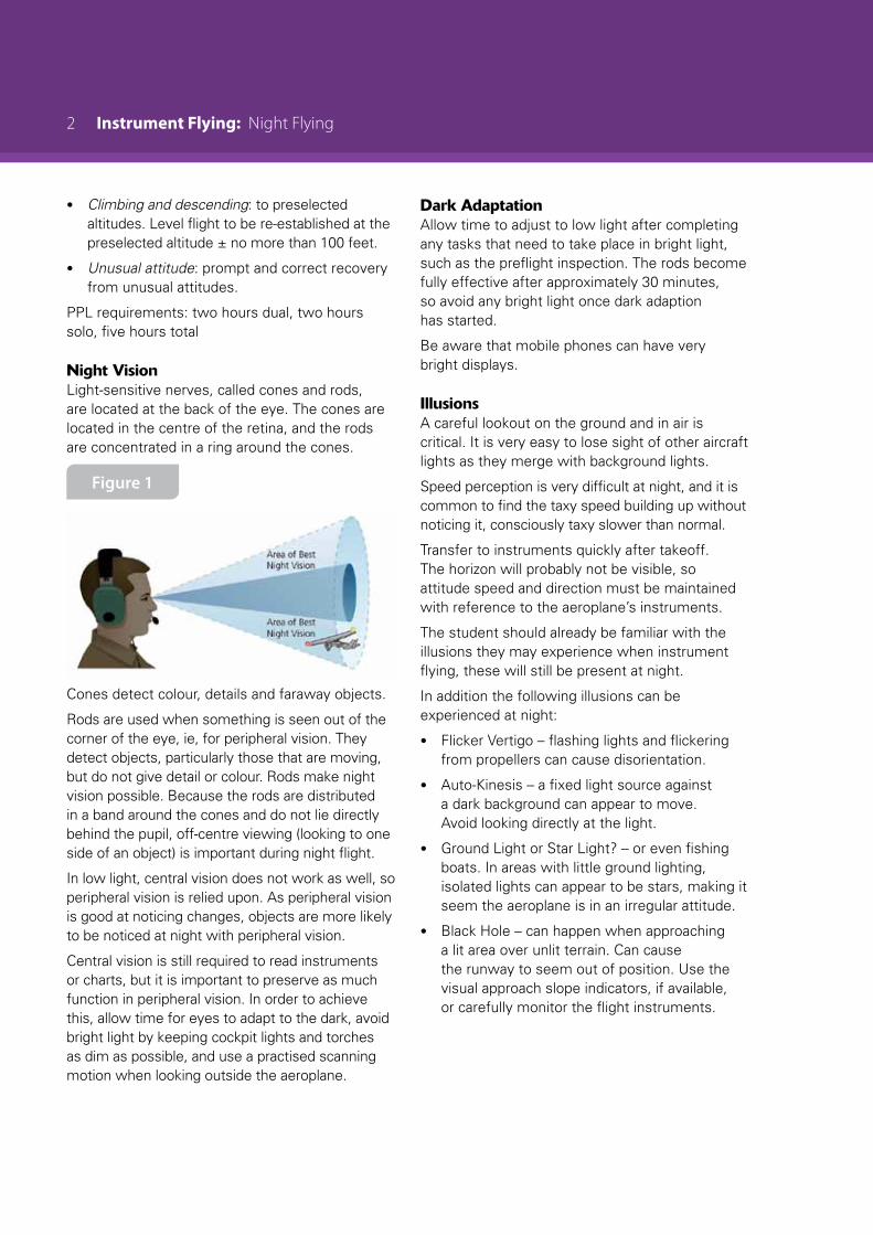
Night VisionLight-sensitive nerves, called cones and rods, are located at the back of the eye. The cones are located in the centre of the retina, and the rods are concentrated in a ring around the cones.
Figure 1
Cones detect colour, details and faraway objects.
Rods are used when something is seen out of the corner of the eye, ie, for peripheral vision. They detect objects, particularly those that are moving, but do not give detail or colour. Rods make night vision possible. Because the rods are distributed in a band around the cones and do not lie directly behind the pupil, off-centre viewing (looking to one side of an object) is important during night flight.
In low light, central vision does not work as well, so peripheral vision is relied upon. As peripheral vision is good at noticing changes, objects are more likely to be noticed at night with peripheral vision.
Central vision is still required to read instruments or charts, but it is important to preserve as much function in peripheral vision. In order to achieve this, allow time for eyes to adapt to the dark, avoid bright light by keeping cockpit lights and torches as dim as possible, and use a practised scanning motion when looking outside the aeroplane.
Dark AdaptationAllow time to adjust to low light after completing any tasks that need to take place in bright light, such as the preflight inspection. The rods become fully effective after approximately 30 minutes, so avoid any bright light once dark adaption has started.
Be aware that mobile phones can have very bright displays.
IllusionsA careful lookout on the ground and in air is critical. It is very easy to lose sight of other aircraft lights as they merge with background lights.
Speed perception is very difficult at night, and it is common to find the taxy speed building up without noticing it, consciously taxy slower than normal.
Transfer to instruments quickly after takeoff. The horizon will probably not be visible, so attitude speed and direction must be maintained with reference to the aeroplane’s instruments.
The student should already be familiar with the illusions they may experience when instrument flying, these will still be present at night.
In addition the following illusions can be experienced at night:
• Flicker Vertigo – flashing lights and flickering from propellers can cause disorientation.
• Auto-Kinesis – a fixed light source against a dark background can appear to move. Avoid looking directly at the light.
• Ground Light or Star Light? – or even fishing boats. In areas with little ground lighting, isolated lights can appear to be stars, making it seem the aeroplane is in an irregular attitude.
• Black Hole – can happen when approaching a lit area over unlit terrain. Can cause the runway to seem out of position. Use the visual approach slope indicators, if available, or carefully monitor the flight instruments.

Instrument Flying: Night Flying 3
EquipmentFor the preflight check a torch will be required, in particular a torch powerful enough to be able to see the detail required.
While carrying out the preflight, note the position of the aeroplane on the aerodrome and the position of other aircraft.
It is also advisable to wear a high visibility jacket, and to be conscious of personal safety.
All lights should be checked to ensure they are working, including but not limited to; navigation lights, anti-collision lights, strobe lights, taxi lights and landing lights. The pilot should also be familiar with their operation, how much can be seen with them and when they are used.
Internal aeroplane lighting, including the compass, must be operational and the pilot should know how to adjust the lighting levels.
The pilot’s personal night equipment should include:
• Torch, with spare batteries
• Pen attached to the flight log, and a spare nearby
• Mobile phone
• Watch
• Warm clothing and a survival kit
• May like to carry a spare handheld VHF radio or GPS
Familiarity with the AeroplaneIt is important to know the location of the controls and switches, so the pilot can operate them without needing to look at them. At this stage of their training the student should be familiar with the aeroplane.
Familiarity with the AerodromeAIP Vol 4 Aerodrome Charts Operational Data details the lighting available on the aerodrome – a thorough knowledge of lighting facilities is important.
Discuss the location, colour and if applicable, the direction of all aerodrome lighting, including apron, taxi, holding point, runway and approach lighting. If pilot activated lighting (PAL) is available discuss the operation of this.
Review ATC light signals.
Discuss the particular approach lighting available at the aerodrome, and how it is to be used, eg PAPI. Check that the student can decode the lighting codes, and they know where to find the decodes for those they cannot.
WeatherInadvertent IMC is more likely at night. Exercise extreme caution. It can be very difficult to recognise weather deterioration and extremely hard to determine if cloud is blocking the view of terrain.
At night there is less mixing in the air up to 2000 feet and the surface wind will lessen and back. This can also mean the surface wind is significantly different from the wind at circuit altitude.
When the night is overcast it will be much harder to identify cloud than it would be on a clear night.
Pay particular attention to the temperature/dew point relationship as an indicator of potential fog/low cloud.
EmergenciesDetail the procedures to carry out in the event of the following emergencies:
• Radio failure – follow the local procedure, use the aeroplane’s lights and squawk 7600
• Runway lighting failure – the flight will need to divert to another aerodrome where the lighting is operational. This will need to be checked during the planning stages.
• Landing light or navigation light failure – the flight can continue, but should end at the next landing.
• Internal light failure – the flight can continue, but should end at the next landing.
• Electrical failure – should be noticed before total failure because of the increased frequency of SADIE checks. Total failure is a serious event and the flight should land as soon as practicable. Use the standard
4 Instrument Flying: Night Flying
overhead rejoin procedure.
• Engine failure – is particularly difficult to deal with at night. If the surface can be seen in the moonlight, plan for a normal forced landing. If the ground cannot be seen, fly at the minimum descent speed (1.1 VS) and turn into wind. Do not use flap unless the ground can be seen. Landing lights should only be used from below 400 feet agl as the glare will reduce the ability to see beyond the light’s beam.
See the Night VFR GAP booklet for further information.
AirmanshipPreflight in the light if possible, otherwise use a good torch.
Correct use of taxi/landing lights and strobe light.
Consider the number of other aircraft in the circuit, as it can be hard to see other aircraft in the circuit at night.
Caution – illusions discussed above.
Fly at the Minimum Safe Altitude. This can be determined from the MFA figures on the VNCs.
Identify local landmarks/lighting patterns – if any disappear such as a neighbouring community –there is a strong likelihood of cloud or fog development.
Aeroplane ManagementMore frequent SADIE checks
Particular attention should be paid to dew on windscreens and frost on wings.
Cockpit layout familiarity
Trust the instruments
Human FactorsInstrument flying illusions will be present.
Night vision factors – 10/30 minute adaptation, health (I’MSAFE), importance of oxygen to brain/eye function, colour perception, depth perception, focus (cones/rods), focal length (myopia), black hole, lights/stars.
Air ExerciseOn the GroundTaxi slowly.
Recognise runway lighting position in peripheral vision as this is the landing perspective.
When lining up make sure to have a careful lookout for aircraft on the approach.
During takeoff use the runway lighting to keep on the centreline as a reference point in the distance may not be available.
Once airborne immediately transfer to instruments to establish the aeroplane attitude and speed, and a positive rate of climb.
When established in the climb, then a combination of instruments and visual reference can be used.
In the CircuitThe first circuit should be a familiarisation circuit. It is a chance to see the local area, and compare how it looks at night to how it looks in the day. It is also a chance to orientate and locate local landmarks and townships.
At night it can be difficult to see the runway lighting from the downwind position, care must be taken positioning the aeroplane downwind at the correct spacing.

Instrument Flying: Night Flying 5
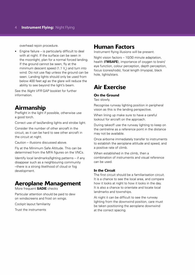
Approach and LandingAt night the runway edge lights must be used to judge the approach perspective.
Figure 2
During the landing it is important to use the runway perspective to judge the roundout and flare, not look for the ground in the landing light. The first few landings should be completed without the landing light.
Be careful of carrying too much speed when turning off the runway.
Airborne SequenceTeach night taxi principles and the various apron/runway/light recognition/application factors.
Take off and vacate the circuit to familiarise the student with the different night perspective i.e. illusions including black hole effect, lookout – other aircraft speed/direction, lack of depth perception, etc.
Return to the circuit and carry out approach and low overshoots to view the runway lighting perspectives of too low, on profile and too high.
Conduct night circuits, progressively introducing various emergencies.