instructions for ballistic whiz wheel · 2018-08-03 · instructions for ballistic whiz wheel...
TRANSCRIPT
Instructions for Ballistic Whiz Wheel
Overview
The Accuracy 1st Whiz Wheel is a ballistics calculator designed to back up, or replace an electronic
PDA. Used properly, the whiz wheel provides 0.1 MIL, or 0.25 MOA resolution for elevation and
windage corrections out to the transonic range for any given bullet/rifle combination. The whiz wheel
uses a generic sleeve in which you can place various wheels corresponding to different rifles, bullets,
and muzzle velocities for both MILS/Meters, and MOA/Yards units. The whiz wheel is able to account
for the effects of: density altitude (which covers any temperature and pressure combination), range,
both wind and moving targets of any speed from any direction, spin drift, and uphill/downhill shooting.
The whiz wheel also has the ability to be calibrated or trued to a given weapon system based on
observed POI (either muzzle velocity or BC can be trued).
This instruction manual is divided into four segments: Getting started, elevation, windage, and
truing.
Getting Started
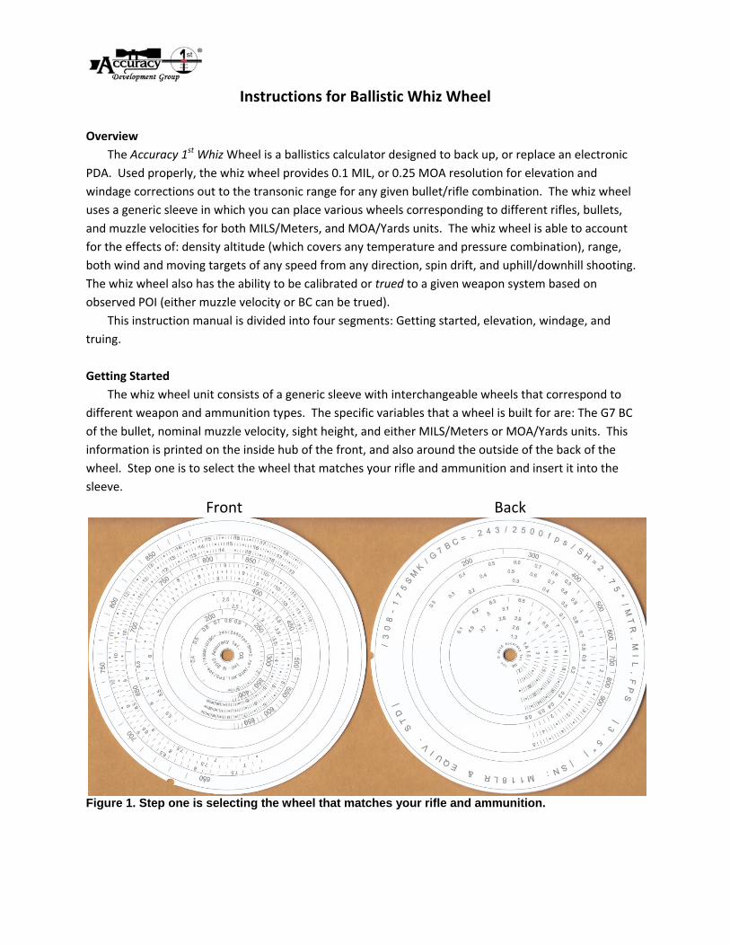
The whiz wheel unit consists of a generic sleeve with interchangeable wheels that correspond to
different weapon and ammunition types. The specific variables that a wheel is built for are: The G7 BC
of the bullet, nominal muzzle velocity, sight height, and either MILS/Meters or MOA/Yards units. This
information is printed on the inside hub of the front, and also around the outside of the back of the
wheel. Step one is to select the wheel that matches your rifle and ammunition and insert it into the
sleeve.
Front Back
Figure 1. Step one is selecting the wheel that matches your rifle and ammunition.
Elevation
When you have the appropriate wheel inserted into the sleeve, you can begin calculating a
ballistic solution.
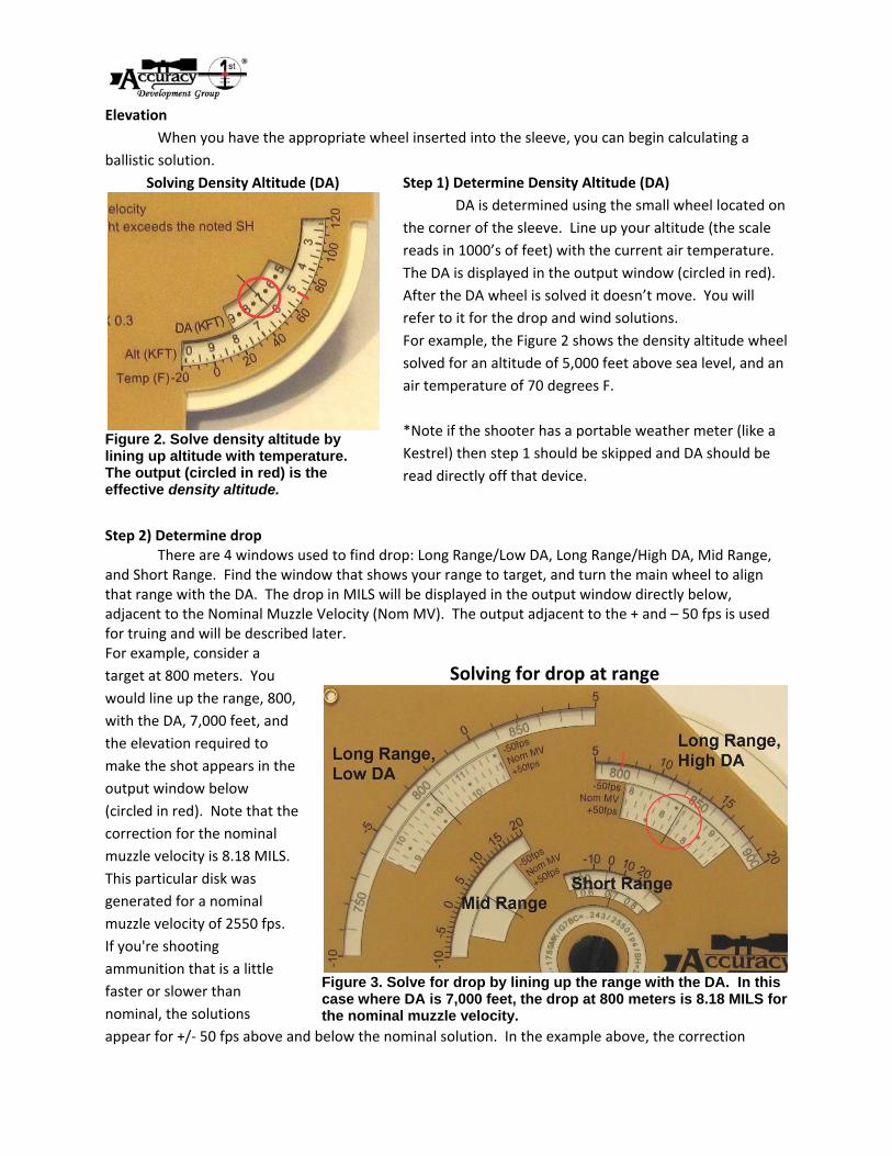
Step 1) Determine Density Altitude (DA)
DA is determined using the small wheel located on
the corner of the sleeve. Line up your altitude (the scale
reads in 1000’s of feet) with the current air temperature.
The DA is displayed in the output window (circled in red).
After the DA wheel is solved it doesn’t move. You will
refer to it for the drop and wind solutions.
For example, the Figure 2 shows the density altitude wheel
solved for an altitude of 5,000 feet above sea level, and an
air temperature of 70 degrees F.
*Note if the shooter has a portable weather meter (like a
Kestrel) then step 1 should be skipped and DA should be
read directly off that device.
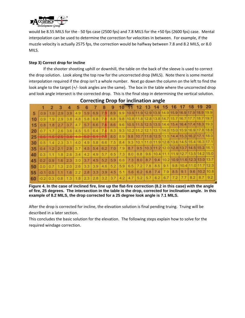
Step 2) Determine drop There are 4 windows used to find drop: Long Range/Low DA, Long Range/High DA, Mid Range, and Short Range. Find the window that shows your range to target, and turn the main wheel to align that range with the DA. The drop in MILS will be displayed in the output window directly below, adjacent to the Nominal Muzzle Velocity (Nom MV). The output adjacent to the + and – 50 fps is used for truing and will be described later. For example, consider a
target at 800 meters. You
would line up the range, 800,
with the DA, 7,000 feet, and
the elevation required to
make the shot appears in the
output window below
(circled in red). Note that the
correction for the nominal
muzzle velocity is 8.18 MILS.
This particular disk was
generated for a nominal
muzzle velocity of 2550 fps.
If you're shooting
ammunition that is a little
faster or slower than
nominal, the solutions
appear for +/‐ 50 fps above and below the nominal solution. In the example above, the correction
Solving Density Altitude (DA)
Figure 2. Solve density altitude by lining up altitude with temperature. The output (circled in red) is the effective density altitude.
Solving for drop at range
Figure 3. Solve for drop by lining up the range with the DA. In this case where DA is 7,000 feet, the drop at 800 meters is 8.18 MILS for the nominal muzzle velocity.
would be 8.55 MILS for the ‐ 50 fps case (2500 fps) and 7.8 MILS for the +50 fps (2600 fps) case. Mental
interpolation can be used to determine the correction for velocities in between. For example, if the
muzzle velocity is actually 2575 fps, the correction would be halfway between 7.8 and 8.2 MILS, or 8.0
MILS.
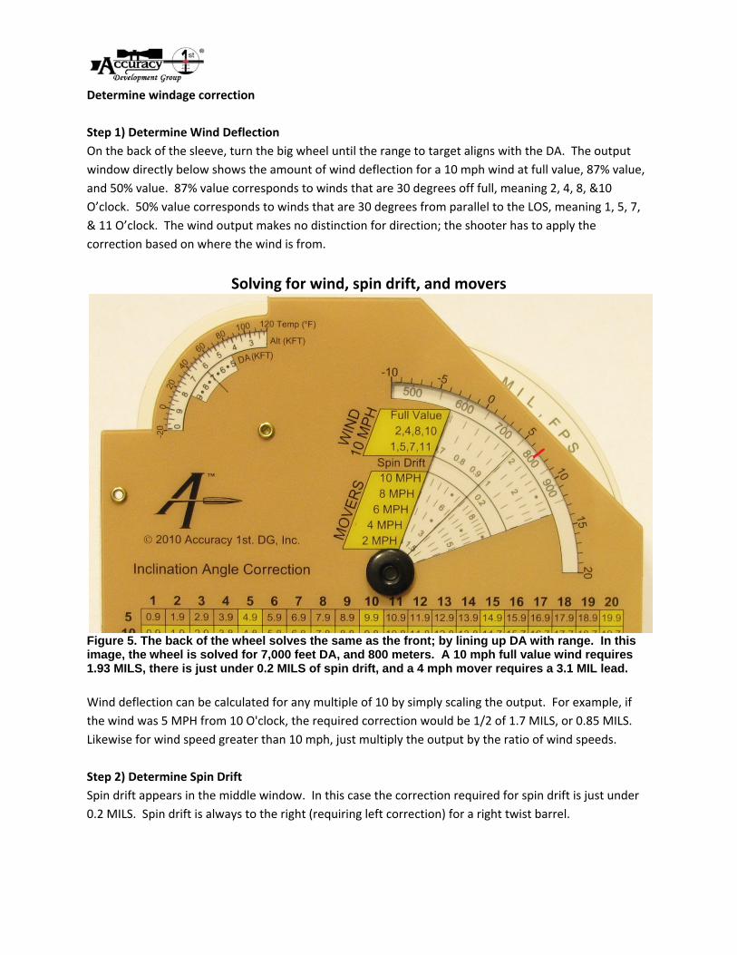
Step 3) Correct drop for incline
If the shooter shooting uphill or downhill, the table on the back of the sleeve is used to correct
the drop solution. Look along the top row for the uncorrected drop (MILS). Note there is some mental
interpolation required if the drop isn’t a whole number. Next go down the column on the left to find the
look angle to the target (+/‐ look angles are the same). The box in the table where the uncorrected drop
and look angle intersect is the corrected drop. This is the final step in determining the vertical solution.
Correcting Drop for inclination angle
Figure 4. In the case of inclined fire, line up the flat-fire correction (8.2 in this case) with the angle of fire, 25 degrees. The intersection in the table is the drop, corrected for inclination angle. In this example of 8.2 MILS, the drop corrected for a 25 degree look angle is 7.1 MILS.
After the drop is corrected for incline, the elevation solution is final pending truing. Truing will be
described in a later section.
This concludes the basic solution for the elevation. The following steps explain how to solve for the
required windage correction.
Determine windage correction
Step 1) Determine Wind Deflection
On the back of the sleeve, turn the big wheel until the range to target aligns with the DA. The output
window directly below shows the amount of wind deflection for a 10 mph wind at full value, 87% value,
and 50% value. 87% value corresponds to winds that are 30 degrees off full, meaning 2, 4, 8, &10
O’clock. 50% value corresponds to winds that are 30 degrees from parallel to the LOS, meaning 1, 5, 7,
& 11 O’clock. The wind output makes no distinction for direction; the shooter has to apply the
correction based on where the wind is from.
Solving for wind, spin drift, and movers
Figure 5. The back of the wheel solves the same as the front; by lining up DA with range. In this image, the wheel is solved for 7,000 feet DA, and 800 meters. A 10 mph full value wind requires 1.93 MILS, there is just under 0.2 MILS of spin drift, and a 4 mph mover requires a 3.1 MIL lead.
Wind deflection can be calculated for any multiple of 10 by simply scaling the output. For example, if
the wind was 5 MPH from 10 O'clock, the required correction would be 1/2 of 1.7 MILS, or 0.85 MILS.
Likewise for wind speed greater than 10 mph, just multiply the output by the ratio of wind speeds.
Step 2) Determine Spin Drift
Spin drift appears in the middle window. In this case the correction required for spin drift is just under
0.2 MILS. Spin drift is always to the right (requiring left correction) for a right twist barrel.
Step 3) Determine Lead for Moving Target
The speed of a mover refers to the line of sight crossing rate of the moving target. For example, if a
target is moving 10 mph, but is quartering away at a 30 degree angle to the line of sight, the actual line
of sight crossing rate is only 5 mph. The crossing rate of a target is calculated the same as wind. For
movers that are traveling at 2, 4, 8, and 10 O'clock to the line of sight, the line of sight crossing rate is
87% of the targets true speed. For movers that are traveling at 1, 5, 7, or 11 O'clock to the line of sight,
the line of sight crossing rate is 50% of the targets true speed. For movers that are traveling at 3 or 9
O'clock to the line of sight, the crossing rate is the full value of the targets speed. Targets moving
parallel to the line of sight (12 and 6 O'clock) have no crossing rate, and no lateral lead is necessary.
Step 4) Add windage effects
The effects of wind, spin drift, and moving target are all cumulative. This means they simply add up to
the final solution. For example, in the above case where the wheel is solved for 7,000 feet DA, and 800
meters, if there was a 10 mph 1 O'clock wind that would require 1 MIL right. Spin drift is .2 MILS, and
it's always a correction to the left. So for a still target, the total windage correction in this case is 0.8
MILS left. If there were a target moving at 4 mph from left to right, it would require a 3.1 MIL lead in
addition to the correction already applied for the wind and spin drift.
Notice that the small DA wheel in the corner remains solved, and is visible from both sides of the device.
This is so you can reference the DA value as the wheel is solved for windage and elevation.
This concludes the basic elevation and windage solution for the whiz wheel. When the appropriate
wheel is solved properly, the output should result in first round hits out to the max range of the wheel.
However, due to variations in the BC, and muzzle velocity of different lots of bullets and weapon specific
effects, it's possible that the whiz wheel outputs a correction that's not 100% accurate for a given rifle.
In this case, the wheel can be trued.
How Truing works
There is a process to true, or calibrate the whiz wheel to an observed trajectory from a particular rifle.
The solution can either be trued based on muzzle velocity or BC. The following instructions explain how
each method works.
Truing based on muzzle velocity
Step 1) Calculate a complete, nominal firing solution as described above.
Step 2) Fire a shot or group of shots and observe the impact(s).
Step 3) Figure out what the correct firing solution should have been to center the shot or group.
Step 4) with the wheel solved for range and DA, look in the output window above and below the
nominal solution to see how much effect a + or – 50 fps difference in MV makes.
Step 5) See if the + or ‐ 50 fps output is closer to the observed drop, or if the solution lies part way
between the different solutions given.
Step 6) Write down or memorize the MV bias for the particular weapon and apply it for all future
solutions.
Truing based on Ballistic Coefficient (BC)
Step 1) Calculate a complete, nominal firing solution as described above.
Step 2) Fire a shot or group of shots and observe the impact(s).
Step 3) Figure out what the correct firing solution should have been to center the shot or group.
Step 4) Turn the wheel until the observed amount of drop is displayed in the output window adjacent to
the Nominal MV.
Step 5) Note the DA which now aligns with the range. The difference between that DA, and the actual
DA is the DA bias which applies for the ‘trued’ solution.
Note that truing for DA has the exact same effect as truing the BC of the bullet.
Other factors to keep in mind for best results
1. Always use a wheel that matches your actual ammunition and sight height.
2. The whiz wheel only works for trajectories that are zeroed for 100 meters/yards.
3. If available, use a Kestrel or other weather meter to measure Density Altitude directly. The small DA
wheel is included on the whiz wheel as a fail‐safe in case a better source isn't available. However since
it's relying on estimated temperature and altitude, the accuracy of its output is limited.
4. it’s critically important to know the actual movement of your reticle, or reticle scale factor. In other
words, if 20 clicks should move the POI 2.0 MILS, but it moves 2.15 MILS, this needs to be accounted for.