instruction sheet / instruction de service 06/2008 · instruction sheet / instruction de service...
TRANSCRIPT

Instruction sheet / Instruction de service06/2008
TeSys contactors / Contacteurs TeSys
TeSys LC1B & CV3Variable composition contactors / Contacteurs à composition variable
LC1 BRpp CV3 RBpp
LC1 BPpp CV3 PBpp
LC1 BLpp CV3 LBpp LC1 BMpp CV3 MBpp


�AAV79�65-0�
ENG
LISH
FRA
NC
AIS
ContentsSafety instructions and precautions 3Lifting the contactor 4Installation 5Dimensions 6Mounting 7Mechanical interlock 8Control diagrams 10Simplified troubleshooting guide 11Maintenance 12Setting characteristics 13Replacement coils and accessories 14For single-pole contactors �4For 2-pole contactors �5For 3-pole contactors �6For 4-pole contactors �7
Replacement parts 18
SommaireConsignes de sécurité et précautions 21Levage du contacteur 22Mise en œuvre 23Encombrements 24Montage 25Condamnation mécanique 26Schémas de commande 28Guide de dépannage simplifié 29Entretien 30Caractéristiques de réglage 31Bobines et éléments à associer 32Pour contacteurs unipolaires 32Pour contacteurs bipolaires 33Pour contacteurs tripolaires 34Pour contacteurs tétrapolaires 35Pièces de rechange 36

2 AAV79�65-0�

�AAV79165-01
ENG
LISH
Safety instructions and precautions
Important notesRestricted liabilityElectrical equipment should be serviced and maintained by qualified personnel only.No responsibility is assumed by Schneider Electric for any consequence arising out of the use of this manual. This document is not intended as an instruction manual for untrained persons.
Device operationThe user is responsible for checking that the rated characteristics of the device are suitable for its application. The user is responsible for reading and following the device's operating and installation instructions before attempting to commission or maintain it. Failure to follow these instructions can affect device operation and constitute a hazard for people and property.
Safety symbols and messagesRead these instructions carefully and look at the equipment to become familiar with the device before trying to install, operate, service or maintain it. The following special messages may appear throughout this bulletin or on the equipment to warn of potential hazards or to call attention to information that clarifies or simplifies a procedure.
Risk of electric shock
ANSI symbol IEC symbol
The addition of either symbol to a "Danger" or "Warning" safety label on a device indicates that an electrical hazard exists, which will result in death or personal injury if the instructions are not followed.
Safety alert
This is the safety alert symbol. It is used to alert you to potential personal injury hazards and prompt you to consult the manual. Obey all safety instructions that follow this symbol in the manual to avoid possible injury or death.
Safety messages
DANGERDANGER indicates an imminently hazardous situation, which, if not avoided, will result in death, serious injury or property damage.
CAUTIONCAUTION indicates a potentially hazardous situation which, if not avoided, could result in minor or moderate injury or property damage.
Documentation
Catalog TeSys LC1 B and CV� contactors are described in the "Variable composition contactors" catalog, ref. DIA1ED2070702EN.Instruction sheetThe instruction sheet supplied with each contactor has two functions:
A concise installation and commissioning guide for integratorsA reminder for operators
It is advisable to keep it near the contactor.
bb
TeSys LC1 B & CV3

� AAV79165-01
ENG
LISH
Lifting the contactor
References Weight in kgLC1BL�1 31.000LC1BL32 44.000LC1BL�� 57.000LC1BL�� 71.000LC1BM�1 32.000LC1BM32 45.000LC1BM�� 58.000LC1BM�� 71.000LC1BP�1 41.000LC1BP32 65.000LC1BP�� 94.000LC1BP�� 120.000LC1BR�1 52.000LC1BR32 85.000LC1BR�� 129.000LC1BR�� 160.000
CAUTIONLIFTING BAR BREAKAGE HAZARD
Do not use the lifting bars for mounting the contactor.
Use appropriate personal protective equipment and follow safe work practices. See local regulation.Failure to follow these instructions can result in serious injury or equipment damage.
b
b
TeSys LC1 B & CV3

5AAV79165-01
ENG
LISH
Installation
MountingIn general, bar-mounted contactors are installed on two vertical DZ5MZ uprights. The fixing centers of the support bars are standardized, as is the diameter of the fixing holes.At the end of each bar there is a cut-out with notches, one vertical and the other horizontal.For CV3p B and LC1Bp contactors sizes L, M, P and R, the use of LA9 B10� mounting brackets is recommended.
CAUTIONLIFTING BAR BREAKAGE HAZARD
Do not use the lifting bars for mounting the contactor.Use appropriate personal protective equipment and follow safe work practices.
See local regulation.Failure to follow these instructions can result in serious injury or equipment damage.
bb
Contactor mounting position23°
23°
M12
4 x M10
Mounting accessoriesDescription Contactors Reference Weight
Type Size kgBar mounting bracket36 mmfixing centers 120 or 150 mm
LC1 B and CV�
L to R LA9 B103 1.650
Note: Only 2 of the 4 M10 nuts are used depending on the fixing center.
Mounting accessoriesDescription Specification Length Sold in
lots ofUnit reference Weight
LA9 B103 mm kg
Pre-drilled "Z" profile uprights suitable for building chassis for variable composition contactors
– 1020 – DZ6 MZ121 2.590
1320 – DZ6 MZ151 3.350
LA9 B103
DZ6 MZppp
55
DZ6 MZppp
551420 – DZ6 MZ161 3.600
1620 – DZ6 MZ181 4.110
1820 – DZ6 MZ200 4.620
1920 – DZ6 MZ211 4.870
Notched clamp nuts for mounting on pre-drilled "Z" profile uprights
M6 – 100 DZ5 MF6 –
M8 – 100 DZ5 MF8 –
Square nutsfor mounting on pre-drilled "Z" profile uprights
M10 – 10 DZ6 MZ904 –
Recommended mounting using mounting brackets
Mounting possible for bars y 445 mm
TeSys LC1 B & CV3

6 AAV79165-01
ENG
LISH
Dimensions
Connection bar cut-outs CV3 and LC1 B single-, 2-, or 3-pole contactorsa
TS
T
44
330
P P Q13015
30ML
15
Fixing screws: Ø 8 for CV3 and LC1 B size L Ø 10 for all other contactor sizes
Common side view CV3 and LC1 B 4-pole contactors
260
R290185
N85c
bc
365
330
P30
15
30M1L
P Q151M2
15
CV3 and LC1 Bcontactor size L M P RNumber of poles (1) 1 2 3 4 1 2 3 4 1 2 3 4 1 2 3 4
a mm 50 50 50 50 6� 6� 6� 6� 100 100 100 100 125 125 125 125b mm 59 59 59 59 55 55 55 55 55 55 55 55 50 50 50 50c mm 16 16 16 16 20 20 20 20 20 20 20 20 25 25 25 25L mm 345 445 540 760 345 445 540 760 385 540 760 1065 445 635 885 1065M mm 285 �85 �80 – 285 �85 �80 – 325 �80 700 – �85 575 825 –M1 mm – – – �08 – – – �08 – – – �55 – – – �55M2 mm – – – 392 – – – 392 – – – 550 – – – 550N mm 121 121 121 121 125 125 125 125 125 125 125 125 1�0 1�0 1�0 1�0P mm 100 100 100 100 100 100 100 100 150 150 150 150 195 195 195 195Q1 mm 100 100 100 100 100 100 100 100 110 110 110 110 1�0 1�0 1�0 123R mm 122 122 122 122 157 157 157 157 17� 17� 17� 17� 17� 17� 17� 17�S mm 10 10 10 10 17 17 17 17 20 20 20 20 20 20 20 20T mm �0 �0 �0 �0 �0 �0 �0 �0 60 60 60 60 60 60 60 60Ø mm 9 9 9 9 11 11 11 11 11 11 11 11 11 11 11 11
(1)N/O main poles type "P"
X2
X1
Minimum electrical clearanceValues X1 and X2 are given for a breaking capacity of 10 In (3-phase a current).
CV3 and LC1 Bcontactor size L M P R3-phase a voltage
380/440 V X1 100 100 150 200X2 150 150 200 250
500 V X1 100 100 150 200X2 150 150 220 250
660/690 V X1 150 150 200 200X2 200 200 250 250
1000 V X1 200 200 200 250X2 250 250 250 �00
TeSys LC1 B & CV3

7AAV79165-01
ENG
LISH
Mounting
DANGER Connecting the busbars
ELECTRIC SHOCK, EXPLOSION OR ARC FLASH HAZARD
This equipment must be installed and used by qualified personnel only.
Turn off all power supplying the contactor and the equipment in which it is installed before working on it.
Always use a properly rated voltage sensing device to confirm that power is off.
Replace all devices, doors and covers before turning the contactor power back on.
Replace all other protection devices before energizing the power equipment.
Use appropriate personal protective equipment and follow safe electrical work practices. See local regulation.Failure to follow these instructions will result in death, serious injury or equipment damage.
b
b
b
b
b
b
LC1BLCV3LB
LC1BMCV3MB
LC1BPCV3PB
LC1BRCV3RB
�xM8
�x M10
�x M10
�x M10
1� mm 16 mm 16 mm 16 mm
Tightening torque 25 to 28 Nm �5 to �7 Nm �5 to �7 Nm �5 to �7 Nm
Position of busbars before tighteningCorrect mounting Incorrect mounting
Maximum clearance before tightening
J < 1 mm
J < 1 mm
TeSys LC1 B & CV3

8 AAV79165-01
ENG
LISH
Mechanical interlock
DANGER Mounting the mechanical interlock on contactors of identical sizeELECTRIC SHOCK, EXPLOSION OR ARC FLASH
This equipment must be installed and used by qualified personnel only.
Turn off all power supplying the contactor and the equipment in which it is installed before working on it.
Always use a properly rated voltage sensing device to confirm that power is off.
Replace all devices, doors and covers before turning the contactor power back on.
Replace all other protection devices before energizing the power equipment.
Use appropriate personal protective equipment and follow safe electrical work practices. See local regulation.Failure to follow these instructions will result in death, serious injury or equipment damage.
b
b
b
b
b
b
600
L
References L LC1BL�1 ��5LC1BL32 ��5LC1BL�� 5�0LC1BL�� 760LC1BM�1 ��5LC1BM32 ��5LC1BM�� 5�0LC1BM�� 760LC1BP�1 �85LC1BP32 5�0LC1BP�� 760LC1BP�� 1065LC1BR�1 ��5LC1BR32 6�5LC1BR�� 885LC1BR�� 1065
Mechanical interlock referencesWithout mounting bearings With mounting bearings
EZ2 LB0601 EZ2 LB0602
TeSys LC1 B & CV3

9AAV79165-01
ENG
LISH
Mechanical interlock
Adjusting the mechanical interlock
Upper contactor
A =
(E–1
12) 4
88
E =
600
A
B
D
E
C
1 m
m
G
F
F
Lower contactor
G Direction of rotation to lift the mechanical interlock latchF Bar
Disconnect the power circuit voltage.Check that there is no voltage on the power circuit.Loosen screws A and C.Close the lower contactor electrically or mechanically. Turn the rod B to move the interlock latch E 1 mm away from the interlock finger D.Lock this in place using screws A and C.Open the lower contactor.Close the upper contactor.Make sure that the interlock latch E does not rub on the interlock finger D.
1.2.3.4.
5.6.7.8.
TeSys LC1 B & CV3

10 AAV79165-01
ENG
LISH
Control diagrams
AC control circuit supply with rectifier and economy resistor
(1)
(2)
(1)Optional protection relay. Must be latching type for 2-wire control.(2) Rr: Economy resistor
DC control circuit supply with economy resistor
(1)
(1) Rr: Economy resistor
It is essential to check that the control circuit contacts have ratings compatible with the voltage and power consumption of the contactor coil. If not, an intermediate "KA" auxiliary relay must be added and wired as shown.
TeSys LC1 B & CV3
�-wire control
2-wire control
�-wire control
2-wire control

11AAV79165-01
ENG
LISH
Simplified troubleshooting guideTeSys LC1 B & CV3
DANGERELECTRIC SHOCK, EXPLOSION OR ARC FLASH HAZARD
This equipment must be installed and used by qualified personnel only.Turn off all power supplying the contactor and the equipment in which it is installed before working on it.Always use a properly rated voltage sensing device to confirm that power is off.To check the control circuit with the power on, make sure you take all necessary precautions to avoid electric shock.Replace all devices, doors or covers, arc chambers, and blow-out poles before turning the contactor power back on.Replace all other protection devices before energizing the power equipment.Use appropriate personal protective equipment and follow safe electrical work practices. See local regulation.
Failure to follow these instructions will result in death, serious injury or equipment damage.
bbbbbbb
Type of control circuit
Checks to be performed Corrective action
The contactor does not pick upc or a, with or without economy resistor
Make sure that the control voltage corresponds to that of the contactor.
Adapt the control circuit voltage or the contactor.
c or a, with economy resistor Make sure that voltage is present at the contactor's control circuit terminals.
Check the control circuit.
c or a, with or without economy resistor
Check the control voltage after the rectifier. The DC voltage is almost equal to the AC voltage.
Replace the rectifier.
c or a, with economy resistor Check the condition and adjustment of the economy resistor contact.
If the contacts are worn, replace the ZC4GM2. If one of the moving contacts is not touching the fixed contact, re-adjust if possible, or contact our technical support service.
c or a, with or without economy resistor
Check the continuity of the coil(s). Replace the faulty coil.
c Make sure that the wire or shunt connecting the 2 coils is present and in good condition.
Replace or reposition the wire or shunt correctly.
c or a, with or without economy resistor
Check the wiring, wire by wire. Replace the faulty wire.
The contactor does not remain closedc or a, with or without economy resistor
Make sure that the control supply circuit has sufficient power (corresponding at least to that of the inrush power of the most powerful contactor).
Increase the control circuit power.
c or a, with or without economy resistor
Make sure the power supply wires are sufficiently sized, in particular for voltages of less than 110 V.
Increase the wire size to adapt their c.s.a to the contactor inrush current (see the coils tables on pages 1� to 17).
c or a, with economy resistor Check that the economy resistor contact is set correctly. Re-adjust if possible or contact our technical support service.
c or a, with economy resistor Check the continuity of the economy resistor circuit by closing the fixed and moving contacts mechanically. The circuit impedance should be equal to the impedance of the coil plus the economy resistors.
Replace the faulty component (wire or resistor).
c or a, with or without economy resistor
Make sure that there is no mechanical stiffness on the contactor shaft.
Find the cause and eliminate it.
c or a, with or without economy resistor (except direct c)
Check that the moving circuit is not rubbing on the stop supports.
Loosen the 2 screws on the moving circuit, re-center it and, if necessary, move it down to prevent it rubbing.
c or a, with economy resistor Check that the mechanical interlock is correct set correctly. Adjust the mechanical interlock.
The contactor drops out slowlyc or a, with economy resistor Make sure that the circuit faces are clean. Clean the pole faces using a dry or slightly damp cloth.
c or a, with or without economy resistor
Make sure that there is still a gap (difference between the upper and lower faces and the middle face on the moving circuit for the laminated circuits and non-magnetic washer for the solid circuits).
Replace the electromagnet.
c or a, with or without economy resistor
Make sure that the pole pressure is not too weak. Adjust the pressure (replace the springs if necessary if they have collapsed).
c or a, with or without economy resistor
Make sure that pole compression is not too low. If compression is less than 50% of its original value, replace the contactor contacts and reset the compression settings.Note: Never adjust the compression value on worn contacts.
c or a, with or without economy resistor
Check the condition and voltage of the return spring. Adjust or replace the return spring. Adjustment is based on the pick-up voltage.
The contactor does not drop outc or a, with or without economy resistor
Make sure that there is no control voltage. Disconnect the control circuit.
c or a, with or without economy resistor
Make sure that there are no soldered contacts. 1. Disconnect the power circuit.2. Try to open the contactor manually using a lever. If you cannot open it manually, remove the contacts and replace them with new ones (see procedure on page 12).

12 AAV79165-01
ENG
LISH
Maintenance
DANGERELECTRIC SHOCK, EXPLOSION OR ARC FLASH HAZARD
This equipment must be installed and used by qualified personnel only.Turn off all power supplying the contactor and the equipment in which it is
installed before working on it.Always use a properly rated voltage sensing device to confirm that power is off.Replace all devices, doors and covers before turning the contactor power back
on.Replace all other protection devices before energizing the power equipment.Use appropriate personal protective equipment and follow safe electrical work
practices. See local regulation.Failure to follow these instructions will result in death, serious injury or equipment damage.
bb
bb
bb
These contactors do not require any special maintenance.The contacts should never be filed or greased; they can be lightly sanded if necessary.Contacts which have performed numerous breaks may look as if they are worn. It is only by checking the compression gap that the degree of wear can be evaluated (see procedure below).
Contact compression checking procedureElectromagnetcore
Coil
Armature
Return spring
Compression should be checked for each individual contact in each set of contacts.Disconnect the power supply.Make the fixed and moving contact points on a set of contacts touch by closing the electromagnet and measuring the gap "e" between the fixed and moving circuit above the electromagnet (see page 1�).The contact between both contact points can be verified:b Electrically, if possible, using an ohmmeter or a pilot light (to find the exact point at which the contacts are touching)b Or mechanically by placing a thin sheet of paper between the contacts (so that they hold the paper in place without crushing it)
1.2.
Important:
Setting closing travel (E) and compression gap (e) Never adjust the compression gap if it is more than 50% of its original value.If the compression gap "e" is between 30 and 50% of its initial value on a set of contacts, replace all of the contactor's contacts and proceed with the adjustments (see below).The compression gap "e" can only be adjusted on new contacts.
Contact replacement and adjustment procedureRemove the old contacts.Clean the inner side walls of the arc chambers by scraping.Insert all the new contacts and tighten to 21 Nm.Loosen all the locknuts on the HC 8 x 45 adjustment screws.Tighten all the HC 8 x �5 screws so as to keep the moving contacts away from the fixed contacts. Close the electromagnet mechanically, placing a wedge between the fixed circuit and the moving circuit equal to the required compression value + 0.5 mm (for example, for a 10 mm compression gap, insert a 10.5 mm wedge at the upper ends of the fixed and moving circuits).Loosen the screw on the first set of contacts until both contacts touch, then retighten by 1/8 of a turn and lock the nut.Follow the same procedure for each set of contacts.Close the electromagnet electrically or mechanically.Check the pressure of each set of contacts:b Either by pulling directly at the center of the contact point of the actuating finger with a spring scaleb Or by pulling with a lever (W80751732) and a spring scale on the iron hand for PA2 poles or a lever (W80765164) and a spring scale on the moving contact support bracket for PA1, PA3 and PA5 poles.(When using a lever, make sure that you take its multiplication coefficient into account in the measurement.)Check the tightness of the locknuts.
1.2.3.4.5.
6.
7.
8.9.10.
11.
Setting the force F of the pole contacts
Fixed contact
Moving contact
Compressiongap setting
Pole pressuresettingPole spring
Fixed contact
Moving contact
Compressiongap setting
Pole pressuresettingPole spring
TeSys LC1 B & CV3

1�AAV79165-01
ENG
LISH
Setting characteristics
Setting characteristics of LC1 B and CV3 contactors (sizes L to R)ElectromagnetElectromagnet EB5 KB50 Setting closing travel (E) and compression gap (e)
Electromagnetcore
Coil
Armature
Return spring
PolesComplete pole N/O pole
Fixed contact
Moving contact
Compressiongap setting
Pole pressuresettingPole spring
Setting characteristics on c or a sup ply with economy resistor (and rectifier for a)CV3 or LC1 B contactor size L M P R
Electromagnet EB5 KB50 EB5 KB50 EB5 KB50 EB5 KB50Armature closing travel (E) mm 30 ±2 30 ±2 30 ±2 30 ±2Compression travel (e) mm 10 ±0.5 10 ±0.5 10 ±0.5 10 ±0.5
Economy resistor contact Opening travel (e) mm 8-1 +2.5 8-1 +2.5 8-1 +2.5 8-1 +2.5
Coil WB1 KBppp WB1 KBppp WB1 KBppp WB1 KBppp
Pull-in voltage V 0.73 ±0.02 Uc 0.73 ±0.02 Uc 0.73 ±0.02 Uc 0.73 ±0.02 UcDrop-out voltage V 0.25…0.5 Uc 0.25…0.5 Uc 0.25…0.5 Uc 0.25…0.5 Uc
N/O poleContact pressure force setting (F) per pole according to the contactor composition
1 pole daN �0 ±� �0 ±� �0 ±� (1) �0 ±� (2)2 poles daN �0 ±� �0 ±� �0 ±� (1) �0 ±� (2)� poles daN �0 ±� �0 ±� �0 ±� (1) �0 ±� (2)� poles daN �0 ±� �0 ±� �0 ±� (1) �0 ±� (2)
(1) Each pole has 2 contacts; the force must be applied evenly to each of these contacts.(2) Each pole has 3 contacts; the force must be applied evenly to each of these contacts.
TeSys LC1 B & CV3

1� AAV79165-01
ENG
LISH
Replacement coils and accessoriesFor single-pole contactors
TeSys LC1 B & CV3
ReferencesThe same coils are used for c or a contactor control supply.
For DC operation, the following must be associated with the coil:1 economy resistor arrangement (resistors + 1 or 2 auxiliary contact(s) or 1
contactor)For 50 to 400 Hz AC operation, the following must be associated with the coil: 1 individual rectifier (to be wired)1 economy resistor arrangement (resistors + auxiliary contact(s) or 1 contactor)
wired into the rectified current side
bv
bvv
WB1 KBppp
Operating range min.-max. (1)
Coil Economy resistor Rectifier (for a only)
Coil Weight
DC AC Resistance at 20°C ±10%
I inrush ±10% at Un max.
Resistor Contact Reference ReferenceUnit reference Total
resistanceQty Reference
V V W A W kg�7-51 – 5.1 10.3 DR2 SC0270 270 1 ZC4 GM2 – WB1 KB155 1.12052-56 – 5.9 9.5 DR2 SC0330 ��0 1 ZC4 GM2 – WB1 KB132 1.12057-6� – 7.3 8.9 DR2 SC0390 �90 1 ZC4 GM2 – WB1 KB123 1.12065-68 – 9.5 7.1 DR2 SC0560 560 1 ZC4 GM2 – WB1 KB133 1.12069-79 – 11.6 6.9 DR2 SC0680 680 1 ZC4 GM2 – WB1 KB121 1.12080-87 – 16.2 5.3 DR2 SC0820 820 1 ZC4 GM2 – WB1 KB130 1.12088-9� – 19.9 4.7 DR2 SC1000 1000 1 ZC4 GM2 – WB1 KB140 1.12095-108 110-125 25.5 4.3 DR2 SC1200 1200 1 ZC4 GM2 DR5 TE1U WB1 KB134 1.120109-1�6 126-155 33.1 4.2 DR2 SC1800 1800 1 ZC4 GM2 DR5 TE1U WB1 KB124 1.1201�7-151 156-17� 50.9 � DR2 SC2700 2700 2 ZC4 GM2 DR5 TE1U WB1 KB122 1.120152-166 17�-191 61.36 2.7 DR2 SC3300 ��00 2 ZC4 GM2 DR5 TE1U WB1 KB135 1.120167-189 192-216 78.4 2.4 DR2 SC3900 �900 2 ZC4 GM2 DR5 TE1U WB1 KB136 1.120190-221 217-256 94.8 2.3 DR2 SC4700 �700 2 ZC4 GM2 DR5 TE1U WB1 KB139 1.120222-243 257-280 123.9 1.9 DR2 SC6800 6800 1 LC1 DT20 LDS135 DR5 TE1U WB1 KB125 1.120244-267 281-307 159.9 1.7 DR2 SC8200 �700+ ��00 1 LC1 DT20 LDS135 DR5 TE1S WB1 KB137 1.120
268-318 �08-�65 199.6 1.6 DR2 SC1001 5600+ �700 1 LC1 DT20 UDS135 DR5 TE1S WB1 KB126 1.120
�19-�05 �66-�6� 247.4 1.6 DR2 SC1201 6800+ 5600 1 LC1 DT20 TDS135 DR5 TE1S WB1 KB138 1.120
�06-��6 �6�-500 382 1.1 (2) DR2 SC1001 20,000 1 LC1 DT20 VDS135 DR5 TE1S WB1 KB127 1.120��7-500 – 506.7 1 (3) DR2 SC1201 24,000 1 LC1 DT20 RDS135 – WB1 KB128 1.120(1) For supply voltages of less than 110 V, beware of voltage drops caused by the inrush current.(2) 2 resistors in series: 2 x 10,000 Ohm(3) 2 resistors in series: 2 x 12,000 Ohm
SpecificationsAverage coil consumption (low sealed consumption):DC: Inrush 380…520 W, sealed 0.15…0.20 WAC (with rectifier): Inrush 450…620 VA, sealed 0.15…0.20 VATime constant when sealed 25 msEconomy resistor consumption: 7…10 WOperating cycles/hour at q y 55°C: y 120Mechanical durability at Uc: 1.2 million operating cyclesWith AC operation: Good resistance to voltage drop on inrush,
non susceptibility to micro-breaks, supply harmonics: order y 7
bvvbbbbb

15AAV79165-01
ENG
LISH
Replacement coils and accessoriesFor 2-pole contactors
ReferencesThe same coils are used for c or a contactor control supply.
For DC operation, the following must be associated with the coil:1 economy resistor arrangement (resistors + 1 or 2 auxiliary contact(s) or
1 contactor)For 50 to 400 Hz AC operation, the following must be associated with the coil: 1 individual rectifier (to be wired)1 economy resistor arrangement (resistors + auxiliary contact(s) or 1 contactor)
wired into the rectified current side
bv
bvv
WB1 KBppp
Operating range min.-max. (1)
Coil Economy resistor Rectifier (for a only)
Coil Weight
DC AC Resistance at 20°C ±10%
I inrush ±10% at Un max.
Resistors (2 in series) Contact Reference ReferenceUnit reference Total
resistanceQty Reference
V V W A W kg�8-51 – 3.22 15.8 DR2 SC0068 2 x 68 1 ZC4 GM2 – WB1 KB141 1.12052-56 – 4.04 13.8 DR2 SC0082
DR2 SC010082 + 100 1 ZC4 GM2 – WB1 KB142 1.120
57-62 – 4.96 12.5 DR2 SC0100 DR2 SC0120
100 + 120 1 ZC4 GM2 – WB1 KB155 1.120
6�-68 – 5.86 11.6 DR2 SC0120 2 x 120 1 ZC4 GM2 – WB1 KB132 1.12069-79 – 7.2 11 DR2 SC0150 2 x 150 1 ZC4 GM2 – WB1 KB123 1.12080-85 – 9.6 8.8 DR2 SC0180
DR2 SC0220180 + 220 1 ZC4 GM2 – WB1 KB133 1.120
86-98 99-11� 11.4 8.6 DR2 SC0220 DR2 SC0270
220 + 270 1 ZC4 GM2 – WB1 KB121 1.120
99-108 114-125 16.3 6.6 DR2 SC0330 2 x 330 1 ZC4 GM2 DR5 TE1U WB1 KB130 1.120109-119 126-136 19.7 6 DR2 SC0390 2 x 390 1 ZC4 GM2 DR5 TE1U WB1 KB140 1.120120-136 1�7-156 25.2 5.4 DR2 SC0470 2 x 470 2 ZC4 GM2 DR5 TE1U WB1 KB134 1.1201�7-17� 157-196 32.5 5.3 DR2 SC0680 2 x 680 2 ZC4 GM2 DR5 TE1U WB1 KB124 1.12017�-191 197-216 49.7 3.8 DR2 SC1000 2 x 1000 2 ZC4 GM2 DR5 TE1U WB1 KB122 1.120192-210 217-238 61 3.4 DR2 SC1200 2 x 1200 2 ZC4 GM2 DR5 TE1U WB1 KB135 1.120211-238 239-272 77.2 � DR2 SC1500
DR2 SC18001500 + 1800 2 ZC4 GM2 DR5 TE1U WB1 KB136 1.120
239-279 273-318 9� � DR2 SC1800 DR2 SC2200
1800 + 2200 1 LP1 DT20 LDS135 DR5 TE1S WB1 KB139 1.120
280-310 �19-�59 128 2.4 DR2 SC2700 2 x 2700 1 LP1 DT20 UDS135 DR5 TE1S WB1 KB125 1.120�11-��1 �60-�87 160 2.1 DR2 SC3300 2 x 3300 1 LP1 DT20 TDS135 DR5 TE1S WB1 KB137 1.120342-399 388-452 197 2 DR2 SC3900 2 x 3900 1 LP1 DT20 TDS135 DR5 TE1S WB1 KB126 1.120�00-500 �5�-500 257 1.9 DR2 SC4700
DR2 SC5600�700 + 5600 1 LP1 DT20 VDS135 DR5 TE1S WB1 KB138 1.120
(1) For supply voltages of less than 110 V, beware of voltage drops caused by the inrush current.
SpecificationsAverage coil consumption (low sealed consumption):DC: Inrush 600…800 W, sealed 0.35…0.5 WAC (with rectifier): Inrush 720…1000 VA, sealed 0.35…0.5 VATime constant when sealed 25 msEconomy resistor consumption: 15…20 WOperating cycles/hour at q y 55°C: y 120Mechanical durability at Uc: 1.2 million operating cyclesWith AC operation: Good resistance to voltage drop on inrush,
non susceptibility to micro-breaks, supply harmonics: order y 7
bvvbbbbb
TeSys LC1 B & CV3

16 AAV79165-01
ENG
LISH
Replacement coils and accessoriesFor 3-pole contactors
ReferencesThe same coils are used for c or a contactor control supply.
For DC operation, the following must be associated with the coil:1 economy resistor arrangement (resistors + 1 or 2 auxiliary contact(s) or
1 contactor)For 50 to 400 Hz AC operation, the following must be associated with the coil: 1 individual rectifier (to be wired)1 economy resistor arrangement (resistors + auxiliary contact(s) or 1 contactor)
wired into the rectified current side
bv
bvv
WB1 KBppp
Operating range min.-max. (1)
Coil Economy resistor Rectifier (for a only)
Coil Weight
DC AC Resistance at 20°C ±10%
I inrush ±10% at Un max.
Resistors (2 in parallel or in series)
Contact Reference Reference
Unit reference Total resistance
Qty Reference
V V W A W kg�7-50 – 1.85 27 DR2 SC0150 2 x 150// 1 ZC4 GM2 – WB1 KB154 1.12051-55 – 2.35 23.5 DR2 SC0180 2 x 180// 1 ZC4 GM2 – WB1 KB153 1.12056-60 – 3.22 18.5 DR2 SC0220 2 x 220// 1 ZC4 GM2 – WB1 KB141 1.12061-66 – 4.04 16 DR2 SC0270 2 x 270// 1 ZC4 GM2 – WB1 KB142 1.12067-72 – 4.96 14.5 DR2 SC0330 2 x 330// 1 ZC4 GM2 – WB1 KB155 1.1207�-79 – 5.86 13.5 DR2 SC0100 2 x 100 1 ZC4 GM2 – WB1 KB132 1.12080-92 – 7.2 12.8 DR2 SC0120 2 x 120 1 ZC4 GM2 – WB1 KB123 1.1209�-98 108-11� 9.6 10.2 DR2 SC0150
DR2 SC0180150 + 180 1 ZC4 GM2 DR5 TE1U WB1 KB133 1.120
99-11� 114-132 11.4 10 DR2 SC0180 DR2 SC0220
180 + 220 1 ZC4 GM2 DR5 TE1U WB1 KB121 1.120
115-126 1��-1�5 16.3 7.7 DR2 SC0270 2 x 270 2 ZC4 GM2 DR5 TE1U WB1 KB130 1.120127-139 1�6-160 11.7 7 DR2 SC0330 2 x 330 2 ZC4 GM2 DR5 TE1U WB1 KB140 1.1201�0-159 161-181 25.2 6.3 DR2 SC0390
DR2 SC0470�90 + �70 2 ZC4 GM2 DR5 TE1U WB1 KB134 1.120
160-201 182-228 32.2 6.2 DR2 SC0560 2 x 560 2 ZC4 GM2 DR5 TE1U WB1 KB124 1.120202-222 229-255 49.7 4.5 DR2 SC0820 2 x 820 2 ZC4 GM2 DR5 TE1U WB1 KB122 1.120223-246 256-282 61 � DR2 SC1000 2 x 1000 1 LC1 DT20 LDS135 DR5 TE1S WB1 KB135 1.120247-277 283-316 77.2 3.6 DR2 SC1200 2 x 1200 1 LC1 DT20 LDS135 DR5 TE1S WB1 KB136 1.120278-327 317-372 9� 3.5 DR2 SC1500 2 x 1500 1 LC1 DT20 UDS135 DR5 TE1S WB1 KB139 1.120328-360 �7�-�08 128 2.8 DR2 SC1500 � x 1500 1 LC1 DT20 TDS135 DR5 TE1S WB1 KB125 1.120�61-�99 409-452 160 2.5 DR2 SC1800 � x 1800 1 LC1 DT20 VDS135 DR5 TE1S WB1 KB137 1.120�00-�69 �5�-500 197 2.4 DR2 SC2200 3 x 2200 1 LC1 DT20 VDS135 DR5 TE1S WB1 KB126 1.120�70-500 – 257 1.9 DR2 SC2700 3 x 2700 1 LC1 DT20 RDS135 – WB1 KB138 1.120(1) For supply voltages of less than 110 V, beware of voltage drops caused by the inrush current.
SpecificationsAverage coil consumption (low sealed consumption):DC: Inrush 900…1100 W, sealed 0.7…1 WAC (with rectifier): Inrush 1100…1300 VA, sealed 0.7…1 VATime constant when sealed 25 msEconomy resistor consumption: 24…30 WOperating cycles/hour at q y 55°C: y 120Mechanical durability at Uc: 1.2 million operating cyclesWith AC operation: Good resistance to voltage drop on inrush, non susceptibility
to micro-breaks, supply harmonics: order y 7
bvvbbbbb
TeSys LC1 B & CV3

17AAV79165-01
ENG
LISH
Replacement coils and accessoriesFor 4-pole contactors
ReferencesThe same coils are used for c or a contactor control supply.
For DC operation, the following must be associated with the coil:1 economy resistor arrangement (resistors + 1 or 2 auxiliary contact(s) or
1 contactor)For 50 to 400 Hz AC operation, the following must be associated with the coil: 1 individual rectifier (to be wired)1 economy resistor arrangement (resistors + auxiliary contact(s) or 1 contactor)
wired into the rectified current side
bv
bvv
WB1 KBppp
Operating range min.-max. (1)
Coil Economy resistor Rectifier (for a only)
Coil Weight
DC AC Resistance at 20°C ±10%
I inrush ±10% at Un max.
Resistors (3 in series) Contact Reference ReferenceUnit reference Total
resistanceQty Reference
V V W A W kg57-61 – 2.35 26 DR2 SC0027 3 x 27 1 ZC4 GM2 – WB1 KB153 1.12062-67 – 3.22 21 DR2 SC0033 � x �� 1 ZC4 GM2 – WB1 KB141 1.12068-7� – 4.04 18 DR2 SC0039 � x �9 1 ZC4 GM2 – WB1 KB142 1.1207�-81 – 4.96 16.3 DR2 SC0047 � x �7 1 ZC4 GM2 – WB1 KB155 1.12082-89 – 5.86 15 DR2 SC0056 � x 56 1 ZC4 GM2 – WB1 KB132 1.12090-102 105-119 7.2 1� DR2 SC0068 � x 68 1 ZC4 GM2 DR5 TE1U WB1 KB123 1.12010�-111 120-128 9.6 11.5 DR2 SC0100 � x 100 2 ZC4 GM2 DR5 TE1U WB1 KB133 1.120112-129 129-148 11.4 11.3 DR2 SC0100 � x 100 2 ZC4 GM2 DR5 TE1U WB1 KB121 1.1201�0-1�� 1�9-16� 16.3 8.7 DR2 SC0150 � x 150 2 ZC4 GM2 DR5 TE1U WB1 KB130 1.1201��-157 16�-179 19.7 8 DR2 SC0180 � x 180 2 ZC4 GM2 DR5 TE1U WB1 KB140 1.120158-180 180-204 25.2 7.1 DR2 SC0220 3 x 220 2 ZC4 GM2 DR5 TE1U WB1 KB134 1.120181-226 205-259 32.5 6.9 DR2 SC0330 � x ��0 2 ZC4 GM2 DR5 TE1U WB1 KB124 1.120227-251 260-288 49.7 5 DR2 SC0470 � x �70 1 LC1 DT20 LDS135 DR5 TE1S WB1 KB122 1.120252-278 289-317 61 4.5 DR2 SC0560 � x 560 1 LC1 DT20 UDS135 DR5 TE1S WB1 KB135 1.120279-313 �18-�56 77.2 � DR2 SC0680 � x 680 1 LC1 DT20 UDS135 DR5 TE1S WB1 KB136 1.120�1�-�68 �57-�18 9� 3.9 DR2 SC0820 3 x 820 1 LC1 DT20 TDS135 DR5 TE1S WB1 KB139 1.120�69-�08 419-462 128 3.2 DR2 SC1200 3 x 1200 1 LC1 DT20 VDS135 DR5 TE1S WB1 KB125 1.120�09-��8 �6�-500 160 2.8 DR2 SC1500 � x 1500 1 LC1 DT20 VDS135 DR5 TE1S WB1 KB137 1.120��9-500 – 197 2.5 DR2 SC1800 � x 1800 1 LC1 DT20 RDS135 – WB1 KB126 1.120(1) For supply voltages of less than 110 V, beware of voltage drops caused by the inrush current.
SpecificationsAverage coil consumption (low sealed consumption):DC: Inrush 1100…1400 W, sealed 1.2…1.6 WAC (with rectifier): Inrush 1300…1600 VA, sealed 1.2…1.6 VATime constant when sealed 25 msEconomy resistor consumption: 35…45 WOperating cycles/hour at q y 55°C: y 120Mechanical durability at Uc: 1.2 million operating cyclesWith AC operation: Good resistance to voltage drop on inrush, non susceptibility
to micro-breaks, supply harmonics: order y 7
bvvbbbbb
TeSys LC1 B & CV3

18 AAV79165-01
ENG
LISH
Replacement parts
References and characteristics of replacement parts
ElectromagnetReference EB5KB50Weight (kg) 10.600Dimensions
265
CoilReference WB1KBppp (for complete references see pages 1� to 17)Weight (kg) 1.120Dimensions
48
RectifierReference DR5TE1p (for complete references see pages 1� to 17)Weight (kg) 0.040Dimensions
60
60
22
C
C
ResistorReference DR2SCppp (for complete references see pages 1� to 17)Weight (kg) 0.030Dimensions
Auxiliary contact N/O contact N/C contactReference ZC4GM1 ZC4GM2 Weight (kg) 0.030 0.030Dimensions
78 78
TeSys LC1 B & CV3

19AAV79165-01
ENG
LISH
Replacement parts
References for replacement parts by contactor sizeReplacement parts Contactor size
L M P RSet of contacts (per pole) 1 x PA1LB80 1 x PA1LB80 2 x PA1LB80 � x PA1LB80Blow-out horn (per pole) 1 x PA1LB89 1 x PA1LB89 2 x PA1LB89 � x PA1LB89Arc chamber without coil 1 x PA1LB50 1 x PA1LB50 1 x PA1PB50 1 x PA1RB50Arc chamber with coil 1 x PA1LB52 1 x PA1LB52 1 x PA1PB52 1 x PA1RB52Complete pole 1 x PA2LB00 1 x PA2MB00 1 x PA2PB00 1 x PA2RB00
Characteristics
Contacts Blow-out hornReference PA1LB80 PA1LB89Weight (kg) 0.420 0.120Dimensions
35
74 90
Arc chamber without coilReference PA1LB50 PA1BP50 PA1RB50Weight (kg) 3.7 6.2 8.5Dimensions
225 225 225
Arc chamber with coilReference PA1LB52 PA1PB52 PA1RB52Weight (kg) 4.8 8.5 12.2Dimensions
225 225 225
Complete poleReference PA2LB00 PA2MB00Weight (kg) 11.0 12.0Dimensions
16
50
20
63
Complete poleReference PA2PB00 PA2RB00Weight (kg) 22.0 32.0Dimensions
20
100
25
125
TeSys LC1 B & CV3

20 AAV79165-01
ENG
LISH
Notes

21AAV79165-01
FRA
NC
AIS
Consignes de sécurité et précautions
Remarques importantesRéserve de responsabilitéL’entretien du matériel électrique ne doit être effectué que par du personnel qualifié.Schneider Electric n’assume aucune responsabilité des conséquences éventuelles découlant de l’utilisation de cette documentation. Ce document n’a pas pour objet de servir de guide aux personnes sans formation.
Fonctionnement de l’équipementL’utilisateur a la responsabilité de vérifier que les caractéristiques assignées de l’équipement conviennent à son application. L’utilisateur a la responsabilité de prendre connaissance des instructions de fonctionnement et des instructions d’installation avant la mise en service ou la maintenance, et de s’y conformer. Le non-respect de ces exigences peut affecter le bon fonctionnement de l’équipement et constituer un danger pour les personnes et les biens.
Messages et symboles de sécuritéVeuillez lire soigneusement ces consignes et examiner l’appareil afin de vous familiariser avec lui avant son installation, son fonctionnement ou son entretien. Les messages particuliers qui suivent peuvent apparaître dans la documentation ou sur l’appareil. Ils vous avertissent de dangers potentiels ou attirent votre attention sur des informations susceptibles de clarifier ou de simplifier une procédure.
Risque de chocs électriques
Symbole ANSI. Symbole CEI.
La présence d’un de ces symboles sur une étiquette de sécurité "Danger" ou "Avertissement" collée sur un équipement indique qu’un risque d’électrocution existe, pouvant provoquer la mort ou des lésions corporelles si les instructions ne sont pas respectées.
Alerte de sécurité
Ce symbole est le symbole d’alerte de sécurité. Il sert à alerter l’utilisateur de risques de blessures corporelles et l’inviter à consulter la documentation. Respectez toutes les consignes de sécurité données dans la documentation accompagnant ce symbole pour éviter toute situation pouvant entraîner une blessure ou la mort.
Messages de sécurité
DANGERDANGER indique une situation dangereuse entraînant la mort, des blessures graves ou des dommages matériels.
ATTENTIONATTENTION indique une situation potentiellement dangereuse et susceptible d’entraîner des lésions corporelles ou des dommages matériels.
Documentation
Catalogue Les contacteurs TeSys LC1 B et CV3 sont décrits dans le catalogue "Contacteurs à composition variable", réf. DIA1ED2070702FR.Instruction de serviceL'instruction de service livrée avec chaque contacteur a 2 fonctions :
guide succinct d’installation et de mise en service pour les intégrateursaide mémoire pour l’exploitant.
Il est conseillé de conserver ce document à proximité du contacteur.
bb
TeSys LC1 B & CV3

22 AAV79165-01
FRA
NC
AIS
Levage du contacteur
Références Masse en kgLC1BL31 31,000LC1BL32 44,000LC1BL33 57,000LC1BL34 71,000LC1BM31 32,000LC1BM32 45,000LC1BM33 58,000LC1BM34 71,000LC1BP31 41,000LC1BP32 65,000LC1BP33 94,000LC1BP34 120,000LC1BR31 52,000LC1BR32 85,000LC1BR33 129,000LC1BR34 160,000
ATTENTIONRISQUE DE RUPTURE DES BARRES DE LEVAGE
N'utilisez pas les barres de levage pour fixer le contacteur.
Utilisez des équipements de protection personnel adaptés et respecter les règles de sécurité en usage.Le non-respect de ces instructions entraînera des blessures graves ou des dommages matériels.
b
b
TeSys LC1 B & CV3

23AAV79165-01
FRA
NC
AIS
Mise en œuvre
FixationEn général les contacteurs sur barreaux sont fixés sur deux montants verticaux DZ5MZ. Les entraxes de fixation des barreaux support sont normalisés ainsi que les diamètres des trous de fixation.Chaque barreau comporte aux deux extrémités un perçage avec encoches, l’une verticale et l’autre horizontale.Pour les contacteurs CV3p B et LC1Bp calibres L, M, P et R il est recommandé d’utiliser les chaises support LA9 B103.
ATTENTIONRISQUE DE RUPTURE DES BARRES DE LEVAGE
N'utilisez pas les barres de levage pour fixer le contacteur.Utilisez des équipements de protection personnel adaptés et respecter les
règles de sécurité en usage.Le non-respect de ces instructions entraînera des blessures graves ou des dommages matériels.
bb
Position de fixation du contacteur23°
23°
M12
4 x M10
Accessoires de fixationDésignation Contacteurs Référence Masse
Type Calibre kgChaise-support de barreau de 36 mm entraxe fixations 120 ou 150 mm
LC1 B et CV3 L à R LA9 B103 1,650
Nota : on n'utilise que 2 des 4 M10 suivant l’entraxe de fixation.
Accessoires de montageDésignation Spécification Longueur Vente
par Q. indiv.
Référence unitaire
MasseLA9 B103. mm kg
Montants perforés type “Z” pour réalisation des châssis pour contacteurs à composition variable
– 1020 – DZ6 MZ121 2,590
1320 – DZ6 MZ151 3,350
LA9 B103
DZ6 MZppp
55
DZ6 MZppp
551420 – DZ6 MZ161 3,600
1620 – DZ6 MZ181 4,110
1820 – DZ6 MZ200 4,620
1920 – DZ6 MZ211 4,870
Ecrous à agrafe pour fixation sur montants perforés “Z”
M6 – 100 DZ5 MF6 –
M8 – 100 DZ5 MF8 –
Ecrous carrés pour fixation sur montants perforés “Z”
M10 – 10 DZ6 MZ904 –
Montage recommandé avec chaises-support.
Montage possible pour barreaux y 445 mm.
TeSys LC1 B & CV3

24 AAV79165-01
FRA
NC
AIS
Encombrements
Plan de perçage des barres de raccordement
Contacteurs CV3 et LC1 B, unipolaires, bipolaires ou tripolaires
a
TS
T
44
330
P P Q13015
30ML
15
Vis de fixation : Ø 8 pour CV3 et LC1 B calibre L, Ø 10 pour les autres calibres de contacteurs.
Vue de côté commune Contacteurs CV3 et LC1 B, tétrapolaires
260
R290185
N85c
bc
365
330
P30
15
30M1L
P Q151M2
15
Calibre du contacteur CV3 et LC1 B L M P RNombre de pôles (1) 1 2 3 4 1 2 3 4 1 2 3 4 1 2 3 4
a mm 50 50 50 50 63 63 63 63 100 100 100 100 125 125 125 125b mm 59 59 59 59 55 55 55 55 55 55 55 55 50 50 50 50c mm 16 16 16 16 20 20 20 20 20 20 20 20 25 25 25 25L mm 345 445 540 760 345 445 540 760 385 540 760 1065 445 635 885 1065M mm 285 385 480 – 285 385 480 – 325 480 700 – 385 575 825 –M1 mm – – – 308 – – – 308 – – – 455 – – – 455M2 mm – – – 392 – – – 392 – – – 550 – – – 550N mm 121 121 121 121 125 125 125 125 125 125 125 125 130 130 130 130P mm 100 100 100 100 100 100 100 100 150 150 150 150 195 195 195 195Q1 mm 100 100 100 100 100 100 100 100 110 110 110 110 130 130 130 123R mm 122 122 122 122 157 157 157 157 173 173 173 173 173 173 173 173S mm 10 10 10 10 17 17 17 17 20 20 20 20 20 20 20 20T mm 30 30 30 30 30 30 30 30 60 60 60 60 60 60 60 60Ø mm 9 9 9 9 11 11 11 11 11 11 11 11 11 11 11 11
(1) Pôles “P” à fermeture.
X2
X1
Périmètre de sécuritéLes valeurs X1 et X2 sont exprimées pour un pouvoir de coupure de 10 In (courant a triphasé).Calibre du contacteur CV3 et LC1 B L M P RTension a triphasée
380/440 V X1 100 100 150 200X2 150 150 200 250
500 V X1 100 100 150 200X2 150 150 220 250
660/690 V X1 150 150 200 200X2 200 200 250 250
1000 V X1 200 200 200 250X2 250 250 250 300
TeSys LC1 B & CV3

25AAV79165-01
FRA
NC
AIS
Montage
DANGER Raccordement des barres puissanceRISQUE D’ELECTROCUTION, D’EXPLOSION OU D’ARC ELECTRIQUE
Cet équipement doit être installé et utilisé par des personnels qualifiés.
Coupez l’alimentation du contacteur et de l’équipement dans lequel il est installé avant toute intervention.
Utilisez toujours un dispositif de détection de tension adéquat pour vérifier que l’alimentation est coupée.
Réinstallez tous les appareils, portes ou capots de protection avant de remettre le contacteur sous tension.
Réinstallez tous les dispositifs de protection avant de remettre l’équipement primaire sous tension.
Utilisez des équipements de protection personnel adaptés et respecter les règles de sécurité électrique en usage.Le non-respect de ces instructions entraînera la mort, des blessures graves ou des dommages matériels.
b
b
b
b
b
b
LC1BL CV3LB
LC1BM CV3MB
LC1BP CV3PB
LC1BR CV3RB
4xM8
4x M10
4x M10
4x M10
13 mm 16 mm 16 mm 16 mm
Couple de serrage 25 à 28 Nm 45 à 47 Nm 45 à 47 Nm 45 à 47 Nm
Position des barres avant serrageMontage correct Montage incorrect
Jeux maxi avant serrage
J < 1 mm
J < 1 mm
TeSys LC1 B & CV3
26 AAV79165-01
FRA
NC
AIS
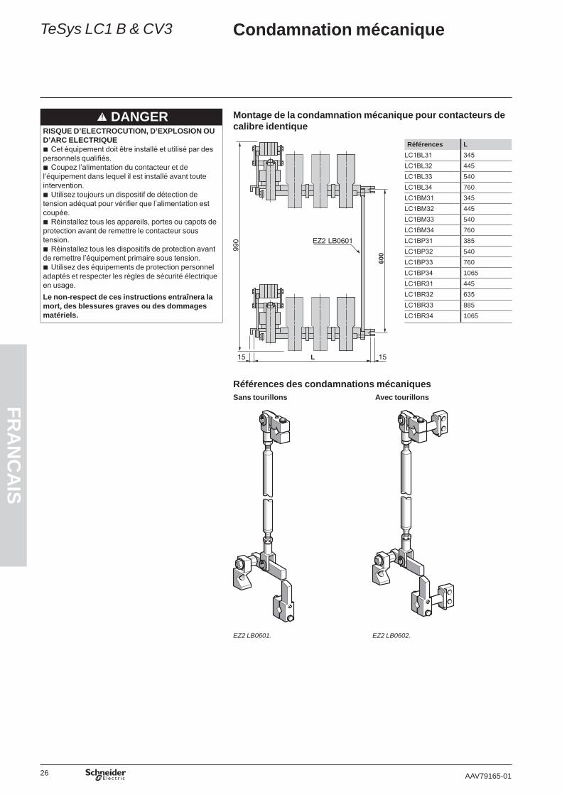
Condamnation mécanique
DANGER Montage de la condamnation mécanique pour contacteurs de calibre identiqueRISQUE D’ELECTROCUTION, D’EXPLOSION OU
D’ARC ELECTRIQUECet équipement doit être installé et utilisé par des
personnels qualifiés.Coupez l’alimentation du contacteur et de
l’équipement dans lequel il est installé avant toute intervention.
Utilisez toujours un dispositif de détection de tension adéquat pour vérifier que l’alimentation est coupée.
Réinstallez tous les appareils, portes ou capots de protection avant de remettre le contacteur sous tension.
Réinstallez tous les dispositifs de protection avant de remettre l’équipement primaire sous tension.
Utilisez des équipements de protection personnel adaptés et respecter les règles de sécurité électrique en usage.Le non-respect de ces instructions entraînera la mort, des blessures graves ou des dommages matériels.
b
b
b
b
b
b
600
L
Références L LC1BL31 345LC1BL32 445LC1BL33 540LC1BL34 760LC1BM31 345LC1BM32 445LC1BM33 540LC1BM34 760LC1BP31 385LC1BP32 540LC1BP33 760LC1BP34 1065LC1BR31 445LC1BR32 635LC1BR33 885LC1BR34 1065
Références des condamnations mécaniquesSans tourillons Avec tourillons
EZ2 LB0601. EZ2 LB0602.
TeSys LC1 B & CV3

27AAV79165-01
FRA
NC
AIS
Condamnation mécanique
Réglage de la condamnation mécanique
Contacteur supérieur
A =
(E–1
12) 4
88
E =
600
A
B
D
E
C
1 m
m
G
F
F
Contacteur inférieur
G Sens de rotation pour lever le loquet de condamnation mécaniqueF Barreau
Couper la tension du circuit de puissance.Vérifier l'absence de tension sur le circuit de puissance.Débloquer les écrous A et C.Fermer le contacteur inférieur électriquement ou mécaniquement. Tourner la tige B pour déplacer le loquet de condamnation E et l'amener à une distance de 1 mm du doigt de condamnation D.Bloquer ce réglage par les écrous A et C.Ouvrir le contacteur inférieur.Fermer le contacteur supérieur.Vérifier que le loquet de condamnation E ne frotte pas sur le doigt de condamnation D.
1.2.3.4.
5.6.7.8.
TeSys LC1 B & CV3
28 AAV79165-01
FRA
NC
AIS
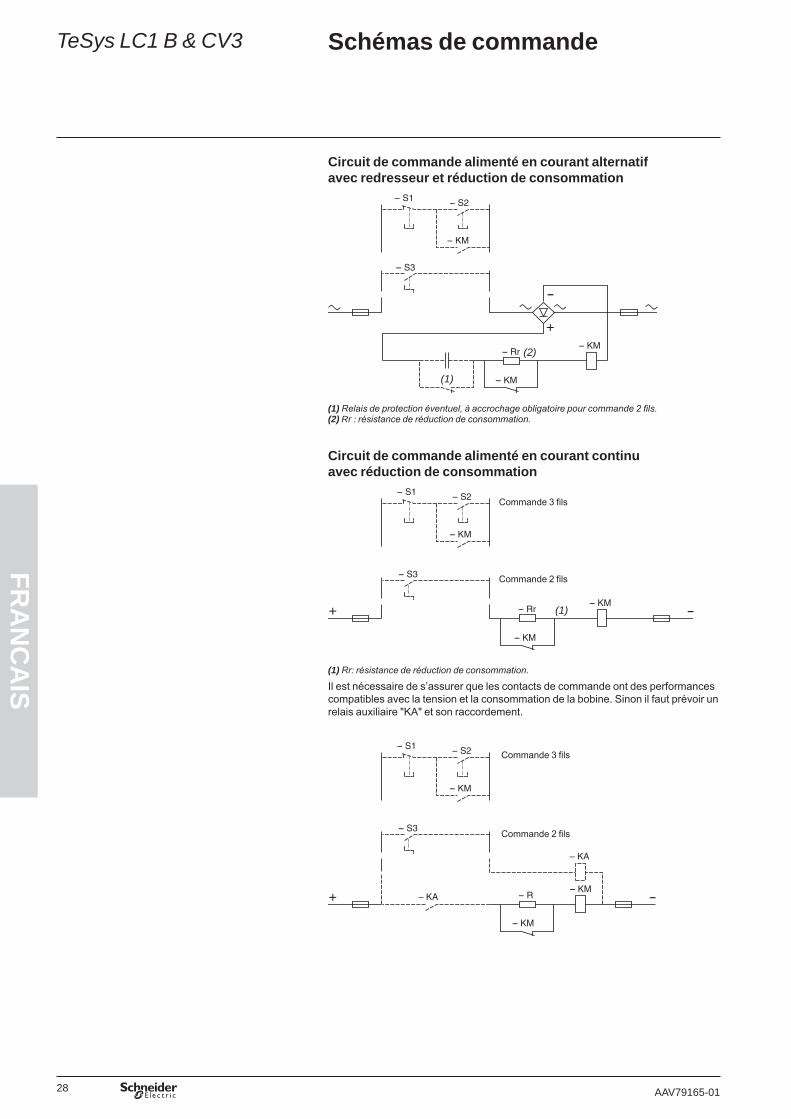
Schémas de commande
Circuit de commande alimenté en courant alternatif avec redresseur et réduction de consommation
(1)
(2)
(1) Relais de protection éventuel, à accrochage obligatoire pour commande 2 fils.(2) Rr : résistance de réduction de consommation.
Circuit de commande alimenté en courant continu avec réduction de consommation
(1)
(1) Rr: résistance de réduction de consommation.
Il est nécessaire de s’assurer que les contacts de commande ont des performances compatibles avec la tension et la consommation de la bobine. Sinon il faut prévoir un relais auxiliaire "KA" et son raccordement.
TeSys LC1 B & CV3
Commande 3 fils
Commande 2 fils
Commande 3 fils
Commande 2 fils

29AAV79165-01
FRA
NC
AIS
Guide de dépannage simplifiéTeSys LC1 B & CV3
DANGERRISQUE D’ELECTROCUTION, D’EXPLOSION OU D’ARC ELECTRIQUE
Cet équipement doit être installé et utilisé par des personnels qualifiés.Coupez l’alimentation du contacteur et de l’équipement dans lequel il est installé avant toute intervention.Utilisez toujours un dispositif de détection de tension adéquat pour vérifier que l’alimentation est coupée.Pour les vérifications sous tension du circuit de commande, prendre toutes les précautions nécessaires pour éviter les chocs électriques.Réinstallez tous les appareils, portes ou capots de protection, boîtiers de soufflage, pôles de soufflage avant de remettre le contacteur sous
tension.Réinstallez tous les dispositifs de protection avant de remettre l’équipement primaire sous tension.Utilisez des équipements de protection personnel adaptés et respecter les règles de sécurité électrique en usage.
Le non-respect de ces instructions entraînera la mort, des blessures graves ou des dommages matériels.
bbbbb
bb
Type de circuit de commande
Vérifications à effectuer Actions correctives
Le contacteur ne monte pasc ou a, avec ou sans réduction de consommation
Vérifier si la tension de commande du contacteur correspond à celle du contacteur.
Adapter la tension du circuit de commande ou le contacteur.
c ou a, avec réduction de consommation
Vérifier si la tension est présente aux bornes du circuit de commande du contacteur.
Dépanner le circuit de commande.
c ou a, avec ou sans réduction de consommation
Vérifier la tension de commande après le redresseur. La tension continue est presque égale à la tension alternative.
Changer le redresseur.
c ou a, avec réduction de consommation
Vérifier l’état et le réglage du contact de réduction de consommation.
Si les contacts sont trop usés, changer le ZC4GM2. Si un des contacts mobiles ne touche pas le contact fixe, refaire le réglage si possible, ou consulter nos services techniques.
c ou a, avec ou sans réduction de consommation
Vérifier qu’il y a continuité de la ou des bobines. Changer la bobine défectueuse.
c Vérifier que le fil ou le shunt de liaison des 2 bobines est présent et en bon état.
Changer ou remettre le fil ou le shunt correctement.
c ou a, avec ou sans réduction de consommation
Vérifier que le câblage est correct, fil à fil. Changer le fil défectueux.
Le contacteur ne reste pas ferméc ou a, avec ou sans réduction de consommation
Vérifier que le circuit d’alimentation de la commande a une puissance suffisante (au moins la puissance à l’appel du contacteur le plus puissant).
Augmenter la puissance du circuit de commande.
c ou a, avec ou sans réduction de consommation
Vérifier que la section des fils d’alimentation est suffisante, en particulier pour les tensions inférieures à 110 V.
Augmenter la section des fils pour adapter leur section au courant d’appel du contacteur (voir tableaux bobines page 32 à page 35).
c ou a, avec réduction de consommation
Vérifier que le contact de réduction est réglé correctement. Refaire le réglage si possible ou consulter nos services techniques.
c ou a, avec réduction de consommation
Vérifier la continuité du circuit de réduction en fermant mécaniquement les circuits fixe et mobile. L’impédance du circuit doit être égale à l’impédance de la bobine plus les résistances de réduction.
Changer l’élément défaillant (fil ou résistance).
c ou a, avec ou sans réduction de consommation
Vérifier qu’il n’y a pas de dur mécanique sur l’arbre du contacteur.
Chercher l’origine de la contrainte et éliminez-la.
c ou a, avec ou sans réduction de consommation (sauf c direct)
Vérifier que le circuit mobile ne frotte pas sur les supports butée.
Desserrer les 2 vis du circuit mobile, le recentrer et le descendre éventuellement pour qu’il ne frotte plus.
c ou a, avec réduction de consommation
Vérifier que la condamnation mécanique est bien réglée. Régler la condamnation mécanique.
Le contacteur retombe lentementc ou a, avec réduction de consommation
Vérifier que les faces des circuits sont propres. Nettoyer les faces polaires avec un chiffon sec ou légèrement imbibé de diluant.
c ou a, avec ou sans réduction de consommation
Vérifier qu’il y a encore un entrefer (différence entre les faces haute et basse et la face du milieu sur le circuit mobile pour des circuits feuilletés et rondelle amagnétique pour les circuits massifs).
Changer l’électro-aimant.
c ou a, avec ou sans réduction de consommation
Vérifier que la pression des pôles n’est pas trop faible. Régler la pression (éventuellement changer les ressorts si trop affaissés).
c ou a, avec ou sans réduction de consommation
Vérifier que l’écrasement des pôles n’est pas trop faible. Si l’écrasement est < 50 % de la valeur d’origine, changer les contacts du contacteur et rerégler les écrasements.Nota : ne jamais régler la valeur d’écrasement sur des contacts usagés.
c ou a, avec ou sans réduction de consommation
Vérifier que l’état et la tension du ressort de rappel sont corrects.
Régler ou changer le ressort de rappel. Le réglage se fait en fonction de la tension de montée.
Le contacteur ne retombe pasc ou a, avec ou sans réduction de consommation
Vérifier qu’il n’y a plus de tension de commande. Couper le circuit de commande.
c ou a, avec ou sans réduction de consommation
Vérifier qu’il n’y a pas de contacts soudés. 1. Couper le circuit de puissance.2. Essayer d’ouvrir le contacteur manuellement à l’aide d’un levier S’il est impossible d’ouvrir le contacteur manuellement, démonter les contacts et les remplacer par des contacts neufs (voir procédure page 30).

30 AAV79165-01
FRA
NC
AIS
Entretien
DANGERRISQUE D’ELECTROCUTION, D’EXPLOSION OU D’ARC ELECTRIQUE
Cet équipement doit être installé et utilisé par des personnels qualifiés.Coupez l’alimentation du contacteur et de l’équipement dans lequel il est installé
avant toute intervention.Utilisez toujours un dispositif de détection de tension adéquat pour vérifier que
l’alimentation est coupée.Réinstallez tous les appareils, portes ou capots de protection avant de remettre
le contacteur sous tension.Réinstallez tous les dispositifs de protection avant de remettre l’équipement
primaire sous tension.Utilisez des équipements de protection personnel adaptés et respecter les
règles de sécurité électrique en usage.Le non-respect de ces instructions entraînera la mort, des blessures graves ou des dommages matériels.
bb
b
b
b
b
Ces contacteurs ne nécessitent aucun entretien particulier.Les contacts ne doivent jamais être limés ni graissés, seul un léger nettoyage au papier de verre est possible.Les contacts ayant effectués de nombreuses coupures peuvent donner une impression d’usure. Seule la vérification de la cote d’écrasement permet d’évaluer le degré d’usure (voir procédure ci-dessous).
Circuitfixe
Bobine
Circuit mobile
Ressort de rappel
Procédure de vérification de l’écrasement des contactsL’écrasement est à vérifier pour chaque jeu de contact un par un.
Couper l’alimentation de la puissance.Faire se toucher les pastilles fixes et mobiles d’un jeu de contact en fermant l’électro-aimant et relever la cote "e" entre circuit fixes et mobiles en haut de l’électro-aimant (voir page 31). Le contact entre les deux pastilles peut être vérifié :
si possible électriquement à l’ohmètre ou avec une lampe témoin (chercher juste le point où les contacts se touchent)
ou mécaniquement avec une feuille de papier fin entre les contacts (bloquer le papier sans l’écraser).
1.2.
b
b
Important :Réglage course d’appel (E) et d’écrasement (e). Si la cote d’écrasement "e" est > 50 % de la valeur d’origine ne jamais procéder à
un nouveau réglage.Si la cote d’écrasement "e" se trouve y 30 et 50 % de la cote initiale d’écrasement sur un jeu de contacts, changer systématiquement tous les jeux de contacts du contacteur et procéder au réglage (voir procédure ci-dessous).La cote d’écrasement "e" ne peut être réglée que sur des contacts neufs.
Procédure de changement et de réglage des contactsContactfixe
Contact mobile
Réglage coted’écrasement
Réglage forced’applicationRessort
de pôle
Démonter les anciens contacts.Nettoyer par grattage les parois intérieures des boîtiers de soufflage.Remonter tous les nouveaux jeux de contacts en les serrant à 21 Nm.Desserer tous les contre-écrous sur les vis de réglage HC 8 x 45.Serrer toutes les vis HC 8 x 45 pour éloigner les contacts mobiles des contacts fixes. Fermer l’électro-aimant mécaniquement avec, entre le circuit fixe et le circuit mobile, un cale de la valeur de l’écrasement désiré + 0,5 mm (par exemple pour une cote d’écrasement de 10 mm mettre une cale de 10,5 mm au niveau des arrêtes supérieures des circuits fixes et mobiles).Desserer la vis du premier jeu de contacts jusqu’à ce que les deux contacts se touchent puis resserrer d’1/8 de tour et bloquer le contre écrou.Procéder de la même façon pour tous les jeux de contacts.Fermer électriquement, ou mécaniquement l’électro-aimant.Vérifier la pression de chaque jeu de contacts : b soit en tirant directement au centre de la pastille du doigt mobile avec un peson b soit en tirant avec un levier W80751732 et un peson sur la main de fer pour les pôles PA2 ou un levier W80765164 et d’un peson sur le support contact mobiles pour les pôles PA1, PA3 et PA5. (Dans le cas où l’on utilise un levier, tenir compte du coefficient multiplicateur de celui-ci dans la mesure)Vérifier le serrage des contres-écrous de réglage.
1.2.3.4.5.
6.
7.
8.9.10.
11.
Réglage de la force F de contact des pôles.
TeSys LC1 B & CV3

31AAV79165-01
FRA
NC
AIS
Caractéristiques de réglage
Caractéristiques de réglage des contacteurs CV3 (calibres L à R et LC1 B)Electro-aimantElectro-aimant EB5 KB50 Réglage course d'appel (E) et d'écrasement (e)
Circuitfixe
Bobine
Circuit mobile
Ressort de rappel
PôlesPôle complet Pôle à fermeture
Contactfixe
Contact mobile
Réglage coted’écrasement
Réglage forced’applicationRessort
de pôle
Caractéristiques de réglage en c ou a avec réduction de consommation (et redresseur en a)Calibre du contacteur CV3 ou LC1 B L M P R
Electro-aimant EB5 KB50 EB5 KB50 EB5 KB50 EB5 KB50Course d’appel (E) mm 30 ±2 30 ±2 30 ±2 30 ±2Course d’écrasement (e) mm 10 ±0,5 10 ±0,5 10 ±0,5 10 ±0,5
Contact de réduction Course d'ouverture (e) mm 8-1 +2,5 8-1 +2,5 8-1 +2,5 8-1 +2,5
Bobine WB1 KBppp WB1 KBppp WB1 KBppp WB1 KBppp
Tension d’enclenchement V 0,73 ±0,02 Uc 0,73 ±0,02 Uc 0,73 ±0,02 Uc 0,73 ±0,02 UcTension de retombée V 0,25…0,5 Uc 0,25…0,5 Uc 0,25…0,5 Uc 0,25…0,5 Uc
Pôle à fermetureRéglage de la force (F) d’application au contact par pôle suivant la composition du contacteur
1 pôle daN 30 ±3 30 ±3 30 ±3 (1) 30 ±3 (2)2 pôles daN 30 ±3 30 ±3 30 ±3 (1) 30 ±3 (2)3 pôles daN 30 ±3 30 ±3 30 ±3 (1) 30 ±3 (2)4 pôles daN 30 ±3 30 ±3 30 ±3 (1) 30 ±3 (2)
(1) Chaque pôle comporte 2 contacts ; la force est à répartir par moitié sur chacun des contacts.(2) Chaque pôle comporte 3 contacts ; la force est à répartir par tiers sur chacun des contacts.
TeSys LC1 B & CV3

32 AAV79165-01
FRA
NC
AIS
Bobines et éléments à associerPour contacteurs unipolaires
TeSys LC1 B & CV3
RéférencesLes mêmes bobines sont utilisées pour la commande des contacteurs en c ou a.
En courant continu, il convient d’associer à la bobine :1 dispositif de réduction de consommation (résistances + 1 ou 2 contact(s)
auxiliaire(s) ou 1 contacteur).En courant alternatif 50 à 400 Hz, il convient d’associer à la bobine : 1 redresseur individuel (à raccorder)1 dispositif de réduction de consommation (résistances + contact(s) auxiliaire(s)
ou 1 contacteur) câblé côté courant redressé.
bv
bvv
WB1 KBppp
Plage d’utilisation mini-maxi (1)
Bobine Réduction de consommation Redresseur (en a seulement)
Bobine Masse
Continu Alternatif Résistance à 20 °C ±10 %
I appel ±10 % à Un maxi
Résistance Contact Référence RéférenceRéférenceunitaire
Résistance totale
Qté Référence
V V W A W kg47-51 – 5,1 10,3 DR2 SC0270 270 1 ZC4 GM2 – WB1 KB155 1,12052-56 – 5,9 9,5 DR2 SC0330 330 1 ZC4 GM2 – WB1 KB132 1,12057-64 – 7,3 8,9 DR2 SC0390 390 1 ZC4 GM2 – WB1 KB123 1,12065-68 – 9,5 7,1 DR2 SC0560 560 1 ZC4 GM2 – WB1 KB133 1,12069-79 – 11,6 6,9 DR2 SC0680 680 1 ZC4 GM2 – WB1 KB121 1,12080-87 – 16,2 5,3 DR2 SC0820 820 1 ZC4 GM2 – WB1 KB130 1,12088-94 – 19,9 4,7 DR2 SC1000 1000 1 ZC4 GM2 – WB1 KB140 1,12095-108 110-125 25,5 4,3 DR2 SC1200 1200 1 ZC4 GM2 DR5 TE1U WB1 KB134 1,120109-136 126-155 33,1 4,2 DR2 SC1800 1800 1 ZC4 GM2 DR5 TE1U WB1 KB124 1,120137-151 156-173 50,9 3 DR2 SC2700 2700 2 ZC4 GM2 DR5 TE1U WB1 KB122 1,120152-166 174-191 61,36 2,7 DR2 SC3300 3300 2 ZC4 GM2 DR5 TE1U WB1 KB135 1,120167-189 192-216 78,4 2,4 DR2 SC3900 3900 2 ZC4 GM2 DR5 TE1U WB1 KB136 1,120190-221 217-256 94,8 2,3 DR2 SC4700 4700 2 ZC4 GM2 DR5 TE1U WB1 KB139 1,120222-243 257-280 123,9 1,9 DR2 SC6800 6800 1 LC1 DT20 LDS135 DR5 TE1U WB1 KB125 1,120244-267 281-307 159,9 1,7 DR2 SC8200 4700
+ 33001 LC1 DT20 LDS135 DR5 TE1S WB1 KB137 1,120
268-318 308-365 199,6 1,6 DR2 SC1001 5600 + 4700
1 LC1 DT20 UDS135 DR5 TE1S WB1 KB126 1,120
319-405 366-463 247,4 1,6 DR2 SC1201 6800 + 5600
1 LC1 DT20 TDS135 DR5 TE1S WB1 KB138 1,120
406-446 464-500 382 1,1 (2) DR2 SC1001 20 000 1 LC1 DT20 VDS135 DR5 TE1S WB1 KB127 1,120447-500 – 506,7 1 (3) DR2 SC1201 24 000 1 LC1 DT20 RDS135 – WB1 KB128 1,120(1) Pour les tensions d’alimentation inférieures à 110 V, prendre garde aux chutes de tension provoquées par le courant d’appel.(2) 2 résistances en série : 2 x 10 000 Ohm.(3) 2 résistances en série : 2 x 12 000 Ohm.
SpécificationsConsommation moyenne de la bobine (faible consommation au maintien) :courant continu : appel 380…520 W, maintien 0,15…0,20 Wcourant alternatif (avec redresseur) : appel 450…620 VA, maintien 0,15…0,20 VAConstante de temps au maintien 25 msConsommation de la résistance de réduction : 7…10 WCycles de manœuvres/heure à q y 55 °C : y 120Durabilité mécanique à Uc : 1,2 million de cycles de manœuvresEn alternatif : bonne tenue aux chutes de tension à l’appel, non susceptibilité aux
micro-coupures, harmoniques réseau : rang y 7.
bvvbbbbb

33AAV79165-01
FRA
NC
AIS
Bobines et éléments à associerPour contacteurs bipolaires
RéférencesLes mêmes bobines sont utilisées pour la commande des contacteurs en c ou a.
En courant continu, il convient d’associer à la bobine :1 dispositif de réduction de consommation (résistances + 1 ou 2 contact(s)
auxiliaire(s) ou 1 contacteur).En courant alternatif 50 à 400 Hz, il convient d’associer à la bobine : 1 redresseur individuel (à raccorder)1 dispositif de réduction de consommation (résistances + contact(s) auxiliaire(s)
ou 1 contacteur) câblé côté courant redressé.
bv
bvv
WB1 KBppp
Plage d’utilisation mini-maxi (1)
Bobine Réduction de consommation Redresseur (en a seulement)
Bobine Masse
Continu Alternatif Résistance à 20 °C ± 10 %
I appel ± 10 % à Un maxi
Résistance (2 en série) Contact Référence RéférenceRéférenceunitaire
Résistance totale
Qté Référence
V V W A W kg48-51 – 3,22 15,8 DR2 SC0068 2 x 68 1 ZC4 GM2 – WB1 KB141 1,12052-56 – 4,04 13,8 DR2 SC0082
DR2 SC010082 + 100 1 ZC4 GM2 – WB1 KB142 1,120
57-62 – 4,96 12,5 DR2 SC0100 DR2 SC0120
100 + 120 1 ZC4 GM2 – WB1 KB155 1,120
63-68 – 5,86 11,6 DR2 SC0120 2 x 120 1 ZC4 GM2 – WB1 KB132 1,12069-79 – 7,2 11 DR2 SC0150 2 x 150 1 ZC4 GM2 – WB1 KB123 1,12080-85 – 9,6 8,8 DR2 SC0180
DR2 SC0220180 + 220 1 ZC4 GM2 – WB1 KB133 1,120
86-98 99-113 11,4 8,6 DR2 SC0220 DR2 SC0270
220 + 270 1 ZC4 GM2 – WB1 KB121 1,120
99-108 114-125 16,3 6,6 DR2 SC0330 2 x 330 1 ZC4 GM2 DR5 TE1U WB1 KB130 1,120109-119 126-136 19,7 6 DR2 SC0390 2 x 390 1 ZC4 GM2 DR5 TE1U WB1 KB140 1,120120-136 137-156 25,2 5,4 DR2 SC0470 2 x 470 2 ZC4 GM2 DR5 TE1U WB1 KB134 1,120137-173 157-196 32,5 5,3 DR2 SC0680 2 x 680 2 ZC4 GM2 DR5 TE1U WB1 KB124 1,120174-191 197-216 49,7 3,8 DR2 SC1000 2 x 1000 2 ZC4 GM2 DR5 TE1U WB1 KB122 1,120192-210 217-238 61 3,4 DR2 SC1200 2 x 1200 2 ZC4 GM2 DR5 TE1U WB1 KB135 1,120211-238 239-272 77,2 3 DR2 SC1500
DR2 SC18001500 + 1800 2 ZC4 GM2 DR5 TE1U WB1 KB136 1,120
239-279 273-318 94 3 DR2 SC1800 DR2 SC2200
1800 + 2200 1 LP1 DT20 LDS135 DR5 TE1S WB1 KB139 1,120
280-310 319-359 128 2,4 DR2 SC2700 2 x 2700 1 LP1 DT20 UDS135 DR5 TE1S WB1 KB125 1,120311-341 360-387 160 2,1 DR2 SC3300 2 x 3300 1 LP1 DT20 TDS135 DR5 TE1S WB1 KB137 1,120342-399 388-452 197 2 DR2 SC3900 2 x 3900 1 LP1 DT20 TDS135 DR5 TE1S WB1 KB126 1,120400-500 453-500 257 1,9 DR2 SC4700
DR2 SC56004700 + 5600
1 LP1 DT20 VDS135 DR5 TE1S WB1 KB138 1,120
(1) Pour les tensions d’alimentation inférieures à 110 V, prendre garde aux chutes de tension provoquées par le courant d’appel.
SpécificationsConsommation moyenne de la bobine (faible consommation au maintien) :courant continu : appel 600…800 W, maintien 0,35…0,5 Wcourant alternatif (avec redresseur) : appel 720…1000 VA, maintien 0,35…0,5 VAConstante de temps au maintien 25 msConsommation de la résistance de réduction : 15…20 WCycles de manœuvres/heure à q y 55 °C : y 120Durabilité mécanique à Uc : 1,2 million de cycles de manœuvresEn alternatif : bonne tenue aux chutes de tension à l’appel, non susceptibilité aux
micro-coupures, harmoniques réseau : rang y 7.
bvvbbbbb
TeSys LC1 B & CV3

34 AAV79165-01
FRA
NC
AIS
Bobines et éléments à associerPour contacteurs tripolaires
RéférencesLes mêmes bobines sont utilisées pour la commande des contacteurs en c ou a.
En courant continu, il convient d’associer à la bobine :1 dispositif de réduction de consommation (résistances + 1 ou 2 contact(s)
auxiliaire(s) ou 1 contacteur).En courant alternatif 50 à 400 Hz, il convient d’associer à la bobine : 1 redresseur individuel (à raccorder)1 dispositif de réduction de consommation (résistances + contact(s) auxiliaire(s)
ou 1 contacteur) câblé côté courant redressé.
bv
bvv
WB1 KBppp
Plage d’utilisation mini-maxi (1)
Bobine Réduction de consommation Redresseur (en a seulement)
Bobine Masse
Continu Alternatif Résistance à 20 °C ± 10 %
I appel ± 10 % à Un maxi
Résistance (2 en parallèle ou en série)
Contact Référence Référence
Référenceunitaire
Résistance totale
Qté Référence
V V W A W kg47-50 – 1,85 27 DR2 SC0150 2 x 150// 1 ZC4 GM2 – WB1 KB154 1,12051-55 – 2,35 23,5 DR2 SC0180 2 x 180// 1 ZC4 GM2 – WB1 KB153 1,12056-60 – 3,22 18,5 DR2 SC0220 2 x 220// 1 ZC4 GM2 – WB1 KB141 1,12061-66 – 4,04 16 DR2 SC0270 2 x 270// 1 ZC4 GM2 – WB1 KB142 1,12067-72 – 4,96 14,5 DR2 SC0330 2 x 330// 1 ZC4 GM2 – WB1 KB155 1,12073-79 – 5,86 13,5 DR2 SC0100 2 x 100 1 ZC4 GM2 – WB1 KB132 1,12080-92 – 7,2 12,8 DR2 SC0120 2 x 120 1 ZC4 GM2 – WB1 KB123 1,12093-98 108-113 9,6 10,2 DR2 SC0150
DR2 SC0180150 + 180 1 ZC4 GM2 DR5 TE1U WB1 KB133 1,120
99-114 114-132 11,4 10 DR2 SC0180 DR2 SC0220
180 + 220 1 ZC4 GM2 DR5 TE1U WB1 KB121 1,120
115-126 133-145 16,3 7,7 DR2 SC0270 2 x 270 2 ZC4 GM2 DR5 TE1U WB1 KB130 1,120127-139 146-160 11,7 7 DR2 SC0330 2 x 330 2 ZC4 GM2 DR5 TE1U WB1 KB140 1,120140-159 161-181 25,2 6,3 DR2 SC0390
DR2 SC0470390 + 470 2 ZC4 GM2 DR5 TE1U WB1 KB134 1,120
160-201 182-228 32,2 6,2 DR2 SC0560 2 x 560 2 ZC4 GM2 DR5 TE1U WB1 KB124 1,120202-222 229-255 49,7 4,5 DR2 SC0820 2 x 820 2 ZC4 GM2 DR5 TE1U WB1 KB122 1,120223-246 256-282 61 4 DR2 SC1000 2 x 1000 1 LC1 DT20 LDS135 DR5 TE1S WB1 KB135 1,120247-277 283-316 77,2 3,6 DR2 SC1200 2 x 1200 1 LC1 DT20 LDS135 DR5 TE1S WB1 KB136 1,120278-327 317-372 94 3,5 DR2 SC1500 2 x 1500 1 LC1 DT20 UDS135 DR5 TE1S WB1 KB139 1,120328-360 373-408 128 2,8 DR2 SC1500 3 x 1500 1 LC1 DT20 TDS135 DR5 TE1S WB1 KB125 1,120361-399 409-452 160 2,5 DR2 SC1800 3 x 1800 1 LC1 DT20 VDS135 DR5 TE1S WB1 KB137 1,120400-469 453-500 197 2,4 DR2 SC2200 3 x 2200 1 LC1 DT20 VDS135 DR5 TE1S WB1 KB126 1,120470-500 – 257 1,9 DR2 SC2700 3 x 2700 1 LC1 DT20 RDS135 – WB1 KB138 1,120(1) Pour les tensions d’alimentation inférieures à 110 V, prendre garde aux chutes de tension provoquées par le courant d’appel.
SpécificationsConsommation moyenne de la bobine (faible consommation au maintien) :courant continu : appel 900…1100 W, maintien 0,7…1 Wcourant alternatif (avec redresseur) : appel 1100…1300 VA, maintien 0,7…1 VAConstante de temps au maintien 25 msConsommation de la résistance de réduction : 24…30 WCycles de manœuvres/heure à q y 55 °C : y 120Durabilité mécanique à Uc : 1,2 million de cycles de manœuvresEn alternatif : bonne tenue aux chutes de tension à l’appel, non susceptibilité aux
micro-coupures, harmoniques réseau : rang y 7.
bvvbbbbb
TeSys LC1 B & CV3

35AAV79165-01
FRA
NC
AIS
Bobines et éléments à associerPour contacteurs tétrapolaires
RéférencesLes mêmes bobines sont utilisées pour la commande des contacteurs en c ou a.
En courant continu, il convient d’associer à la bobine :1 dispositif de réduction de consommation (résistances + 1 ou 2 contact(s)
auxiliaire(s) ou 1 contacteur).En courant alternatif 50 à 400 Hz, il convient d’associer à la bobine : 1 redresseur individuel (à raccorder)1 dispositif de réduction de consommation (résistances + contact(s) auxiliaire(s)
ou 1 contacteur) câblé côté courant redressé.
bv
bvv
WB1 KBppp
Plage d’utilisation mini-maxi (1)
Bobine Réduction de consommation Redresseur (en a seulement)
Bobine Masse
Continu Alternatif Résistance à 20 °C ± 10 %
I appel ± 10 % à Un maxi
Résistance (3 en série) Contact Référence RéférenceRéférenceunitaire
Résistance totale
Qté Référence
V V W A W kg57-61 – 2,35 26 DR2 SC0027 3 x 27 1 ZC4 GM2 – WB1 KB153 1,12062-67 – 3,22 21 DR2 SC0033 3 x 33 1 ZC4 GM2 – WB1 KB141 1,12068-73 – 4,04 18 DR2 SC0039 3 x 39 1 ZC4 GM2 – WB1 KB142 1,12074-81 – 4,96 16,3 DR2 SC0047 3 x 47 1 ZC4 GM2 – WB1 KB155 1,12082-89 – 5,86 15 DR2 SC0056 3 x 56 1 ZC4 GM2 – WB1 KB132 1,12090-102 105-119 7,2 14 DR2 SC0068 3 x 68 1 ZC4 GM2 DR5 TE1U WB1 KB123 1,120103-111 120-128 9,6 11,5 DR2 SC0100 3 x 100 2 ZC4 GM2 DR5 TE1U WB1 KB133 1,120112-129 129-148 11,4 11,3 DR2 SC0100 3 x 100 2 ZC4 GM2 DR5 TE1U WB1 KB121 1,120130-143 149-163 16,3 8,7 DR2 SC0150 3 x 150 2 ZC4 GM2 DR5 TE1U WB1 KB130 1,120144-157 164-179 19,7 8 DR2 SC0180 3 x 180 2 ZC4 GM2 DR5 TE1U WB1 KB140 1,120158-180 180-204 25,2 7,1 DR2 SC0220 3 x 220 2 ZC4 GM2 DR5 TE1U WB1 KB134 1,120181-226 205-259 32,5 6,9 DR2 SC0330 3 x 330 2 ZC4 GM2 DR5 TE1U WB1 KB124 1,120227-251 260-288 49,7 5 DR2 SC0470 3 x 470 1 LC1 DT20 LDS135 DR5 TE1S WB1 KB122 1,120252-278 289-317 61 4,5 DR2 SC0560 3 x 560 1 LC1 DT20 UDS135 DR5 TE1S WB1 KB135 1,120279-313 318-356 77,2 4 DR2 SC0680 3 x 680 1 LC1 DT20 UDS135 DR5 TE1S WB1 KB136 1,120314-368 357-418 94 3,9 DR2 SC0820 3 x 820 1 LC1 DT20 TDS135 DR5 TE1S WB1 KB139 1,120369-408 419-462 128 3,2 DR2 SC1200 3 x 1200 1 LC1 DT20 VDS135 DR5 TE1S WB1 KB125 1,120409-448 463-500 160 2,8 DR2 SC1500 3 x 1500 1 LC1 DT20 VDS135 DR5 TE1S WB1 KB137 1,120449-500 – 197 2,5 DR2 SC1800 3 x 1800 1 LC1 DT20 RDS135 – WB1 KB126 1,120(1) Pour les tensions d’alimentation inférieures à 110 V, prendre garde aux chutes de tension provoquées par le courant d’appel.
SpécificationsConsommation moyenne de la bobine (faible consommation au maintien) :courant continu : appel 1100…1400 W, maintien 1,2…1,6 Wcourant alternatif (avec redresseur) : appel 1300…1600 VA, maintien 1,2…1,6 VAConstante de temps au maintien 25 msConsommation de la résistance de réduction : 35…45 WCycles de manœuvres/heure à q y 55 °C : y 120Durabilité mécanique à Uc : 1,2 million de cycles de manœuvresEn alternatif : bonne tenue aux chutes de tension à l’appel, non susceptibilité aux
micro-coupures, harmoniques réseau : rang y 7.
bvvbbbbb
TeSys LC1 B & CV3

36 AAV79165-01
FRA
NC
AIS
Pièces de rechange
Références et caractéristiques des pièces de rechange Electro-aimant
Référence EB5KB50Masse (kg) 10,600Dimensions
265
BobineRéférence WB1KBppp (voir références complètes page 32 à page 35)Masse (kg) 1,120Dimensions
48
RedresseurRéférence DR5TE1p (voir références complètes page 32 à page 35)Masse (kg) 0,040Dimensions
60
60
22
C
C
RésistanceRéférence DR2SCppp (voir références complètes page 32 à page 35)Masse (kg) 0,030Dimensions
Contact auxiliaire Contact F Contact ORéférence ZC4GM1 ZC4GM2 Masse (kg) 0,030 0,030Dimensions
78 78
TeSys LC1 B & CV3

37AAV79165-01
FRA
NC
AIS
Pièces de rechange
Références des pièces de rechange par calibre de contacteurPièces de rechange Calibre du contacteur
L M P RJeu de contacts (par pôle) 1 x PA1LB80 1 x PA1LB80 2 x PA1LB80 3 x PA1LB80Corne de soufflage (par pôle) 1 x PA1LB89 1 x PA1LB89 2 x PA1LB89 3 x PA1LB89Boîtier de soufflage sans bobine 1 x PA1LB50 1 x PA1LB50 1 x PA1PB50 1 x PA1RB50Boîtier de soufflage avec bobine 1 x PA1LB52 1 x PA1LB52 1 x PA1PB52 1 x PA1RB52Pôle complet 1 x PA2LB00 1 x PA2MB00 1 x PA2PB00 1 x PA2RB00
CaractéristiquesContacts Corne de soufflage
Référence PA1LB80 PA1LB89Masse (kg) 0,420 0,120Dimensions
35
74 90
Boîtier de soufflage sans bobineRéférence PA1LB50 PA1BP50 PA1RB50Masse (kg) 3,7 6,2 8,5Dimensions
225 225 225
Boîtier de soufflage avec bobineRéférence PA1LB52 PA1PB52 PA1RB52Masse (kg) 4,8 8,5 12,2Dimensions
225 225 225
Pôle completRéférence PA2LB00 PA2MB00Masse (kg) 11,0 12,0Dimensions
16
50
20
63
Pôle completRéférence PA2PB00 PA2RB00Masse (kg) 22,0 32,0Dimensions
20
100
25
125
TeSys LC1 B & CV3

38 AAV79165-01
FRA
NC
AIS
Notes

39AAV79165-01
FRA
NC
AIS
Notes

40 AAV79165-01
FRA
NC
AIS
Notes


Schneider Electric Industries SAS89, boulevard Franklin RooseveltF - 92505 Rueil-Malmaison Cedex (France)Tel : +33 (0)1 41 29 85 00
http://www.schneider-electric.com
As standards, specifications, designs and dimensions develop from time to time, always ask for confirmation of the information given in this publication.En raison de l’évolution des normes et du matériel, les caractéristiques indiquées par les textes et les images de ce document ne nous engagent qu’après confirmation par nos services.
This document has been printed on ecological paper. Ce document a été imprimé sur du papier écologique.
Production / Création, réalisation : Schneider ElectricPictures / Photos : Schneider ElectricPrinted / Impression : ©
200
8 - S
chne
ider
Ele
ctric
- A
ll rig
hts
rese
rved
/ To
us d
roits
rése
rvés
06-2008AAV79165-01