instruction manual - pneumercatorpneumercator.com/docs/tech/manuals/lc100x instruction...
TRANSCRIPT

AUDIBLE ALARM CONTROLS PNEUMERCATORLiquid Level Control Systems
INSTRUCTION MANUAL
Revised: July 2, 2017
LC1000 SERIES INTRINSICALLY SAFE
ALARM CONSOLE
© COPYRIGHT 2017 PNEUMERCATOR CO., INC. 1785 EXPRESSWAY DRIVE NORTH
HAUPPAUGE, NY 11788
(631) 293-8450 Phone (631) 293-8533 Fax
(800) 209-7858 Support www.pneumercator.com
LC100x Instruction Manual - 2017-07-02.docx
DRAWING NO. 20000 REV. A

LC1000 INSTRUCTION MANUAL TABLE OF CONTENTS
TABLE OF CONTENTSPage
SAFETY INFORMATION ........................................................................................ 5
Section 1 PRODUCT DESCRIPTION ..................................................................................... x 1.1 General System Overview ...................................................................................... 6 1.2 Control Console Description ................................................................................... 7 1.3 Liquid Sensor Description ..................................................................................... 10
Section 2 INSTALLATION DETAILS ...................................................................................... x
2.1 Installation Checklist ............................................................................................. 13 2.2 Control Console Installation .................................................................................. 14 2.3 Leak Sensor Installation – Steel Tanks ................................................................. 16 2.4 Leak Sensor Installation – Piping Sumps and Dispenser Pans, Vaulted Tank ..... 17 2.5 Leak Sensor Installation – Fiberglass Underground Tanks .................................. 18 2.6 Other Dry Contact Float Switches ......................................................................... 19
Section 3 WIRING INSTALLATION AND DIAGRAMS ........................................................... x
3.1 PC Board Setup and Layout ................................................................................. 20 3.2 System Wiring ....................................................................................................... 23 3.3 Sensor Map/System Setup ................................................................................... 27 3.4 Installation as a Remote Alarm Panel ................................................................... 27
Section 4 OPERATION ........................................................................................................... x
4.1 General ................................................................................................................. 28 4.2 Horn Control .......................................................................................................... 28
Section 5 TROUBLESHOOTING ............................................................................................ x
5.1 General ................................................................................................................. 29 5.2 Spare Parts List .................................................................................................... 29
Section 6 MAINTENANCE/TESTING ..................................................................................... x
6.1 Console ................................................................................................................. 30 6.2 Sensors ................................................................................................................. 30

LC1000 INSTRUCTION MANUAL SAFETY
PAGE 5
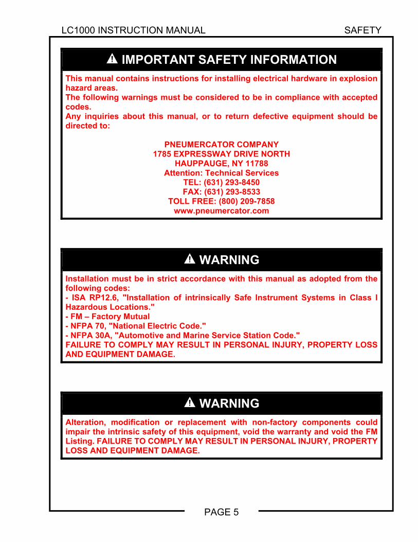
IMPORTANT SAFETY INFORMATION
This manual contains instructions for installing electrical hardware in explosion hazard areas. The following warnings must be considered to be in compliance with accepted codes. Any inquiries about this manual, or to return defective equipment should be directed to:
PNEUMERCATOR COMPANY 1785 EXPRESSWAY DRIVE NORTH
HAUPPAUGE, NY 11788 Attention: Technical Services
TEL: (631) 293-8450 FAX: (631) 293-8533
TOLL FREE: (800) 209-7858 www.pneumercator.com
WARNING
Installation must be in strict accordance with this manual as adopted from the following codes: - ISA RP12.6, "Installation of intrinsically Safe Instrument Systems in Class I Hazardous Locations." - FM – Factory Mutual - NFPA 70, "National Electric Code." - NFPA 30A, "Automotive and Marine Service Station Code." FAILURE TO COMPLY MAY RESULT IN PERSONAL INJURY, PROPERTY LOSS AND EQUIPMENT DAMAGE.
WARNING
Alteration, modification or replacement with non-factory components could impair the intrinsic safety of this equipment, void the warranty and void the FM Listing. FAILURE TO COMPLY MAY RESULT IN PERSONAL INJURY, PROPERTY LOSS AND EQUIPMENT DAMAGE.

LC1000 INSTRUCTION MANUAL PRODUCT DESCRIPTION
PAGE 6
SECTION 1 – PRODUCT DESCRIPTION 1.1 GENERAL SYSTEM OVERVIEW The basic function of the Model LC1000 Alarm console is to provide both audible and visual warning alarms at the occurrence of high, low, or leak conditions: typically via float switches, or any tank mounted sensing device that transmits an alarm condition by opening or closing dry switch contacts. The LC1000 may also be used as a non-intrinsically safe remote alarm panel for any system that provides a dry contact relay output to represent a specific set of conditions. The console is powered by 120 VAC and provides 1 to 4 input channels each with a corresponding light. Each input consists of a pair of intrinsically safe terminals for wiring to field mounted switches. The intrinsically safe inputs allow mounting the switches in explosion hazard environments without requiring additional protective barrier components in the wiring runs. For every input, there is a single dry contact relay output that can be used to signal a remote alarm device or control an external electrical device, such as a solenoid valve, up to 3A @ 120 VAC.
Figure 1-1 - LC1000 Series Overview
DRAWING NO. 20058 REV. A
RESET TEST
AC POWER
LLIFREVOKAEL
LIQUID STORAGE TANK OVERFILL/LEAK ALARM SYSTEM OVERVIE W
LC1002 CONSO LE(MOUNT OUTSIDEHAZARDOUS AREA )
90% CAPACITYTYPICAL
LEAK SENSOR
OVERFILLLEVELSWITCH
TESTRESET
RELAYOUTPUTS
HGIHPMUSKNAT
KAELKAEL
FIBERGLASS STORAGE TANK OVERFILL/LEAK ALARM SYSTEM OVERVIE W
HIGH LEVEL SWITCH
TYPICAL DOUBLE WALL TAN K(OR SECONDARY
CONTAINMENT )
90% CAPACITYTYPICAL
TYPICAL FIBERGLASSDOUBLE WALL TANK
RELAY OUTPU T
LIQUID FILLED RESERVOIRLEAK SENSO R
PIPING SUM PLEAK SENSO R
RE
LAY
OU
TP
UT
S
AC POWER
LC1003 CONSOLE(MOUNT OUTSIDE
HAZARDOUS AREA )

LC1000 INSTRUCTION MANUAL PRODUCT DESCRIPTION
PAGE 7
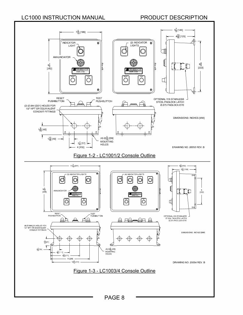
1.2 CONTROL CONSOLE DESCRIPTION The console is housed in a NEMA 4X (weather tight/corrosion resistant) FRP (fiberglass reinforced plastic) enclosure for mounting in the non-hazardous area. Each unit operates on 120 VAC power and provides from one (1) to four (4) intrinsically safe alarm channels for monitoring up to four independent sensing points. The electrical energy output at each channel is 12 VDC at 15 mADC maximum, and is zener barrier protected. Bright red alarm LEDs, one for each channel, and a horn are mounted to the enclosure cover. Each alarm channel is equipped with a 1 Form C output relay, totally isolated from the sensor inputs, rated for 3A@120VAC, for controlling external devices such as pumps (indirectly), valves or remote alarm annunciators. All field wiring is made through pressure-type terminal blocks enclosed under metal barriers to separate the power from the intrinsically safe wiring. Figures 1-2 and 1-3 illustrate the standard LC1000 outline, mounting flange locations, and dimensions. The console should be located in an area that is easily accessible to the personnel responsible for operation and maintenance of the system. Use only dedicated conduit entries for their designated purpose as specified in Figure 1-4. Metal conduiting is recommended and may be required by local codes. All outdoor conduits must be watertight.
WARNING
Installation MUST be done by qualified personnel familiar with local wiring codes and explosion hazard electrical safety practices. FAILURE TO COMPLY MAY RESULT IN PERSONAL INJURY, PROPERTY LOSS AND EQUIPMENT DAMAGE.
WARNING
The console is designed for Ordinary Location, Non-Hazardous installation only, as defined by Factory Mutual (FM) and the National Electrical Code (NEC). DO NOT install where flammable vapors may be present. FAILURE TO COMPLY MAY RESULT IN PERSONAL INJURY, PROPERTY LOSS AND EQUIPMENT DAMAGE.
LC1000 INSTRUCTION MANUAL PRODUCT DESCRIPTION
PAGE 8
Figure 1-2 - LC1001/2 Console Outline
Figure 1-3 - LC1003/4 Console Outline
DRAWING NO. 20053 REV. B
(2) Ø.844 [Ø21] HOLES FOR1/2" NPT OR EQUIVALENT
CONDUIT FITTINGS
214 [57]
4 [102]
11516 [49]
1 916 [40]
834
[222]912
[242]
578 [149]
41516 [125]
PNEUMERCATORLiquid Level Control Systems
MODEL LC1000Pneumercator Co., Inc. Farmingdale, N.Y.
7 516 [186]
RESET TESTTESTRESET
RESETPUSHBUTTON
TESTPUSHBUTTON
ANNUNCIATOR
INDICATORLIGHT
(2) INDICATORLIGHTS
OPTIONAL 316 STAINLESSSTEEL PADLOCK LATCH
Ø.375 PADLOCK EYE
DIMENSIONS: INCHES [MM]
Pneumercator Co., Inc. Farmingdale, N.Y.MODEL LC1000
Liquid Level Control SystemsPNEUMERCATOR
(4) Ø 516 [Ø8]
MOUNTINGHOLES
DRAWING NO. 20054 REV. B
DIMENSIONS: INCHES [M
MODEL LC1000Pneumercator Co., Inc. Farmingdale, N.Y.
MODEL LC1000Pneumercator Co., Inc. Farmingdale, N.Y.
(3) INDICATOR LIGHTS (4) INDICATOR LIGHTS
TESTPUSHBUTTON
RESETPUSHBUTTON
(4) Ø.844 [21] HOLES FOR1/2" NPT OR EQUIVALENT
CONDUIT FITTINGS
RESET TEST RESET TEST
11716 [291]
6 [153]
9516
[236]
1034 [272]
638 [162]
5716 [138]
158 [41]
218 [54]
438 [111]
634 [171]
9 [228]
(4) Ø516 [Ø8]
MOUNTINGHOLES
OPTIONAL 316 STAINLESSSTEEL PADLOCK LATCH
Ø.375 PADLOCK EYE
ANNUNCIATORPNEUMERCATORLiquid Level Control Systems
PNEUMERCATORLiquid Level Control Systems

LC1000 INSTRUCTION MANUAL PRODUCT DESCRIPTION
PAGE 9
WARNING
Do not drill or modify enclosure. Use only conduit entries provided. FAILURE TO COMPLY WILL VOID WARRANTY AND MAY PRESENT A SAFETY HAZARD RESULTING IN PERSONAL INJURY, PROPERTY LOSS AND EQUIPMENT DAMAGE.
WARNING
Conduit entries must only be used for their designated purpose in order to assure safe operation and to maintain safety certification. FAILURE TO COMPLY WILL VOID WARRANTY AND MAY PRESENT A SAFETY HAZARD RESULTING IN PERSONAL INJURY, PROPERTY LOSS AND EQUIPMENT DAMAGE.
Figure 1-4 - LC1000 Conduit Usage
DRAWING NO. 20055 REV. A
NON-INTRINSICALLY SAFECONDUIT OPENINGS ANDDESIGNATED USES:1/2" NPT CONDUIT SIZE *
LC1001 OR LC1002:B1 = POWER AND RELAY OUTPUT SLC1003 OR LC1004:D1 = RELAY OUTPUTSD2 = POWER AND RELAY OUTPUT S
1/2" NPT CONDUIT SIZE *
LC1001 OR LC1002:A1 = EARTH GROUNDS & I.S. INPUTSLC1003 OR LC1004:C1 = I.S. INPUTSC2 = EARTH GROUNDS & I.S. INPUTS
INTRINSICALLY SAFECONDUIT OPENINGS ANDDESIGNATED USES:
* OR EQUIVALENT
C1 C2
A1 B1
D1 D2
MODELSLC1001 OR LC1002
MODELSLC1003 OR LC1004
LC1000 INSTRUCTION MANUAL PRODUCT DESCRIPTION
PAGE 10
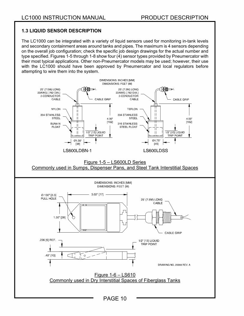
1.3 LIQUID SENSOR DESCRIPTION The LC1000 can be integrated with a variety of liquid sensors used for monitoring in-tank levels and secondary containment areas around tanks and pipes. The maximum is 4 sensors depending on the overall job configuration; check the specific job design drawings for the actual number and type specified. Figures 1-5 through 1-8 show four (4) sensor types provided by Pneumercator with their most typical applications. Other non-Pneumercator models may be used; however, their use with the LC1000 should have been approved by Pneumercator and local regulators before attempting to wire them into the system.
Figure 1-5 – LS600LD Series
Commonly used in Sumps, Dispenser Pans, and Steel Tank Interstitial Spaces
Figure 1-6 – LS610 Commonly used in Dry Interstitial Spaces of Fiberglass Tanks
DRAWING NO. 20006 REV. D
4.00"[102]
Ø1.50"[38]
Ø1.75"[45]
1/2" [13] LIQUIDTRIP POINT
304 STAINLESSSTEEL
BUNA NFLOAT
NYLON
25' (7.5M) LONG22AWG [.762 DIA.]
2-CONDUCTORCABLE
TEFLON
304 STAINLESSSTEEL
316 STAINLESSSTEEL FLOAT
LS600LDBN-1 LS600LDSS
4.00"[102]
1/2" [13] LIQUIDTRIP POINT
DIMENSIONS: INCHES [MM]DIMENSIONS: FEET (M)
CABLE GRIP CABLE GRIP
25' (7.5M) LONG22AWG [.762 DIA.]
2-CONDUCTORCABLE
DRAWING NO. 20008 REV. A
.236 [6] REF.
.40" [10]
3.02" [77]
1.50" [38]
Ø.130" [3.3]PULL HOLE
1/2" [13] LIQUIDTRIP POINT
CABLE GRIP
25' (7.5M) LONGCABLE
DIMENSIONS: INCHES [MM]DIMENSIONS: FEET (M)
LC1000 INSTRUCTION MANUAL PRODUCT DESCRIPTION
PAGE 11
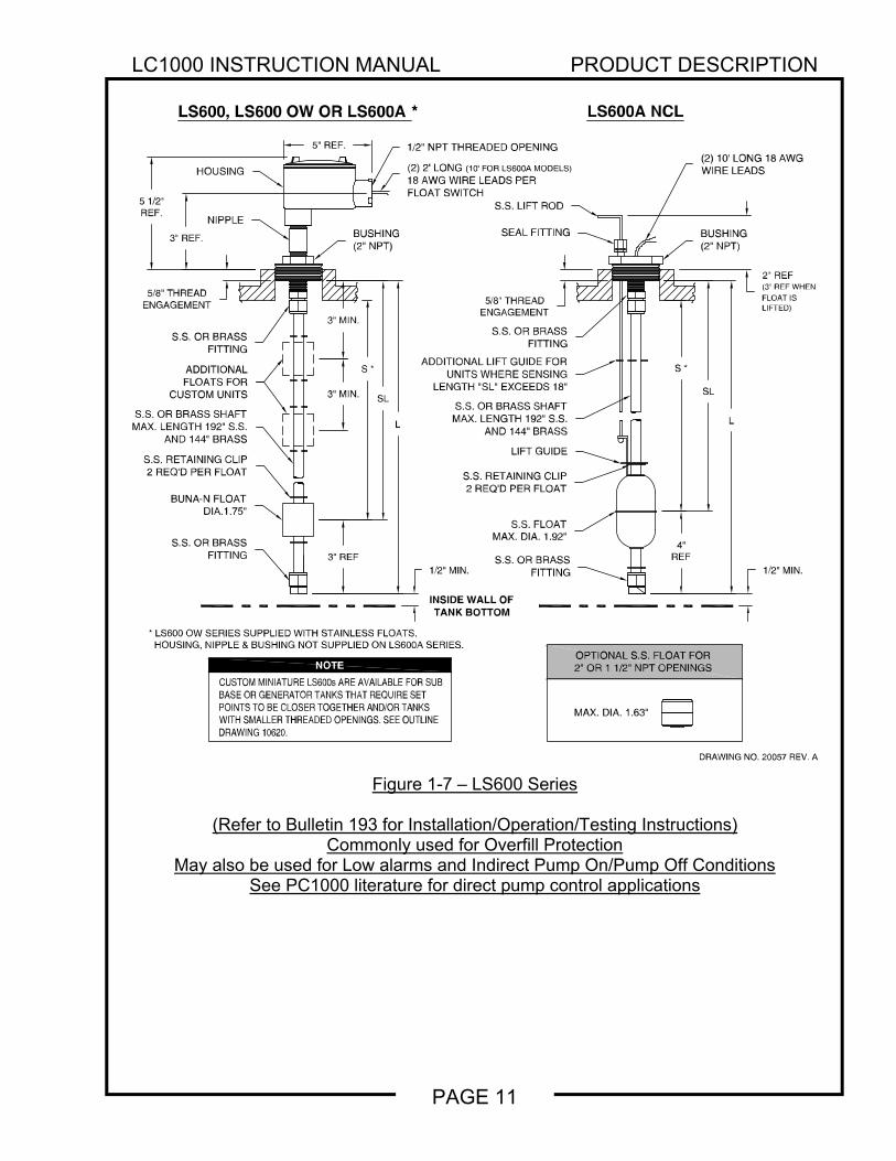
Figure 1-7 – LS600 Series
(Refer to Bulletin 193 for Installation/Operation/Testing Instructions) Commonly used for Overfill Protection
May also be used for Low alarms and Indirect Pump On/Pump Off Conditions See PC1000 literature for direct pump control applications
DRAWING NO. 20057 REV. A
SL
1/2" NPT THREADED OPENING
MAX. DIA. 1.63"
3" REF
S.S. RETAINING CLIP2 REQ'D PER FLOAT
LIFT GUIDE
SL
ADDITIONAL LIFT GUIDE FORUNITS WHERE SENSING
LENGTH "SL" EXCEEDS 18"
2" REF(3" REF WHENFLOAT ISLIFTED)
5" REF.
5 1/2"REF.
S.S. OR BRASSFITTING
S.S. FLOATMAX. DIA. 1.92"
S.S. RETAINING CLIP2 REQ'D PER FLOAT
S.S. OR BRASSFITTING
S.S. OR BRASSFITTING
S.S. OR BRASSFITTING
(2) 2' LONG (10' FOR LS600A MODELS)18 AWG WIRE LEADS PERFLOAT SWITCH
(2) 10' LONG 18 AWGWIRE LEADS
ADDITIONALFLOATS FOR
CUSTOM UNITSS.S. OR BRASS SHAFT
MAX. LENGTH 192" S.S.AND 144" BRASS
SEAL FITTING
S.S. LIFT ROD
BUSHING(2" NPT)
LS600A NCLLS600, LS600 OW OR LS600A *
BUNA-N FLOATDIA.1.75"
S.S. OR BRASS SHAFTMAX. LENGTH 192" S.S.
AND 144" BRASS
BUSHING(2" NPT)
NIPPLE
HOUSING
3" MIN.
3" MIN.
1/2" MIN.
4"REF
1/2" MIN.
OPTIONAL S.S. FLOAT FOR2" OR 1 1/2" NPT OPENINGS
INSIDE WALL OFTANK BOTTOM
L L
S *
5/8" THREADENGAGEMENT
S *
5/8" THREADENGAGEMENT
3" REF.
* LS600 OW SERIES SUPPLIED WITH STAINLESS FLOATS.HOUSING, NIPPLE & BUSHING NOT SUPPLIED ON LS600A SERIES.
CUSTOM MINIATURE LS600s ARE AVAILABLE FOR SUBBASE OR GENERATOR TANKS THAT REQUIRE SETPOINTS TO BE CLOSER TOGETHER AND/OR TANKSWITH SMALLER THREADED OPENINGS. SEE OUTLINEDRAWING 10620.
NOTE
LC1000 INSTRUCTION MANUAL PRODUCT DESCRIPTION
PAGE 12
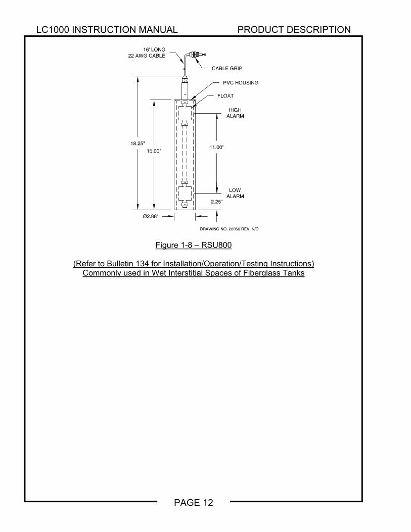
Figure 1-8 – RSU800
(Refer to Bulletin 134 for Installation/Operation/Testing Instructions) Commonly used in Wet Interstitial Spaces of Fiberglass Tanks
DRAWING NO. 20056 REV. N/C
16' LONG22 AWGCABLE
18.25"15.00"
CABLE GRIP
PVC HOUSING
11.00"
Ø2.88"
2.25"
HIGHALARM
LOWALARM
FLOAT
LC1000 INSTRUCTION MANUAL INSTALLATION DETAILS
PAGE 13
SECTION 2 – INSTALLATION DETAILS 2.1 INSTALLATION CHECKLIST
WARNING
Do NOT apply power to the LC1000 until its installation has been checked and found to be in accordance with these instructions; National Electric Code; Federal, State and Local codes; and other applicable safety codes. FAILURE TO COMPLY MAY RESULT IN PERSONAL INJURY, PROPERTY LOSS AND EQUIPMENT DAMAGE.
The following points should be reviewed in preparation for installation, and again when installation is complete.
1. Review Figures 3-2 and/or 3-3 to ensure that all of the safety/wiring requirements have been met.
2. Check that all equipment at job site matches the DESIGN DRAWING SPECIFICATIONS for
the tank sizes and control features required.
3. The console should be located as close as possible to the demarcation point of the hazardous area. Never mount inside the hazardous area. Note: If the LC1000 was provided with a NEMA 7 Explosion-proof enclosure, then it is permitted to install the LC1000 in the hazardous location provided that all fittings and conduit are explosion-proof and all applicable regulations are followed.
4. POWER to the console should be properly wired to a DEDICATED 120 VAC CIRCUIT
BREAKER. No other equipment can be powered from the same circuit breaker as the LC1000.
5. System cannot be connected to equipment that uses or generates more than 250 volts with respect to earth.
6. All LC1000 grounds must be terminated at the GND BUSS BAR in the same service panel as
LC1000 power. A grounding rod, coldwater pipe or other connection should not be used.
7. Do not drill or modify enclosure. Use only conduit entries provided. Failure to comply will void warranty and may present a safety hazard.
8. WATERPROOFING FIELD WIRE SPLICES using factory supplied splice kits is required for
proper system operation.
LC1000 INSTRUCTION MANUAL INSTALLATION DETAILS
PAGE 14
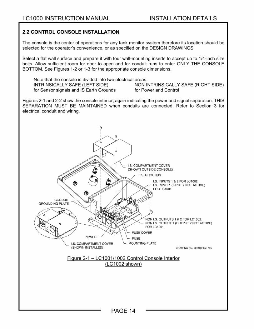
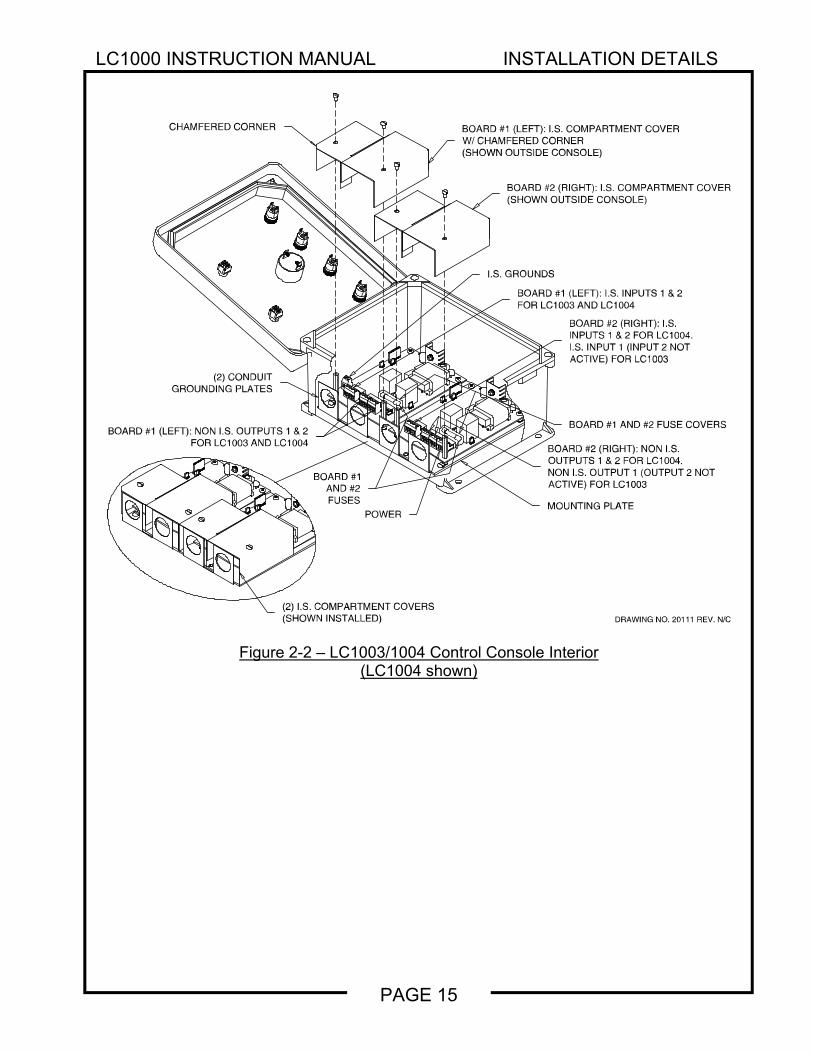
2.2 CONTROL CONSOLE INSTALLATION The console is the center of operations for any tank monitor system therefore its location should be selected for the operator’s convenience, or as specified on the DESIGN DRAWINGS. Select a flat wall surface and prepare it with four wall-mounting inserts to accept up to 1/4-inch size bolts. Allow sufficient room for door to open and for conduit runs to enter ONLY THE CONSOLE BOTTOM. See Figures 1-2 or 1-3 for the appropriate console dimensions.
Note that the console is divided into two electrical areas: INTRINSICALLY SAFE (LEFT SIDE) NON INTRINSICALLY SAFE (RIGHT SIDE) for Sensor signals and IS Earth Grounds for Power and Control
Figures 2-1 and 2-2 show the console interior, again indicating the power and signal separation. THIS SEPARATION MUST BE MAINTAINED when conduits are connected. Refer to Section 3 for electrical conduit and wiring.
Figure 2-1 – LC1001/1002 Control Console Interior (LC1002 shown)
DRAWING NO. 20110 REV. N/C
I.S. COMPARTMENT COVER(SHOWN OUTSIDE CONSOLE)
FUSE
FUSE COVER
I.S. COMPARTMENT COVER(SHOWN INSTALLED)
MOUNTING PLATE
I.S. GROUNDS
I.S. INPUTS1 & 2 FORLC1002.I.S. INPUT 1 (INPUT 2 NOT ACTIVE)FOR LC1001
NON I.S. OUTPUTS 1 & 2 FOR LC1002.NON I.S. OUTPUT 1 (OUTPUT 2 NOT ACTIVE)FOR LC1001
POWER
CONDUITGROUNDING PLATE
LC1000 INSTRUCTION MANUAL INSTALLATION DETAILS
PAGE 15
Figure 2-2 – LC1003/1004 Control Console Interior (LC1004 shown)
DRAWING NO. 20111 REV. N/C
CHAMFERED CORNER BOARD #1 (LEFT): I.S. COMPARTMENT COVERW/ CHAMFERED CORNE R(SHOWN OUTSIDE CONSOLE)
I.S. GROUNDS
BOARD #1 (LEFT): I.S. INPUTS 1 & 2FOR LC1003 AND LC1004
BOARD #1 (LEFT): NON I.S. OUTPUTS 1 & 2FOR LC1003 AND LC1004
(2) CONDUITGROUNDING PLATES
POWER
(2) I.S. COMPARTMENT COVERS(SHOWN INSTALLED)
BOARD #2 (RIGHT): I.S.INPUTS 1 & 2 FOR LC1004.I.S. INPUT 1 (INPUT 2 NOTACTIVE) FOR LC1003
BOARD #2 (RIGHT): NON I.S.OUTPUTS 1 & 2 FOR LC1004.NON I.S. OUTPUT 1 (OUTPUT 2 NOTACTIVE) FOR LC1003
BOARD #1 AND #2 FUSE COVERS
BOARD #2 (RIGHT): I.S. COMPARTMENT COVER(SHOWN OUTSIDE CONSOLE)
MOUNTING PLATE
BOARD #1AND #2FUSES
LC1000 INSTRUCTION MANUAL INSTALLATION DETAILS
PAGE 16
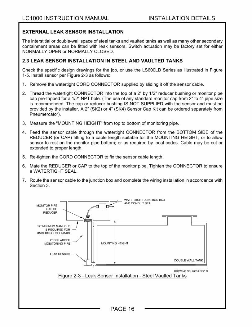
EXTERNAL LEAK SENSOR INSTALLATION
The interstitial or double-wall space of steel tanks and vaulted tanks as well as many other secondary containment areas can be fitted with leak sensors. Switch actuation may be factory set for either NORMALLY OPEN or NORMALLY CLOSED.
2.3 LEAK SENSOR INSTALLATION IN STEEL AND VAULTED TANKS
Check the specific design drawings for the job, or use the LS600LD Series as illustrated in Figure 1-5. Install sensor per Figure 2-3 as follows:
1. Remove the watertight CORD CONNECTOR supplied by sliding it off the sensor cable.
2. Thread the watertight CONNECTOR into the top of a 2" by 1/2" reducer bushing or monitor pipe cap pre-tapped for a 1/2" NPT hole. (The use of any standard monitor cap from 2" to 4" pipe size is recommended. The cap or reducer bushing IS NOT SUPPLIED with the sensor and must be provided by the installer. A 2” (SK2) or 4” (SK4) Sensor Cap Kit can be ordered separately from Pneumercator).
3. Measure the "MOUNTING HEIGHT" from top to bottom of monitoring pipe.
4. Feed the sensor cable through the watertight CONNECTOR from the BOTTOM SIDE of the REDUCER (or CAP) fitting to a cable length suitable for the MOUNTING HEIGHT; or to allow sensor to rest on the monitor pipe bottom; or as required by local codes. Cable may be cut or extended to proper length.
5. Re-tighten the CORD CONNECTOR to fix the sensor cable length.
6. Mate the REDUCER or CAP to the top of the monitor pipe. Tighten the CONNECTOR to ensure a WATERTIGHT SEAL.
7. Route the sensor cable to the junction box and complete the wiring installation in accordance with Section 3.
Figure 2-3 - Leak Sensor Installation - Steel Vaulted Tanks
DRAWING NO. 20016 REV. C
DOUBLE WALL TANK
WATERTIGHT JUNCTION BOXAND CONDUIT SEAL
MONITOR PIPECAP OR
REDUCER
MOUNTING HEIGHT
12" MINIMUM MANHOLEIS REQUIRED FOR
UNDERGROUND TANKS
2" OR LARGERMONITORING PIPE
LEAK SENSOR
LC1000 INSTRUCTION MANUAL INSTALLATION DETAILS
PAGE 17
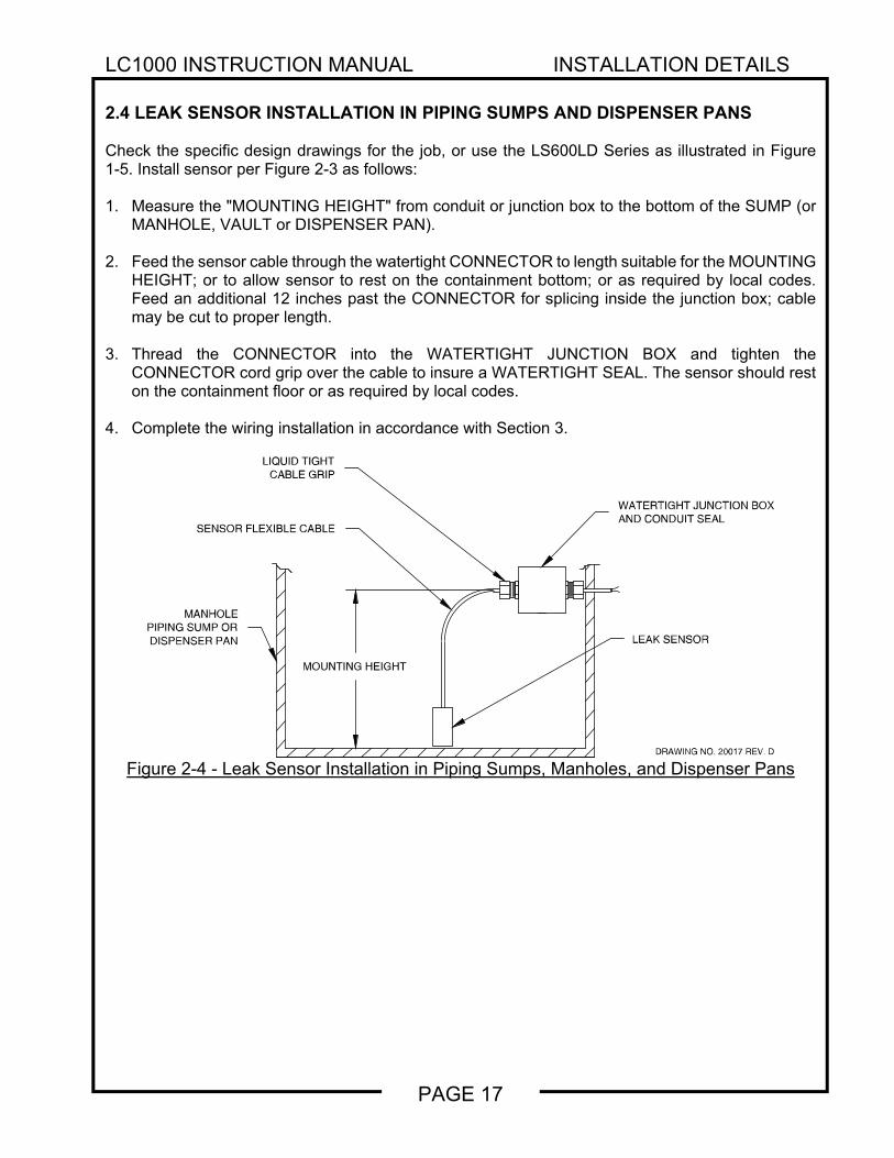
2.4 LEAK SENSOR INSTALLATION IN PIPING SUMPS AND DISPENSER PANS Check the specific design drawings for the job, or use the LS600LD Series as illustrated in Figure 1-5. Install sensor per Figure 2-3 as follows: 1. Measure the "MOUNTING HEIGHT" from conduit or junction box to the bottom of the SUMP (or
MANHOLE, VAULT or DISPENSER PAN). 2. Feed the sensor cable through the watertight CONNECTOR to length suitable for the MOUNTING
HEIGHT; or to allow sensor to rest on the containment bottom; or as required by local codes. Feed an additional 12 inches past the CONNECTOR for splicing inside the junction box; cable may be cut to proper length.
3. Thread the CONNECTOR into the WATERTIGHT JUNCTION BOX and tighten the
CONNECTOR cord grip over the cable to insure a WATERTIGHT SEAL. The sensor should rest on the containment floor or as required by local codes.
4. Complete the wiring installation in accordance with Section 3.
Figure 2-4 - Leak Sensor Installation in Piping Sumps, Manholes, and Dispenser Pans
MOUNTING HEIGHT
SENSOR FLEXIBLE CABLE
LIQUID TIGHTCABLE GRIP
WATERTIGHT JUNCTION BOXAND CONDUIT SEAL
LEAK SENSOR
MANHOLEPIPING SUMP ORDISPENSER PAN
DRAWING NO. 20017 REV. D
LC1000 INSTRUCTION MANUAL INSTALLATION DETAILS
PAGE 18
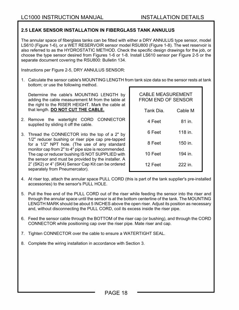
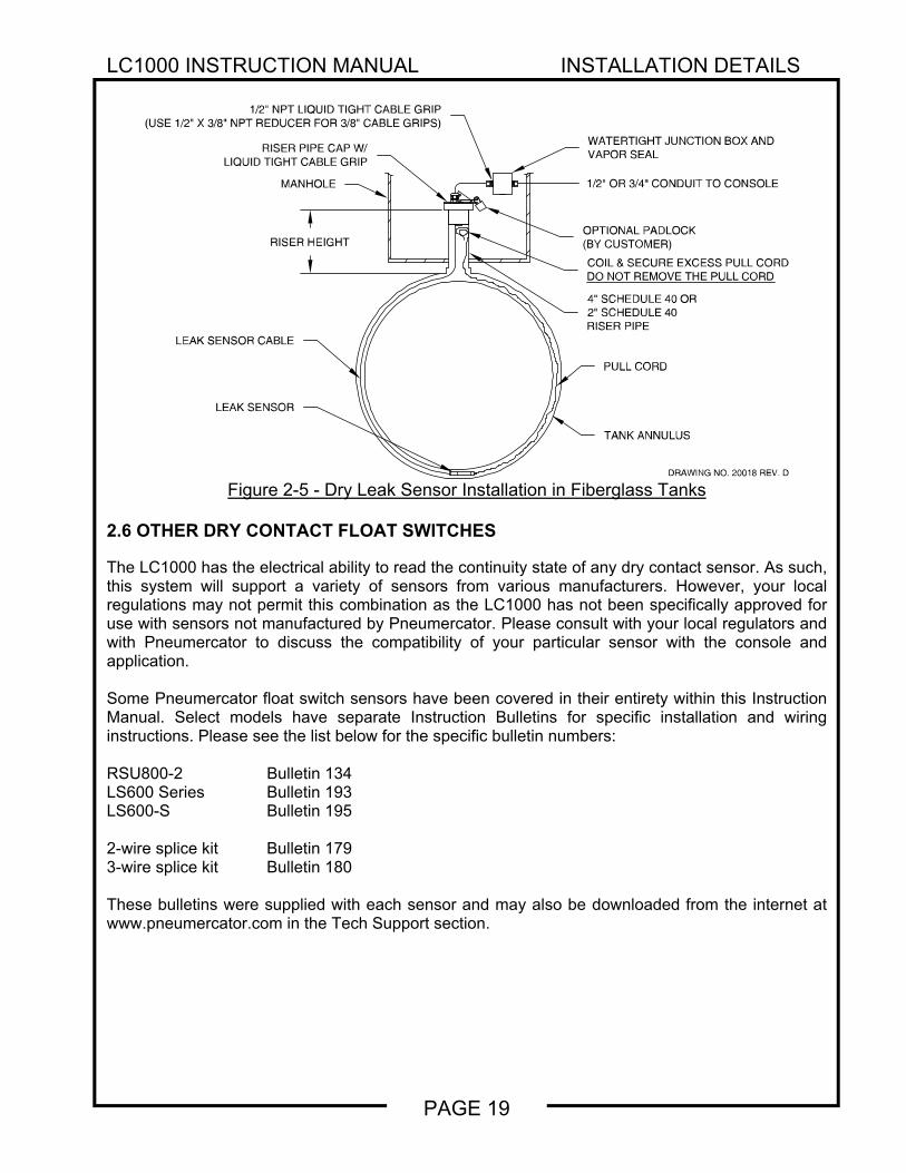
2.5 LEAK SENSOR INSTALLATION IN FIBERGLASS TANK ANNULUS The annular space of fiberglass tanks can be fitted with either a DRY ANNULUS type sensor, model LS610 (Figure 1-6), or a WET RESERVOIR sensor model RSU800 (Figure 1-8). The wet reservoir is also referred to as the HYDROSTATIC METHOD. Check the specific design drawings for the job, or choose the type sensor desired from Figures 1-6 or 1-8. Install LS610 sensor per Figure 2-5 or the separate document covering the RSU800: Bulletin 134. Instructions per Figure 2-5, DRY ANNULUS SENSOR: 1. Calculate the sensor cable's MOUNTING LENGTH from tank size data so the sensor rests at tank
bottom; or use the following method.
Determine the cable's MOUNTING LENGTH by adding the cable measurement M from the table at the right to the RISER HEIGHT. Mark the cable at that length. DO NOT CUT THE CABLE.
2. Remove the watertight CORD CONNECTOR
supplied by sliding it off the cable. 3. Thread the CONNECTOR into the top of a 2" by
1/2" reducer bushing or riser pipe cap pre-tapped for a 1/2" NPT hole. (The use of any standard monitor cap from 2" to 4" pipe size is recommended. The cap or reducer bushing IS NOT SUPPLIED with the sensor and must be provided by the installer. A 2” (SK2) or 4” (SK4) Sensor Cap Kit can be ordered separately from Pneumercator).
4. At riser top, attach the annular space PULL CORD (this is part of the tank supplier's pre-installed
accessories) to the sensor's PULL HOLE. 5. Pull the free end of the PULL CORD out of the riser while feeding the sensor into the riser and
through the annular space until the sensor is at the bottom centerline of the tank. The MOUNTING LENGTH MARK should be about 5 INCHES above the open riser. Adjust its position as necessary and, without disconnecting the PULL CORD, coil its excess inside the riser pipe.
6. Feed the sensor cable through the BOTTOM of the riser cap (or bushing), and through the CORD
CONNECTOR while positioning cap over the riser pipe. Mate riser and cap. 7. Tighten CONNECTOR over the cable to ensure a WATERTIGHT SEAL. 8. Complete the wiring installation in accordance with Section 3.
CABLE MEASUREMENT FROM END OF SENSOR
Tank Dia. Cable M 4 Feet 81 in. 6 Feet 118 in. 8 Feet 150 in. 10 Feet 194 in.
12 Feet 222 in.
LC1000 INSTRUCTION MANUAL INSTALLATION DETAILS
PAGE 19
Figure 2-5 - Dry Leak Sensor Installation in Fiberglass Tanks
2.6 OTHER DRY CONTACT FLOAT SWITCHES The LC1000 has the electrical ability to read the continuity state of any dry contact sensor. As such, this system will support a variety of sensors from various manufacturers. However, your local regulations may not permit this combination as the LC1000 has not been specifically approved for use with sensors not manufactured by Pneumercator. Please consult with your local regulators and with Pneumercator to discuss the compatibility of your particular sensor with the console and application. Some Pneumercator float switch sensors have been covered in their entirety within this Instruction Manual. Select models have separate Instruction Bulletins for specific installation and wiring instructions. Please see the list below for the specific bulletin numbers: RSU800-2 Bulletin 134 LS600 Series Bulletin 193 LS600-S Bulletin 195 2-wire splice kit Bulletin 179 3-wire splice kit Bulletin 180 These bulletins were supplied with each sensor and may also be downloaded from the internet at www.pneumercator.com in the Tech Support section.
DRAWING NO. 20018 REV. D
RISER PIPE CAP W/LIQUID TIGHT CABLE GRIP
WATERTIGHT JUNCTION BOX ANDVAPOR SEAL
1/2" NPT LIQUID TIGHT CABLE GRIP(USE 1/2" X 3/8" NPT REDUCER FOR 3/8" CABLE GRIPS)
1/2" OR 3/4" CONDUIT TO CONSOLE
LEAK SENSOR CABLE
MANHOLE
RISER HEIGHT
PULL CORD
TANK ANNULUS
LEAK SENSOR
COIL & SECURE EXCESS PULL CORDDO NOT REMOVE THE PULLCORD
4" SCHEDULE 40 OR2" SCHEDULE 40RISER PIPE
OPTIONAL PADLOCK(BY CUSTOMER)
LC1000 INSTRUCTION MANUAL WIRING
PAGE 20
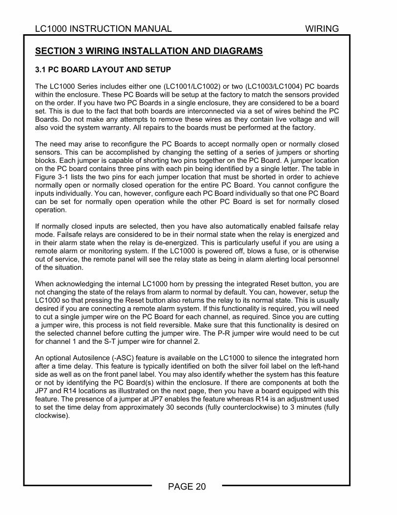
SECTION 3 WIRING INSTALLATION AND DIAGRAMS 3.1 PC BOARD LAYOUT AND SETUP The LC1000 Series includes either one (LC1001/LC1002) or two (LC1003/LC1004) PC boards within the enclosure. These PC Boards will be setup at the factory to match the sensors provided on the order. If you have two PC Boards in a single enclosure, they are considered to be a board set. This is due to the fact that both boards are interconnected via a set of wires behind the PC Boards. Do not make any attempts to remove these wires as they contain live voltage and will also void the system warranty. All repairs to the boards must be performed at the factory. The need may arise to reconfigure the PC Boards to accept normally open or normally closed sensors. This can be accomplished by changing the setting of a series of jumpers or shorting blocks. Each jumper is capable of shorting two pins together on the PC Board. A jumper location on the PC board contains three pins with each pin being identified by a single letter. The table in Figure 3-1 lists the two pins for each jumper location that must be shorted in order to achieve normally open or normally closed operation for the entire PC Board. You cannot configure the inputs individually. You can, however, configure each PC Board individually so that one PC Board can be set for normally open operation while the other PC Board is set for normally closed operation. If normally closed inputs are selected, then you have also automatically enabled failsafe relay mode. Failsafe relays are considered to be in their normal state when the relay is energized and in their alarm state when the relay is de-energized. This is particularly useful if you are using a remote alarm or monitoring system. If the LC1000 is powered off, blows a fuse, or is otherwise out of service, the remote panel will see the relay state as being in alarm alerting local personnel of the situation. When acknowledging the internal LC1000 horn by pressing the integrated Reset button, you are not changing the state of the relays from alarm to normal by default. You can, however, setup the LC1000 so that pressing the Reset button also returns the relay to its normal state. This is usually desired if you are connecting a remote alarm system. If this functionality is required, you will need to cut a single jumper wire on the PC Board for each channel, as required. Since you are cutting a jumper wire, this process is not field reversible. Make sure that this functionality is desired on the selected channel before cutting the jumper wire. The P-R jumper wire would need to be cut for channel 1 and the S-T jumper wire for channel 2. An optional Autosilence (-ASC) feature is available on the LC1000 to silence the integrated horn after a time delay. This feature is typically identified on both the silver foil label on the left-hand side as well as on the front panel label. You may also identify whether the system has this feature or not by identifying the PC Board(s) within the enclosure. If there are components at both the JP7 and R14 locations as illustrated on the next page, then you have a board equipped with this feature. The presence of a jumper at JP7 enables the feature whereas R14 is an adjustment used to set the time delay from approximately 30 seconds (fully counterclockwise) to 3 minutes (fully clockwise).
LC1000 INSTRUCTION MANUAL WIRING
PAGE 21
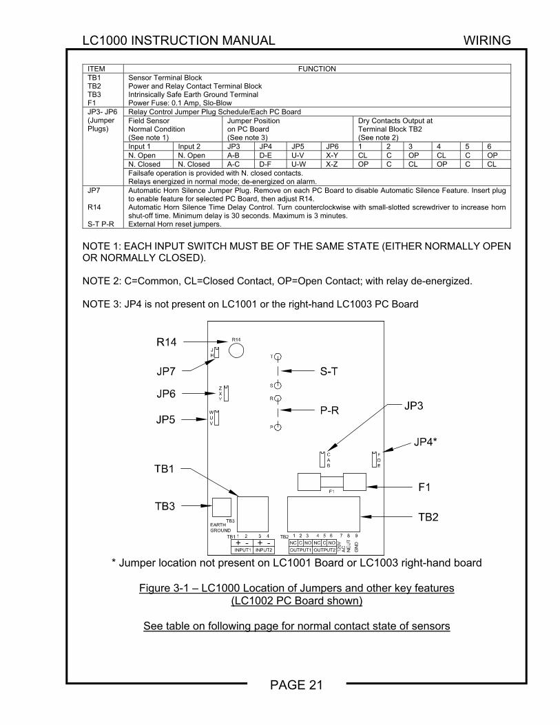
ITEM FUNCTIONTB1 TB2 TB3 F1
Sensor Terminal Block Power and Relay Contact Terminal Block Intrinsically Safe Earth Ground Terminal Power Fuse: 0.1 Amp, Slo-Blow
JP3- JP6 (Jumper Plugs)
Relay Control Jumper Plug Schedule/Each PC BoardField Sensor Normal Condition (See note 1)
Jumper Position on PC Board (See note 3)
Dry Contacts Output at Terminal Block TB2 (See note 2)
Input 1 Input 2 JP3 JP4 JP5 JP6 1 2 3 4 5 6N. Open N. Open A-B D-E U-V X-Y CL C OP CL C OPN. Closed N. Closed A-C D-F U-W X-Z OP C CL OP C CLFailsafe operation is provided with N. closed contacts. Relays energized in normal mode; de-energized on alarm.
JP7 R14 S-T P-R
Automatic Horn Silence Jumper Plug. Remove on each PC Board to disable Automatic Silence Feature. Insert plug to enable feature for selected PC Board, then adjust R14. Automatic Horn Silence Time Delay Control. Turn counterclockwise with small-slotted screwdriver to increase horn shut-off time. Minimum delay is 30 seconds. Maximum is 3 minutes. External Horn reset jumpers.
NOTE 1: EACH INPUT SWITCH MUST BE OF THE SAME STATE (EITHER NORMALLY OPEN OR NORMALLY CLOSED). NOTE 2: C=Common, CL=Closed Contact, OP=Open Contact; with relay de-energized. NOTE 3: JP4 is not present on LC1001 or the right-hand LC1003 PC Board
* Jumper location not present on LC1001 Board or LC1003 right-hand board
Figure 3-1 – LC1000 Location of Jumpers and other key features
(LC1002 PC Board shown)
See table on following page for normal contact state of sensors
GN
D
9
EARTHGROUND
TB2
INPUT1+
TB1
-1 2
INPUT2+ -3 4
OUTPUT2OUTPUT1
NC C
1 2
NO NC
3 4
120V
NOC
5 6
AC
NE
UT
87
TB3
F1
BAC
YXZ
V
WU
HJ
R
P
S
T
R14
EDF
S-T
P-R
JP4*
F1
TB2
R14
JP6
JP5
TB3
TB1
JP7
JP3
LC1000 INSTRUCTION MANUAL WIRING
PAGE 22
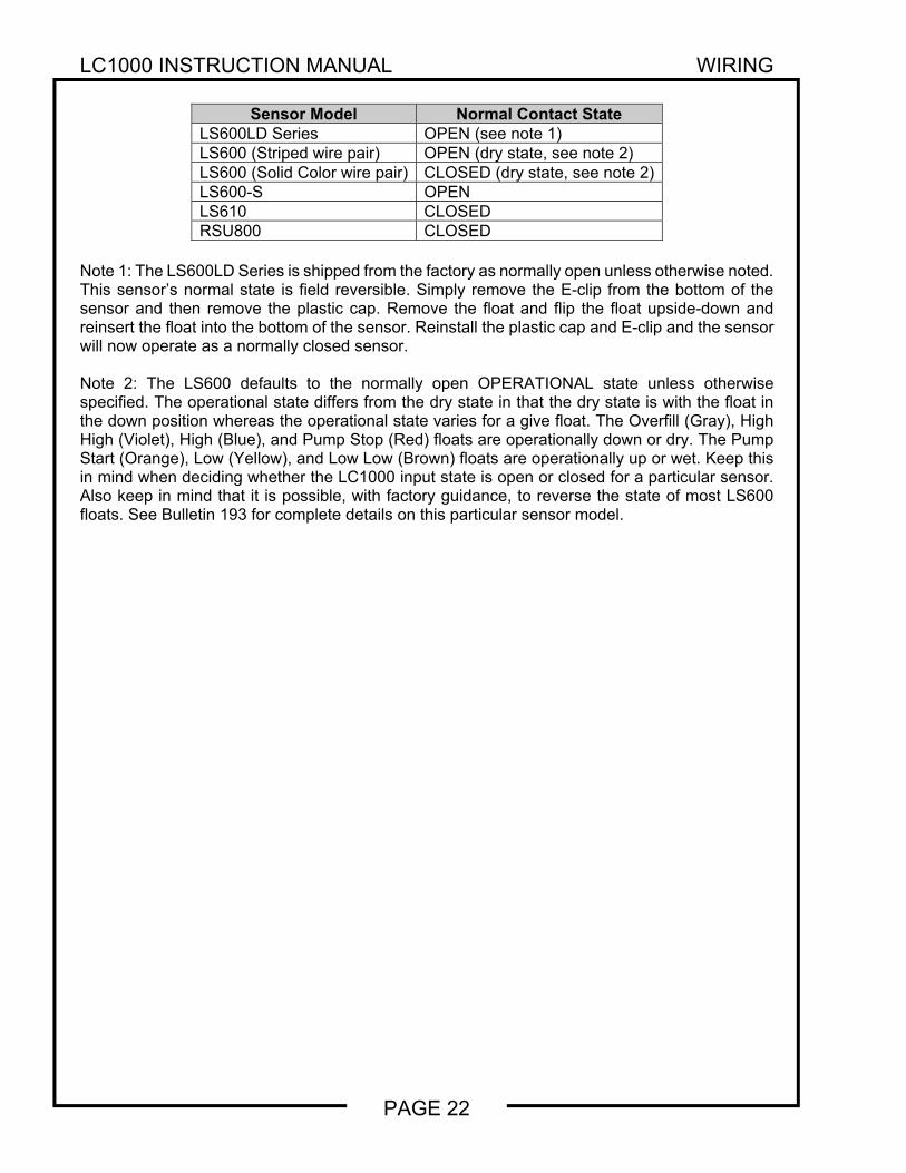
Sensor Model Normal Contact State
LS600LD Series OPEN (see note 1)LS600 (Striped wire pair) OPEN (dry state, see note 2)LS600 (Solid Color wire pair) CLOSED (dry state, see note 2) LS600-S OPENLS610 CLOSEDRSU800 CLOSED
Note 1: The LS600LD Series is shipped from the factory as normally open unless otherwise noted. This sensor’s normal state is field reversible. Simply remove the E-clip from the bottom of the sensor and then remove the plastic cap. Remove the float and flip the float upside-down and reinsert the float into the bottom of the sensor. Reinstall the plastic cap and E-clip and the sensor will now operate as a normally closed sensor. Note 2: The LS600 defaults to the normally open OPERATIONAL state unless otherwise specified. The operational state differs from the dry state in that the dry state is with the float in the down position whereas the operational state varies for a give float. The Overfill (Gray), High High (Violet), High (Blue), and Pump Stop (Red) floats are operationally down or dry. The Pump Start (Orange), Low (Yellow), and Low Low (Brown) floats are operationally up or wet. Keep this in mind when deciding whether the LC1000 input state is open or closed for a particular sensor. Also keep in mind that it is possible, with factory guidance, to reverse the state of most LS600 floats. See Bulletin 193 for complete details on this particular sensor model.
LC1000 INSTRUCTION MANUAL WIRING
PAGE 23
CAUTION
Sensors connected to the LC1000 are usually installed in explosion hazard areas typical of hydrocarbon fuel tanks. For these applications, it is CRITICAL that electrical conduit and wiring be installed by qualified installers familiar with all provisions of the National Electrical Code relating to equipment intended for use in EXPLOSION HAZARD areas. The primary concern is to maintain physical separation between intrinsically safe and non-intrinsically safe wiring by running separate conduit attached to the control console at the designated knockouts. ALL conduits carrying sensor wiring into the hazardous area MUST be fitted with standard vapor seal-off fittings at all field junction boxes and again where the conduit first enters the non-hazardous area. FAILURE TO COMPLY MAY RESULT IN PERSONAL INJURY, PROPERTY LOSS AND EQUIPMENT DAMAGE.
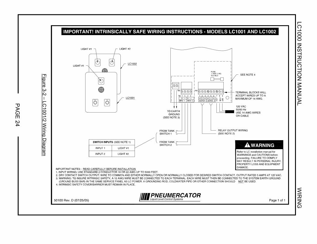
3.2 SYSTEM WIRING Figures 3-2 and 3-3 are typical System Wiring Diagrams that must be followed when running conduit and wires between the HAZARDOUS TANK area and the NON-HAZARDOUS CONSOLE area. This follows FM and other codes for proper installation. SENSOR WIRING INSTALLATION. Refer to Figures 1-4 through 1-8 for console conduit openings and specific sensors that will be wired into the LC1000 system. Install wiring as follows: 1. Install 1/2" rigid conduit from all sensor areas to the LC1000 console.
CAUTION
All sensor wiring from the LC1000 console may be run in the same conduit. NO OTHER WIRING MAY BE RUN IN THESE CONDUITS. NEVER RUN POWER WIRES IN THESE CONDUITS. FAILURE TO COMPLY MAY RESULT IN PERSONAL INJURY, PROPERTY LOSS AND EQUIPMENT DAMAGE.
2. At appropriate locations along the conduit runs (see Figures 2-3 through 2-5 and/or
appropriate sensor Instruction Bulletins) install watertight couplings and approved VAPOR SEAL-OFF fittings.
3. At each sensor location install a WATERTIGHT ELECTRICAL JUNCTION BOX. Allow
enough room around the sensor tank fitting for proper installation of the sensor and all conduit/junction box fittings, and for later removal if necessary.
4. Attach the conduit at the LC1000 console ONLY to the 1/2" conduit knockout designated for
Intrinsically Safe wiring (see Figure 1-4). Use NEMA 4 fittings for outdoor locations.
LC1000 IN
ST
RU
CT
ION
MA
NU
AL
WIR
ING
PA
GE
24
Figure 3-2 – LC
1001/2 Wiring D
iagram
PNEUMERCATORLiquid Level Control Systems50100 Rev. D (07/25/05) Page 1 of 1
NC C NO NC C NO
RELAY OUTPUT WIRING(SEE NOTE 2)
FROM TANKSWITCH 1
TO EARTHGROUND
(SEE NOTE 3)
120 VAC50/60 HzUSE 14 AWG WIRESOR CABLE
LIGHT #1 LIGHT #2
FROM TANKSWITCH 2
SWITCH INPUTS (SEE NOTE 1)
INPUT 1
INPUT 2
LIGHT #1
LIGHT #2
IMPORTANT NOTES - READ CAREFULLY BEFORE INSTALLATION1. INPUT WIRING: USE STANDARD 2 CONDUCTOR 18 OR 22 AWG UP TO 5000 FEET.2. DRY CONTACT SWITCH OUTPUT: WIRE TO COMMON AND EITHER NORMALLY OPEN OR NORMALLY CLOSED FOR DESIRED SWITCH CONTACT. OUTPUT RATED 3 AMPS AT 120 VAC.3. WARNING: TO INSURE INTRINSIC SAFETY, A 12 AWG WIRE MUST BE CONNECTED TO EACH TERMINAL. EACH WIRE MUST THEN BE CONNECTED TO THE SYSTEM EARTH GROUND (GROUND BUSS BAR) IN THE SAME SERVICE PANEL AS LC POWER. A GROUNDING ROD, COLDWATER PIPE OR OTHER CONNECTION SHOULD NOT BE USED.4. INTRINSIC SAFETY COVER/BARRIER MUST REMAIN IN PLACE.
RESET TEST
LIGHT #1
HO
T
LC1002
LC1001
SEE NOTE 4FUSE-.1 AMP, 3 AG.SLO BLO
TERMINAL BLOCKS WILLACCEPT WIRES UP TO AMAXIMUM OF 14 AWG.
Refer to LC installation manual forWARNINGS and CAUTIONS beforeproceeding. FAILURE TO COMPLYMAY RESULT IN PERSONAL INJURY,PROPERTY LOSS AND EQUIPMENTDAMAGE.
! WARNING
IMPORTANT! INTRINSICALLY SAFE WIRING INSTRUCTIONS - MODELS LC1001 AND LC1002

LC1000 IN
ST
RU
CT
ION
MA
NU
AL
WIR
ING
PA
GE
25
Figure 3-3 – LC
1003/4 Wiring D
iagram
Refer to LC installation manual forWARNINGS and CAUTIONS beforeproceeding. FAILURE TO COMPLYMAY RESULT IN PERSONAL INJURY,PROPERTY LOSS AND EQUIPMENTDAMAGE.
TERMINAL BLOCKSWILL ACCEPT WIRESUP TO AMAXIMUM OF14 AWG.
SEENOTE 4
HO
T
LIGHT #2
LIGHT #1
INPUT 2
INPUT 1
SWITCH INPUTS (SEE NOTE 1)FROM TANKSWITCH 4
120 VAC50/60 HzUSE 14 AWGWIRES OR CABLE
TO EARTHGROUND
(SEE NOTE 3)
FROM TANKSWITCH 3
RELAY OUTPUT WIRING(SEE NOTE 2)
NOCNCNOCNC
Page 1 of 150101 Rev. D (07/25/05) Liquid Level Control SystemsPNEUMERCATOR
WARNING!
TESTRESET
LIGHT #1
LIGHT #4
LIGHT #3
LC1004
LC1003
LIGHT #1
BOARD #1
BOARD #2LIGHT #4
LIGHT #3
INPUT 2
INPUT 1
FUSE-.1 AMP, 3 AG.SLO BLO
FROM TANKSWITCH 2
FROM TANKSWITCH 1
RELAY OUTPUTWIRING
(SEE NOTE 2)
NOCNCNOCNC
BOARD #1 (LEFT SIDE)
SEENOTE 4 FUSE-
.1 AMP, 3 AG.SLO BLO
BOARD #2 (RIGHT SIDE)
IMPORTANT NOTES - READ CAREFULLY BEFORE INSTALLATION1. INPUT WIRING: USE STANDARD 2 CONDUCTOR 18 OR 22 AWG UP TO 5000 FEET.2. DRY CONTACT SWITCH OUTPUT: WIRE TO COMMON AND EITHER NORMALLY OPEN OR NORMALLY CLOSED FOR DESIRED SWITCH CONTACT. OUTPUT RATED 3 AMPS AT 120 VAC.3. WARNING: TO INSURE INTRINSIC SAFETY, A 12 AWG WIRE MUST BE CONNECTED TO EACH TERMINAL. EACH WIRE MUST THEN BE CONNECTED TO THE SYSTEM EARTH GROUND (GROUND BUSS BAR) IN THE SAME SERVICE PANEL AS LC POWER. A GROUNDING ROD, COLDWATER PIPE OR OTHER CONNECTION SHOULD NOT BE USED.4. INTRINSIC SAFETY COVER/BARRIER MUST REMAIN IN PLACE.
IMPORTANT! INTRINSICALLY SAFE WIRING INSTRUCTIONS - MODELS LC1003 AND LC1004
LC1000 INSTRUCTION MANUAL WIRING
PAGE 26
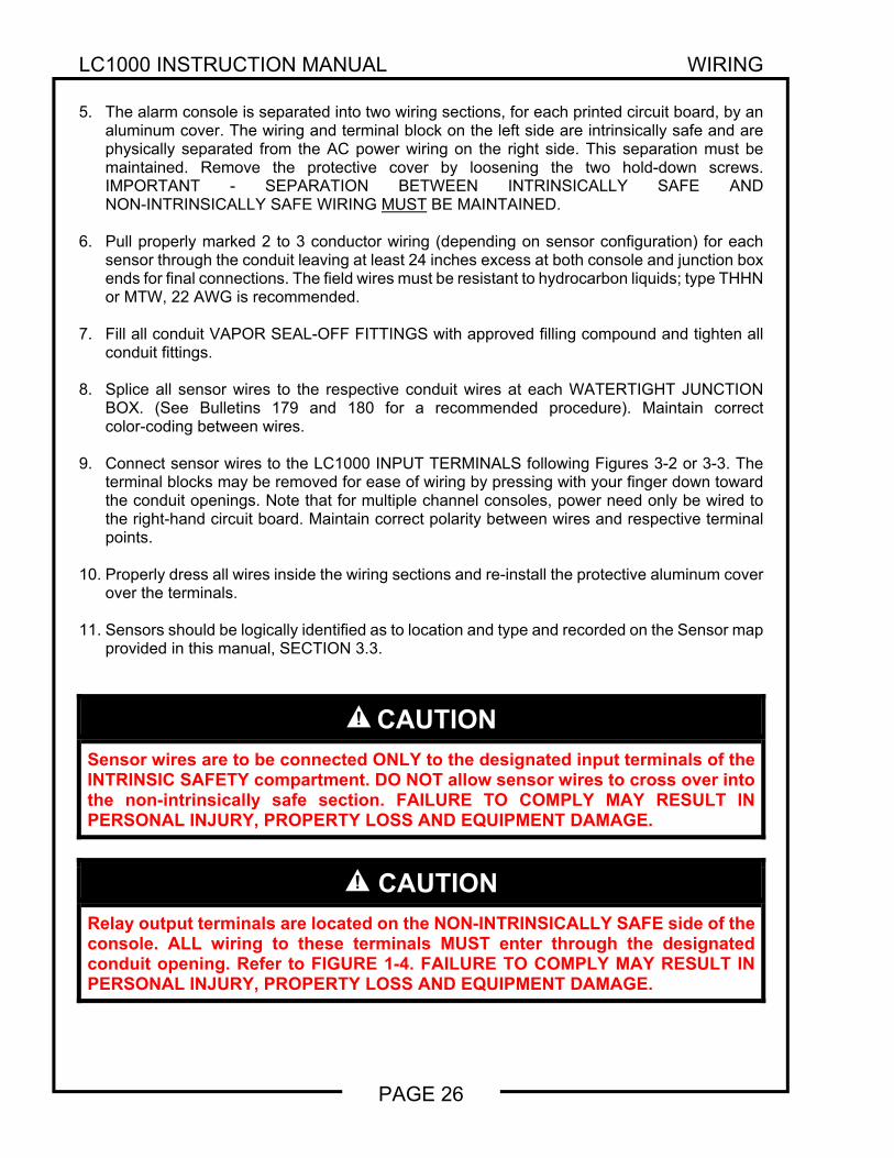
5. The alarm console is separated into two wiring sections, for each printed circuit board, by an
aluminum cover. The wiring and terminal block on the left side are intrinsically safe and are physically separated from the AC power wiring on the right side. This separation must be maintained. Remove the protective cover by loosening the two hold-down screws. IMPORTANT - SEPARATION BETWEEN INTRINSICALLY SAFE AND NON-INTRINSICALLY SAFE WIRING MUST BE MAINTAINED.
6. Pull properly marked 2 to 3 conductor wiring (depending on sensor configuration) for each
sensor through the conduit leaving at least 24 inches excess at both console and junction box ends for final connections. The field wires must be resistant to hydrocarbon liquids; type THHN or MTW, 22 AWG is recommended.
7. Fill all conduit VAPOR SEAL-OFF FITTINGS with approved filling compound and tighten all
conduit fittings. 8. Splice all sensor wires to the respective conduit wires at each WATERTIGHT JUNCTION
BOX. (See Bulletins 179 and 180 for a recommended procedure). Maintain correct color-coding between wires.
9. Connect sensor wires to the LC1000 INPUT TERMINALS following Figures 3-2 or 3-3. The
terminal blocks may be removed for ease of wiring by pressing with your finger down toward the conduit openings. Note that for multiple channel consoles, power need only be wired to the right-hand circuit board. Maintain correct polarity between wires and respective terminal points.
10. Properly dress all wires inside the wiring sections and re-install the protective aluminum cover
over the terminals. 11. Sensors should be logically identified as to location and type and recorded on the Sensor map
provided in this manual, SECTION 3.3.
CAUTION
Sensor wires are to be connected ONLY to the designated input terminals of the INTRINSIC SAFETY compartment. DO NOT allow sensor wires to cross over into the non-intrinsically safe section. FAILURE TO COMPLY MAY RESULT IN PERSONAL INJURY, PROPERTY LOSS AND EQUIPMENT DAMAGE.
CAUTION
Relay output terminals are located on the NON-INTRINSICALLY SAFE side of the console. ALL wiring to these terminals MUST enter through the designated conduit opening. Refer to FIGURE 1-4. FAILURE TO COMPLY MAY RESULT IN PERSONAL INJURY, PROPERTY LOSS AND EQUIPMENT DAMAGE.
LC1000 INSTRUCTION MANUAL WIRING
PAGE 27
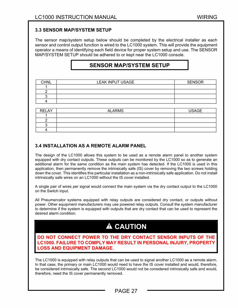
3.3 SENSOR MAP/SYSTEM SETUP The sensor map/system setup below should be completed by the electrical installer as each sensor and control output function is wired to the LC1000 system. This will provide the equipment operator a means of identifying each field device for proper system setup and use. The SENSOR MAP/SYSTEM SETUP should be adhered to or kept near the LC1000 console.
CHNL LEAK INPUT USAGE SENSOR1 2 3 4
RELAY ALARMS USAGE1 2 3 4
3.4 INSTALLATION AS A REMOTE ALARM PANEL The design of the LC1000 allows this system to be used as a remote alarm panel to another system equipped with dry contact outputs. These outputs can be monitored by the LC1000 so as to generate an additional alarm for the same condition as the main system has detected. If the LC1000 is used in this application, then permanently remove the intrinsically safe (IS) cover by removing the two screws holding down the cover. This identifies this particular installation as a non-intrinsically safe application. Do not install intrinsically safe wires on an LC1000 without the IS cover installed. A single pair of wires per signal would connect the main system via the dry contact output to the LC1000 on the Switch input. All Pneumercator systems equipped with relay outputs are considered dry contact, or outputs without power. Other equipment manufacturers may use powered relay outputs. Consult the system manufacturer to determine if the system is equipped with outputs that are dry contact that can be used to represent the desired alarm condition.
CAUTION
DO NOT CONNECT POWER TO THE DRY CONTACT SENSOR INPUTS OF THE LC1000. FAILURE TO COMPLY MAY RESULT IN PERSONAL INJURY, PROPERTY LOSS AND EQUIPMENT DAMAGE.
The LC1000 is equipped with relay outputs that can be used to signal another LC1000 as a remote alarm. In that case, the primary or main LC1000 would need to have the IS cover installed and would, therefore, be considered intrinsically safe. The second LC1000 would not be considered intrinsically safe and would, therefore, need the IS cover permanently removed.
SENSOR MAP/SYSTEM SETUP
LC1000 INSTRUCTION MANUAL OPERATION
PAGE 28
SECTION 4 OPERATION 4.1 GENERAL The LC1000 Alarm system provides three (3) functions when a field sensor experiences an alarm condition: A light comes on, a horn annunciates and a relay changes state. The horn may be silenced by pressing the RESET button, but the light will stay on and the relay will remain in the alarm state as long as the field sensor remains in the alarm condition, e.g., high liquid level. After the alarm condition is corrected, i.e., lowering the liquid level below the level switch setting, the alarm light will extinguish, the relay will return to its normal state, and the horn will automatically reset to the silent state. The behavior of the relay for the reset process can be changed to allow the relay to be returned to the normal state upon acknowledging the alarm (See section 3.1). On multiple sensor consoles, each input switch will actuate the horn and its respective light independent of the other sensor's state or the prior state of the alarm console. NOTE: Each input switch must be of the same normal state on each PC Board for proper operation. The TEST button manually energizes the horn, all lights, and all output relays on the console. This is accomplished by simulating all inputs as being in the alarm state. If all inputs are in the alarm state PRIOR to pressing the TEST button, the TEST button will not have any function. 4.2 HORN CONTROLS In addition to silencing the horn by pressing the "Reset" button, four other horn controls are available:
Loudness Level - A louver on the horn face may be adjusted by hand to decrease the output sound from about 86 decibels to about 50 decibels.
Automatic Silence (Optional) - A potentiometer on the PC board (see Section 3.1) allows selecting a time delay interval after which the horn will silence automatically, without pressing the "reset" button. This is an optional feature, designed by the Model Number Suffix "-ASC." The time delay period ranges from a minimum of about 30 seconds to a maximum of about 3 minutes. This feature can be disabled by changing a jumper setting (see Section 3.1).
External Horn Reset - If it is desired to have the LC1000 also control and silence an external, remotely mounted horn, this can be done by wiring the output relay contacts for the selected channel in series with your external horn and its power source. In addition, a PC board jumper must be removed (see Section 3.1). Note that implementing this feature eliminates using the associated relay contacts for other control devices. Use an external horn that is rated 2A@120VAC or less for this feature.
Horn Silence From a Remote Location - If it is desired to silence the LC1000 horn from a separate location, this can be done by running a pair of wires from your own normally open, momentary pushbutton switch in parallel with the LC1000 RESET switch normally open contact positions. Separate power is not required.
LC1000 INSTRUCTION MANUAL TROUBLESHOOTING
PAGE 29
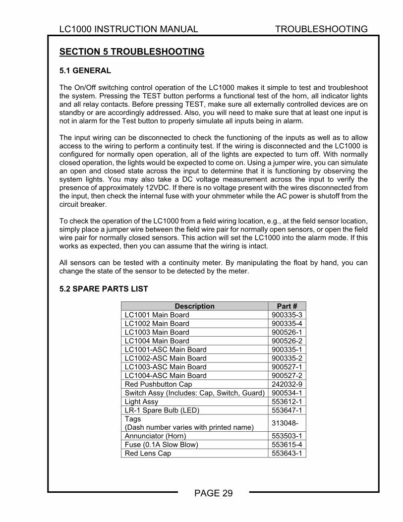
SECTION 5 TROUBLESHOOTING 5.1 GENERAL The On/Off switching control operation of the LC1000 makes it simple to test and troubleshoot the system. Pressing the TEST button performs a functional test of the horn, all indicator lights and all relay contacts. Before pressing TEST, make sure all externally controlled devices are on standby or are accordingly addressed. Also, you will need to make sure that at least one input is not in alarm for the Test button to properly simulate all inputs being in alarm. The input wiring can be disconnected to check the functioning of the inputs as well as to allow access to the wiring to perform a continuity test. If the wiring is disconnected and the LC1000 is configured for normally open operation, all of the lights are expected to turn off. With normally closed operation, the lights would be expected to come on. Using a jumper wire, you can simulate an open and closed state across the input to determine that it is functioning by observing the system lights. You may also take a DC voltage measurement across the input to verify the presence of approximately 12VDC. If there is no voltage present with the wires disconnected from the input, then check the internal fuse with your ohmmeter while the AC power is shutoff from the circuit breaker. To check the operation of the LC1000 from a field wiring location, e.g., at the field sensor location, simply place a jumper wire between the field wire pair for normally open sensors, or open the field wire pair for normally closed sensors. This action will set the LC1000 into the alarm mode. If this works as expected, then you can assume that the wiring is intact. All sensors can be tested with a continuity meter. By manipulating the float by hand, you can change the state of the sensor to be detected by the meter. 5.2 SPARE PARTS LIST
Description Part # LC1001 Main Board 900335-3 LC1002 Main Board 900335-4 LC1003 Main Board 900526-1 LC1004 Main Board 900526-2 LC1001-ASC Main Board 900335-1 LC1002-ASC Main Board 900335-2 LC1003-ASC Main Board 900527-1 LC1004-ASC Main Board 900527-2 Red Pushbutton Cap 242032-9 Switch Assy (Includes: Cap, Switch, Guard) 900534-1 Light Assy 553612-1 LR-1 Spare Bulb (LED) 553647-1 Tags (Dash number varies with printed name)
313048-
Annunciator (Horn) 553503-1 Fuse (0.1A Slow Blow) 553615-4 Red Lens Cap 553643-1
LC1000 INSTRUCTION MANUAL MAINTENANCE
PAGE 30
SECTION 6 MAINTENANCE/TESTING 6.1 CONSOLE The operation of the LC1000 lights, horn, and relays can be verified by holding down the TEST button. The TEST button causes all alarm conditions for the system to go to the alarm state. For this reason, it is best to do this with at least one alarm condition in the normal state otherwise your horn will not activate since there are no new alarm conditions detected. If the lights and horn do not activate as expected, follow the troubleshooting instructions found in Section 5. There are no consumables for the LC1000 therefore no parts need to be changed on a regular basis. Refer to section 5 for a list of service parts available to repair the LC1000. 6.2 SENSORS The sensors themselves cannot be tested from the front panel of the LC1000. Instead you must remove the sensor and manipulate each float by hand to simulate an alarm condition. The only exception to this rule is in the case of an LS600 equipped with a test lever. This test lever allows for the testing of the uppermost float, typically used as the overfill protection. See Bulletin 193 for details on the LS600 Series sensors.
WARNING
Testing MUST be done by qualified personnel familiar with local wiring codes and explosion hazard electrical safety practices. FAILURE TO COMPLY MAY RESULT IN PERSONAL INJURY, PROPERTY LOSS AND EQUIPMENT DAMAGE.
It is generally considered good practice to ensure that your system is fully operational on an annual basis. For thicker or more viscous liquids, you may want to inspect the system more frequently to confirm that no product has built up on the sensor so as to interfere with its proper operation. Your local regulations may require testing based on a different schedule so consult with your regulator/inspector for the frequency of testing needed for your application.

WARRANTY
We warrant that our tank gauges, if installed according to instructions will be free from defects in material and workmanship for a period of one (1) year following the date of original shipment by us. Our liability under this warranty shall be limited to, at our option, (i) repair of the defective tank gauge, (ii) replacement of the original tank gauge with new, or (iii) refund of the original purchase price; and, we shall not be liable for any labor, other installation costs, indirect or consequential damages, or other damages in connection with such gauge. This constitutes our obligation and none other stated for any purpose except the above shall apply. Contact Pneumercator for detailed warranty documentation.
REVISION 101008
Pneumercator Co. 1785 Expressway Drive North
Hauppauge, NY 11788 TEL:(631) 293-8450 FAX:(631) 293-8533
www.pneumercator.com
Distributed by: PNEUMERCATORLiquid Level Control Systems