instruction manual model 1250 atmospheric … · section 2 – operating instructions 2-1 section 2...
TRANSCRIPT

INSTRUCTION MANUAL
MODEL 1250 ATMOSPHERIC CONSISTOMETER
Revision A – November 2015 P/N: 12-0186
S/N: ____________
2001 N. Indianwood Ave. Broken Arrow, Oklahoma 74012 U.S.A.
Telephone: 918-250-7200 Fax: 918-459-0165
E-mail: [email protected] Website: http://www.chandlereng.com

Copyright 2015, by Chandler Engineering Company L.L.C. All rights reserved. Reproduction or use of contents in any manner is prohibited without express permission from Chandler Engineering Company L.L.C. While every precaution has been taken in the preparation of this manual, the publisher assumes no responsibility for errors or omissions. Neither is any liability assumed for damages resulting from the use of the information contained herein. This publication contains the following trademarks and/or registered trademarks: AMETEK, CHANDLER ENGINEERING. These trademarks or registered trademarks and stylized logos are all owned by AMETEK, Inc. All other company, product and service names and logos are trademarks or service marks of their respective owners.
TABLE OF CONTENTS T-1
Table of Contents General Information................................................................ P-1
Introduction ...................................................................................................................... P-1 Purpose and Use .......................................................................................................... P-1 Description .................................................................................................................. P-1
Features and Benefits ......................................................................................................... P-2 Specifications .................................................................................................................... P-2 Safety Requirements .......................................................................................................... P-3 Where to Find Help ........................................................................................................... P-3
Section 1 – Installation ............................................................ 1-1 Unpacking the Instrument .................................................................................................. 1-1 Utilities Required ............................................................................................................... 1-1 Tools/Equipment Required ................................................................................................ 1-1 Setting Up the Instrument .................................................................................................. 1-1
Section 2 – Operating Instructions .......................................... 2-1 Model 1250 ....................................................................................................................... 2-1 Temperature Controller ..................................................................................................... 2-2 Temperature Controller ..................................................................................................... 2-3
Set Point Control ......................................................................................................... 2-3 Ramp Rate Control ...................................................................................................... 2-3
Strip Chart Recorder ......................................................................................................... 2-4
Section 3 – Maintenance ......................................................... 3-1 Tools Required .................................................................................................................. 3-1 Strip Chart Recorder ......................................................................................................... 3-1 Cleaning and Service Tips .................................................................................................. 3-1 Calibration Procedure ........................................................................................................ 3-3 Maintenance Schedule ....................................................................................................... 3-1
Section 4 – Troubleshooting Guide ......................................... 4-1
Section 5 - Replacement Parts ................................................. 5-1
Section 6 - Drawings and Schematics ...................................... 6-1

T-2 TABLE OF CONTENTS
This page is intentionally left blank.

PREFACE P-1
General Information
Introduction This manual contains installation, operation, and maintenance instructions for the Chandler Engineering Model 1250 Recording Atmospheric Consistometer.
Purpose and Use
The Chandler Engineering Model 1250 Recording Atmospheric Consistometer is used for various tests of oil well cements as detailed in the American Petroleum Institute Specification for Materials and Testing for Well Cements - Specification 10 A/B (API Spec 10 A/B). The apparatus is used in conjunction with tests for: • Determination of Water Content of Slurry • Determination of Fluid Loss • Determination of Rheological Properties of Cement Slurries
Description
The Chandler Engineering Model 1250 Recording Atmospheric Consistometer consists of a stainless-steel water bath that houses two slurry containers. The slurry containers are rotated by engaging the pins of the lid with the slots on the rotator. The rotators are fitted with timing sprockets driven by the motor, which is factory set at 150 rpm. The belt also drives an impeller that agitates the water bath. An instrument cabinet, with a removable front panel, houses a microprocessor-based temperature controller that also serves as a digital temperature indicator. The temperature controller operates a relay that controls a 1500-watt heater. The Model 1250 includes cooling coils as a standard feature. Lighted switches that also serve as circuit breakers are installed in the front panel. The circuit breaker function of these switches eliminates the necessity for in-line fuses. The Model 1250 indicates consistency and temperature on a panel-mounted strip chart recorder. The Model 1250 also includes audible alarms that sound at preset consistency values. The alarm set points are individually adjustable on the recorder. Slurry consistency is expressed in Bearden units of consistency, Bc, where 100 Bc is equivalent to the spring deflection observed with 2,080 grams-centimeter of torque (400 grams weight) using the weight-loaded calibrating device. For further details, refer to API Spec 10 A/B. The Model 1250 is easily calibrated using the Consistency Calibration Potentiometers located on the back panel.

P-2 PREFACE
Features and Benefits • Temperature is measured accurately using a microprocessor-based temperature controller. • Rate of water bath rise can be controlled to conform with API Spec 10 A/B requirements
or other temperature gradients desired. • Stainless-steel water bath ensures long trouble-free operation in the normally corrosive
cement testing environment. • Operational simplicity provides freedom from operator error and a short training period
for new operators. • Units are designed for trouble-free oil field laboratory operation. • Direct torque spring readout permits instant determination of the slurry viscosity in
Bearden Units (Bc). • Standard deadweight calibration is both simple and rapid, aiding measurement accuracy.
(An optional calibrator unit may be purchased.) • Constant temperature is maintained by a motor-driven stirred water bath that eliminates
any hot spots on the slurry containers. • Rotational speed of the slurry container is held constant by the drive motor assembly,
which is factory set at 150 rpm. • A variable speed option is available for studies at slurry container rotational speeds other
than 150 rpm. • Internal cooling coils provide quick cooling of the slurry. • Equipped with a strip chart recorder to provide a permanent record of temperature and
viscosity. • Viscosity alarms that can be set over the range from less than 30 Bc to 100 Bc. The
alarms alert the operator that a specific viscosity has been obtained for recording data or taking other action.
Specifications
Measurement Range: 0 - 100 Bc Operating Conditions: 50°F - 120°F (10°C - 49°C) Maximum Temperature: 200°F (93°C) Input Voltage: 100–130VAC/200-240VAC, 50/60 Hz ± 10% Input Power: 2 kVA Heater Wattage: 1500 W Dimensions: 25” (64cm) high x 15.5 (39cm) wide x 18” (45cm) deep Shipping Dimensions: 29” (74cm) high x 20” (51cm) wide x 29” (74cm) deep Net Weight: 110 lbs (50 kg) Shipping Weight: 190 lbs (86 kg) Slurry Container Volume: 28 cubic inches (470 ml) Slurry Cup Rotational Speed: 150 rpm supplied as standard Option D-1 provides variable speeds from 50 - 200 rpm

PREFACE P-3
Safety Requirements
READ BEFORE ATTEMPTING OPERATION OF INSTRUMENT The Chandler Engineering Model 1250 Recording Atmospheric Consistometer is designed for operator safety. Any instrument that is capable of high temperatures should always be operated with CAUTION!! To ensure safety: • Locate the instrument in a low traffic area. • Post signs where the instrument is being operated to warn non-operating personnel. • Read and understand instructions before attempting instrument operation. • Observe caution notes! • Observe and follow the warning labels on the instrument. • Never exceed the maximum temperature rating of the instrument. • Due to high temperatures, be careful not to touch the water bath tank during operation. • Always disconnect main power to the instrument before attempting any repair. • Turn off the heater at completion of each test. • When removing the slurry containers, use gloves to protect against high temperatures. • Appropriately-rated fire extinguishers should be located within close proximity. Before attempting to operate the instrument, the operator should read and understand this manual.
Where to Find Help In the event of problems, contact your local sales representative or Chandler Engineering: • Telephone: 918-250-7200 • Fax: 918-459-0165 • E-mail: [email protected] • Website: www.chandlereng.com Instrument training classes are also available.

P-4 PREFACE
This page is intentionally left blank.

SECTION 1 – INSTALLATION 1-1
Section 1 – Installation
Unpacking the Instrument Verify all parts listed on the packing slip have arrived with the instrument. If parts are missing, contact Chandler Engineering immediately.
Utilities Required 100-130VAC/200-240VAC 20/15 A 50/60 Hz Water supply Drain
Tools/Equipment Required Basic hand tools
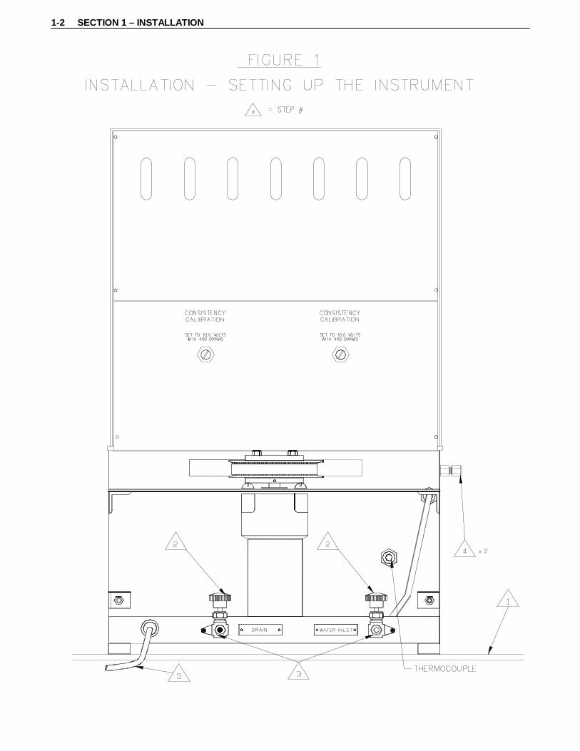
Setting Up the Instrument Refer to Figure 1 for the following steps: 1. Place the instrument on a sturdy, level table. 2. Close the supply and drain valves by turning the knobs counterclockwise. 3. Connect the water supply and drain lines. 4. Connect cooling coils to a cold water source and drain, if so desired. Cooling coil use is
optional. Either connection can be used for the inlet or outlet. 5. Connect power cord to the correct voltage source. Note: To prevent shock hazard, connect the instrument to an electrical outlet using a three-
prong socket to provide positive ground.
1-2 SECTION 1 – INSTALLATION

SECTION 2 – OPERATING INSTRUCTIONS 2-1
Section 2 – Operating Instructions
Model 1250 As described in Calibration Procedure, found in Maintenance - Section 3, the paddle should be checked to ensure that it is not bent or does not rub the inside of the slurry container. Refer to Figure 2 for the following steps unless otherwise noted: 1. Remove the slurry container. 2. Open the water supply valve by turning the knob counterclockwise and fill the bath
until it is 1/2” (12.5mm) below the brass rotating sleeve (Refer to Section 1 – Installation; Figure 1).
3. Close the water supply valve by turning the knob clockwise when the appropriate water level is obtained (Refer to Section 1 – Installation; Figure 1).
4. Prepare sample and fill the slurry container as detailed in API Spec 10 A/B. 5. Attach the container lid to the slurry container. Caution: Line up the pointed end of the paddle to the center pivot hole at the bottom
of the slurry container to ensure smooth rotation. 6. Install the slurry container in the instrument. Be sure the bottom roll pin on the
container lid fits into the brass rotator sleeve slots. 7. Turn the container lid until the torque bar fits into the anchor stop. 8. Verify the Mic plug is connected to the appropriate socket located on the front panel. 9. Turn the master switch on. 10. Use the temperature controller to set the desired temperature or heating profile. Refer
to Set-point Control in the Temperature Controller section for further details. 11. Turn on the motor switch. 12. Turn on the heater switch. 13. An alarm will sound upon completion of the test (the alarm is factory set to 100 Bc
and will independently sound for each cylinder). Caution: Remove the slurry on or before 100 Bc of torque to prevent shearing of the shear
pin or slippage of the indicator caused by forcing it against the stop. 14. After completion of the test, the alarm will sound. Turn off the motor switch. 15. Remove the slurry container. If only one slurry container is removed, the motor
switch can be turned on to finish the other test if necessary. Note: When the slurry container is removed or the potentiometer cable is unplugged,
the buzzer will stop. 16. Before draining the water, turn off the heater and power switches. 17. Open the drain valve by turning the knob counterclockwise to remove the water from
the tank (Refer to Section 1 – Installation; Figure 1). 18. Close the drain valve by turning the knob clockwise (Refer to Section 1 – Installation;
Figure 1).

2-2 SECTION 2 – OPERATING INSTRUCTIONS

SECTION 2 – OPERATING INSTRUCTIONS 2-3
Temperature Controller
FIGURE 3
Set Point Control
The temperature controller is used to control the temperature of the water bath. To set the water bath temperature, use the “Up/Down” arrow buttons to change the set-point temperature value. This will heat the bath as fast as possible to the set point. The “OP1” light will turn on indicating the controller is operating. To disable the temperature controller press the “Down” arrow button and set the controller to “0.0.” The “OP1” light will shut off.
Ramp Rate Control
To heat using a ramp rate, press the page button until the “SP” list (set point list) is displayed. Press the scroll button until the “SPrr” (set point ramp rate) is displayed, press the “Up/Down” arrow buttons to set the desired ramp rate (degrees/minute). Press the page button to return to the normal display. Using the “Up/Down” arrow buttons, adjust to the final temperature desired. Both the “RUN” and “OP1” lights will turn on. To disable the heater, press the “PAGE” button to “SP” list, scroll to “SPrr,” and adjust the ramp rate to “OFF.” Press the “PAGE” button to advance to the normal display and adjust the set point to “0.0” using the “Down” arrow button. The “RUN” and “OP1” lights will shut off.

2-4 SECTION 2 – OPERATING INSTRUCTIONS
Strip Chart Recorder Refer to the accompanying instruction manual for the strip chart recorder for operation.

SECTION 3 – MAINTENANCE 3-1
Section 3 – Maintenance
Tools Required Adjustable wrench Phillips screwdriver
Strip Chart Recorder Refer to the accompanying instruction manual for the strip chart recorder regarding any maintenance instructions.
Cleaning and Service Tips The slurry cup rotators are moved on fluorocarbon polymer bearings that have low friction resistance and require only occasional lubrication. It is recommended that the rotators be examined periodically and lubricated with a light lubricating oil. Refer to Figure 3 for the following steps: 1. Disconnect electrical power. 2. Remove back protective cover plate. 3. Loosen bolts on motor mounting bracket. 4. Push motor forward. 5. Remove belt from motor timing sprocket. 6. Remove the ten (10) outer screws on the deck cover, remove the entire assembly from
the water bath, and set it on blocks to prevent damage to the rotators. 7. Remove the four (4) inner screws on the deck and remove the top plate from the
bearing housing. 8. Loosen and rotate retaining tabs securing the rotators in the bearing housing. 9. Pull rotators. (CAUTION: Watch for loose bearings when rotators are removed!) 10. Clean rotators, bearings and bearing assembly. 11. Place bearings in bearing assembly. (CAUTION: Use 38 bearings per rotator!) 12. Apply oil generously to bearings. 13. Re-assemble instrument. 14. Pull motor back only enough to prevent belt slippage. Allow approximately 1/2"
(12.5mm) slack in drive belt to prevent excessive side thrust to bearings. (CAUTION: Do not over-tighten belt!)

3-2 SECTION 3 – MAINTENANCE
FIGURE 4 - CLEANING AND SERVICE TIPS

SECTION 3 – MAINTENANCE 3-3
Calibration Procedure Before calibration and operation of the instrument, the paddle should be tested for excessive friction by running the slurry container without cement inside. If the paddle is bent so that it rubs on the side, appreciable movement will be shown on the strip chart recorder. The bearings in the slurry-indicating lid should be checked for excessive friction. Any abnormality should be corrected before proceeding with the instrument calibration. Calibration and operation of the instrument is described in API Spec 10 A/B. This instrument is equipped with a calibrating spring and can be calibrated using the calibration device. The calibration device can be purchased separately. The roller located on the side of the calibration device is raised to a position so that the cord is level with the lid. Refer to Figure 4 for the following steps unless otherwise noted: 1. Place the container lid on the calibration assembly. 2. Place the cord counterclockwise around the lid and attach 400 grams of weight. 3. Connect the wires to the appropriate pins located on the container lid. Position the wires
so they don’t restrict the rotation of the container lid. 4. Pull the weight down slightly and release a few times to obtain an average reading. 5. Adjust the Consistency Calibration Potentiometer located on the back of the instrument
(Refer to Section 1 – Installation; Figure 1) until the recorder reads 100 Bc. 6. Repeat steps 1 through 5 for the other slurry container if necessary. Note: The Consistency Calibration Potentiometers are located on the back panel of the
instrument and directly behind the appropriate slurry containers.

3-4 SECTION 3 – MAINTENANCE

SECTION 3 – MAINTENANCE 3-1
Maintenance Schedule
MAINTENANCE SCHEDULE MODEL 1250 ATMOSPHERIC CONSISTOMETER
COMPONENT EACH TEST MONTHLY 3 MONTHS 6 MONTHS ANNUALSlurry Cup Disassemble
Clean Inspect
Potentiometer Mechanism
Clean Inspect
Calibrate
Drive Motor Check Speed
Rotators and Bearings
Clean Lubricate
Temperature Controller
Calibrated By Qualified Factory Service Technician
Thermocouple Calibrated By Qualified Factory Service Technician
This maintenance schedule applies to normal usage of two tests per day. Detailed procedures for these operations are contained in your manual. Per API Specifications

3-2 SECTION 3 – MAINTENANCE
This page is intentionally left blank.

SECTION 4 – TROUBLESHOOTING GUIDE 4-1
Section 4 – Troubleshooting Guide
Problem Solution Unit will not power-up.
1. Check main power.
Drive motor is inoperative.
1. Replace motor controller fuse on the motor speed
control board. 2. Clean and lubricate the bearings and rotators. 3. Replace brushes in the motor. 4. Replace the motor speed control board. 5. Replace motor.
Heater system is inoperative.
1. Replace solid state relay. 2. Replace temperature controller. 3. Replace heater.
Timer is inoperative.
1. Replace timer.
Chart is hard to read.
1. Replace pens.

4-2 SECTION 4 – TROUBLESHOOTING GUIDE
This page is intentionally left blank.

SECTION 5 – REPLACEMENT PARTS 5-1
-1250-REPL_PARTS REV C
Section 5 - Replacement Parts
Part Number Description 07-0176 Thermocouple Assembly 07-0505-03 Potentiometer Calibrating Device Assembly (Optional) 12-0021 Paddle Assembly 12-0023 Container Assembly 12-0031 Cross Bar Support 12-0033 Heater Assembly, 220V 12-0044 Bearing Housing Assembly 12-0045 Rotator Assembly 12-0047 Sprocket, Idler and Stirrer Assembly 12-0048 Impeller and Shaft Assembly 12-0057 Heater Assembly, 110V 12-0059 Internal Cooling Coil 12-0082 Container Lid Assembly - Potentiometer Type 12-0091 Anchor Stop Assembly 12-0126 Cabinet and Tank Assembly 12-0176 Timing Belt Sprocket, Coated 12-0177 Split Bushing, Coated 7080 Temperature Controller C07882 DC Power Supply C07952 Potentiometer, 100 Ohm, CTS, 5W, 500 VDC C09286 Motor, Gear, DC (S/N 1254 and above) C09287 Controller, DC Control, Model 0865 (S/N 1254 and above) C10647 Recorder, 3 Pen C10828 Recorder, 3 Pen, Red C10829 Recorder, 3 Pen, Green C10830 Recorder, 3 Pen, Blue C10832 Recorder Paper P-0025 Cable Clamp P-0417 Terminal Block, 6 Conductor P-0424 Terminal Block, 2 Conductor P-0655 Glider Foot P-1233 Rubber Foot P-1418 Socket, 3 Contact P-1500 Needle Valve P-1648 Set Collar P-1649 Timing Belt P-1653 Terminal Strip P-1698 Nylon Bearing Balls P-1938 Step-down Transformer, 220 VAC P-2005 Terminal Jumpers P-2702 Resister,2K Ohm,8W,5%,WW P-2948 Variable Speed Control Knob P-3255 Motor, Gear, DC,1/17HP, 208RPM (S/N 1253 and below) P-3256 Control, Motor Speed (S/N 1253 and below)

-1250-REPL_PARTS REV C
Part Number Description P-3330 Solid State Relay P-3387 Circuit Breaker Switch, 16A, 110 VAC P-3388 Circuit Breaker Switch, 10A, 220V P-3389 Circuit Breaker Switch, 8A, 220V P-3390 Circuit Breaker Switch, Motor, 3A,110 VAC
To ensure correct part replacement, always specify Model and Serial Number of instrument when ordering or corresponding.

SECTION 6 – DRAWINGS AND SCHEMATICS 6-1
-????-DWGS REV A
Section 6 - Drawings and Schematics
Drawing Number Description 07-0505-03 Potentiometer Calibration Device Assembly 12-0082 Container Lid Assembly 12-0134 Model 1250 Atmospheric Consistometer 12-0158 Wiring Schematic, 200-240VAC 12-0178 Wiring Schematic, 100-130 VAC


CHANDLER ENGINEERING
CHANDLER ENGINEERING CO.

ZONE APPROVEDDATEDESCRIPTIONREV.
REVISIONS
SS/TC4/14/09ECN# T2247, CREATE IN SOLIDWORKSH
ITEM NO. PART NUMBER Description exploded/QTY.
1 12-0090 WIPER 12 P-0844 PIN,SHEAR,BRS,0.035x0.50L 13 P-1588 BEARG,BALL,.393X1.181X.354 14 P-1642 RING,RTNG,INT,1.319OD 15 P-1683 PIN,ROLL,.1875X.75L 26 P-1809 27 P-2046 SPRING, CONTACT 28 07-0451 WASHER, FIBRE 29 12-0015 SYNTHANE,RND,3.50X1.50L,GR LE 1
10 12-0083 FRAME 111 12-0084 SHAFT, TORQUE 112 12-0085 CALIBRATION SPRING COLLAR 113 12-0086 SPACER-BEARING 114 12-0087 COVER 115 12-0088 CALIBRATION SPRING RETAINING PIN 116 12-0089 TORQUE BAR 117 H-5003 SCREW,SKHSS,SS,5-40X0.187,CUP 118 H-8007 SCREW, 8-32 X 3/16 LG. BNDG HD PHILLIPS 219 H-6035 SCREW, SET, 6-32 X 1/4 LG. CONE POINT 120 H-8022 SCREW,BHMS,SS,8-32X1.000,PHIL 321 H-25-002 NUT,SST,HX,10-32 222 07-0064 SPRING,CALIBRATION 123 07-0058-1 ASSY,RESISTOR,POT MECH 1
19
9
55
11
20
14
21
1
21
23
615
13
17
10
18
8
16
6
22
12
4
3
2
4/14/09
TC 4/15/09JJM 4/15/09
D
C
B
AA
B
C
D
12345678
8 7 6 5 4 3 2 1
E
F
E
F
ENGR.:
SS
SCALE: 1:8 SHEET: 1 of 1
320.0050.0100.030
3 PLACE2 PLACE1 PLACE
ANGLESSURF. FINISH
TOLERANCES:DIMENSIONS IN INCHES
UNLESS OTHERWISE SPECIFIED
DATEAPPROVALS
DRAWN:
CHECKED:
USED ON
BREAK SHARP EDGES, DEBURR
NEXT ASSY
QTY. REQD. PARTS LIST
CHANDLER ENGINEERING
1/2
H12-0082DREV.DWG NO.
TITLE
SIZE
COPYRIGHT BY CHANDLER ENGINEERING COMPANY, LLC
. .
APPLICATION
TITLE BLOCK REV: 2.0
THIS DOCUMENT AND THE DRAWINGS AND TECHNICAL DATA CONTAINED HEREON ARE THE PROPERTY OF CHANDLER ENGINEERING COMPANY, LLC REPRODUCTION OR DISSEMINATION IN ANY FORM EXCEPT AS EXPRESSLYAUTHORIZED BY THE OWNER IS FORBIDDEN. THE HOLDER AGREES TO RETURNTHIS DOCUMENT TO THE OWNER ON DEMAND.
LID ASSEMBLY
SPRING ORIENTATION(CLOCKWISE ROTATION)
NOTE: STAMP ON LID ASSY.
BK
Y
BL
SECTION A-A SCALE 1 : 1

CHANDLER ENGINEERING


CHANDLER ENGINEERING

AEROSPACE & DEFENSE
2001 North Indianwood Avenue, Broken Arrow, OK 74012 Phone: 918-250-7200 Fax: 918-459-0165
© 2008, by AMETEK, Inc. All rights reserved. e-mail: [email protected] www.chandlereng.com
Model 1200 & 1250ATMOSPHERIC CONSISTOMETERSA Critical Tool for Oil Well Drilling and Cementing
The Models 1200 and 1250 are specifically designed to be a simple and accurate means to prepare cement slurries for the testing of rheological properties, fluid loss and various other properties in strict compliance with API 10 A/B. These instruments are used daily in laboratories involved in: oil well cement research, research and testing of cement additives, cement quality assurance and the research and field laboratories of well service companies.
These instruments increase lab productivity and save valuable technician time by simultaneously conditioning two slurry samples for subsequent testing.
Operational Simplicity
These instruments are simple to operate with all of the controls conveniently located on the front panel. The unit is designed so that closure, heating and pressurization can be achieved quickly.
The slurry cup drive automatically rotates the cup at the required, standard rate of 150 rpm. Accurate temperature control of the stainless steel water bath is maintained by a programmable temperature controller as well as a motor-driven stirring mechanism in the water bath that eliminates hot spots on the slurry cups.
Indicators for each viscosity and the water bath temperature are readily visible on the front panel of the unit. The Model 1250 adds a strip chart recorder which provides a permanent record of temperature and viscosity measurements.
Upon completion of slurry conditioning, cooling coils can be used to quickly lower the temperature of the slurry for safer handling.
FEATURES
3 Two Conditioning Cups
3 Consistency Alarms
3 Accurate Temperature Control
3 Internal Cooling Coils
3 Stainless Steel Water Bath
3 Built-in Chart Recorder on Model 1250
3 150 rpm Slurry Cup Drive

Printed in the U.S.A. © 2008, by AMETEK, Inc. All rights reserved. XM808PDF (360000)
2001 North Indianwood Avenue, Broken Arrow, OK 74012 Tel: +1 918-250-7200 Fax: +1 918-459-0165e-mail: [email protected] www.chandlereng.com
Houston Sales and Services4903 W. Sam Houston Parkway, N., Suite A-400, Houston, TX 77041 Tel: +1 713-466-4900 Fax: +1 713-849-1924
Model 1200 & 1250
Specifications
Maximum Temperature200ºF (93ºC)
Maximum Pressure Atmospheric pressure
Heater Power 1500 Watts
Environmental Operating Temperature 41°F - 104ºF (5ºC - 40ºC)
UtilitiesMains 100 - 130 VAC, 16A, 50/60 Hz, 1 Phase208 - 240 VAC, 8A, 50/60 Hz, 1 Phase
Water 20-100 psi (140-689 kPa); nominal flow 2 Lpm
Slurry Cup Rotation Speed150 rpm
Slurry Cup Volume28 cubic inches (470 mL)
Consistency Range 0 to 100 Bc (Bearden Units)
Data Acquisition Model 1250 includes a strip chart recorder which tracks the water bath temperature and the consistency of each slurry under test
Physical DimensionsDimensions (h x w x d) 25 in x 15.5 in x 18 in (64 cm x 39 cm x 45 cm)
Weight110 lb (50 kg)
Shipping InformationDimensions 29 in x 20 in x 29 in (74 cm x 51 cm x 74 cm)
Weight 190 lb (86 kg)
ComplianceAPI Spec 10A (ISO 10426-1) CE (Model 1200 only)
Manufacturer’s specifications subject to change without notice
R0109.002
Revision 1: August 6, 2014


