instruction manual january r mtl700 - mtl instruments mtl700 and 700p range of shunt-diode safety...
TRANSCRIPT

MTL700 MTL700 and 700P range of shunt-diode safety barriers
Instruction manual MTL intrinsic safety solutions
January 2017 INM700 Rev 12

Declaration of ConformityA printed version of the Declaration of Conformity has been provided separately within the original shipment of goods. However, you can find a copy of the latest version at:http://www.mtl-inst.com/certificate
ii

© 2017 Eaton Electric Limited. All rights reserved.
INM700 Rev 12 iii
Contents Page
1 INTRODUCTION ...................................................................................................................................... 1
2 DESCRIPTION .......................................................................................................................................... 1
3 BARRIER SPECIFICATIONS ................................................................................................................. 1 3.1 The MTL700 and 700P range ................................................................................................................................... 1 3.2 General specifications ............................................................................................................................................. 2 3.3 Additional specifications .......................................................................................................................................... 2 3.4 Common specification ............................................................................................................................................. 3 3.5 Approvals .............................................................................................................................................................. 5 3.6 Enclosure specifications............................................................................................................................................ 6
4 SAFETY CONDITIONS ................................................................................................................... 6 4.1 General safety requirements ..................................................................................................................................... 6 4.2 Safety checks ......................................................................................................................................................... 6
5 MOUNTING THE BARRIERS (ENCLOSED SYSTEMS) ..........................................................................6 5.1 Fitting the barriers into the enclosure .......................................................................................................................... 7 5.2 Mounting the enclosure ............................................................................................................................................ 7
6 MOUNTING THE BARRIERS (UNENCLOSED SYSTEMS) ..................................................................... 9 6.1 The MTL700 and 700P range of accessories range ...................................................................................................... 9 6.2 Constructing the installation .....................................................................................................................................10 6.3 Using SMC7 surface mounting clips..........................................................................................................................12 6.4 MK2 mounting kits .................................................................................................................................................12 6.5 MK5, MK12 and MK20 mounting kits ......................................................................................................................12
7 WIRING INSTALLATION ................................................................................................................... 13 7.1 Glanding cables into enclosures ...............................................................................................................................13 7.2 Earthing the barriers ...............................................................................................................................................13 7.3 Connecting non-hazardous (safe) area cables to barriers .............................................................................................14 7.4 Connecting hazardous-area cables to barriers...........................................................................................................14 7.5 Cable parameters for MTL700 range – BASEEFA(ATEX) & FM ...................................................................................... 16 7.6 Entity concept parameters for MTL700 range – FM .................................................................................................... 17 7.8 Entity concept parameters for MTL700P range – FM .................................................................................................. 18 7.9 Final check ............................................................................................................................................................19
8 MAINTENANCE ..................................................................................................................................... 19 8.1 Routine inspection ..................................................................................................................................................19
9 FAULT-FINDING ................................................................................................................................................. 20 9.1 Power supply check ................................................................................................................................................20 9.2 Barrier resistance test (not MTL702, 705, 706, 707, 707P and 708) ............................................................................20 9.3 Earth faults ............................................................................................................................................................20 9.4 Faults between barrier channels ...............................................................................................................................21
10 THERMOCOUPLE AND RTD TESTS ................................................................................................ 21 10.1 Thermocouple circuit testing .....................................................................................................................................21 10.2 Resistance thermometer detector circuit testing ............................................................................................................21
continued overleaf
DECLARATION OF CONFORMITY .................................................................................................. ii

INM700 Rev 12 iv
CONTENTS PAGE
11 BARRIER TESTS .......................................................................................................................... 21 11.1 Multimeter tests ......................................................................................................................................................22 11.2 Constant-current tests ..............................................................................................................................................22 11.3 Tests for the MTL702 ...............................................................................................................................................22 11.4 Tests for the MTL705 and 706 .................................................................................................................................22 11.5 Tests for the MTL707 and 707P ................................................................................................................................22 11.6 Tests for the MTL708 ...............................................................................................................................................22 11.7 Test tables .............................................................................................................................................................22
APPENDIX A: ATEX certification information.............................................................................................. 27

INM700 Rev 12 1
MTL700 range of shunt-diode safety barriers
MTL700 & 700P range SHUNT-DIODE SAFETY BARRIERS
1 INTRODUCTION This instruction manual contains the information necessary to install, maintain, fault-find and test MTL700 and MTL700P range of shunt- diode safety barriers. Section 4 of the manual contains a checklist which highlights all the important safety factors that should be considered when using MTL700 and 700P range of barriers to interface between non-hazardous (safe) and hazardous areas. All users should read this section, and particularly the checklist, before commencing work on the barrier installation.
For further applicational information concerning the theory and use of shunt-diode safety barriers, users are recommended to read the following publications:
Application Note AN9003, A user’s guide to intrinsic safety; Application Note AN9007, A user’s guide to shunt-diode safety barriers (MTL700 range); MTL Intrinsic safety catalogue covering MTL700 and 700P range of barriers, and enclosures, parts & accessories; CD700 customer drawings, for additional installation informa- tion.
These publications and a comprehensive selection of our technical papers (TPs) can be obtained from the company’s Publicity department on request: TP1064, 1076, 1082, 1083 and 1106 are particularly relevant. Copies of the apparatus and system certificates issued by the various certifying authorities are also available.
2 DESCRIPTION MTL700 and 700P range of shunt-diode safety barriers are 1-channel or 2-channel devices that employ intrinsically safe techniques to allow electrical signals to be passed between non-hazardous (safe) and hazardous areas. They achieve this by limiting the transfer of energy in one direction to a level that cannot cause ignition of explosive atmospheres. Barriers that are connected in series with lines going to a hazardous area will protect wiring and equipment in that area from any faults occurring in the non-hazardous (safe) area, thus permitting a wide range of measurement and control operations to be undertaken safely.
Applications of MTL700 and 700P range of barriers include the protection of installations containing non-energy storing
Uncertified devices such as switches, thermocouples, resistive sensors, photocells and LEDs, or separately certified ‘energy storing’ apparatus, for example ac sensors, transmitters and I/P converters. The barriers also enable maintenance work or calibration to be carried out without further precautions, and they permit non-hazardous (safe) area equipment to be worked on safely as and when necessary, with the minimum of restriction.
A range of five polycarbonate enclosures is available to provide environmental protection for barriers where required, and a Type N approved steel enclosure also is available to permit the barriers to be installed in Zone 2 areas. Enclosures and other accessories are fully described in this manual.
3 BARRIER SPECIFICATIONS 3.1 The MTL700 and 700P ranges The range consists of a carefully tailored range of application-orientated models, most polarised positively but some negatively and some non- polarised. There is also a ‘dummy’ barrier. Basic circuits, specifications and approvals for each model are given in sections 3.2 to 3.5.
In 1992/3 a range of MTL700P higher-power barriers was introduced and is listed under 3.2 General specifications. The MTL700P range of barriers complement similarly numbered MTL700 range of barriers but deliver more power into hazardous areas. The range covers two distinct types: one type is designed for IIC gas group areas while the other is for IIB gas groups. The additional power available with the IIC units is made possible by a change in the BSI’s interpretation of the requirements of EN 50020 which brings it into line with other European authorities. It also corresponds with the requirements of North American standards.
The MTL700P barriers are mechanically identical to the MTL700 range of barriers and are therefore compatible with all MTL700 range accessories.
Seven ‘key’ MTL700 range of models are highlighted in the sales literature as meeting most process control requirements. These models and their applications are listed in table 1. The literature also cross refers to MTL700P range of barriers where a higher-power barrier application may be required.

INM700 Rev 12 2
To minimise spares stocks and simplify maintenance procedures it is worth noting that the ‘key’ barriers can often be used in place of other models: the MTL706+ can replace the MTL702+ provided that the transmitter is certified for a Umax:in of at least 28V and the transmitter and its lines require no more than 15V to operate. Both are nearly always the case. The MTL706+ consumes less current than the MTL702+ and allows 2-way communication with most ‘smart’ transmitters. Note that when undertaking the MTL702/706 substitution, terminals 3 and 4 of the MTL706 are reversed in polarity to those of the MTL702.
The MTL707+ can replace the MTL787+ provided only that the small extra voltage drop can be accepted. It accepts power supplies up to 35V without blowing its fuse. The MTL708+ can replace the MTL728+ with the same provisos and advantage, and also that the 1mA leakage current through the 708’s electronic protection network is acceptable.
The MTL787S can always replace the MTL787+ and drops 1.5V less at 20mA. Also, under most circumstances it can replace the MTL788+ for use with 2-wire, 4/20mA transmitters.
Table 1: Key barriers summarised
TYPE APPLICATION KEY BARRIER Analogue input (low-level)
Resistance temperature detectors Thermocouples, ac sensors
755ac 760ac
Analogue output
Controller outputs, one line earthed Controller outputs, neither line earthed
728+ 787S+
dc power supply 26.0V 20–35V
Analogue input (high-level)
Transmitters, 2-wire, 4/20mA 787S+ 706+ Digital (on/off) input
Switches 787S+ 707+ Digital (on/off) output
Solenoids, alarms, LEDs 728+ 708+
Table 2: Patents issued to MTL700 and 700P range of barriers
BARRIER UK PATENT USA PATENT
MTL706+ 2205699 4967302MTL707+ 2245439 -
and 2210521 MTL708+ 2210521 - MTL787S+ 2210522 4860151 MTL707P+ 2210521 4860151
and 2210522 MTL787SP+ 2210522 4860151
3.2 General specifications 3.2.1 Terminology (Notes 1 to 7 in tables 3 and 4) 1 Safety description. The description of a barrier, eg, ’28V
300Ω 93mA’ refers to the maximum voltage of the terminating Zener or forward diode while the fuse is blowing, the minimum value of the terminating resistor and the corresponding maximum short-circuit current. It is an indication of the fault energy that can be developed in the hazardous area – not the working voltage or end-to-end resistance.
2 Polarity. Barriers are polarised ‘positive’ (+), ‘negative’ (–), or ‘non-polarised’ (ac). Polarised barriers accept and/or deliver non-hazardous (safe) area voltages of the specified polarity only. Non-polarised barriers support voltages of either polarity applied at either end.
3 End-to-end resistance. This is the resistance between the two ends of a barrier channel at 20°C, ie, of the resistors and the fuse. If series diodes or transistors are present, their voltage drop (transistors ON) is quoted in addition.
4 Working voltage (Vwkg). This is the greatest steady voltage, of appropriate polarity, that can be applied between the non-haz- ardous (safe) area terminal of a ‘basic’ barrier channel and earth at 20°C for the specified leakage current, with the hazardous- area terminal open circuit.
5 Maximum voltage (Vmax). This is the greatest voltage, of appropriate polarity, that can be applied continuously between the non-hazardous (safe) area terminal of any barrier channel and earth at 20°C without blowing the fuse. For ‘basic’ barriers, it is specified with the hazardous-area terminal open circuit; if current is drawn in the hazardous area, the maximum voltage for these barriers may be reduced. The ‘ac’ channels of ‘basic’ bar- riers and most channels of overvolt-protected barriers withstand voltages of the opposite polarity also – see circuit diagrams.
6 Fuse rating. This is the greatest current that can be passed con- tinuously (for 1000 hours at 35°C) through the fuse.
7 Star connection. In star-connected barriers, the two channels are interlocked such that the voltage between them cannot exceed the working voltage, Vwkg.
8 UM (not shown on the tables). UM defines the maximum voltage that can be applied to the non-intrinsically safe connection facili- ties of associated apparatus without invalidating intrinsic safety. For all MTL700/700P barriers, UM is 250V rms or dc with respect to earth.
3.3 Additional specifications 3.3.1 MTL702 additional specification Supply voltage
20 to 35V dc, positive w.r.t. earth Voltage available for transmitter and lines (at 20mA)
Vsupply minus 8V, limited at 16V Voltage available for load (at 20mA)
Vsupply minus 5V Load resistance
850Ω maximum Output impedance to load
>1MΩ Calibrated accuracy (at 20°C with 250Ω load)
0.05% of maximum output, including non-linearity and hysteresis Zero temperature drift
<0.005% of maximum output per °C Span temperature drift
<0.005% of maximum output per °C Supply current
8 to 40mA + 10mA maximum at 20V 8 to 40mA + 20mA maximum at 35V
3.3.2 MTL706/705 additional specification Supply voltage
20 to 35V dc, positive w.r.t. earth Output current
MTL706: 4 to 20mA MTL705: 0 to 20mA
60mA max 1 +35V max.
100mA
Current
mirror
4/20mA +Vref
Regulate 4/20mA 3
50mA +
Tx
50mA 2
850n max.
4 0V
Figure 1: MTL702 basic circuit

INM700 Rev 12 3
25.0
Hazardous area terminals
7.5 11.5 7.5
9.0
Non-hazardous (safe) area
terminals 2 1
61.5
49.2
85.0 93.5
14.2
Figure 5: Barrier dimensions in mm
40mA max +35V max.
1
50mA
Current limit
Regulate Negative
4/20mA 4/20mA 3
50mA 50mA 2
Tx +
250n ±5%
0V
Figure 2: MTL706 basic circuit
3 Current
limit
1
50mA
1 mA max
+35V max
i out
4 50mA 2
Figure 3: MTL707 basic circuit (see Table 4 for MTL707P basic circuit)
Current
50mA +35V max
LED, alarm,
solenoid, etc
i out 1 mA max
4 2
Figure 3: MTL708 basic circuit
Voltage available for transmitter and lines 15V minimum at 20mA with 22V supply 15.5V typical at 20mA with 24V supply Note: voltages are negative w.r.t. earth
Load resistance MTL706: 250Ω ±5% MTL705: 300Ω (can be greater if reduced transmitter voltage is acceptable)
Accuracy ±2µA under all conditions
Supply current 35mA typical at 20mA with 24V supply 40mA maximum at 20mA with 35V supply
3.3.3 MTL707/707P additional specification Supply voltage (Vs)
10 to 35V dc, positive w.r.t. earth Output current (Iout)
Up to 35mA available Maximum voltage drop (at 20°C, current not limited)
MTL707 Iout x 370Ω + 1.5V, terminals 1 to 3 Iout x 50Ω + 2.1V, terminals 4 to 2 MTL707P Iout x 200Ω + 0.2V, terminals 1 to 3 Iout x 18Ω + 1.3V, terminals 4 to 2
Supply current MTL707 Iout + 1mA max, Vs <26V Limited at 50mA, Vs >28V or low load resistance MTL707P Iout + 2mA max, Vs <25V Limited at 50mA, Vs >28V or low load resistance
3.3.4 MTL708 additional specification Supply Voltage (Vs)
10 to 35V dc, positive w.r.t. earth Output current (Iout)
Up to 35mA available Maximum voltage drop (at 20°C, current not limited)
Iout x 370Ω + 1.5V, terminals 1 to 3 Supply current
Iout + 1mA maximum, Vs <26V Limited at 50mA, Vs >28V or low load resistance
3.4 Common specification Ambient temperature and humidity limits
–20°C to +60°C continuous working–40°C to +80°C storage5 to 95% RH
Leakage current For ‘basic barriers’ with a working voltage of 5V or more, the leakage current decreases by at least one decade/volt reduction in applied voltage below the working voltage, over two decades. For the MTL755 it decreases by at least one decade for a 0.4V reduction in applied voltage.
Terminations Terminals accommodate conductors up to 4mm2 (12AWG) Hazardous-area terminals are identified by blue labels
Colour coding (barrier top) Grey: Non-polarised Red: Positive polarity (and MTL791) Black: Negative polarity Black (red label for safe area terminals):
positive supply, negative to transmitter (MTL706) White: Dummy barrier (MTL799)
Weight 125g approximately
Mounting and earthing By two integral M4 x 9 tin-lead plated steel fixing studs and stainless steel self-locking nuts (provided)
3 4 2
1

INM700 Rev 12 4
Table 3: Basic circuits and specifications for MTL700 range of barriers (for notes 1 to 7 see 3.2.1 Terminology)
Model No.
MTL
1 Safety description
V Ω mA
2 Polarities available
+ – ac
Application Basic circuit
Hazardous Safe
Max. end 3 -to-end
resistance Ω
4 Vwkg
10(1)µA V
5 Vmax
V
6 Fuse
rating mA
702
†705 706 707
708
25
28 28 28 28 28
200
300 300 300
diode 300
125
93 93 93 –
93
√
√ √ √
√
Transmitters
Transmitters Transmitters
Switches
Solenoids, alarms, LEDs
See 3.3 Additional
specification
–
– – – – –
–
– – – – –
35
35 35 35 –
35
See 3.3
Additional spec.
50 50
710 10 50 200 √ √ √ 6V dc & 4V ac systems 3 1 85 6.0 6.9c 50715 15 100 150 √ √ 12V systems 155 12.0 13.0 100 722 22 150 147 √ √ 18V dc systems 185 19.0 20.2 50 728 28 300 93 √ Controller outputs, solenoids * 340 25.5 26.6 50 728 28 300 93 √ √ Transmitters 4 2 340 25.5b 26.6d 50
751 1 10 100 √ Active dc & ac sensors 3 1 20 0.3 2.0 2501 10 100 (low impedance receivers) 20 0.3 2.0 250
755 3 10 300 √ Resistance temperature ac 18.0a (0.6) 3.6 250 3 10 300 detectors 18.0a (0.6) 3.6 250
4 2
758
761
764
766
767
768
779
7.5 7.5 9 9 12 12 12 12 15 15 22 22 28
10 10 90 90 1k
1k 150 150 100 100 150 150 300
750 750 100 100 12 12 80 80 150 150 147 147 93
√
√
√
√
√
√
√
√
√
√
√
√
√
Gas detectors
Strain-gauge bridges
12V dc systems
18V dc systems
Controller outputs
3 (26V:796) 1
*
4 (20V:796) 2
768 & 779 require channels seperate in IIC
18 18 145 145 1075 1075 185 185 155 155 185 185 340
6.0 6.0 6.0 6.0 10.0 10.0 10.0 10.0 12.0 12.0 19.0 19.0 25.5
7.0 7.0 7.5 7.5
10.7e
10.7e11.2 11.2 13.0 13.0 20.2 20.2 26.6
200 200 100 100 50 50 50 50 100 100 50 50 50
28 300 93 340 25.5 26.6 50 796 26 300 87 √ √ Vibration probes 340 23.5 24.6 50
20 390 51 (MTL796 negative) 435 17.5 18.7 50 760
765
772
778
10 10 15 15 22 22 28 28
50 50 100 100 300 300 600 600
200 200 150 150 73 73 47 47
√
√
√
√
Active dc & ac sensors
2-wire dc & ac systems
3
4 Star connected (Note
1
ac
7) 2
85 85 135 135 340 340 665 665
6.0 6.0 12.0 12.0 18.0 18.0 24.0 24.0
7.4 7.4 13.2 13.2 19.7 19.7 25.7 25.7
50 50 50 50 50 50 50 50
786 28 diode – √ √ Signal returns 3 1 2.2V+30W 25.5 26.6 5028 diode – 2.2V+30W 25.5 26.6 50
4 2
787 28 28
300 diode
93 –
√ √ Controller outputs, switches 3 1
340 2.2V+30W
25.5 25.5
26.6 26.6
50 50
787S 28 300 93 √ Transmitters 340 25.5 26.6 50 28 diode – Controller outputs, 787S 0.9V+20W 25.5 26.6 50
switches 4 2
788 28 300 93 √ √
Transmitters
3 (28V) 1 340 25.5 26.6 5010 50 200 85 6.0 6.9 50
250Q 340 25.5 26.6 50 788R 28 300 93 √ √ 85 6.0 6.9 50
10 50 200 4 (10V) 2
791 11 11
51 51
216 216
√√
H1 (31.25kbit/s) Fieldbus installations
3
interntermi
4
1
nator
2
62.6 62.6
10V (at 50µA) –10V (at 50µA)
10.5 –10.5
100 100
799 Dummy barrier for securing cables for future installations3 1
Terminal 1 & 2 open circuit
4 2
a: Tolerance ±0.15W at 20°C, channels track within 0.15W from –20 to +60°C. b: ac version 24.5V. c: ac version 7.4V. d: ac version 26.1V. e: ac version 11.2V. †: For new designs, use MTL706 *Diagrams show positive versions. All diodes reversed on negative versions. Additional diodes fitted on ac versions. Patents for MTL787S: UK Patent No. 2210522, USA Patent No. 4860151

INM700 Rev 12 5
Table 4: Basic circuits and specifications for the MTL700P range of higher-power barriers (for notes 1 to 6 see 3.2.1 Terminology)
Model No.
(MTL)
Gas group
1 Safety
description
(V) (Ω) (mA)
2 Polarities available
(+) (–) (ac)
ApplicationsBasic circuit
hazardous safe
3 Max.
end-to-end resistance
(Ω)
4 Vwkg
at 10(1)µA
(V)
5 Vmax
(V)
6 Fuse
rating
(mA)
707P IIB 28 15
164 diode
171 -
- - Transmitters Controller outputs
3
i out
4
Current limit
2 mA max
1 +35V
50mA max
50mA 2
See 3.3 additional specifications
35 50
710P
715P
722P
728P
729P
IIC
IIC
IIC
IIC
IIB
10
15
22
28
28
33
50
101
234
164
300
291
213
119
171
-
-
-
-
-
-
-
-
-
8V dc systems
12V dc systems
18V dc systems
Controller outputs, Solenoid valves
Controller outputs, Solenoid valves
3
4
1
2
42
60
121
253
184
8.0
12.5
1 5
24.5
24.5
9.2
13.8
20.0
26.0
26.0
200
200
100
100
100
761P IIC 9 350 25 - - Strain-gauge3 1
384 7.0 8.1 509 350 25 bridges 384 7.0 8.1 50
766P IIC 12 75 157 - - Strain-gauge 93 9.8 11.3 10012 75 157 bridges
4 293 9.8 11.3 100
787SP IIC 28 234 119 - - Transmitters, 3 1 258 24.5 26.5 8028 diode - Controller outputs, 0.9V+16Ω 24.5 26.5 80
Switches 4 2
3.5 Approvals Changes may have occured since this document was printed. Check our web site for latest information – http://www.mtl-inst.com
Table 5: Approvals for MTL700 range of barriers
*MTL758 certification in hand a: MTL758 CE.Ex222/92, approved for BR-Ex ib IIC †including MTL787S b: MTL791 Ex94C2172 Note: UK BASEEFA is to CENELEC standards c: MTL791 J.I.4X0A4.AX, approved additionally for non-incendive Class 1, Div 2, ABCD
Country (Authority) Standard
Certificate/file no. Approved forMTL710 to 796 MTL702 MTL706 MTL707/708/787S
Argentina Australia (QMD) Australia (NSW M) Australia (SA) Brazil
IAP CA 4.01 1989 CMA 1925-1981 CMRA 67/1982 AS2380.7-1987 NBR 8447/84
INTICITEI 92A001 QMD 85 6001 XSU* MDA Ex. ia 1321 Ex 562 CE.Ex-221/92a
INTICITEI 92A001 QMD 85 6124 XU MDA Ex. ia 1411 Ex 692
INTICITEI 92A001
MDA Ex. ia 1321 Ex 562X CE.Ex-220/92
INTICITEI 92A001
MDA Ex. ia 1321 Ex 562X CE.Ex-221/92
[Ex ia] IIC Mining Coal and shale mines (Ex ia) IIC BR-Ex ia/ib IIC
Canada (CSA) C 22.2, No 157 LR36637-14 LR36637-16 LR36637-26 LR366 37-20 Class I, II, III, Div. 1, A-G China (NEPSI) GB3836-1/7 GYJ93105 GYJ93105 GYJ93105 GYJ93105 (ia) IIC T6 Czechoslovakia (FTZU) CSN 33 0380 J02033 J02033 J02033 J02033 [Ex ib IIC] Denmark (DEMKO) EN 50 020 R75916* [EEx ia] IIC Hungary (BKI) MSZ 4814/7-77 87B2-018 87B2-018 87B2-018 87B2-018 [Ex ib] IIC Japan (TIIS) 1979 Rec. Pract. C10619 to C10636† 39286
LND03065-EL001 LND03065-EL001Groups 2 and 3a, G5
Korea (KRS) LND03065-EL001 LND03065-EL001 [EEx ia] IIC Tamb = 60°C Poland (KDB) PN-84/E-08107 KDB Nr.91.009W† KDB Nr. 91.010W KDB Nr 91.011W KDB Nr.91.012W [Ex ia] IIC Romania (ISM) STAS 6877/4-87 ISM Nr. 90.2820 ISM Nr. 90.2821 ISM Nr. 90.2822 ISM Nr. 90.2820 [Ex ia] IIC Switzerland (SEV) EN 50 020 ASEV 84.14332X ASEV 84.14332X ASEV 84.14332X ASEV 84.14332X [EEx ia] IIC UK (BASEEFA) EN 50 020 Ex832452b Ex84B2307 Ex87B2428 Ex832452 [EEx ia] IIC UK (BASEEFA) (Systems) EN 50 039 Ex832469 Ex842308 Ex872513 Ex832469 [EEx ia] IIC UK (BASEEFA) BS 4683:Pt 3 Ex83453 Ex83453 Ex83453 Ex N II T6 in MT20N UK (BASEEFA, Indian vn) EN 50 020 Ex89C2346 Ex89C2347 Ex89C2346 [EEx ia] IIC UK (HSE (M)) EN 50 020 HSE (M) 8570006 HSE (M) 8570006 [EEx ia] I - coal mining UK (Lloyds Reg) Type Approved 86/00102 86/00102 86/00102 86/00102 All vessels registered USA (FM) 3610 Entity J.I. 1H8A1.AX, J.I. 1K4A1.AX J.I.0R6A1.AX J.I. 2P0A4.AX Class I, II, III, Div. 1, A-G
J.I. 2P0A4.AXc USA (MSHA) Classified 132011-17,20-31,40-44* 132010 Mining systems USA (UL) UL 913 E120058 E120058 E120058 E120058 Class I, II, III, Div. 1, A-G CIS (VNIIVE) GOST 22782.5-78
EN 50 020 & IEC 79-11
N 144 N 144 N 144 N 144 Ex ia/ib IIC

INM700 Rev 12 6
Table 6: Approvals for MTL700P range of high-power barriers (see begining of Section 3.5 for warning of approval changes)
Country (Authority) Standard
Certificate/File No. Approved forIIB barriers (Gps C-G) IIC barriers (Gps A-G)
Australia (SA) AS2380.7-1987 Ex2065 Ex2065x (Ex ia) IICCanada (CSA) C22.2, No.157 LR36637-58 LR36637-58 Class I, II, III, Div.1 Gps A-G
LR36637-66* China (NEPSI) GB3836-1/7 GYJ93106 GYJ93105 (ia) IIC T6
(ia) IIB T6 Hungary (BKI) MSZEN 50 014 & 020 87B2-018 [EEx ia] IIC UK (BASEEFA to BS 5501:Pts 1&7 Ex92C2375 Ex92C2373 [EEx ia] IIC CENELEC standards) EN 50 014 & 020 [EEx ia] IIB UK (BASEEFA to BS 5501:Pt 9 Ex92C2376 Ex92C2374 EEx ia IIC CENELEC standards) EN 50 039 EEx ia IIB UK (BASEEFA) BS 5501:Pts 1&7 Ex94C2377 Ex94C2378 [EEx ia] IIC (to CENELEC standards), EN 50 014 & 020 held by MTL India USA (FM) 3610 Entity J.I.0W2A5.AX J.I.0W2A5.AX Class I, II, III, Div.1
J.I.5W0A3. AX Class 1,Div. 2 Gps A-D (MTL787SP) non-incendive
*Certification/File No. for MTL787SP only
3.6 Enclosure specifications Table 7: Enclosure specifications | Obsolete products |
Specification MT2 MT5 MT12 MT24 MT32 MT20N Max. barrier capacity 2 5 12 24 32 20 Construction Polycarbonate: glass-filled base, transparent lid Sheet steelFinish Dark grey base Light grey base Mid grey painted Lid fixing 4 captive screws 6 captive
screwsLift off floppy hinges,
4 captive screws, hasp for padlock
Protection: dust-tight waterproof IEC529:IP65 IEC529:IP67 Gland fixing 4 x 20mm holes
pre-drilled through top and bottom
Top and bottom gland plates detachable for drilling by user
Permitted location
Certification
Non- hazardous (Safe) area
-
Non- hazardous (Safe) area
-
Non- hazardous (Safe) area
-
Non- hazardous (Safe) area
-
Non- hazardous (Safe) area
-
Zone 2 BASEEFA certificate
No. Ex83453, Code: Ex N II T6,
BS 4683: Pt 3, 1972Mounting (see figure 7) Corner screws or plastic
lugs screwed to basePlastic lugs screwed to base plugged knockout holes, or
rear-fixing screws
Fixed mounting lugs
Mounting kit provided 2 lugs + attaching screws
4 lugs + attaching screws, 4 plugs
As MT12 but 6 off
None
Tagging facility provided None Tagging strip(s) with label(s) and seal(s) Cable trunking provided? No No No No Yes Yes ‘Take care’ IS label provided Adhesive front, inside lid Adhesive back, on lid Earth terminals provided: Large (<16mm2, 6AWG) Small (<4mm2, 12AWG)
0 3
3 3
3 3 3 6 12 16
3 10
Weight (ex barriers) kg: 0.36 1.08 2.20 4.61 6.83 12.62
4 SAFETY CONDITIONS 4.1 General safety requirements All users of shunt-diode barriers should be familiar with the installation instructions given in a nationally accepted code of practice,
e.g. BS EN 60079–14:2003 in the UK, or Recommended Practice, e.g. ANSI/ISA-RP12.6 for the USA.
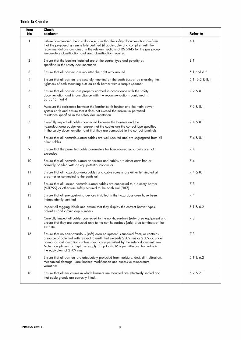
4.2 Safety checks Table 8 itemises all the important checks which should be carried out to ensure the safety of a barrier installation. Diligent use of the checklist will avoid the possibility of any important safety consideration being overlooked when installing, commissioning, modifying or servicing an installation that uses MTL700/700P range of barriers.
We recommend that on completion of any work on a barrier installation, each item on the checklist is again checked out, preferably by someone other than the person who actually carried out the work.
Each item on the checklist is cross-referred to the relevant section of the manual to which reference can be made for more detailed information.
5 MOUNTING THE BARRIERS (ENCLOSED SYSTEMS)
Although the construction of MTL700/700P range of barriers gives them IP20 protection, a higher IP rating and additional protection against mechanical damage and unauthorised modification can be provided by the ‘MT’ range of enclosures, which can mount up to 2, 5, 12, 24 or 32 MTL700/700P range of barriers in the non-hazardous (safe) area.

INM700 Rev 12 7
107 157 172 382
148
198 010
25
60 125
25*
100 175
Knockout hole, 05 407
200 (MT12)
17 06.5
Fixing lugs for MT12 The screw-on fixing lugs can be positioned as shown (left). *Add 5mm to depth if fixing lugsare used.
Figure 6: Enclosure dimensions (mm)
Figure 7: Method of mounting a typical enclosure
A type ’n’ approved steel enclosure is available in the range for protecting up to 20 barriers in Zone 2 areas. The dimensions and specifications of the enclosures are given in table 7 and figure 6 respectively.
5.1 Fitting the barriers into the enclosure Each enclosure is supplied ready-fitted with all the necessary accessories to allow immediate installation of barriers. To fit the barriers, remove the enclosure’s lid by releasing the captive screws (the MT20N enclosure’s lid is removed by also lifting it off its two hinges). Temporarily unclip the TGS7 tagging strip (not fitted on model MT2), then simply bolt each barrier via its two earth studs to the section of busbar provided, tightening all nuts to a torque of 2.3Nm using the ‘TQS7’ torque spanner or other suitable wrench. Note that these ‘Nyloc’ nuts will lose their anti-vibration feature after being tightened/released several times, so if possible avoid undoing them once they have been tightened.
Ensure that the barriers are mounted such that their hazardous-area terminals are adjacent to the row of terminals mounted alongside the busbar, or in the case of the MT5, the three small terminals mounted on the end brackets.
5.2 Mounting the enclosure Depending on the model utilised, there are up to three different methods of mounting enclosures, and these are illustrated in figure 7 and described later. The enclosure specifications section 3.6 details mounting methods, dimensions and kit provided for each model.
Care should be taken when mounting enclosures to ensure the internal temperature does not exceed the maximum permitted ambient temperature for the barriers (i.e. 60°C). For this reason enclosures should not be mounted in areas where they will be subject to direct sunlight or other sources of heat.
5.2.1 Corner screws/plugged knockout holes (not MT20N)
With this method, enclosures are mounted from the front using screws or bolts (not provided). First, using a small screwdriver, pierce the corner knockouts from the rear of the enclosures (not applicable on MT2 and MT5; holes are already provided). Then, from the front of the enclosures, insert suitable screws or bolts through the 5mm diameter apertures made by the removal of the knockouts, and fix the enclosures into position. The mounting dimensions are shown in figure 6. Finally, on MT12, MT24 and MT32 only, insert the plastic sealing plugs (provided) into the holes above the screws, and push them firmly into place to seal the knockout apertures, so as to preserve the enclosure’s IP65 integrity.
150
310
175
24
75
98
57
12
5*
198
157
15
0*
272
475
170
IINM700 rev11 8
Table 8: Checklist
Item No
Check section:– Refer to
1 Before commencing the installation ensure that the safety documentation confirms 4.1that the proposed system is fully certified (if applicable) and complies with the recommendations contained in the relevant sections of BS 5345 for the gas group, temperature classification and area classification required
2 Ensure that the barriers installed are of the correct type and polarity as 8.1specified in the safety documentation
3 Ensure that all barriers are mounted the right way around 5.1 and 6.2
4 Ensure that all barriers are securely mounted on the earth busbar by checking the 5.1, 6.2 & 8.1tightness of both mounting nuts on each barrier with a torque spanner
5 Ensure that all barriers are properly earthed in accordance with the safety 7.2 & 8.1documentation and in compliance with the recommendations contained in BS 5345: Part 4
6 Measure the resistance between the barrier earth busbar and the main power 7.2 & 8.1system earth and ensure that it does not exceed the maximum permitted resistance specified in the safety documentation
7 Carefully inspect all cables connected between the barriers and the 7.4 & 8.1hazardous-area equipment; ensure that the cables are the correct type specified in the safety documentation and that they are connected to the correct terminals
8 Ensure that all hazardous-area cables are well secured and are segregated from all 7.4 & 8.1other cables
9 Ensure that the permitted cable parameters for hazardous-area circuits are not 7.4exceeded
10 Ensure that all hazardous-area apparatus and cables are either earth-free or 7.4correctly bonded with an equipotential conductor
11 Ensure that all hazardous-area cables and cable screens are either terminated at 7.4 & 8.1a barrier or connected to the earth rail
12 Ensure that all unused hazardous-area cables are connected to a dummy barrier 7.3(MTL799) or otherwise safely secured to the earth rail (ERL7)
13 Ensure that all energy-storing devices installed in the hazardous area have been 7.4independently certified
14 Inspect all tagging labels and ensure that they display the correct barrier types, 5.1 & 6.2polarities and circuit loop numbers
15 Carefully inspect all cables connected to the non-hazardous (safe) area equipment and 7.3ensure that they are connected only to the non-hazardous (safe) area terminals of the barriers.
16 Ensure that no non-hazardous (safe) area equipment is supplied from, or contains, 7.3a source of potential with respect to earth that exceeds 250V rms or 250V dc under normal or fault conditions unless specifically permitted by the safety documentation. Note: one phase of a 3-phase supply of up to 440V is permitted as that value is the equivalent of 250V rms.
17 Ensure that all barriers are adequately protected from moisture, dust, dirt, vibration, 5.1 & 6.2mechanical damage, unauthorised modification and excessive temperature variations.
18 Ensure that all enclosures in which barriers are mounted are effectively sealed and 5.2 & 7.1that cable glands are correctly fitted.

INM700 Rev 12 9
M4
126
70 M4 x 20 fixing screw
85 21.1
Figure 9: Insulating mounting block IMB7
M4
97
70 M4 x 20 fixing screw
85 14.1
Figure 10: Insulating mounting block SMB7
14.5 04.4 3
25
Figure 8: Earth busbar EBB7
Figure 13: Earth terminal ETM7
5.2.2 Rear-fixing (not MT2, MT5 and MT20N) Enclosures are mounted from the rear with this method, using the M6 screws provided. First drill holes through the surface onto which the enclosure is to be mounted, positioned so as to align with the tapped holes at the rear of the enclosure. These positions are the same as for corner screws in paragraph 5.2.1 and are shown in figure 6. Then, using the M6 x 12 screws provided, fix the enclosure into place from the rear. It will be necessary to use longer M6 screws than those provided if the thickness of the material on which the enclosure is mounted exceeds about 6mm.
5.2.3 Fixing lugs All models can be mounted on a flat surface using the fixing lugs provided.
On models MT2 and MT5 the two plastic lugs can be positioned on either pair of opposite sides, as shown in figure 6. They are attached to the rear of the enclosure by the self-tapping screws provided.
On models MT12 and MT24, the plastic lugs are positioned one in each corner, and each can be attached in any one of three positions (see figures 6 and 7). The lugs are attached to the rear of the enclosure using the screws provided. Model MT32 is similar but uses six lugs: one in each corner, and two midway along the enclosure’s length. This extra lug on each side should be fixed at right-angles to the enclosure’s side, in either one of the two mounting holes.
Model MT20N has fixed mounting lugs, whose centres are shown in figure 6.
6 MOUNTING THE BARRIERS (UNENCLOSED SYSTEMS)
To simplify installation in circumstances where enclosures are not required, the parts needed are available either separately or as complete mounting kits for specified numbers of MTL700/700P barriers.
The range of accessories available for mounting MTL700/700P range of barriers as unenclosed systems is detailed in section 6.1. Our certified customer drawings (CD701 Series) containing full specifications of each item are also available. Section 6.2 details the simple step-by-step procedure for constructing a comprehensive barrier mounting, earthing and tagging installation using the separate part accessories and section 6.4 gives the assembly instructions for the mounting kits.
6.1 The MTL700 and 700P range accessories range
6.1.1 Earth busbar EBB7 Used for mounting and earthing MTL700/700P range of barriers. Available in 1-metre lengths, in nickel-plated brass.
6.1.2 Insulating mounting block IMB7 Used for mounting EBB7 earth busbars and insulating them from panel/structural earth to prevent invasion by fault currents. IMB7s are sufficiently high to provide tagging and earthing facilities for MTL3000 and 2000 Series interface units if required. They can be mounted on a flat surface, top-hat rail (to EN50 022 – 35 x 7.5; BS 5584; 35 x 27 x 7.3 DIN46277), or G-profile rail (to EN50 035 – G32; BS 5825; 32 DIN46277).
6.1.3 Insulating mounting block SMB7 An alternative to the IMB7, to reduce the overall height of the installation to 97mm. Mounts on a flat surface only.
6.1.4 Earth rail mounting bracket ERB7 For supporting and electrically connecting the earth rail to the busbar, it mounts over either type of mounting block. Made of 3 x 10mm tin- plated brass, the ERB7 is supplied with one bolt-down fitting for the rail – enabling easy removal for adding extra ETM7 terminals – and one16mm2 terminal for making an earth connection.
6.1.5 Earth rail ERL7 This rail mounts the earth terminals that are used to earth incoming cables and screens and attaches to the mounting blocks via an ERB7 earth rail mounting bracket. It is available in 1-metre lengths and is made of 3 x 10mm nickel-plated brass.
6.1.6 Earth terminal ETM7 Suitable for mounting on ERL7 earth rail to earth incoming cables and screens, with up to 2.5 terminals per barrier width possible. Supplied
3
10
Figure 12: Earth rail ERL7
58 72 10
11.5 25
3
Figure 11: Earth rail mounting bracket ERB7
11.
5

INM700 Rev 12 10
95
14.5 4.2
Figure 18: Surface mounting clips SMC7
in bags of 50.
6.1.7 Tagging strip TAG7 Provides tagging facilities for up to 64 barriers. Supplied in 1-metre
lengths, and complete with TGL7 label and six ‘clic’ rivets for securing purposes.
6.1.8 Tagging strip label TGL7 Additional labels for TAG7 tagging strip, available separately. Supplied in 0.5 metre lengths, in packs of 10.
6.1.9 Tagging strip seal TGS7
Secures TAG7 tagging strip and label to the installation, to prevent unauthorised removal and maintain barrier identification. Supplied in bags of ten.
6.1.10 ‘Take Care’ intrinsic safety labels Warning labels bearing the words ‘Intrinsically Safe System – TAKE
CARE’ are available for attaching to enclosures or in areas where intrinsically safe systems and equipment are in use. Plastic labels with adhesive fronts (ISL7) for attaching to the insides of transparent enclosure lids, and metal labels with adhesive backs (ISL3) are
available.
6.1.11 Torque spanner TQS7 For tightening barrier mounting studs. The spanner is set to a torque of 2.3Nm (20Ib in.) and fitted with a 7mm A/F socket.
6.1.12 Surface mounting clips SMC7 These clips are used for mounting small numbers of barriers on flat surfaces where it is not convenient or possible to use busbars. Supplied in bags of ten; two clips needed per barrier.
6.1.13 DIN-rail mounting kit DRK700 An MTL700/700P range of barrier fitted with the DRK700, can be attached to standard, ‘T’ section 35mm DIN rail, alongside MTL7000 and MTL7700 range of products. See Figure 19.
6.1.14 Dummy barrier MTL799 This accessory allows for expansion when designing a system and is a convenient means of reserving a position, or terminating spare leads and screens. It is packed as a standard MTL700/700P range of barrier, with hazardous-area terminals 3 & 4 internally connected to the fixing studs. Non-hazardous (safe) area terminals 1 & 2 are not connected. See figure 26 (page14).
6.1.15 Mounting kits Four mounting kits are available, the MK2 (2 barriers), MK5 (5 barriers), MK12 (12 barriers), and MK20 (20 barriers). Each kit provides facilities for mounting and earthing the barriers, connecting the IS earth cable, terminating earth screens and noting tagging information (except the MK2 kit). Assembly instructions are given in sections 6.4 and 6.5. See figures 22 and 23 (pages 12 and 13).
6.2 Constructing the installation Installing MTL700/700P range of barriers is very simple. The barriers mount on standard earth busbar which is supported by insulating mounting blocks, themselves mounting on any flat surface or suitable DIN rail. In addition, an earth rail plus terminals is provided for terminating cable screens, and a tagging strip allows the barrier and its location to be identified.
Figure 20 shows how the accessories fit together to make up the installation, and should be referred to while carrying out the construction procedure.
6.2.1 Determine the number of barriers to be mounted on the busbar. The maximum number is 25 between mountings, but a 1-metre length of busbar can accommodate up to 64 barriers. So for up to 25 barriers, cut a length of busbar with the required num- ber of mounting positions, plus two extra for the mountings. For 26 to 50 barriers, three extra mounting positions are required. For 51 to 64 barriers, four extra positions are required.
6.2.2 Position the busbar on the fixing studs of the IMB7 or SMB7 mounting blocks. The blocks should face the same way and be located not more than 25 spaces apart.
Figure 19: DIN-rail mounting kit DRK700
175
Figure 17: Torque spanner TQS7
140 (65*)
1ntrinsically Safe System
TAKE CARE 100 (40*)
Figure 16: ‘Take Care’ instrinsic safety label ISL3 or ISL7
25
Figure 15: Tagging strip seal TGS7
64
Figure 14: Tagging strip TAG7

INM700 Rev 12 11
Figure 21: Recommended clearances for mounted barriers (shaded portions show areas swept by barrier during installation and removal)
6.2.3 Fit the ERB7 earth rail mounting brackets also onto each mount- ing block’s studs, on top of the busbar, ensuring that the large terminals are on the hazardous-area side. Tighten the IMB7 or SMB7’s fixing nuts using the TQS7 torque spanner.
6.2.4 If SMB7 mounting blocks have been used, fix the whole assembly to a flat surface using the two screws located in each block. Installations using IMB7s can be similarly mounted, or alternatively on top-hat or G-profile rail. For rail mounting, check that the swing nuts are turned out of the way, and locate the IMB7s on the rail. As the appropriate screws are tightened, the swing nuts pivot into position under the edges of the rail, thus securing the assembly. (The two angled screws are for G- profile rail, and the two vertical screws for top-hat rail). It may be necessary to remove the surface mounting screws from the IMB7s to achieve a flush fitting onto the rail.
6.2.5 Mount the barriers on the busbar in the required positions, tightening all fixing studs using the TQS7 torque spanner, or a torque wrench set to 2.3Nm (20 Ib.in.). Note that damage to the threads may occur if a higher torque than this is applied. Ensure all the barriers’ hazardous-area terminals face the haz- ardous-area side. Where barriers are mounted in rows on par- allel busbars, the barriers in alternate rows should be reversed to keep the hazardous and non-hazardous (safe) area termi- nals apart. Also ensure that there is sufficient clearance to allow their removal and replacement, as shown in figure 21.
6.2.6 Slide the required number of ETM7 earth terminals onto the ERL7 earth rail, and fit this assembly into the large terminals on the ERB7 brackets. Tighten these large terminals using a 10mm A/F spanner.
6.2.7 Complete the installation by fitting the tagging facilities. First, take the 1-metre length of TAG7 tagging strip and remove the pack of four ‘clic’ rivets taped to the underside. Also, remove the clic rivets from both ends of the strip by pressing them out from the rear. The TGL7 tagging strip label can now be removed and, along with the TAG7 tagging strip, cut to length if necessary. After the TGL7 tagging strip label has been
marked with loop identification numbers etc., refit it into the TAG7 tagging strip and secure it by replacing one of the clic riv- ets. If the TAG7 has been cut to length, drill a 3.2mm diameter hole in the cut end, diagonally opposite the existing clic rivet (7.5mm along, 12.5mm in) to accommodate the tagging seal. Clip the TAG7 onto the installation, using the lugs located on the top of each mounting block. Finally, ‘seal’ the tagging information to the installation by fitting a TGS7 tagging strip seal through the hole drilled previously in the TAG7 tagging strip, and the vertical slot in the mounting block. The informa- tion on the TAG7 label and the barrier model numbers them- selves can both be seen at the same time, thus making it easy
Figure 20: Installation using the MTL700/700P
INM700 Rev 12 12
85
10
76
45
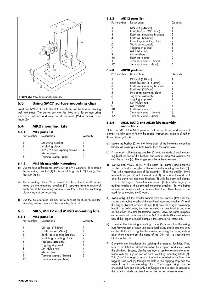
Figure 22: MK2 kit assembly diagram
6.5.2 MK12 parts list Part number Description Quantity
1 DIN rail (246mm) 1 2 Earth busbar (200.5mm) 1 3 Earth rail mounting brackets 2 4 Earth rail (215mm) 1 5 Insulating mounting block 2 6 Tag label assembly 1 7 Tagging strip seal 1 8 M4 Nyloc nuts 4 9 M4 washers 4 10 Earth rail clamp 2 11 Terminal clamps (16mm) 3 12 Terminal clamps (4mm) 6
6.3 Using SMC7 surface mounting clips Insert one SMC7 clip into the slot in each end of the barrier, pushing well into place. The barrier can then be fixed to a flat surface using screws or bolts up to 4.2mm outside diameter (M4 or similar). See figure 26.
6.4 MK2 mounting kits 6.4.1 MK2 parts list
Part number Description Quantity
1 Mounting bracket 1 2 Insulating block 1 3 3.9 x 9.5 self-tapping screws 4 4 M4 washers 4 5 Terminal clamp (4mm) 3
6.4.2 MK2 kit assembly instructions a) Use the four self-tapping screws (3) and M4 washers (4) to attach
the mounting bracket (1) to the insulating block (2) through the four M4 holes.
b) The insulating block (2) is provided to keep the IS earth (termi- nated on the mounting bracket (1)) separate from a structuralearth but, if the mounting surface is insulated, then the insulatingblock may not be necessary.
c) Use the 4mm terminal clamps (5) to connect the IS earth and ter- minating cable screens to the mounting bracket.
6.5 MK5, MK12 and MK20 mounting kits 6.5.1 MK5 parts list
Part number Description Quantity
1 DIN rail (156mm) 1 2 Earth busbar (99mm) 1 3 Earth rail mounting brackets 2 5 Insulating mounting block 2
6.5.3 MK20 parts list Part number Description Quantity
1 DIN rail (388mm) 1 2 Earth busbar (316.5mm) 1 3 Earth rail mounting brackets 2 4 Earth rail (330mm) 1 5 Insulating mounting block 2 6 Tag label assembly 1 7 Tagging strip seal 1 8 M4 Nyloc nuts 4 9 M4 washers 4 10 Earth rail clamp 2 11 Terminal clamps (16mm) 3 12 Terminal clamps (4mm) 10
6.5.4 MK5, MK12 and MK20 kits assembly instructions
Note: The MK5 kit is NOT provided with an earth rail and earth rail clamps, so take care to follow the special instructions given in d) rather than c) if using this kit.
a) Locate the busbar (2) on the fixing studs of the insulating mountingblocks (5), making sure both blocks face the same way.
b) Fit the earth rail mounting brackets (3) onto the studs of each mount- ing block on top of the busbar, and secure using M4 washers (9)and Nyloc nuts (8). The longer ends lie in the safe area.
c) (MK12 and MK20 only). Fit the earth rail clamps (10) onto theshorter protruding lengths of the earth rail mounting brackets (3).This is the hazardous side of the assembly. Slide the smaller (4mm)terminal clamps (12) onto the earth rail (4) and mount the earth railonto the earth rail mounting brackets (3) with the earth rail clamps(10). Fit the larger (16mm) terminal clamps (11) onto the longer pro- truding lengths of the earth rail mounting brackets (3), two beingmounted on one bracket and one on the other. These terminals areused for connecting the IS earth.
d) (MK5 only). Fit the smaller (4mm) terminal clamps (12) onto theshorter protruding lengths of the earth rail mounting brackets (3) andthe larger (16mm) terminal clamps (11) onto the longer protrudinglengths. In both cases, two are mounted on one bracket and oneon the other. The smaller terminal clamps serve the same purposeas the earth rail and clamps for the MK12 and MK20 while the func- tion of the larger terminal clamps is the same for all three kits.
e) To mount the insulating mounting blocks (5), check that the swingnuts forming part of each unit are turned away and locate the unitson the DIN rail (1). Tighten the screws accessing the swing nuts topivot them underneath the edge of the DIN rail, so securing theblocks to the rail.
f) Complete the installation by adding the tagging facilities. First,remove the label to add identification then replace and secure withthe clic rivet. Second, clip the tag label assembly (6) onto the instal- lation with the lugs on top of each insulating mounting block (5).Third,’seal’ the tagging information to the installation by fitting thetagging strip seal (7) through the hole in the tagging strip and thevertical slot in the mounting block. The tagging strip can beunclipped from one side only and hinged open to provide access tothe mounting studs and terminals of the barriers when required.
6 Tag label assembly 1 7 Tagging strip seal 1 8 M4 Nyloc nuts 4 9 M4 washers 4 11 Terminal clamps (16mm) 3 12 Terminal clamps (4mm) 3

INM700 Rev 12 13
7
6 Hazardous area side Non-hazardous (safe) area side
10
2
8 9
11
12 4
3
5
1
All dimensions in mm
Figure 23: MK5, MK12 and MK20 kit assembly diagram Note: MK5 has no items 4 and 10. See 6.5.4.d
7 WIRING INSTALLATION Before undertaking the installation of MTL700/700P range of barriers, section 4 of this manual should be read before commencing the instructions contained in this section. All instructions in this section apply to barriers mounted in our enclosures or as unenclosed systems. Figure 24 should be referred to for usage of earthing terminals in enclosures. For enclosures, all cables will need to be connected via suitable glands (not supplied), as described below.
7.1 Glanding cables into enclosures
7.2 Earthing the barriers To ensure correct and safe operation of the barrier system, it is vitally important that the installation is earthed properly. All MTL700/700P range of barriers should be connected to a high-integrity earth via a copper conductor. The resistance of this conductor should not exceed 1Ω, although in order to increase safety and minimise interference, a resistance of 0.1W should be aimed for whenever possible. The cross- sectional area of the conductor must be greater than 4mm2 (12AWG).
Where the barriers are mounted on a busbar, the conductor should be 7.1.1 MT2 and MT5 connected to the 16mm2
terminal on the ERB7 earth rail mounting
Two pre-drilled 20mm gland holes are provided in the base of each enclosure, fitted with push-in blanking plugs.
7.1.2 MT12 The enclosure has detachable top and bottom gland plates, for drilling by the user. This can be done with the gland plates in situ, or removed if preferred. To remove the gland plates, firmly press the plate retaining lip on the inside of the enclosure to release the front edge of the plate. Then, gently lever the plate retaining lip at the back of the enclosure to release the rear edge of the plate. Note that the embossed arrow on the inside of the gland plate always points towards the front of the enclosure when fitted, and then drill the gland holes in the required positions. The gland plates snap back into position.
7.1.3 MT20N This enclosure has detachable top and bottom gland plates, for drilling by the user. This can be done with the gland plates in situ, or removed if preferred. To remove the gland plates, simply unbolt them from the enclosure.
bracket. Alternatively, the connection can be made directly to the busbar using a vibration-proof ring tag. For greater integrity, a duplicate earth connection should be made to the terminal on a second ERB7 bracket.
On MT Series enclosures, the earth connections should be made to the ERB7 brackets as described above (or to the 4mm2 terminals in the case of the MT2), and fed into the enclosure via the non-hazardous (safe) area cable gland.
Although terminals 2 and 4 on 1-channel barriers are internally connected to the barrier earth studs, (MTL702, 705 and 706: terminal 4 only), they SHOULD NOT be used as a means of connecting the system to the high-integrity earth circuit.
To avoid the difficulty posed by the need to test the earth circuit periodically in accordance with the requirements of BS 5345, it is advisable to use two earth conductors for earthing the system, as shown in figure 25. It is then possible to connect a multimeter into the loop to measure the loop resistance without disturbing the circuit. In this case the resistance should not exceed 2Ω. This arrangement will also allow
DIN rail (item 1) Mounting centres hole diameters
MK5 140 4.5 nom.MK12 200 and 5.5 nom.
179 (choice) MK20 357 5.5 nom

Earthy terminals of 'dummy barrier' used to terminate screens
Spare cores terminated in dummy barier MTL799
Nuts omitted for clarity
Wires to be 4mm2
cross-sectional area (CSA) minimum
Figure 26: Use of the MTL799 dummy barrier (also shows alternative- mounting method using SMC7 clips
the circuit to be monitored continuously by a bonding integrity monitor such as the MTL2316, which gives warning if there is a significant increase in resistance, or if large currents are sensed. IS earth conductors should be identified by coloured insulating tape, preferably blue, wound around them at intervals along their length.
It is common practice (but not mandatory) to insulate IS earth busbars and associated conductors from the surrounding metalwork and plant earth cables. This minimises the possibility of the earth circuit being invaded by leakage or fault currents which, through common impedances, might interact adversely with this and other systems. It is far easier to design an insulated installation than to discover later that insulation is necessary, when disassembly and power removal will be unavoidable. MTL700/700P range of accessories IMB7 and SMB7 insulating mounting blocks are a convenient method of insulating busbars, as shown in figure
20. Further information about the earthing of IS systems is contained inBS 5345: Part 4: 1977, Section 3, Code 16.
If SCM7 surface mounting clips are used to mount a small number of barriers, the earth connections will have to be made directly to the barriers’ earth studs. Figure 26 shows a recommended method where the two earths are connected to different barriers, with the remaining studs all linked together. The earth conductors must have a minimum cross-sectional area of 4mm2. Hazardous-area cable screens can be connected to the earth studs, or terminal 3 and 4 of an MTL799 dummy barrier.
7.3 Connecting non-hazardous (safe) area cables to barriers
The non-hazardous (safe) area cables must be connected only to terminals 1 and 2 of MTL700/700P range of barriers. They should be segregated from hazardous-area cables and routed from the non-hazardous (safe) area equipment via the non-hazardous (safe) area loom, conduit or trunking. Care must be taken if standard barriers are to be connected to a non-hazardous (safe) area power supply. If the supply is connected the wrong way around, the barrier fuse will blow 14
and the unit will need replacing. (MTL702, 705, 706, 707, 707P and 708 overvolt-protected barriers cannot be damaged in this manner). For standard barriers, ensure also that the supply voltage does not exceed the working voltage (Vwkg) of the barriers as specified in section 3.2.
Do not connect barriers to non-hazardous (safe) area equipment that is supplied from, or contains, a source of potential with respect to earth that exceeds 250V rms or 250V dc under normal or fault conditions, unless specifically permitted to do so by the safety documentation. (Connection to non-hazardous (safe) area equipment fed from a three- phase 440V neutral earthed supply is permissible).
All unused non-hazardous (safe) area cables should be secured safely to terminals 1 and 2 of an MTL799 dummy barrier, or by some other suitable method.
7.4 Connecting hazardous-area cables to barriers
The hazardous-area cables must be connected only to terminals 3 and 4 of MTL700/700P range of barriers. They should be segregated from non-hazardous (safe) area cables and routed to the hazardous-area equipment via the hazardous-area loom, conduit or trunking.
Before making any connections, ensure that all energy-storing devices (i.e. devices that are not classified as ‘simple apparatus’) used in the hazardous area are certified compatible with the barrier combination being used. Then check that the cables used for connecting the barriers to the hazardous-area equipment conform with the type of cables
specified in the safety documentation. Make sure that the maximum permitted cable parameters stipulated for the particular types of barrier in tables 9 to 12 (BASEEFA) or tables 13 to 22 (FM) are not exceeded. In general, cable parameters are unlikely to present problems except where cables longer that 500m are used for Group IIC applications.
Hazardous-area equipment and its interconnections should be isolated from earth to the extent that it is capable of withstanding a 500V isolation test, but such tests can only be undertaken when the area is gas free. Fortunately however, most circuits may be tested at low voltages by first disconnecting at the barrier any cable connected directly to earth or returned via a barrier with a nominal voltage of less than 10V. The resistance to earth of the non-hazardous (safe) area terminals can then be checked with a multimeter and should be greater than 100kΩ.
Note: some hazardous-area instrumentation (e.g. pH and conductivity) is, by its nature, unable to withstand the 500V insulation test method mentioned above. Where this is the case, the system may alternatively comply with the installation requirements specified in IS sketch 121 (figure 27) and BS 5345, Part 4, 1977, Section 3, Code 16.
Hazardous-area earth returns and cable screens should be earthed via the ETM7 earth terminals mounted on the ERL7 earth rail (on the mounting bracket in the case of the MT2 enclosure). However, in the case of 1-channel barriers, earth returns and cable screens can be connected to terminal 4 of the barrier with which they are associated, because that terminal is internally connected to the earth studs.
All unused hazardous-area cables should be secured safely to terminals 3 and 4 of an MTL799 dummy barrier, or by some other suitable method.
Figure 26 shows the MTL799 used as a convenient technique for terminating screens and is another possible use.
INM700 Rev 12
Local distribution transformet
Resistance meter or bonding integrity monitor
Loop resistance < 2Q
Figure 25: Earthing with two conductors
4mm2 terminals for earthing hazardous area screens or earth
returns 16mm2 terminals for duplicated earth
connections
16mm2 terminal for safe area0V connections or power supply returns
Figure 24: Usage of earthing terminals

INM700 Rev 12 15
Where the hazardous area equipment is connected to earth either directly or indirectly, and/or it will not withstand a 500V insulation test to ground, (e.g. strain-gauge bridges with low-voltage insulation, pH and conductivity measuring electrodes, bare and/or earthed thermocouples, some level detecting elements), the following apply:
1. Safety requirements1.1 The pipe, vessel, or body of the hazardous-area apparatus and/or the adjacent metallic structure must be connected to the barri-
er busbar by a bonding conductor not less than 8mm2 cross-sectional area (CSA). With this size conductor the bonding conduc- tor must not exceed 200m in length. If the bonding conductor is less than 100m the conductor need only be 4mm2 in cross-sec- tional area.
1.2 Where bonding conductors are used, care should be taken to avoid invasion of other intrinsically-safe systems, which do not utilise bonding conductors, by elevation caused by any currents which may flow in the common earthing systems due to the presence of the bonding conductor. Where this possibility cannot be avoided, then the busbar on which the barriers are fitted should contain only barriers associated with bonded systems, and it should be earthed separately from other barrier busbars.
1.3 The hazardous-area equipment and/or adjacent metallic structure bond connections must be secure against vibration and corro- sion. A terminal of the type used on Type ‘e’ equipment is the required solution.
1.4 The barrier busbar connections must provide adequate termination facilities for the bonding conductor and usual ‘earth return’, by the provision of separate Type ‘e’ terminals.
1.5 Where the barriers are located in Zone 2, the enclosure and the wiring to the non-hazardous (safe) area connections of the bar- rier must comply with the requirements of Type ‘N’ protection.
2. Operational requirements2.1 This sketch shows the ‘0V’ rail of the non-hazardous (safe) area equipment returned to the barrier busbar by a separate insulated
conductor, and the structural earths of the barrier enclosure and safe-area equipment returned separately to the neutral star point. This technique reduces interference problems, but is not essential for safety.
2.2 In general, the use of barriers in all measurement leads reduces the possibility of earth circulating currents creating measurement problems.
3. Neutral star point earth3.1 Resistance to ‘terrestrial earth’ is determined by other regulations. It is NOT modified or determined by the intrinsic safety
Zone 0, 1 or 2 Zone 2 or safe area Non-hazardous (safe ) area
Hazardous area equipment incapable of withstanding insulation test
Enclosure
Barriers
Bonding conductor
Less than 100 metres: 4mm2 min. CSA
100 - 200 metres (max): 8mm2 min. CSA
Non- hazardous (safe) area equipment
0V
1n max.
Local distribution transformer
Figure 27: Bonding practice where hazardous area equipment cannot meet required standards of insulation from earth requirements.

INM700 Rev 12 16
7.5 Cable parameters for MTL700 range – BASEEFA(ATEX) & FM Table 9: Maximum cable parameters (gas group IIC) (for notes 1, 2, and 3, see bottom of page)
0.31*
System combination
BASEEFA system
Cert. No.
Earth 1
return used?
BASEEFA Maximum permissible cable parameters for group IIC (hydrogen)
Matched 2power
W (BASEEFA)Capacitance µF Inductance mH or L/R ratio µH/Ω
1x715P 4x764ac
Ex92C2425 Yes 0.135 0.23 39.3 0.91
2 x 761ac channels 2 x 764ac channels 2 x 766ac channels
Ex842125 Yes 0.2 0.24 11.6 1.01
4 x 761ac channels 2 x 764ac channels
Ex842125 Yes 0.2 0.2 12.7 0.98 4x761Pac channels 2x766Pac channels Ex92C2424 Yes 0.18 0.17 18.4 1.172 x 764ac channels 4 x 766ac channels
Ex842128 Yes 0.2 0.28 11 1.04 758 + 761ac Ex872392 Yes 0.42 0.013 10.5 3.27
BASEEFA Maximum permissible cable parameters for group IIB (not safe for group IIC)
4 x 764ac channels 4 x 766ac channels
Ex842128 Yes 0.6 1.1 32.6 1.12 2 x 768 channels Ex842114 Yes 0.78 1.8 70 1.62 2 x 768 channels Any number of 786 channels
Ex842114 Yes 0.39 1.8 46.6 1.62
2 x 779 channels Ex842114 Yes 0.39 4.3 83 1.3 2 x 779 channels Any number of 786 channels
Ex842114 Yes 0.39 4.3 55.6 1.3 * L/R = 31µH/ΩThe tables give the maximum permitted cable parameters (including cable and load) for hazardous-area circuits in group IIC and IIB gases. However, the tables are by no means exhaustive and for full details of other safe combinations, consult either BASEEFA system certificates Ex832469, Ex92C2374 or Ex92C2376 or MTL. The MTL702 is covered by BASEEFA system certificate Ex842308, and the MTL706 by Ex872513. In practice cable parameters rarely present a problem, as all cables normally used for instrument interconnection have L/R ratios below 25µH/Ω and capacitance below 200pF per metre. Note 1 If a ‘No’ value is not quoted for a barrier, use the ‘Yes’ value. Note 2 Note 3
The maximum power that can be drawn from the barrier combination under fault conditions. Used for assessing the temperature classification of ‘simple’ hazardous-area apparatus. Values for Groups IIA and IIB are given on certificates BAS01ATEX7202 and BAS01ATEX7203. For FM permitted combinations, refer to our document SCI-88 (via FM ref 1H8A1.AX).
Barrier model
number MTL
Number of single channels interconnected
within hazardous area
Earth 1
return used?
Maximum permissible cable parameters Matched 2
power W
(BASEEFA)
BASEEFA (ATEX) (group IIC) FM (groups A&B) Capacitance
µFInductance or L/R ratio
mH µH/Ω Capacitance
µFInductance
mH
702+ 1 Yes 0.110 2.39 47 0.17 2.2 0.782 706+ 1 Yes 0.083 3.05 56 0.12 4.0 0.65 707+ Both Yes 0.083 3.05 56 0.12 4.0 0.65 708+ 1 Yes 0.083 3.05 56 0.12 4.0 0.65 710 1 Yes 3.0 0.91 74 3.0 1.0 0.50 710P 1 Yes 3.0 0.38 44 4.89 0.22 0.75 715 1 Yes 0.580 1.45 66 0.7 1.4 0.56 715P 1 Yes 0.580 0.33 28 1.04 0.23 1.09 722 1 Yes 0.165 1.45 45 0.2 1.4 0.81 722P 1 Yes 0.165 0.30 32 0.33 0.53 1.18728 1 Yes 0.083 3.05 56 0.12 4.0 0.65 728P 1 Yes 0.083 1.82 44 0.16 2.86 0.83 751ac 1
2Yes Yes No
100 100 100
3.72 0.96 3.72
1464 558 732
1000 1000 1000
4.5 1.2 4.5
0.025 0.05 0.05
755ac 1 2
3 4
Yes Yes No No Yes No
100 100 40 40 40 40
0.46 0.13 0.41
0.125 0.035 0.06
145 69 73 48
31.25 42
1000 150 150
– – –
0.4 0.1 0.1 – – –
0.225 0.45 0.45 0.68 0.92 0.92
758 1 2
Yes Yes
11.1 11.1
0.070 0.02 26
106.0 6.0
0.05 0.02
1.40 2.80
760ac 1 2
Yes Yes
3.0 3.0
0.91 0.20
74 27
3.0 3.0
0.9 0.2
0.50 1.00
761ac 1 2
4
6
Yes Yes No Yes No Yes No
4.9 4.9
0.31 0.42 0.42 0.42 0.42
3.72 0.91 3.72 0.20 0.37
0.085 0.13
163 62 81
26.39 37.78 14.39 18.67
3.1 0.4 0.4 – – – –
3.5 1.0 1.0 – – – –
0.225 0.45 0.45 0.90 0.90 1.35 1.35
761Pac 2 Yes 0.31 56 306 0.43 14.4 0.115 764± 1
2Yes Yes
1.41 1.41
240 61 1000
360 1.5 1.0
200 60 0.036
0.072764ac 1
2Yes Yes No
1.41 1.41 0.125
240 61 240
1000 360 500
1.5 0.18 0.18
200 60 60
0.036 0.072 0.072
765ac 1 2
Yes Yes
0.58 0.58
1.45 0.32
66 22
0.7 0.7
1.3 1.4
0.56 1.125
766ac 1 2
Yes Yes No
1.41 1.41 0.125
5.8 1.47 5.8
151 58 75
1.5 0.18 0.18
5.6 1.5 1.5
0.24 0.48 0.48
766Pac 2 Yes 1.41 0.34 29 0.22 0.20 0.942 767 1
2Yes Yes
0.58 0.58
1.45 0.32
66 22
0.7 0.5
1.7 0.4
0.56 1.125
768 1 Yes 0.165 1.45 45 0.2 1.7 0.81 772ac 1
2Yes Yes
0.165 0.165
6.77 1.45
89 34
0.2 0.2
6.0 1.8
0.404 0.808
778ac 1 2
Yes Yes
0.083 0.083
16 3.05
107 42 0.12
0.1214 4.2
0.327 0.654
779 1 Yes 0.083 3.05 56 0.12 4.0 0.65 786 1 or 2 Yes 0.083 – – 0.11 500 –
787 & 787S Both Yes 0.083 3.05 56 0.11 4.0 0.65 787SP 2 Yes 0.083 1.82 44 0.13 2.70 0.835
788 & 788R Both Yes 0.083 0.33 25 0.11 0.5 0.92 791 Both No 0.165 0.30 32 0.24 1.18796 Both Yes 0.10 1.94 34 0.13 2.0 0.81
BASEEFA (group IIB) FM (group C) 707P 2 Yes 0.65 5.65 127 0.45 6.21 1.19 729P 1 Yes 0.65 5.65 127 0.49 6.25 1.19

INM700 Rev 12 17
Hazardous location equipment (see note 1 - after table 21))
Hazardous location Class i Div 1 Groups A,B,C,D
Non-hazardous location
Class ii Div 1 Groups E,G
Class iii 1 - channel barriers
Ground (1Q max) Note: one channel of an MTL779 may be used in place of an MTL728
* One channel of an MTL779 can be used in place of an MTL728 Figure 28: 1–channel barrier connections
Hazardous location equipment (see note 1 -on page 20)
Hazardous location Class i Div 1 Groups A,B,C,D Class ii Div 1 Groups E,G Class iii
Non-hazardous (safe) location
2 - channel barriers- no ground return
Ground (1n max) Note: No ground return permitted,nor grounded shields or conduit.
Figure 29: 2–channel barrier connection with no ground return
Hazardous location equipment (see note 1 -on page 20)
Hazardous location equipment (see note 1 -on page 20)
Hazardous location Class i Div 1 Groups A,B,C,D Class ii Div 1 Groups E,G Class iii
Non-hazardous (safe) location
Each channel with ground return
Ground (1n max) Note: Ground returns for each piece of hazardous location equipment must be run separately
Figure 30: 2–channel barrier connection with separate ground return for each channel
Hazardous location Non-hazardous (safe) location
Non-hazardous (safe) location devices V 250V max. (see note 2 - on page 20)
Hazardous location equipment (see note 1 -on page 20)
Hazardous location Class i Div 1 Groups A,B,C,D Class ii Div 1 Groups E,G Class iii
Non-hazardous (safe) location
2 - channel barriers optional ground return
2 - channel barrier
Optional
Optional
Ground (1n max)
Figure 31: 2–channel barrier connection with optional ground return
7.6 Entity concept parameters for MTL700 range – FM
Table 10: Entity concept parameters for 1-channel MTL700 barriers (figure 28)
Table 11: Entity concept parameters for 2-channel MTL700 barriers with no ground return (figure 29) and separate ground returns for each channel (figure 30)
Barrier model No. MTL
Figure 29 Figure 30
Voc (V)
Isc (mA)
Ca (µF)
La (mH)
Voc (V)
Isc (mA)
Ca (µF)
La (mH)
751 1.92 89 1000 4.5 0.96 89 1000 4.5755 5.92 296 1000 0.4 2.96 296 1000 0.4 758 – – – – 8.5 821 6.0 0.05 760 10.03 97 3 3.5 10.3 194 3.0 0.9 761 18.08 99 0.40 3.5 9.04 99 3.1 3.5 764± 13.25 6 1 800 12.05 12 1.5 200 764ac 24.10 12 0.18 200 12.05 12 1.5 200 765 15.08 75.4 0.70 6 15.08 147 0.7 1.3 766 24.10 80.4 0.18 5.6 12.05 80 1.5 5.6 767 16.35 75.8 0.50 6 15.15 147 0.7 1.7 768 23.33 73.5 0.20 6 22.13 147 0.2 1.7 772 22.13 36.9 0.20 22 22.13 73 0.2 6 778 28.23 23.6 0.12 58 28.23 46 0.12 14 779 29.37 46.5 0.11 14 28.17 93 0.12 4 786 29.20 0 0.11 500 28.00 0 0.12 500 787 (28V ch) 29.74* 94* 0.10* 4* 28.54 94 0.11 4 787 (diode ch) – – – – 28.00 0 0.12 500 788, 788R (28V ch) 28.75* 82* 0.11* 5.6* 28.15 93 0.12 4 788, 788R (10V ch) – – – – 10.04 189 3.0 1 796 (26V ch) 27.30* 40* 0.13* 22* 26.10 86 0.14 4.7 796 (20V ch) – – – – 20.05 51.4 0.3 13
* Parameters when barrier channels are interconnected
Table 12: Entity concept parameters for 2-channel MTL700 barriers with optional ground return (figure 31)
Barrier model no.
(MTL)
Voc
(V)
Isc
(mA)
Ca
(µF)
La
(mH)
707 28.1 93 0.12 4.0758 8.1 1482 6.0 0.02 787S 28.7 93 0.11 4.0
Non-hazardous (safe) location devices V 250V max. (see note 2 - on page 20)
2 1
2 - channel barrier
Non-hazardous (safe) location devices V 250V max. (see note 2 - on page 20)
2 1
2 - channel barrier
Non-hazardous location devices V - 250V max. (see note 2 - after table 21)
2
1 - channel barrier
Barrier model no.
(MTL)
Voc
(V)
Isc
(mA)
Ca
(µF)
La
(mH)
702 25.11 125 0.17 2.2705 28.1 93 0.12 4.0 706 28.1 93 0.12 4.0 708 28.1 93 0.12 4.0 710 10.03 189 3.0 1.0 715 15.06 146 0.7 1.4 722 22.08 146 0.2 1.4 728* 28.12 93 0.12 4.0
3 4
3 4 3 4
3 4 2 1

INM700 Rev 12 18
Hazardous location equipment (see note 1 -on page 20)
Hazardous location Class i Div 1 Groups A,B,C,D Class ii Div 1 Groups E,G Class iii
Non-hazardous (safe) location
Strain gauge
Ground (1n max)
Figure 32: Strain gauge bridge combination using MTL761/764 barriers
Hazardous location equipment (see note 1 -on page 20)
Hazardous location Class i Div 1 Groups A,B,C,D Class ii Div 1 Groups E,G Class iii
Non-hazardous (safe) location
Strain gauge bridge combination
Ground (1n max)
Figure 33: Strain gauge bridge combination using MTL761/764/766 barriers
Fieldbus Terminator FBT1
Hazardous location equipment (see note 11 - on page 20)
Hazardous location equipment (see note 11 - on page 20)
Hazardous location Class i Div 2 Groups A,B,C and D Class ii Div 2 Groups F and G Class iii, Div 2
Non-hazardous (safe) location
MTL791
Vt = 22V It = 233mA Po = 1.18W
Ground (1n max)
Figure 34: Fieldbus barrier system using MTL791 barrier and FBT1 terminator
Table 13: Entity concept parameters for strain gauge bridge systems using MTL761/764 barriers (figure 32)
Table 14: Entity concept parameters for strain gauge bridge systems using MTL761/764/766 barriers (figure 33)
Table 15: Entity parameters for Fieldbus barrier MTL791 and terminator FTB1 (figure 34)
7.8 Entity concept parameters for MTL700P range – FM
Table 16: Entity concept parameters for single channel MTL700P barriers with ground return (see figure 28 and notes 6 to 9)
Barrier model No.
MTL
Groups Voc (V)
Isc (mA)
Ca (µF)
La (mH)
710P+/- A, B 9.0 267 4.89 0.22710P+/- C, E 9.0 267 14.6 2.23 710P+/- D, F, G 9.0 267 39.1 4.22 715P+ A, B 13.7 264 1.04 0.23715P+ C, E 13.7 264 3.13 2.27 715P+ D, F, G 13.7 264 8.37 4.30 722P+ A, B 20.1 194 0.33 0.53722P+ C, E 20.1 194 0.99 4.33 722P+ D, F, G 20.1 194 2.65 7.96 728P+ A, B 26.3 112 0.16 2.86728+ C, E 26.3 112 0.49 12.0 728P+ D, F, G 26.3 112 1.32 23.8 729P+ C, E 26.3 160 0.49 6.25729P+ D, F, G 26.3 160 1.32 11.6
Non-hazardous (safe) location devices V 250V max. (see note 10 - on page 20)
2 1
Group Ca (µF)
La (mH)
L/R µH/Ω
A, B 0.24 0.31 31C, E 0.74 2.97 121
D, F, G 1.99 5.50 242
Non-hazardous (safe) location devices V 250V max. (see note 2 - on page 20)
2 1
MTL761 ac
2 1
MTL764 ac
2 1
MTL766 ac
Group Ca (µF)
La (mH)
A & B 0.2 0.2C 0.6 0.6 D 1.6 1.6
bridge combination Non-hazardous (safe) location devices V 250V max. (see note 2 - on page 20)
2 1
MTL761 ac
2 1
MTL764 ac
2 1
MTL761 ac
Group Ca (µF)
La (mH)
A & B 0.2 0.24
3 4 3 4
3 4 3 4 3 4
3 4 3 4

INM700 Rev 12 19
Table 17: Entity concept parameters for 2-channel MTL787SP barriers with diode return (figures 29, 30 and 31 and notes 6 to 9)
Figure 29 Figure 30 Figure 31 Model No. (MTL)
Groups Voc (V)
Isc (mA)
Ca (µF)
La (mH)
Voc (V)
Isc (mA)
Ca (µF)
La (mH)
Voc (V)
Isc (mA)
Ca (µF)
La (mH)
787SP A, B 28.9 115 0.13 2.70 25.9 110 0.17 2.93 28.9 115 0.13 2.70(28V ch) C, E 28.9 115 0.39 11.52 25.9 110 0.51 12.3 28.9 115 0.39 11.52
D, F, G 28.9 115 1.06 22.57 25.9 110 1.38 24.3 28.9 115 1.06 22.57 787SP A, B – – – – 25.9 0 0.17 1000 – – – –
(diode ch) C, E – – – – 25.9 0 0.51 1000 – – – – D, F, G – – – – 25.9 0 1.38 1000 – – – –
Table 18: Entity concept parameters for two-channel MTL700P barriers with an optional ground return (figure 31 and notes 6 to 9)
Table 19: Entity concept parameters for two-channel MTL700P barriers with sep- arate ground returns (figure 30 and notes 6 to 9)
Barrier model No.
MTL
Groups Voc (V)
Isc (mA)
Ca (µF)
La (mH)
707P+ C, E 27.4 160 0.45 6.21 707P+ D, F, G 27.4 160 1.20 11.5 761Pac A, B 18.0 50 0.43 14.4761Pac C, E 18.0 50 1.29 53.0 761Pac D, F, G 18.0 50 3.46 119.0 766Pac A, B 23.0 297 0.22 0.20766Pac C, E 23.0 297 0.66 1.72 766Pac D, F, G 23.0 297 1.77 3.39
Note 1: The hazardous-location-mounted equipment may be switches or ther- mocouples. Other apparatus such as RTDs, LEDs, non-inductive resistors, (and strain-gauge load cells for the systems shown in fig- ures 32 and 33), may be used if the auto-ignition temperature of the hazardous location is greater than T4 (275°F, 135°C). For the sys- tems shown in figures 28, 29 and 30, certified devices with the cor- rect entity concept parameters can also be used.
Note 2: The non-hazardous location or control-room mounted equipment should not use nor generate more than 250V rms.
Note 3: For guidance on the installation see ANSI/SA RP 12.6. Note 4: Five MTL700 range of barriers are approved for installation in Group F: MTL705, 707, 708, 787S and 758. All MTL700P range of barriers
are approved for Group F. Note 5: Full details of all approved combinations are available on MTL
drawing No. SCI-88 Notes 6 to 9 inclusive relate to tables 16 to 19 inclusive Note 6: The barriers are associated apparatus and, when mounted in an
appropriate enclosure can be installed in the following areas: a) Non-hazardous locationsb) Class 1, Division 2, Groups A, B, C, and D hazardous locationsc) Class II, Division 2, Groups F and G hazardous locationsd) Class III, Division 2 hazardous locations
Note 7: Barriers must be installed in enclosures meeting the requirements of ANSI/ISA–S82
Note 8: Use Factory Mutual Research Corporation approved dust-tight enclosures appropriate for environmental protection for the following locations:– a) Class II, Division 2, Groups F and G hazardous locationsb) Class III, Division 2 hazardous locations
Note 9: For installation guidance see ANSI/ISA 12.6 and the National Electrical Code. See also Installation drawing SCI–326
Notes 10 to 14 inclusive relate to table 15 Note 10: The non-hazardous (safe) location equipment must not generate or
use voltages in excess of 250V rms. or dc Note 11: The hazardous location equipment. Any number of FMRC approved
devices which meet the power and entity parameter requirements below may be connected to the Fieldbus:- a) All device's electronic circuitry which interface directly to thefieldbus must be powered from fieldbus power. Other power sources in the devices (if any) must be galvanically isolated from the fieldbus power. b) Vmax of all devices must be equal to or greater than 22V.c) Imax of all devices must be equal to or greater than 233mA.d) Pmax of all devices must be equal to or greater than 1.18W. e) The sum of all devices unprotected input capacitance Ci, plusthe cable capacitance must be equal to or less than Ca for the appli- cable Gas Group in Table 15. f) The sum of all devices unprotected input inductance Li, plus thecable inductance must be equal to or less than La for the applicable Gas Group in Table 15.
Note 12: For guidance on installation see ANSI/ISA RP12.6 and the USA National Electric Code.
Note 13: The barrier must be installed in enclosures meeting the requirements of ANSI/ISA – S82 and the USA National Electric Code.
Note 14: Use FMRC – approved, or NRTL – listed, dust – ignition proof enclo- sures appropriate for environmental protection in Class II, Division 2, Groups F and G, and Class III Hazardous Locations.
7.9 Final check After completing the installation, each item contained in the checklist (table 8) should again be checked out by a competent person, preferably someone who has not been involved in the work.
8 MAINTENANCE Since the MTL700/700P range of barriers are encapsulated they cannot be repaired, but provided they are connected correctly to the circuits they are intended to protect, and provided those circuits are not themselves defective, barrier defects are unlikely to occur. For these reasons, servicing of barrier installations consists principally of the routine inspection and earth testing described in this section.
If replacements do have to be fitted however it is worth checking, in the case of barriers connected directly to power supplies, if one of the new overvolt-protected models can be substituted. These models can tolerate supply voltages up to 35V dc without blowing their fuses, and can therefore eliminate the problem of poorly regulated supplies. Further information about the maintenance of barrier installations is given in BS 5345: Part 4: 1977, Section 4.
8.1 Routine inspection At intervals of not more than two years (more frequently for particular environments), visually check the barrier installation to check the following points.
When undertaking these checks, personnel should comply with all the regulations relating to the safety of the plant and personnel. Great care must be taken to prevent any direct interconnection between hazardous and non-hazardous (safe) area circuits. The instructions given in section 4 of this manual should be observed at all times.
Barrier model No. MTL
Groups Voc (V)
Isc (mA)
Each channel Ca (µF)
Each channel La (mH)
707P+ (return) C, E 14.1 0 2.85 1000707P+ (return) D, F, G 14.1 0 7.62 1000 707P+ (signal) C, E 26.4 160 0.49 6.21 707P+ (signal) D, F, G 26.4 160 1.31 11.5 761Pac A, B 9.0 25 4.89 54.8 761Pac C, E 9.0 25 14.6 194.0 761Pac D, F, G 9.0 25 39.1 475.0 766Pac A, B 11.5 149 1.87 1.25766Pac C, E 11.5 149 5.63 7.16 766Pac D, F, G 11.5 149 15.0 13.4

INM700 Rev 12 20
8.1.1 Barriers should be of the types and polarities specified in the safety documentation.
8.1.2 The barriers should be attached securely to the earth busbar, thus making a good connection to the IS earth. Use a TQS7 torque spanner or other suitable wrench to check that each barrier's two ‘Nyloc’ nuts are tightened to a torque of 2.3Nm (20 lb.in.).
8.1.3 There should be no signs of damage or corrosion to the bar- riers or the IS earthing system.
8.1.4 All connections should be properly made, and the tightness of the hazardous and non-hazardous (safe) area terminals on the barriers checked.
8.1.5 Interconnecting cables should be of the type and rating spec- ified in the safety documentation, and not frayed or other- wise damaged.
8.1.6 All earth returns and cable screens from the hazardous area should be connected to earth via an earth rail and terminals.
8.1.7 Visually examine the earth conductors and ensure that they are not damaged in any way, and that their terminations are secure and free from corrosion.
8.1.8 Using a low voltage, low-current test meter (i.e. a meter whose output does not exceed 3V and 50mA), measure the resistance between the earth busbar and the neutral star point of the supply and ensure that it does not exceed 1W. Record the reading. A consistent reading repeated over a long period of time is indicative that the earth return is sound and likely to remain so. If two earth conductors are used as described in section 7.2, the loop resistance should be meas- ured as described in that section. The reading obtained should not exceed 2Ω.
Important note: do not attempt to perform a high-current earth resistance test unless it is confirmed by the authority in charge of the plant that the plant is gas free.
9 FAULT-FINDING Most barrier-protected systems are relatively simple and can be checked easily for operation. However, fault-finding procedures can be undertaken only after notifying all personnel concerned with plant safety and ascertaining that it is safe to proceed.
While it is not possible to describe fault-finding procedures for every type of barrier-protected circuit, there are several guidelines that can help to speed up the process.
The fault-finding procedures described in this section assume the use of a modern digital multimeter as this is the meter most commonly used. However, other test meters can be used provided that their characteristics when measuring silicon diodes are known.
If a diode chain is involved when testing a barrier, it is useful to remember that many modern digital multimeters cater for such circuits by the provision of a diode test function. These meters usually pass 1mA through the diode and measure the voltage across it. When measuring more than two diode drops in series it is worth noting that the full scale range of some multimeters is only 2V on the diode test range. Therefore with three or more diode drops it is possible that the meter may indicate over-range and any voltage drop of more than 4V has been indicated in the test tables (this section and section 11) as infinity.
Zener diodes and ordinary silicon diodes have a typical forward voltage drop of approximately 0.6V per diode. Diode return paths with schottky diodes have a typical voltage drop of <0.3V for each diode in the chain, e.g. MTL787S and 787SP.
Figure 35 shows a typical switch-status transfer circuit protected by an MTL787S+ barrier, which can be used to illustrate some of the fault- finding techniques discussed in this section. To determine the serviceability of barriers, proceed as described in the remainder of this section, but whenever possible always check barriers by working on the non-hazardous (safe) area terminals and the circuits connected directly to them.
9.1 Power supply check Check that the power supply is available to the barrier circuit and that the voltage across the supply and with respect to earth is correct. For example, referring to figure 35, the presence of 24V on terminal 1 and 12V on terminal 2 when the hazardous-area switch is closed confirms the serviceability of almost the complete circuit.
9.2 Barrier resistance test (not MTL702, 705, 706, 707, 707P and 708)
If testing a barrier in situ, refer to figure 35 and proceed as follows:
9.2.1 Disconnect the hazardous-area cables from the barrier, termi- nals 3 and 4, and connect the cables to earth via the earth rail or some other means, or alternatively insulate them completely.
9.2.2 Disconnect the non-hazardous (safe) area cables, terminals 1 and 2, and insulate them completely to prevent them from shorting together, to other cables or earth. Be careful when handling non-hazardous (safe) area cables; the relay contacts in figure 35 for example could be carrying mains voltage.
9.2.3 Measure the end-to-end resistance of the barrier by connect- ing a digital multimeter (set to a suitable ohms range) between terminal 1 and 3. The reading should be slightly less than the maximum end-to-end resistance quoted in sec- tion 3.2, or approximately 10 to 20% higher than the figure specified in the safety description. For the MTL787S+ the reading should be in the range 317 to 340Ω.
9.2.4 Check the serviceability of the diode-return channel by select- ing the diode test function on the test meter and connect between terminal 4 (+ve) and 2 (–ve). This will measure the forward voltage drop of the MTL787S’s three Schottky diodes in the chain, and a reading of less than 0.9V should be expected. Then connect between terminal 2 (+ve) and 4 (–ve) for a reading of × for the reverse voltage drop.
9.2.5 Tests 9.2.3 and 9.2.4 confirm the continuity of both channels of the barrier. If either channel is open-circuit it is most like- ly that the fuse has blown, in which case the non-hazardous (safe) area circuit should be investigated. If this is not the case and the fault has not been found, then carry out the tests in sections 9.3 and 9.4, and if a fault is still not found, remove the barrier for bench testing as follows:
9.2.6 Remove the suspect barrier from the equipment and take it to a suitable area where it can be tested in accordance with section 11 Barrier tests. If the barrier is found to be defec- tive, fit a new one of the appropriate model number.
Caution: After the removal of the barrier, ensure the safe-area and hazardous-area cables disconnected under 9.2.1 and 9.2.2 are either connected to an MTL799 dummy barrier or insulated completely.
9.3 Earth faults Most intrinsically safe circuits are isolated from earth in the hazardous area. If it is suspected that a system earth fault exists, proceed as follows:
Hazardous area
Non-hazardous (safe) area
340n
3 1 24V +
4 2 12V
30mA
400n 12V relay
0V
High-integrity earth
Figure 35: Switch status transfer circuit using MTL787+

INM700 Rev 12 21
Hazardous area Non-hazardous (safe) area
Compensating cable
MTL755 Non-hazardous (safe) area equipment
Callibration equipment
High integrity earth
Figure 36: Calibrating a thermocouple barrier circuit
Hazardous area Non-hazardous (safe) area
MTL755 Non-hazardous (safe) area equipment
Bridge supply
Measurement Measurement x x
y y
Variable resistance
Variable resistance
High integrity earth
Figure 37: Calibrating an RTD barrier circuit
9.3.1 Disconnect the hazardous and non-hazardous (safe) area cables from the barrier terminals and either temporarily insu- late them, or secure them safely to the appropriate terminals of an MTL799 dummy barrier.
9.3.2 For the barrier shown in figure 35 the readings shown in table 20 should be obtained when connecting a test meter with the diode test function selected.
9.3.3 In the case of the circuit shown in figure 35, with the haz- ardous-area cables connected to the terminals, and the test meter connected between terminals 1 (+ve) and 2 (–ve) a read- ing of × will be obtained if the switch is open and a reading of approximately 1.2V if the switch is closed, and no earth faults are present. To check if either of the hazardous-area cables is shorted to earth, connect the test meter as in table 21 which shows the readings that will indicate a fault to earth.
Table 20: Barrier earth fault tests with hazardous and non-hazardous (safe) area cables disconnected
Positive lead on terminal:
Negative lead on terminal:
Test meter reading:
1 Earth studs ∞ Earth studs 1 1.2V
2 Earth studs ∞ Earth studs 2 1.2V
1 2 ∞ 2 1 ∞
Table 21: Barrier earth fault tests with hazardous and non-hazardous (safe) area cables connected
Positive lead on terminal:
Negative lead on terminal:
Test meter reading:
Cable fault from terminal:
1 Earth studs
Earth studs 2
0V 0.9V
3 to earth 4 to earth
9.4 Faults between barrier channels If it is suspected that faults exist between the channels of a 2-channel barrier, proceed as follows: (Note that these tests are not applicable to MTL751 or 755 barriers). 9.4.1 Disconnect the hazardous and non-hazardous (safe) area
cables from the barrier terminals and either temporarily insu- late them, or secure them safely to the appropriate terminals of an MTL799 dummy barrier.
9.4.2 With a digital multimeter (set to diode test), check that there is an open circuit between the two channels of the barrier (terminal 1 to terminal 2), and in at least one direction between the earth studs and terminal 1, and the earth studs and terminal 2.
10 THERMOCOUPLE AND RTD TESTS 10.1 Thermocouple circuit testing
Thermocouple test and calibration equipment is not usually certified intrinsically safe and therefore requires special authorisation before it can be used for testing or calibrating thermocouple circuits in hazardous areas. To overcome this problem the thermocouple circuits can be protected by using an MTL760 barrier as shown in figure 36. The barrier allows the thermocouple output to be measured without the need to get special authorisation to use the thermocouple test equipment.
As it is seldom possible to accurately measure the temperatures of thermocouples located in hazardous areas, a safe means is required of adjusting the calibration tables to compensate for the plant temperature. This can be achieved by disconnecting the compensating cables from the thermocouple, shorting them together, and then measuring the temperature of the shorting point.
10.2 Resistance thermometer detector circuit testing
Resistance thermometer detector (RTD) circuits can be tested by disconnecting the measuring leads from the RTD head in the hazardous area and connecting them to a resistance box. Sometimes it is more convenient to connect the resistance box in the non-hazardous (safe) area, for instance at point xx as shown in figure 37. However, in this case the RTD must be shorted out, or allowance must be made for its temperature. The effect of a negative temperature change can be simulated by connecting the resistance box in the measurement lead at point yy. The advantage of connecting the resistance box at the RTD head is that any leakage can also be determined by connecting the resistance box at point yy.
11 BARRIER TESTS Note: There is no requirement for barriers to be subjected to routine testing if they are in normal use.
The tests given in this section have been included to enable users to carry out additional tests to those given in section 8 if they suspect the performance of the barriers. Barriers which pass these tests satisfactorily are not likely to incur an unacceptable level of risk or cause a circuit malfunction.
From tables 26 to 33 it can be seen that there are two types of test: a simple test using a digital multimeter to test barriers without the need of having to remove them from the earth busbar, and a more comprehensive bench test using a constant current source to establish the breakdown characteristics of barriers.
BASEEFA certification requirements concentrate on high-current tests, but in many ways the leakage current tests given in this section are a more satisfactory method of testing suspect diodes. If a complete functional check of a barrier is required, then the multimeter tests and constant current tests described in section 10.1 and 10.2 should be undertaken. However, for most purposes the multimeter tests alone will suffice.
The MTL702, 705, 706, 707, 707P, and 708 cannot be tested in the same manner as ordinary 700 range of barriers; separate tests for these models are detailed in sections 11.3 to 11.6.
3 4 2 1
3 4 3 4 2
1
2 1

Figure 36: Calibrating a thermocouple barrier circuit
INM700 Rev 12
22
Digital multimeter (current)
Digital multimeter (voltage)
Changeover switch
3MQ 1.5kQ 750Q
10f.A 20mA
Current selector
40mA
To barrier on test
Figure 38: Calibrating a thermocouple barrier circuit
4-20mA - A + - A + 3 1
4 2
Transmitter simulator
+20 to 35V dc
A
250Q
+-
11.1 Multimeter tests The use of a digital multimeter for testing barriers is described in section 9. The section 11 tables assume that the multimeter is selected to asuitable ohms range for the end-to-end resistance tests (except for diode return channels) and for the continuity tests, and that the multimeter diode test function is used for the diode tests, channel isolation tests and for the end-to-end resistance tests for diode return channels.
11.2 Constant-current tests For these tests a constant-current generator is required. The generator must be capable of supplying 10µA, 20mA and 40mA currents from a 30V source. Ideally, a purpose-built current generator should be used, but a conventional laboratory power supply can be used as shown in figure 38. The current is measured on one multimeter and trimmed by adjusting the output voltage of the power supply indicated on a second multimeter. When using a constant-current generator for testing MTL700 range of barriers, the following points should be noted:
11.2.1 The current should be limited to 50mA to avoid damaging the barriers.
11.2.2 The accuracy of the current is not critical and can therefore vary by ±5%.
11.2.3 The test leads must be connected securely to the barrier ter- minals.
11.2.4 The use of a high resistance in series with the barrier will give more stable results and make it easier to set the required current.
2 -channel laboratory power supply (Current limited to 50mA)
0-30V 0-30V variable variable + +
11.3 Tests for the MTL702 Comprehensive testing requires specialised equipment, however, an effective test which will confirm whether the unit is operating correctly is shown in figure 39. The two ammeters used should be able to measure a signal of between 4 and 20mA with fairly good accuracy. Connect them as shown initially in the lead to terminal 3, and note if any error is present between the two readings. Then, move one of the meters to the terminal 2 lead (ensuring correct polarity) and check that the readings on the two meters are approximately equal.
11.4 Tests for the MTL705 and 706 Owing to the nature of these units, comprehensive testing requires specialised equipment, beyond the scope of on-site checks. However, an effective test which will confirm whether the units are operating correctly is shown in figure 40. Connected in this manner, ammeter 1 measures the transmitter simulator current of between 4 and 20mA flowing from terminal 4 and the safe-area load current flowing to terminal 4 simultaneously. Since these two currents are equal and opposite, the resultant reading on the ammeter should be virtually zero. Ammeter 2 is used to verify the presence of the 4 to 20mA transmitter signal.
11.5 Tests for the MTL707 and 707P Since these units incorporate a built-in protection circuit, they have to be tested in a different manner to an ordinary shunt-diode barrier. Referring to figure 41, set the transmitter simulator to various currents in the range 4 to 20mA and check that the ammeter reads approximately the same value. Then, set the simulator to 20mA, checking the voltage between terminals 1 and 2 (<9V for the MTL707 and <4.3V for the MTL707P), and between terminals 2 and 4 (<3.1V for the MTL707 and <1.9V for the MTL707P).
11.6 Tests for the MTL708 This unit, of similar design to the MTL707, is tested in the same manner. Referring to figure 41, set the transmitter simulator to 20mA and check that the voltage between terminals 1 and 3 is less than 8.9V.
11.7 Test tables These tables describe the tests for models MTL710 to 796 inclusive. The figures adjacent to the diode symbols indicate the number of forward-biased diodes used in the barrier chain. Using a multimeter diode test function and referring to the diode voltage drop figures given in section 9 (approximately 0.6V for each Zener diode and 0.3V for each Schottky diode) the expected reading across the diode chain can be determined.
20mA 3 1
4 2 +20 to 35V dc
Transmitter simulator
Figure 42: MTL708 test circuit
4-20mA 3 1
4 2
Transmitter simulator
+20 to 35V dc
A
250Q
+-
Figure 41: MTL707 and 707P test circuit
4-20mA + A - 3 1
2
4 2
A1 250Q +20 to 35V dc
Transmitter simulator
Figure 40: MTL705 and706 test circuit

INM700 Rev 12 23
Table 22: Tests for 1-channel positive and negative Zener diode barriers (For negative polarity barriers the same values apply, but the multimeter polarity and test leads must be reversed)
Barrier data
Multimeter tests Constant current tests
End-to-end resistance
testDiode test Continuity
test Voltages obtained when applying constant current to terminal 1 (+ve) and
earth studs (–ve)MTL
model no.
Safety descrip-
tionBasic circuit
Connect between terminals 1 and 3
Connect +ve lead to terminal 1 & –ve lead to term’l 2
Connect –ve lead toterminal 1 & +ve lead to term’l 2
Check for continuity between
term’ls 2 & 4 to earth studs 10µA 20mA
710
710P
715
715P
10V 50Ω
10V 33Ω
15V 100Ω
15V 50Ω
3 1
4 2
Min Max 67Ω 85Ω
38Ω 42Ω
113Ω 155Ω
56Ω 60Ω
∞ ∞ ∞ ∞
x 1
x 1
x 1
x 1
Min 6.0V
8.0V
12.0V
12.5V
Max 9.6V
9.0V
14.2V
13.4V
Min 6.6V
8.2V
12.4V
12.7V*
Max 10.0V
9.5V
14.9V
3.9V*
722
722P
728
22V 150Ω
22V 101Ω
28V 300Ω
3 1
4 2
167Ω 185Ω
112Ω 121Ω
317Ω 340Ω
∞ ∞ ∞
x 2
x 2
x 2
19.0V
18.5V
25.5V
20.9V
20.0V
26.5V
19.8V
18.6V
26.1V
21.3V
20.3V
26.9V
728P
729P
28V 234Ω
28V 164Ω
3 1
4 2
240Ω 253Ω
173Ω 184Ω
∞ ∞
x 3
x 3
24.5V
24.5V
25.7V
25.7V
24.7V
24.7V
26.0V
26.0V
* Voltages obtained when applying a 40mA constant current
Table 23: Tests for 2-channel positive and negative Zener diode barriers These barriers have similar properties to the 1-channel barriers detailed in table 22. The table gives details for testing positive barriers. For negative polarity barriers the same values apply, but the multimeter and supply leads must be reversed.
Barrier data
Multimeter tests Constant current tests
End-to-end resistance
testDiode test
Channel isolation
testVoltage obtained when
applying constant current to terminal 1 (+ve) and then terminal 2 (+ve) & earth studs (–ve)MTL
model no.
Safety description Basic circuit
Connect between terminals 1 and 3 and then between 2 and 4
Connect –ve lead to earth studs & +ve lead to terminal 1 & then 2
Connect +ve lead to earth studs & –ve lead to terminal 1 & then 2
Connect between
term’ls 1 & 2 (both
polarities)10µA 20mA
758
764
767
7.5V 10Ω
12V 1KΩ
15V 100Ω
3 1
4 2
Min Max
15Ω 18Ω
1.0kΩ 1.1kΩ
113Ω 155Ω
∞
∞
∞
x 1
x 1
x 1
∞
∞
∞
Min
6.0V
10.0V
12.0V
Max
6.9V
11.4V
13.9V
Min
6.5V
10.4V
12.4V
Max
7.3V
11.8V
14.5V
768
779
22V 150Ω
28V 300Ω
3 (26V: MTL796) 1
4 (20V: MTL796) 2
167Ω 185Ω
317Ω 340Ω
∞
∞
x 2
x 2
∞
∞
19.0V
25.5V
20.7V
26.3V
19.8V
26.1V
21.1V
26.7V
796
788
26V 300Ω
20V 390Ω
28V 300Ω
10V 50Ω
3 1
4 2
317Ω 340Ω
407Ω 435Ω
317Ω 340Ω
67Ω 85Ω
∞
∞
∞
∞
x 2
x 2
x 2
x 2
∞
∞
∞
∞
23.5V
17.5V
25.5V
6.0V
24.4V
18.8V
26.4V
9.5V
24.1V
18.3V
26.1V
6.6V
24.8V
19.2V
26.8V
9.9V
788R28V 300Ω
10V 50Ω
3 1
4 2
317Ω 340Ω
67Ω 85Ω
∞
0.33V
x 2
0.33V
∞
x 2 +0.33V
25.5V
0V
26.4V
0V
26.1V
6.2V
26.8V
6.8V

INM700 Rev 12 24
Table 24: Tests for 1-channel ac Zener diode barriers Owing to the symmetry of these barriers, measurements should be made with the current flowing in both directions.
Barrier data
Multimeter tests Constant current tests
End-to-end resistance
testDiode test Voltages obtained when
applying constant current to terminal 1 and
earth studs (both polarities)MTL
model no.
Safety descrip-
tionBasic circuit
Connect between terminals 1 and 3
Connect between
terminals 1 & 2 (both polarities)
Check for continuity between
term’ls 2 & 4 to earth studs 10µA 20mA
710
728
10V 50Ω
28V 300Ω
3 1
4 2
3 1
4 2
Min Max 67Ω 85Ω
317Ω 340Ω
∞
∞
Min 6.0V
24.5V
Max 9.5V
26.5V
Min 6.9V
25.7V
Max 10.2V
27.5V
Table 25: Tests for 2-channel ac Zener diode barriers Owing to the symmetry of these barriers, measurements should be made with the current flowing in both directions.
Barrier data
Multimeter tests Constant current tests
End-to-end resistance
testDiode test
Channel isolation
test Voltages obtained when applying constant current
to terminal 1 and earth studs (both polarities)
MTL model
no.
Safety descrip-
tionBasic circuit
Connect between terminals 1 and 3 and then between 2 and 4
Connect between
earth studs & terminal 1,
and then terminal 2
(both polarities)
Connect between
terminals 1 & 2 (both polarities)
10µA 20mA
761 9V 90Ω3 1
Min Max∞ ∞
Min Max Min Max102Ω 145Ω 6.0V 8.5V 6.9V 9.5V
761P 9V 350Ω 367Ω 384Ω ∞ ∞ 7.0V 8.7V 7.1V 9.0V
764 12V 1.0kΩ 1.0kΩ 1.1kΩ ∞ ∞ 10.0V 11.4V 10.7V 12.1V
766 12V 150Ω 165Ω 185Ω ∞ ∞ 10.0V 11.4V 10.7V 12.1V
766P 12V 75Ω4 2
85Ω 93Ω ∞ ∞ 9.8V 11.1V 9.9V 11.4V

INM700 Rev 12 25
Table 26: Tests for forward-diode barriers These barriers use forward-connected diodes as voltage limiters. They are used for ac signals.
Barrier data
Multimeter tests Constant current tests
End-to-end resistance
testDiode test
Channel isolation
testVoltages obtained when
applying constant current between earth studs and
terminal 1, and earth studs and terminal 2
(both polarities)MTL model
no.
Safety descrip-
tionBasic circuit
Connect between terminals 1 and 3 and then between 2 and 4
Connect between
earth studs & terminal 1,
and then terminal 2
(both polarities)
Connect between
terminals 1 & 2 (both polarities)
10µA 20mA
751 1V 10Ω3 1
4 2
Min Max 14Ω 20Ω x 1 x 2
Min 0.3V
Max 0.6V
Min 0.6V
Max 1.0V
755 3V 10Ω3 1
4 2
17Ω 19Ω x 3 x 6 0.9V 1.8V 1.8V 2.8V
Table 27: Tests for star-connected ac Zener diode barriers Like positive and negative barriers, these barriers are symmetrical and should therefore be tested with the current flowing in both directions.
Barrier data
Multimeter tests Constant current tests
End-to-end resistance
testDiode test
Channel isolation
testVoltages obtained when
applying constant current between earth studs and
terminal 1, and earth studs and terminal 2
(both polarities)MTL model
no.
Safety descrip-
tionBasic circuit
Connect between terminals 1 and 3 and then between 2 and 4
Connect between
earth studs & terminal 1,
and then terminal 2
(both polarities)
Connect between
terminals 1 & 2 (both polarities)
10µA 20mA
760
765
10V 50Ω
15V 100Ω
3 1
4 2
Min Max 67Ω 85Ω
117Ω 135Ω
∞ ∞
∞ ∞
Min 6.0V
12.0V
Max 9.4V
14.0V
Min 6.9V
12.7V
Max 10.1V
14.7V
772 22V 300Ω 3 1
4 2
317Ω 340Ω ∞ ∞ 18.0V 20.2V 19.4V 21.2V
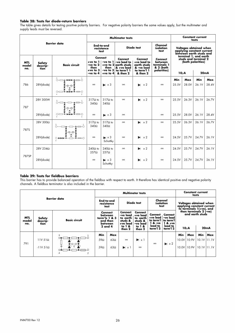
INM700 Rev 12 26
Table 28: Tests for diode-return barriers The table gives details for testing positive polarity barriers. For negative polarity barriers the same values apply, but the multimeter and supply leads must be reversed.
Barrier data
Multimeter tests Constant current tests
End-to-end resistance
testDiode test
Channel isolation
test
Connect between
terminals 1 & 2 (both polarities)
Voltages obtained when applying constant current between earth studs and
terminal 1, and earth studs and terminal 2
(both polarities)MTL model
no.
Safety descrip-
tionBasic circuit
Connect Connect Connect+ve to 1 –ve to 2
then +ve to 3 –ve to 4
–ve to 1+ve to 2
then –ve to 3+ve to 4
–ve lead toearth studs & +ve lead to term’l 1 & then 2
+ve lead to earth studs & –ve lead to term’l 1 & then 2 10µA 20mA
786 28V(diode)
3 1
4 2
∞ x 3 ∞ x 2 ∞ Min
25.5V
Max
28.0V
Min
26.1V
Max
28.4V
787
28V 300W
28V(diode)
3 1
4 2
317Ω to 340Ω
∞
317Ω to 340Ω
x 3
∞
∞
x 2 ∞
∞
25.5V
25.5V
26.3V
28.0V
26.1V
26.1V
26.7V
28.4V
787S
28V 300Ω
28V(diode)
3 1
4
317Ω to 340Ω
∞
317Ω to 340Ω
x 3 Schottky
∞
∞
x 2
x 2
∞
∞
25.5V
24.5V
26.3V
25.7V
26.1V
24.7V
26.7V
26.1V
787SP
28V 234Ω
28V(diode)
240Ω to 257Ω
∞
240Ω to 257Ω
x 3 Schottky
∞
∞
x 2
x 2
∞
∞
24.5V
24.5V
25.7V
25.7V
24.7V
24.7V
26.1V
26.1V
Table 29: Tests for fieldbus barriers This barrier has to provide balanced operation of the fieldbus with respect to earth. It therefore has identical positive and negative polarity channels. A fieldbus terminator is also included in the barrier.
Barrier data
Multimeter tests Constant current tests
End-to-end resistance
test Diode test
Channel isolation
test
MTL model
no.
Safety descrip-
tion Basic circuit
Connect between
term’ls 1 & 3 and then between 2 and 4
791 11V 51Ω
-11V 51Ω
3 1
E
4 2
Min
59Ω
59Ω
Max
63Ω
63Ω
∞
x 1
x 1
∞ ∞ x 2
Min
10.0V
10.0V
Max
10.9V
10.9V
Min
10.1V
10.1V
Max
11.1V
11.1V
Connect –ve leadto earth studs & +ve lead to 1 & then 2
Connect +ve lead to earth studs & –ve leadto 1 & then 2
Connect +ve lead to term’l 1 & –ve lead to term’l 2
Connect –ve lead to term’l 1 & +ve lead to term’l 2
Voltages obtained when applying constant current to terminals 1(+ve), and then terminals 2 (–ve)
and earth studs
10µA 20mA

INM700 Rev 12 27
APPENDIX A: ATEX certification information The Essential Health and Safety Requirements (Annex II) of the EU Directive 2014/34/EU [the ATEX Directive - safety of apparatus] requires that the installation manual of all equipment used in hazardous areas shall contain certain information. This annex is included to ensure that this requirement is met. It compliments the information presented in this document and does not conflict with that information. It is only rel- evant to those locations where the ATEX directives are applicable.
General
a) In common with all other electrical apparatus installed in hazardousareas, this apparatus must only be installed, operated and main- tained by competent personnel. Such personnel shall have under- gone training, which included instruction on thevarious types of protection and installation practices, the relevantrules and regulations, and on the general principles of area classi- fication. Appropriate refresher training shall be given on a regularbasis. [See clause 4.2 of EN 60079-17].
b) This apparatus has been designed to meet the requirements of asso- ciated electrical apparatus in accordance with EN 50020 andEN50014.
c) This apparatus has been designed and manufactured so as to pro- vide protection against all the relevant additional hazards referredto in Annex II of the directive, such as those in clause 1.2.7.
Installation a)
b)
The installation should comply with the appropriate European,national and local regulations, which may include reference to the IEC code of practice IEC 60079-14. In addition particular indus- tries or end users may have specific requirements relating to the safety of their installations and these requirements should also be met. For the majority of installations the Directive 1999/92/EC [the ATEX Directive - safety of installations] is also applicable.This apparatus is an associated electrical apparatus and is nor- mally mounted in a non-hazardous [safe] area. When mounted in a Zone1 location the apparatus must be provided with an enclosure, which offers an additional degree of protection appropriate to the area classification
c) This apparatus must not be subjected to mechanical and thermalstresses in excess of those permitted in the certification docu- mentation, this manual and the product specification. If neces- sary the product must be protected by an enclosure to preventmechanical damage.
d) The apparatus must not be installed in a position where it may beattacked by aggressive substances and must be protected fromexcessive dust, moisture and other contaniments by an enclosure.
Inspection and maintenance a) Inspection and maintenance should be carried out in accordance
with European, national and local regulations which may refer tothe IEC standard IEC 60079-17. In addition specific industries orend users may have specific requirements which should also be met.
b) Access to the internal circuitry must not be made during operation.c) If the outer enclosure of the apparatus needs to be cleaned, this
should be done with a cloth lightly moistened by a dilute mixture ofdetergent in water.
Repair a) These barriers must not be repaired. A barrier must be replaced
by an equivalent certified product.
Marking MTL700 range of barriers carry a certificate number as detailed in Table 12. Each device is also CE marked with the Notified BodyIdentification Number of 1180, and carries the following information:
a) Company logob) Company Name and Addressc) Product Number and Named) Certificate Number(s)e) Ex Classification (where applicable)f) Schematic diagramg) Safety description parametersh) Ambient temperature range
This manual applies to products date marked 2002 or later.
Figure A1: Typical MTL700 range of barrier label
Table 11: MTL700 range of Safety parameters
-
-
Model No. V Ω mA MTL702 25 200 125 MTL706 28 300 93 MTL707 28 300 93
28 - MTL707P 28 164 170
15 MTL708 28 300 93 MTL710 10 50 200 MTL710P 10 33 300 MTL715 15 100 150 MTL715P 15 50 291 MTL722 22 150 147 MTL722P 22 101 213 MTL728 28 300 93 MTL728P 28 234 119 MTL729P 28 164 170 MTL751 1 10 100
1 10 100 MTL755 3 10 300
3 10 300 MTL758 7.5 10 750
7.5 10 750 MTL761 9 90 100
9 90 100 MTL761P 9 350 25
9 350 25 MTL764 12 1k 12
12 1k 12 MTL766 12 150 80
12 150 80 MTL766P 12 75 157
12 75 157 MTL767 15 100 150
15 100 150 MTL768 22 150 147
22 150 147 MTL779 28 300 93
28 300 93 MTL796 26 300 87
20 390 51 MTL760 10 50 200
10 50 200 MTL765 15 100 150
15 100 150 MTL772 22 300 73
22 300 73 MTL778 28 600 47
28 600 47 MTL786 28 -
28 - MTL787 28 300 93
28 MTL787S 28 300 93
28 - MTL787SP 28 234 119
28 - MTL788 28 300 93
10 50 200 MTL788R 28 300 93
10 50 200 MTL791 11 51 216
11 51 216 MTL799 - - -

INM700 Rev 12 28
Model No. (V) (Ω) (mA)
Number of Maximum permissible 2 single channels cable parameters interconnected Earth1 BASEEFA (group IIC (hydrogen)) Matched
MTL7122+ 22 150 147 within the return Capacitance Inductance L/R ratio power MTL7028+ 28 300 93 Model no. hazardous area used? (µF) (mH) (µH/Ω) (W) MTL7128+ 28 300 93 MTL7128P+ 28 234 120 MTL7106/7206 1 Yes 0.083 4.1 54 0.65MTL7129P+ 28 164 171 MTL7207+ 2 Yes 0.083 4.1 54 0.65 MTL7028– 28 300 93 MTL7208+ 1 Yes 0.083 4.1 54 0.65 MTL7128– 28 300 93 MTL7122+ 1 Yes 0.165 1.66 44 0.81 MTL7162+ 10 50 200 MTL7028+/7128+ 1 Yes 0.083 4.1 54 0.65
10 50 200 MTL7128P+ 1 Yes 0.042 1.26 42 0.83 MTL7164+ 12 1k 12 MTL7028–/7128– 1 Yes 0.083 4.1 54 0.65
12 1k 12 MTL7129P+ 1 Yes – – – 1.19 MTL7167+ 15 100 150 MTL7055ac 1 Yes 1000 0.4 158 0.23
15 100 150 2 Yes 1000 0.1 79 0.45 MTL7096– 26 300 87 2 No 40 0.4 79 0.45
20 390 52 3 No 40 0.22 59 0.68 MTL7196– 26 300 87 4 Yes 40 0.035 31.25 0.92
20 390 52 MTL7056ac 1 Yes 1000 0.4 158 0.23 MTL7087+ 28 300 93 3 No 40 0.22 59 0.68
28 – MTL7060ac/7160ac 1 Yes 4.9 2.47 131 0.27 MTL7187+ 28 300 93 2 Yes 4.9 0.61 65 0.54
28 – MTL7061Pac/7161Pac 2 No 0.309 54.2 307 0.12 MTL7087P+ 28 234 120 MTL7261ac 1 Yes 4.9 3.55 158 0.23
28 – 2 Yes 4.9 0.88 79 0.45 MTL7187P+ 28 234 120 MTL7162+ 1 Yes 3.0 0.89 71 0.50
28 – 2 Yes 3.0 0.22 35 1.0 MTL7055ac 3 10 300 2 No 1.97 2.93 117 –
3 10 300 MTL7164+ 1 Yes 1.41 246 987 0.04 MTL7056ac 3 10 300 2 Yes 1.41 61.7 493 0.08
3 10 300 MTL7264ac 1 Yes 1.41 246 987 0.04 3 10 300 2 Yes 1.41 61.7 493 0.08
MTL7261ac 9 90 100 No 0.125 246 493 0.08 9 90 100 MTL7265ac 1 Yes 0.58 1.58 63 0.56
MTL7061Pac 9 350 26 2 Yes 0.58 0.4 31 1.13 9 350 26 MTL7066Pac/7166Pac 2 Yes 1.41 0.36 37 0.96
MTL7161Pac 9 350 26 MTL7167+ 1 Yes 0.58 1.58 63 0.56 9 350 26 2 Yes 0.58 0.4 31 1.13
MTL7264ac 12 1k 12 MTL7278ac 1 Yes 0.083 16.1 108 0.33 12 1k 12 2 Yes 0.083 4.02 54 0.66
MTL7066Pac 12 75 160 MTL7087+/7187+ 2 Yes 0.083 4.1 54 0.65 12 75 160 MTL7087P+/7187P+ 2 Yes 0.042 1.26 42 0.84
MTL7166Pac 12 75 160 MTL7096–/7196– 2 Yes 0.134 1.86 44 0.83 12 75 160
MT7060ac 9 75 120 9 75 120
MT7160ac 9 75 120 9 75 120
MT7265ac 15 100 150 15 100 150
MT7278ac3 28 600 4728 600 47
MT71064 28 300 93MT72064 28 300 93MT7207+ 28 300 93
28 – MT7208+ 28 300 93 MT7099 – – – MT7299 – – –

INM700 Rev 12 29
THIS PAGE IS LEFT INTENTIONALLY BLANK

INM700 Rev 12 30
THIS PAGE IS LEFT INTENTIONALLY BLANK

INM700 Rev 12 31
THIS PAGE IS LEFT INTENTIONALLY BLANK

AUSTRALIA MTL Instruments Pty Ltd, 10 Kent Road, Mascot, New South Wales, 2020, Australia
Tel: +61 1300 308 374 Fax: +61 1300 308 463 E-mail: [email protected]
BeNeLux MTL Instruments BVAmbacht 6, 5301 KW ZaltbommelThe Netherlands
Tel: +31 (0)418 570290 Fax: +31 (0)418 541044E-mail: [email protected]
CHINA Cooper Electric (Shanghai) Co. Ltd 955 Shengli Road, Heqing Industrial Park Pudong New Area, Shanghai 201201
Tel: +86 21 2899 3817 Fax: +86 21 2899 3992 E-mail: [email protected]
FRANCE MTL Instruments sarl, 7 rue des Rosiéristes, 69410 Champagne au Mont d’Or France
Tel: +33 (0)4 37 46 16 53 Fax: +33 (0)4 37 46 17 20 E-mail: [email protected]
GERMANY MTL Instruments GmbH, Heinrich-Hertz-Str. 12, 50170 Kerpen, Germany
Tel: +49 (0)22 73 98 12- 0 Fax: +49 (0)22 73 98 12- 2 00 E-mail: [email protected]
INDIA MTL India, No.36, Nehru Street, Off Old Mahabalipuram Road Sholinganallur, Chennai- 600 119, India
Tel: +91 (0) 44 24501660 /24501857 Fax: +91 (0) 44 24501463 E-mail: [email protected]
ITALY MTL Italia srl, Via San Bovio, 3, 20090 Segrate, Milano, Italy
Tel: +39 02 959501 Fax: +39 02 95950759 E-mail: [email protected]
JAPAN Cooper Crouse-Hinds Japan KK, MT Building 3F, 2-7-5 Shiba Daimon, Minato-ku, Tokyo, Japan 105-0012
Tel: +81 (0)3 6430 3128 Fax: +81 (0)3 6430 3129 E-mail: [email protected]
NORWAY Norex AS Fekjan 7c, Postboks 147, N-1378 Nesbru, Norway
Tel: +47 66 77 43 80 Fax: +47 66 84 55 33 E-mail: [email protected]
RUSSIA Cooper Industries Russia LLC Elektrozavodskaya Str 33 Building 4 Moscow 107076, Russia
Tel: +7 (495) 981 3770 Fax: +7 (495) 981 3771 E-mail: [email protected]
SINGAPORE Cooper Crouse-Hinds Pte Ltd No 2 Serangoon North Avenue 5, #06-01 Fu Yu Building Singapore 554911
Tel: +65 6645 9864 / 6645 9865 Fax: +65 6 487 7997 E-mail: [email protected]
SOUTH KOREA Cooper Crouse-Hinds Korea 7F. Parkland Building 237-11 Nonhyun-dong Gangnam-gu, Seoul 135-546, South Korea.
Tel: +82 6380 4805 Fax: +82 6380 4839 E-mail: [email protected]
UNITED ARAB EMIRATES Cooper Industries/Eaton Corporation Office 205/206, 2nd Floor SJ Towers, off. Old Airport Road, Abu Dhabi, United Arab Emirates
Tel: +971 2 44 66 840 Fax: +971 2 44 66 841 E-mail: [email protected]
UNITED KINGDOM Eaton Electric Limited, Great Marlings, Butterfield, Luton Beds LU2 8DL
Tel: +44 (0)1582 723633 Fax: +44 (0)1582 422283 E-mail: [email protected]
AMERICAS Cooper Crouse-Hinds MTL Inc. 3413 N. Sam Houston Parkway W. Suite 200, Houston TX 77086, USA
Tel: +1 281-571-8065 Fax: +1 281-571-8069 E-mail: [email protected]
Eaton Electric Limited, Great Marlings, Butterfield, Luton Beds, LU2 8DL, UK. Tel: + 44 (0)1582 723633 Fax: + 44 (0)1582 422283 E-mail: [email protected] www.mtl-inst.com
© 2017 Eaton All Rights Reserved u Publication No. INM700 Rev 12 170117
EUROPE (EMEA): +44 (0)1582 723633 [email protected]
THE AMERICAS: +1 800 835 7075 [email protected]
ASIA-PACIFIC: +65 6 645 9888 [email protected]
The given data is only intended as a product description and should not be regarded as a legal warranty of properties or guarantee. In the interest of further technical developments, we reserve the right to make design changes.