instruction manual - beastxwiki.beastx.com/images/3/37/microbeast_plus_version_4.x.x_en.pdf · d -...
TRANSCRIPT

MICROBEAST PLUS Version 4.x.xInstruction manual

ContentsIntroduction 1
Box content and accessories 5
MICROBEAST PLUS HD 8
Preliminary steps 10
Receiver installation 14
Optional features explanation 18
Receiver setup menu 21
A - Receiver type (signal input) 22B - Channel to function assignment 23N - Throttle failsafe position 27
Setup menu 29
A - Mounting orientation 31B - Swashplate update rate 32C - Tail servo center pulse 34D - Tail servo update rate 36E - Tail servo limits 39

F - Tail gyro direction 41G - Swashplate servo trim 42H - Swashplate mixing type 46I - Swashplate servo directions 48J - Swashplate servo throw 49K - Swashplate pitch adjustment 52L - Swashplate cyclic limit 53M - Swashplate gyro directions 54N - RPM Governor mode 56
Parameter menu 57
A - Quick trim 59B - Control style 61C - Speed flight stability 62D - Rudder rate consistency 63E - Stick deadzone 65F - Torque precompensation 66G - Pitch pump 67H - Cyclic repsonse 68I - Throttle response 69J - Slow rampup speed 70K - Fast rampup speed 71L - AttitudeControl mode 72M - AttitudeControl pitch 75

Governor setup menu 77
A - Test mode 78B - Throttle low position 84C - Throttle high position 85D - Switch point display 86E - Signal divider 93F:G:H - Main gear ratio 95
Flying and optimization 97
Usage of RPM Governor (optional) 102
Usage of AttitudeControl (optional) 103

1
Introduction
MICROBEAST PLUS - What is this?MICROBEAST PLUS is the official successor of the famous MICROBEAST flybarless system. In comparance to MICROBEAST the hardware has been revised thoroughlyto be on par with the state of the art. Latest MEMS sensors and faster processing gives a more precise control in all flight situations. At the moment MICROBEAST PLUScan only be used in combination with RC model helicopters. Different application types will be available soon.If you have MICROBEAST already in use you will find that the setup of MICROBEAST PLUS runs as usual. The proven „EasySetup“ concept and ease of use ismaintained. So upgrading to MICROBEAST PLUS is very easy. As MICROBEAST PLUS is much more powerful than MICROBEAST, it is specifically tailored for usewith the StudioX software solution that enables more complex adjustment processes thus resulting in completely new applications. We recommend to visit this wiki and oursupport website [1] from time to time to get the latest features for your MICROBEAST PLUS.At the moment we offer two additional features for the device, the RPM governor and the AttitudeControl function. All MICROBEAST PLUS units can be upgraded withthese functions by paid software update. Additionaly these functions are already included in ProEdition devices.
Firmware version display
Please note that these instructions are only valid for the MICROBEAST PLUS firmware version 4.x.x!
The firmware version can be detected by connecting the unit to a computer by using the USB2SYS interface together with the StudioX software bundle .Also you candirectly read on the MICROBEAST PLUS unit during the initialization phase what firmware version your MICROBEAST PLUS is running: MICROBEAST PLUS firstcarries out a brief LED test by lighting up all Menu-LEDs simultaneously, and cycling the Status-LED color (red->blue->purple). Then for about 3 seconds, the Status-LEDlights red while the Menu-LEDs A to G display the first digit of the firmware version, and the LEDs H to N the second digit of the firmware version. By briefly pushing thebutton you can get more version informations displayed. In respect to the manual this information is not important.

2
Firmware version 4.0.x
In the left row menu LED C shows the major version „4“.In the row from LEDs H to N nothing lights up. So minor version is „0“.
Safety notes
Radio controlled (R/C) helicopters are no toys! The rotor blades rotate at high speed and pose potential risk. They may cause severe injury due to improper usage. It isnecessary to observe common safety rules for R/C models and the local law. You can gather information from your local R/C model club or from your national modelersassociation.
Pay attention to your own safety and the safety of other people and property in your vicinity when using our product. Always fly in areas away from other people. Neveruse R/C models in close proximity to housing areas or crowds of people.R/C models may malfunction or crash due to several reasons like piloting mistakes or radio interference, and cause severe accidents. Pilots are fully responsible for theiractions, and for damage or injuries caused by the usage of their models.
Please read the instruction manual thoroughly before the first use of your MICROBEAST PLUS and setup the system carefully according to this manual. Allowsufficient time for the setup procedure and check each step carefully. Watch for a mechanically clean and proper build of your helicopter. A wrong system setup can lead to aserious accident and damage to the model.
3
Radio controlled (R/C) models consist of several electrical components. It is therefore necessary to protect the model from moisture and other foreign subtances. If themodel is exposed to moisture this may lead to a malfunction which may cause damage to the model or a crash. Never fly in the rain or extremely high humidity.
When operating the helicopter with a MICROBEAST PLUS ensure there is a sufficiently large and stable receiver power supply. Because of the direct coupling of therotor blades to the servos, without the use of a flybar mixer, the servos are exposed to increased actuating forces. In addition, because of the intermediary electronic gyrosystem, the servos are driven more often than with traditional use. These factors can make the power consumption increase a lot compared to a flybar helicopter. When thesupply voltage falls below 3,5 volts for a short amount a of time, the system will power off and reboot. In this case a crash of the helicopter is unavoidable.
Do not expose the MICROBEAST PLUS system to extreme variations in temperature. Before powering up the system, wait some time so that the electronics canacclimatize and any accumulated condensation is able to evaporate.
The sensors of MICROBEAST PLUS consist of highly sensitive electromechanical components. These can be damaged due to moisture or mechanical or electricalimpact. Do not continue using this product if it has been exposed to such influences, e.g. due to a crash of the model or due to overvoltage caused by a defective receiverpower supply. Otherwise a failure may happen any time.
When operating electric helicopters make sure that the electric motor cannot start inadvertently during the setup procedure. Particularly pay attention if using asingle-line receiver and if the ESC is connected directly to the MICROBEAST PLUS. We recommend disconnecting the electric motor from the ESC during the setupprocedure. Prior the first usage please slide the motor/pinion away from the main gear, then check that the motor does not to start inadvertently when the receiver is switchedon.
When operating the RPM Governor feature of MICROBEAST PLUS it is essential to ensure that the motor cannot start by accident when making adjustment orperforming preparations to start the engine. Carefully read this manual and make sure you fully understand how the RPM Governor feature is operated before making anyadjustments. Also make sure the motor does not start when the radio link is interrupted or when you switch on the transmitter initially. With electric driven models do notdock the motor to the main gear unless all necessary adjustment procedures have been finished. Always maintain sufficient safety distance to the motor and other rapidlyrotating components of the helicopter.
MICROBEAST PLUS with AttitudeControl can be used as a flying aid for beginners by limiting the reaction of the helicopter to stick inputs and by stabilizing thehelicopter with a electronic control loop. However, this does not provide that the helicopter can always be flown safely! By incorrect control inputs the helicopter still maycrash or be placed in a position in which the pilot becomes disoriented even when using AttitudeControl. In addition, the helicopter can drift due to external influences and itis not guaranteed that the artificial horizon of the device can stabilize the helicopter at any time and recover from any orientation. Influences such as temperature fluctuationsor vibrations may cause incorrect results and distort the position calculation of the system in consequence. There is no guarantee that the system will always work correctly.Only the pilot is responsible for the control of the helicopter and thus also for the use of the system. Note that the system for technical reasons will not hold the helicopterabsolutely to the point. The unstable tendency of a helicopter will cause the model to fly in a certain direction even when using AttitudeControl. External influences such aswind can further strengthen this effect. In addition measurement inaccuracies of the sensors can distort the position determination slightly. You must always be able to turnoff the system immediately and be able to take over full control of the helicopter.

4
We suggest you to seek the support of an experienced helicopter pilot before you undertake the first flight of your model. Additionally, flight training with a R/Csimulator can help make flying easier and more enjoyable. Ask your local dealer if you need technical support or if you observe problems during the usage of our system.
AttitudeControl can help to facilitate flying of model helicopters by briefly passing over control to the system if the pilot becomes disoriented. By using the built-inartificial horizon the helicopter can be brought to a nearly horizontal position so that the pilot gains time to reorient. Thus, there can be no assurance that the model is savedfrom a crash in general. Depending on the current attitude and the speed of the model and depending on how fast the AttitudeControl is activated, the model may crash beforeor while the system tries to recover. In addition, the helicopter can drift due to external influences and it is not guaranteed that the artificial horizon of the device can stabilizethe helicopter at any time and recover from any orientation. Influences such as temperature fluctuations or vibrations may cause incorrect results and distort the positioncalculation of the system in consequence. Strictly observe the general safety rules for dealing with RC models and do not totally rely on the system. The pilot is responsiblefor the control of the helicopter and thus also for the use of the system. You must always be able to turn off the system immediately and be able to take over full control ofthe helicopter.
5
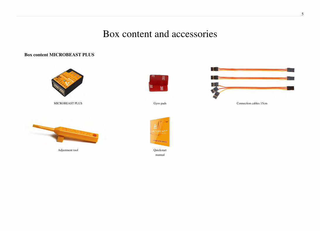
Box content and accessories
Box content MICROBEAST PLUS
MICROBEAST PLUS Gyro pads Connection cables 15cm
Adjustment tool Quickstartmanual

6
Box content MICROBEAST PLUS HD
MICROBEAST PLUS HD Gyro pads Connection cables 15cm
Power connector Power switch Adjustment tool
Quickstart manual

7
Optional accessories
Connection cables8cm
USB2Sys PCInterface
Spektrum remote satellite adapter
Adapter for RPM sensors RPM sensor for brushless motors

8
MICROBEAST PLUS HDThe operation of MICROBEAST PLUS HD is identical to MICROBEAST PLUS apart from the high power supply and the switch system. So it is not explicitly dealt withthe HD version later on in this manual. All subsequent executions are also based on MICROBEAST PLUS HD!
Introduction to MICROBEAST PLUS HDMICROBEAST PLUS HD is the most powerful flybarless system from the MICROBEAST series. While function and operation are identical to MICROBEAST PLUS, theHD version is characterized by the possibility of a high power supply. This meets the requirements of speed flyers and extreme 3D pilots and is primarily used in helicopterslarger than 500 size that have very power consuming servos installed.By using a low-resistance high-current connector system MICROBEAST PLUS HD makes it possible to use thick power cables for connecting receiver battery or BECwhich preserves a virtually loss-free transfer of electric current. In addition the power connection is switchable using a particularly fail-safe switch system, so there is no needfor a separate and costly power switch. The input voltage range is 3.5 to 8.4 volts.
Solder to the supplied power cable a matching counterpart for the supply battery used or connect it with the BEC power wires (of your speed controller). When using abattery it is not recommended to directly connect the battery to the MICROBEAST PLUS HD without using the supplied power cable as an adapter. Continuous pluggingand unplugging can cause the overlying servo plugs getting unplugged accidentally or cause the adhesive gyro pad to get loose! Receiver and servo plugs are connected tothe ports on top of the unit. There is no difference between HD and non HD version in this respect.The use of the electronic switching system is optional. The switch is designed in a way so that it interrupts the power circuit by shorting the switch circuit in OFF position.If the switch is not connected MICROBEAST PLUS HD is switched on permanently as soon as the power is connected.Please note:

9
• Using the high power connection port is not a must. You can also use MICROBEAST PLUS HD in a conventional manner by powering the unit from the receiver ports inthe top row, as shown in the chapter on receiver installation. However, using the electronic power switch system is not possible then!
• The electrical connections of the high power connection port and the upper terminal row form a parallel power circuit during operation. So it is possible to connect anadditional power source at the upper terminal row. For example this can be a buffering battery or a backup system that shall protect against failure of the primary powersource. In this case note the manufacturer‘s instructions, if this is possible and permissible for the supply systems used. Also note that using the electronic power switchsystem of MICROBEAST PLUS HD is not possible in this combination!
•• Note that the system can only be as powerful as the power source allows. Use power cables with sufficient diameter, avoid long cable length and only use a plug systemfor connection of battery and power cable that is capable of transferring high currents.
•• MICROBEAST PLUS HD does not supply an internal voltage regulation! The voltage that is applied to the high power connection port will directly be passed to the servoand receiver connections. Only use electronic components (servos and receiver) that are designed for your power source.
MICROBEAST PLUS HD will draw a very low amount of current even when the system is switched off. Therefore always completely disconnect the battery fromthe system if you do not use the model for a extended period of time to prevent the supply battery from getting discharged and damaged in consequence.

10
Preliminary steps
Mounting the Microbeast PLUS unitAttach the Microbeast PLUS unit by using one of the provided 3M® gyropads at a preferably low vibrating position on your helicopter such as the gyro platform or receiverplatform. You may need to choose another type of mounting pad depending on the vibration pattern of your helicopter. For more information please ask you MicrobeastPLUS dealer.The MICROBEAST PLUS unit can be attached flat or upright on the helicopter. However, the servo connector pins must always point towards the front or rear of thehelicopter. The small white sensor pinboard on the side must always be inline with flight direction.
Pay attention that the edges of the Microbeast PLUS unit are all parallel with the corresponding rotational axes of the helicopter! Especially make sure that themounting platform is perpendicular to the main shaft! On the other hand it is not important that the unit is directly placed on the rotation axis (which is nearly impossible).

11
There are eight possible mounting orientations:
flat, cover on top, servo connectors showing tofront
upright, button on top, servo connectors showing tofront
flat, cover showing to bottom, servo connectorsshowing to front
upright, button on bottom, servo connectorsshowing to front
12
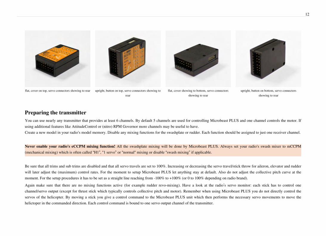
flat, cover on top, servo connectors showing to rear upright, button on top, servo connectors showing torear
flat, cover showing to bottom, servo connectorsshowing to rear
upright, button on bottom, servo connectorsshowing to rear
Preparing the transmitterYou can use nearly any transmitter that provides at least 6 channels. By default 5 channels are used for controlling Microbeast PLUS and one channel controls the motor. Ifusing additional features like AttitudeControl or (nitro) RPM Governor more channels may be useful to have.Create a new model in your radio‘s model memory. Disable any mixing functions for the swashplate or rudder. Each function should be assigned to just one receiver channel.
Never enable your radio‘s eCCPM mixing function! All the swashplate mixing will be done by Microbeast PLUS. Always set your radio‘s swash mixer to mCCPM(mechanical mixing) which is often called “H1”, “1 servo” or “normal“ mixing or disable “swash mixing” if applicable.
Be sure that all trims and sub trims are disabled and that all servo travels are set to 100%. Increasing or decreasing the servo travel/stick throw for aileron, elevator and rudderwill later adjust the (maximum) control rates. For the moment to setup Microbeast PLUS let anything stay at default. Also do not adjust the collective pitch curve at themoment. For the setup procedures it has to be set as a straight line reaching from -100% to +100% (or 0 to 100% depending on radio brand).Again make sure that there are no mixing functions active (for example rudder revo-mixing). Have a look at the radio’s servo monitor: each stick has to control onechannel/servo output (except for thrust stick which typically controls collective pitch and motor). Remember when using Microbeast PLUS you do not directly control theservos of the helicopter. By moving a stick you give a control command to the Microbeast PLUS unit which then performs the necessary servo movements to move thehelictoper in the commanded direction. Each control command is bound to one servo output channel of the transmitter.
13
Other functions such as throttle curves, ESC switches or auxiliary functions can be adjusted as usual. When using the RPM Governor function the throttle adjustment will bedescribed later. Also the switch assignment for AttitudeControl will discussed at the specific topic.
Always make sure that the motor in electric models can not start when doing the adjustment work! If the drive battery is used as power supply for receiver, servosand Microbeast PLUS, disconnect the motor from the ESC.

14
Receiver installationTo control your helicopter with MICROBEAST PLUS you have the opportunity to use different receiver types. Basically it is distinguished between (conventional)„Standard“ receivers and „Single-Line“ (or „sum signal“) receivers.
Standard receiversA standard receiver is a receiver that is connected to MICROBEAST PLUS by using the single servo outputs of the receiver and connect them to the five control channels ofMICROBEAST PLUS. The channel which determines the controlled function simply is selected by inserting each plug to the correct output at the receiver.
The designation Spektrum®/Futaba® is only exemplary. You can use any radio system with at least 6 output channels to connect to MICROBEAST PLUS. For finding outhow to connect the wires to MICROBEAST PLUS have a look at your radio's servo monitor and refer to the radio's instruction manual.
Ensure a tight fit of the connectors. The pin board of MICROBEAST PLUS is designed so that the plugs firmly clamp each other when they are fully inserted. Anyhow,especially when using a single-line receiver, it is possible that connectors are plugged in with no adjacent neighbors. Such plugs should additionally be secured againstloosening.
Single-Line receiversWith a single-line receiver all channels (control functions) are transmitted by one single connection line to MICROBEAST PLUS. This is done by packing all channel outputdata to a digital data paket or by chaining the servo signals to one output port. Because of this, it is not possible here to assign functions by inserting the appropriate plugs inthe receiver. Instead you have to assign the function ordering by software in the MICROBEAST PLUS receiver setup menu, so that the unit "knows" what control functioneach incoming channel is used for.

15
There are single-line receivers available that supply additional single channel connectors/servo outputs similar to a standard receiver. In combination with MICROBEASTPLUS you only have to treat such receivers as single-line receivers if you really use the single-line function. If you connect the receiver by using the standard 5-plug layout,such receiver has to be considered as "standard" receiver in the following and as shown above.
In general the single-line connection wire is plugged into the [DI1] input of MICROBEAST PLUS. When using the signal of a single Spektrum® remote satellite you mustconnect the optional available Spektrum® satellite adapter (Order Nr. BXA76009) in between, in order to supply the remote satellite with the correct voltage level (figure 3).The throttle servo or ESC is connected to the [CH5] output. When using a speed controller with BEC, from here the power will be distributed to receiver and servos.Alternatively or additionally you can connect a power supply/second BEC wire/buffering battery to the [SYS] port. Note that all plus and minus connectors are bridgedon the MICROBEAST PLUS. Only at the triple input/output [AUX|PIT|RUD] you musn't connect any power source as this is not part of the power rail! Whenusing a big heli with standard size servos it may be insufficient to only provide power at the [SYS] port! If there are no other ports left to (additionally) feed in power, wehighly recommend using the MICROBEAST PLUS HD with separate high power input.Using a single-line receiver with additional servo output ports you can choose between connecting throttle servo/ESC and additional devices to MICROBEAST PLUS (figure1) or directly to the receiver (figure 2). But note that when connecting the power supply at the receiver, MICROBEAST PLUS and the servos will only be supplied over thesmall single-line connection. Especially on big helis with standard size servos this might not be sufficient! Here it is mandatory to connect some supply lines in parallel toother free ports, such as [SYS] or [CH5] or better connect the power supply (i.e. ESC with BEC supply) directly to the MICROBEAST PLUS as shown in figure 1.
Figure 1 - Typical wiring layout for single-line receivers Figure 2 - Alternative wiring layout for single-line receiver withadditional servo output channels
Figure 3 - Spektrum® remote satellite connection with poweradapter
Ensure a tight fit of the connectors. The pin board of MICROBEAST PLUS is designed so that the plugs firmly clamp each other when they are fully inserted. Nevertheless, especially when using a single-line receiver, it is possible that connectors are plugged in with no adjacent neighbors. Such plugs should additionally be secured

16
against loosening.
Receiver bindingBefore using your receiver with MICROBEAST PLUS make sure that the receiver is bound to the transmitter and that it is sending output data on the servo outputs and/orsingle-line port. Please refer to the manual of your radio system to find out how binding procedure is performed with your specific system. Also check if there is the need toperform special settings to enable the single-line data output of the receiver in case you intend to use this output port in combination with MICROBEAST PLUS.Only in the case of using a single Spektrum® satellite receiver that is directly connected to MICROBEAST PLUS, this is bound by the aid of MICROBEAST PLUS as thereis no other option to enable binding procedure at the receiver. Even more, here it is very important to bind the receiver first before programming MICROBEAST PLUS andthis step must be performed, even if the satellite was already in use elsewhere (e. g. in connection with a “Standard” Spektrum® receiver) and was already bound to thetransmitter earlier.
Watch out that the motor can not start accidentally when using the BEC of your speed controller to power the unit!
Simultaneously with the binding process, the type of satellite receiver has to be set, i.e. whether it is a DSMX or DSM2 satellite (The actual selected signal protocolin the transmitter is not relevant!). It is very important to choose the correct type of satellite receiver here, since an improper setting may seem to work but canlead to radio interference or total loss of the link in the subsequent operation!
Insert a Spektrum® “Bind Plug” at the [SYS] port of MICROBEAST PLUS. In case the power is supplied exclusively at the [SYS] connection, to bind a Spektrum® satellitereceiver the power supply must be provided temporarily through any of the other ports [CH1] - [CH5]. To select a DSM2 satellite and to enter bind mode, simply switch onthe power supply now. The LED on the receiver and LED N on MICROBEAST PLUS will start to flash. You can bind the transmitter as usual (for more information refer tothe instructions of your radio control system). To select and bind a DSMX satellite, hold down the button on MICROBEAST PLUS while switching on the power supply.Now the receiver‘s LED and LED H (!) on the MICROBEAST PLUS will flash and you can release the button and bind the receiver with your transmitter. After successfulbinding procedure the receiver‘s LED will stay solid. LED H respectively N flash alternately to all other LEDs. Now switch off the power supply and remove the bind plug.Continue with receiver type setup in the next step.

17
Note:
•• Decisive for the selection alone is, which type of satellite receiver is plugged in! It is irrelevant which transmission method between the receiver and transmitter is actuallyused. Check carefully what type of receiver you have and what type you setup. An incorrect setting is not obvious but will lead to malfunction or failure of the radio linklater in use.
• It makes no difference if you pull off the “Bind Plug” during the binding process or leave it connected as you would expect from some “standard” Spektrum® receivers!

18
Optional features explanationAt the moment we offer two additional features for MICROBEAST PLUS: the RPM Governor and the AttitudeControl function. All MICROBEAST PLUS units can beupgraded with these functions by (paid) software update. Additionaly these functions are already included in ProEdition devices.With MICROBEAST PLUS you have purchased an electronic control system that continuously detects and controls the commands from the pilot. As a result the system isconstantly aware of how the drive system will be burdened. The RPM Governor system uses this advantage to control the motor rpm. Contrary to conventional motorcontrol systems that only monitor the engine speed, MICROBEAST PLUS can thus react sooner to speed changes. A separate engine governor system is no longer requiredfor nitro helicopters and electric models can be used with a simple (cheap) speed controller without additional features such as soft start or governor mode. The desired rotorspeed is specified via the remote control transmitter and MICROBEAST PLUS controls the throttle servo or speed controller accordingly, so that the predetermined headspeed is maintained from takeoff to landing. MICROBEAST PLUS offers an integrated soft start for spooling up the rotor before takeoff and a quick start to regain headspeed in a controlled manner when practicing autorotation maneuvers. The system is suitable both for electric and nitro/gas helicopters. Using the proven „Easy Setup“concept no additional equipment is required for programming (apart from your remote control system) and the initial setup is done within minutes.Note: The RPM Governor function can only be used in combination with a single-line receiver or Spektrum remote satellite. When using a receiver with standard connectionlayout there is no option for connecting the rpm sensor and throttle servo/ESC and no connector for throttle control.With AttitudeControl MICROBEAST PLUS can determine the absolute position in space of the helicopter on the roll and pitch axis, regardless of the position in which thehelicopter is currently located. At the moment this can be used as flying aid with five different operation modes:•• Bail out rescue mode (with/without collective pitch)• 3D – Mode (with/without collective pitch)•• Flight trainer modeAttitudeControl helps you to learn new maneuvers and reduces the probability of crashing significantly. If AttitudeControl is switched on in flight the helicopter will beoriented in a nearly horizontal position, depending on the selected mode always in normal or also in inverted flight. So the helicopter can be brought in a save position by thepress of a button, i. e. if the pilot becomes disoriented. Beginners can use AttitudeControl permanently (preferably in the „Flight trainer mode“), whereby the helicopter losesthe peculiarity of having to be constantly controlled by the pilot. While AttitudeControl is switched on the pilot can simply release the sticks for aileron and elevator and thehelicopter will be held almost horizontally without external control commands.

19
Preparations for RPM Governor usage (optional)To use the RPM Governor function of Microbeast PLUS it is necessary that Microbeast PLUS is able to measure the motor speed. Therefor the separate purchase of a motorrpm sensor is required. Additionaly you need the rpm sensor adapter cable (Order Nr. BXA76401) to be able to connect the sensor to your Microbeast PLUS unit and powerit from there. When using an electric helicopter it is possible that your speed controller already supplies a rpm signal output. In this case no additional accessories arerequired as you can directly connect this signal wire's connector to the front pin board of Microbeast PLUS.When using a nitro helicopter remove the servo horn of the throttle servo before powering up the system or do not connect the throttle servo linkage yet, in order to avoidblocking and in consequence damage of the servo due to incorrect setting.Using an electric model ensure that the speed controller is programmed correctly and that the travels for the throttle channel have been adjusted in the transmitter ifnecessary. Note that the speed controller itself must not be operated in a (heli specific) governor mode, but must be operated in a simple motor control mode thatallows to control the motor rpm as direct as possible. The throttle signal must not be filtered by the ESC and should be processed as linear as possible. This ensures thatthe control loop of Microbeast PLUS can govern the motor rpm optimally. Also you should switch off any "soft start" function, as this will be done by Microbeast PLUS.Some electric speed controllers offer a special „External control mode“ or „Flybarless mode“ which meet these requirements. If your motor controller does not have such amode, we recommend to select a mode that typically offers such behavior, like a some mode for fixed wing aircraft. Note, however, that no brake function (which is requiredfor electric gliders) must be active and that the throttle response should be set to maximum speed, if such a feature is provided.
Pay attention to your own safety and the safety of other people and property in your vicinity when using our product. When using helicopters with nitro/gas enginesmake sure that the motor will not start when making adjustments to the system. When using a gas engine always keep the ignition system deactivated!
For electric helicopters remove the motor pinion from the main gear during initial setup. Warning! Risk of injury! Never touch the motor when it‘s running. Alwayskeep a save distance to all rotating parts of the helicopter.
Operating principles of AttitudeControl (optional)When the term „AttitudeControl“ is used in the further course, in general reference is made to the function of the artificial horizon, irrespective of a particularoperating mode such as „Bail out rescue mode“, „3D – Mode“ or „Flight trainer mode“.
AttitudeControl can be enabled or disabled via Parameter menu point L by selecting one of the operating modes as mentioned above. Only if AttitudeControl is enabled, i.e.one of the five operating modes is selected, then AttitudeControl can be activated in operation via the remote control transmitter. Enable/disable and activate/deactivate aretherefore to separate conceptually!For the use of AttitudeControl it is strongly recommended to use a single-line receiver, since for activating AttitudeControl in flight an additional control channel is needed.Almost every manufacturer of remote control systems offers such a receiver for his system and Microbeast PLUS supports almost all types of single-line protocols. Theadditional control channel allows to activate AttitudeControl before, during and after the flight via the remote control transmitter, so that the helicopter is stabilizeddepending on the selected operating mode if required. As long as AttitudeControl is deactived the helicopter can be flown as usual and Microbeast PLUS solely works as
20
flybarless stabilization system. Preferably use a switch or push button on the transmitter that actuates the specific channel for activation/deactivation and that is safe and easyto reach.Alternatively, the already existing channel for the tail gyro gain can be used to additionally switch AttitudeControl on and off, e.g. if a standard receiver is used (here only 5channels can be plugged into Microbeast PLUS) or a transmitter with only six channels is used. This alternative, however, is far less convenient as it may require somecomplex programming of the transmitter, especially if several flight modes are programmed with different tail gyro sensitivity settings on the transmitter.

21
Receiver setup menuDue to the possibility of connecting very different types of receivers with different types of signal output to MICROBEAST PLUS, you must choose the receiver type in thereceiver setup menu. Additionally when using a single-line receiver it is mandatory to define the function assignment to the receiver output channels, as typically on thesingle-line receiver the channel ouput data is packed together and therefore it is not clear, which channel controls which stick function.To get into the Receiver menu press the button on MICROBEAST PLUS and hold it down while turning on the receiver power supply. The yellow Menu-LED A should nowbe flashing instantly. Release the button.
When you entered Receiver setup menu correctly, the Menu LED A will flash instantly and the Status LED may show some color to indicate the currently selected receivertype. Proceed with receiver type setup as described for Receiver setup menu point A. When you see all MENU LEDs lighting up and/or Status LED is changing colors youdid not hold down the button before powering up and MICROBEAST PLUS started with standard initialization procedure! In this case power off and try again.
If you use a speed controller with BEC, disconnect the motor to avoid unintentional starting of the engine! For a heli with combustion engine you should removethe servo horn from the throttle servo.

22
Note that in the first menu points of Receiver setup menu no control signal is emitted on CH5 Output of MICROBEAST PLUS, in case you are using a single-line receiver.At menu point N (Throttle failsafe setting) the output is activated though to check throttle position!
A - Receiver type (signal input)At Receiver setup menu point A color and state of the Status-LED give you information about which type of receiver/transmission protocol is currently selected. In order tochange the type, press and hold the button for about 2 seconds. The Status-LED will light in the next color and flash eventually. Repeat this as many times as required untilthe Status-LED matches your receiver type/transmission protocol:
Status-LED Receiver type/Transmission protocol
off Standard receiver
purple Single Spektrum® satellite
red flashing Futaba® S-BUS
red SRXL
blue flashing PPM composite signal
• Standard receiver is any receiver that is connected to MICROBEAST PLUS using the standard servo output ports on the receiver and connecting these to the functioninput ports on MICROBEAST PLUS using the five connection cables. Also see the topic Receiver installation.
• Choose Single Spektrum® satellite only when you have connected one single Spektrum® remote satellite directly to the [DI1] port of MICROBEAST PLUS using theoptional available Spektrum® satellite adapter (Order Nr. BXA76009). If using a conventional Spektrum® receiver that is connected with multiple wires toMICROBEAST PLUS please select option Standard receiver.
• When using the S-Bus signal of a Futaba® S-BUS receiver make sure the signal output of the receiver is setup correctly. Newer Futaba® receivers allow to configure thesignal outputs differently and also may have different ports for S-Bus2 and S-Bus1. In this case make sure to use the S-Bus1 signal!
• SRXL is a data format that is used by different manufacturers of radio systems and that is sometimes designated differently. Please see this site for further information.Choose SRXL when using the single-line signal of one of the following receivers: JETI receivers with UDI serial output mode (not PPM), JR receivers with XBUS ModeB output, Multiplex M-Link receivers with SRXL output, BEASTRX receivers with SRXL output, GRAUPNER HOTT receivers with SUMD output (not SUMO!),Spektrum AR9020 receivers with SRXL output (only with special MICROBEAST PLUS firmware!)
• PPM composite signal is used for receivers with analog sum signal output. Here the analog servo position data is simply transferred in one long chain of servo pulses. Note that depending on the number of transferred channels this chaining process can cause the transfer take more time than when processing data from the single servo

A - Receiver type (signal input) 23
outputs in Standard receiver configuration. Therefore it is not recommended to use such configuration as the control might feel delayed. If the receiver allows to switchbetween different modes better use a digital sum signal like SRXL or S-Bus. Exemplary the following receivers send out a PPM composite signal: JETI receivers withPPM serial output mode, robbe/Futaba® R6007/R6107 receivers, Graupner HOTT receivers with SUMO output mode.
Press the button, but only briefly, to save the setup and switch to Receiver setup menu point B (the yellow Menu-LED B will flash) in case you selected a single-linereceiver. If the selected receiver type is “Standard” the setup is finished now and briefly pushing the button will complete receiver setup (all LEDs flashing). Channelassignment (Menu point B and following) is not necessary and not provided since the allocation takes place by appropriate insertion of the cables into the receiver's servooutput ports.If you have already briefly pressed the button by mistake and it did not change the receiver type but switch to Menu point B or end of menu, then simply switch off powerand repeat the above procedure.
B - Channel to function assignmentIf not a standard receiver but a single-line receiver was selected at menu point A, it must be established which control function is controlled by what channel. This isnecessary because all the control functions are transmitted via one single line and virtually every manufacturer uses his own order in the arrangement of channels to controlfunctions. There is no possibility of plugging the cables in each individual channel matching, like it is with a standard receiver.
Preset channel assignmentFor each specific type of single-line receiver selected at menu point A there is an appropriate type of receiver channel allocation saved in MICROBEAST PLUS. Please referto the tables below. Use the column that represents your receiver type and the Status-LED color that was set at menu point A and check if your radio transmits the channels inthe defined order respectively each stick function on the radio is transmitted using the specified channel number on the left. To know the channel assignment of yourtransmitter you can check the user manual of the transmitter or look at the servo monitor of the transmitter if it has this feature. If in doubt ask the manufacturer of yourtransmitter.

B - Channel to function assignment 24
Spektrum®Satellite
Futaba®S-BUS SRXL
BEASTRX Multiplex® Graupner®SUMD
Spektrum®SRXL
PPM compositesignal
Channel*1 Throttle Aileron Aileron Aileron Collective Throttle Collective
2 Aileron Elevator Elevator Elevator Aileron Aileron Aileron
3 Elevator Throttle Throttle Rudder Elevator Elevator Elevator
4 Rudder Rudder Rudder Collective Rudder Rudder Rudder
5 Tail gyro Tail gyro Tail gyro Throttle AttitudeControl** Tail gyro AttitudeControl**
6 Collective Collective Collective Tail gyro Throttle Collective Throttle
7 AttitudeControl** AttitudeControl** AttitudeControl** AttitudeControl** Tail gyro AttitudeControl** Tail gyro
8 RPM Governor*** RPM Governor*** RPM Governor*** RPM Governor*** RPM Governor*** RPM Governor*** RPM Governor***
9 CH6 Output CH6 Output CH6 Output CH6 Output CH6 Output CH6 Output CH6 Output
*Channel designation of Spektrum® transmitters:
1 2 3 4 5 6 7 8 9
THROTTLE AILERON ELEVATOR RUDDER GEAR AUX1 AUX2 AUX3 AUX4
**AttitudeControl only applicable with MICROBEAST PLUS ProEdition firmware. When using a different firmware this channel by default controls CH6Output.***Only applicable when RPM Governor feature is installed. Please note that the separate RPM Governor control is only used for nitro helicopters. The RPMGovernor for electric helis always uses the throttle channel for governor control.To load the preset channel assignment wait until the Status-LED lights blue and then hold down the button for several seconds. The yellow Menu-LED will immediatelyjump to Receiver menu point N.

B - Channel to function assignment 25
In case the ordering differs from the given tables, you have to manually assign the channel order step by step. How this works is described below.• If the Status-LED stays red at menu point B, this means that there is no valid remote control signal available. A channel assignment in this case is impossible! Check if
the receiver is properly bound to the transmitter and that a receiver/transmission protocol of the correct type is selected in Receiver menu point A. Switch off the powerand restart the receiver type setup procedure from the beginning.
•• You can also load the default assignment by pushing the button for several seconds in any of the following points for function assignment. This will erase all previouslymade individual assignments.
Teaching of customized channel orderIf you need a customized channel order, please first prepare your transmitter as described here. Additionally make sure that each control function of your transmitter activatesone and only one channel, for example by using the servo monitor of your transmitter. This can be tricky especially for throttle/collective pitch functions which are usuallycoupled by a mixer in the transmitter. In this case set the throttle channel quiet, for example by using the throttle hold switch or providing a flat throttle curve, so that thethrust stick actually controls only the channel for the collective pitch. For the later, keep the possibility to control also the throttle channel like by flipping a switch or similar.

B - Channel to function assignment 26
In the following menu points you can assign the different functions by simply actuating the appropriate channel function on your transmitter.
Menu point Function
B Collective
C Aileron
D Elevator
E Rudder
F Tail gyro
G Throttle
H CH6 Output
I RPM Governor
J AttitudeControl
When you move the control stick/adjust the channel with the transmitter a blue flash of the Status-LED indicates that a channel has been detected. It does not matter how faror in what direction you move the stick or in what position the stick/switch was. Note the channel value itself is not important, but the change of this value is. It is thereforeimportant that only the requested function is activated and not by accident several simultaneously. Otherwise MICROBEAST PLUS may not recognize the allocated channelcorrectly. If you have moved the wrong stick/switch, you can reactivate the correct function again. The MICROBEAST PLUS remembers only the last function that wasoperated and confirms it with blue flashing of the Status-LED.Press the button after learning each function to save the assignment and to go to the next function. Once a channel was assigned, it is no longer available and is ignored byMICROBEAST PLUS for the remaining process. Thus, after learning of the collective pitch function (menu point B) you can enable the throttle function (remove throttlehold and switch to a linear or V shape curve) and teach the throttle channel by re-operating the thrust stick at menu point G. Now the collective pitch channel is no longerconsidered as this channel has already been assigned previously and MICROBEAST PLUS will detect and use the throttle channel as actuator for throttle function!The first 6 functions must be assigned as they are necessary for the basic flight control and the button remains locked until you operate a new control function. The otheroptions are optional to assign and can be skipped. If special features like AttitudeControl or RPM Governor are not installed on your device, the specific menu points forassignment will not be accessible at all.•• The assignment for CH6 Output can be skipped by pressing the button without teaching a channel for this function in case it is not used.• Likewise, the assignment of the channel for nitro RPM Governor can be skipped in case it is not needed or if you don‘t want to control the RPM Governor by a separate
channel, e. g. if your transmitter does not provide enough free channels. By skipping the assignment the RPM Governor function will use a different operating mode that allows to control it via the throttle channel (set at menu point G) if you like. When used in an electric model the RPM Governor generally is controlled via the throttle

B - Channel to function assignment 27
channel (set at menu point G). In this case the assignment at menu point I can be skipped anyway, as an assignment will have no effect.• Finally at menu point J you have to assign the channel that is used to activate/deactivate the AttitudeControl. Again this can be skipped if not needed or if you don‘t want
to use a separate channel. AttitudeControl can still be used then. In this case the channel for the tail gyro sensitivity (set at menu point F) is also used to switchAttitudeControl, see the section about using AttitudeControl for further details.
• If the Status-LED stays red at one of the menu points this means that there is no valid remote control signal available. A channel assignment in this case is impossible!Check if the receiver is properly bound to the transmitter and that a receiver/transmission protocol of the correct type is selected at Receiver menu point A. Switch off thepower and restart the receiver type setup procedure from the beginning.
• Please note that the RPM Governor as well as the AttitudeControl will not work as long as these functions have not been enabled at the specific menu points (Setup menupoint N and Parameter menu point L). Here in receiver menu only the transmitter channel assignment for controlling these functions is defined.
After the last menu point for channel assignment by pressing the button the Menu-LED jumps directly to Receiver menu point N for throttle failsafe setting.
N - Throttle failsafe positionAt Receiver menu point N you have to program the failsafe position for the throttle channel. If during operation the received single-line signal is interrupted, the throttleservo/speed controller connected to the CH5 Output is automatically set to this failsafe position. This particularly is the case:• if using a single-line receiver that turns of the single-line signal in case of signal loss between receiver and transmitter (e.g. Spektrum® satellite receiver or Graupner®
receiver in „SUMDOF“ mode)•• if the connection between MICROBEAST PLUS and receiver gets disconnected•• during initialization when the transmitter was not switched on before or was switched on too late and the radio link between transmitter and receiver is not established yet• when using the autorotation bailout feature of electric RPM Governor and throttle failsafe position is lower than throttle low position that is setup at Governor menu point
B (Software version 4.1.x only)Note:
•• The fail-safe function is not effective if the receiver continues sending data even if the radio link is interrupted. In this case the failsafe setting of the remote control systemmay take precedence.
• To avoid accidents, you should program electric motors to “off“ and reduce throttle on nitro helicopters to idle. The other control functions will be set to „position hold“ incase of signal interruption. For these setting a failsafe position is not provided.
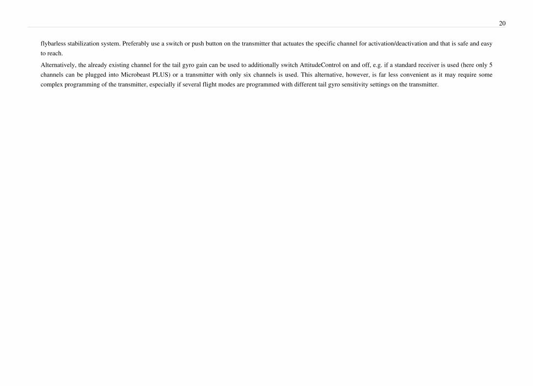
To teach the failsafe position simply set the throttle channel on your remote control to the desired position and press the button briefly. If you did not connect a function toCH5 Output and don't need throttle failsafe, press the button to complete setup anyway!
N - Throttle failsafe position 28
During failsafe setting the CH5 Output is enabled and can be controlled by the transmitter channel that is assigned to throttle function. This allows to check your throttleposition in reality. When using electric models make sure the motor is disconnected from the ESC or the pinion is removed from the motor, so that it will not drive the modelby accident.
This completes the receiver setup and the MICROBEAST PLUS will go into sleep state after the button is pressed (all Menu-LEDs flash). Power off the unit and power itagain. It will start with the standard initialization procedure and if the adjustments of Receiver setup menu have been set correctly, the unit will recognize your receiver andcontrol channels now. You can see this by the circulating LED row on the right side (Menu-LEDs H-N). When the receiver initialization is finished the row will disappearand change to circulation of Menu-LEDs A-G that shows sensor initialization is running. If this is finished too, MICROBEAST PLUS will go into operation mode and youmay proceed with basic setup of your helicopter.
29
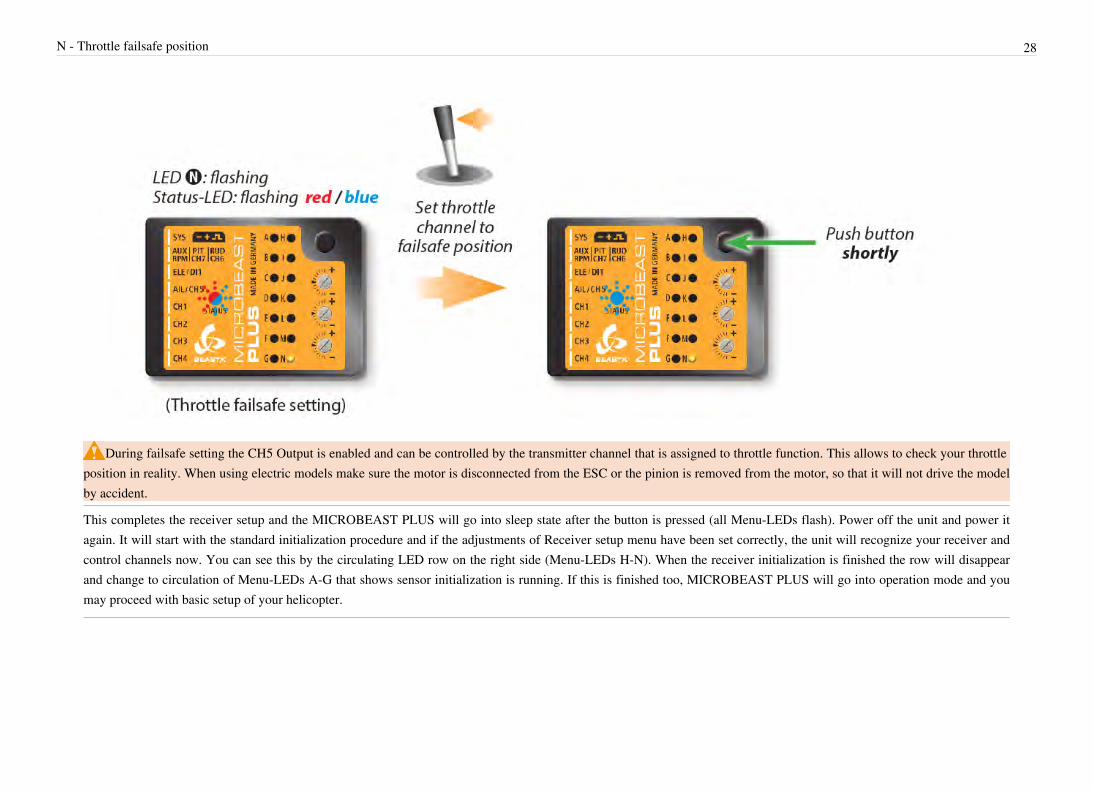
Setup menuBefore the first flight MICROBEAST PLUS has to be adjusted to your helicopter mechanics and its components. This is done in Setup menu level.When MICROBEAST PLUS shows that the system is ready, press and hold the button down. The Menu-LED next to menu point A will begin to flash and then after awhile will be steady on. Now and only now you can release the button. You just entered the Setup menu at menu point A.
Proceed step by step through the different menu points and perform the basic adjustment as described on the specific pages. By briefly pushing the button at each step youwill save the current setting and proceed to the next step. To leave the Setup menu you have to go through all menu points. After pushing the button at the last menu point(depending on installed firmware features and selected receiver type this either can be Setup menu point M or N or Governor menu point F or H) you will exit the Setupmenu and the system is ready for operation again. Then again none of the LEDs A - N are glowing anymore.

30
If you need to change some specific setting later onwards you can enter the Setup menu again and skip the other menu points by only pressing the button without changinganything at these points. So you can navigate to the desired menu point by simply pressing the button several times untli you reach this point. Then after you have finishedthe adjustment, again press the button repeatedly to proceed to the end of the menu and to get back into operation mode.
Never fly while MICROBEAST PLUS is in Setup menu! In this condition the gyro control and the stick controls are disabled.If there is no stick or button input for 4 minutes while being in the Setup menu, MICROBEAST PLUS will exit the menu automatically. However, this will not happen
at Setup menu points D, G, I and J to give you enough time to adjust the mechanical setup of your helicopter at these points.
A - Mounting orientation 31
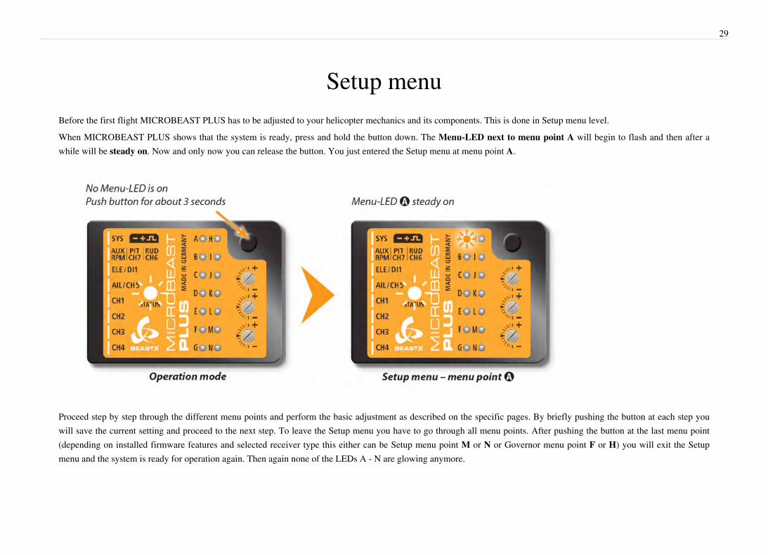
A - Mounting orientationThe MICROBEAST PLUS unit can be mounted in nearly all possible orientations. The only restriction is that the plug connectors have to point in or against flying directionand the egdes of the unit must be parallel to the rotation axis.At Setup menu point A choose the orientation that the unit is actually mounted on your heli. There are 8 possible orientations. The color of the Status-LED displays thecurrently selected orientation:
Status-LED Mounting orientation
off flat, sticker on top side, socket points in flight direction
purple flashing flat, sticker on top side, socket points in flight direction
purple flat inverted, sticker on bottom side, socket points in flight direction
red flashing vertical inverted, button is on the bottom, socket points in flight direction
red flat, sticker on top side, socket points to the tail boom
blue flashing vertical, button is on the top, socket points to the tail boom
blue flat inverted, sticker on bottom side, socket points to the tail boom
red/blue vertical inverted, button is on the bottom, socket points to the tail boom
You can switch between the options by briefly moving the rudder stick to one or the other direction. The Status-LED will change the color accordingly.
When finished briefly push the button to save the configuration and to proceed to Setup menu point B.

B - Swashplate update rate 32
B - Swashplate update rateSetup menu point B is for selecting the servo frequency (pulse rate) of your swashplate servos. To optimize the performance of MICROBEAST PLUS, the rule is the higherthe better! Nevertheless if you experience an unusually high power consumption of the receiver power supply or if the servos get hot, you should reduce this frequency.When using a servo that allows a higher frequency as MICROBEAST PLUS offers or that allows a maximum frequency which is not choosable, please select the next lowerfrequency that is closest to the given frequency. Using a lower frequency is always possible. Only too high frequencies can damage the servo and/or will cause the servo tonot work properly. Here you can find a list of parameters for the most common servos. Please understand that we can not list all servo types. We also can not guarantee theaccuracy of this data. Ask the manufacturer of the servos or your local dealer for detailed information.
If you do not know what the maximum pulse rate tolerated by your servos is, do not select more than 50Hz driving frequency. A higher driving frequency canlead to failure of the servos!With high frequencies, some servos run in a jerky manner, especially the fast ones with coreless or brushless servos. This is due to the high update rate that the servoreceives. This is not critical and will not impact flight performance.
To select the desired servo frequency, move the rudder stick repeatedly in one direction until the Status-LED lights in the correct color:
Status-LED Swashplate servo frequency
purple 50 Hz
red flashing 65 Hz
red 120 Hz
blue flashing 165 Hz
blue 200 Hz
off user defined
The option “user defined” allows you to choose your own setting that can be edited by using the StudioX software bundle and the separately available USB2SYS interface.Now plug in the swashplate servos, but do not install the servo horns yet as the servos could bind and get damaged on first power up:

B - Swashplate update rate 33
In slot CH1 is the elevator servo. With electronic swashplate mixing the two aileron servos have to be connected to CH2 and CH3 (the left/right ordering does not matter).With a mechanical mixed head (H1) the aileron servo connects to CH2 and collective pitch servo to CH3.

B - Swashplate update rate 34
When you route the wire leads in your model make sure that there is no tension passed to the MICROBEAST PLUS. Make sure that MICROBEAST PLUS is able to movefreely, so no vibrations get passed onto the unit by the wire leads. It is not recommended to bundle or tie down the leads close to the MICROBEAST PLUS. On the otherhand the wires must be attached so that they are unable to move the MICROBEAST PLUS during the flight caused by g-force. In particular, do not use any shrink tubing orfabric hose to bundle or encase the wiring in close proximity to the point at which the cables are plugged into the MICROBEAST PLUS. This makes the cables stiff andinflexible and can cause vibrations being transmitted to MICROBEAST PLUS.
Push the button to save the configuration and to proceed to Setup menu point C.
C - Tail servo center pulseAt Setup menu point C you can select the pulse length for the rudder servo‘s center position. Almost all commercially available servos work with 1500 - 1520 μs. But thereare a few special rudder servos on the market which use a different center position pulse length.

C - Tail servo center pulse 35
Here you can find a list of parameters for the most common servos. Please understand that we can not list all servo types. If a servo needs a special pulse length this usually ismentioned in the data sheet of the servo, mentioned on the packaging or directly printed on the servo. Ask the manufacturer of the servos or your local dealer for detailedinformation. If in doubt about the center pulse for your servo use the setting 1520 μs. It is very likely that the servo will work with this pulse length. Also when the servo israted with 1500 μs center pulse use this setting. There is barely any difference between 1500 and 1520 μs and the operating pulse range is nearly the same, so these servos areall of the same type.
There is a relationship between the setting of the rudder servo center pulse length and the rudder servo frequency (Setup menu point D). If a pulse length is selected that doesnot allow a certain frequency, the frequency is automatically reduced. The center position pulse setting always has priority, since a servo can run without problems at a lowerfrequency but can not be operated with an incorrect center position pulse.
To select the desired servo center pulse repeatedly move the rudder stick in one direction until the Status-LED glows in the correct color.

C - Tail servo center pulse 36
Status-LED Rudder servo center pulse length
purple 960
red 760
blue 1520
off User defined
The option “user defined” allows you to choose your own setting that can be edited by using the StudioX software bundle and the separately available USB2SYS interface.
Push the button to save the configuration and to proceed to Setup menu point D.
D - Tail servo update rateAs with the swashplate servos at Setup menu point B you can select at Setup menu point D the update frequency for the rudder servo. For best tail gyro performance, the ruleis the higher the better! A good rudder servo should be capable of running at least 270Hz. Nevertheless if you experience an unusually high power consumption of thereceiver power supply or if the servo gets hot, you should reduce this frequency. When using a servo that allows a higher frequency as MICROBEAST PLUS offers or thatallows a maximum frequency which is not choosable, please select the next lower frequency that is closest to the given frequency. Using a lower frequency is alwayspossible. Only too high frequencies can damage the servo and/or will cause the servo to not work properly. Here you can find a list of parameters for the most commonservos. Please understand that we can not list all servo types. We also can not guarantee the accuracy of this data. Ask the manufacturer of the servos or your local dealer fordetailed information.
If you do not know what the maximum pulse rate tolerated by your servos is, do not select more than 50Hz driving frequency. A higher driving frequency canlead to failure of the servos!Please note that depending on the rudder servo center position pulse length chosen at Setup menu point C, you may not be able to choose a frequency higher than 333Hz.This also applies to the “user defined“ setting which might be limited to 333Hz (Setup menu point C).
To select the desired servo frequency, move the rudder stick repeatedly in one direction until the Status-LED lights in the correct color:

D - Tail servo update rate 37
Status-LED Rudder servo frequency
purple 50 Hz
red flashing 165 Hz
red 270 Hz
blue flashing 333 Hz
blue 560 Hz
off user defined
The option “user defined” allows you to choose your own setting that can be edited by using the StudioX software bundle and the separately available USB2SYS interface.Now connect the rudder servo to [CH4] port of MICROBEAST PLUS:

D - Tail servo update rate 38
Attach a servo horn to the rudder servo in such a way that the tail linkage rod forms a 90 degree angle to the servo horn (or as close as possible). Then adjust the linkage rodas described in the manual for your helicopter. For most helicopters the tail pitch slider should be centred and the tail rotor blades will then have some positive pitch tocompensate for the torque of the main rotor. This mechanical adjustment especially is important when using the tail gyro in Normal-Rate mode. If the adjustment was notdone properly the helicopter will constantly drift to one side or the other on the rudder axis. When using the tail gyro only in HeadingLock mode this adjustment is not socritical. Here the gyro will actively control the rudder so the helicopter does exactly follow the commands of the rudder stick. For optimum performance it is neverthelessrecommended to perform the mechanical adjustment as good as possible.Note: This menu item will not be left automatically after 4 minutes, so you have plenty of time to adjust the mechanical setup!
Push the button to save the configuration and to proceed to Setup menu point E.

E - Tail servo limits 39
E - Tail servo limitsAt Setup menu point E you adjust the best possible servo throw for your tail rotor. The optimum throw is determined by the maximum possible control travel of the tailmechanism or based on the maximum allowed angle of attack of the tail rotor blades that will not lead to an aerodynamic stall of the blades. Such stalls can cause very badstopping behavior like overshooting of the tail when stopping from rotation and can also cause bad tail response to rudder stick input when performing directional changes.Keep this in mind when adjusting the tail rotor endpoints. Several helicopters on the market allow for a very wide range of tail travel. Here is not necessarily useful to use thewhole range of travel. Check the helicopter‘s manual to find out where to set tail pitch end points.To adjust the limits, move the rudder stick in one direction until the servo reaches the maximum endpoint without any binding or stall and release the rudder stick. Thefurther you move the rudder stick the quicker the servo will steer into the given direction. If you move the servo too far you can steer the stick to the opposite direction andmove the pitch slider a short way back. Once you adjusted the maximum endpoint don‘t move the rudder stick anymore and wait for the Status-LED to flash and light steadyred or blue, depending on the adjusted direction. Now you have saved the servo limit for one direction.

E - Tail servo limits 40
Then adjust the servo limit for the other direction. Drive the tail pitch slider by using the rudder stick to the other maximum endpoint and then release the rudder stick. Aftera short moment, the color of the Status-LED should start flashing followed by lightning steady purple (mix of red and blue) indicating that the servo endpoint adjustment iscomplete.
Pay attention that the steered direction of your rudder stick corresponds to the direction your helicopter should turn. If this is not the case, use your transmitter‘s servoreversing function for the rudder stick. If you‘re not sure in which direction the helicopter should rotate consult the manual for your helicopter.
If the Status-LED does not light or lights in an unexpected color, the servo throw is obviously too small. In this case mount the linkage ball of the tail linkage rod furtherinward on the servo horn. This ensures that the tail gyro of MICROBEAST PLUS will perform in the best way and that enough servo resolution is available.
By (re-)adjusting tail rotor endpoints the servo center trim will be reset to zero (in case it has been changed at Parameter menu point A).

E - Tail servo limits 41
Push the button to save the configuration and to proceed to Setup menu point F.
F - Tail gyro directionAt Setup menu point F you you have to check if the tail gyro of MICROBEAST PLUS does compensate to the correct direction.
The gyro always tries to steer in the opposite direction of the rotation that is applied to the helicopter. If you move the helicopter by hand around its vertical axis, the gyromust actuate a rudder servo movement to compensate this rotation. If for example you move the nose of the helicopter to the left (tail moving to the right), the gyro has tosteer right the same way as you would steer right with the rudder stick, so that the tail is pushed back to the left.
When moving the tail to the right byhand (nose of the heli to the left), the
gyro will steer to the right, so the tail ispushed back to the left.
When moving the tail to the right byhand (nose of the heli to the left), the
gyro steers to the left and so will movethe tail even further.
If the gyro does not move the tail rotor to the correct direction you have to reverse the gyro direction. This happens by moving the rudder stick once into any direction. Forconfirmation you will see that the Status-LED will change its color:

F - Tail gyro direction 42
Status-LED Tail gyro direction
red normal
blue reversed
Once again repeat the test as described above. MICROBEAST PLUS should now correct in the right way. Check this function painstakingly as wrong gyro direction willcause the helicopter to spin at very high speed on the vertical axis when trying to takeoff!
Push the button to save the configuration and to proceed to Setup menu point G.
G - Swashplate servo trimWhen entering Setup menu point G connect all swashplate servos as described in chapter 3.3. They now will be running to their origin zero position (1520 µs) what we callreference position here when the Status-LED is off. This reference position is used to mount the servo horns on the servos at their true center position, so that you get roughlyequal throws to both direction. Mount the servo horns so that they form as much as possible a 90 degrees angle to the linkage rod. Then in the next step you electronicallyfine trim every single servo‘s center position, as usually mounting the servo horn at exact 90 degrees will not work out perfectly depending on the servo‘s gear train and theservo horn.Note: Although if you were able to mount the servo horn perfectly at 90 degrees, check the electronical trimming as described below as the reference possition is not usedlater onwards and in operation but the trimmed position is!If you move the rudder stick to a single direction once, you can select one servo and change its center position by moving the elevator stick back and forth. Every color of theStatus-LED is corresponding to a specific servo channel that is indicating its selection by a short up and down move. If you move the rudder stick once again in the samedirection as before, you can select the next swash servo and adjust its center position by using the elevator stick. You can switch back and forth between the servos as oftenas you need and also switch back to the reference position anytime. The already adjusted servo centers will not be lost by doing this.

G - Swashplate servo trim 43
Status-LED Swashplate servo center trim
off Swashplate servos at reference position
purple CH 1 – elevator servo center trim adjust
red CH 2 – aileron(1) servo center trim adjust
blue CH 3 – aileron(2)/pitch servo center trim adjus
Only the trimmed servo positions are important and get stored (those which have been set with the corresponding Status-LED colors). The servo positions at Status-LED offonly serve for reference and to get the servo horns best plugged into position, for instance if you install new servos or replace the servo gears after a crash. This referenceposition will not be used later onwards. Only the servo positions with active trimming are important.
Now if servos are trimmed do not yet proceed to the next menu point. With active trimming (Status-LED still lights up in one color!) adjust the linkage rods accordingto your helicopter manual. The swashplate should now be at the midpoint and perpendicular to the main shaft and the rotor blades should have 0 degrees of pitch. Alwayswork this out from bottom (servos) to top (blade grips). Also don‘t forget to level and phase the swashplate driver in the correct way (if it‘s adjustable)! At 0 degrees of pitchthe swash driver arms must be horizontal and the linkage balls of the blade grips have to be perpendicular to the spindle shaft.

G - Swashplate servo trim 44

G - Swashplate servo trim 45
Push the button to save the configuration and to proceed to Setup menu point H.

H - Swashplate mixing type 46
H - Swashplate mixing typeAt Setup menu point H you can choose the electronic swashplate mixer your helicopter requires or choose “mechanical“ for switching of the electronic swashplate mixer ifyour helicopter has a mechanical mixer. For the electronic mixer by default MICROBEAST PLUS supports 90°, 120° and 140° swashplates. Besides these choices, you canset any swashplate geometry by using the StudioX software bundle in combination with the optional USB2SYS interface. This also includes setting a virtual swash phasingfor scale helicopters. Which kind of CCPM your helicopter uses can be read in the manual for your helicopter.
If your helicopter requires an electronic swashplate mixer by no means use your transmitter‘s swashplate mixer function!The mixing is all done by MICROBEAST PLUS. Deactivate the swashplate mixing in your transmitter or program it to mechanical mixing (which is often called “normal“,“H1“ or ”1 servo“ mixing), even if your helicopter requires electronic mixing. Also see the section about preparing the transmitter.
The color and state of the Status-LED shows the currently selected mixing type. To select the desired type, move the rudder stick repeatedly in one direction until theStatus-LED lights in the correct color:
Status-LED Swashplate mixer
purple mechanical
red flashing 90°
red 120°
blue flashing 140°
blue 140° (1:1)
off user defined

H - Swashplate mixing type 47
The type 140° (1:1) is the most common type of "140° degrees" swashplates. Often it is also considered as 135° swashplate! There is no uniform designation for this type ofswash mixing. The main idea with this type of swash is to have an equal servo ratio on the elevator axis. If this is the case on your helicopter (elevator and aileron servos aremoving the same distance when steering elevator) then choose this type, no matter whether it‘s called 135° or 140° swashplate. You can find this type of swashplate forexample on Shape, JR and Hirobo helicopters.
Push the button to save the configuration and to proceed to Setup menu point I.

I - Swashplate servo directions 48
I - Swashplate servo directionsAt Setup menu point I, you adjust the correct swashplate servo directions. To facilitate this setup, you don’t need to adjust every servo by its own, but just try the 4 possiblecombinations. Move the thrust stick and check if the swashplate moves horizontally up and down. The direction itself is not yet important. If one or more servos are notrunning in the right direction, just choose another combination of servo directions by giving a short rudder input. Repeat this rudder input until all servos are running in thesame direction and moving collective pitch up and down.
Status-LED Servo directionsCH1 - CH2 - CH3
off normal - reverse - reverse
purple normal - normal - reverse
red normal - reverse - normal
blue normal - normal - normal
If the servos are not reacting properly to aileron and elevator functions, check if the servos and receiver wires are connected as described above. Also check if thechannel assignment within Receiver menu has been done correctly if applicable. Additionally verify the settings of your transmitter on any remaining mixer functions andcheck if the transmitter is set to the correct stick mode (see the section about preparing the transmitter).
Check now, if your control directions of aileron, elevator and collective pitch are correct.If this is not the case, you have to use the servo reverse feature of your transmitter to reverse the appropriate control function. Do not change the servo directions ofMICROBEAST PLUS anymore! When the servos drive the swashplate up and down when giving collective pitch input, then the servo directions are setup correctly. Thecontrol directions are only a matter of stick input coming from the transmitter.Note: This menu item will not be left automatically after 4 minutes, so you have plenty of time to adjust the mechanical setup.
Push the button to save the configuration and to proceed to Setup menu point J.

J - Swashplate servo throw 49
J - Swashplate servo throwAt Setup menu point J you have to teach MICROBEAST PLUS the cyclic pitch ratio. First don‘t touch any stick on your transmitter when entering Setup menu point J.Orientate the rotor blades (or one of the rotor blades when using a rotorhead with more than two blades) so that they are parallel to the tail boom. The swashplate should be inthe neutral position and the blades should have 0 degrees of pitch (if this is not the case repeat the swashplate servo centering at Setup menu point G). Then attach a pitchgauge to one of the rotor blades on the longitudinal axis to measure aileron pitch from the front or from behind the heli.

J - Swashplate servo throw 50
Move and hold the aileron stick to one direction until the rotor blade has an exact 6 degrees of cyclic pitch, then release the stick. If you moved the swashplate too far youcan steer the stick to the opposite direction and reduce the pitch. The direction you choose is not important, what is important is that you keep the position steady on 6° whenyou save and leave this menu point. Do not go to 6° and then move back before saving and leaving.

J - Swashplate servo throw 51
When reaching 6 degrees, the Status-LED should light blue. This indicates that your helicopter‘s rotor head geometry is perfect for the use with a flybarless system.Otherwise, if the Status-LED‘s color is red or purple or even if the Status-LED is off, this indicates that your helicopter‘s geometry is not optimal for flybarless usage. Correctthis by using shorter servo horns, shorter linkage balls on the inner swashplate ring or longer blade grip link levers.
Always set the cyclic pitch to 6 degrees! This setup does not affect the maximum rotation rate of the helicopter but is only there to show and teach MICROBEASTPLUS the actual mechanical cyclic geometry and to estimate servo throws. A wrong adjustment at this step may be extremely detrimental to the performance ofMICROBEAST PLUS. The blue color of the Status-LED is secondary and just for information. Do not try to get a blue Status-LED by any means. For example if the LEDonly lights up red when the pitch is set to 6° then use this adjustment anyway but keep in mind that your helicopter‘s head geometry is not perfect. Do not adjust 7° forinstance just because the Status-LED does become blue there!
By moving the rudder stick to one direction you can also delete the adjustment and reset the swashplate back to 0 degrees, e.g. to readjust your pitch gauge.Note: This menu item will not be left automatically after 4 minutes, so you have plenty of time to adjust the mechanical setup.

J - Swashplate servo throw 52
Push the button to save the configuration and to proceed to Setup menu point K.
K - Swashplate pitch adjustmentAt Setup menu point K you adjust the maximum desired negative and positive collective pitch. Move the thrust stick all the way up and let it stay there. Now you canincrease or decrease the maximum amount of collective pitch using the aileron stick. When you adjusted the desired maximum pitch angle, move the thrust stick all the waydown and again increase or decrease the collective pitch to the minimum desired value using the aileron stick.
Don‘t use any pitch curves in your transmitter while doing these adjustments. Later on for the flights, you can adjust your pitch curves as you like and are used to. Setupmenu point K solely serves to teach MICROBEAST PLUS the maximum pitch range and the endpoints of the thrust stick.
At this point, verify again that the demanded collective pitch direction on the transmitter is in the correct direction for the model. Otherwise use your transmitter‘s servoreversing function for the collective pitch channel to correct this as already described in the section about Setup menu point I.
Now check the internal collective pitch direction of MICROBEAST PLUS:The current pitch direction is indicated by the color of the Status-LED. When the thrust stick is set to positive collective pitch, the Status-LED must light up in blue color,when the stick is set to negative pitch the Status-LED must light in red. The crucial factor is the actual pitch angle of the rotor blades, not the position of the thrust stick! Ifthe display of colors is inversed, i.e. the Status-LED lights blue when pitch is negative and lights red if pitch is positive, the directions can be interchanged by moving therudder stick once into any direction. Check this setting several times and very conscientious. The setting is very important for proper function of AttitudeControl (if you donot use this feature by now you should check and set the pitch direction anyway).
Push the button to save the configuration and to proceed to Setup menu point L.

L - Swashplate cyclic limit 53
L - Swashplate cyclic limitAt Setup menu point L you adjust the maximum possible tilting of the swashplate for aileron and elevator. The deflection will be limited in a circular path similar to a cyclicring function.For adjustment proceed in the following way:Carefully move the sticks for aileron, elevator and pitch to all maximum end points and watch out if the swashplate, the linkage rods or servos are binding somewhere oreven getting not more driven.By moving the rudder stick to the left or right, you can increase or decrease the throw limiter. The limiter affects all servo directions, so adjust it until there is just no bindingat all possible servo deflections. Always try to achieve the maximum possible cyclic throw. This will ensure that the maximum possible rotation rate of the helicopter can beachieved and the the gyro control loop does not get sacrificed.
Similar to Setup point J, the color of the Status-LED indicates whether the adjusted limit allows sufficient cyclic throw. In the ideal case, the swashplate is limited onlyto the extent where the Status-LED still lights blue. In particular, for models that are intended to be used in 3D aerobatics, 10° to 12° cyclic throw should be possible. Buteven for all the other helicopters, it is recommended to adjust as much throw as possible, because otherwise the control loop may not work properly. Here, the color of theStatus-LED provides a clue. If you get only purple or even no light at all, it is essential that you change the mechanical setting of your model to increase the available throw.
If afterwards any modifications are done to one of the other Setup menu points which affect servo adjustments (Setup menu points G, J and K) the cyclic swashplatelimit adjustment has to be checked and redone.
Push the button to save the configuration and to proceed to Setup menu point M.

M - Swashplate gyro directions 54
M - Swashplate gyro directionsAt Setup menu point M you check if the sensors for aileron and elevator are measuring the correct direction. This can be directly verified in this menu point when you roll ortilt the helicopter by hand. The swashplate has to steer against the rotational movement:
When tilting the helicopter forward the swashplate has to move backwards, when tilting the helicopter to the back, the swashplate has to compensate forward. Samething applies to the roll axis: when you roll the helicopter to the left the swashplate has to steer right and vice versa. Basically the swashplate has to remain horizontal all thetime while banking the helicopter.
If this is not correct, you can reverse the gyro directions by moving the rudder stick into one direction. For confirmation you will see that the Status-LED changes color.Repeat reversing directions step by step until the correction on both axis is working as expected. There are four possible displays to choose from, one of them will give thecorrect swash movement:

M - Swashplate gyro directions 55
Status-LED Swash gyrocompensation
(Elevator - Aileron)
off reversed - reversed
purple reversed - normal
red normal - reversed
blue normal - normal
Once again repeat the test as described above. MICROBEAST PLUS should now correct in the right way. Check this function painstakingly as wrong gyro compensationwill cause the helicopter to tip over and crash when trying to takeoff!Note: The sensor direction colors may differ between different BEASTX devices and different MICROBEAST/MICROBEAST PLUS firmware versions. Therefore theStatus-LED colors should be used as reference for one device with one specific firmware version only. We highly recommend not to rely on the Status-LED color whentransfering setups from one device to another. Always check sensor directions manually!
When the RPM Governor feature is installed on your unit and you're using a single-line receiver, push the button to save the configuration and to proceed to Setup menupoint N. Otherwise pushing the button will end the Setup menu adjustment and you will get back into operation mode.

N - RPM Governor mode 56
N - RPM Governor modeThis menu point is only accessible if you have installed the RPM Governor feature on your device and in case you're using a single-line receiver. The RPMGovernor function is not applicable when a Standard receiver is used!
At Setup menu point N you can choose between three different options:• no governor - the RPM Governor is not used. All control commands on the throttle channel will be passed to [CH5] output directly.• electric governor - select this option if your helicopter is powered by an electric motor and an electric speed controller is plugged into [CH5] output of MICROBEAST
PLUS. MICROBEAST PLUS reads the rpm signal from the speed controller or a phase sensor and controls the rotor speed accordingly. Note that the controller itself mustnot be operated in a (heli specific) governor mode. The speed controller must process the incomming throttle signals and control the motor as direct and unfiltered aspossible.
• nitro governor - with this option MICROBEAST PLUS can govern the rotor rpm of a helicopter with nitro or gas engine. For this MICROBEAST PLUS controls thethrottle servo which is connected to [CH5] output and that controls the carburetor of the engine. The motor rpm will be read from a magnetic or optical sensor thatcaptures the rpm from the crankshaft of the motor, the clutch bell or the main gear.
The choice is done by moving the rudder stick in one direction until the LED indicates the desired color and state.
Status-LED Governor mode
off no governor
red electric
blue nitro
If the RPM Governor is deactivated (option no governor) MICROBEAST PLUS will exit the Setup menu if you briefly press the button. Otherwise pressing the button willlead to Governor menu point A (after Menu LED N now Menu LED A will flash)!

57
Parameter menuThe Parameter menu offers a variety of settings with which you can further improve the system performance and which allow you to adjust the flight characteristics of thehelicopter to suit your personal preferences. Normally for the first flight you don‘t need to make any adjustments here. Only the control behavior (menu point B) and the stickdeadband (menu point E) should be adapted under certain circumstances.When MICROBEAST PLUS is ready for operation, hold down the button until the Menu-LED next to point A flashes quickly and release the button immediately. Theflashing menu LED A shows that you've entered Parameter menu point A. Do not hold the button too long, as this will enter Setup menu!
To switch to the next Parameter menu point, just briefly press the button once again. After the last menu point (depending on the installed feature set this can be menu pointH, K or M) pressing the button one more time exits the Parameter menu and MICROBEAST PLUS is ready for operation again (in this case the Status-LED will indicate thetail gyro mode and the LEDs A - N are off).

58
Single menu points can be skipped without performing any changes. Therefor don‘t move any stick while you are at the menu point you want to skip and just press the button(repeatedly) again, until you reach the menu point you want to adjust. Then again skip the following menu points (if there are any) by pressing the button, until the parametermenu level will be exited.
Never fly while MICROBEAST PLUS is in Parameter menu! In this condition the gyro control and the stick controls are disabled.If there is no stick or button input for 4 minutes, while being in the Parameter menu, MICROBEAST PLUS will exit the menu automatically.

A - Quick trim 59
A - Quick trimThe first menu point of the Parameter menu gives you the possibility to easily adjust your servo center trim on the flying field as for instance your helicopter does slowly driftin hovering flight or when it doesn’t climb out straight on collective pitch inputs. Additionaly when using the AttitudeControl feature you may trim the reference point for theartificial horizon in case the heli is not leveled correctly.
Never use the trim functions of your remote control! MICROBEAST PLUS will see trim as a control command to turn the heli and not as servo trim.There is one exception: The rudder servo can be trimmed on the remote control when the tail gyro is operated in Normal-Rate mode. Note, however, that this trimmingshould only be temporary as MICROBEAST PLUS calibrates the stick center positions during every initialization process. Thus, on the next flight the servo would be backon center position despite trimming in the transmitter.
Swashplate servosContrary to centering every single servo at Setup menu point G, here you are able to directly adjust aileron and elevator without taking care about the single servos. Similarto the digital trim function of most transmitters here at Parameter menu point A you can adjust the swashplate “one click“ by shortly moving the aileron or elevator stick inthe desired direction. If you want to trim the swashplate any further repeat tapping the stick several times or simply hold the control stick pushed for a longer time toautomatically perform several trim steps. The color of the Status-LED gives you an approximate indication of how much you did trim.Please note that this function, as opposed to the digital trim of the transmitter, is not a separate trim function. Here you directly adjust the servo centers as well as you wouldset servo centers at Setup menu point G. Technically there is no difference between Parameter menu point A and Setup menu point G.
Rudder servoIf the tail gyro is operated in Normal-Rate mode, the rudder servo must often be trimmed precisely so that the tail rotor produces just enough thrust to counteract the rotortorque in hovering flight. Otherwise the helicopter would constantly drift into one or another direction on its vertical axis as the gyro only dampens sudden movements butdoes not control the tail rotor‘s absolute position.To trim the rudder servo proceed as follows: Switch the tail gyro to Normal-Rate mode fly the helicopter. By using the digital trim function of your transmitter trim therudder servo so that the helicopter does not drift in hovering flight. Land the helicopter and immediately open Parameter menu point A by briefly pressing the button onMICROBEAST PLUS once. To take the tail trim value from the transmitter once again press the button and this time hold it for at least 2 seconds (if you briefly press thebutton only, you would switch to menu point B!). You can see the rudder servo move to the new center position and the Status-LED will flash for some moment to signalizethe position has been set. Now reset the digital trim of your transmitter back to zero.
A - Quick trim 60
•• MICROBEAST PLUS only accepts the the tail trim value from the transmitter when the gyro is set to Normal-Rate mode. When you land after the trim flight and openParameter menu point A make sure that you do not change the gyro mode and/or trimming of the transmitter by accident, e.g. when using a flight mode switch in thetransmitter.
•• If the tail gyro solely is operated in HeadingLock mode, trimming the rudder servo is not required under normal circumstances. Here the gyro actively controls the rate ofrotation whereby drifting is excluded on the vertical axis. Anyhow, in unfavorable mechanical conditions it may be helpful to fly the heli in Normal-Rate mode once andto trim the rudder servo accordingly, so that the mechanical throw is balanced more equally.
Reset adjustmentDuring the trim procedure you can delete the just performed trimming by moving the rudder stick in any direction. All servos will be moved to the initial position fromentering Parameter menu point A. Note that a subsequent reset to previous states is not possible! If the servo trimming was changed and Parameter menu point A is left, theservo positions will be saved permanently. You can only bring back the servos to the previos positions by manually trimming them back into the opposite direction.
The trimming of the rudder servo will be fully deleted when the tail rotor endpoints are readjusted at Setup menu point E!
Trimming the artificial horizon (optional)If the helicopter is not aligned horizontally as desired with active AttitudeControl, i.e drifts to one side in hovering, the artificial horizon can be readjusted. To do so, activate AttitudeControl at Parameter menu point A via the transmitter‘s AttitudeControl channel to switch from trimming of the servos to trimming of the horizon. The Status-LED will flash indicating that AttitudeControl is on (if the Status-LED is lit permanently, you are in servo trimm mode as described above). By moving the aileron or elevator stick the roll and pitch tilt of the horizon can be increased/decreased. Briefly touching the appropriate stick will trim the horizon stepwise by 0.5 degrees to the specific direction. Touching the stick repeatedly or holding it for longer time will trim the horizon by several steps. The Status-LED indicates the trim values: when it lights in blue color both angles are 0 degrees resp. they are in the factory setting. If the Status-LED lights red, one or both angles are adjusted slightly. If the Status-LED is purple then one axis is trimmed by more than 5.0 degrees. When the Status LED goes out, one of the two axes is further trimmed than 10.0 degrees, which is the limit for each axis! By moving the rudder stick you can remove the trimm that has been set since entering this menu point. Place the helicopter in horizontal position and you should be able to see the effect of trimming. Note that the helicopter usually is slightly tilted to the side in hovering flight due to the drag of the tail rotor. Therefore as a starting point you may trim about 1-2 degrees to the right when using a helicopter with clockwise turning main rotor to make the heli tilt against the rotor torque, but by default it should not be necessary to use any trimming at all. Note that AttitudeControl can not recognize the absolute position of the helicopter. Depending on wind and environmental conditions it may happen that the helicopter drifts slightly into a certain direction during hovering flight. Also long-lasting vibration or fluctuations in temperature can cause the helicopter not always comply exactly the same attitude. Also make sure the MICROBEAST PLUS unit is perfectly aligned to the rotation axis of the helicopter otherwise you the axis will be cross connected together and the calculation of the artificial horizon will not match the real movement of the heli. Therefore only trim in moderate steps and only when the helicopter reproducible drifts to the same direction otherwise trimming can make the drift

A - Quick trim 61
even worse!
Push the button to save the configuration and to proceed to Parameter menu point B.
B - Control styleAt Parameter menu point B you can choose between different control behaviors/control styles for your helicopter. This includes the maximum rotation rate of the helicopteras well as how sensitive MICROBEAST PLUS will react to stick inputs for aileron, elevator and rudder around the stick centre (Stick expo).Factory setting for this option is “sport“! This should be suitable for most pilots. If you are a rather inexperienced model pilot it is absolutely suggested to select the option„normal” for the first flights. Here the rotation rate on cyclic and rudder is highly decreased and the stick inputs around center are very gentle.To find your individual preference increase the option step by step. The choice is done by moving the rudder stick in one direction until the LED indicates the desired colorand state.
Status-LED Control behavior
purple normal
red flashing sport
red pro
blue flashing extreme
blue transmitter
off user defined
If you are not satisfied with the presets, you may adjust the control behavior by using your remote control. To do so, set the control behavior to “transmitter” (Status-LED“blue“). Then the maximum rotation rate for aileron, elevator and rudder can be adjusted by increasing or decreasing the servo travel for the corresponding function in yourtransmitter or by using the “DualRate“ function. 100% stick throw (servo throw) in the transmitter are equivalent to a rotation rate of apprx. 400deg/s on cyclics and 600deg/son rudder in this mode. To adjust the sensitivity around mid stick position you can use the “Expo“ function of your transmitter. Please refer to the manual for your transmitter.The option “user defined” allows you select your own predefined setting. This can be edited by using the StudioX software bundle in combination with the optionalUSB2SYS interface. Thus you can take the values of the predefined settings and modify them directly in the MICROBEAST PLUS software without the need of adjustinganything in the transmitter.

B - Control style 62
When using predefined control behaviors other than “transmitter“ we do not recommend to additionally adjust control curves (Expo/Dual rates) in your transmitter asthis will indefinably mix the preset curves of MICROBEAST PLUS with the curves of the transmitter! Anyhow, if you only make small adjustments (e.g. slightly increasingthe servo throw to increase rotation rate) this should be no problem.
If the tail gyro is operated in Normal-Rate mode the rudder stick directly controls the rudder servo instead of commanding a rotation rate to the gyro. In this mode theheli will turn as fast as it is determined by the rudder servo position and angle of attack of the rotor blades. The tail gyro does not monitor the rate of rotation. Therfore it ispossible when using Normal-Rate mode, that extremely high rotation rates can be achieved. It is absolutely necessary to check how much pitch angle can be achieved at fullrudder stick deflection at the tail rotor. Reduce the servo throw of the rudder servo by decreasing it on the remote control or limiting it at Setup menu point E to a reasonablelevel.
Push the button to save the configuration and to proceed to Parameter menu point C.
C - Speed flight stabilityWhile in fast forward flight apply jerky collective pitch inputs to test this parameter. The helicopter should mainly remain in its horizontal path during climbing anddescending. If the nose of the helicopter is pitching up and down heavily like a swimming dolphin, increase the value at Parameter menu point C to compensate for thiseffect. But if the value is too high, the helicopter might feel sluggish and lazy. Try to find the lowest suitable setting. Note that the Cyclic gain (Dial 1) must be set as high aspossible, otherwise the pitching up effect maybe a result of too low reaction of the gyro system in general.If the helicopter is still pitching up at the highest value, check if the swashplate has enough cyclic throw at high collective pitch values (Setup menu point L) and use fasterand stronger servos as well as rotor blades that are as neutral as possible (for example blades specifically designed for flybarless helis).The currently selected value is indicated by the Status-LED color and state. Move the rudder stick into one direction until the Status-LED lights in the desired color.
Status-LED Pitching up behavior
purple very low
red flashing low
red medium
blue flashing high
blue very high

C - Speed flight stability 63
off user defined
The option “user defined” allows you to choose your own setting that can be edited by using the StudioX software bundle and the separately available USB2SYS interface.
Push the button to save the configuration and to proceed to Parameter menu point D.
D - Rudder rate consistencyAt Parameter menu point D the HeadingLock gain for the tail can be adjusted. This gain comes into play when the tail gyro is operated in HeadingLock mode. It determineshow hard the tail gyro tries to maintain a given rotation rate from the transmitter. If the HeadingLock gain is too low, pirouettes will be inconsistent during fast forward flightor in crosswind conditions and the helicopter will slowly drift on the vertical axis when in stationary hovering flight with crosswinds. If the HeadingLock gain is too high, thetail rotor will respond delayed to fast directional changes and the rudder stick control does feel very inprecise. Also it is possible that the tail will bounce back slowly afterstopping from a rotation and commute gently while hovering or flying around. So only adjust this parameter as high as necessary.
Parameter menu point D only adjusts some part of the tail gyro control loop. First of all, you must adjust the tail gyro gain in the transmitter and use it to switch the gyro toHeadingLock mode.
•• Before adjusting the HeadingLock gain always try to find the maximum amount of tail gyro gain by flying around and using the tail gyro in HeadingLock mode.•• After adjusting the HeadingLock gain it might be necessary to readjust the tail gyro gain! Both parameters interact to each other.The currently selected value is indicated by the Status-LED color and state. Move the rudder stick into one direction until the Status-LED lights in the desired color.
Status-LED HeadingLock gain
purple very low
red flashing low
red medium
blue flashing high
blue very high
off user defined

D - Rudder rate consistency 64
The option “user defined” allows you to choose your own setting that can be edited by using the StudioX software bundle and the separately available USB2SYS interface.
Additional informationPlease note that poor tail performance very often may be a sign of a stiff tail mechanics, slop in the tail linkage or an inadequate rudder servo! The tail rotor system in thiscase does not react as precise as necessary and hinders the tail gyro from working properly. If you cannot increase the HeadingLock gain more than “very low“ or “low“without the tail rotor starting to slowly oscillate or bounce after doing a full stop, it is very likely that there is a mechanical issue. Also if on the other hand the tail does notturn constantly at high speeds or not turn around at all even in the setting „very high“, then again this may be due to a mechanical cause.Make sure that the maximum blade pitch at the tail rotor neither is too large nor too small. A large pitch angle can lead to a stall of the tail rotor blades. Then the tail rotorproduces hardly any thrust, similar to a very small angle. Also check the entire tail mechanics running smooth and without binding. Make sure that the rudder servo is strongenough and that it is supplied with sufficient power (long supply leads cause high voltage loss!). Check that the rudder servo does not get powerless at maximum servodeflection. This can happen if the pulse range of the servo is exceeded. The cause for lacking tail thrust also can be that the tail rotor blades are too small or too soft, orbecause the rotation speed of the tail rotor is too low!To gain better tail gyro performance also check for correct servo horn length. If the tail gain in general is very low and the rudder tends to oscillate very easy move thelinkage ball on the servo horn further inwards to the center. If on the other hand you have a very large amount of tail gain and the tail gyro still does not seem to be capable tohold the tail rotor in any flight condition, move the linkage ball on the servo horn further out from the center, to get faster response speed when the gyro needs to control therudder. Do not change the HeadingLock gain at menu point D in case the tail gyro does not hold well when abrupt direction changes occur as in general the HeadingLockgain does not compensate for quick changes.
Push the button to save the configuration and to proceed to Parameter menu point E.

E - Stick deadzone 65
E - Stick deadzoneUse Parameter menu point E to adjust the stick deadband for elevator, aileron and rudder sticks. The deadband is the range around the very center of the stick in whichMICROBEAST PLUS will not react to stick inputs.Unfortunately, some on the market available transmitters have the problem that when the sticks are brought back to the center position after a stick input, they aren’t exactlyat the same center position as before. This generates a continuous deviation on the corresponding function, although the stick seems to be at mid position. This deviation isinterpreted as a small input by MICROBEAST PLUS which leads to an unwanted drift on one or more axis. Especially you can see and feel this in hovering flight when thehelicopter is turning slightly to one or another direction all the time. This makes it difficult to have precise hovering as it is hard to find a stick position at which no input issent to MICROBEAST PLUS. This can be very dangerous as it may cause the helicopter to tip over when trying to take off or it can cause the pilot to loose control over thehelicopter at all! So increase the stick deadband stepwise just until you don‘t see such effects. Note that as a result of large stick deadband there will be a wide range aroundmid stick position in that MICROBEAST PLUS will not react to stick inputs. This will make the control more inprecise. So if using “large“ or “very large“ deadband isnecessary, we recommend to let your transmitter get checked by its manufacturer for damaged or worn out stick potentiometers.The choice is made by moving the rudder stick into one direction until the Status-LED lights in the desired color.
Status-LED Stick deadband
purple very small
red flashing small
red medium
blue flashing large
blue very large
off user defined
The option “user defined” allows you to choose your own setting that can be edited by using the StudioX software bundle and the separately available USB2SYS interface.
Push the button to save the configuration and to proceed to Parameter menu point F.

F - Torque precompensation 66
F - Torque precompensationThe advantage of always knowing the pitch and cyclic load on the flybarless system, allows MICROBEAST PLUS to precompensate for the torque variations on the tailrotor, just before any noticeable deviation occurs. This method of torque precompensation (RevoMix) relieves the tail control loop and improves the tail performance,especially when using MICROBEAST PLUS on helicopters with insufficient tail authority and/or extreme motor torque (e.g. well powered electric helicopters) where the taildoes blow out shortly when applying a sudden pitch or cyclic input.To see the compensation direction, you can move the collective pitch, aileron and elevator control stick at Parameter menu point F. With precompensation activated the tailrotor has to produce a deflection which must counteract the rotor torque. Since at 0° pitch the least torque is applied by the main rotor, also the tail rotor makes the leastdeflection and the tail slider is in center position. If you pitch in positive or negative direction or move aileron or elevator control, a deflection will be added to the tail rotorwhich will act against the torque of the main rotor.For helicopters with clockwise rotating main rotor, the precompensation has to always push the tail to the left (nose of the heli to the right). For helicopters with the mainrotor turning anti-clockwise, the precompensation has to push the tail to the right (nose of the heli to the left). The deflection will be to the same direction, whether positive ornegative pitch, as the torque only increases. So first of all check which direction is needed for your helicopter and determine the necessary Status-LED color (red or blue).Then you have two options to set the precompensation (low or high = Status LED flashing or constant lighting). The choice is made by moving the rudder stick into onedirection until the Status-LED lights in the desired color.
Status-LED Torque precompensation (RevoMix)
purple off
red flashing low - normal direction
red high - normal direction
blue flashing low - reverse direction
blue high - reverse direction
off user defined
Use torque precompensation when the tail does go away in torque direction when applying a sudden pitch input, even if the tail gyro gain is properly setup. Increase the amount of precompensation stepwise until the tail holds well. If the tail is moving against torque direction, the amount of precompensation is too high already. If the tail is blowing out even worse when torque precompensation is active, probably the direction of torque precompensation is wrong! If you can't find a good adjustment check the mechanical conditions. Use different (larger) tail rotor blades or higher tail rotor speed to gain better holding force. Also check your tail gyro gain. If the tail gyro gain in general is very low and the rudder tends to oscillate very easily move the linkage ball on the servo horn further inwards to the center. If on the other hand you have a very

F - Torque precompensation 67
large amount of tail gain and the tail gyro still does not seem to be capable to hold the tail rotor in any flight condition, move the linkage ball on the servo horn further outfrom the center, to get faster response speed when the gyro needs to control the rudder.• Torque precompensation can only be used if you have 0° of pitch at the servo center positions (adjusted at Setup menu point G)!•• The amount of servo throw in the ratio of cyclic to collective pitch adjustment depends on the setting of the maximum collective pitch angle at Setup menu point K. The
larger the maximum collective pitch angle, the greater the rudder servo throw due to the collective pitch input will be, while the servo throw through cyclic controlcommands will remain the same.
The option “user defined” allows you to choose your own setting that can be edited by using the StudioX software bundle and the separately available USB2SYS interface.With this you can also change the ratio between cyclic and collective pitch compensation.
Push the button to save the configuration and to proceed to Parameter menu point G.
G - Pitch pumpWith point G can be set how aggressive the MICROBEAST PLUS responds to cyclic control commands (roll and pitch). This can reduce the usual uniform and linear controlfeeling of flybarless systems and approach it to the feeling of a flybared helicopter.If you want to use this feature, start from the “slightly increased“ setting, gradually increasing to the desired level, until you have found your ideal setting. A too high settingwill result in uncontrollable, inaccurate rotation and deteriorating stopping behavior of each control function. How high this feature is adjustable without causing any adverseeffects depends on many factors such as heli size, swashplate servos, main rotor blades, main rotor speed, servo power supply and depending on the particular heli setup.The choice is made by moving the rudder stick into one direction until the Status-LED lights in the desired color.
Status-LED Cyclic response
purple normal
red flashing slightly increased
red increased
blue flashing high
blue very high
off user defined
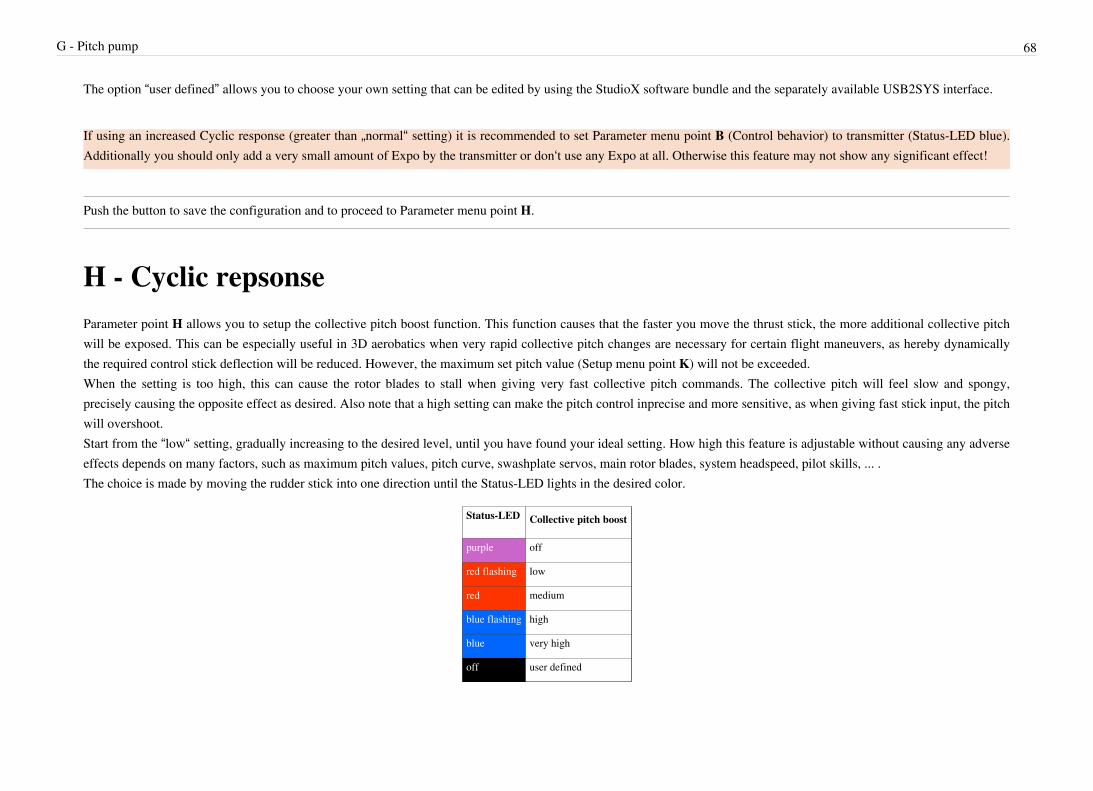
G - Pitch pump 68
The option “user defined” allows you to choose your own setting that can be edited by using the StudioX software bundle and the separately available USB2SYS interface.
If using an increased Cyclic response (greater than „normal“ setting) it is recommended to set Parameter menu point B (Control behavior) to transmitter (Status-LED blue).Additionally you should only add a very small amount of Expo by the transmitter or don‘t use any Expo at all. Otherwise this feature may not show any significant effect!
Push the button to save the configuration and to proceed to Parameter menu point H.
H - Cyclic repsonseParameter point H allows you to setup the collective pitch boost function. This function causes that the faster you move the thrust stick, the more additional collective pitchwill be exposed. This can be especially useful in 3D aerobatics when very rapid collective pitch changes are necessary for certain flight maneuvers, as hereby dynamicallythe required control stick deflection will be reduced. However, the maximum set pitch value (Setup menu point K) will not be exceeded.When the setting is too high, this can cause the rotor blades to stall when giving very fast collective pitch commands. The collective pitch will feel slow and spongy,precisely causing the opposite effect as desired. Also note that a high setting can make the pitch control inprecise and more sensitive, as when giving fast stick input, the pitchwill overshoot.Start from the “low“ setting, gradually increasing to the desired level, until you have found your ideal setting. How high this feature is adjustable without causing any adverseeffects depends on many factors, such as maximum pitch values, pitch curve, swashplate servos, main rotor blades, system headspeed, pilot skills, ... .The choice is made by moving the rudder stick into one direction until the Status-LED lights in the desired color.
Status-LED Collective pitch boost
purple off
red flashing low
red medium
blue flashing high
blue very high
off user defined

H - Cyclic repsonse 69
The option “user defined” allows you to choose your own setting that can be edited by using the StudioX software bundle and the separately available USB2SYS interface.
When no additional features are installed on your unit, pressing the button will save the setting and exit the Parameter menu. Now MICROBEAST PLUS is ready foroperation again!When using MICROBEAST PLUS Version 4 with RPM Governor or ProEdition upgrade, push the button to save the configuration and to proceed to Parameter menu pointI.
I - Throttle responseUse Parameter menu point I to change the response of the RPM Governor control. This determines how fast and hard the system will open the throttle when the rotor rpmchanges. Ideally the response is set as high as possible. If it is too low the main rotor may speed up in unloaded conditions as the system reduces throttle to slowly, and theRPM Governor will only increase throttle very cautious when loading the rotor head, so that the rotor rpm will break down. If on the other hand the response is set too high,the throttle may stutter audible and/or the motor rpm will kick in very hard and overshoot if the rotor head is loaded. This will make the rotor headspeed even moreinconsistent than with a lower setting. The height of throttle response highly depends on factors such as heli size (blade size), motor power and performance and/or thethrottle reponse behavior of the speed controller (when flying an electric heli). If you need to adjust the throttle response, we recommend to start with the lowest value andincrease stepwise just until you get the most consistent rotor head speed. Having a heli with good motor power and/or a fast responding speed controller (on electric helis)typically allows to have high throttle response values (up to "aggressive" setting) which will give very consistent head speed. Helis with not so much power (small nitros,gasser, scale helis) prefer low throttle response settings for a softer throttle management.The choice is made by moving the rudder stick into one direction until the Status-LED lights in the desired color.
Status-LED Throttle response
purple normal
red flashing slightly increased
red increased
blue flashing fast
blue aggressive
off user defined
The option “user defined” allows you to choose your own setting that can be edited by using the StudioX software bundle and the separately available USB2SYS interface.

I - Throttle response 70
Push the button to save the configuration and to proceed to Parameter menu point J.
J - Slow rampup speedWhen activating the RPM Governor this will not apply full throttle immediately but will increase the rotor head speed slowly until the desired preset head speed is reached.At menu point J you can determine how quickly this soft start occurs when the RPM Governor is activated initially. The speed is given in number of revolutions by howmuch the rotor speed is increased per second. The higher the speed the faster your preset head speed will be reached. Please note that the given rates only are indicative.Depending on the response of the speed controller and the inertia of the rotor system it can actually take longer or shorter until the desired speed is reached.The choice is made by moving the rudder stick into one direction until the Status-LED lights in the desired color.
Status-LED Spool up rate
purple 50 rpm/s
red flashing 100 rpm/s
red 200 rpm/s
blue flashing 300 rpm/s
blue 400 rpm/s
off user defined
The option “user defined” allows you to choose your own setting that can be edited by using the StudioX software bundle and the separately available USB2SYS interface.
Push the button to save the configuration and to proceed to Parameter menu point K.

K - Fast rampup speed 71
K - Fast rampup speedIf the RPM Governor is already enabled and you change the preset rotor head speed in the transmitter (i.e. by switching to a different flight mode), there will not be an abruptchange but the system will increase the rotor rpm with a given spool up rate that can be set at menu point K. This rate also determines how fast the rotor head speed willincrease when reactivating the RPM Governor after an autorotation maneuver (Autorotation bailout). In this case the normal soft start (which is set at Setup menu point J)may take too much time until the rotor has reached full speed again as the heli is still in the air, so we use this faster spool up rate instead.The choice is made by moving the rudder stick into one direction until the Status-LED lights in the desired color.
Status-LED Fast spool up rate
purple same as Spool up rate J
red flashing 300 rpm/s
red 500 rpm/s
blue flashing 700 rpm/s
blue 900 rpm/s
off user defined
If you set „same as Spool up rate J“ the spool up rate will then be the same as the rate set at menu point J.The option “user defined” allows you to choose your own setting that can be edited by using the StudioX software bundle and the separately available USB2SYS interface.
A very high spool up rate can cause the throttle to be opened very fast. Especially when recovering from an autorotation maneuver this can cause the rotor blades to foldin or can damage the main gear in (especially electric models), so only increase the value stepwise and with care. With nitro helicopters in general using low values isrecommended (even only the setting „same as Spool up rate J“) as here an abrupt throttle change out of idle position can cause the engine to quit! Additionaly nitro motorsreact quite slow to throttle changes and it takes some time to speed up the rotor. So when the change rate does not fit to the mechanical speed up, it can happen that the motoris driven to full throttle during spool up by accident as the motor does not speed up immediately.
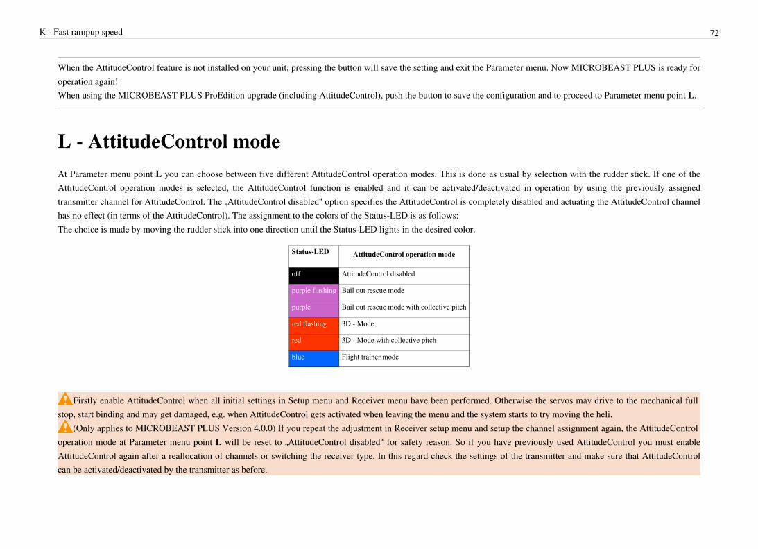
K - Fast rampup speed 72
When the AttitudeControl feature is not installed on your unit, pressing the button will save the setting and exit the Parameter menu. Now MICROBEAST PLUS is ready foroperation again!When using the MICROBEAST PLUS ProEdition upgrade (including AttitudeControl), push the button to save the configuration and to proceed to Parameter menu point L.
L - AttitudeControl modeAt Parameter menu point L you can choose between five different AttitudeControl operation modes. This is done as usual by selection with the rudder stick. If one of theAttitudeControl operation modes is selected, the AttitudeControl function is enabled and it can be activated/deactivated in operation by using the previously assignedtransmitter channel for AttitudeControl. The „AttitudeControl disabled“ option specifies the AttitudeControl is completely disabled and actuating the AttitudeControl channelhas no effect (in terms of the AttitudeControl). The assignment to the colors of the Status-LED is as follows:The choice is made by moving the rudder stick into one direction until the Status-LED lights in the desired color.
Status-LED AttitudeControl operation mode
off AttitudeControl disabled
purple flashing Bail out rescue mode
purple Bail out rescue mode with collective pitch
red flashing 3D - Mode
red 3D - Mode with collective pitch
blue Flight trainer mode
Firstly enable AttitudeControl when all initial settings in Setup menu and Receiver menu have been performed. Otherwise the servos may drive to the mechanical fullstop, start binding and may get damaged, e.g. when AttitudeControl gets activated when leaving the menu and the system starts to try moving the heli.
(Only applies to MICROBEAST PLUS Version 4.0.0) If you repeat the adjustment in Receiver setup menu and setup the channel assignment again, the AttitudeControloperation mode at Parameter menu point L will be reset to „AttitudeControl disabled“ for safety reason. So if you have previously used AttitudeControl you must enableAttitudeControl again after a reallocation of channels or switching the receiver type. In this regard check the settings of the transmitter and make sure that AttitudeControlcan be activated/deactivated by the transmitter as before.

L - AttitudeControl mode 73
Bail out rescue modeThis operation mode can be used if the pilot becomes disoriented and would like to save the helicopter from crashing. In such case he just needs to let go the stick(s) foraileron and elevator and activate the AttitudeControl by flipping the assigned switch for AttitudeControl function. The helicopter then is rotated back into normal horizontalposition by the shortest route over roll or pitch. The pilot must only operate the collective pitch function to control the height of the helicopter. Note that for safety reasonthere is a stick fading implemented. Even when AttitudeControl is switched on you can control aileron and elevator. The stick movements have priority over theAttitudeControl. The larger the deflection of the corresponding control stick, the less effect AttitudeControl has. On the other hand when both sticks are in center positionAttitudeControl takes over full control of the aileron and elevator function.
Bail out rescue mode with collective pitch controlBail out rescue mode with collective pitch control provides the same functionality as the „Bail out rescue mode“ described above. In addition, here the AttitudeControl alsocontrols the collective pitch function. During the rotation and after reaching the horizontal position, AttitudeControl inputs positive or negative collective pitch, making thehelicopter turn (almost) without loss of height and maintain hover position (or slightly climping up) when horizontal position is reached. So the pilot can completely let go allsticks as soon as he activates AttitudeControl and the helicopter is automatically brought into a (relatively) save location by AttitudeControl. Here it is possible to add somecollective pitch and let the heli climb up even faster by moving the thrust stick beyond the point that is applied by AttitudeControl. But moving the thrust stick lower islocked as you can never apply less collective pitch than AttitudeControl does. So the helicopter can not be moved towards the ground by giving wrong collective pitch inputsby accident.
3D - ModeIn 3D - Mode MICROBEAST PLUS recognizes the current orientation of the heli (normal or inverted) and always rotates the helicopter to the nearest horizontal positionwhen AttitudeControl is activated. This operation mode is well suited for practicing basic 3D - aerobatic maneuvers such as hovering or back flips. Since in 3D - Mode thestabilization can be fully overridden when actuating aileron or elevator function, it is possible to keep 3D - Mode activated for a longer period of time and to grope at anaerobatic maneuvers by only giving specific control inputs. Rolling and pitching back to horizontal position then does AttitudeControl for you. The pilot must only controlcollective pitch and rudder. In addition, you can use this mode as rescue mode to stabilize the helicopter in an emergency situation. It should be noted, however, that the heliis always rotated to the nearest horizontal position. Therefore you must be very careful in controlling the collective pitch function as it may happen by accident that you givea collective input to the wrong direction. If you want to use 3D - Mode exclusively as rescue function, it is recommended to use 3D - Mode with collective pitch control.

L - AttitudeControl mode 74
3D - Mode with collective pitch control3D - Mode with collective pitch control provides the same functionality as the „3D - Mode“. In addition, here AttitudeControl takes over the collective pitch function. Whenreaching horizontal position AttitudeControl gives a positive or negative pitch input, so that the heli is held in the hover position or climbs up slightly. Here, the thrust stick islocked into each „wrong“ direction. Therefore the pilot can only give additional collective pitch input (in normal position positive, in inverted position negative pitch) toincrease the climb rate of the helicopter. But he cannot move the helicopter towards the ground by accidentally giving wrong pitch inputs.
Flight trainer modeIn Flight trainer mode you can only tilt the helicopter to a certain angle by giving aileron or elevator stick input. Moving the helicopter even further is impossible, as long asAttitudeControl is active. This prevents the helicopter from being tilted into a lateral position that may cause a big loss of height. As soon as the stick(s) for aileron andelevator is (are) released, the helicopter will be brought back to horizontal position by AttitudeControl. Additionally the helicopter is stablized all the time, independant ofany stick input. This together makes the helicopter fly very similar to a multirotor helicopter. The pilot does not have to focus on the constant need of correcting thehelicopter‘s attitude and he can not bring the helicopter in a difficult attitude by making violent control maneuvers. Collective pitch and rudder are not affected by thisoperation mode.
Please note that the system is not capable of holding the helicopter over an absolute position. It is very likely the helicopter will drift to one side or another due toexternal influences or simply due to the instability of the helicopter. The system only keeps the helicopter in a nearly horizontal level position as long as you don't touch thecyclic sticks and brings it back to such position as soon as you release the sticks for cyclic input. This position may vary slightly due to sensor drift caused by vibrations ortemperature change and the helicopter may be slightly tilted to one or another directions and not be perfectly level. So although the flight trainer mode can be used as aid forbeginner training you mustn't fully depend on the system. A basic knowledge and skill of piloting a helicopter is mandatory. The system is not a autopiloting device, therewill be situations that require control actions from the pilot. If you are a beginner pilot only use the system under supervision of an experienced pilot and in combination witha buddy box system.
If you selected Bail out rescue mode with collective pitch or 3D - Mode with collective pitch pushing the button will save the configuration and lead to Parameter menupoint M for adjusting the collective pitch for the AttitudeControl mode. Otherwise pushing the button will save the configuration and exit Parameter menu. Then the device iswill be back in operation mode.
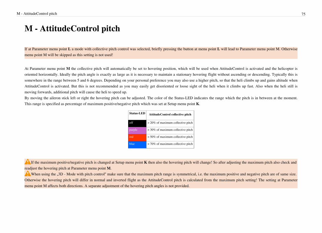
M - AttitudeControl pitch 75
M - AttitudeControl pitch
If at Parameter menu point L a mode with collective pitch control was selected, briefly pressing the button at menu point L will lead to Parameter menu point M. Otherwisemenu point M will be skipped as this setting is not used!
At Parameter menu point M the collective pitch will automatically be set to hovering position, which will be used when AttitudeControl is activated and the helicopter isoriented horizontally. Ideally the pitch angle is exactly as large as it is necessary to maintain a stationary hovering flight without ascending or descending. Typically this issomewhere in the range between 5 and 6 degrees. Depending on your personal preference you may also use a higher pitch, so that the heli climbs up and gains altitude whenAttitudeControl is activated. But this is not recommended as you may easily get disoriented or loose sight of the heli when it climbs up fast. Also when the heli still ismoving forwards, additional pitch will cause the heli to speed up.By moving the aileron stick left or right the hovering pitch can be adjusted. The color of the Status-LED indicates the range which the pitch is in between at the moment.This range is specified as percentage of maximum positive/negative pitch which was set at Setup menu point K.
Status-LED AttitudeControl collective pitch
off > 20% of maximum collective pitch
purple > 30% of maximum collective pitch
red > 50% of maximum collective pitch
blue > 70% of maximum collective pitch
If the maximum positive/negative pitch is changed at Setup menu point K then also the hovering pitch will change! So after adjusting the maximum pitch also check andreadjust the hovering pitch at Parameter menu point M.
When using the „3D - Mode with pitch control“ make sure that the maximum pitch range is symmetrical, i.e. the maximum positive and negative pitch are of same size.Otherwise the hovering pitch will differ in normal and inverted flight as the AttitudeControl pitch is calculated from the maximum pitch setting! The setting at Parametermenu point M affects both directions. A separate adjustment of the hovering pitch angles is not provided.

M - AttitudeControl pitch 76
Push the button to save the configuration and exit Parameter menu. Then the device will be back in operation mode.

77
Governor setup menuWith MICROBEAST PLUS you have purchased an electronic control system that continuously detects and controls the commands from the pilot. As a result the system isconstantly aware of how the drive system will be burdened. The RPM Governor system uses this advantage to control the motor rpm. Contrary to conventional motorcontrol systems that only monitor the engine speed, MICROBEAST PLUS can thus react sooner to speed changes. A separate engine governor system is no longer requiredfor nitro helicopters and electric models can be used with a simple (cheap) speed controller without additional features such as soft start or governor mode. The desired rotorspeed is specified via the remote control transmitter and MICROBEAST PLUS controls the throttle servo or speed controller accordingly, so that the predetermined headspeed is maintained from takeoff to landing. MICROBEAST PLUS offers an integrated soft start for spooling up the rotor before takeoff and a quick start to regain headspeed in a controlled manner when practicing autorotation maneuvers. The system is suitable both for electric and nitro/gas helicopters. Using the proven „Easy Setup“concept no additional equipment is required for programming (apart from your remote control system) and the initial setup is done within minutes.If the RPM Governor was activated at Setup menu point N (setting „electric“ or „nitro“) then you can access the Governor menu immediately afterwards. Here varioushelicopter specific information must be provided which is necessary so that the RPM Governor can function correctly. Moreover, the transmitter will be prepared for the usewith the RPM Governor function and at menu point A a function test for the rpm sensor is performed.Note: Setup menu point N and in consequence the Governor setup menu points are only accessible if you have installed the RPM Governor feature on your device and incase you're using a single-line receiver. The RPM Governor function is not applicable when a Standard receiver is used!
Pay attention to your own safety and the safety of other people and property in your vicinity when using our product. When using helicopters with nitro/gas enginesmake sure that the motor will not start when making adjustments to the system. When using a gas engine always keep the ignition system deactivated!
For electric helicopters remove the motor pinion from the main gear during initial setup. Warning! Risk of injury! Never touch the motor when it‘s running. Alwayskeep a save distance to all rotating parts of the helicopter.
A - Test mode 78
A - Test modeThus the RPM Governor of MICROBEAST PLUS can be used, the system must be able to detect the motor speed. This is done with the help of a rpm sensor that must beattached to the sensor input of MICROBEAST PLUS. For models with nitro/gas engines usually sensors are used that determine the speed signal magnetically or optically.These sensors are mounted next to the crankshaft or clutch bell and register the number of engine revolutions here. For electric motors the motor speed can be determinedelectronically. For this purpose a phase sensor (e.g. BXA76013) is connected to one or two of the motor phases. Some electric speed controllers also offer a direct signaloutput for the rpm signal, so that no additional sensor is required.To see how the sensor is mounted in detail please refer to the instruction manual from the sensor or from the helicopter. The wire with the rpm signal is connected to sensorinput pin at the sideport of MICROBEAST PLUS by using the optional adapter cable BXA76401. This sideboard also powers the sensor with the supply voltage, ifnecessary. Note that the height of the supply voltage corresponds to your receiver power supply voltage!Here are some installation and connection examples. As described virtually all kinds of rpm sensors may be used. Unfortunately it is impossible to try and enumerate alltypes. If in doubt about whether a particular sensor can be used in conjunction with MICROBEAST PLUS ask your dealer to find out.
Electric drive system with external phase sensorConnect the motor wires of the phase sensor with any two phases of the electric motor. It is recommended to solder those wires to the plugs of the speed controller. So formaintenance purposes it is easier to remove the motor from the model later. In some cases the use of only one phase wire is sufficient. Usually this is the case when the speedcontroller powers the system with a BEC thus there is no galvanic isolation between motor and receiver circuit. However, we recommend using both wires in any case! Thisensures that the sensor provides an interference-free signal as possible.The electronic speed controller is plugged into the [CH5] output.

A - Test mode 79

A - Test mode 80
Electric drive system with rpm signal output from the speed controllerWhen a speed controller is used that provides a rpm signal output you can alternatively use the [RPM] sensor input on the front connection board of MICROBEAST PLUS(lowest pin of the tripple signal input). (RPM sensors can‘t be connected here as this pin header does not provide any power supply!) The speed controller‘s signal input wireis plugged into the output [CH5] as usual.

A - Test mode 81
Combustion drive system (nitro/gas)Particularly when using sensors for combustion engines check for correct polarity of the sensor power supply on the adapter cable BXA76401. Here commonly sensors areused that are designed for governor systems from other manufacturers and therefore have a special pin assignment. In this case the colors of the connecting cables may notfollow the norm (The wire colors of the ALIGN governor sensor HE50H22 are swapped for example. Here red denotes the negative and black the positive pole!).
Sensor function testAt menu point A we check whether the rpm sensor is functioning properly and the rpm sensor wire is connected correctly and in general if there is a usable rpm signal. Watch out! At this menu point the throttle channel is unlocked. This means you have full control over the throttle output [CH5] with your remote control to control the speed controller or throttle servo. When using an electric model it is necessary to increase the throttle until the motor starts to rotate and the phase sensor or the speed controller outputs a rpm signal. Once the motor is running the Status-LED on the MICROBEAST PLUS should light up in red color. With a nitro/gas powered helicopter you can simply rotate the clutch or engine crankshaft by hand until the signal generator (magnet or similar) passes the sensor. Whenever

A - Test mode 82
the signal generator is within the detection range of the sensor the Status-LED should light up in blue color. If the Status-LED on the MICROBEAST PLUS does not light up as described please double check the wiring. Particularly pay attention whether the power wires of thesensor are of correct polarity (on some sensors the wire colors do not match the usual standard!). If you have a magnetic sensor check if the magnets are installed with thecorrect polarity and if they are passing the front of the sensor close enough. Using a crankshaft sensor make sure that the sensor is mounted close enough to the frameaccordingly. In addition to the function control of the sensor, check the throw setting for the throttle servo in the remote control and adjust if necessary: Set the throttle to mid stickposition and attach the servo horn, so that the throttle linkage is at a right angle to the servo horn. Then adjust the length of the linkage according to the instructions of thehelicopter, so that it also is positioned perpendicular to the linkage lever at the carburetor. Adjust the lever at the carburetor so that it is opened halfways (note the markingson the carburetor!). Now move the throttle stick towards full throttle and adjust the servo travel in the transmitter accordingly, so that the full throttle position is reachedwithout binding. Lastly move both throttle stick and throttle trim on the transmitter to the „motor off“ position and also adjust the servo travel in that direction until thecarburetor is fully closed. If the servo travel must be greatly reduced in both directions, it is recommended that the linkage ball on the servo arm is mounted further in so thatthe servo can be moved over a wider range. For more information refer to the instruction manual for your helicopter.

A - Test mode 83
Also with an electric model, the control range of throttle is crucial. Usually here the throttle endpoints of the transmitter are fixed by an initial programming of the speedcontroller. But also speed controller exist that require adjusting the servo throw of throttle channel in the transmitter, so that the throttle range is in accordance with thespecification of the speed controller. At menu point A there is the possibility to check again whether this setting has been performed correctly. Carefully apply some gas. Themotor should start to turn immediately if you move the stick just a little bit and full speed should be reached when the stick just reaches full throttle position. If the engineturns much earlier at the maximum possible speed or only starts to turn at a very high stick deflection decrease the travel of throttle channel in the transmitter or repeat theprogramming of the speed controller. Thus the RPM Governor of MICROBEAST PLUS can operate correctly, the motor speed should increase as linear as possible when thestick is moved and there should be no ranges in that the motor speed does not change.
Watch Out! Electric motors rotate at high speeds. Keep a safe distance during the function test. We highly recommend to remove the motor from the main gear.However, please observe the manufacturer‘s specifications of the motor. Some motors may not be operated without load. In this case only let the motor run for a short time orlet the motor stay attached to the main gear and only remove the main and tail rotor blades (Warning! Increased risk of injury).If in doubt, do without the function test and throttle stick position check.
When finished briefly push the button to save the configuration and to proceed to Governor setup menu point B.

B - Throttle low position 84
B - Throttle low positionMenu point B is used to set the lowest throttle position. Watch Out! Output [CH5] can be directly controlled by the throttle stick.Using an electric model bring the throttle stick to the position at which the motor just does not start. If the stick throw has been correctly adjusted as described at menu pointA (or the speed controller has been programmed to the stick throws), the necessary gas position should be achieved at the lowest position of the throttle stick. Some speedcontrollers provide a special mode that allows for a quick start-up in case of aborting an autorotation landing. Here there is a larger area between the actual „motor off“position of the speed controller and the point at which the motor actually starts. Also in this case move the throttle stick to the point at which the motor is just before to start,so that MICROBEAST PLUS can determine the effective throttle range correctly.With a nitro/gasser model you bring the throttle stick to idle position or a slightly increased idle position (not „motor off“!) so MICROBEAST PLUS can determine theeffective throttle range in the next step. Using the RPM Governor without an auxiliary channel to control the RPM Governor (see Receiver setup menu point B andfollowing), this position additionaly will be used as idle position when performing an autorotation maneuver. So you should set the throttle as high as necessary here that themotor will maintain a stable run and doesn‘t quit during the autorotation maneuver.When setting the low throttle position make sure the Status-LED lights up in blue color (both electrical as well as nitro). This means that a new valid throttle position hasbeen detected. If the Status-LED lights up in red then the throttle stick is too close to the throttle stick center position. This is not considered optimal and therefore can not beused as throttle position. In this case check the setting of the transmitter and the programming of the speed controller or readjust throttle servo, carburetor position andthrottle linkage rod.
When entering menu point B initially the Status-LED is off. As long as you do not move the throttle stick, the currently stored position will not be changed. So you can skipmenu point B by a brief push of the button without changing the throttle position when performing subsequent adjustments in Setup menu or Governor setup menu.Conversely this means that you need to move the throttle stick at menu point B at least once to change the current throttle position!
When finished briefly push the button to save the configuration and to proceed to Governor setup menu point C.

C - Throttle high position 85
C - Throttle high positionAt menu point C you have to set full throttle position of your ESC or throttle servo. Here the output [CH5] can be only controlled by the throttle stick when the RPMGovernor type is set to „nitro“. In „electric“ mode the throttle output will stay locked to your low throttle value. So you can set the full throttle position quite comfortablewithout the motor running high. Otherwise there are no differences between the modes „electric“ and „nitro“.Move the throttle stick to full throttle position. The Status-LED must light up in blue color. This means that a new valid throttle position has been detected. If the Status-LEDlights up in red the distance between the lowest throttle position and the full throttle position is too small. Since this will have a negative effect on the control behavior of thesystem, this throttle position can not be used. In this case check the setting of the transmitter and the programming of the speed controller or readjust throttle servo, carburetorposition and throttle linkage rod. If necessary, set the lowest throttle position at menu point B again.
Similar to menu point B the Status-LED is off when entering menu point C. As long as you do not move the throttle stick, the currently stored position will not be changed.So you can skip menu point C by a brief push of the button without changing the throttle position when performing subsequent adjustments in Setup menu or Governor setupmenu. Conversely this means that you need to move the throttle stick at menu point C at least once to change the current full throttle position!
When finished briefly push the button to save the configuration and to proceed to Governor setup menu point C.

D - Switch point display 86
D - Switch point displaySimilar to menu point A, menu point D only serves to give you some status information. At menu point D the different activation points of the RPM Governor will bedisplayed based on color and state of the Status-LED. So you can prepare your transmitter for use with the RPM Governor function. The information conveyed by theStatus-LED is basically the same in every Governor operation mode. However, the setup of the transmitter will be slightly different, depending on whether the mode electricor nitro is used.
Electric GovernorIn electric governor mode the pilot does no longer control the speed controller with the transmitter. MICROBEAST PLUS completely takes over control of the ESC. Withthe transmitter you only specifiy the desired rotor rpm you want the helicopter to maintain. When setting a rpm higher than zero, MICROBEAST PLUS will speed up therotor smoothly and ensure that the demanded rotor rpm is kept constant throughout the flight. To practice autorotation landings, additionaly you can keep MICROBEASTPLUS in a special mode that causes the speed controller to be switched off during the maneuver but speed up the rotor rpm fast when aborting the autorotation (faster thanwith the initial soft start).The rotor rpm is set via the throttle channel of the transmitter. You may use the transmitter‘s throttle curves for instance, so you can switch the motor on and off and pretenddifferent speeds using the flight mode system of the transmitter. Instead of curves you only have to set horizontal lines so that the rotor rpm value does not depend on thethrottle stick position but is fixed in each flight mode. The flight mode switch then acts as a switch that switches between different speed settings.
In electric mode the adjustable throttle range is 3400 rpm/min. The lowest rotor speed that can be set is 600rpm/min, the maximum speed is 4000rpm/min. To enableautorotation bail out mode the throttle must be set to a value between 5% and 15%.

D - Switch point display 87
Throttle position(scale depending on transmitter)
Rotor rpm Status-LED
100% +100 4000 purple
95% +90 3800 red
90% +80 3600
85% +70 3400
80% +60 3200
75% +50 3000
70% +40 2800
65% +30 2600
60% +20 2400
55% +10 2200
50% 0 2000
45% -10 1800
40% -20 1600
35% -30 1400
30% -40 1200
25% -50 1000
20% -60 800
15% -70 600
10% -80 Motor off/Autorotation
blue
5% -90
0% -100 Motor off off
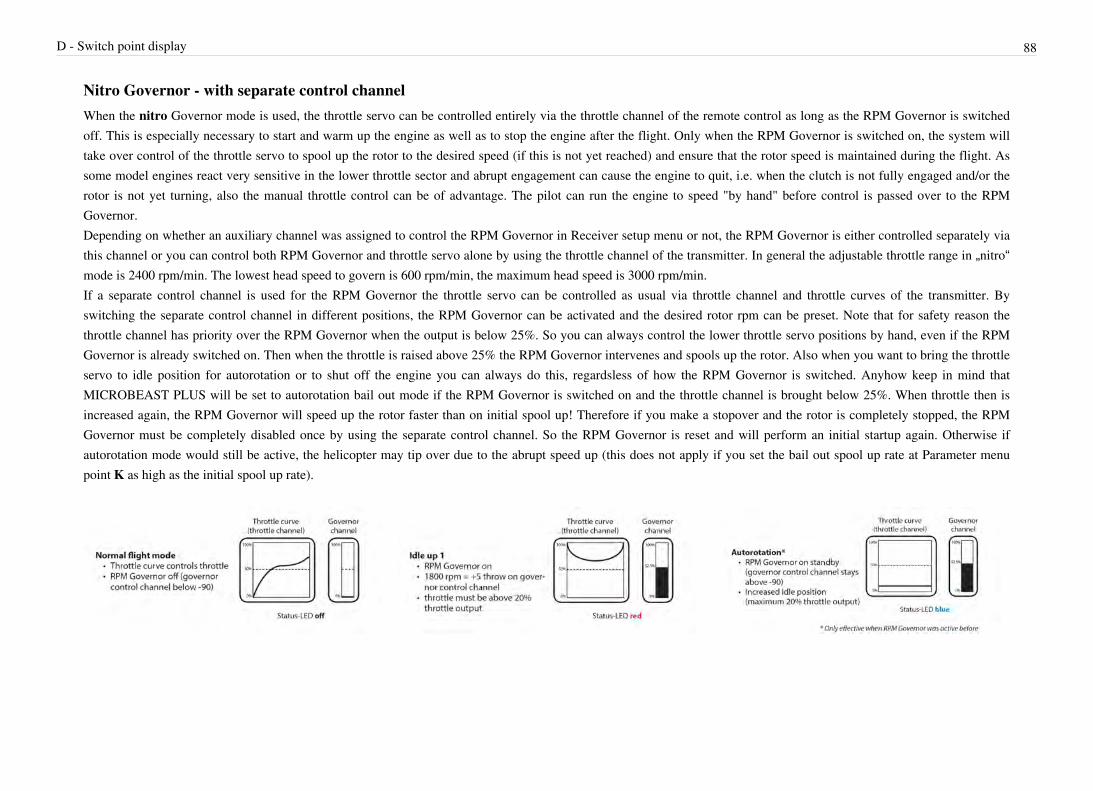
D - Switch point display 88
Nitro Governor - with separate control channelWhen the nitro Governor mode is used, the throttle servo can be controlled entirely via the throttle channel of the remote control as long as the RPM Governor is switchedoff. This is especially necessary to start and warm up the engine as well as to stop the engine after the flight. Only when the RPM Governor is switched on, the system willtake over control of the throttle servo to spool up the rotor to the desired speed (if this is not yet reached) and ensure that the rotor speed is maintained during the flight. Assome model engines react very sensitive in the lower throttle sector and abrupt engagement can cause the engine to quit, i.e. when the clutch is not fully engaged and/or therotor is not yet turning, also the manual throttle control can be of advantage. The pilot can run the engine to speed "by hand" before control is passed over to the RPMGovernor.Depending on whether an auxiliary channel was assigned to control the RPM Governor in Receiver setup menu or not, the RPM Governor is either controlled separately viathis channel or you can control both RPM Governor and throttle servo alone by using the throttle channel of the transmitter. In general the adjustable throttle range in „nitro“mode is 2400 rpm/min. The lowest head speed to govern is 600 rpm/min, the maximum head speed is 3000 rpm/min.If a separate control channel is used for the RPM Governor the throttle servo can be controlled as usual via throttle channel and throttle curves of the transmitter. Byswitching the separate control channel in different positions, the RPM Governor can be activated and the desired rotor rpm can be preset. Note that for safety reason thethrottle channel has priority over the RPM Governor when the output is below 25%. So you can always control the lower throttle servo positions by hand, even if the RPMGovernor is already switched on. Then when the throttle is raised above 25% the RPM Governor intervenes and spools up the rotor. Also when you want to bring the throttleservo to idle position for autorotation or to shut off the engine you can always do this, regardsless of how the RPM Governor is switched. Anyhow keep in mind thatMICROBEAST PLUS will be set to autorotation bail out mode if the RPM Governor is switched on and the throttle channel is brought below 25%. When throttle then isincreased again, the RPM Governor will speed up the rotor faster than on initial spool up! Therefore if you make a stopover and the rotor is completely stopped, the RPMGovernor must be completely disabled once by using the separate control channel. So the RPM Governor is reset and will perform an initial startup again. Otherwise ifautorotation mode would still be active, the helicopter may tip over due to the abrupt speed up (this does not apply if you set the bail out spool up rate at Parameter menupoint K as high as the initial spool up rate).

D - Switch point display 89
Throttle position(scale depending on transmitter)
100% +100 Manual control/
RPM control95% +90
90% +80
85% +70
80% +60
75% +50
70% +40
65% +30
60% +20
55% +10
50% 0
45% -10
40% -20
35% -30
30% -40
25% -50
20% -60 Manual control/
Autorotation15% -70
10% -80
5% -90
0% -100

D - Switch point display 90
Rotor rpm Governorchannel
3000 +100
2874 +90
2747 +80
2621 +70
2495 +60
2368 +50
2242 +40
2116 +30
1989 +20
1863 +10
1737 0
1611 -10
1484 -20
1358 -30
1232 -40
1105 -50
979 -60
853 -70
726 -80
600 -90
aus -100

D - Switch point display 91
Nitro Governor - simple modeIf no separate control channel is used for the RPM Governor, throttle servo and RPM Governor are solely controlled by the throttle channel. For this purpose the controlrange of the throttle channel is divided into two parts: Below the center position, the throttle servo is controlled manually by the throttle channel. The RPM Governor isswitched off and the servo output range is doubled, so that the throttle servo can be moved over the entire range. Once the throttle channel is moved (switched) to the upperarea, the RPM Governor will activate, spool up the rotor and try to hold the preset rpm. Similar as it was described above for electric models you make the throttle curve ahorizontal line, so that regardless of the position of the throttle stick MICROBEAST PLUS will always see the same throttle value and so the preset rpm will stays the same.So at least two flight phases are necessary. One that the throttle curve goes only up to the middle and in which the motor can be controlled by hand, i.e. for starting the motorand one flight phase that activates the RPM Governor and the throttle curve is used to preset the desired rotor head speed.
A third flight mode is used for auto-rotation: Here the throttle channel is constantly set to a value close below center position (between 40% and 50%) . When you switch to this flight mode once the governor was active, the throttle servo will be moved to the idle position set at menu point B. When switching back to governor mode, i.e. when you want to bail out from autorotation, the rotor will be spooled up at an increased rate (this does not apply if you set the bail out spool up rate at Parameter menu point K as high as the initial spool up rate - see chapter 8). Alternatively if it is switch back to the flight phase with manual control, autorotation mode is canceled and the next time you switch on the RPM Governor, the rotor is spooled up slowly.

D - Switch point display 92
Throttle position(scale depending on transmitter)
Rotor rpm Status-LED
100% +100 3000 purple
95% +90 2760 red
90% +80 2520
85% +70 2280
80% +60 2040
75% +50 1800
70% +40 1560
65% +30 1320
60% +20 1080
55% +10 840
50% 0 600
45% -10 Manualcontrol/
Autorotation
blue
40% -20

D - Switch point display 93
35% -30 Manual control off
30% -40
25% -50
20% -60
15% -70
10% -80
5% -90
0% -100
When finished briefly push the button to proceed to Governor setup menu point E.
E - Signal dividerWhen using electric motors the rpm sensor signal usually consists of the (electric) field speed. In order to obtain the actual engine speed the field speed must be divided byhalf the number of motor poles. Using a 2-pole motor thus the measured speed corresponds to the motor speed. With a 10-pole motor on the other hand the field speed is fivetimes higher than the actual speed. Also for nitro/gas engines the measured speed of the sensor may be higher than the actual speed. For example when a magnetic sensor isinstalled and more than one magnets are used for measuring the rotational speed, the rpm output will be multiplied by the number of magnets. So when two sensor magnetsare used the rpm signal from the sensor will be twice the engine revolutions.At menu point E you must specifiy the factor by how much the incoming rpm signal must be divided to get the actual motor rpm. The currently selected division factor isrepresented by the color of the Status-LED. Use the rudder stick to switch between options.

E - Signal divider 94
Status-LED RPM Divider
off no division2 motor poles (electric) or 1 magnet (nitro)
purple flashing 24 motor poles (electric) or 2 magnets (nitro)
purple 36 motor poles
red flashing 48 motor poles
red 510 motor poles
blue flashing 612 motor poles
blue 714 motor poles
The motor poles of an electric motor can be easily determined by counting the number of magnets built into the motor housing. Each magnet corresponds to one magneticpole. Note that on some motors pairs of magnets are used rather than one single large magnet. These pairs together form just one magnetic pole! If in doubt refer to thedatasheet of the motor or ask the manufacturer or your local dealer.To determine the number of magnets that are used for a magnetic rpm sensor in a nitro helicopter, you can use menu point A. Each time a magnet passes the sensor theStatus-LED will light up in blue color there, i.e. when you turn the clutch bell by hand. So you simply count how often the Status-LED lights up during one rotation. Thenthis is the divider you have to set a menu point E.
When finished briefly push the button to proceed to Governor setup menu point F.
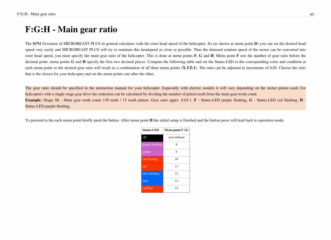
F:G:H - Main gear ratio 95
F:G:H - Main gear ratioThe RPM Governor of MICROBEAST PLUS in general calculates with the rotor head speed of the helicopter. So (as shown at menu point D) you can set the desired headspeed very easily and MICROBEAST PLUS will try to maintain this headspeed as close as possible. Thus the detected rotation speed of the motor can be converted intorotor head speed, you must specify the main gear ratio of the helicopter. This is done at menu points F, G and H. Menu point F sets the number of gear ratio before thedecimal point, menu points G and H specify the first two decimal places. Compare the following table and set the Status-LED to the corresponding color and condition ateach menu point so the desired gear ratio will result as a combination of all three menu points (X.YZ:1). The ratio can be adjusted in increments of 0.05. Choose the ratiothat is the closest for your helicopter and set the menu points one after the other.
The gear ratio should be specified in the instruction manual for your helicopter. Especially with electric models it will vary depending on the motor pinion used. Forhelicopters with a single-stage gear drive the reduction can be calculated by dividing the number of pinion teeth from the main gear tooth count.Example: Shape S8 - Main gear tooth count 130 teeth / 15 tooth pinion. Gear ratio apprx. 8.65:1. F - Status-LED purple flashing, G - Status-LED red flashing, H -Status-LED purple flashing.
To proceed to the each menu point briefly push the button. After menu point H the initial setup is finished and the button press will lead back to operation mode.
Status-LED Menu point F (X)
off user defined
purple flashing 8
purple 9
red flashing 10
red 11
blue flashing 12
blue 13
red/blue 14

F:G:H - Main gear ratio 96
Menu point GStatus-LED
YZ Menu point HStatus-LED
off .00 off
off .05 purple flashing
off .10 purple
off .15 red flashing
purple flashing .20 off
purple flashing .25 purple flashing
purple flashing .30 purple
purple flashing .35 red flashing
purple .40 off
purple .45 purple flashing
purple .50 purple
purple .55 red flashing
red flashing .60 off
red flashing .65 purple flashing
red flashing .70 purple
red flashing .75 red flashing
red .80 off
red .85 purple flashing
red .90 purple
red .95 red flashing
Setting the option „user defined“ at menu point F you can choose a custom gear ratio that can be edited by using the StudioX software and the optional USB2SYS interface.This allows to choose ratios smaller than 8.00:1 or greater than 14.95:1 or a ratio that is not a multiplier of 0.05. In this case the menu points G and H will be skipped whenthe button is briefly pressed at menu point F.
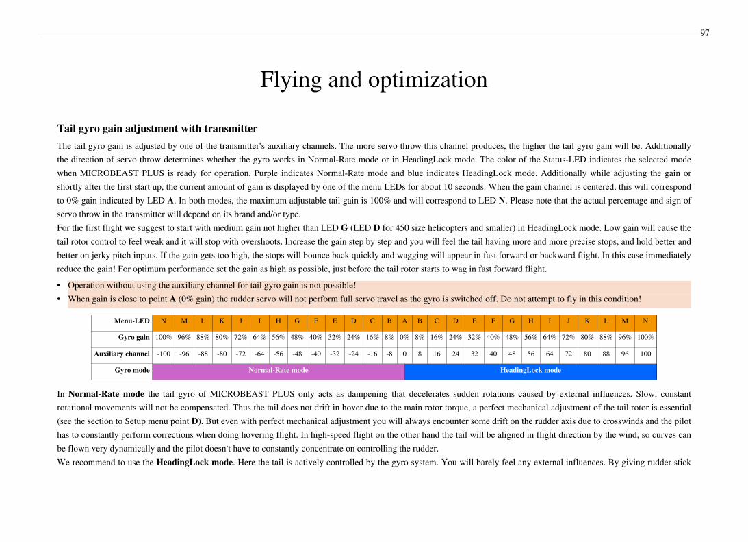
97
Flying and optimization
Tail gyro gain adjustment with transmitterThe tail gyro gain is adjusted by one of the transmitter‘s auxiliary channels. The more servo throw this channel produces, the higher the tail gyro gain will be. Additionallythe direction of servo throw determines whether the gyro works in Normal-Rate mode or in HeadingLock mode. The color of the Status-LED indicates the selected modewhen MICROBEAST PLUS is ready for operation. Purple indicates Normal-Rate mode and blue indicates HeadingLock mode. Additionally while adjusting the gain orshortly after the first start up, the current amount of gain is displayed by one of the menu LEDs for about 10 seconds. When the gain channel is centered, this will correspondto 0% gain indicated by LED A. In both modes, the maximum adjustable tail gain is 100% and will correspond to LED N. Please note that the actual percentage and sign ofservo throw in the transmitter will depend on its brand and/or type.For the first flight we suggest to start with medium gain not higher than LED G (LED D for 450 size helicopters and smaller) in HeadingLock mode. Low gain will cause thetail rotor control to feel weak and it will stop with overshoots. Increase the gain step by step and you will feel the tail having more and more precise stops, and hold better andbetter on jerky pitch inputs. If the gain gets too high, the stops will bounce back quickly and wagging will appear in fast forward or backward flight. In this case immediatelyreduce the gain! For optimum performance set the gain as high as possible, just before the tail rotor starts to wag in fast forward flight.•• Operation without using the auxiliary channel for tail gyro gain is not possible!• When gain is close to point A (0% gain) the rudder servo will not perform full servo travel as the gyro is switched off. Do not attempt to fly in this condition!
Menu-LED N M L K J I H G F E D C B A B C D E F G H I J K L M N
Gyro gain 100% 96% 88% 80% 72% 64% 56% 48% 40% 32% 24% 16% 8% 0% 8% 16% 24% 32% 40% 48% 56% 64% 72% 80% 88% 96% 100%
Auxiliary channel -100 -96 -88 -80 -72 -64 -56 -48 -40 -32 -24 -16 -8 0 8 16 24 32 40 48 56 64 72 80 88 96 100
Gyro mode Normal-Rate mode HeadingLock mode
In Normal-Rate mode the tail gyro of MICROBEAST PLUS only acts as dampening that decelerates sudden rotations caused by external influences. Slow, constant rotational movements will not be compensated. Thus the tail does not drift in hover due to the main rotor torque, a perfect mechanical adjustment of the tail rotor is essential (see the section to Setup menu point D). But even with perfect mechanical adjustment you will always encounter some drift on the rudder axis due to crosswinds and the pilot has to constantly perform corrections when doing hovering flight. In high-speed flight on the other hand the tail will be aligned in flight direction by the wind, so curves can be flown very dynamically and the pilot doesn‘t have to constantly concentrate on controlling the rudder. We recommend to use the HeadingLock mode. Here the tail is actively controlled by the gyro system. You will barely feel any external influences. By giving rudder stick

98
input, the pilot only commands the gyro how fast it has to turn the tail. When the stick is in center position the tail gyro will ensure that the tail keeps locked into position byany means. This simplifies the control significantly. In hovering flight the beginner can fully concentrate on the control of cyclic and collective pitch and the advanced pilotcan perform 3D - flight maneuvers such as backwards flying quite easily. The only disadvantage of HeadingLock-Mode is that the rudder must be steered by the pilot whenflying curves. Otherwise the gyro will try to keep the tail aligned with the initial direction.
To gain better tail gyro performance also check for correct servo horn length. If the tail gain in general is very low and the rudder tends to oscillate very easily move thelinkage ball on the servo horn further inwards to the center. If on the other hand you have a very large amount of tail gain and the tail gyro still does not seem to be capable tohold the tail rotor in any flight condition, move the linkage ball on the servo horn further out from the center, to get faster response speed when the gyro needs to control therudder. Also you may use different (larger) tail rotor blades or higher tail rotor speed to gain better holding force.
Adjusting the dials

99
To adjust the dials please only use the supplied plastic BEASTX adjustment tool to prevent damage to the dials!Dial 1: Cyclic gainThe swash gyro gain (cyclic gain) can be set by dial 1 from 50% up to 150%. Turn dial 1 clockwise to increase the gain. The factory setting is horizontal which correspondsto 100% swashplate gain. For your first flights we suggest not changing this setting. However, when using very small helicopters (such as 250 or 450 size), reduce the cyclicgain by 3 marks (=75% gain) as with such small helicopters the control loop tends to overcompensate more easily.In general the higher the gain the harder the helicopter will stop after cyclic moves and the helicopter will fly more stable and exact in the air. If the gain is too high, thehelicopter will tend to oscillate at high frequency especially on the elevator axis. Due to their low mass, this behavior will occur sooner on small helicopters, so typicallythese do not need as much gain as large helicopters.If the gain is too low the helicopter does not stop precisely and overshoots the more or less after a cyclic movement. Additionally it feels unstable and sluggish in fastforward flight and when hovering. In general low gain will allow the helicopter to have more life of its own and so it will not react to stick inputs as precise and immediate asthe pilot expects it.Dial 2: Cyclic feed forwardThis part mixes some amount of stick input directly to the servos, bypassing the control loop. If correctly adjusted, this relieves the control loop which will work moreefficiently by only having to make residual corrections. Factory setting of the dial is horizontal which provides a good setup in most cases. Turn dial 2 clockwise to increasethe cyclic feed forward. This will cause more cyclic stick input going directly to aileron and elevator on the swashplate. Decreasing the direct stick feed forward will do theopposite.If the cyclic feed forward is too high the stick input will over control the cyclic input. Eventually the control loop needs then to steer back and compensate the unwantedcyclic movement. Even though you get the impression to have a more direct and immediate control over the servos with high feed forwared values, unwanted side effectsmay appear, like pitch backs on cyclic stops and imprecise fast forward flight that show the control loop not working properly.If the direct cyclic feed forward is too low, the helicopter will feel softer, slower and less direct. The optimal point depends of many factors like blades, servos, head speed,size and mass of the helicopter. Ideally you can increase the feed forward just as high as possible without any side effects happening. So you get a quite natural stick feelingand on the other hand the control loop is supported as good as possible. At delivery the dial is in the middle which should be a good starting point for most helicopters.Before adjusting the cyclic feed forward you should try to find the optimal maximum cyclic gain first (dial 1). Then adjust the cyclic feed forward and after that, you mayhave to adjust the cyclic gain once again, as both parameters interact to each other.
The cyclic feed forward does not affect the maximum rate of rotation! If the helicopter turns too slow, you should check the settings of the swashplate limiter in Setup menu point L, change the control behavior at Parameter menu point B or increase the servo travels or “Dual Rate“ setup of your transmitter. Also to get a quicker and more aggressive response, increase the control behavior at Parameter menu point B (reducing expo and increasing the maximum rotation rate) and increase the cyclic response at Parameter menu point G. It is not recommended to increase the feed forward in this case, although it may produce a quicker servo movement and more direct stick feel at first glance. As described above this value is part of the control loop and you will get side effects as the control loop will not perform optimally,

100
if you do not adjust this part as intended.
Dial 3: Tail gyro responseTurn dial 3 clockwise to increase the tail gyro response. Turning dial 3 counter clockwise will decrease it. Increasing the tail dynamic will lead to harder stopping behaviorand more aggressive response to rudder stick inputs. If the response is too high the tail will bounce back shortly after a hard stop and feel spongy when making fast directionchanges. If the dynamic is set too low the tail feels dull and stopping might be too soft. Ideally the tail should stop perfectly to the point without making any flapping noises.Factory setting of the dial 3 is horizontal which provides a good setup in most cases. You have to make sure the maximum possible tail gyro gain has already beendetermined (see above) before adjusting the tail gyro response. Then after adjusting the tail gyro response you may have to adjust the tail gyro gain once again, as theseparameters interact to each other.
FlyingAfter turning on the receiver power supply wait until MICROBEAST PLUS has fully initialized. This is displayed by a short movement of the swashplate servos. Forinitialization it is irrelevant whether the helicopter is leveled horizontally! Only important is that it is not moved as long as the calibration of the sensor positions takes place(LEDs lights A - G running). Also the control sticks of the transmitter must not be moved as long as MICROBEAST PLUS calibrates the stick center positions (LEDs H -N). If the initialization is not completed even after several minutes, read the Trouble shooting guide.Like mentioned above the three dials should be turned to factory setting (centered horizontally), when using in small helicopters for safety reason dials 1 and 2 should be setto slightly below the center position. The tail gain channel should be set so that point G lights up, similar to approx. 50% tail gain adjustment. In micro or mini helicoptersexperience has shown that the gain must be lower (set to point D or 30%). Select the control behavior at Parameter menu point B to fit your flying style. If you‘re a beginneror unexperienced with flying flybarless helicopters you should highly decrease the maximum rotation rate, so change Parameter menu point B to “normal“ setting.
Before the first take off, make a stick direction check and again make sure that the sensors are correcting to the right direction when you tilt, roll or yaw thehelicopter by hand.It is normal that the swashplate might move back to its original position only slowly after a stick input and that the servos don’t run at the same speed as your sticks. Incomparison to a flybared heli you are not directly controlling the servos anymore but controlling rotational rates like for fly-by-wire. The control of the servo is left to thecontrol loop of MICROBEAST PLUS. The system will try to move the heli to the commanded directions and as the heli will not move while standing on the ground, thesystem may give maximum servo input, even if you do not move the sticks or the heli anymore, as the system will "remember" the command for some amount of time. Thusit is also normal when the tail gyro is operated in HeadingLock mode, that the rudder servo will stay in its end position after a rudder stick input or tail movement and that itdoes not always react immediately to a stick input. And for the same reason, it is also normal that the rudder servo runs to the endpoints even with small stick inputs.Just before lift-off make sure that the swashplate is horizontal and that the tail pitch slider is near center. You can shortly switch the tail gyro to Normal-Rate mode, in thismode the rudder servo will center itself if the rudder stick is released. To center the swashplate move the cyclic stick to full deflection once.
101
Avoid excessive steering during lift-off, otherwise the helicopter may tip over as it can't move as long as it's still standing on the ground (as decribed above the system tries tomove the helicopter by applying more and more servo movement)! The best way is to give a fair and direct collective pitch input to lift the helicopter quickly up into the air.This demands some re-education if you have only flown flybared helicopters before.Once airborne at first you should adjust and try to find the maximum possible amount of tail gyro and cyclic gain (dial 1). Then you may optimize the tail gyro by adjustingParameter menu point D in case you're operating the tail gyro in HeadingLock mode and adjust the response of the tail gyro using dial 3. Additionally you may need to adjustthe Cyclic feed forward (dial 2) and Parameter menu point C. If the helicopter does react very aggressive to stick inputs, change the Control behavior at Parameter menupoint B to a lower adjustment and/or reduce stick throws (servo throws) in the transmitter for the specific functions. Likewise increase the stick throws and/or Parametermenu point B, if the reaction is too slow and gentle for you. When the control loop is well adjusted, you can additionally use Parameter menu points G and H to fit yourflying style and stick feeling. To support the tail gyro you can activate the Torque precompensation at Parameter menu point F if necessary.

102
Usage of RPM Governor (optional)
Please note that the RPM Governor function is an optional feature and may not be accessible on all MICROBEAST PLUS devices.In general the RPM Governor can only be switched on when MICROBEAST PLUS is ready for operation. During the initialization phase the signal from the throttle
channel is passed directly to the throttle servo. Therefore (especially with electric models) make sure that during the initialization the throttle channel is set to „motor off“position at the transmitter (not „Autorotation“!).
Note that if your receiver does not send a valid control signal to MICROBEAST PLUS within two seconds after power up, the throttle channel will be locked forsecurity reasons. In this case [CH5] output will be set to motor failsafe position (set at Receiver menu point N). Only when MICROBEAST PLUS gets a valid signal fromthe receiver and the throttle stick is moved to the programmed failsafe position (or below) the throttle channel will be unlocked.
With nitro helicopters always ensure that the RPM Governor is disabled when you start the model. Otherwise the RPM Governor would drive the throttle servo up to thefull throttle position and stay there as it tries to reach the demanded head speed. So always check the throttle servo position before starting the engine very carefully!
As described above at Governor menu point D set your throttle curves or the auxiliary channel in the various flight modes as high as necessary, so that the desired head speedwill be approached and observed. Keep in mind that the head speed should not be higher than 80% of the maximum head speed that is possible with this motor and this gearratio. If the chosen head speed is too high, the RPM Governor will constantly give full throttle input and no effective govering will be possible because there is not enoughroom left to open the throttle for compensating the rotor head load.Some transmitters offer a special setting that allows to automatically switch the auxiliary governor channel together with the flight mode switch. So the motor can be startedin the first flight mode, you can spool up the rotor by applying throttle manually and hover the helicopter. With the second flight mode the throttle curve is switched to a„V“-shaped curve and simultaneously the RPM Governor is turned by the auxiliary channel. In this case pay special attention that the two throttle curves overlap as good aspossible in the point at which the transfer between the two flight modes takes place. Otherwise the throttle servo would make a jump before the RPM Governor will take overcontrol as you still may be in manual mode for a short amount of time. So in this type of operation it is not possible to activate the RPM governor from the get go and let therotor spool up autonomously. If you want this, you must activate the RPM Governor before switching to your second flight mode!
103
Usage of AttitudeControl (optional)Please note that AttitudeControl is an optional feature. It is only available on devices with MICROBEAST PLUS ProEdition software installed.Once AttitudeControl was enabled by choosing one of the five AttitudeControl types at Parameter menu point L, AttitudeControl can be activated and deactivated in flight byusing the switch on the transmitter with the channel that was assigned as actuator for AttitudeControl in Receiver setup menu. When MICROBEAST PLUS is ready foroperation check whether activation of AttitudeControl works as expected:Similar to the tail gyro gain display you can determine the status of AttitudeControl by watching the yellow Menu-LEDs. These light up each time after the initializationsequence as well as when the amount of AttitudeControl gain is changed respectively when AttitudeControl is activated/deactivated. To distinguish the tail gyro gain displayfrom AttitudeControl the Status-LED lights up in red color when the status of AttitudeControl is displayed. When AttitudeControl is deactivated Menu-LED A starts to flash.If one of the Menu-LEDs B – N lights up, AttitudeControl is active. The individual Menu-LEDs signal the amount of AttitudeControl gain: The larger the deflection of theswitch channel for the AttitudeControl is, the farther the Menu-LED will go in the direction of point N and the stronger the effect of AttitudeControl will be. In particular thisdetermines how fast and violent the helicopter will be rotated back to horizontal position. For the first flight it is recommended to adjust the throw of the AttitudeControlchannel just until Menu-LED G lights up when AttitudeControl is activated. If using a small helicopter like 450 size or below typically you can set the gain even higher (untilMenu-LED I lights up).
AttitudeControl with separate switch channelWhen a separate channel for AttitudeControl was assigned at Receiver setup menu point J (or when the default assignment has been loaded) throw and direction of theAttitudeControl channel determine whether AttitudeControl is active or not and how strong it reacts. A deflection into one direction will activate AttitudeControl. TypicallyMenu-Led N (maximum gain) will light up when activating AttitudeControl for the first time, as the throw of the channel will be 100%. Adjust the deflection of this channel,i.e. by reducing the servo throw in the transmitter, so that one of the Menu-LEDs lights up next to point G (or point I when using a small helicopter) as described above.When the switch channel is moved into the other direction Menu-LED A will light up and flash. In this case AttitudeControl is deactivated. Here it doesn‘t matter how big thedeflection of the channel is as only the sign of the deflection determines whether AttitudeControl is on or off.

104
Menu-LED A (flashing) B C D E F G H I J K L M N
AttitudeControl gain - 8% 16% 24% 32% 40% 48% 56% 64% 72% 80% 88% 96% 100%
Auxiliary channel -100 -96 -88 -80 -72 -64 -56 -48 -40 -32 -24 -16 -8 0 8 16 24 32 40 48 56 64 72 80 88 96 100
AttitudeControl Status off on
AttitudeControl with combined switch channelIf the tail gyro gain channel is also used for AttitudeControl (see chapter 4), then there is the following difference to the operation mode with separate channel as describedabove: In the switch position where AttitudeControl is off, the channel deflection determines the amount of tail gyro gain as usual. Increase or decrease the (servo) throw ofthis channel to adjust the tail gyro gain. The amount of tail gyro gain is indicated by the yellow Menu-LEDs each time after initialization procedure and always when the gainchanges. Here the Status LED lights up in blue color. When you flip the switch and the channel is deflected to the other direction, MICROBEAST PLUS will keep thecurrent tail gyro gain and activate AttitudeControl. When adjusting the height of deflection of the channel into this direction you can specify the AttitudeControl gain likedescribed above. So here one channel is used for two functions. Depending on the direction you can either adjust tail gyro gain or AttitudeControl gain and by switchingbetween directions AttitudeControl is activated or deactivated.
Menu-LED N M L K J I H G F E D C B A B C D E F G H I J K L M N
Tail gyro gain 100% 96% 88% 80% 72% 64% 56% 48% 40% 32% 24% 16% 8% 0% last value
AttitudeControl gain - 8% 16% 24% 32% 40% 48% 56% 64% 72% 80% 88% 96% 100%
Auxiliary channel -100 -96 -88 -80 -72 -64 -56 -48 -40 -32 -24 -16 -8 0 8 16 24 32 40 48 56 64 72 80 88 96 100
AttitudeControl Status off on
When using AttitudeControl with combined switch channel make sure AttitudeControl is at least deactivated once before take off. Otherwise the tail gyro gain would be minimal as the system would not have been able to determine your tail gain adjustment after initialization.
In this mode it is absolutely necessary to use a switch that changes the control directions directly and without intermediate steps. In particular, do not use a slider on the transmitter! Otherwise, when you activate AttitudeControl the tail gyro sensitivity would be decreased to 0% before the system turns on the AttitudeControl. So you would have 0% of tail gyro gain when AttitudeControl is active. Note for software versions before 4.1.x: When AttitudeControl is enabled in general the tail gyro can not be used in Normal-Rate mode. If operating AttitudeControl with separate switch channel (see above) the channel for tail gyro gain activates HeadingLock - Mode in both directions. The sign of deflection is not relevant here, just the amount of deflection is important. When you also want to use the tail gyro in Normal-Rate mode (as described here) you must disable AttitudeControl at Parameter menu

105
point I (by setting the Status-LED to „off“ state).
Functional test of AttitudeControlWhen activating AttitudeControl you should be able to see an immediate impact on the swashplate control: If the heli is tilted to one side, MICROBEAST PLUSpermanently steers the swashplate opposed to the inclination. In the region around horizontal position the swashplate will always stay nearly horizontal to the ground. Thesystem constantly tries to bring the helicopter back to the horizontal position as long as the helicopter is oblique.

106
When AttitudeControl is deactivated on the other hand, the swashplate will always be moved back to neutral position (perpendicular to main rotor shaft) as soon as the helicopter is standing still for a few seconds, independant of the current leveling. Here the system only corrects currently occurring rotational movements, but does not regulate the absolute deviation from horizontal position.

107
When using an AttitudeControl mode with collective pitch control (see Parameter menu point L) additional to the cyclic movement also the collective pitch is moved inpositive or negative direction when AttitudeControl is activated and the helicopter approaches the horizontal position. The pilot can add collective pitch in the same directionby using the thrust stick, but not in the opposite direction. Check to see if this works correctly and whether the control directions are correct. If the helicopter is kept inhovering position, some positive collective pitch must be applied by AttitudeControl and you can use the thrust stick to add more positive pitch, but not less. Analogous thismust work when the heli is in inverted hovering position if using the „3D - Mode with collective pitch control“. Here AttitudeControl will apply some negative collectivepitch and you can only add more negative pitch, but not positive.
Flying with AttitudeControlIf not done already, for the first flight keep AttitudeControl deactivated and adjust all flight parameters like tail gyro gain, cyclic gain and so on as described under Flying and optimization. If the heli is setup well you can familiarize yourself with the effect of AttitudeControl. For this we suggest to use the „Bail out rescue mode“ (see Parameter menu point L). Fly the helicopter in a sufficient amount of height in a stable hover and activate the AttitudeControl by using the appropriate switch. The helicopter should continue to hover in approximately the same position. Now give some aileron or elevator stick input and release the stick when the helicopter reached some oblique position. AttitudeControl
108
should bring the helicopter back to the horizontal position more or less rapidly. Deactivate AttitudeControl and again tilt the helicopter by giving some stick input. Now the helicopter will stay tilted if you release the stick. Only when AttitudeControl isactivated by flipping the switch again, the helicopter will be rotated back to horizontal position as before.
If using an AttitudeControl operation mode with collective pitch control (see Parameter menu point L), moving the thrust stick does not have any effect in some area asAttitudeControl takes over collective pitch control as long as the thrust stick is in this area and AttitudeControl is activated. Therefore make sure the thrust stick is in aposition that will roughly produce the same amount of collective pitch, before and while deactivating AttitudeControl. Otherwise when deactivating AttitudeControl thehelicopter would make a leap down, if the thrust stick controls a smaller pitch angle than AttitudeControl.
For safety reason you should never take off or land with activated AttitudeControl. As AttitudeControl actively gives control commands to the control loop ofMICROBEAST PLUS, the swashplate may tilt to one side if the helicopter is not placed perfectly level on the ground. This may cause the helicopter to tilt and crash whentrying to take off or when the motor is switched off and the main rotor is running out.
Fine tuning of AttitudeControl•• The amount of deflection of the AttitudeControl switch channel controls the AttitudeControl gain. This determines the speed and roughness of the control input from
AttitudeControl. If the effect of AttitudeControl is too low resp. the heli rotates back to horizontal position too slowly, increase the AttitudeControl gain by increasing thedeflection of the AttitudeControl channel (i.e. by using the servo throw adjustment for this channel in the transmitter). If on the other hand the heli overshoots afterreaching neutral position and bobs briefly, maybe the AttitudeControl gain is set too high. Reduce the gain accordingly. In such case also make sure that cyclic gain(dial1) and cyclic feed forward (dial 2) are well adjusted. It is recommended to adapt the AttitudeControl gain to the preferred application. If you would like to useAttitudeControl as emergency rescue then set the gain as high as possible. On the other hand when using AttitudeControl mainly as a training aid, for example in 3D -mode, then make the effect of AttitudeControl rather weak, so that the system does take over control gently.
• If the helicopter is not aligned horizontally as desired with active AttitudeControl, i.e drifts to one side in hovering, the artificial horizon can be readjusted. This is done atParameter menu point A.