instruction bulletin - series nxt3000 cylinder, ton …quangminhvn.com/upload/files/huong dan lap...
TRANSCRIPT
- 1 - 100.6701.11
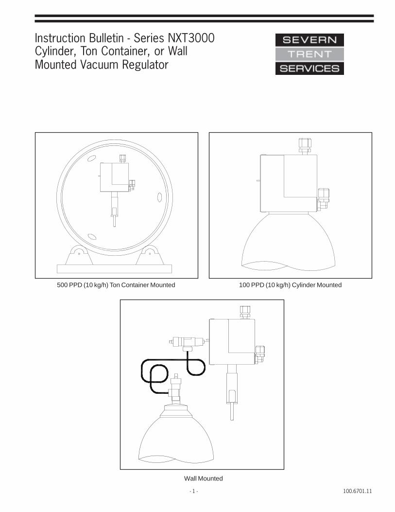
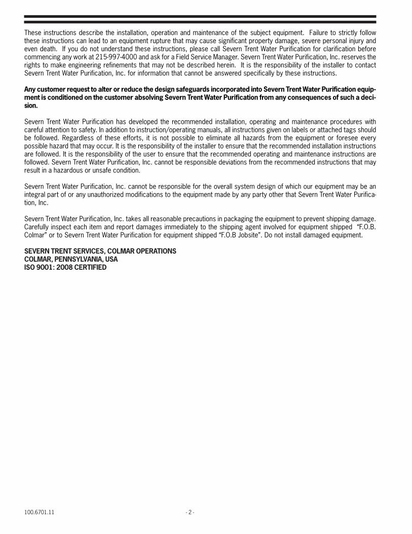
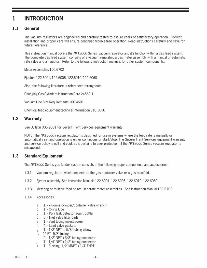
Instruction Bulletin - Series NXT3000Cylinder, Ton Container, or WallMounted Vacuum Regulator
100 PPD (10 kg/h) Cylinder Mounted500 PPD (10 kg/h) Ton Container Mounted
Wall Mounted
100.6701.11 - 2 -
These instructions describe the installation, operation and maintenance of the subject equipment. Failure to strictly followthese instructions can lead to an equipment rupture that may cause significant property damage, severe personal injury andeven death. If you do not understand these instructions, please call Severn Trent Water Purification for clarification beforecommencing any work at 215-997-4000 and ask for a Field Service Manager. Severn Trent Water Purification, Inc. reserves therights to make engineering refinements that may not be described herein. It is the responsibility of the installer to contactSevern Trent Water Purification, Inc. for information that cannot be answered specifically by these instructions.
Any customer request to alter or reduce the design safeguards incorporated into Severn Trent Water Purification equip-ment is conditioned on the customer absolving Severn Trent Water Purification from any consequences of such a deci-sion.
Severn Trent Water Purification has developed the recommended installation, operating and maintenance procedures withcareful attention to safety. In addition to instruction/operating manuals, all instructions given on labels or attached tags shouldbe followed. Regardless of these efforts, it is not possible to eliminate all hazards from the equipment or foresee everypossible hazard that may occur. It is the responsibility of the installer to ensure that the recommended installation instructionsare followed. It is the responsibility of the user to ensure that the recommended operating and maintenance instructions arefollowed. Severn Trent Water Purification, Inc. cannot be responsible deviations from the recommended instructions that mayresult in a hazardous or unsafe condition.
Severn Trent Water Purification, Inc. cannot be responsible for the overall system design of which our equipment may be anintegral part of or any unauthorized modifications to the equipment made by any party other that Severn Trent Water Purifica-tion, Inc.
Severn Trent Water Purification, Inc. takes all reasonable precautions in packaging the equipment to prevent shipping damage.Carefully inspect each item and report damages immediately to the shipping agent involved for equipment shipped “F.O.B.Colmar” or to Severn Trent Water Purification for equipment shipped “F.O.B Jobsite”. Do not install damaged equipment.
SEVERN TRENT SERVICES, COLMAR OPERATIONSCOLMAR, PENNSYLVANIA, USAISO 9001: 2008 CERTIFIED

- 3 - 100.6701.11
Table of Contents1 INTRODUCTION . . . . . . . . . . . . . . . . . . . . . . . . . . . . . . . . . . . . . . . . . . . . . . . . . . . . . . . . . . . . . . . . . . 4
1.1 General . . . . . . . . . . . . . . . . . . . . . . . . . . . . . . . . . . . . . . . . . . . . . . . . . . . . . . . . . . . . . . . . . . . . . . . . 41.2 Warranty . . . . . . . . . . . . . . . . . . . . . . . . . . . . . . . . . . . . . . . . . . . . . . . . . . . . . . . . . . . . . . . . . . . . . . . . 41.3 Standard Equipment . . . . . . . . . . . . . . . . . . . . . . . . . . . . . . . . . . . . . . . . . . . . . . . . . . . . . . . . . . . . . . . . 41.4 Specifications . . . . . . . . . . . . . . . . . . . . . . . . . . . . . . . . . . . . . . . . . . . . . . . . . . . . . . . . . . . . . . . . . . . . 5
2 OPERATION. . . . . . . . . . . . . . . . . . . . . . . . . . . . . . . . . . . . . . . . . . . . . . . . . . . . . . . . . . . . . . . . . . . . . 62.1 General . . . . . . . . . . . . . . . . . . . . . . . . . . . . . . . . . . . . . . . . . . . . . . . . . . . . . . . . . . . . . . . . . . . . . . . . 62.2 Safety Features . . . . . . . . . . . . . . . . . . . . . . . . . . . . . . . . . . . . . . . . . . . . . . . . . . . . . . . . . . . . . . . . . . . 62.3 Principles of Operation . . . . . . . . . . . . . . . . . . . . . . . . . . . . . . . . . . . . . . . . . . . . . . . . . . . . . . . . . . . . . 72.4 Capacity . . . . . . . . . . . . . . . . . . . . . . . . . . . . . . . . . . . . . . . . . . . . . . . . . . . . . . . . . . . . . . . . . . . . . . . . 72.5 Typical Gas Feed Systems . . . . . . . . . . . . . . . . . . . . . . . . . . . . . . . . . . . . . . . . . . . . . . . . . . . . . . . . . . . 7
3 INSTALLATION . . . . . . . . . . . . . . . . . . . . . . . . . . . . . . . . . . . . . . . . . . . . . . . . . . . . . . . . . . . . . . . . . . . 94 OPERATING INSTRUCTIONS . . . . . . . . . . . . . . . . . . . . . . . . . . . . . . . . . . . . . . . . . . . . . . . . . . . . . . . . 19
4.1 Initial Start-Up . . . . . . . . . . . . . . . . . . . . . . . . . . . . . . . . . . . . . . . . . . . . . . . . . . . . . . . . . . . . . . . . . . . 194.2 Operation . . . . . . . . . . . . . . . . . . . . . . . . . . . . . . . . . . . . . . . . . . . . . . . . . . . . . . . . . . . . . . . . . . . . . . 23
5 SHUTDOWN. . . . . . . . . . . . . . . . . . . . . . . . . . . . . . . . . . . . . . . . . . . . . . . . . . . . . . . . . . . . . . . . . . . . 285.0 Shutdown for Servicing . . . . . . . . . . . . . . . . . . . . . . . . . . . . . . . . . . . . . . . . . . . . . . . . . . . . . . . . . . . . 285.1 Shutdown for Extended Period . . . . . . . . . . . . . . . . . . . . . . . . . . . . . . . . . . . . . . . . . . . . . . . . . . . . . . . 28
6 SERVICE . . . . . . . . . . . . . . . . . . . . . . . . . . . . . . . . . . . . . . . . . . . . . . . . . . . . . . . . . . . . . . . . . . . . . . 296.1 General . . . . . . . . . . . . . . . . . . . . . . . . . . . . . . . . . . . . . . . . . . . . . . . . . . . . . . . . . . . . . . . . . . . . . . . 296.2 Cleaning Agents . . . . . . . . . . . . . . . . . . . . . . . . . . . . . . . . . . . . . . . . . . . . . . . . . . . . . . . . . . . . . . . . . . 306.3 Lubricating Agents . . . . . . . . . . . . . . . . . . . . . . . . . . . . . . . . . . . . . . . . . . . . . . . . . . . . . . . . . . . . . . . . 306.4 O-Ring . . . . . . . . . . . . . . . . . . . . . . . . . . . . . . . . . . . . . . . . . . . . . . . . . . . . . . . . . . . . . . . . . . . . . . . 306.5 Diaphragms . . . . . . . . . . . . . . . . . . . . . . . . . . . . . . . . . . . . . . . . . . . . . . . . . . . . . . . . . . . . . . . . . . . . 306.6 Check Valves . . . . . . . . . . . . . . . . . . . . . . . . . . . . . . . . . . . . . . . . . . . . . . . . . . . . . . . . . . . . . . . . . . . 306.7 Hose Lines . . . . . . . . . . . . . . . . . . . . . . . . . . . . . . . . . . . . . . . . . . . . . . . . . . . . . . . . . . . . . . . . . . . . . 306.8 Tubing Replacement . . . . . . . . . . . . . . . . . . . . . . . . . . . . . . . . . . . . . . . . . . . . . . . . . . . . . . . . . . . . . . . 306.9 Inlet Valve . . . . . . . . . . . . . . . . . . . . . . . . . . . . . . . . . . . . . . . . . . . . . . . . . . . . . . . . . . . . . . . . . . . . . . 306.10 Manifold . . . . . . . . . . . . . . . . . . . . . . . . . . . . . . . . . . . . . . . . . . . . . . . . . . . . . . . . . . . . . . . . . . . . . . . 30
7 TROUBLESHOOTING CHART . . . . . . . . . . . . . . . . . . . . . . . . . . . . . . . . . . . . . . . . . . . . . . . . . . . . . . . . 31
8 APPENDIX . . . . . . . . . . . . . . . . . . . . . . . . . . . . . . . . . . . . . . . . . . . . . . . . . . . . . . . . . . . . . . . . . . . . . 34Vacuum Lines - Limits of Extension . . . . . . . . . . . . . . . . . . . . . . . . . . . . . . . . . . . . . . . . . . . . . . . . . . . . . . . . . 35Figure 11 Pictorial Representation of the Reference Distances Plotted in Figure 12 through 14. . . . . . . . . . . . . 35Figure 12 Vacuum Line(s) Limits of Extension vs. Maximum System Capacity for Chlorine Gas
Dispensing System . . . . . . . . . . . . . . . . . . . . . . . . . . . . . . . . . . . . . . . . . . . . . . . . . . . . . . . . . . . 37Figure 13 Vacuum Line(s) Limits of Extension vs. Maximum System Capacity for Sulfur Dioxide
Dispensing System . . . . . . . . . . . . . . . . . . . . . . . . . . . . . . . . . . . . . . . . . . . . . . . . . . . . . . . . . . . 38Figure 14 Vacuum Line(s) Limits of Extension vs. Maximum System Capacity for Ammonia
Dispensing System . . . . . . . . . . . . . . . . . . . . . . . . . . . . . . . . . . . . . . . . . . . . . . . . . . . . . . . . . . . 39
FIGURES1 Basic System Schematics . . . . . . . . . . . . . . . . . . . . . . . . . . . . . . . . . . . . . . . . . . . . . . . . . . . . . . . . . . . 82 Cylinder Mounted Vacuum Regulators . . . . . . . . . . . . . . . . . . . . . . . . . . . . . . . . . . . . . . . . . . . . . . . . . . 103 Ton Container and Wall Mounted Vacuum Regulators . . . . . . . . . . . . . . . . . . . . . . . . . . . . . . . . . . . . . . . . 114 Mounting Cylinder Mounted Vacuum Regulators. . . . . . . . . . . . . . . . . . . . . . . . . . . . . . . . . . . . . . . . . . . . 125 Mounting Ton Container Mounted Vacuum Regulators . . . . . . . . . . . . . . . . . . . . . . . . . . . . . . . . . . . . . . . 126 Mounting Wall Mounted Vacuum Regulators . . . . . . . . . . . . . . . . . . . . . . . . . . . . . . . . . . . . . . . . . . . . . . 137 Connections - Wall Mounted Vacuum Regulators . . . . . . . . . . . . . . . . . . . . . . . . . . . . . . . . . . . . . . . . . . . 148 Out-of-Gas Alarm Switch . . . . . . . . . . . . . . . . . . . . . . . . . . . . . . . . . . . . . . . . . . . . . . . . . . . . . . . . . . . . 159 SO2 Cylinder Adaptor Plate . . . . . . . . . . . . . . . . . . . . . . . . . . . . . . . . . . . . . . . . . . . . . . . . . . . . . . . . . 1510 Wall Mounted Vacuum Switches . . . . . . . . . . . . . . . . . . . . . . . . . . . . . . . . . . . . . . . . . . . . . . . . . . . . . . 1611 Vacuum Regulator Exploded View . . . . . . . . . . . . . . . . . . . . . . . . . . . . . . . . . . . . . . . . . . . . . . . . . . . . . 1712 Meter Exploded View . . . . . . . . . . . . . . . . . . . . . . . . . . . . . . . . . . . . . . . . . . . . . . . . . . . . . . . . . . . . . . 18
100.6701.11 - 4 -
1 INTRODUCTION
1.1 General
The vacuum regulators are engineered and carefully tested to assure years of satisfactory operation. Correctinstallation and proper care will ensure continued trouble free operation. Read instructions carefully and save forfuture reference.
This instruction manual covers the NXT3000 Series vacuum regulator and it's function within a gas feed system.The complete gas feed system consists of a vacuum regulator, a gas meter assembly with a manual or automaticrate valve and an ejector. Refer to the following instruction manuals for other system components:
Meter Assemblies 100.6702
Ejectors 122.6001, 122.6006, 122.6010, 122.6060
Also, the following literature is referenced throughout:
Changing Gas Cylinders Instruction Card 24563.1
Vacuum Line Size Requirements 100.4601
Chemical feed equipment technical information 010.3650
1.2 Warranty
See Bulletin 005.9001 for Severn Trent Services equipment warranty.
NOTE: The NXT3000 vacuum regulator is designed for use in systems where the feed rate is manually orautomatically set and operation is either continuous or start/stop. The Severn Trent Services equipment warrantyand service policy is null and void, as it pertains to user protection, if the NXT3000 Series vacuum regulator ismisapplied.
1.3 Standard Equipment
The NXT3000 Series gas feeder system consists of the following major components and accessories:
1.3.1 Vacuum regulator, which connects to the gas container valve or a gas manifold.
1.3.2 Ejector assembly. See Instruction Manuals 122.6001, 122.6006, 122.6010, 122.6060.
1.3.3 Metering or multiple feed points, separate meter assemblies. See Instruction Manual 100.6702.
1.3.4 Accessories
a. (1) - chlorine cylinder/container valve wrench.b. (1) - O-ring lubec. (1) - Poly leak detector squirt bottled. (6) - Inlet valve filter padse. (1) - Vent tubing insect screenf. (4) - Lead valve gasketsg. (1) - 1/2" NPT to 5/8" tubing elbowh. 25 FT - 5/8" tubingi. (2) - 1/2" NPT x 3/8" tubing connectorj. (1) - 1/4" NPT x 1/2" tubing connectork. (1) - Bushing, 1/2" MNPT x 1/4" FNPT

- 5 - 100.6701.11
NOTE: This instruction manual covers the vacuum regulator only. Since the vacuum regulator is one partof a gas feed system, references will be made within this bulletin to meter assemblies, ejectors andother ancillary equipment that complete the various systems. Installation of a complete systemis covered within.
1.4 Specifications
Capacity: Chlorine - 1 to 500 PPD (20 g/h to 6 g/h)
Sulfur Dioxide - 1 to 500 PPD (20g/h to 10 g/h)
Ammonia - 5 to 250 PPD (30 g/h to 5 g/h)
Carbon Dioxide - 0.75 to 375 PPD (15 g/h to 7 kg/h)
The maximum delivery capacity is dependent upon the mounting location of the vacuum regulator and theambient temperature. These capacities are listed in Table A for an ambient temperature of 70°Fto 5°F.
deldnaHgnieBsaGnoitacoLgnitnuoMrotalugeRmuucaV
llaW reniatnoCnoT rednilyC
edixoiDrufluSroenirolhC d/bl005h/gk01
d/bl005h/gk01
d/bl001h/gk2
ainommA d/bl052h/gk5 AN AN
*edixoiDnobraC d/bl573h/gk7 AN AN
*Due to the high gas pressure in the carbon dioxide storage cylinders, a two stage pressure regulator isrequired between the gas source and the vacuum regulator.
Temperature limits: 35° to 130°F (2° to 54°C)
Maximum inlet pressure: 300 PSIG
Manifold heater power: 25 Watt, 120 or 240 VAC, 50/60 Hz
100.6701.11 - 6 -
2 OPERATION
2.1 General
A. Vacuum Regulator
The vacuum regulator serves to reduce the supply pressure in a gas cylinder or ton container to a regulatedvacuum for safe transport of the gas to the point of application. A leak in any portion of the vacuum transportline simply allows air to be pulled into the system. A substantial vacuum line break will stop gas feed fromtaking place. The vacuum regulator is a spring opposed diaphragm type that resumes vacuum to operate thegas inlet valve. The vacuum regulator can control gas flow rates from 1 to 500PPD without any componentchanges.
For manually controlled systems, the flow rate of gas through the regulator is set and indicated by a meterassembly which contains a manually adjusted needle valve, called a rate valve. One or more meterassemblies may be furnished with each vacuum regulator and they may be either integrally mounted on thevacuum regulator or wall mounted, as required. The operating vacuum that pulls the gas through the systemis created by a separately mounted ejector, one normally being required for each meter assembly.
Each vacuum regulator is equipped with a vacuum actuated, manually reset, three position, “status” levermarked RESERVE, OPERATING, and EMPTY. When a system is placed into operation, the lever is manually setto the operating position. When the gas in the cylinder or ton container is exhausted, or has beeninadvertently interrupted, the lever automatically moves to the EMPTY position. The RESERVE position is usedwhen a dual regulator type gas dispensing system is furnished, The RESERVE position indicates that the gascylinder is full and is in stand-by condition. When the operating tank is exhausted, its status lever moves toEMPTY and the reserve tank status lever moves to the OPERATING position. This provides an automaticchangeover of gas feed from the exhausted to the full gas supply container.
B. Meter-Rate Valve Assembly
The meter assembly is a variable area type meter and provides visual indication of the gas flow rate set bythe rate valve.
The rate valve is located at the meter outlet (top) to provide manual selection of the desired gas flow rate.
The capacity range of each meter-rate valve assembly is clearly indicated by a calibrated scale, directreading in pounds per day (lb/d) and grams per hour (g/h) or kilograms per hour (kg/h), etched on themeter assembly tube.
For systems requiring automatic feed control, an automatic valve is provided to be piped between theejector and the meter assembly. The manual valve on the meter assembly is not supplied for this mode ofoperation.
C. Ejector
The ejector, operated by the flow of water or process liquid under sufficient pressure and velocity, createsthe necessary vacuum to operate the regulator. In some instances, a booster pump is required to providesufficient water pressure and flow rate.
2.2 Safety Features
The gas inlet valve of the vacuum regulator provides positive shut-off in the absence of operating vacuum.Therefore, the regulator is sealed off from the gas supply if a major leak should develop in the vacuum portion ofthe gas dispensing system during normal operation or at shutdown when the water supply to the ejector is shut off.This valve is protected by a mesh type filter located within the gas inlet connection.
A pressure relief valve, within the vacuum regulator, provides for venting gas, through a vent connection, to aremote and suitable location should gas at greater than atmospheric pressure enter the regulator. This abnormalcondition could occur as liquid chemical enters the regulator; or, the gas inlet valve of the regulator does notclose tightly due to the accumulation of foreign matter not removed by the filter.
- 7 - 100.6701.11
The manifold assembly, supplied with wall and ton container mounted regulators, has a liquid chemical trap, anwrap-around type heater and a cartridge type filter. The trap catches any condensed gas vapors (liquid chemical)which may form in the gas supply line of a wall mounted unit or the small volume of liquid chemical dischargedthrough the gas valve of a ton container each time a new container is placed in service to prevent its entranceinto the regulator. The heater vaporizes any liquid chemical and prevents any gas from condensing in themanifold, thereby permitting only gas to enter the regulator. The filter cartridge serves to remove entrainedforeign particles from the gas entering the manifold assembly, thereby reducing the solids loading on the meshtype filter located in the gas inlet connection of the regulator.
2.3 Principle of OperationWhen the ejector is operating, gas enters the regulator, being reduced from supply pressure to a constantlyregulated vacuum by the throttling action of the regulator, the meter assembly rate valve assembly and into theejector. Within the ejector, the gas is thoroughly mixed with the water or process liquid to form a chemicalsolution which is delivered via solution hose or piping to the point of application.
WARNINGAll components of the gas dispensing system are constructed of materialscapable of withstanding the corrosive action of the particular gas for which
the system has been specified. Never attempt to use any componentfor handling a gas different from that for which it has been purchased.
Failure to observe this warning can result in equipment failure and bodily injury.
2.4 CapacityEach vacuum regulator has the maximum feeding capacity of 500PPD of chlorine. The actual system maximum isdetermined by the flowmeter-rate valve combination and the commensurate ejector sizing. The capacity of aninstalled system may be changed by changing the meter assembly and/or ejector capacity components. Refer tothe meter assembly parts list, 100.7602 and ejector parts lists, Section 122 for the specific part numbersassociated with each ejector.
2.5 Typical Gas Feed SystemsFigure 1 illustrates several basic system arrangements. The meter-rate valve assembly may be mounted directlyon the vacuum regulator or remotely on a wall. The meter assemblies have the ability of being ganged with theactual total gas flowrate limited by the 500PPD capacity of the vacuum regulator for up to five separate feedpoints. A mix of automatic and manual feed points are also possible as the gas feed processes dictate.
Automatic switchover may be achieved by adding a second vacuum regulator and connecting the outlets to a teeconnected to the meter assemblies and following the procedures outlined further in this manual.

100.6701.11 - 8 -
Figure 1 - Basic System Schematics
- 9 - 100.6701.11
3 INSTALLATION
Select a location which can be isolated from unauthorized personnel. Outdoor installations for cylinder or toncontainer mounted regulators are permissible provided that the ambient temperature will not fall below 35°F (2°C)for chlorine and ammonia systems; or, 40°F (5°C) for sulfur dioxide systems. Outdoor installations for wallmounted regulators are not recommended (especially if the gas supply system consists of two or more containers)since a sudden decrease in ambient temperature will result in the formation of condensed gas vapors (liquidchemical) in the gas supply line. This liquid will be swept into the manifold and if sufficient in volume to exceed thevaporizing capacity of the manifold heater, will flood the manifold and enter the regulator.
CAUTIONThe corrosion resistant plastics used in the construction of all
regulators and meter-rate valve assemblies, regardless of the particulargas service for which they have been supplied, will soften and distort
above 130°F (54°C). Therefore, the ambient temperature, in every instance,must never exceed this maximum allowable limit.
For outdoor installations, select an area which will provide natural protection for the gas supply against directsunlight. If this is not possible, erect an open type structure to provide this protection. Observe the upper and lowertemperature limits.
For indoor installations, select a well ventilated enclosure provided with a source of heat, if necessary, to maintain,a comfortable ambient temperature. Additionally, the enclosure should be of sufficient size to permit easy accessfor inspection and maintenance of the regulator and gas supply. And finally, to provide for maximum safety ofoperating personnel, the enclosure should be equipped and fitted as described under the Personnel Safety Section ofInstruction Bulletin 010.3550.
The relative locations of the regulator(s); the remote mounted meter-rate valve assemblies, if used; and the ejector(s)must be chosen so that the length(s) of the vacuum line(s) does not exceed the value(s) shown in the appendix.Maximum gas flow to the point(s) of application will not be achieved if these limits are exceeded. Therefore, it willbe necessary to refer to the appendix before locating the components of the system to verify that the length of eachinterconnecting vacuum line (and vent line) when the regulator is mounted on a cylinder valve or the gas valve of a toncontainer to permit easy transfer of the regulator from one cylinder or container to another. Arrange all vacuum linesto prevent crimping.
The vent line(s), one required for each regulator, must be extended to a suitable area (outside the building for indoorinstallations) where gas fumes cannot cause damage or endanger personnel. Although there is no restriction (withinpractical limits) to the distance over which the vent line(s) can be extended, each line, if applicable, must be runindividually. Multiple vent lines cannot be manifolded. The vent line must slope downward from the vacuum regulatorto provide a positive drain, preventing accumulation of any moisture in the vent line. The end of the vent line(s) mustbe turned downward to prevent the entrance of water. The fine mesh plastic screen(s) (supplied in the accessorypackage) must be installed over the outlet(s) to prevent insects from entering the line(s).
When extending vent lines, eliminate low spots to prevent trapping condensed water vapor and arrange to preventcrimping.
All threaded plastic-to-plastic pipe joints must be lubricated to prevent galling of the threads, provide a perfect sealand to permit ease of disassembly. The recommended lubricating agent is Teflon (self lubricating) tape. Apply tapeto the male pipe threads, one thread from the end, only to prevent it from entering the piping. Exercise care not toovertighten the joints as this may crack the plastic. Slightly more than hand tight is usually sufficient.
The vacuum regulator can be direct mounted to a 150 lb cylinder, ton, container wall mounted or mounted on a multi-container manifold.
Cylinder Mounting refer to Figure 4.
Ton Container Mounting refer to Figure 5.
Wall Mounting refer to Figure 6.
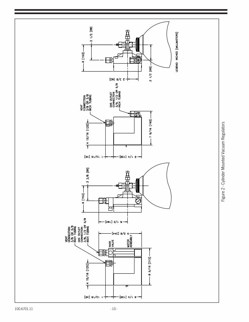
100.6701.11 - 10 -
Figu
re 2
- Cy
linde
r Mou
nted
Vac
uum
Reg
ulat
ors

- 11 - 100.6701.11
Figu
re 3
- To
n Co
ntai
ner a
nd W
all M
ount
ed V
acuu
m R
egul
ator
s
WIT
H IN
TEG
RAL
LY M
OU
NTE
D M
ETER
RAT
E VA
LVE
ASSE
MBL
YW
ITH
OU
T IN
TEG
RAL
LY M
OU
NTE
D M
ETER
RAT
E VA
LVE
ASSE
MBL
Y
100.6701.11 - 12 -
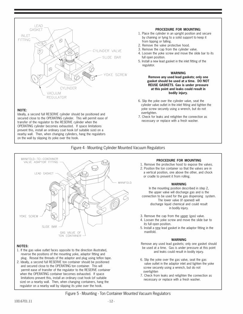
Figure 4 - Mounting Cylinder Mounted Vacuum Regulators
Figure 5 - Mounting - Ton Container Mounted Vacuum Regulators
NOTE:Ideally, a second full RESERVE cylinder should be positioned andsecured close to the OPERATING cylinder. This will permit ease oftransfer of the regulator to the RESERVE cylinder when theOPERATING cylinder becomes exhausted. If space limitationsprevent this, install an ordinary coat hook (of suitable size) on anearby wall. Then, when changing cylinders, hang the regulatorson the wall by slipping its yoke over the hook.
PROCEDURE FOR MOUNTING:1. Place the cylinder in an upright position and secure by chaining or tying to a solid support to keep it from tipping or falling.2. Remove the valve protective hood.3. Remove the cap from the cylinder valve.4. Loosen the yoke screw and move the slide bar to its full open position.5. Install a new lead gasket in the inlet fitting of the regulator.
WARNINGRemove any used lead gaskets; only one
gasket should be used at a time. DO NOTREUSE GASKETS. Gas is under pressure
at this point and leaks could result inbodily injury.
6. Slip the yoke over the cylinder valve, seat the cylinder valve outlet in the inlet fitting and tighten the yoke screw securely using a wrench, but do not overtighten.7. Check for leaks and retighten the connection as necessary or replace with a fresh washer.
PROCEDURE FOR MOUNTING1. Remove the protective hood to expose the valves.2. Position the ton container so that the valves are in a vertical position, one above the other, and chock or cradle to prevent it from rolling.
WARNINGIn the mounting position described in step 2,the upper valve will discharge gas and is the
connection to be used for the gas dispensing system.The lower valve (if opened) will
discharge liquid chemical and could resultin bodily injury.
3. Remove the cap from the upper (gas) valve.4. Loosen the yoke screw and move the slide bar to its full open position.5. Install a new lead gasket in the adaptor fitting in the manifold.
WARNINGRemove any used lead gaskets; only one gasket shouldbe used at a time. Gas is under pressure at this point
and leaks could result in bodily injury.
6. Slip the yoke over the gas valve, seat the gas valve outlet in the adaptor inlet and tighten the yoke screw securely using a wrench, but do not overtighten7. Check from leaks and retighten the connection as necessary or replace with a fresh washer.
NOTES:1. If the gas valve outlet faces opposite to the direction illustrated, reverse the positions of the mounting yoke, adaptor fitting and plug. Reseal the threads of the adaptor and plug using teflon tape.2. Ideally, a second full RESERVE ton container should be positioned and secured close to the OPERATING ton container. This will permit ease of transfer of the regulator to the RESERVE container when the OPERATING container becomes exhausted. If space limitations prevent this, install an ordinary coat hook (of suitable size) on a nearby wall. Then, when changing containers, hang the regulator on a nearby wall by slipping its yoke over the hook.

- 13 - 100.6701.11
Figure 6 - Mounting - Wall Mounted Vacuum Regulators
GENERALOne of the gas inlet connection is fitted with a plug. Theplug can be removed and installed in the opposite side if it isnot convenient (when mounting on a wall) or possible(when mounting on the gas valve of a ton container) to usethe open connection as supplied. If the plug is relocated,reseal the threads using teflon tape.
1. Mount vertically plumb on a wall (or other suitable surface) at a convenient height for setting the rate valve and reading the flowmeter if integrally mounted.2. Provide four threaded openings to accept 1/4 - 20 hex head cap screws. Slip a washer over each screw and install the screws through the 5/16" wide mounting slots in the manifold.3. Connect the gas supply to the manifold as illustrated and described in Figure 7.
100.6701.11 - 14 -
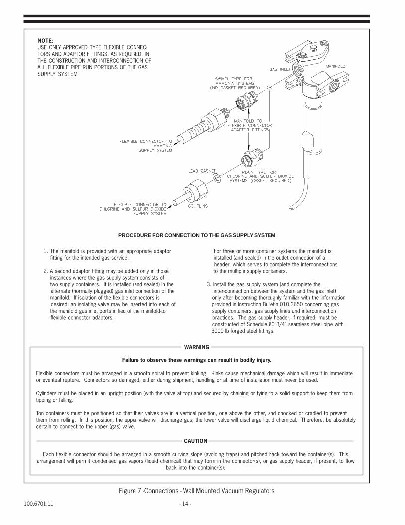
Figure 7 -Connections - Wall Mounted Vacuum Regulators
NOTE:USE ONLY APPROVED TYPE FLEXIBLE CONNEC-TORS AND ADAPTOR FITTINGS, AS REQUIRED, INTHE CONSTRUCTION AND INTERCONNECTION OFALL FLEXIBLE PIPE RUN PORTIONS OF THE GASSUPPLY SYSTEM
1. The manifold is provided with an appropriate adaptor fitting for the intended gas service.
2. A second adaptor fitting may be added only in those instances where the gas supply system consists of two supply containers. It is installed (and sealed) in the alternate (normally plugged) gas inlet connection of the manifold. If isolation of the flexible connectors is desired, an isolating valve may be inserted into each of the manifold gas inlet ports in lieu of the manifold-to -flexible connector adaptors.
PROCEDURE FOR CONNECTION TO THE GAS SUPPLY SYSTEM
For three or more container systems the manifold is installed (and sealed) in the outlet connection of a header, which serves to complete the interconnections to the multiple supply containers.
3. Install the gas supply system (and complete the inter-connection between the system and the gas inlet) only after becoming thoroughly familiar with the information provided in Instruction Bulletin 010.3650 concerning gas supply containers, gas supply lines and interconnection practices. The gas supply header, if required, must be constructed of Schedule 80 3/4" seamless steel pipe with 3000 lb forged steel fittings.
Flexible connectors must be arranged in a smooth spiral to prevent kinking. Kinks cause mechanical damage which will result in immediateor eventual rupture. Connectors so damaged, either during shipment, handling or at time of installation must never be used.
Cylinders must be placed in an upright position (with the valve at top) and secured by chaining or tying to a solid support to keep them fromtipping or falling.
Ton containers must be positioned so that their valves are in a vertical position, one above the other, and chocked or cradled to preventthem from rolling. In this position, the upper valve will discharge gas; the lower valve will discharge liquid chemical. Therefore, be absolutelycertain to connect to the upper (gas) valve.
CAUTION
Each flexible connector should be arranged in a smooth curving slope (avoiding traps) and pitched back toward the container(s). Thisarrangement will permit condensed gas vapors (liquid chemical) that may form in the connector(s), or gas supply header, if present, to flow
back into the container(s).
WARNING
Failure to observe these warnings can result in bodily injury.

- 15 - 100.6701.11
Figure 8 - Out-of-Gas Alarm Switch
Figure 9 - SO2 Cylinder Adaptor Plate
An optional, field mountable, switch is available for remote indication of a loss of gas supply. The switch may beattached directly to the vacuum regulator body without disassembling the body. Refer to Instruction Bulletin100.6703and parts list 100.7603 for further details. The kit P/N is 674B093U02
SCREWSCREW
ADAPTOR PLATE
STUD
STUD
GASKET
GASKET
GASKET
REGULATORVACUUM
VALVECYLINDER
CYLINDER
100.6701.11 - 16 -
Accessories:
Manifold Adaptor Kits: Manifold adaptor kits are available to convert the cylinder mounted vacuum regulator to either toncontainer or wall mounting.
Wall mounting kit P/N 19558
Ton container mounting kit P/N 19560
Refer to parts list 100.7606 for detailed parts listing.
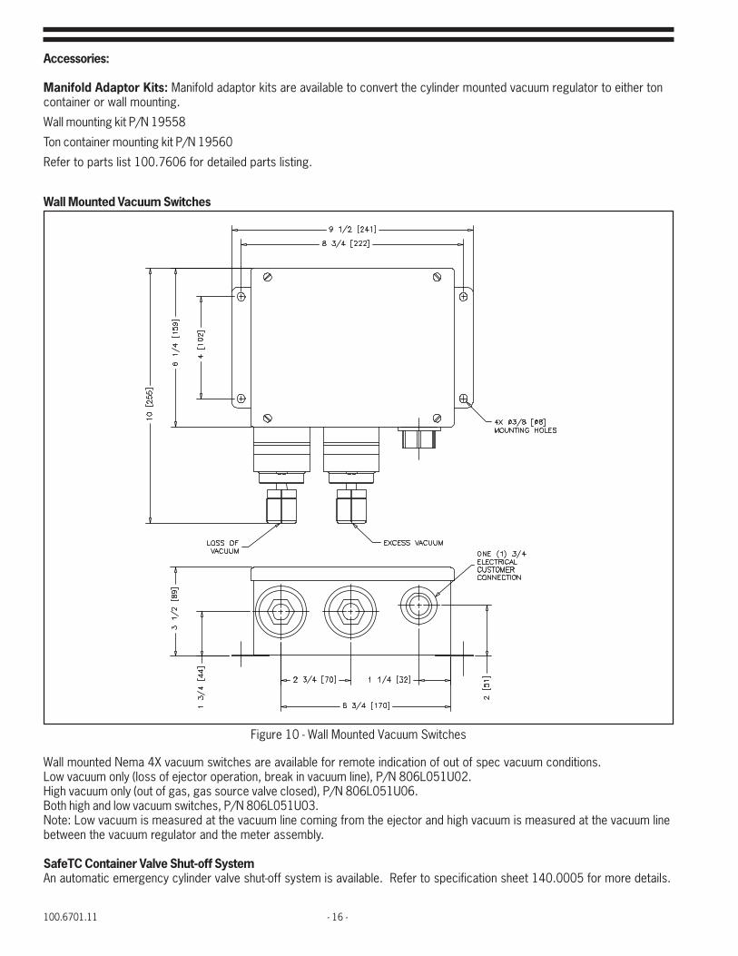
Wall Mounted Vacuum Switches
Wall mounted Nema 4X vacuum switches are available for remote indication of out of spec vacuum conditions.Low vacuum only (loss of ejector operation, break in vacuum line), P/N 806L051U02.High vacuum only (out of gas, gas source valve closed), P/N 806L051U06.Both high and low vacuum switches, P/N 806L051U03.Note: Low vacuum is measured at the vacuum line coming from the ejector and high vacuum is measured at the vacuum linebetween the vacuum regulator and the meter assembly.
SafeTC Container Valve Shut-off SystemAn automatic emergency cylinder valve shut-off system is available. Refer to specification sheet 140.0005 for more details.
Figure 10 - Wall Mounted Vacuum Switches
- 17 - 100.6701.11
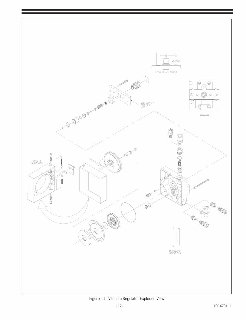
Figure 11 - Vacuum Regulator Exploded View
100.6701.11 - 18 -
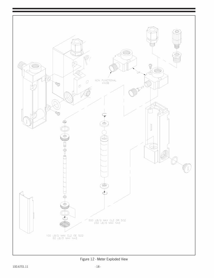
Figure 12 - Meter Exploded View
- 19 - 100.6701.11
4 OPERATING INSTRUCTIONS
4.1 Initial Start-Up
Prior to start-up after an extended shutdown, inspect all lines and connections, making replacements as neces-sary. If lines are transparent, inspect for blockage. Disconnect any blocked line and clean by blowing down. Iflines cannot be visually inspected, disconnect the lines and blow down to make certain no blockage exists. DONOT PRESSURE TEST THE VACUUM LINES AS EQUIPMENT DAMAGE WILL RESULT.
A. Checking for Operating Vacuum
1. Remove the vent valve spring and flapper located on the top of the vacuum regulator.
If the gas dispensing system is of the dual regulator type, perform this action on the furthest remotemounted regulator since one of the purposes of this procedure is to establish that the length of thevacuum line(s) do not exceed the maximum allowable transport distance.
2. Move the “status” lever located on the side of the regulator to its OPERATING position. Be sure thatthe valve on the gas container is closed during this procedure.
If the gas dispensing system is of the dual regulator type, perform this action on both regulators sinceanother purpose of this procedure is to establish that the connection(s) to or throughout the gas supplysystem(s) have been properly made and secured.
3. Open any shut-off valves in the chemical solution line between each ejector and its point of application.
4. Open the shut-off valve in the water supply line to each ejector and start up the booster pump(s), ifused.
5. Gradually open the rate valve of each meter-rate valve assembly while observing the upwardmovement of the meter assembly float. On systems with an automatic valve, manually operate thevalve while observing the meter assembly float.
The gas dispensing system is now operating on air being drawn through the vent. Sufficient ejectoroperating vacuum to provide maximum operating capacity for the complete system is verified wheneach meter-valve assembly can be operated simultaneously on air at approximately;a) 50% or higher of max-scale position for chlorine and sulfur dioxide systems; and, b) 25% or higherof max-scale position for ammonia systems.
If the meter assembly float does not rise or if the required air flow rate is not achieved in eachassembly the first time, the gas dispensing system is placed in operation, refer to Trouble “A” in thetroubleshooting chart to determine the probable cause(s) and corrective action(s) to be taken. If eitherof these conditions occur on subsequent start-ups (e.g.: following an extended period of servicingshutdown), refer to Trouble “B” in the troubleshooting chart to determine the probable cause(s) andcorrective action(s) to be taken.
6. Replace the vent valve spring and flapper, sparingly lubricate the threads (if necessary) to provide aperfect seal. Do not apply any lubricants to the seat seal o-ring or the vent valve seat.
7. With the system dead-ended; a) the float of each meter-rate valve assembly should fall to zero, andb) the “status” lever located on the side of the regulator(s) should move to the EMPTY position (theclosed valve shows the same response as an empty gas container).
If either of these conditions do not occur, check that the connection(s) to or throughout the gas supplysystem, associated with the regulator(s) failing to exhibit the proper response, have been properlymade as described and illustrated in Figures 4,5, or 7.
If the occurrence of these conditions cannot be traced to a faulty connection, refer to Trouble "C" orTrouble "D". Trouble "C" in the troubleshooting chart can determine other probable cause(s) andcorrective action(s) to be taken if this is placed in operation. Trouble "D" in the troubleshooting chartcan determine other probable cause(s) and corrective action(s) to be taken on subsequent start-ups(e.g.: following an extended period or servicing shutdown).
8. When the system exhibits the requirements set forth in steps 5 and 7, shut off the water supply to theejector(s).

100.6701.11 - 20 -
B. Checking for Gas Leaks
1. GeneralThe test solution to be used in each of the following procedures is dependent upon the gas beinghandled. Use a 26°Baume' (ammonium hydroxide, aqua ammonia) ammonia solution for chlorine and sulfurdioxide systems and a 10% hydrochloric (muriatic) acid solution for ammonia systems.
NOTE: Household ammonia is not strong enough to serve as a test solution.
If the gas dispensing system is of the dual regulator type, be certain to perform the “Checking for GasLeaks” procedure(s), as applicable, and independently, on each of the associated gas supply systems inquestion.
WARNINGDuring the performance of the “Checking for Gas Leaks” procedure(s),
as applicable, be certain to use plastic or rubber gloves to protectthe hands against direct contact with the test solution. Avoid
breathing fumes emitted from the test solution and the smoke formed(as a result of the chemical reaction which occurs between the fumesof the test solution and the gas in question) in the immediate vicinity
of a leak as it may irritate the throat.
The gas inlet valve is functional when the “status” lever located on the side of the regulator is in its EMPTYposition. The lever automatically assumes this position during the occurrence of a high vacuum conditionwithin the regulator. For example, when the system is dead-ended at the conclusion of the “checking foroperation vacuum” procedure; or, when the supply of gas becomes exhausted during the course of normaloperation. Therefore, it is not necessary to move the lever to its operating position prior to, or during,the performance of the “Checking for Gas Leaks” procedure(s). In fact, it will be impossible to do sofollowing the “Checking for Gas Leaks” procedure, at which time the lever becomes “vacuum locked” inits EMPTY position and will remain so until gas pressure is applied to the gas inlet connection of theregulator; i.e., either during or at the conclusion of the performance of each of the followingprocedures.
2. Cylinder Mounted Vacuum Regulatorsa. Fill the plastic squirt bottle, supplied in the accessory kit, approximately 25-50% full with the
appropriate test solution and replace the cap/nozzle.b. Momentarily, partially open the cylinder valve to pressurize the connection and close the valve
tightly. Direct the nozzle at the joint to be tested and squeeze the bottle to expose the joint to thetest solution vapors. Do not squirt any liquid test solution on the process piping as this willproduce corrosion damage to the piping.
c. If the connection leaks, turn on the water supply to the ejector(s) for several minutes to evacuatethe small volume of entrapped gas, then shut off. Correct the leak by tightening the yoke screwand repeat the pressure test. If the leak persists, replace the gasket and repeat the pressure test.
d. When the connection is secured, close the cylinder valve and proceed to Section II. Operation.
CAUTIONCylinder valves should not be opened more than one full turn.
Opening beyond this point may result in valve damage.One full turn will permit maximum flow through the valve.Opening the cylinder valve less than one full turn may limit
the flow and could frost the process piping.
3. Ton Container Mounted Vacuum Regulatorsa. Fill the plastic squirt bottle, supplied in the accessory kit, approximately 25-50% full with the
appropriate test solution and replace the cap/nozzle.

- 21 - 100.6701.11
b. Connection of a vacuum regulator to a ton container requires additional care, at start-up time, asliquefied gas will be present in the gas eduction tube of the ton container. Plug in the manifoldheater and be sure that the manifold is hot to the touch. Initially the container gas valve should beopened and closed quickly to pressurize the system in order to perform a leak test. Direct thenozzle of the squirt bottle at the joint to be tested and squeeze the bottle to expose the joint to thetest solution vapors. Do not squirt any liquid test solution on the process piping as this willproduce corrosion damage to the piping. A leak at this connection will be revealed by the formationof a dense white smoke.
c. If leaks are found, immediately turn on the water supply to the ejector(s) to evacuate the manifold,and at time of initial start-up or start-up following an extended shutdown period, plug in the heaterto aid in the evacuation process.
Continue to operate the ejector(s) until the meter-rate valve assembly falls to zero, indicating that themanifold is evacuated. (It may take several or more minutes to complete the evacuation, since asmall volume of liquid chemical trapped in the eduction pipe inside the container, will be blown intothe manifold each time a full container is place in service.) When the manifold is evacuated, shut offthe water supply to the ejector(s). Correct all leaks and repeat the pressure test. If a leak occursaround the gasket seal at the inlet to the manifold which cannot be corrected by simply tightening theyoke screw, it will be necessary to replace the gasket and repeat the pressure test.
d. When the connection is secured, open the container valve one full turn and proceed to Section II.Operation.
CAUTIONCylinder valves should not be opened more than one full turn.
Opening beyond this point may result in valve damage.One full turn will permit maximum flow through the valve.
Opening the cylinder valve less than one full turn may limitthe flow and could frost the process piping.
4. Wall Mounted Vacuum Regulatorsa. Fill the plastic squirt bottle, supplied in the accessory kit, approximately 25-50% full with the
appropriate test solution and replace the cap/nozzle.b. Before performing any of the test procedures be sure that the manifold heater is plugged in and the
heater/manifold is hot to the touch. Additional care should be exercised when ton containers areutilized as the gas source as liquefied gas will be present in the gas eduction tube. Initially thecontainer gas valve should be opened and closed quickly to pressurize the system in order toperform a leak test. Direct the nozzle of the squirt bottle at the joint to be tested and squeeze thebottle to expose the joint to the test solution vapors. Do not squirt any liquid test solution on theprocess piping as this will produce corrosion damage to the piping.
CAUTIONHeader valves and container isolating valves, which
are simply container valves used as auxiliary shut-off valves,should not be opened more than one full turn. Opening beyondthis point may result in valve damage. One full turn will permit
maximum flow through these valves. Opening the cylinder valveless than one full turn may limit the flow and
could frost the process piping.
c. Turn off the water supply to the ejector and close the chlorinator rate valve, with the cylinderisolation valve or header valve closest to the supply container closed, open the remaining valve onthe gas supply pipping to the vacuum regulator. These valves must be left open to allow for quickevacuation of the piping system, through the ejector, in the event of a leak.
d. Turn on the water supply to the ejector and open the isolating valve or header valve (NOT THECONTAINER VALVE) that was left closed in paragraph c) above.
100.6701.11 - 22 -
e. Open the rate valve on the chlorinator and observe the rotameter. There will be an immediateindication of flow, but it should drop quickly to zero as the air in the piping system is withdrawn. Ifa major leak exists in the gas supply piping system the flow rate indication will not fall to zero.The source of the major leak must be found by listening to the pipe joints and/or by isolatingsections of pipe by closing in-line valves. Repair all leaks and retest as above before any gas isintroduced into the system.
f. When you are satisfied that all the leaks have been fixed, close the chlorinator rate valve and closethe isolating valve closest to the gas container. Open and close the gas supply valve, on thecontainer, quickly to charge the system.
g. Check all the pipe joints between the supply and the closed valve. If a leak is indicated, open therate valve and the closed valve and evacuate the system through the ejector. Close the rate valveand repair the leak. Leaks around the valve stems may usually be eliminated by tightening thepacking nut.
h. Repeat the test until you are satisfied that there are no leaks and move the testing procedure tothe next in-line valve downstream from the gas container. If the gas supply consists ofmultiple gas cylinder/containers connected to a manifold, test each flexible connector andassociated valve individually. Do one valve at a time and recheck all the connections previouslychecked as gas leaks can be insidious, especially on a new system.
i. Only one valve should be closed at any time between the gas supply and the gas feeder beingused for evacuation. The purpose of this sequence is to pressurize small sections of the gassupply system at one time to enable a person to detect leaks quickly and minimize the potentialfor multiple leaks occurring during the start-up procedure. This procedure should be followed untilthe entire gas supply system is pressurized from the container to the vacuum regulator.
j. When you are satisfied that there are no leaks, a final leak test is advised. Turn on the ejectorwater supply, pressurize the system and adjust the feed rate control valve to approximately 25% toinsure that the gas has filled the entire system. Open all valves one full turn. Turn off the waterand then the valve on the gas supply container. Note the pressure on the gas pressure gauge, ifpresent. Leave the system pressurized overnight. Check the vent lines for leaks and investigatethe cause after evacuating the system. Upon your return to the system, examine the pressuregauge for pressure loss and again recheck each joint as well as the vent lines for leaks. NOTE: Apressure rise or fall can be caused by a change in the ambient temperature. Consult thetemperature pressure curves in Instruction Bulletin 010.3650.
k. When all the leaks have been repaired and the required vacuum levels have been established,close the cylinder/container valves and proceed to place the system in operation.
C. Placing in Operation
1. If applicable, plug in the heater(s) and verify that the heater is operating by feeling the top of themanifold drip leg to confirm that it is warm.
2a. If the gas dispensing system is of the single regulator type, move the “status” lever located on theside of the regulator to its OPERATING position.
2b. If the gas dispensing system is of the dual regulator type, move the “status” lever located on the sideof the regulator associated with that portion of the gas supply system that is to be used as the firstsystem in service to its OPERATING position. Then move the “status” lever to the second regulator tothe RESERVE position. This is the stand-by supply.
3. Turn on the water supply to the ejector(s). Open the appropriate cylinder/container, header andcylinder/container isolating valves.
CAUTIONCylinder/container, header and cylinder/container isolating valves
should not be opened more than one full turn. Opening beyond thispoint may result in valve damage. One full turn will permit maximum
flow through the valves. Opening the valves less than one full turnmay limit the gas flow and could frost the process piping.

- 23 - 100.6701.11
WARNINGUsing ton containers as the gas source requires additional care at start-up time,as liquefied gas will be present in the container gas eduction tube. Slowly open
the container gas valve and stop when a cavitation noise is heard. This isthe liquefied gas vaporizing to its gaseous state due to the pressure dropacross the valve. When the noise stops, the container valve should thenbe opened a total of one full turn. Failing to follow this procedure may
allow liquid chlorine to enter the vacuum regulator and meter assembly resultingin possible product damage and bodily injury.
4. Set the gas feed rate to the point(s) of application by adjusting the rate valve of the associatedmeter assembly until the float indicates the desired value; eg: that feed rate which is necessary toachieve the desired level of chemical residual in the water or process liquid being treated.
The gas flowrate is read by aligning the center of the indicator ball with the appropriate line on themetering tube.
The time required to achieve the desired level of chemical residual at the sampling point is dependentupon: a) the chemical demand of the overall system, which is greater at time of initial start-up andstart-ups following an extended shut-down period; and b) the lag time in the system; i.e., the timerequired for the chemical solution application to the sampling point. Until these requirements are met,system equilibrium, and hence, chemical residual will not be achieved. The larger the body of water orprocess liquid being treated, the longer it will take to reach this equilibrium condition.
If the desired level of chemical residual cannot be achieved the first time the Gas Dispensing Systemis placed in operation, contact the supplier from whom the system was purchased, since this isindicative that the associated components of the system may have been improperly sized.
4.2 OperationA. General
Initially, and following an extended shutdown period, the gas dispensing system must be started up asdescribed under the initial start-up procedure.
Gas feed rate to the point(s) of application can be changed by simply adjusting the rate valve of theassociated meter assembly.
To shut down the system temporarily, shut off the water supply to the ejector(s). It is not necessary to closethe cylinder or container valve(s) or any valve(s) in the chemical solution line(s) between the ejector(s) and thepoint(s) of application. Then, to restart the system, simply turn on the water supply to the ejector(s).
NOTE: Should gas continue to flow after the water to the ejector(s) is shut off, it usually indicates that asuction (vacuum) exists at the point of application. There are a couple of exceptions which may cause gas tocontinue to flow; such as long vacuum lines and/or low gas feed rates. For these exceptions, the gas flow willstop when the vacuum created by the air capacity of the pipeline decreases over a period of time.
In those instances where the exceptions do not apply, it will be necessary to close the valve in the solution linebetween the ejector and the point of application during this temporary shutdown. When restarting the system,remember to open the valve before turning on the water supply to the ejector.
WARNINGDuring a temporary shutdown period should gas be detected
leaking from the vent outlet, this is evidence that the gas inlet valve ofthe regulator associated with the vent outlet in question has not
closed tightly. Should this occur, immediately restart the system.Then, shut down the system as described under Part III, following, and
remove and clean the gas inlet valve assembly. Failure to observethis warning may result in bodily injury.
100.6701.11 - 24 -
CAUTION1. The rate valve is not designed to serve as a shut-off valve. Attempting to use it in this fashion may result in valve damage.2. Never open cylinder, container or container type valves more than one full turn as further opening may result in valve damage.
Refer to Instruction Bulletin 010.3650 for information pertaining to care of cylinders or ton containersand maintenance of gas tight seals at all coupling (and flange, if applicable) type connections.
Refer to the troubleshooting chart (troubles “E” through “K”) to become familiar with the “troubles” (aswell as their probable causes and corrective actions) which may be encountered during the operation ofthe gas dispensing system.
B. Single Regulator Systems Utilizing Cylinder or Ton Container Mounted Vacuum RegulatorsThe heater, if present, should be checked daily to make certain it is operating by feeling the top of the manifolddrip leg to confirm that it is warm.
If during the course of normal operation the meter assembly float suddenly begins to bounce up and down ratherviolently, it usually indicates that the water supply pressure to the ejector is fluctuating over too wide a range.Should this condition occur, check the water supply pressure to the ejector.
If it is determined that this is the cause of the “trouble”, take all necessary steps to eliminate the adversepressure condition(s). If not, refer to trouble “E” in the troubleshooting chart to determine the other probablecauses which may be responsible for the occurrence of float bounce.
When the supply of gas becomes exhausted, as evidenced by observing that the “status” lever of the regulator hasmoved from its OPERATING position to the EMPTY position, proceed as directed, to replenish the exhaustedsupply.
1. Close the cylinder or container valve.
2. Continue to operate the ejector(s) until the meter assembly float falls to zero, indicating that gas flow hasstopped. Then, shut off the water supply to the ejector(s).
3. Loosen the yoke screw and disconnect the regulator from the empty cylinder or container.
CAUTIONMaintaining ejector operation with the regulator removed from the
exhausted cylinder(s) or container(s) will allow moist atmospheric airto be drawn into the gas feed system. This moisture in the presenceof chlorine or sulfur dioxide gas will result in the production of acids
which will deteriorate the equipment. The resultant deterioration of theequipment and piping system may result in bodily injury.
Examine and replace the filter if it is dirty or covered with contamination or scale. The cartridge filter (located inthe manifold) used with ton-container mounted vacuum regulators should also be replaced when necessary. Thiscan be done by removing the two hex head screws from the top of the manifold and removing the manifold topplate.
If the system includes a pressure gauge, a low or erratic reading could indicate a contaminated cartridge filter.
4. Remove and discard the lead gasket from the cylinder or container connection. Connect the regulator toanother full cylinder or container as illustrated and described in Figure 4 or 5, as applicable, using a newlead gasket.
5. Check the renewed connection for leaks as described under the initial start-up procedure. Then place thesystem back in operation by moving the “status” lever of the regulator to its OPERATING position and turningon the water supply to the ejector(s).
- 25 - 100.6701.11
C. Single Regulator Systems Utilizing Wall Mounted Vacuum Regulators
The heater should be checked daily to make certain it is operating by feeling the top of the manifold drip legto confirm that it is warm.
WARNINGFlexible connectors must be arranged in a smooth
spiral to prevent kinking. Kinks cause mechanical damagewhich will result in immediate or eventual rupture. Connectors
so damaged through repeated handling must be renewedimmediately. Renewal is also required at the first sign of internal orexternal corrosive attack and steps should be taken to eliminate thecondition(s) which have caused this to occur. Failure to observe this
warning may result in bodily injury.
If during the course of normal operation the meter assembly float suddenly begins to bounce up and downrather violently, it usually indicates that either; a) The water supply pressure to the ejector(s) is fluctuatingover too wide a range; or b) Liquid chemical is entering the regulator and “flashing off” as it is exposed to thevacuum being created by the ejector. Should this condition occur, first check the water supply pressure tothe ejector. If it is determined that this is the cause of the trouble, take all necessary steps to eliminate theadverse pressure condition(s). If not, test the vent outlet for gas flow using a gas mask and test solution thatapplies to the gas being handled. If gas flow is found, immediately shut down the system as described underSection 5, and check the gas supply system to determine the condition(s) responsible for the formation ofliquid chemical. Liquifaction may be caused by pressurized gas lines passing through two or more areas withtemperature differentials. Should this be the case, then installation of a pressure reducing valve at the gassource is strongly recommended. Refer to Instruction Bulletin 010.3650 for information concerning thisdevice. If gas flow is not found at the vent outlet, refer to trouble “E” in the troubleshooting chart todetermine the other probable causes which may be responsible for the occurrence of float bounce.
When the supply of gas becomes exhausted, as evidenced by observing that the “status” lever of the regulatorhas moved from its OPERATING position to the EMPTY position, proceed as directed, following, to replenishthe exhausted supply.1. Close the container valve.2. Continue to operate the ejector(s) until each meter assembly float falls to zero, indicating that gas flow
has stopped. Then, proceed to; a) close each container isolating valve, if present, b) close eachheader valve, if present, and c) shut off the water supply to the ejector(s).
CAUTIONMaintaining ejector operation with the flexible connectors
removed from the exhausted cylinder(s) will allow moist atmosphericair to be drawn into the gas feed system. This moisture in the presence
of chlorine or sulfur dioxide gas will result in the production of acidswhich will deteriorate the equipment. The resultant deteriorationof the equipment and piping system may result in bodily injury.
3. Disconnect the empty container(s), removing and discarding the lead gasket(s).4. Connect he full container(s) using a new lead gasket in each connection and secure by tightening
the coupling nut (or yoke screw) using a wrench.5. Check each renewed connection for leaks as described under the initial start-up procedure. Then,
return the system to operation by moving the “status” lever of the regulator to its OPERATING positionand turning on the water supply to the ejector(s).
100.6701.11 - 26 -
D. Dual Regulator Systems Utilizing Cylinder or Ton Container Mounted Vacuum Regulators
The heater, if present, should be checked daily to make certain it is operating by feeling the top of themanifold drip leg to confirm that it is warm.
If during the course of normal operation the meter assembly float suddenly begins to bounce up and downrather violently, it usually indicates that the water supply pressure to the ejector is fluctuating over too wide arange. Should this condition occur, first check the water supply pressure to the ejector. If it is determinedthat this is the cause of the trouble, take all necessary steps to eliminate the adverse pressure condition(s). Ifnot, refer to trouble “E” in the troubleshooting chart to determine the other occurrence of float bounce.
When the supply of gas associated with the regulator in service is exhausted, its status lever moves fromOPERATING to EMPTY. Proceed as directed, following, to replenish the exhausted supply.
1. Close the cylinder or container valve associated with the gas supply system of the EMPTY regulator.When the valve is closed, move the “status” lever of this regulator to the RESERVE position.
NOTE: If the “status” lever cannot be moved to its RESERVE position, this indicates that the supply of gasfor the other regulator has been exhausted. If this is the case, close the cylinder or container valveassociated with the gas supply system of the other regulator. Then, shut off the water supply to theejector(s). Replenish both supplies, and then restart the system in the usual manner.
2. Loosen the yoke screw and disconnect the regulator from the empty cylinder or container.
Examine and replace the filter pad in the inlet valve assembly if dirty or coated with contamination orscale.
3. Remove and discard the lead gasket from the cylinder or container. The cartridge filter (located in themanifold) used with ton-container mounted vacuum regulators should also be replaced when necessary. Thiscan be done by removing the two hex head screws from the top of the manifold and removing the manifoldtop plate.
NOTE: The actions performed in Steps 4 and 5, following, are required to prepare the System forchecking the renewed connection for leaks as directed in Step 6.
4. Shut off the water supply to the ejector(s).
5. Close the cylinder or container valve of the regulator presently in service. Then move the "status" leverto the regulator just placed on the replacement cylinder or container to it's OPERATING position.
6. Check the renewed connection for leaks as described under the initial start-up procedure. Then movethe "status" lever of the regulator associated with the replacement cylinder or container to its RESERVEposition to place this portion of the gas supply system on "standby".
7. Return the system to operation by moving the "status" lever of the regulator that was previously inservice from the empty position to its OPERATING position, if necessary. Then, open the associatedcylinder or container valve one full turn and turn on the water supply to the ejector(s).
E. Dual Regulator Systems Utilizing Wall Mounted Vacuum Regulators
The heater should be checked daily to make certain it is operating by feeling the top of themanifold to confirm that it is warm.
WARNINGFlexible connectors must be arranged in a smooth spiral to
prevent kinking. Kinks cause mechanical damage which willresult in immediate or eventual rupture. Connectors so damaged
through repeated handling must be renewed immediately. Renewalis also required at the first sign of internal or external corrosive
attack and steps should be taken to eliminate the condition(s) whichhave caused this to occur. Failure to observe this warning
may result in bodily injury.

- 27 - 100.6701.11
If during the course of normal operation the meter assembly float suddenly begins to bounce up and downrather violently, it usually indicates that either; a) the water supply pressure to the ejector is fluctuating overtoo wide a range; or b) liquid chemical is entering the "in service" regulator and "flashing off" as it is exposedto the vacuum being created by the ejector.
Should this condition occur, first check the water supply pressure to the ejector. If it is determined that this isthe cause of the "trouble", take all necessary steps to eliminate the adverse pressure condition(s). If not,refer to trouble “E” in the troubleshooting chart to determine the other occurrence of float bounce.When the supply of gas associated with the OPERATING regulator for gas flow using a gas mask and testsolution that applies to the gas being handled. If gas flow is found, immediately shut down the System asdescribed under Section 5, and check the gas supply system associated with the regulator that waspreviously in service, now indicating EMPTY, to determine the condition(s) responsible for the formation ofliquid chemical. Liquefaction may be caused by pressurized gas lines passing through two or more areas withtemperature differentials. Should this be the case then installation of a pressure reducing valve at the gassource is strongly recommended. Refer to Instruction Bulletin 010.3650 for information concerning thisdevice. If gas flow is not found at the vent outlet, refer to Trouble "E" in the Troubleshooting Chart todetermine the other probably causes which may be responsible for the occurrence of float bounce.
When the supply of gas associated with the regulator in service is exhausted, its status lever will move fromOPERATING to EMPTY. Proceed as directed, to replenish this exhausted supply.
1. Close each container valve associated with the gas supply system of the EMPTY regulator. When thevalve is closed, move the “status” lever of this regulator to the RESERVE position.
WARNINGIf the “status” lever cannot be moved to its reserve position, thisindicates that the supply of gas for the other regulator has been
exhausted. If this is the case, close the cylinder or container valveassociated with the gas supply system of the other regulator.
Then, shut off the water supply to the ejector(s). Replenish bothsupplies, and then restart the system in the usual manner.
2. Disconnect the empty container(s), removing and discarding the lead gasket(s).
3. Connect the full container(s) using a new lead gasket in each connection and secure by tightening thecoupling nut (or yoke screw) using a wrench.
NOTE: The actions performed in steps 4 and 5, following, are required to prepare the System forchecking the renewed connection for leaks as directed in step 6.
4. Shut off the water supply to the ejector(s).
5. Close each container valve associated with the regulator presently in the OPERATING mode. Thenmove the “status” lever to the regulator associated with the renewed or reserve container(s) to theOPERATING position.
6. Check each renewed connection for leaks as described under the initial start-up procedure. Thenmove the “status” lever of the regulator associated with the renewed container(s) to its RESERVEposition to place this portion of the gas supply system on “standby”.
7. Return the system to operation by moving the “status” lever of the regulator that was previously inservice from the EMPTY position to its OPERATING position, if necessary. Then, open the associatedcontainer(s) valve one full turn and turn on the water supply to the ejector(s).
100.6701.11 - 28 -
5 SHUTDOWNWARNING
Before disconnecting or disassembling the ejector, shutdown the systemas described in Section 5.1. Failure to do so may result in serious injury or death.
5.1 Shutdown For Servicing1. Close the gas supply valve at the pressure source(s) to shut off the gas flow. This is normally the gas
cylinder and/or container valve(s) supplying the gas dispensing (regulator) system. The rate valve on thedispensing system meter panel(s) is/are not to be used to shut off the gas flow. The float in the gas flowmeter(s) should drop to the bottom of the flow meter indicating zero (no gas feed)
2. Continue the flow of water through the ejector for a few minutes to remove all gas remaining in thefeeder, pressure piping and vacuum tubing. While the ejector continues to operate remove the VacuumReglator(s) from the closed off gas source to allow air to enter the unit further diluting the residual gas.Stop the ejector water flow and relieve all residual water pressure. Close any water supply and chemicalsolution valves to isolate the ejector.
3. Before starting up the System after servicing, refer to the initial start-up procedure in the equipmentinstruction manual and perform any or all steps deemed necessary as related to the extent of servicingperformed.
5.2 Shutdown for Extended Period1. Close the gas supply valve at the pressure source(s) to shut off the gas flow. This is normally the gas
cylinder and/or container valve(s) supplying the gas dispensing (regulator) system. The rate valve on thedispensing system meter panel(s) is/are not to be used to shut off the gas flow. The float in the gas flowmeter(s) should drop to the bottom of the flow meter indicating zero (no gas feed)
2. Continue the flow of water through the ejector for a few minutes to remove all gas remaining in thefeeder, pressure piping and vacuum tubing. While the ejector continues to operate remove the VacuumReglator(s) from the closed off gas source to allow air to enter the unit further diluting the residual gas.Stop the ejector water flow and relieve all residual water pressure. Close any water supply and chemicalsolution valves to isolate the ejector.
3. If applicable, unplug the heater(s).
Ideally, the gas supply system(s) should remain intact to prevent moisture from coming into contact withand corroding the surfaces normally exposed to the gas. If this is not possible, plug all open connectionswith a rubber or plastic stopper to protect against corrosion during the extended shut-down period.
If the installation is to be subjected to temperatures below freezing during the extended shutdownperiod, disconnect and drain all lines and components in the water supply and chemical solutiondistribution systems which will be exposed to freezing conditions.

- 29 - 100.6701.11
6 SERVICING
WARNINGBefore disconnecting or disassembling any component, shut down the gas dispensing system as described in Part III under operating
instructions. Failure to observe this warning mayresult in operator bodily injury.
6.1 GeneralIt is recommended that the Gas Dispensing System be inspected and serviced a minimum ofonce per year. More frequent service periods may be required due to: 1) the type, quality and quantityof the gas being handled, 2) the complexity of the gas supply system, 3) the quality and quantity ofwater or process liquid being used to operate the ejector(s), and 4) operation procedures.
More frequent service periods are especially indicated when venting of the VR is occurring during theone year operational period. This is usually indicative of foreign debris holding the inlet valve open ordestruction of the inlet valve parts caused by the gas quality not up to industry purity standards.
Preventative maintenance kits for each of the assemblies are available from the factory. Each kitcontains all the parts and detailed instructions that are required for complete maintenance. All resilientparts (O-ring, gaskets) that have been disturbed during the disassembly must be replaced duringreassembly in order to insure safe, trouble free operation. Failure to replace these parts mayresult in bodily injury.
The maintenance kits for CL2 and SO2 are as follows:Vacuum Regulator 614S090U01Inlet Valve 668B130U01Cylinder Mounted Vacuum Regulator 10 filters and 10 lead gaskets
614S091U01Ejector 614S092U01 (EJ17), 14436, 14432 & 14433 Series
(All Others)Gas Manifold, 2 filters and 6 lead washers 614S095U01Meter Assembly 614S096U0125 Lead gaskets BM-4901
The nature and extent of servicing is dependent upon: 1) the complexity of the gas supply system 2) thetype, quality, and quantity of gas being handled, and 3) the quality and quantity of water or process liquidbeing used to operate the ejector(s). Therefore, servicing requirements for each gas dispensing systemwill be learned from experience. For Ammonia Service, refer to the parts list 100.7601 for ecommendedspare parts to be used for the periodic service.
The manner in which the components can be disassembled for servicing (and reassembled after servicing)becomes apparent by simply referring to their illustrated “exploded views” in the parts list furnished withthese instructions or the instructions provided with the maintenance kits.
The optional gas pressure gauge (furnished with wall and ton container mounted regulators, requires noroutine maintenance and should never be disassembled. Tampering with the seal results in loss of fill fluidand failure of the gauge.
CAUTIONDuring disassembly and cleaning of any component, inspect all
parts thoroughly and replace any worn or damaged part immediately.When a part needs replacing, it is mandatory that the new part needsto be made of materials that will withstand the corrosive action of the
gas being handled. Failure to use proper replacement parts assupplied by Severn Trent Services can result in bodily injury.
100.6701.11 - 30 -
Only Severn Trent Services replacement parts, manufactured from materials selected for their propercorrosion-resistance properties, must be used. Factory approved parts are available from the supplier.When ordering parts, always note the complete model and serial number of the gas dispensing system aswell as the gas service in which it is being used. If desired, the equipment in need of repair may bereturned to Severn Trent Services , 3000 Advance Lane, Colmar, PA 18915 for servicing or completeoverhaul.
6.2 Cleaning AgentsThe preferred cleaning agent is a mild soap solution. Mineral deposits can be removed with dilutehydrochloric (muriatic) acid. The parts being cleaned should be soaked in the acid, being careful toprevent the acid from coming in contact with the skin or clothing.
After cleaning with any of the above agents, rinse with clean water (to remove all traces of the cleaningagent) and dry thoroughly (to remove all traces of water) before returning to service.
6.3 Lubricating AgentsThe recommended lubricating agents are a graphite-petroleum mixture, included in the maintenancekits, or fluorolube. The use of lubricants is discussed in the maintenance kit instructions. Their use isonly to allow the parts to be assembled with more ease. They are not to be used as a vacuum sealinggrease and must be used very sparingly.
6.4 O-RingsTo seal perfectly, o-rings must be properly seated and be soft and pliable. Any o-ring disturbed ormoved must be replaced to insure the integrity of the seal. The preventative maintenance kits containall the required o-rings.
6.5 DiaphragmsDiaphragms should be inspected each time a component with diaphragms is disassembled forservicing. When disassembling the vacuum regulator, be sure to observe the orientation of theconvolutions (ridges) on the diaphragms so that they may be reinstalled in the same position. Replace anydiaphragm that shows signs of cracks or weak spots. A crack or potential crack line will appear as amilky white line. Upon reassembly, lubricant should be applied to the surfaces of the diaphragm whichcome in contact with the clamping surfaces of their backing plates or bolts. Lubricant should always beapplied sparingly. If the diaphragm has convolutions, be certain to properly orient the diaphragm.
6.6 Check ValvesThe sealing surfaces of check valves, eg: the ball and o-ring seat in ball types and the plug and seat indiaphragm types, must be clean and smooth to provide a perfect seal. Use no lubricants on sealingsurfaces.
6.7 Hose LinesPeriodically inspect all hose lines for cracks or weak spots which may develop with aging. Faulty linesshould be replaced. Hose should be protected from strain, freezing, or mechanical damage.
6.8 Tubing ReplacementReplacement of all vacuum tubing when it shows signs of wear (cracking, etc) is recommended. In highhumidity situations, external blistering may occur. This does not effect the performance of the tubing.
6.9 Inlet ValveThe inlet fitter should be examined whenever a regulator is removed from the cylinder. If it is dirty,plugged, or excessively contaminated, it should be replaced. Regulators that handle high gas flow-rates will probably need filter replacement more often than others. The cleanliness of the supplygas from cylinders and ton containers will also be a factor contributing to this problem. For the inletvalve maintenance use preventative maintenance kit P/N 668B130U01.
6.10 ManifoldThe gas manifold heater may be replaced by removing the self clamping heater from the drip leg.Replace filter and gaskets with preventative maintenance kit P/N 614S095U01.
- 31 - 100.6701.11
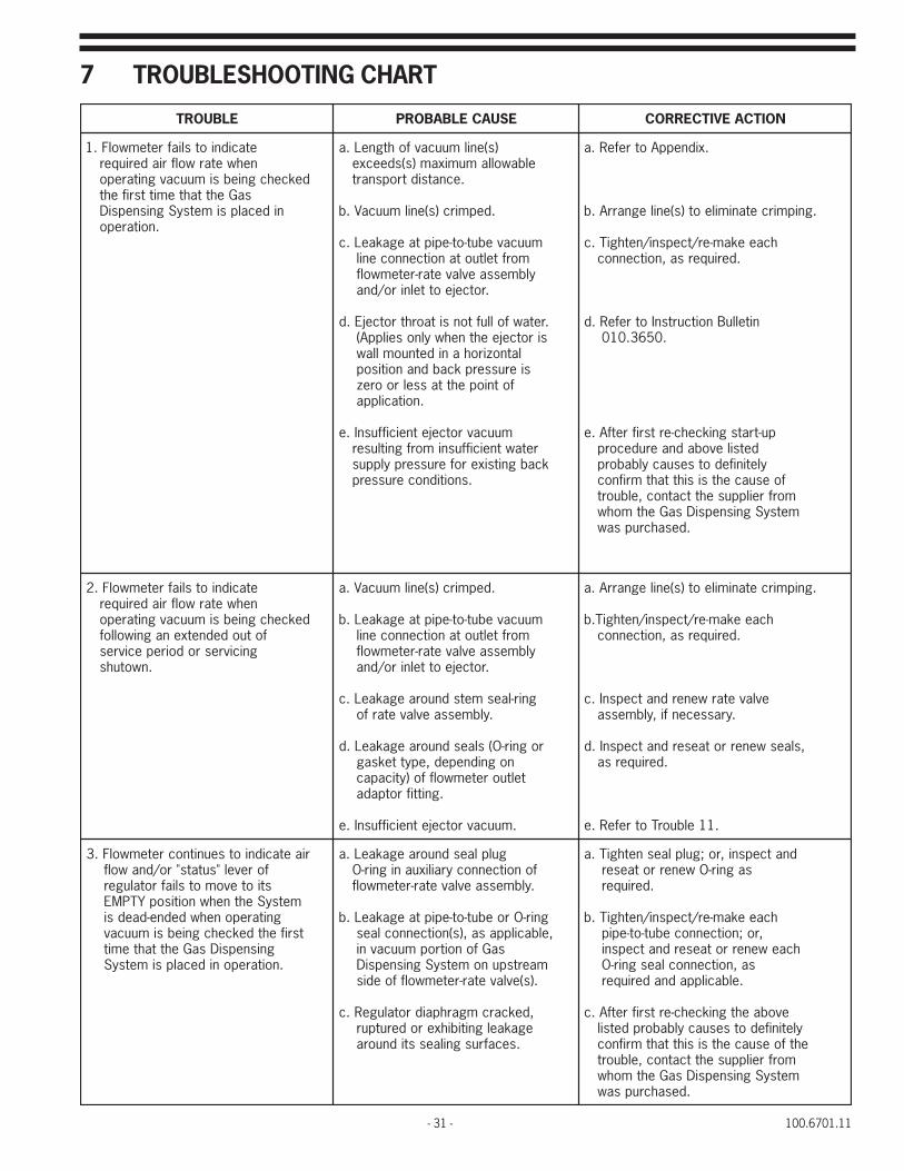
7 TROUBLESHOOTING CHART
ELBUORT ESUACELBABORP NOITCAEVITCERROC
etacidniotsliafretemwolF.1nehwetarwolfriaderiuqer
dekcehcgniebsimuucavgnitareposaGehttahtemittsrifeht
nidecalpsimetsySgnisnepsiD.noitarepo
)s(enilmuucavfohtgneL.aelbawollamumixam)s(sdeecxe
.ecnatsidtropsnart
.depmirc)s(enilmuucaV.b
muucavebut-ot-epiptaegakaeL.cmorfteltuotanoitcennocenil
ylbmessaevlavetar-retemwolf.rotcejeottelniro/dna
.retawfolluftonsitaorhtrotcejE.dsirotcejeehtnehwylnoseilppA(
latnozirohanidetnuomllawsierusserpkcabdnanoitisop
fotniopehttasselroorez.noitacilppa
muucavrotcejetneiciffusnI.eretawtneiciffusnimorfgnitluser
kcabgnitsixeroferusserpylppus.snoitidnocerusserp
.xidneppAotrefeR.a
.gnipmircetanimileot)s(enilegnarrA.b
hcaeekam-er/tcepsni/nethgiT.c.deriuqersa,noitcennoc
nitelluBnoitcurtsnIotrefeR.d.0563.010
pu-tratsgnikcehc-ertsrifretfA.edetsilevobadnaerudecorp
yletinifedotsesuacylbaborpfoesuacehtsisihttahtmrifnocmorfreilppusehttcatnoc,elbuortmetsySgnisnepsiDsaGehtmohw
.desahcrupsaw
etacidniotsliafretemwolF.2nehwetarwolfriaderiuqer
dekcehcgniebsimuucavgnitarepofotuodednetxenagniwollof
gnicivresrodoirepecivres.nwotuhs
.depmirc)s(enilmuucaV.a
muucavebut-ot-epiptaegakaeL.bmorfteltuotanoitcennocenil
ylbmessaevlavetar-retemwolf.rotcejeottelniro/dna
gnir-laesmetsdnuoraegakaeL.c.ylbmessaevlavetarfo
rognir-O(slaesdnuoraegakaeL.dnognidneped,epytteksag
teltuoretemwolffo)yticapac.gnittifrotpada
.muucavrotcejetneiciffusnI.e
.gnipmircetanimileot)s(enilegnarrA.a
hcaeekam-er/tcepsni/nethgiT.b.deriuqersa,noitcennoc
evlavetarwenerdnatcepsnI.c.yrassecenfi,ylbmessa
,slaeswenerrotaeserdnatcepsnI.d.deriuqersa
.11elbuorTotrefeR.e
riaetacidniotseunitnocretemwolF.3forevel"sutats"ro/dnawolfstiotevomotsliafrotaluger
metsySehtnehwnoitisopYTPMEgnitareponehwdedne-daedsi
tsrifehtdekcehcgniebsimuucavgnisnepsiDsaGehttahtemit
.noitareponidecalpsimetsyS
gulplaesdnuoraegakaeL.afonoitcennocyrailixuanignir-O.ylbmessaevlavetar-retemwolf
gnir-Oroebut-ot-epiptaegakaeL.b,elbacilppasa,)s(noitcennoclaes
saGfonoitropmuucavnimaertspunometsySgnisnepsiD.)s(evlavetar-retemwolffoedis
,dekcarcmgarhpaidrotalugeR.cegakaelgnitibihxeroderutpur
.secafrusgnilaesstidnuora
dnatcepsni,ro;gulplaesnethgiT.asagnir-Owenerrotaeser
.deriuqer
hcaeekam-er/tcepsni/nethgiT.b,ro;noitcennocebut-ot-epip
hcaewenerrotaeserdnatcepsnisa,noitcennoclaesgnir-O
.elbacilppadnaderiuqer
evobaehtgnikcehc-ertsrifretfA.cyletinifedotsesuacylbaborpdetsilehtfoesuacehtsisihttahtmrifnoc
morfreilppusehttcatnoc,elbuortmetsySgnisnepsiDsaGehtmohw
.desahcrupsaw

100.6701.11 - 32 -
ELBUORT ESUACELBABORP NOITCAEVITCERROC
riaetacidniotseunitnocretemwolF.4forevel"sutats"ro/dnawolfstiotevomotsliafrotaluger
metsysehtnehwnoitisopYTPMEgnitareponehwdedne-daedsi
gniwollofdekcehcgniebsimuucavdoirepecivres-fo-tuodednetxena
.nwodtuhsgnicivresro
gnir-OgulplaesdnuoraegakaeL.afonoitcennocyrailixuani
.ylbmessaevlavetar-retemwolf
gnir-Oroebut-ot-epiptaegakaeL.b,elbacilppasa,)s(noitcennoclaes
saGfonoitropmuucavnimaertspunometsySgnisnepsiD.)s(evlavetar-retemwolffoedis
rognir-O(slaesdnuoraegakaeL.cnognidneped,epytteksag
rotpadatelniretemwolffo)yticapac.gnittif
,dekcarcmgarhpaidrotalugeR.ddekaelgnitibihxeroderutpur.secafrusgnilaesstidnuora
dnatcepsniro;gulplaesnethgiT.asa,gnir-Owenerrotaeser
.deriuqer
-epiphcaeekam-er/tcepsni/nehgiT.bdnatcepsni,ro;noitcennocebut-otlaesgnir-Ohcaewenerrortaeser
dnaderiuqersanoitcennoc.elbacilppa
,slaeswenerrotaeserdnatcepsnI.c.deriuqersa
ekatdnarotalugerelbmessasiD.dsihttcerrocotspetsyrassecenlla
.noitidnoc
ebotdevresbotaolfretemwolF.5ro/dnanwoddnapugnicnuob
ebtonnacetarwolfsagmumixamfoesruocehtgniruddeveihca
.noitarepolamron
.ytridrotalugerfoevlavtelnisaG.a
.ytridevlavetaR.b
.ytridretemwolF.c
.ytridtelniretemwolfniretliF.dyticapacwolotylnoseilppA(
).sretemwolf
.ytridtelnirotalugerniretliF.e
.ytridtelnidlofinamniretliF.fnotrollawotylnoseilppA(
).srotalugerdetnuomreniatnoc
muucavnitniopemostaegakaeL.ggnisnepsiDsaGfonoitrop
.metsyS
.muucavrotcejetneiciffusnI.heveihcaotytilibaniotylnoseilppA(
).etarwolfsagmumixam
.evlavtelnisagnaelC.a
.evlavetarnaelC.b
.retemwolfnaelC.c
.retlifweneR.d
.retlifnaelC.e
.retlifweneR.f
dnasesuacylbaborpotrefeR.grednudetsilsnoitcaevitcerroc
.4dna2elbuorT
.11elbuorTotrefeR.h
edivorpotsliafwolfsagmumixaM.6laudiserlacimehcfolevelderised
.noitacilppafotniopta
muucavnitniopemostaegakaeL.ametsySgnisnepsiDsaGfonoitrop
.retemwolffoedismaertspuno
roretawfodnamedlacimehC.bdesaercnisahdiuqilssecorp
dengisedlanigiroevoba.yticapac
dnasesuacelbaborpotrefeR.arednudetsilsnoitcaevitcerroc
"4"elbuorT
mohwmorfreilppusehttcatnoC.bsawmetsySgnisnepsiDsaGeht
eziselbissoprofdesahcrup.yticapacregralaotesaercni
ootsedivorpwolfsagmuminiM.7laudiserlacimehcfolevelahgih
.noitacilppafotniopta
roretawfodnamedlacimehCwolebdesaercedsahdiuqilssecorp
.yticapacdengisedlanigiro
ehtmohwmorfreilppusehttcatnoCsawmetsySgnisnepsiDsaG
esaercedeziselbissoprofdesahcrup.yticapacrellamsaot
sagetacidniotsliafretemwolF.8foesruocehtgnirudwolf
""sutats""tubnoitarepolamronstinisniamerrotalugerforevel
.noitisopGNITAREPO
.depmirc)s(enilmuucaV.a
.desolcyltnetrevdanievlavetaR.b
.deggulpevlavetaR.c
.deggulpretemwolF.d
.deggulptelniretemwolfniretliF.eyticapacwolotylnoseilppA(
).sretemwolf
nonoitidnocmuucavfossoL.f.retemwolffoedismaertsnwod
etanimileot)s(enilegnarrA.a.gnipmirc
.evlavetarnepO.b
.evlavetarnaelC.c
.retemwolfnaelC.d
.retlifweneR.e
dnasesuacelbaborpotrefeR.frednudetsilsnoitcaevitcerroc
.2elbuorT

- 33 - 100.6701.11
ELBUORT ESUACYLBABORP NOITCAEVITCERROC
sevomrotalugerforevel""sutatS".9ehtgnirudnoitisopYTPMEstiot
noitarepolamronfoesruoc
ylnetrevdani)s(evlavylppussaG.a.desolc
.detsuahxeylppussaG.b
.deggulptelnirotalugerniretliF.c
rotalugerehtfoevlavtelnisaG.d.noitisopdesolcehtnikcuts
.deggulptelnidlofinamniretliF.enotrollawotylnoseilppA(
).srotalugerdetnuomreniatnoc
aot)s(evlavylppusllanepO.a.nrutllufenofolatot
.ylppushsinelpeR.b
.retlifweneR.c
.evlavtelnisagnaelC.d
.retlifweneR.e
roretemwolfnidetonretaW.01niardrotcejemorfgnigrahcsid
foemitta,elbacilppasa,teltuo.nwodtuhs
)s(evlavkcehcwolf-kcabrotcejE.a.ytluaf
riaperro/dnanaelc,tcepsnI.a.)s(evlavkcehcwolf-kcab
.muucavrotcejetneiciffusnI.11 sienilylppusretawnireniarts-Y.aelbaliavaehtgnicuderybereht,ytrid
.erusserpylppus
.gnilaestonevlavniardrotcejE.b)rotcejE71JE(
ehtnahtretaergsierusserpkcaB.cehtotdehcattagatehtnodetsileulav
gniwollofehtfoenorof,rotceje:snosaer
ton,tneserpfi,)s(evlavnoitulos.1.nepoylluf
yllaitrapsi,tneserpfi,enilnoitulos.2.dekcolb
fotnioptaerusserpkcab.3evobadesaercnisahnoitacilppa
.eulavlanigirosti
.ytridtaorhtro/dnaelzzonrotcejE.d
.retawfolluftonsitaorhtrotcejE.esirotcejeehtnehwylnoseilppA(
latnozirohanidetnuomllaworezsierusserpkcabdnanoitisop
.noitacilppafotnioptasselro
.nrowerataorhtdnaelzzonrotcejE.f
seodsihtfi,dna;reniarts-YnaelC.aotrefer,elbuortehttcerrocton
ehtni1erudecorPgnitoohselbuorTnoitcurtsnIfonoitceSgnitoohselbuorT
.0606.221nitelluB
erudecorPgnitoohselbuorTotrefeR.b.0606.221nitelluBnoitcurtsnIehtni2
noitulosnaelc;)s(evlavnoitulosnepO.cyllamronbafoesuacenimreted;enil
llaekatdnaerusserpkcabhgihsihttcerrocotspetsyrassecen
.noitidnoc
.taorhtro/dnaelzzonnaelC.d
.0563.010nitelluBnoitcutsnIotrefeR.e
.taorhtdnaelzzonwenahtiwecalpeR.f
.eniltnevmorfgnikaelsaG.21 tcerrocnitahtgnelmetsevlavtelnI.a.htgnel
noitalumuccatridsahtaesevlavtelnI.b.noitareporeporpgnitneverp
.taesevlavderocS.c
sa"891.2othtnelmetstsujdA.a.tsilstrapehtnidetacidni
.evlavtelnisagnaelC.b
.gulpdnataesevlavecalpeR.c
100.6701.11 - 34 -
APPENDIX

- 35 - 100.6701.11
VACUUM LINE(S) – LIMITS OF EXTENSIONThe vacuum line(s) connecting the regulator(s) to the ejector(s),either directly or indirectly, via one or more wall mountedmeter assembly, must not exceed the distance(s) presented inFigures 14 through 16 and the use of the factors provided inTable B, if applicable.
NOTE: The graphs in Figures 14 through 16 are for gasdispensing systems in which the interconnecting vacuum line(s)are the normally specified 5/8 inch (5/8² OD x ½² ID) flexibletubing. If the required gas flow rate(s) exceed the maximumallowable limits as determined by the graphs (and factors, ifapplicable), ¾ inch (or larger) schedule 80 PVC piping must beused in the construction of all (or portions of) the vacuum line(s).In such instances, it will be necessary to contact the supplierfrom whom the gas dispensing system was purchased fortechnical assistance.
The following examples demonstrate the use of the graphs (and factors) for determining the use of the graphs (and factors)for determining the maximum allowable transport distance(s) for chlorine gas dispensing systems. Determinationsestablishing the maximum allowable transport distance(s) for sulfur dioxide and ammonia gas dispensing systems are madein an identical manner by simply referencing Figures 15 and 16 respectively. The factors provided in Table B, whichconstitute interrelated split flow proportionality factors, are independent of the particular gas in question. Therefore, theyapply “across-the-board” for determining the “B” distances for either chlorine, sulfur dioxide, or ammonia split flow typegas dispensing systems.
Example ASystem: Single regulator type with integrally mounted meter-rate valve assembly having a maximum capacity of 100 lb/d(2 kg/h).
Determination: (Refer to Figures 13 and 14.) Since distance “A” is zero, the vacuum line between the meter-rate valveassembly and ejector (distance “B”) can be extended to any distance up to 720 feet.
Example BSystem: Single or dual regulator type with one wall mounted meter-rate valve assembly having a maximum capacity of300 lb/d (6 kg/h).
Determination: (Refer to Figures 13 and 14.) The vacuum lines between the single or furthest remote mounted regulator,as applicable, and the meter-rate valve assembly (distance “A”) and the meter-rate valve assembly and ejector (distance B)can be extended up to any combination of interrelated distances as ascertained from the graph, eg: 20 feet and 96 feet,80 feet and 58 feet, 120 feet and 34 feet, etc., respectively.
MUMIXAMYTICAPACMETSYS
)h/gk(d/bl
ETAR-RETEMWOLFLAUDIVIDNIFOYTICAPACSEILBMESSAEVLAV
)h/gk(d/bl
)1(05 )2(001 )4(002 )5(052 )6(003 )01(005
)1(05 00.1
)2(001 43.3 00.1
)4(002 80.11 13.3 00.1
)5(052 53.61 98.4 84.1 00.1
)6(003 62.22 66.6 10.2 63.1 00.1
)01(005 46.45 43.61 39.4 43.3 54.2 00.1
Figure 13 - Pictorial Representation of the ReferenceDistances Plotted in Figure 14 through 16.
NOTES:1. FOR SINGLE REGULATOR SYSTEMS, DISTANCE "A" IS ZERO
WHEN THE METER ASSEMBLY RATE VALVE IS MOUNTED ONTHE SIDE OF THE REGULATOR.
2. FOR DUAL REGULATOR SYSTEMS, DISTANCE "A" IS THELENGTH OF THE VACUUM LINE WHICH EXTENDS FROM THEFURTHEST REMOTE MOUNTED REGULATOR TO THE METERASSEMBLY (IES).
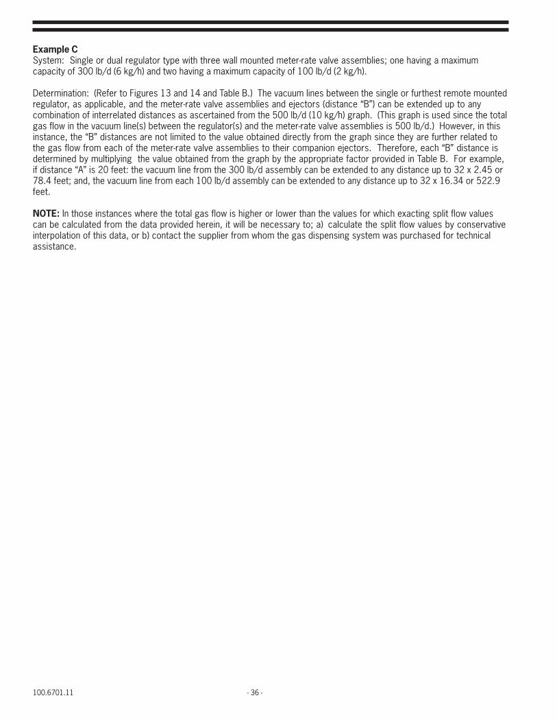
100.6701.11 - 36 -
Example CSystem: Single or dual regulator type with three wall mounted meter-rate valve assemblies; one having a maximumcapacity of 300 lb/d (6 kg/h) and two having a maximum capacity of 100 lb/d (2 kg/h).
Determination: (Refer to Figures 13 and 14 and Table B.) The vacuum lines between the single or furthest remote mountedregulator, as applicable, and the meter-rate valve assemblies and ejectors (distance “B”) can be extended up to anycombination of interrelated distances as ascertained from the 500 lb/d (10 kg/h) graph. (This graph is used since the totalgas flow in the vacuum line(s) between the regulator(s) and the meter-rate valve assemblies is 500 lb/d.) However, in thisinstance, the “B” distances are not limited to the value obtained directly from the graph since they are further related tothe gas flow from each of the meter-rate valve assemblies to their companion ejectors. Therefore, each “B” distance isdetermined by multiplying the value obtained from the graph by the appropriate factor provided in Table B. For example,if distance “A” is 20 feet: the vacuum line from the 300 lb/d assembly can be extended to any distance up to 32 x 2.45 or78.4 feet; and, the vacuum line from each 100 lb/d assembly can be extended to any distance up to 32 x 16.34 or 522.9feet.
NOTE: In those instances where the total gas flow is higher or lower than the values for which exacting split flow valuescan be calculated from the data provided herein, it will be necessary to; a) calculate the split flow values by conservativeinterpolation of this data, or b) contact the supplier from whom the gas dispensing system was purchased for technicalassistance.
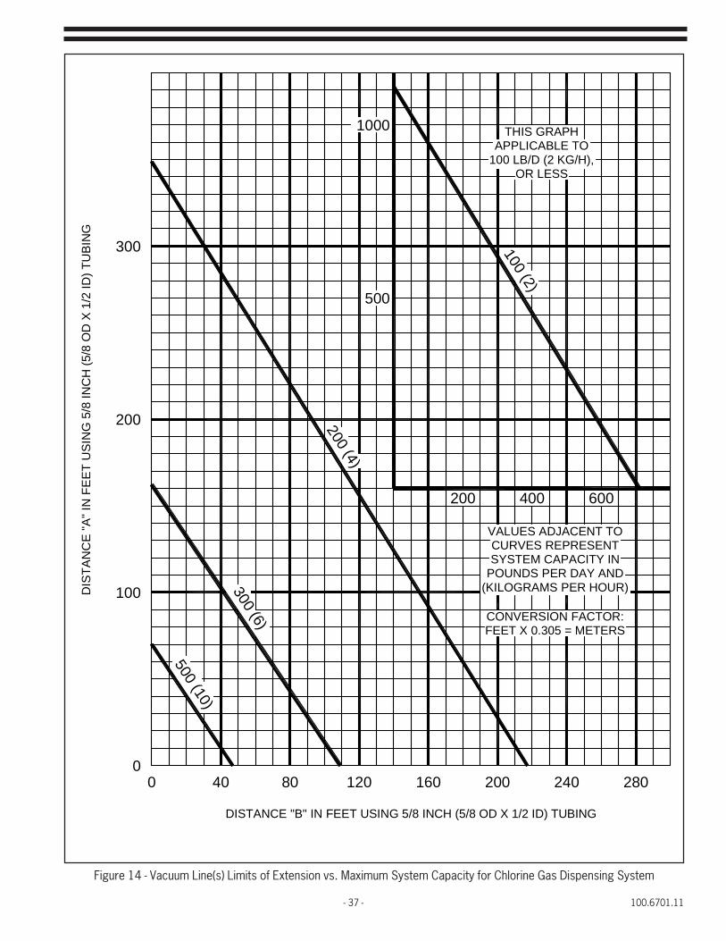
- 37 - 100.6701.11
Figure 14 - Vacuum Line(s) Limits of Extension vs. Maximum System Capacity for Chlorine Gas Dispensing System
300
DIS
TAN
CE
"A" I
N F
EET
US
ING
5/8
INC
H (5
/8 O
D X
1/2
ID) T
UBI
NG
120
DISTANCE "B" IN FEET USING 5/8 INCH (5/8 OD X 1/2 ID) TUBING
00 40 80
100
200
160 200 240 280
(KILOGRAMS PER HOUR)
CONVERSION FACTOR:FEET X 0.305 = METERS
CURVES REPRESENTVALUES ADJACENT TO
SYSTEM CAPACITY INPOUNDS PER DAY AND
400200
500
600
APPLICABLE TOTHIS GRAPH
OR LESS100 LB/D (2 KG/H),
1000
500 (10)
300 (6)
200 (4)
100 (2)

100.6701.11 - 38 -
Figure 15 - Vacuum Line(s) Limits of Extension vs. Maximum System Capacity forSulfur Dioxide Gas Dispensing System
200 (4)
DIS
TAN
CE
"A" I
N F
EE
T U
SIN
G 5
/8 IN
CH
(5/8
OD
X 1
/2 ID
) TU
BIN
G
DISTANCE "B" IN FEET USING 5/8 INCH (5/8 OD X 1/2 ID) TUBING
00
40 80
100
300 (6)
500 (10)
200120 160 240 280
POUNDS PER DAY ANDSYSTEM CAPACITY IN
VALUES ADJACENT TOCURVES REPRESENT
FEET X 0.305 = METERSCONVERSION FACTOR:
(KILOGRAMS PER HOUR)
200 400 600
200
300
1000
100 LB/D (2 KG/H),APPLICABLE TO
500
100 (2)
THIS GRAPH
OR LESS

- 39 - 100.6701.11
Figure 16 - Vacuum Line(s) Limits of Extension vs. Maximum System Capacity for Ammonia Gas Dispensing System
THIS GRAPHAPPLICABLE TO50 LB/D (1 KG/H),
(KILOGRAMS PER HOUR)
CONVERSION FACTOR:FEET X 0.305 = METERS
CURVES REPRESENTVALUES ADJACENT TO
SYSTEM CAPACITY INPOUNDS PER DAY AND
240
DISTANCE "B" IN FEET USING 5/8 INCH (5/8 OD X 1/2 ID) TUBING
100 (2)
DIS
TAN
CE
"A" I
N F
EE
T U
SIN
G 5
/8 IN
CH
(5/8
OD
X 1
/2 ID
) TU
BIN
G
00
40
100
250 (5)
80 120 200160
200 400
200
300
1000
500
50 (1)
OR LESS
280
600
100.6701.11 - 40 -
Represented by:Design improvements may be made without notice.
Severn Trent Services3000 Advance Lane Colmar, PA 18915Tel +1 215 997 4000 • Fax +1 215 997 4062Web: www.severntrentservices.comE-mail: [email protected]
Copyright 2011 Severn Trent ServicesAPR/11