institut max von laue - paul langevin fast real-time sans detectors charge division in individual,...
TRANSCRIPT
INSTITUT MAX VON LAUE - PAUL LANGEVIN
Fast Real-time SANS DetectorsFast Real-time SANS Detectors
Charge Division in Individual, 1-D Position-sensitive Gas Detectors
Patrick Van Esch.
INSTITUT MAX VON LAUE - PAUL LANGEVIN Patrick Van Esch S.D.N.TINX Septembre 2001
SANS-2MHz Millennium Project
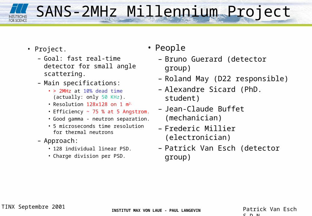
• Project.– Goal: fast real-time detector for
small angle scattering.– Main specifications:
• > 2MHz at 10% dead time (actually: only 50 KHz).
• Resolution 128x128 on 1 m2.
• Efficiency ~ 75 % at 5 Angstrom.• Good gamma - neutron separation.• 5 microseconds time resolution for
thermal neutrons
– Approach:• 128 individual linear PSD.• Charge division per PSD.
• People– Bruno Guerard (detector group)
– Roland May (D22 responsible)
– Alexandre Sicard (PhD. student)
– Jean-Claude Buffet (mechanician)
– Frederic Millier (electronician)
– Patrick Van Esch (detector group)

INSTITUT MAX VON LAUE - PAUL LANGEVIN Patrick Van Esch S.D.N.TINX Septembre 2001
Principle of Detector.
• Linear PSD detectors.
• 5 prototypes made by Reuter stokes.– 7.12 mm active diameter.
– 7.95 mm mechanical outer diameter.
– 1 meter long.
– About 10 bar He-3 gas.
Commercial 1 inch detector

INSTITUT MAX VON LAUE - PAUL LANGEVIN Patrick Van Esch S.D.N.TINX Septembre 2001
Resistive Charge Division
Event current0.5 pCUp to 500ns
Resistive anode wire 5.6 KOhm
Current noise i1
Current noise i2
Voltage noise v1 Voltage noise v2
Transimpedance preamplifier 1 Transimpedance preamplifier 2
Gaussian Shaper 1 Gaussian Shaper 2
Baseline correction 1 Baseline correction 2
Peak detection And ADC
Johnson current noise

INSTITUT MAX VON LAUE - PAUL LANGEVIN Patrick Van Esch S.D.N.TINX Septembre 2001
Principle of Resistive Charge Division
ZR
ZRLx
QA2
1
ZR
ZRLx
QB2
Charge Q collected at both ends divides in A and B when wire length is L, distance of impact from A is x, wire resistance is R and preamplifier impedance is Z.
ZR
R
L
xL
BA
BA
2
2
Extraction of position information: the fraction (A-B)/(A+B) codes the position in the interval (-1,1), reduced by the dynamic range.
Need for very low impedance (virtual ground).QBA

INSTITUT MAX VON LAUE - PAUL LANGEVIN Patrick Van Esch S.D.N.TINX Septembre 2001
Electronic Noise and Position Resolution
RTk
Rviii Bn
nSMR1682 2
22
...21
RTk
Rviii Bn
nSMRSMR42 2
22
...2...1
iii nSMR
2
...212White current spectral noise
densities seen by both amplifiers at the input are correlated.
dffHdfffHV ii nnSMR
222...
The output R.M.S. voltage noise can be calculated from the input current noise spectral density. In the case of white noise, this simplifies to a factor related to the transimpedance function.
222
1BABABA
BA
BABA
BA
These voltage noise values can be propagated in the position calculation, resulting in the position resolution due to electronic noise.

INSTITUT MAX VON LAUE - PAUL LANGEVIN Patrick Van Esch S.D.N.TINX Septembre 2001
Analogue Signal Processing
• Resistive charge division.– In contrast with capacitive
(single ended) detectors:• Faster shaping gives better S/N.
• Limited by overall conductance of wire (Johnson noise).
• Limited by integration time.
• Gaussian shaping.– Best compromise between:
• Time domain pulse width.
• Frequency domain noise bandwidth.
– Implementation as 4th order pure pole active filter, about 1MHz bandwidth.
• Unipolar pulse shaping:– Less dead time.
– But shift in baseline !
– Baseline correction:• Averages baseline over several
microseconds (eliminating noise).
• Corrects input signal with that amount.
• Reduction with a factor less than 1/10 of the initial baseline shift.
• No visible added noise.

INSTITUT MAX VON LAUE - PAUL LANGEVIN Patrick Van Esch S.D.N.TINX Septembre 2001
Impulse response.
5´10-7
1´10-6
1.5 ´10-6
2´10-6timeHsL
0.5
1
1.5
2
1 pC response HVL
pC
VH ampli
1.2
HzMH noise975

INSTITUT MAX VON LAUE - PAUL LANGEVIN Patrick Van Esch S.D.N.TINX Septembre 2001
Prototype Primary Charge
• HV bias: 100 V.
• Integration time: 10 microseconds.
• Using FET entry amplifier.
• Allows us to estimate absolute gain of detector.

INSTITUT MAX VON LAUE - PAUL LANGEVIN Patrick Van Esch S.D.N.TINX Septembre 2001
Spectra
1100 V 1300 V
1400 V 1500 V

INSTITUT MAX VON LAUE - PAUL LANGEVIN Patrick Van Esch S.D.N.TINX Septembre 2001
0 500 1000 1500 2000 2500BiasHVL1
5
10
50
100
500
1000
Absolute Charge Gain
Absolute Gain
8 mm Prototype 1 inch detector

INSTITUT MAX VON LAUE - PAUL LANGEVIN Patrick Van Esch S.D.N.TINX Septembre 2001
Spectrum
spectrum
0
200
400
600
800
1000
1200
1400
1600
1 190 379 568 757 946 1135 1324 1513 1702 1891
channel number (~2mV/channel)
cou
nts
pCC 65.0
pC
VH 1.2
pC
C
42.011

INSTITUT MAX VON LAUE - PAUL LANGEVIN Patrick Van Esch S.D.N.TINX Septembre 2001
Numerical application
HznVvn
0.1HzpA
in 6.1 KR 6.5
HzpA
SMRii 2.4...21
HzpA
SMRii 3.2...21
pCVH ampli
1.2
HzMH noise975
mVSMRVV 1.4...21 mV
SMRVV 2.2...21
pCQ 42.0
This results in a F.W.H.M. resolution of 5.5mm in the middle and 6.2mm on the borders.

INSTITUT MAX VON LAUE - PAUL LANGEVIN Patrick Van Esch S.D.N.TINX Septembre 2001
Linearity of Position CalibrationCalibration 10 bits y = -0,9922x + 1009,3010
R2 = 1,0000
0
200
400
600
800
1000
1200
0 100 200 300 400 500 600position (mm)
chan
nel n
umbe
r
Calibration 8 bits y = -0,248x + 251,898
R2 = 1,000
0
50
100
150
200
250
300
0 100 200 300 400 500 600position (mm)
chan
nel n
umbe
r
Residues
-1,5
-1
-0,5
0
0,5
1
1,5
2
0 100 200 300 400 500 600
position (mm)
re
sid
ue
(m
m)
8 bits10 bits

INSTITUT MAX VON LAUE - PAUL LANGEVIN Patrick Van Esch S.D.N.TINX Septembre 2001
Spatial Resolution
Spatial resolution
y = -0,0002x + 6,5674
y = -0,0004x + 5,7257
0
1
2
3
4
5
6
7
8
0 100 200 300 400 500 600
position (mm)
FW
HM
res
olut
ion
(mm
)
8 bits10 bits

INSTITUT MAX VON LAUE - PAUL LANGEVIN Patrick Van Esch S.D.N.TINX Septembre 2001
Count Rate Issues• Estimated dead time:
– 770 nanoseconds
• no extra dead time due to detector effects
• Implication for count rates (10% dead time correction):– 130 kHz per tube
– SANS - 16.6 MHz
20000 40000 60000 80000true rate
20000
40000
60000
80000
observed rate Observed rate versus true rate
20000 40000 60000 80000true countrate
80
81
82
83
84
decrease of relative efficiency as a function of countrate

INSTITUT MAX VON LAUE - PAUL LANGEVIN Patrick Van Esch S.D.N.TINX Septembre 2001
Spatial resolution at high count rates
• Large beam (35 mm FWHM) at about 100 KHz
• With and without a Cd sheet in beam length
• Spatial ‘resolution’ obtained ~9mm FWHM over entire length of detector.
• Reasonable upper estimate of true spatial resolution
200 mm : resolution
-5000
0
5000
10000
15000
20000
25000
30000
1 5 9
13 17 21 25 29 33 37
position (mm)
coun
ts
with Cd sheet
without Cd sheet
difference
gaussian fit
300 mm : resolution
-5000
0
5000
10000
15000
20000
25000
30000
35000
1 6 11 16 21 26 31
position (mm)
coun
ts
with Cd sheet
without Cd sheet
difference
gaussian fit

INSTITUT MAX VON LAUE - PAUL LANGEVIN Patrick Van Esch S.D.N.TINX Septembre 2001
Spectral behaviour at high count rate
• The upper part of the spectrum suffers a degradation at high counting rates. This does not impair significantly the detector performance.
logarithmic spectra as function of count rate
0
0,5
1
1,5
2
2,5
3
3,5
4
4,5
5
1 296 591 886 1181 1476 1771 2066 2361 2656
energy (channel number)
log
ari
thm
ic c
ou
nt r
ate 11KHz
24,9KHz
42,5KHz
64,4KHz
80,8KHz
117,7KHz
140KHz
INSTITUT MAX VON LAUE - PAUL LANGEVIN Patrick Van Esch S.D.N.TINX Septembre 2001
Efficiency Along Detector
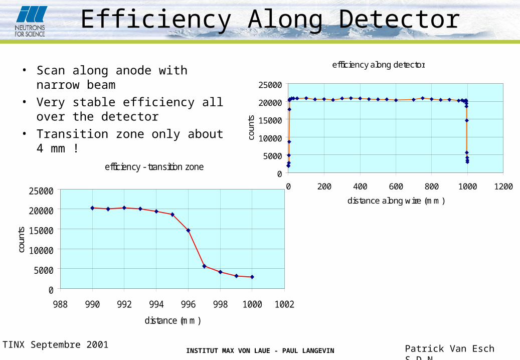
• Scan along anode with narrow beam
• Very stable efficiency all over the detector
• Transition zone only about 4 mm !
efficiency - transition zone
0
5000
10000
15000
20000
25000
988 990 992 994 996 998 1000 1002
distance (mm)
coun
ts
efficiency along detector
0
5000
10000
15000
20000
25000
0 200 400 600 800 1000 1200
distance along wire (mm)
coun
ts

INSTITUT MAX VON LAUE - PAUL LANGEVIN Patrick Van Esch S.D.N.TINX Septembre 2001
Conclusion
• Linear PSD based on the principle of resistive charge division offer great potential for building fast, large-scale neutron detectors.
• Resolution below 1cm at high count rates (>100kHz) can be obtained (6mm at low count rates).
• Very good linearity and uniformity.
• Electronics now exploits fully the potential of the detector.
• This opens up the possibility to have time resolution of the order of tens of microseconds.