instantaneous protection scheme for backup protection of...
TRANSCRIPT
Turk J Elec Eng & Comp Sci
(2017) 25: 3261 – 3272
c⃝ TUBITAK
doi:10.3906/elk-1511-9
Turkish Journal of Electrical Engineering & Computer Sciences
http :// journa l s . tub i tak .gov . t r/e lektr ik/
Research Article
Instantaneous protection scheme for backup protection of high-voltage
transmission lines
Syed Norazizul SYED NASIR∗, Abdullah Asuhaimi MOHD ZINFaculty of Electrical Engineering, Universiti Teknologi Malaysia, Johor, Malaysia
Received: 01.11.2015 • Accepted/Published Online: 30.12.2016 • Final Version: 30.07.2017
Abstract: The protection scheme focused on in this study is a typical protection system used in high-voltage systems
such as 132 kV, 275 kV, and 500 kV. The research will analyze the existing protection scheme for transmission lines that
the power utility has implemented and will propose a new protection scheme to improve the performance of the existing
scheme. The existing protection scheme currently implemented by the power utility for backup protection operation
has a longer fault-clearing time and no restoration time, and it does not utilize support relays. This study will focus
on a backup protection operation on high-voltage overhead transmission lines, which take up communication when the
main protection has failed to communicate, the relay has failed due to loss of DC supply, or the relay function itself
has been blocked. Moreover, all the support relays will be utilized in order to improve the protection system. The
improvement will consider three elements, which are the fault-clearing time, fast restoration time, and relay utilization.
Each improvement to the protection system will have its own philosophy and concrete rationale, which have advantages
or disadvantages for the transmission line. The effect of the improvement scheme will also consider the outcomes in
other schemes to ensure that time coordination does not overlap. Every possibility of a fault will be analyzed in order to
have a clear understanding of the effects of the three elements. CAPE software will be used as a tool for simulation and
to analyze its compatibility with real applications. CAPE software is able to model a real-life transmission line and is
also able to simulate faults in the tested area. The results of the simulation show that the backup protection operation
improved fault-clearing time and restoration time. It also increased the network’s system stability, particularly during
the occurrence of maximum fault currents.
Key words: Transmission line protection, backup protection, fault-clearing time, fast restoration, relay utilization
1. Introduction
A protection scheme is a vital provision that can have a massive impact on system operation. The effect
of a malfunction of the scheme may cause the wrong tripping sequence and can ruin the system, affecting
customers. Small setting discrepancies may even cause an increase in the fault-clearing time and cause system
feeding to the fault to be longer than the system design [1]. Unit protection is typically used as the main
protection, such as pilot wire and current differential relays, due to its capability to detect faults in a certain
area. Meanwhile, nonunit protection is used as backup protection, including distance and overcurrent relays,
which have the capability to detect faults in-zone and out-zone that are differentiated by time coordination. A
current differential relay at the transmission line relies on communication between substations to detect faults,
which will disable the protection for both substations during a loss of communication [2]. However, a distance
relay has its own benefits, unlike the existing differential relay; the failure of a distance relay on one side does
∗Correspondence: [email protected]
3261
SYED NASIR and MOHD ZIN/Turk J Elec Eng & Comp Sci
not result in failure of the protection on the other side [3]. The value of the distance relay is that it provides
engineers with the tools and flexibility to design more secure and dependable protection schemes [4].
Protection schemes for transmission lines are currently equipped with backup protection, although the
design scheme does not have a similar impact to that of the main protection. In this study, the standard scheme
implemented by the power utility in Malaysia will be used since it is a very practical scheme that has been
in use for a long time. The existing scheme will be based on the TNB Transmission System Protection and
Control Code of Practice booklet [5].
1.1. Project background
Transmission lines are the typical medium used to transmit power from generation to distribution. In Malaysia,
transmission lines are designed for high-voltage levels such as 132 kV, 275 kV, and 500 kV, depending on the
estimation of the system’s needs. The main reason behind this principle is to reduce losses during transmission
of bulk power [5].
A study regarding the power utility in Malaysia was conducted to define the capability of the system to
feed faults in order to protect the high-voltage apparatus and the system as a whole. The protection scheme
design must be in line with the competency of the apparatus and the system. Competency consists of the
minimum requirements needed in the design of the protection schemes. For example, the fault-clearing time
for a 132-kV system must be below or equal to 150 ms [5], while the fault-clearing time for 275-kV and 500-kV
lines must be below or equal to 100 ms [5]. These levels are used as a limit for the main protection.
Using the fault-clearing time as a reference will help the designer to coordinate a time for the breaker to
be opened during a fault as required. Rather than only affecting the coordination time, it will also cause an
increase in the specification for breaker time opening, relay detection, and much more in order to satisfy the
fault-clearing time requirement. The voltage level on the transmission line, its length, its distance to sources,
load flows, and also the stability parameters are examples of the effects of the protection scheme for typical
transmission lines [6].
In addition, transmission lines are normally equipped with an autoreclose function that is designed to
minimize the restoration time during a transient fault, such as one caused by lightning. Normally, in high-
voltage applications, the utility will only tolerate a single reclose because the outcome of the fault current can
cause a major voltage dip, and this will reduce the lifecycle of a sensitive high-voltage apparatus such as a
circuit breaker [7]. However, the autoreclose scheme is only available during the main protection operation and
remains idle during backup protection operations [5]. This causes a long restoration time for transmission lines,
even when faced with a transient fault that can supposedly be reduced if an autoreclose function is embedded
in the backup protection operation.
2. Literature review
The protection scheme is designed based on the overall system, which considers many parameters such as the
fault current level, equipment rating, and power system stability. Each power system is designed to withstand
some fault level depending on preliminary studies. Hence, each primary apparatus is equipped with protection
schemes that protect the apparatus from failing. Certain protection schemes have been designed to maintain
stability, and users are trained to make a proper decision in restoring the system to normal conditions after
a fault [8]. The protection schemes that are generally implemented in transmission lines are equipped with
appropriate autoreclose facilities that enable fast restoration and power system stability. The fault-clearing
3262
SYED NASIR and MOHD ZIN/Turk J Elec Eng & Comp Sci
system is a system that detects faults and isolates them. The system design needs to take into consideration
that the failure of any component in a fault clearance system should not result in a complete failure to clear the
power system fault or abnormalities. This can be achieved when considering the backup protection, which can
be a local backup or a remote backup for every possible component failure. The new proposed protection scheme
will focus on the fault-clearing time, fast restoration, and relay utilization. The best backup protection for all
three criteria will be designed. In addition, time coordination will also be taken into account when dealing with
these three parameters. The protection scheme that is implemented by the power utility in Malaysia consists
of current differential protection (87CD), distance protection (21Z), autoreclose relay (79AR), and synchronous
relay (25SYN).
2.1. Current differential protection
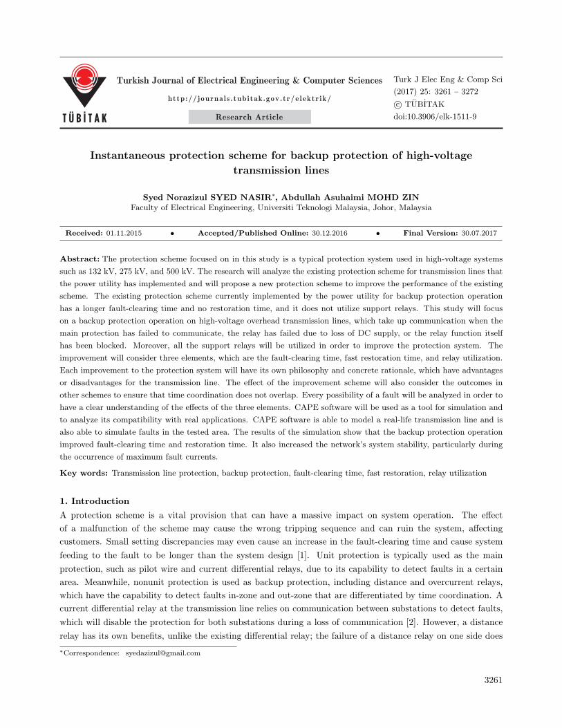
Current differential protection is a unit protection. The philosophy of unit protection is related to Kirchhoff’s
current law, which states that the value of current leaving a circuit must be equal to the value of that entering
the circuit. Current differential protection is also immune to the power swing phenomenon, which causes the
protection to be more stable and reliable during mass changing of the load flow in the system [9]. For a fault
within its zone of protection, a relay will instantaneously operate the scheme in order to isolate the fault through
the dedicated circuit breaker. Nevertheless, this scheme should remain stable or inoperative for faults outside
of its zone. This type of zone of protection is demonstrated in Figure 1. As previously mentioned, both vector
currents are meant to cancel each other out in order to have zero differential, but this summation will create a
larger current if a fault occurs.
Figure 1. Protection zone for unit protection.
2.2. Distance protection
Distance protection is currently a nonunit protection, one that protects transmission lines by separating them
into zones. All inputs are therefore stand-alone only on one side. Distance protection relay is used as backup
protection due to the measurement inaccuracy of the impedance during faults, especially when dealing with
high-resistance faults that may cause an increase in impedance and lead to an incorrect zone of operation. The
distance relay for zone 1 requires permission input from the main protection relay to be activated. The input
from the main protection relay only functions with the availability of DC supply to the main relay, during relay
function failure, or when a communication failure occurs between both ends [5].
The distance relays algorithm is capable of measuring the impedance between the relay and the fault
location. However, it depends on the resistance occurring at the fault. If there is a low resistance fault,
the impedance is approximately similar to the distance from the relay to the fault location, but for a higher
3263
SYED NASIR and MOHD ZIN/Turk J Elec Eng & Comp Sci
resistance fault, it may cause an inaccurate assessment of the distance. Current and voltage inputs from the
dedicated transmission lines are required for the distance relay to quantify the impedance. A distance relay
is designed to be segregated into several zones, which are differentiated by the impedance value range. Every
zone has its own timer that is coordinated based on the application for the transmission lines. The relay will
be operated according to the respective zones and a dedicated timer, which can indirectly separate the fault
locations, making it easy for faultfinders to find the fault locations [1].
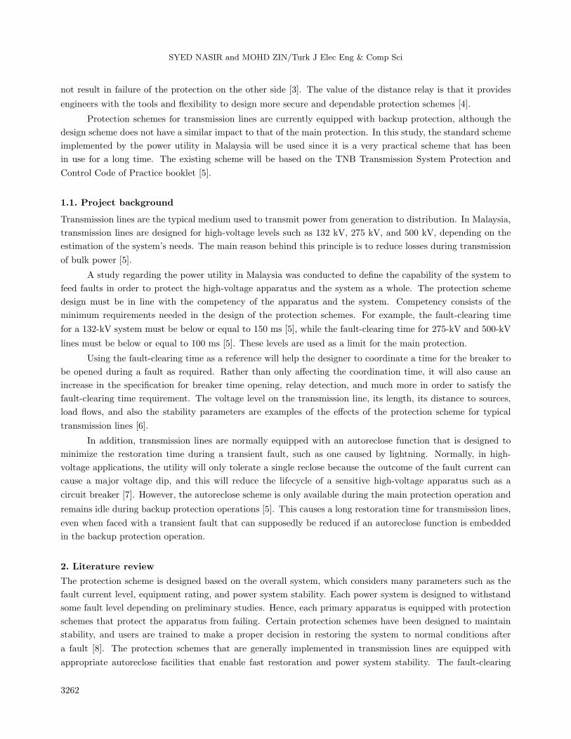
Distance zones are practically divided into four parts; three zones are dedicated for forward zone protec-
tion while the other one is for reverse zone protection [5]. The zones’ protection is illustrated in Figure 2. The
protection for dedicated transmission lines consists of the whole of zone 1 and a part of zone 2, which are differ-
entiated by a timer. Normally, 70% to 85% of line length is covered by the protection from zone 1 [5] due to the
inaccuracy of the apparent impedance and protection relay measurements to operate the remote transmission
line fault. The remaining length will be concealed by another zone, which will also cover a part of the remote
transmission line. This is known as zone 2, which has a timer delay that is designed to be inactive during faults
that must be cleared by the distance protection of zone 1 at local and remote sides. This coordination delay
depends on system stability, where current practice for the power utility in Malaysia is 0.45 s [8].
Figure 2. Coordination distance relay zones for the transmission line.
2.3. Autoreclose scheme
High-voltage transmission lines will deliver a bulk supply from the generation to the customer. Disturbance on
the transmission lines may contribute stress to the overall system even if it only involves one transmission line.
When the transmission line experiences a fault, the circuit breaker will open and isolate the fault. Normalizing
of the transmission line needs to be done manually, which will take longer. Generally, autoreclose schemes help
to maintain system stability and synchronism. In fact, most faults on overhead transmission lines are transient
faults. Malaysia, which has a high keraunic level of about 180 thunder days per year, suffers a high-transient
fault rate, and 70% of the faults are transient in nature, indirectly affecting the reliability and quality of supply
to customers [7]. Faults can be divided into two types: transient and permanent. An example of a transient
fault is lightning, which, as mentioned earlier, is a major contributor to fault statistics. From the analysis, a
transient fault occurs for a short duration. Transient faults can therefore be cleared by temporarily isolating
the transmission line to tolerate the clearance of the fault [10]. The autoreclose relay generally functions to
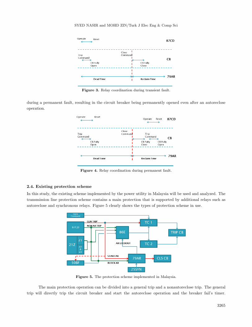
reclose the circuit breaker after considering some parameters engaged by the synchronous relay. Figure 3 shows
the relay coordination when dealing with a transient fault. As a result, autoreclosing can reduce the outage
time arising from faults with fast restoration of the transient fault, resulting in only short power interruptions
for customers [10].
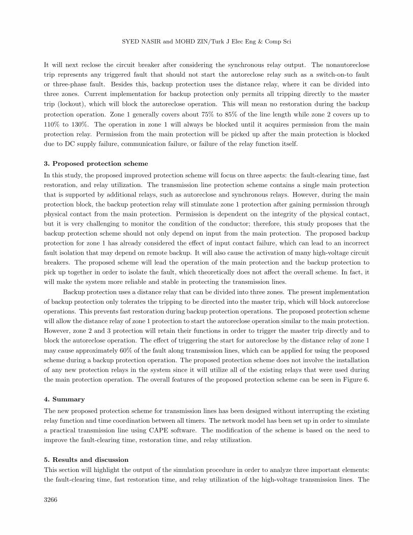
Permanent faults are those that are not yet cleared, even after the reclosing process. Permanent faults
will not be discussed in this study since they take a longer time to remove. Figure 4 shows the relay coordination
3264
SYED NASIR and MOHD ZIN/Turk J Elec Eng & Comp Sci
Figure 3. Relay coordination during transient fault.
during a permanent fault, resulting in the circuit breaker being permanently opened even after an autoreclose
operation.
Figure 4. Relay coordination during permanent fault.
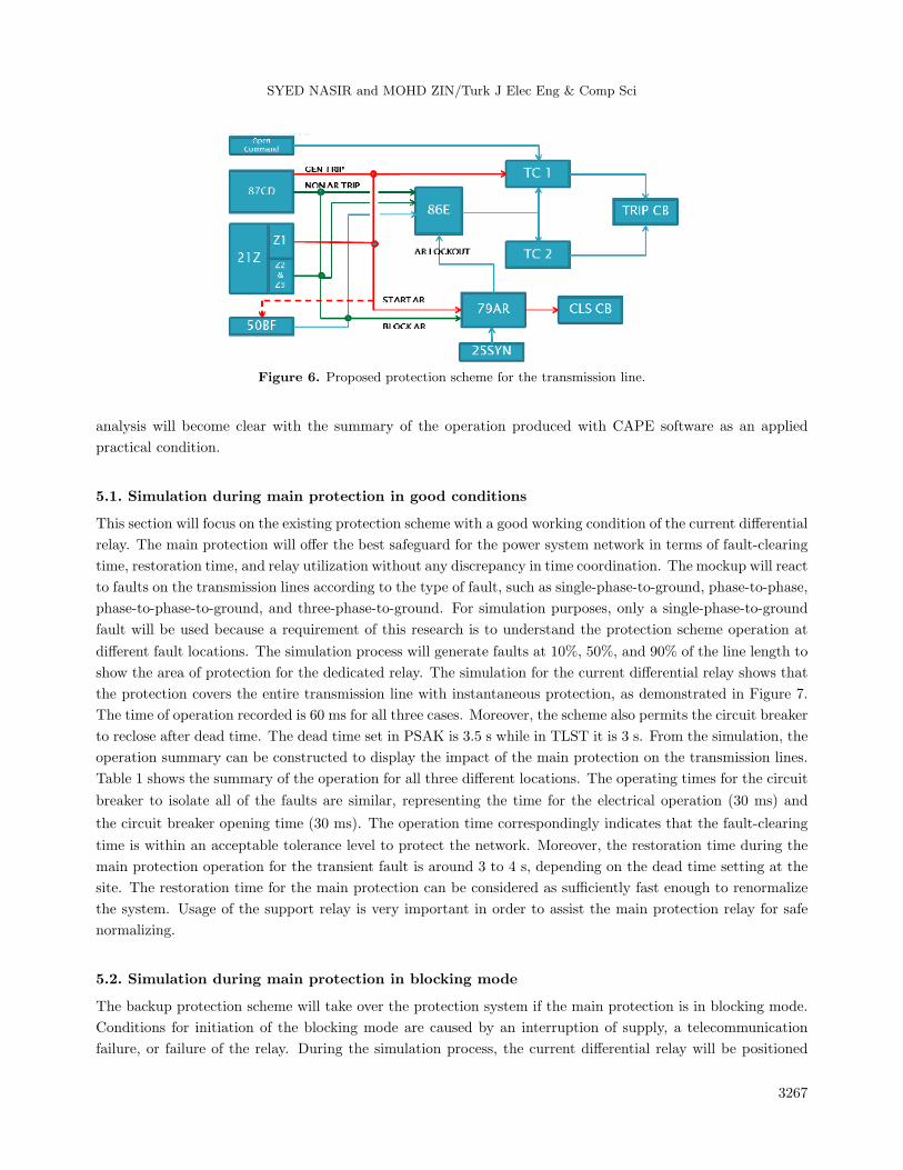
2.4. Existing protection scheme
In this study, the existing scheme implemented by the power utility in Malaysia will be used and analyzed. The
transmission line protection scheme contains a main protection that is supported by additional relays such as
autoreclose and synchronous relays. Figure 5 clearly shows the types of protection scheme in use.
Figure 5. The protection scheme implemented in Malaysia.
The main protection operation can be divided into a general trip and a nonautoreclose trip. The general
trip will directly trip the circuit breaker and start the autoreclose operation and the breaker fail’s timer.
3265
SYED NASIR and MOHD ZIN/Turk J Elec Eng & Comp Sci
It will next reclose the circuit breaker after considering the synchronous relay output. The nonautoreclose
trip represents any triggered fault that should not start the autoreclose relay such as a switch-on-to fault
or three-phase fault. Besides this, backup protection uses the distance relay, where it can be divided into
three zones. Current implementation for backup protection only permits all tripping directly to the master
trip (lockout), which will block the autoreclose operation. This will mean no restoration during the backup
protection operation. Zone 1 generally covers about 75% to 85% of the line length while zone 2 covers up to
110% to 130%. The operation in zone 1 will always be blocked until it acquires permission from the main
protection relay. Permission from the main protection will be picked up after the main protection is blocked
due to DC supply failure, communication failure, or failure of the relay function itself.
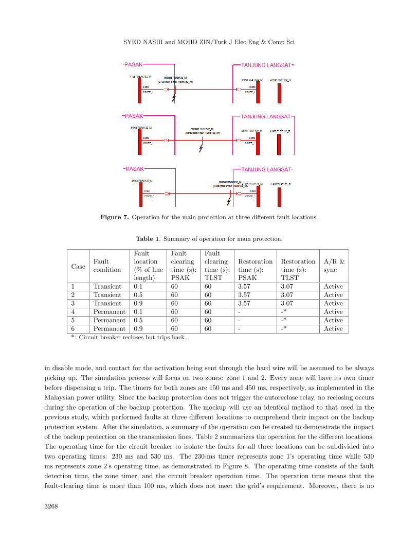
3. Proposed protection scheme
In this study, the proposed improved protection scheme will focus on three aspects: the fault-clearing time, fast
restoration, and relay utilization. The transmission line protection scheme contains a single main protection
that is supported by additional relays, such as autoreclose and synchronous relays. However, during the main
protection block, the backup protection relay will stimulate zone 1 protection after gaining permission through
physical contact from the main protection. Permission is dependent on the integrity of the physical contact,
but it is very challenging to monitor the condition of the conductor; therefore, this study proposes that the
backup protection scheme should not only depend on input from the main protection. The proposed backup
protection for zone 1 has already considered the effect of input contact failure, which can lead to an incorrect
fault isolation that may depend on remote backup. It will also cause the activation of many high-voltage circuit
breakers. The proposed scheme will lead the operation of the main protection and the backup protection to
pick up together in order to isolate the fault, which theoretically does not affect the overall scheme. In fact, it
will make the system more reliable and stable in protecting the transmission lines.
Backup protection uses a distance relay that can be divided into three zones. The present implementation
of backup protection only tolerates the tripping to be directed into the master trip, which will block autoreclose
operations. This prevents fast restoration during backup protection operations. The proposed protection scheme
will allow the distance relay of zone 1 protection to start the autoreclose operation similar to the main protection.
However, zone 2 and 3 protection will retain their functions in order to trigger the master trip directly and to
block the autoreclose operation. The effect of triggering the start for autoreclose by the distance relay of zone 1
may cause approximately 60% of the fault along transmission lines, which can be applied for using the proposed
scheme during a backup protection operation. The proposed protection scheme does not involve the installation
of any new protection relays in the system since it will utilize all of the existing relays that were used during
the main protection operation. The overall features of the proposed protection scheme can be seen in Figure 6.
4. Summary
The new proposed protection scheme for transmission lines has been designed without interrupting the existing
relay function and time coordination between all timers. The network model has been set up in order to simulate
a practical transmission line using CAPE software. The modification of the scheme is based on the need to
improve the fault-clearing time, restoration time, and relay utilization.
5. Results and discussion
This section will highlight the output of the simulation procedure in order to analyze three important elements:
the fault-clearing time, fast restoration time, and relay utilization of the high-voltage transmission lines. The
3266
SYED NASIR and MOHD ZIN/Turk J Elec Eng & Comp Sci
Figure 6. Proposed protection scheme for the transmission line.
analysis will become clear with the summary of the operation produced with CAPE software as an applied
practical condition.
5.1. Simulation during main protection in good conditions
This section will focus on the existing protection scheme with a good working condition of the current differential
relay. The main protection will offer the best safeguard for the power system network in terms of fault-clearing
time, restoration time, and relay utilization without any discrepancy in time coordination. The mockup will react
to faults on the transmission lines according to the type of fault, such as single-phase-to-ground, phase-to-phase,
phase-to-phase-to-ground, and three-phase-to-ground. For simulation purposes, only a single-phase-to-ground
fault will be used because a requirement of this research is to understand the protection scheme operation at
different fault locations. The simulation process will generate faults at 10%, 50%, and 90% of the line length to
show the area of protection for the dedicated relay. The simulation for the current differential relay shows that
the protection covers the entire transmission line with instantaneous protection, as demonstrated in Figure 7.
The time of operation recorded is 60 ms for all three cases. Moreover, the scheme also permits the circuit breaker
to reclose after dead time. The dead time set in PSAK is 3.5 s while in TLST it is 3 s. From the simulation, the
operation summary can be constructed to display the impact of the main protection on the transmission lines.
Table 1 shows the summary of the operation for all three different locations. The operating times for the circuit
breaker to isolate all of the faults are similar, representing the time for the electrical operation (30 ms) and
the circuit breaker opening time (30 ms). The operation time correspondingly indicates that the fault-clearing
time is within an acceptable tolerance level to protect the network. Moreover, the restoration time during the
main protection operation for the transient fault is around 3 to 4 s, depending on the dead time setting at the
site. The restoration time for the main protection can be considered as sufficiently fast enough to renormalize
the system. Usage of the support relay is very important in order to assist the main protection relay for safe
normalizing.
5.2. Simulation during main protection in blocking mode
The backup protection scheme will take over the protection system if the main protection is in blocking mode.
Conditions for initiation of the blocking mode are caused by an interruption of supply, a telecommunication
failure, or failure of the relay. During the simulation process, the current differential relay will be positioned
3267
SYED NASIR and MOHD ZIN/Turk J Elec Eng & Comp Sci
Figure 7. Operation for the main protection at three different fault locations.
Table 1. Summary of operation for main protection.
Case
Fault Fault FaultFault location clearing clearing Restoration Restoration A/R &condition (% of line time (s): time (s): time (s): time (s): sync
length) PSAK TLST PSAK TLST1 Transient 0.1 60 60 3.57 3.07 Active2 Transient 0.5 60 60 3.57 3.07 Active3 Transient 0.9 60 60 3.57 3.07 Active4 Permanent 0.1 60 60 - -* Active5 Permanent 0.5 60 60 - -* Active6 Permanent 0.9 60 60 - -* Active*: Circuit breaker recloses but trips back.
in disable mode, and contact for the activation being sent through the hard wire will be assumed to be always
picking up. The simulation process will focus on two zones: zone 1 and 2. Every zone will have its own timer
before dispensing a trip. The timers for both zones are 150 ms and 450 ms, respectively, as implemented in the
Malaysian power utility. Since the backup protection does not trigger the autoreclose relay, no reclosing occurs
during the operation of the backup protection. The mockup will use an identical method to that used in the
previous study, which performed faults at three different locations to comprehend their impact on the backup
protection system. After the simulation, a summary of the operation can be created to demonstrate the impact
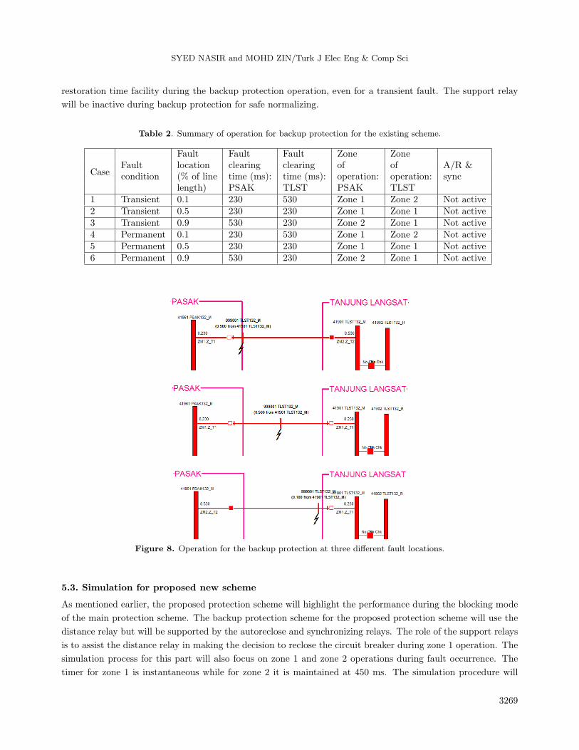
of the backup protection on the transmission lines. Table 2 summarizes the operation for the different locations.
The operating time for the circuit breaker to isolate the faults for all three locations can be subdivided into
two operating times: 230 ms and 530 ms. The 230-ms timer represents zone 1’s operating time while 530
ms represents zone 2’s operating time, as demonstrated in Figure 8. The operating time consists of the fault
detection time, the zone timer, and the circuit breaker operation time. The operation time means that the
fault-clearing time is more than 100 ms, which does not meet the grid’s requirement. Moreover, there is no
3268
SYED NASIR and MOHD ZIN/Turk J Elec Eng & Comp Sci
restoration time facility during the backup protection operation, even for a transient fault. The support relay
will be inactive during backup protection for safe normalizing.
Table 2. Summary of operation for backup protection for the existing scheme.
Case
Fault Fault Fault Zone ZoneFault location clearing clearing of of A/R &condition (% of line time (ms): time (ms): operation: operation: sync
length) PSAK TLST PSAK TLST1 Transient 0.1 230 530 Zone 1 Zone 2 Not active2 Transient 0.5 230 230 Zone 1 Zone 1 Not active3 Transient 0.9 530 230 Zone 2 Zone 1 Not active4 Permanent 0.1 230 530 Zone 1 Zone 2 Not active5 Permanent 0.5 230 230 Zone 1 Zone 1 Not active6 Permanent 0.9 530 230 Zone 2 Zone 1 Not active
Figure 8. Operation for the backup protection at three different fault locations.
5.3. Simulation for proposed new scheme
As mentioned earlier, the proposed protection scheme will highlight the performance during the blocking mode
of the main protection scheme. The backup protection scheme for the proposed protection scheme will use the
distance relay but will be supported by the autoreclose and synchronizing relays. The role of the support relays
is to assist the distance relay in making the decision to reclose the circuit breaker during zone 1 operation. The
simulation process for this part will also focus on zone 1 and zone 2 operations during fault occurrence. The
timer for zone 1 is instantaneous while for zone 2 it is maintained at 450 ms. The simulation procedure will
3269
SYED NASIR and MOHD ZIN/Turk J Elec Eng & Comp Sci
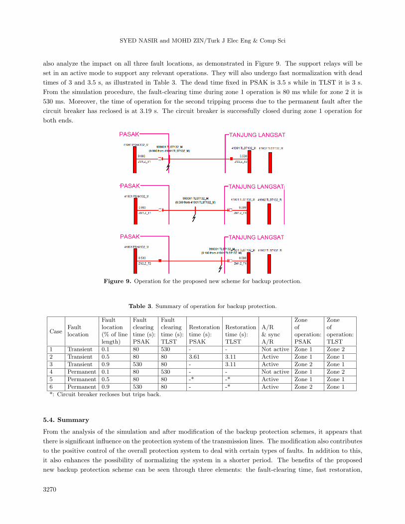
also analyze the impact on all three fault locations, as demonstrated in Figure 9. The support relays will be
set in an active mode to support any relevant operations. They will also undergo fast normalization with dead
times of 3 and 3.5 s, as illustrated in Table 3. The dead time fixed in PSAK is 3.5 s while in TLST it is 3 s.
From the simulation procedure, the fault-clearing time during zone 1 operation is 80 ms while for zone 2 it is
530 ms. Moreover, the time of operation for the second tripping process due to the permanent fault after the
circuit breaker has reclosed is at 3.19 s. The circuit breaker is successfully closed during zone 1 operation for
both ends.
Figure 9. Operation for the proposed new scheme for backup protection.
Table 3. Summary of operation for backup protection.
Case
Fault Fault Fault Zone ZoneFault location clearing clearing Restoration Restoration A/R of oflocation (% of line time (s): time (s): time (s): time (s): & sync operation: operation:
length) PSAK TLST PSAK TLST A/R PSAK TLST
1 Transient 0.1 80 530 - - Not active Zone 1 Zone 2
2 Transient 0.5 80 80 3.61 3.11 Active Zone 1 Zone 1
3 Transient 0.9 530 80 - 3.11 Active Zone 2 Zone 1
4 Permanent 0.1 80 530 - - Not active Zone 1 Zone 2
5 Permanent 0.5 80 80 -* -* Active Zone 1 Zone 1
6 Permanent 0.9 530 80 - -* Active Zone 2 Zone 1
*: Circuit breaker recloses but trips back.
5.4. Summary
From the analysis of the simulation and after modification of the backup protection schemes, it appears that
there is significant influence on the protection system of the transmission lines. The modification also contributes
to the positive control of the overall protection system to deal with certain types of faults. In addition to this,
it also enhances the possibility of normalizing the system in a shorter period. The benefits of the proposed
new backup protection scheme can be seen through three elements: the fault-clearing time, fast restoration,
3270
SYED NASIR and MOHD ZIN/Turk J Elec Eng & Comp Sci
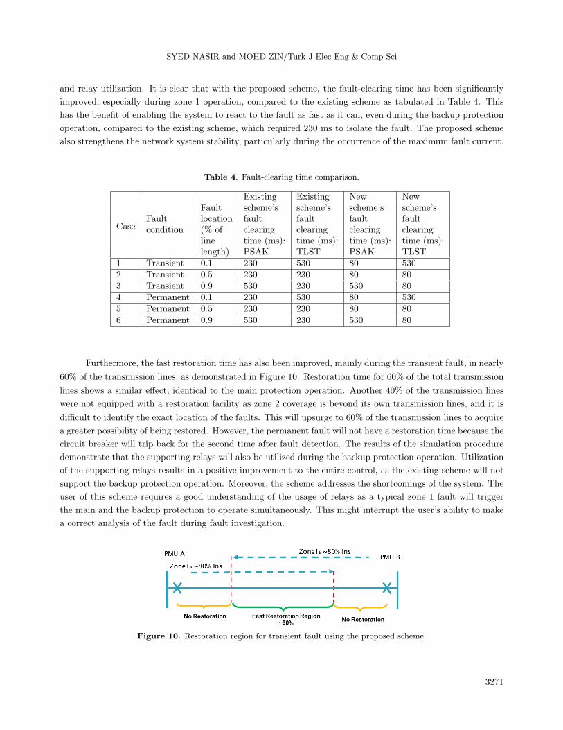
and relay utilization. It is clear that with the proposed scheme, the fault-clearing time has been significantly
improved, especially during zone 1 operation, compared to the existing scheme as tabulated in Table 4. This
has the benefit of enabling the system to react to the fault as fast as it can, even during the backup protection
operation, compared to the existing scheme, which required 230 ms to isolate the fault. The proposed scheme
also strengthens the network system stability, particularly during the occurrence of the maximum fault current.
Table 4. Fault-clearing time comparison.
Case
Existing Existing New NewFault scheme’s scheme’s scheme’s scheme’s
Fault location fault fault fault faultcondition (% of clearing clearing clearing clearing
line time (ms): time (ms): time (ms): time (ms):length) PSAK TLST PSAK TLST
1 Transient 0.1 230 530 80 5302 Transient 0.5 230 230 80 803 Transient 0.9 530 230 530 804 Permanent 0.1 230 530 80 5305 Permanent 0.5 230 230 80 806 Permanent 0.9 530 230 530 80
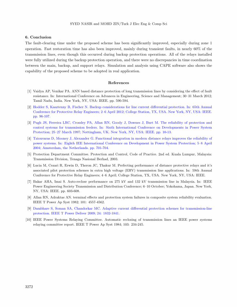
Furthermore, the fast restoration time has also been improved, mainly during the transient fault, in nearly
60% of the transmission lines, as demonstrated in Figure 10. Restoration time for 60% of the total transmission
lines shows a similar effect, identical to the main protection operation. Another 40% of the transmission lines
were not equipped with a restoration facility as zone 2 coverage is beyond its own transmission lines, and it is
difficult to identify the exact location of the faults. This will upsurge to 60% of the transmission lines to acquire
a greater possibility of being restored. However, the permanent fault will not have a restoration time because the
circuit breaker will trip back for the second time after fault detection. The results of the simulation procedure
demonstrate that the supporting relays will also be utilized during the backup protection operation. Utilization
of the supporting relays results in a positive improvement to the entire control, as the existing scheme will not
support the backup protection operation. Moreover, the scheme addresses the shortcomings of the system. The
user of this scheme requires a good understanding of the usage of relays as a typical zone 1 fault will trigger
the main and the backup protection to operate simultaneously. This might interrupt the user’s ability to make
a correct analysis of the fault during fault investigation.
Figure 10. Restoration region for transient fault using the proposed scheme.
3271
SYED NASIR and MOHD ZIN/Turk J Elec Eng & Comp Sci
6. Conclusion
The fault-clearing time under the proposed scheme has been significantly improved, especially during zone 1
operation. Fast restoration time has also been improved, mainly during transient faults, in nearly 60% of the
transmission lines, even though this occurred during backup protection operations. All of the relays installed
were fully utilized during the backup protection operation, and there were no discrepancies in time coordination
between the main, backup, and support relays. Simulation and analysis using CAPE software also shows the
capability of the proposed scheme to be adopted in real application.
References
[1] Vaidya AP, Venikar PA. ANN based distance protection of long transmission lines by considering the effect of fault
resistance. In: International Conference on Advances in Engineering, Science and Management; 30–31 March 2012;
Tamil Nadu, India. New York, NY, USA: IEEE. pp. 590-594.
[2] Hodder S, Kasztenny B, Fischer N. Backup considerations for line current differential protection. In: 65th Annual
Conference for Protective Relay Engineers; 2–6 April 2012; College Station, TX, USA. New York, NY, USA: IEEE.
pp. 96-107.
[3] Pugh JS, Ferreira LRC, Crossley PA, Allan RN, Goody J, Downes J, Burt M. The reliability of protection and
control systems for transmission feeders. In: Sixth International Conference on Developments in Power System
Protection; 25–27 March 1997; Nottingham, UK. New York, NY, USA: IEEE. pp. 10-13.
[4] Tziouvaras D, Mooney J, Alexander G. Functional integration in modern distance relays improves the reliability of
power systems. In: Eighth IEE International Conference on Development in Power System Protection; 5–8 April
2004; Amsterdam, the Netherlands. pp. 701-704.
[5] Protection Department Committee. Protection and Control, Code of Practice. 2nd ed. Kuala Lumpur, Malaysia:
Transmission Division, Tenaga Nasional Berhad, 2003.
[6] Lucia M, Cezari R, Erwin D, Theron JC, Thakur M. Perfecting performance of distance protective relays and it’s
associated pilot protection schemes in extra high voltage (EHV) transmission line applications. In: 59th Annual
Conference for Protective Relay Engineers; 4–6 April; College Station, TX, USA. New York, NY, USA: IEEE.
[7] Bakar AHA, Imai S. Auto-reclose performance on 275 kV and 132 kV transmission line in Malaysia. In: IEEE
Power Engineering Society Transmission and Distribution Conference; 6–10 October; Yokohama, Japan. New York,
NY, USA: IEEE. pp. 603-608.
[8] Allan RN, Adraktas AN. terminal effects and protection system failures in composite system reliability evaluation.
IEEE T Power Ap Syst 1982; 101: 4557-4562.
[9] Dambhare S, Soman SA, Chandorkar MC. Adaptive current differential protection schemes for transmission-line
protection. IEEE T Power Deliver 2009; 24: 1832-1841.
[10] IEEE Power Systems Relaying Committee. Automatic reclosing of transmission lines an IEEE power systems
relaying committee report. IEEE T Power Ap Syst 1984; 103: 234-245.
3272