installing the cisco nexus 1000v software, release 4.0… · † adding an esx 4.0 host to dvs, ......
TRANSCRIPT
Send document comments to nexus1k -doc feedback@c i sco .com.
Installing the Cisco Nexus 1000V Software, Release 4.0(4)SV1(1)
September 7, 2012Release 4.0(4)SV1(1)
This document describes how to prepare and install the Cisco Nexus 1000V software for an ESX or ESXi 4.0 VMware server.
This document includes the following topics:
• Prerequisites, page 2
• Flow Chart: Installing the Cisco Nexus 1000V Software, page 4
• Installing and Configuring the VSM VM, page 5
• Adding an ESX 4.0 Host to DVS, page 37
• Starting the VMs, page 42
• Implementation Guidelines, page 42
• Related Documentation, page 43
Note The Cisco Nexus 1000V is compatible with any server hardware listed in the VMware Hardware Compatibility List (HCL) which is running VMWare vSphere 4.0 Enterprise Plus.
Note The Cisco Nexus 1000V is compatible with any upstream physical access layer switch that is Ethernet standard's compliant. This includes Catalyst and Nexus switches from Cisco as well as switches from other network vendors.
For an overview of the Cisco Nexus 1000V system, including a definition of terms, see the following document:
Cisco Nexus 1000V Getting Started Guide, Release 4.0(4)SV1(1)
Americas Headquarters:Cisco Systems, Inc., 170 West Tasman Drive, San Jose, CA 95134-1706 USA
Send document comments to nexus1k -doc feedback@c i sco .com.
Prerequisites
PrerequisitesBefore beginning the Cisco Nexus 1000V installation, you must know or do the following:
• You have already installed the vCenter Server.
• You have already prepared the required hosts, including the following:
– The VMware Enterprise Plus license must already be installed on the hosts.
– All hosts that need to run the VEM must be running the ESX or ESXi 4.0.
– There is at least one ESX or ESXi 4.0 host. If you plan to use VMotion, you’ll need two ESX or ESXi 4.0 hosts.
– An ESX host is available to run the VSM VM.
– The VSM virtual machine can be hosted on the VEM in an ESX host that it is managing or it can be hosted on a separate ESX or ESXi host (3.5 or 4.0) running the regular VMware vSwitch.
– The ESX host requires a minimum of 4 GB of physical RAM to host a VSM VM as the ESX server alone requires a minimum of 2 GB of physical RAM. Additional memory may be required to run the vCenter Server VM on the same host.
– Each host has a minimum of the following physical NICs (PNICs):
One PNIC for a Service Console/Management.
One PNIC for the traffic between VSM and VEM and for VM data traffic.
– All ESX hosts within a Cisco Nexus 1000V must have Layer 2 connectivity to each other.
– If you are using a set of switches, ensure that the inter-switch trunk links carry all relevant VLANs, including control and packet VLANs. The uplink should be a trunk port carrying all VLANs configured on the ESX host.
– On the host running the VSM VM, the control and packet VLANs are configured through the VMware switch and the VMNIC.
• You have already prepared the vCenter Server using the instructions from VMware.
• The optional VMware Update Manager (VUM) manages the Cisco Nexus 1000V software installation for ESX hosts in a datacenter. For instructions on installing VUM on the vCenter Server, see the VMware documentation.
• You already have the following files from the Cisco Nexus 1000V installation package:
– VEM binary (vib file)
– VSM binary (iso file or ova file)
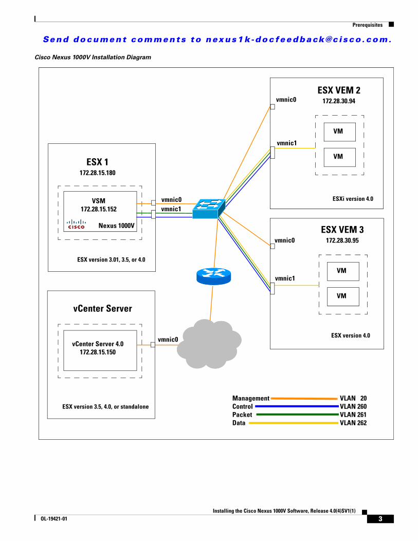
• You are familiar with the “Cisco Nexus 1000V Installation Diagram” section on page 3 illustrating a sample Cisco Nexus 1000V installation.
Note In this example we have used ESXi 4.0 for the host. The VEM install instructions are the same for ESX 4.0.
2Installing the Cisco Nexus 1000V Software, Release 4.0(4)SV1(1)
OL-19421-01
Send document comments to nexus1k -doc feedback@c i sco .com.
Prerequisites
Cisco Nexus 1000V Installation Diagram
ESX VEM 2172.28.30.94
VM
VM
ESXi version 4.0
vmnic1
vmnic0
ESX VEM 3172.28.30.95
VM
VM
ESX version 4.0
vmnic1
vmnic0
ESX 1172.28.15.180
VSM172.28.15.152
ESX version 3.01, 3.5, or 4.0
vmnic1vmnic0
vCenter Server 4.0172.28.15.150
ESX version 3.5, 4.0, or standalone
vmnic0
Nexus 1000V
Management Control Packet Data
VLAN 20VLAN 260VLAN 261VLAN 262
vCenter Server
3Installing the Cisco Nexus 1000V Software, Release 4.0(4)SV1(1)
OL-19421-01
Send document comments to nexus1k -doc feedback@c i sco .com.
Flow Chart: Installing the Cisco Nexus 1000V Software
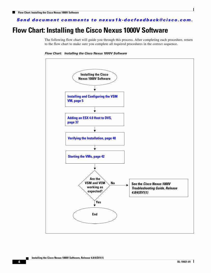
Flow Chart: Installing the Cisco Nexus 1000V SoftwareThe following flow chart will guide you through this process. After completing each procedure, return to the flow chart to make sure you complete all required procedures in the correct sequence.
Flow Chart: Installing the Cisco Nexus 1000V Software
Installing the Cisco Nexus 1000V Software
Installing and Configuring the VSM VM, page 5
Adding an ESX 4.0 Host to DVS, page 37
Verifying the Installation, page 40
Starting the VMs, page 42
Are the VSM and VEM
working as expected?
See the Cisco Nexus 1000V Troubleshooting Guide, Release 4.0(4)SV1(1)
Yes
No
EndEnd
4Installing the Cisco Nexus 1000V Software, Release 4.0(4)SV1(1)
OL-19421-01
Send document comments to nexus1k -doc feedback@c i sco .com.
Installing and Configuring the VSM VM
Installing and Configuring the VSM VMUse the procedures in this section to install and configure the VSM VM.
BEFORE YOU BEGIN
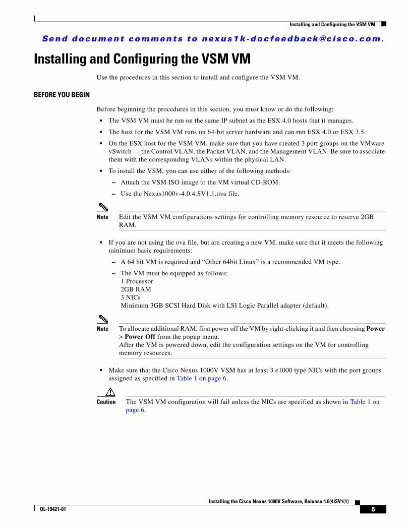
Before beginning the procedures in this section, you must know or do the following:
• The VSM VM must be run on the same IP subnet as the ESX 4.0 hosts that it manages.
• The host for the VSM VM runs on 64-bit server hardware and can run ESX 4.0 or ESX 3.5.
• On the ESX host for the VSM VM, make sure that you have created 3 port groups on the VMware vSwitch — the Control VLAN, the Packet VLAN, and the Management VLAN. Be sure to associate them with the corresponding VLANs within the physical LAN.
• To install the VSM, you can use either of the following methods:
– Attach the VSM ISO image to the VM virtual CD-ROM.
– Use the Nexus1000v-4.0.4.SV1.1.ova file.
Note Edit the VSM VM configurations settings for controlling memory resource to reserve 2GB RAM.
• If you are not using the ova file, but are creating a new VM, make sure that it meets the following minimum basic requirements:
– A 64 bit VM is required and “Other 64bit Linux” is a recommended VM type.
– The VM must be equipped as follows:1 Processor2GB RAM3 NICsMinimum 3GB SCSI Hard Disk with LSI Logic Parallel adapter (default).
Note To allocate additional RAM, first power off the VM by right-clicking it and then choosing Power > Power Off from the popup menu.After the VM is powered down, edit the configuration settings on the VM for controlling memory resources.
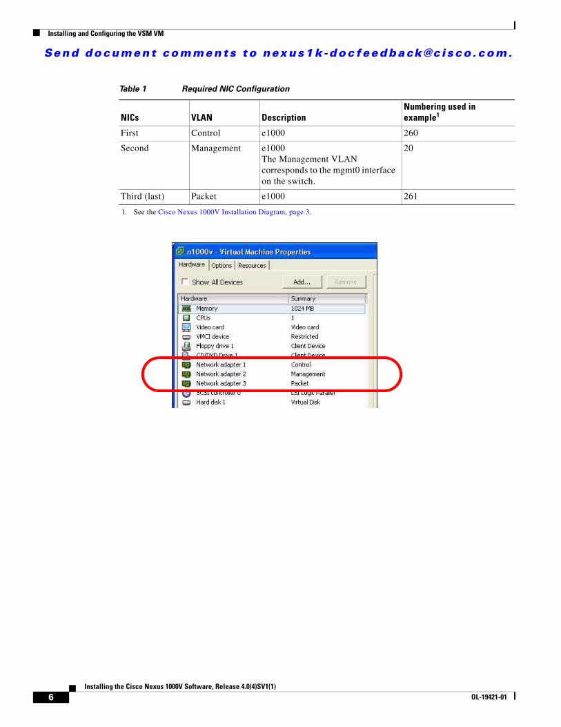
• Make sure that the Cisco Nexus 1000V VSM has at least 3 e1000 type NICs with the port groups assigned as specified in Table 1 on page 6.
Caution The VSM VM configuration will fail unless the NICs are specified as shown in Table 1 on page 6.
5Installing the Cisco Nexus 1000V Software, Release 4.0(4)SV1(1)
OL-19421-01
Send document comments to nexus1k -doc feedback@c i sco .com.
Installing and Configuring the VSM VM
Table 1 Required NIC Configuration
NICs VLAN DescriptionNumbering used in example1
1. See the Cisco Nexus 1000V Installation Diagram, page 3.
First Control e1000 260
Second Management e1000The Management VLAN corresponds to the mgmt0 interface on the switch.
20
Third (last) Packet e1000 261
6Installing the Cisco Nexus 1000V Software, Release 4.0(4)SV1(1)
OL-19421-01
Send document comments to nexus1k -doc feedback@c i sco .com.
Installing and Configuring the VSM VM
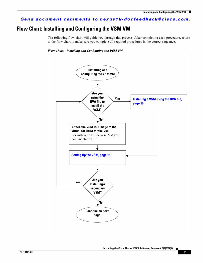
Flow Chart: Installing and Configuring the VSM VMThe following flow chart will guide you through this process. After completing each procedure, return to the flow chart to make sure you complete all required procedures in the correct sequence.
Flow Chart: Installing and Configuring the VSM VM
Installing and Configuring the VSM VM
Setting Up the VSM, page 15
Continue on next page
Attach the VSM ISO image to the virtual CD-ROM for the VM.For instructions, see your VMware documentation.
Are you using the
OVA file to install the
VSM?
Yes
No
Installing a VSM using the OVA file, page 10
Are you Installing a secondary
VSM?
Yes
No
7Installing the Cisco Nexus 1000V Software, Release 4.0(4)SV1(1)
OL-19421-01
Send document comments to nexus1k -doc feedback@c i sco .com.
Installing and Configuring the VSM VM
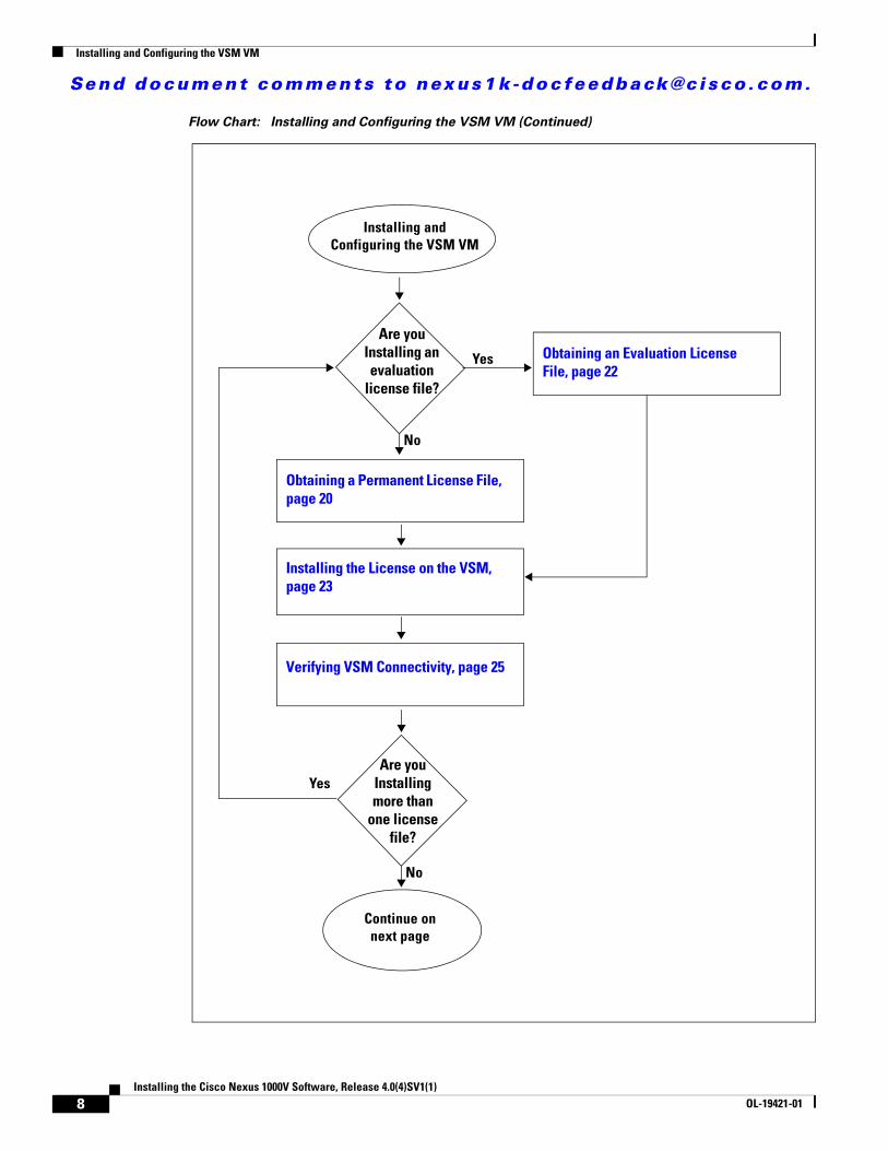
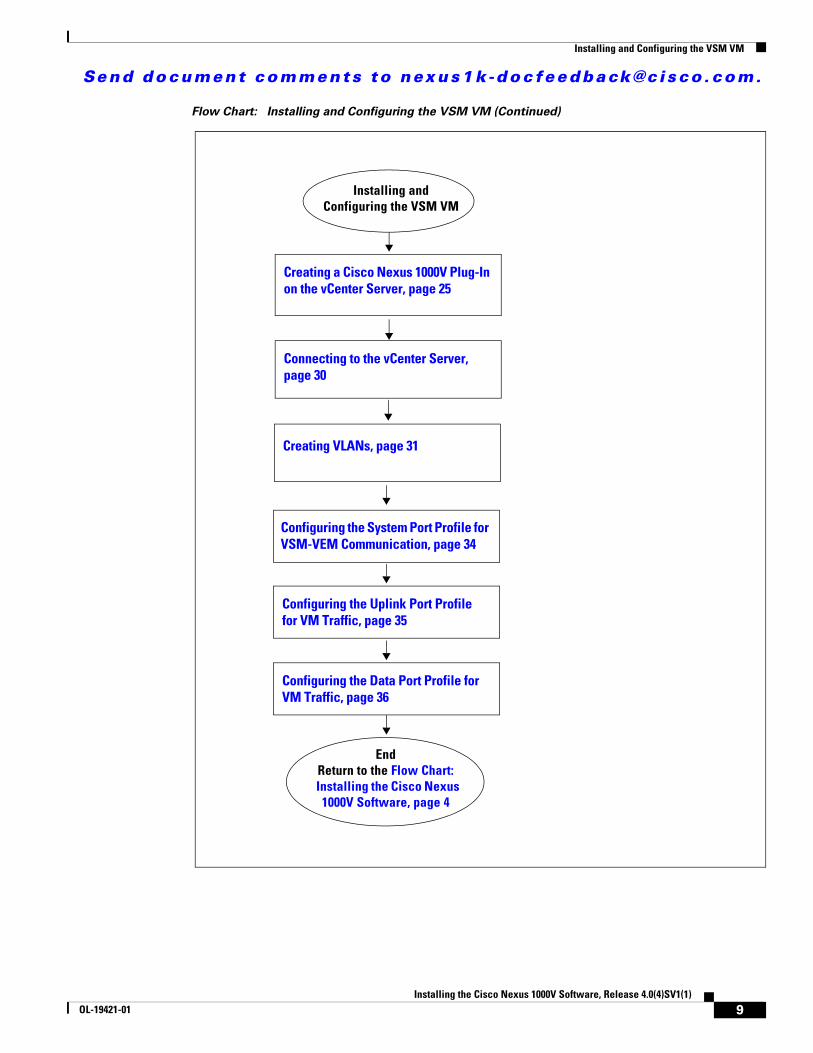
Flow Chart: Installing and Configuring the VSM VM (Continued)
Installing and Configuring the VSM VM
Continue on next page
Installing the License on the VSM, page 23
Obtaining a Permanent License File, page 20
Verifying VSM Connectivity, page 25
Are you Installing an evaluation
license file?
Yes
No
Obtaining an Evaluation License File, page 22
Are you Installing more than
one license file?
Yes
No
8Installing the Cisco Nexus 1000V Software, Release 4.0(4)SV1(1)
OL-19421-01
Send document comments to nexus1k -doc feedback@c i sco .com.
Installing and Configuring the VSM VM
Flow Chart: Installing and Configuring the VSM VM (Continued)
Installing and Configuring the VSM VM
EndReturn to the Flow Chart: Installing the Cisco Nexus 1000V Software, page 4
Configuring the Data Port Profile for VM Traffic, page 36
Configuring the Uplink Port Profile for VM Traffic, page 35
Configuring the System Port Profile for VSM-VEM Communication, page 34
Creating VLANs, page 31
Creating a Cisco Nexus 1000V Plug-In on the vCenter Server, page 25
Connecting to the vCenter Server, page 30
9Installing the Cisco Nexus 1000V Software, Release 4.0(4)SV1(1)
OL-19421-01
Send document comments to nexus1k -doc feedback@c i sco .com.
Installing and Configuring the VSM VM
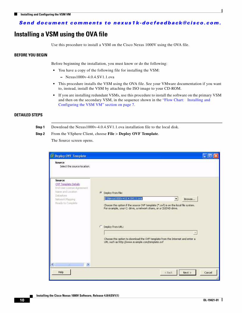
Installing a VSM using the OVA fileUse this procedure to install a VSM on the Cisco Nexus 1000V using the OVA file.
BEFORE YOU BEGIN
Before beginning the installation, you must know or do the following:
• You have a copy of the following file for installing the VSM:
– Nexus1000v-4.0.4.SV1.1.ova
• This procedure installs the VSM using the OVA file. See your VMware documentation if you want to, instead, install the VSM by attaching the ISO image to your CD-ROM.
• If you are installing redundant VSMs, use this procedure to install the software on the primary VSM and then on the secondary VSM, in the sequence shown in the “Flow Chart: Installing and Configuring the VSM VM” section on page 7.
DETAILED STEPS
Step 1 Download the Nexus1000v-4.0.4.SV1.1.ova installation file to the local disk.
Step 2 From the VSphere Client, choose File > Deploy OVF Template.
The Source screen opens.
10Installing the Cisco Nexus 1000V Software, Release 4.0(4)SV1(1)
OL-19421-01
Send document comments to nexus1k -doc feedback@c i sco .com.
Installing and Configuring the VSM VM
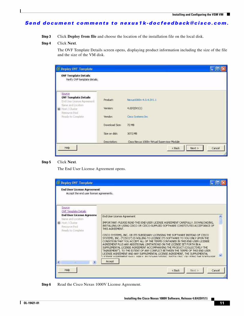
Step 3 Click Deploy from file and choose the location of the installation file on the local disk.
Step 4 Click Next.
The OVF Template Details screen opens, displaying product information including the size of the file and the size of the VM disk.
Step 5 Click Next.
The End User License Agreement opens.
Step 6 Read the Cisco Nexus 1000V License Agreement.
11Installing the Cisco Nexus 1000V Software, Release 4.0(4)SV1(1)
OL-19421-01

Send document comments to nexus1k -doc feedback@c i sco .com.
Installing and Configuring the VSM VM
Step 7 Click Accept and then click Next.
The Name and Location screen Opens.
Step 8 In the Name field, add a name for the VSM that is unique within the inventory folder and less than 80 characters in length. Then click Next.
The Host or Cluster screen opens.
Step 9 Choose the host where this VSM will be installed. Then click Next.
12Installing the Cisco Nexus 1000V Software, Release 4.0(4)SV1(1)
OL-19421-01
Send document comments to nexus1k -doc feedback@c i sco .com.
Installing and Configuring the VSM VM
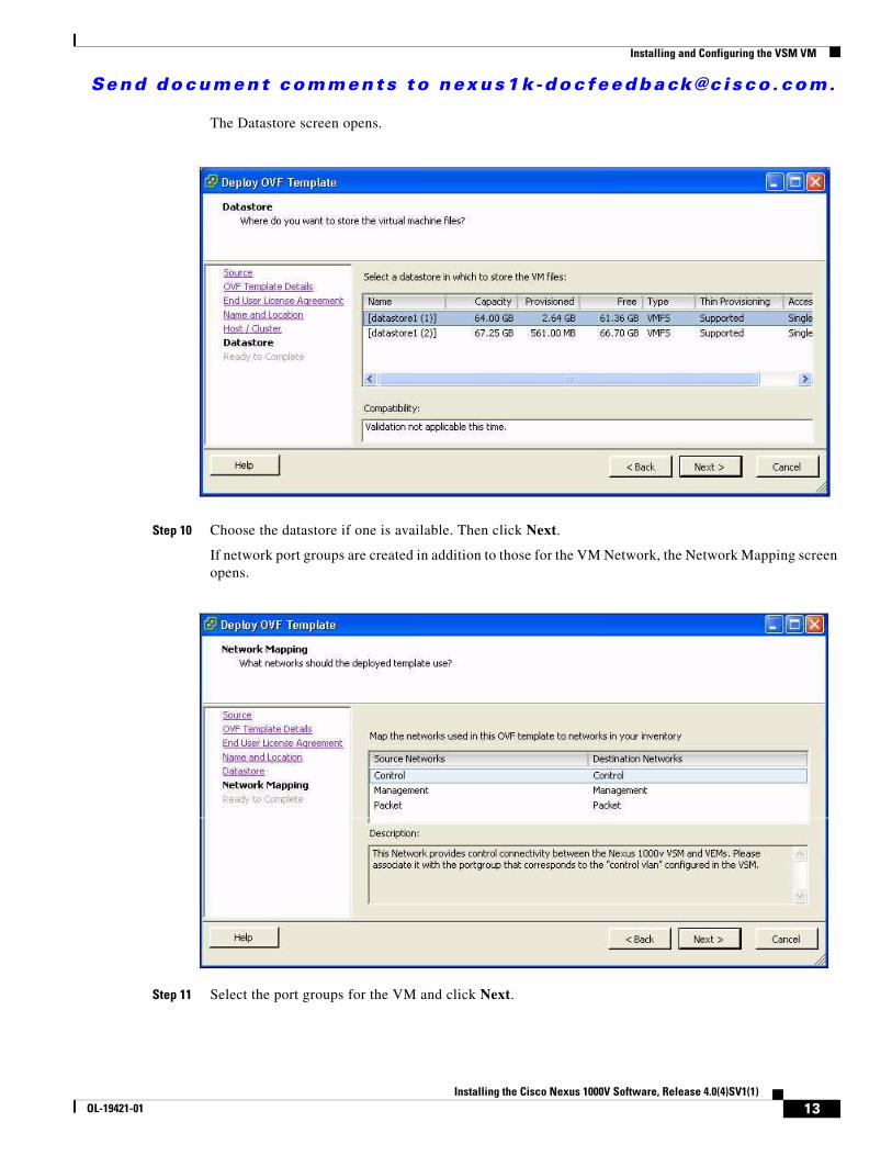
The Datastore screen opens.
Step 10 Choose the datastore if one is available. Then click Next.
If network port groups are created in addition to those for the VM Network, the Network Mapping screen opens.
Step 11 Select the port groups for the VM and click Next.
13Installing the Cisco Nexus 1000V Software, Release 4.0(4)SV1(1)
OL-19421-01
Send document comments to nexus1k -doc feedback@c i sco .com.
Installing and Configuring the VSM VM
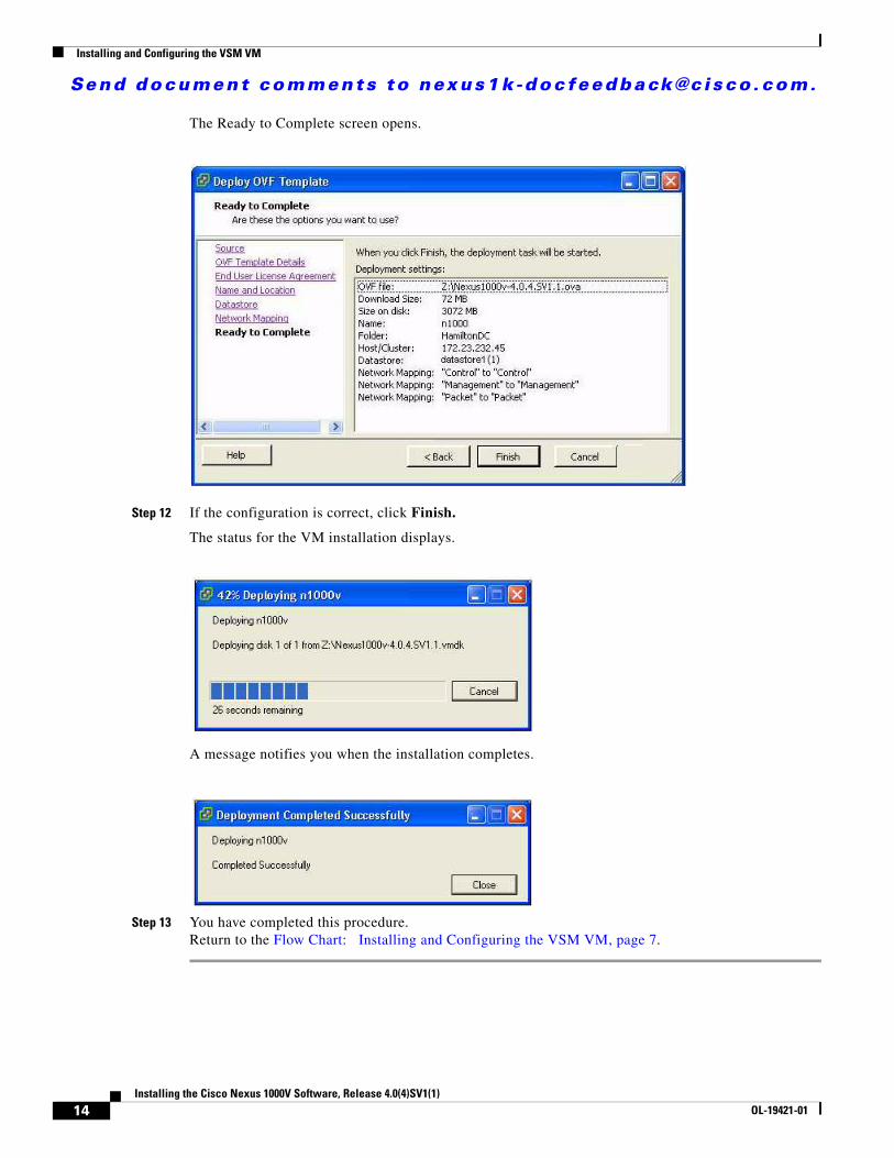
The Ready to Complete screen opens.
Step 12 If the configuration is correct, click Finish.
The status for the VM installation displays.
A message notifies you when the installation completes.
Step 13 You have completed this procedure.Return to the Flow Chart: Installing and Configuring the VSM VM, page 7.
14Installing the Cisco Nexus 1000V Software, Release 4.0(4)SV1(1)
OL-19421-01
Send document comments to nexus1k -doc feedback@c i sco .com.
Installing and Configuring the VSM VM
Setting Up the VSMUse this procedure to set up and save the VSM management access configuration.
BEFORE YOU BEGIN
Before beginning this procedure, you must know or do the following:
• This procedure requires that the VSM image is already installed. You can install the VSM by attaching the ISO image to your CD-ROM using the VMware documentation; or by using the “Installing a VSM using the OVA file” procedure on page 10.
• This procedure requires you to create an administrator password. Use the following password strength guidelines:
– At least eight characters in length
– Avoid using consecutive characters (such as "abcd")
– Avoid using repeating characters (such as "aaabbb")
– No dictionary words
– No proper names
– Contains both uppercase and lowercase characters
– Contains numbers
Note All alphanumeric characters and symbols on a standard US keyboard are allowed except for these three: $ \ ?
• You have the following networking information available:
– VSM VM mgmt0 IP address and netmask
– Default gateway IP address
• Cisco highly recommends that you run the VSM in an HA environment. For more information about configuring HA, see the Cisco Nexus 1000V High Availability and Redundancy Reference, Release 4.0(4)SV1(1).
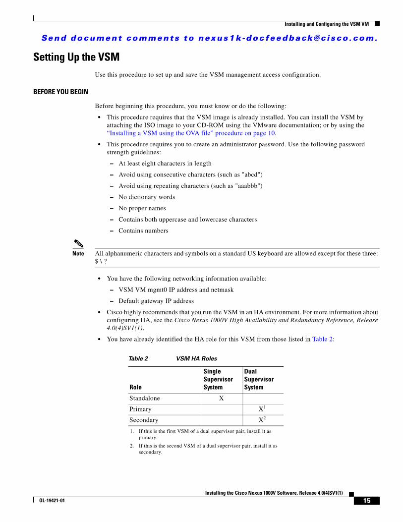
• You have already identified the HA role for this VSM from those listed in Table 2:
Table 2 VSM HA Roles
Role
Single Supervisor System
Dual Supervisor System
Standalone X
Primary X1
1. If this is the first VSM of a dual supervisor pair, install it as primary.
Secondary X2
2. If this is the second VSM of a dual supervisor pair, install it as secondary.
15Installing the Cisco Nexus 1000V Software, Release 4.0(4)SV1(1)
OL-19421-01
Send document comments to nexus1k -doc feedback@c i sco .com.
Installing and Configuring the VSM VM
For more information about HA roles, see the Cisco Nexus 1000V High Availability and Redundancy Reference, Release 4.0(4)SV1(1).
• Although primary and secondary VSMs can reside in the same host, to improve redundancy, install them in separate hosts and, if possible, connected to different upstream switches. For other recommendations, see the “Implementation Guidelines” section on page 42.
• You have the following Cisco Nexus 1000V domain information:
– Control VLAN ID
– Packet VLAN ID
– Domain ID
DETAILED STEPS
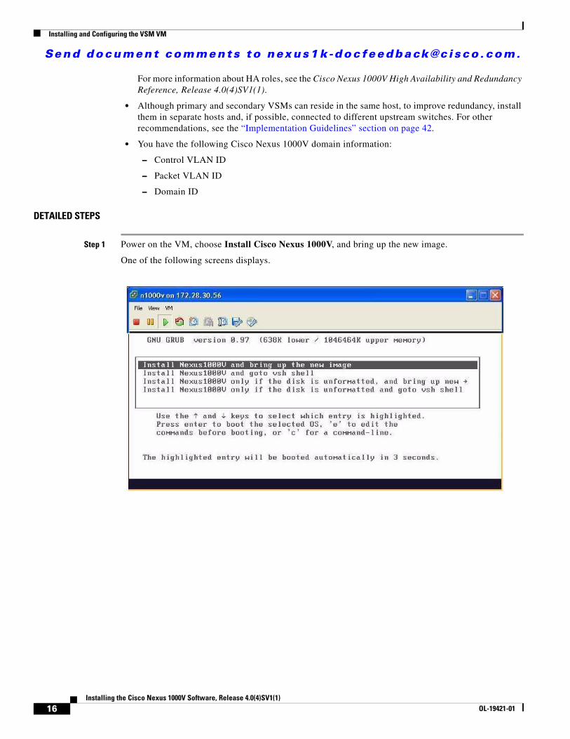
Step 1 Power on the VM, choose Install Cisco Nexus 1000V, and bring up the new image.
One of the following screens displays.
16Installing the Cisco Nexus 1000V Software, Release 4.0(4)SV1(1)
OL-19421-01
Send document comments to nexus1k -doc feedback@c i sco .com.
Installing and Configuring the VSM VM
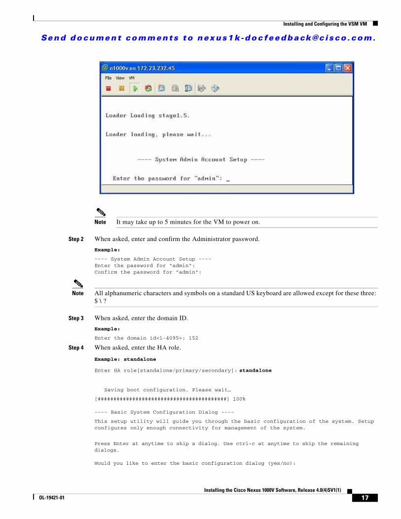
Note It may take up to 5 minutes for the VM to power on.
Step 2 When asked, enter and confirm the Administrator password.
Example:
---- System Admin Account Setup ----Enter the password for "admin": Confirm the password for "admin":
Note All alphanumeric characters and symbols on a standard US keyboard are allowed except for these three: $ \ ?
Step 3 When asked, enter the domain ID.
Example:
Enter the domain id<1-4095>: 152
Step 4 When asked, enter the HA role.
Example: standalone
Enter HA role[standalone/primary/secondary]: standalone
Saving boot configuration. Please wait…
[#########################################] 100%
---- Basic System Configuration Dialog ----
This setup utility will guide you through the basic configuration of the system. Setup configures only enough connectivity for management of the system.
Press Enter at anytime to skip a dialog. Use ctrl-c at anytime to skip the remaining dialogs.
Would you like to enter the basic configuration dialog (yes/no):
17Installing the Cisco Nexus 1000V Software, Release 4.0(4)SV1(1)
OL-19421-01
Send document comments to nexus1k -doc feedback@c i sco .com.
Installing and Configuring the VSM VM
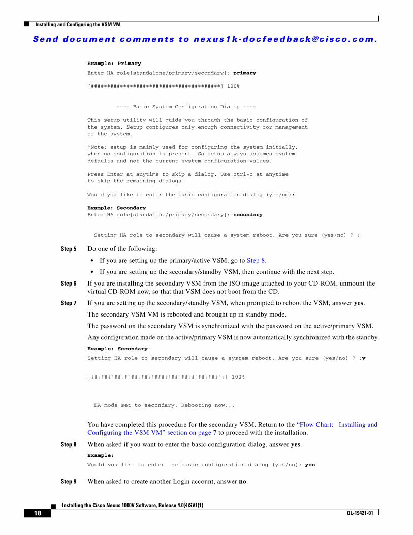
Example: Primary
Enter HA role[standalone/primary/secondary]: primary
[########################################] 100%
---- Basic System Configuration Dialog ----
This setup utility will guide you through the basic configuration ofthe system. Setup configures only enough connectivity for managementof the system.
*Note: setup is mainly used for configuring the system initially,when no configuration is present. So setup always assumes systemdefaults and not the current system configuration values.
Press Enter at anytime to skip a dialog. Use ctrl-c at anytimeto skip the remaining dialogs.
Would you like to enter the basic configuration dialog (yes/no):
Example: SecondaryEnter HA role[standalone/primary/secondary]: secondary
Setting HA role to secondary will cause a system reboot. Are you sure (yes/no) ? :
Step 5 Do one of the following:
• If you are setting up the primary/active VSM, go to Step 8.
• If you are setting up the secondary/standby VSM, then continue with the next step.
Step 6 If you are installing the secondary VSM from the ISO image attached to your CD-ROM, unmount the virtual CD-ROM now, so that that VSM does not boot from the CD.
Step 7 If you are setting up the secondary/standby VSM, when prompted to reboot the VSM, answer yes.
The secondary VSM VM is rebooted and brought up in standby mode.
The password on the secondary VSM is synchronized with the password on the active/primary VSM.
Any configuration made on the active/primary VSM is now automatically synchronized with the standby.
Example: Secondary
Setting HA role to secondary will cause a system reboot. Are you sure (yes/no) ? :y
[########################################] 100%
HA mode set to secondary. Rebooting now...
You have completed this procedure for the secondary VSM. Return to the “Flow Chart: Installing and Configuring the VSM VM” section on page 7 to proceed with the installation.
Step 8 When asked if you want to enter the basic configuration dialog, answer yes.
Example:
Would you like to enter the basic configuration dialog (yes/no): yes
Step 9 When asked to create another Login account, answer no.
18Installing the Cisco Nexus 1000V Software, Release 4.0(4)SV1(1)
OL-19421-01
Send document comments to nexus1k -doc feedback@c i sco .com.
Installing and Configuring the VSM VM
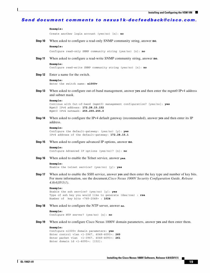
Example:
Create another login account (yes/no) [n]: no
Step 10 When asked to configure a read-only SNMP community string, answer no.
Example:
Configure read-only SNMP community string (yes/no) [n]: no
Step 11 When asked to configure a read-write SNMP community string, answer no.
Example:Configure read-write SNMP community string (yes/no) [n]: no
Step 12 Enter a name for the switch.
Example:Enter the switch name: n1000v
Step 13 When asked to configure out-of-band management, answer yes and then enter the mgmt0 IPv4 address and subnet mask.
Example:Continue with Out-of-band (mgmt0) management configuration? [yes/no]: yesMgmt0 IPv4 address: 172.28.15.152Mgmt0 IPv4 netmask: 255.255.255.0
Step 14 When asked to configure the IPv4 default gateway (recommended), answer yes and then enter its IP address.
Example:Configure the default-gateway: (yes/no) [y]: yes IPv4 address of the default-gateway: 172.28.15.1
Step 15 When asked to configure advanced IP options, answer no.
Example:Configure Advanced IP options (yes/no)? [n]: no
Step 16 When asked to enable the Telnet service, answer yes.
Example:Enable the telnet service? (yes/no) [y]: yes
Step 17 When asked to enable the SSH service, answer yes and then enter the key type and number of key bits.For more information, see the document,Cisco Nexus 1000V Security Configuration Guide, Release 4.0(4)SV1(1).
Example:Enable the ssh service? (yes/no) [y]: yesType of ssh key you would like to generate (dsa/rsa) : rsaNumber of key bits <768-2048> : 1024
Step 18 When asked to configure the NTP server, answer no.
Example:Configure NTP server? (yes/no) [n]: no
Step 19 When asked to configure Cisco Nexus 1000V domain parameters, answer yes and then enter them.
Example:Configure n1000v domain parameters: yesEnter control vlan <1-3967, 4048-4093>: 260Enter packet vlan <1-3967, 4048-4093>: 261Enter domain id <1-4095>: [152]:
19Installing the Cisco Nexus 1000V Software, Release 4.0(4)SV1(1)
OL-19421-01
Send document comments to nexus1k -doc feedback@c i sco .com.
Installing and Configuring the VSM VM
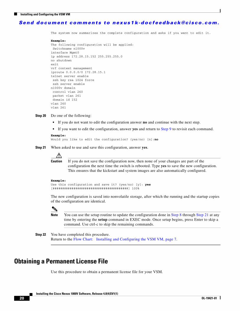
The system now summarizes the complete configuration and asks if you want to edit it.
Example:The following configuration will be applied: Switchname n1000vinterface Mgmt0ip address 172.28.15.152 255.255.255.0no shutdownexitvrf context management iproute 0.0.0.0/0 172.28.15.1telnet server enable ssh key rsa 1024 force ssh server enablen1000v domain control vlan 260 packet vlan 261 domain id 152vlan 260vlan 261
Step 20 Do one of the following:
• If you do not want to edit the configuration answer no and continue with the next step.
• If you want to edit the configuration, answer yes and return to Step 9 to revisit each command.
Example:Would you like to edit the configuration? (yes/no) [n]:no
Step 21 When asked to use and save this configuration, answer yes.
Caution If you do not save the configuration now, then none of your changes are part of the configuration the next time the switch is rebooted. Type yes to save the new configuration. This ensures that the kickstart and system images are also automatically configured.
Example:Use this configuration and save it? (yes/no) [y]: yes[########################################] 100%
The new configuration is saved into nonvolatile storage, after which the running and the startup copies of the configuration are identical.
Note You can use the setup routine to update the configuration done in Step 8 through Step 21 at any time by entering the setup command in EXEC mode. Once setup begins, press Enter to skip a command. Use ctrl-c to skip the remaining commands.
Step 22 You have completed this procedure. Return to the Flow Chart: Installing and Configuring the VSM VM, page 7.
Obtaining a Permanent License File Use this procedure to obtain a permanent license file for your VSM.
20Installing the Cisco Nexus 1000V Software, Release 4.0(4)SV1(1)
OL-19421-01
Send document comments to nexus1k -doc feedback@c i sco .com.
Installing and Configuring the VSM VM
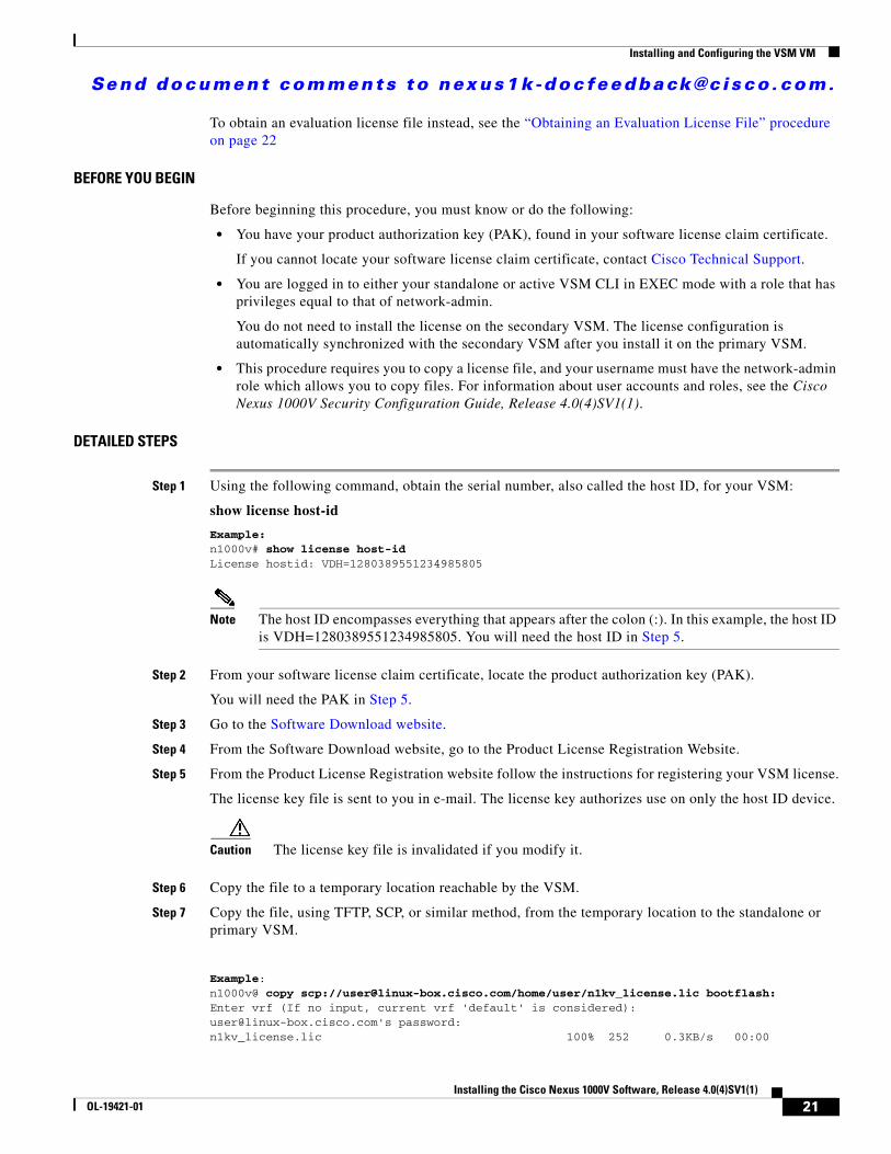
To obtain an evaluation license file instead, see the “Obtaining an Evaluation License File” procedure on page 22
BEFORE YOU BEGIN
Before beginning this procedure, you must know or do the following:
• You have your product authorization key (PAK), found in your software license claim certificate.
If you cannot locate your software license claim certificate, contact Cisco Technical Support.
• You are logged in to either your standalone or active VSM CLI in EXEC mode with a role that has privileges equal to that of network-admin.
You do not need to install the license on the secondary VSM. The license configuration is automatically synchronized with the secondary VSM after you install it on the primary VSM.
• This procedure requires you to copy a license file, and your username must have the network-admin role which allows you to copy files. For information about user accounts and roles, see the Cisco Nexus 1000V Security Configuration Guide, Release 4.0(4)SV1(1).
DETAILED STEPS
Step 1 Using the following command, obtain the serial number, also called the host ID, for your VSM:
show license host-id
Example:n1000v# show license host-idLicense hostid: VDH=1280389551234985805
Note The host ID encompasses everything that appears after the colon (:). In this example, the host ID is VDH=1280389551234985805. You will need the host ID in Step 5.
Step 2 From your software license claim certificate, locate the product authorization key (PAK).
You will need the PAK in Step 5.
Step 3 Go to the Software Download website.
Step 4 From the Software Download website, go to the Product License Registration Website.
Step 5 From the Product License Registration website follow the instructions for registering your VSM license.
The license key file is sent to you in e-mail. The license key authorizes use on only the host ID device.
Caution The license key file is invalidated if you modify it.
Step 6 Copy the file to a temporary location reachable by the VSM.
Step 7 Copy the file, using TFTP, SCP, or similar method, from the temporary location to the standalone or primary VSM.
Example:n1000v@ copy scp://[email protected]/home/user/n1kv_license.lic bootflash:Enter vrf (If no input, current vrf 'default' is considered):[email protected]'s password:n1kv_license.lic 100% 252 0.3KB/s 00:00
21Installing the Cisco Nexus 1000V Software, Release 4.0(4)SV1(1)
OL-19421-01
Send document comments to nexus1k -doc feedback@c i sco .com.
Installing and Configuring the VSM VM
n1000v@
Step 8 You have completed this procedure. Return to the “Flow Chart: Installing and Configuring the VSM VM (Continued)” section on page 8.
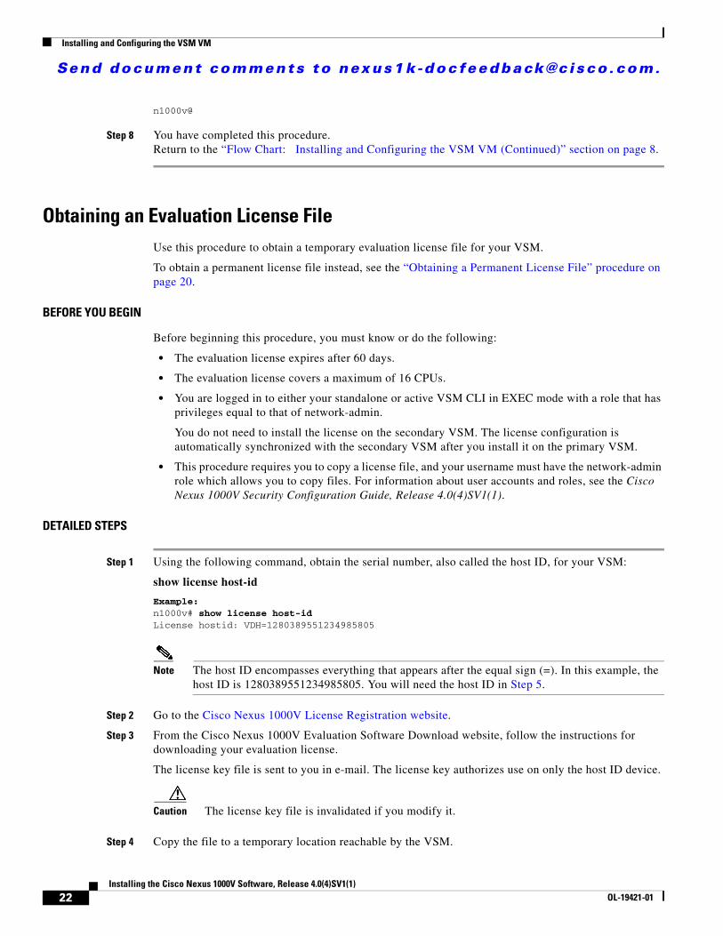
Obtaining an Evaluation License File Use this procedure to obtain a temporary evaluation license file for your VSM.
To obtain a permanent license file instead, see the “Obtaining a Permanent License File” procedure on page 20.
BEFORE YOU BEGIN
Before beginning this procedure, you must know or do the following:
• The evaluation license expires after 60 days.
• The evaluation license covers a maximum of 16 CPUs.
• You are logged in to either your standalone or active VSM CLI in EXEC mode with a role that has privileges equal to that of network-admin.
You do not need to install the license on the secondary VSM. The license configuration is automatically synchronized with the secondary VSM after you install it on the primary VSM.
• This procedure requires you to copy a license file, and your username must have the network-admin role which allows you to copy files. For information about user accounts and roles, see the Cisco Nexus 1000V Security Configuration Guide, Release 4.0(4)SV1(1).
DETAILED STEPS
Step 1 Using the following command, obtain the serial number, also called the host ID, for your VSM:
show license host-id
Example:n1000v# show license host-idLicense hostid: VDH=1280389551234985805
Note The host ID encompasses everything that appears after the equal sign (=). In this example, the host ID is 1280389551234985805. You will need the host ID in Step 5.
Step 2 Go to the Cisco Nexus 1000V License Registration website.
Step 3 From the Cisco Nexus 1000V Evaluation Software Download website, follow the instructions for downloading your evaluation license.
The license key file is sent to you in e-mail. The license key authorizes use on only the host ID device.
Caution The license key file is invalidated if you modify it.
Step 4 Copy the file to a temporary location reachable by the VSM.
22Installing the Cisco Nexus 1000V Software, Release 4.0(4)SV1(1)
OL-19421-01

Send document comments to nexus1k -doc feedback@c i sco .com.
Installing and Configuring the VSM VM
Step 5 Copy the file, using TFTP, SCP, or similar method, from the temporary location to the standalone or primary VSM.
Example:n1000v@ copy scp://[email protected]/home/user/n1kv_license.lic bootflash:Enter vrf (If no input, current vrf 'default' is considered):[email protected]'s password:n1kv_license.lic 100% 252 0.3KB/s 00:00
n1000v@
Step 6 You have completed this procedure. Return to the “Flow Chart: Installing and Configuring the VSM VM (Continued)” section on page 8.
Installing the License on the VSM Use this procedure to install the license on a standalone or primary VSM.
BEFORE YOU BEGIN
Before beginning this procedure, you must know or do the following:
• If your VSM has an Evaluation License already installed, you must unintsall it before installing a Permanent License. For more information, see the Uninstalling a License procedure in the Cisco Nexus 1000V License Configuration Guide, Release 4.0(4)SV1(1).
• This procedure installs the license from the license key file using the name license_file.lic. You can specify a different name.
• If you are installing multiple licenses for the same VSM, also called license stacking, make sure that each license key file name is unique.
• Repeat this procedure for each additional license file you are installing, or stacking, on the VSM.
• You are logged in to the standalone or active VSM console port.
You do not need to install the license on the secondary VSM. The license configuration is automatically synchronized with the secondary VSM after you install it on the primary VSM.
• This procedure requires you to copy a license file, and your username must have the network-admin role which allows you to copy files. For information about user accounts and roles, see the Cisco Nexus 1000V Security Configuration Guide, Release 4.0(4)SV1(1).
SUMMARY STEPS
1. install license bootflash: file_name
2. show license file file_name
3. show license usage NEXUS1000V_LAN_SERVICES_PKG
4. copy running-config startup-config
23Installing the Cisco Nexus 1000V Software, Release 4.0(4)SV1(1)
OL-19421-01

Send document comments to nexus1k -doc feedback@c i sco .com.
Installing and Configuring the VSM VM
DETAILED STEPS
Command Purpose
Step 1 install license bootflash: [filename]
Example:n1000v# install license bootflash:license_file.lic Installing license ..done n1000v#
From the active VSM console, installs the license.
Note If you specify a license file name, the file is installed with the specified name. Otherwise, the default file name is used.
The license is installed on the VSM and each VEM automatically acquires a license for every CPU socket.
Step 2 show license file file_name
Example:
n1000v# show license file license.licSERVER this_host ANYVENDOR ciscoINCREMENT NEXUS1000V_LAN_SERVICES_PKG cisco 1.0 permanent 1 \ HOSTID=VDH=1575337335122974806 \ NOTICE="<LicFileID>license.lic</LicFileID><LicLineID>0</LicLineID> \ <PAK>dummyPak</PAK>" SIGN=3AF5C2D26E1An1000v#
Verify the license installation by displaying the license configured for the VSM.
Step 3 show license usage NEXUS1000V_LAN_SERVICES_PKG
Example:n1000v# show license usage NEXUS1000V_LAN_SERVICES_PKGApplication-----------VEM 3 - Socket 1VEM 3 - Socket 2VEM 4 - Socket 1VEM 4 - Socket 2-----------
n1000v#
Verifies the license installation by displaying the CPU licenses in use on each VEM.
Step 4 copy running-config startup-config
Example:n1000v(config)# copy running-config startup-config
(Optional) Saves the running configuration persistently through reboots and restarts by copying it to the startup configuration.
Step 5 You have completed this procedure. Return to the Flow Chart: Installing and Configuring the VSM VM (Continued), page 8.
24Installing the Cisco Nexus 1000V Software, Release 4.0(4)SV1(1)
OL-19421-01
Send document comments to nexus1k -doc feedback@c i sco .com.
Installing and Configuring the VSM VM
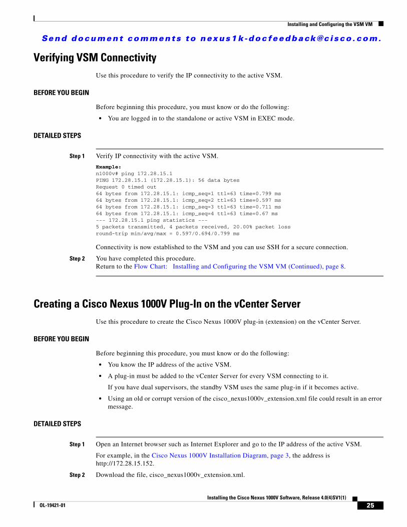
Verifying VSM ConnectivityUse this procedure to verify the IP connectivity to the active VSM.
BEFORE YOU BEGIN
Before beginning this procedure, you must know or do the following:
• You are logged in to the standalone or active VSM in EXEC mode.
DETAILED STEPS
Step 1 Verify IP connectivity with the active VSM.
Example:n1000v# ping 172.28.15.1 PING 172.28.15.1 (172.28.15.1): 56 data bytesRequest 0 timed out64 bytes from 172.28.15.1: icmp_seq=1 ttl=63 time=0.799 ms64 bytes from 172.28.15.1: icmp_seq=2 ttl=63 time=0.597 ms64 bytes from 172.28.15.1: icmp_seq=3 ttl=63 time=0.711 ms64 bytes from 172.28.15.1: icmp_seq=4 ttl=63 time=0.67 ms--- 172.28.15.1 ping statistics ---5 packets transmitted, 4 packets received, 20.00% packet lossround-trip min/avg/max = 0.597/0.694/0.799 ms
Connectivity is now established to the VSM and you can use SSH for a secure connection.
Step 2 You have completed this procedure. Return to the Flow Chart: Installing and Configuring the VSM VM (Continued), page 8.
Creating a Cisco Nexus 1000V Plug-In on the vCenter ServerUse this procedure to create the Cisco Nexus 1000V plug-in (extension) on the vCenter Server.
BEFORE YOU BEGIN
Before beginning this procedure, you must know or do the following:
• You know the IP address of the active VSM.
• A plug-in must be added to the vCenter Server for every VSM connecting to it.
If you have dual supervisors, the standby VSM uses the same plug-in if it becomes active.
• Using an old or corrupt version of the cisco_nexus1000v_extension.xml file could result in an error message.
DETAILED STEPS
Step 1 Open an Internet browser such as Internet Explorer and go to the IP address of the active VSM.
For example, in the Cisco Nexus 1000V Installation Diagram, page 3, the address is http://172.28.15.152.
Step 2 Download the file, cisco_nexus1000v_extension.xml.
25Installing the Cisco Nexus 1000V Software, Release 4.0(4)SV1(1)
OL-19421-01
Send document comments to nexus1k -doc feedback@c i sco .com.
Installing and Configuring the VSM VM
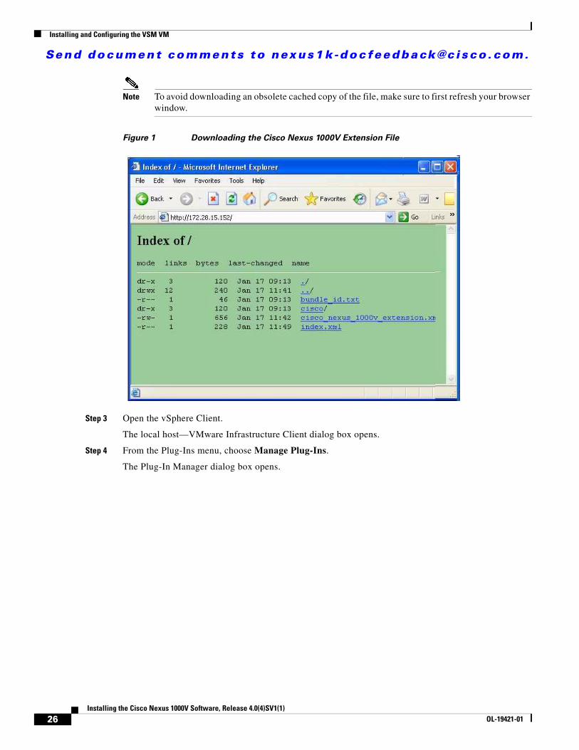
Note To avoid downloading an obsolete cached copy of the file, make sure to first refresh your browser window.
Figure 1 Downloading the Cisco Nexus 1000V Extension File
Step 3 Open the vSphere Client.
The local host—VMware Infrastructure Client dialog box opens.
Step 4 From the Plug-Ins menu, choose Manage Plug-Ins.
The Plug-In Manager dialog box opens.
26Installing the Cisco Nexus 1000V Software, Release 4.0(4)SV1(1)
OL-19421-01
Send document comments to nexus1k -doc feedback@c i sco .com.
Installing and Configuring the VSM VM
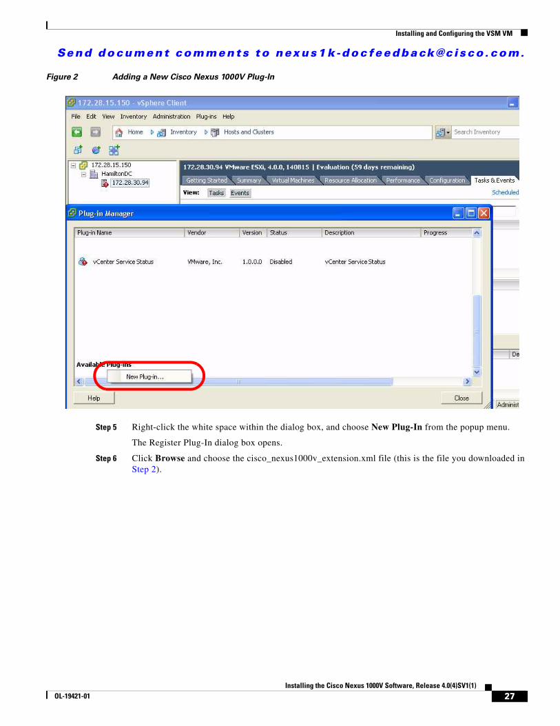
Figure 2 Adding a New Cisco Nexus 1000V Plug-In
Step 5 Right-click the white space within the dialog box, and choose New Plug-In from the popup menu.
The Register Plug-In dialog box opens.
Step 6 Click Browse and choose the cisco_nexus1000v_extension.xml file (this is the file you downloaded in Step 2).
27Installing the Cisco Nexus 1000V Software, Release 4.0(4)SV1(1)
OL-19421-01
Send document comments to nexus1k -doc feedback@c i sco .com.
Installing and Configuring the VSM VM
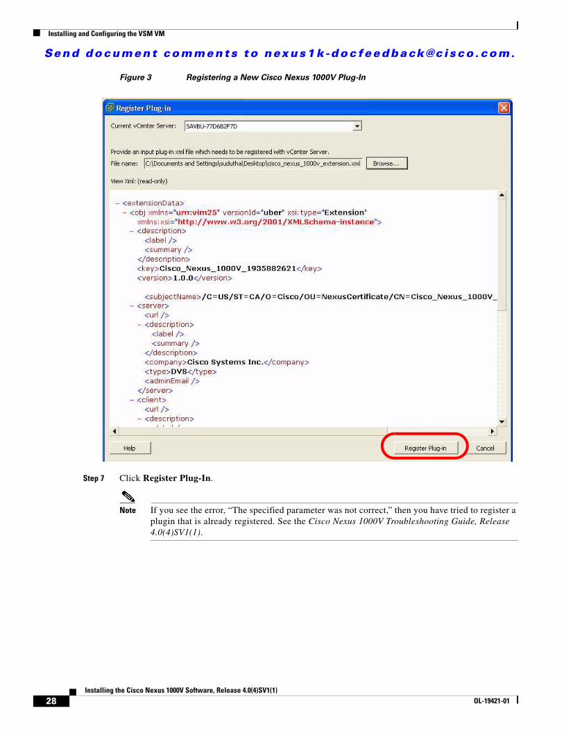
Figure 3 Registering a New Cisco Nexus 1000V Plug-In
Step 7 Click Register Plug-In.
Note If you see the error, “The specified parameter was not correct,” then you have tried to register a plugin that is already registered. See the Cisco Nexus 1000V Troubleshooting Guide, Release 4.0(4)SV1(1).
28Installing the Cisco Nexus 1000V Software, Release 4.0(4)SV1(1)
OL-19421-01
Send document comments to nexus1k -doc feedback@c i sco .com.
Installing and Configuring the VSM VM
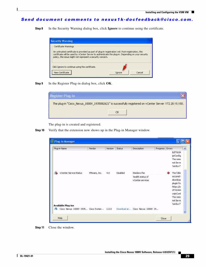
Step 8 In the Security Warning dialog box, click Ignore to continue using the certificate.
Step 9 In the Register Plug-in dialog box, click OK.
The plug-in is created and registered.
Step 10 Verify that the extension now shows up in the Plug-in Manager window.
Step 11 Close the window.
29Installing the Cisco Nexus 1000V Software, Release 4.0(4)SV1(1)
OL-19421-01
Send document comments to nexus1k -doc feedback@c i sco .com.
Installing and Configuring the VSM VM
Step 12 You have completed this procedure. Return to the Flow Chart: Installing and Configuring the VSM VM (Continued), page 9.
Connecting to the vCenter ServerUse this procedure to configure the connection between the VSM and the vCenter Server and then save the configuration in persistent memory across reboots and restarts.
BEFORE YOU BEGIN
Before beginning this procedure, you must know or do the following:
• You are logged in to the standalone or active VSM in EXEC mode.
• The extension for the Cisco Nexus 1000V is already registered as a plug-in on the vCenter Server.
• You know the datacenter name, which is case-sensitive.
• The datacenter already exists on the vCenter Server.
• You know the vCenter Server server IP address.
DETAILED STEPS
Step 1 In Server Virtualization Switch (SVS) Connection Configuration mode, set up your connection to the vCenter Server using the following command sequence.
Example:n1000v# config tn1000v(config)# svs connection VCn1000v((config-svs-conn)# vmware dvs datacenter-name HamiltonDCn1000v((config-svs-conn)# protocol vmware-vimn1000v((config-svs-conn)# remote ip address 172.28.15.150
Step 2 Connect to the vCenter Server.
Example:n1000v# config tn1000v(config)# svs connection VCn1000v(config-svs-conn)# connect n1000v(config-svs-conn)#
The connection is confirmed. A Cisco Nexus 1000V DVS is created on vCenter Server and is visible through vSphere Client under Inventory > Networking.
Note It may take up to 10 seconds to connect the first time.
Step 3 Verify the connection.
Example:n1000v# show svs connections
connection VC: hostname: 172.28.15.150 protocol: vmware-vim https certificate: default
30Installing the Cisco Nexus 1000V Software, Release 4.0(4)SV1(1)
OL-19421-01
Send document comments to nexus1k -doc feedback@c i sco .com.
Installing and Configuring the VSM VM
datacenter name: HamiltonDC DVS uuid: 6d fd 37 50 37 45 05 64-b9 a4 90 4e 66 eb 8c f5 config status: Enabled operational status: Connected
Step 4 Save the connection setup in the startup configuration.
Example:n1000v(config-svs-conn)# copy run start[########################################] 100%n1000v(config-svs-conn)#
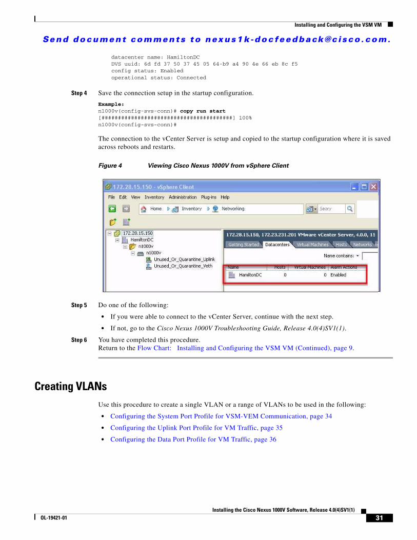
The connection to the vCenter Server is setup and copied to the startup configuration where it is saved across reboots and restarts.
Figure 4 Viewing Cisco Nexus 1000V from vSphere Client
Step 5 Do one of the following:
• If you were able to connect to the vCenter Server, continue with the next step.
• If not, go to the Cisco Nexus 1000V Troubleshooting Guide, Release 4.0(4)SV1(1).
Step 6 You have completed this procedure. Return to the Flow Chart: Installing and Configuring the VSM VM (Continued), page 9.
Creating VLANsUse this procedure to create a single VLAN or a range of VLANs to be used in the following:
• Configuring the System Port Profile for VSM-VEM Communication, page 34
• Configuring the Uplink Port Profile for VM Traffic, page 35
• Configuring the Data Port Profile for VM Traffic, page 36
31Installing the Cisco Nexus 1000V Software, Release 4.0(4)SV1(1)
OL-19421-01

Send document comments to nexus1k -doc feedback@c i sco .com.
Installing and Configuring the VSM VM
BEFORE YOU BEGIN
Before beginning this procedure, you must know or do the following:
Note All interfaces and all ports configured as switchports are in VLAN 1 by default.
• You are logged in to the CLI in EXEC mode.
• In accordance with the IEEE 802.1Q standard, up to 4094 VLANs (numbered 1-4094) are supported in Cisco Nexus 1000V, and are organized as shown in the following table.
• VLAN ranges used for control and packet port groups must be allowed on the upstream switch.
• Newly-created VLANs remain unused until Layer 2 ports are assigned to them.
• For information about the following, see the Cisco Nexus 1000V Interface Configuration Guide, Release 4.0(4)SV1(1).
– Assigning Layer 2 interfaces to VLANs (access or trunk ports).
– Configuring ports as VLAN access or trunk ports and assigning ports to VLANs.
• For more information about configuring VLANs, see the Cisco Nexus 1000V Layer 2 Switching Configuration Guide, Release 4.0(4)SV1(1).
SUMMARY STEPS
1. config t
2. vlan {vlan-id | vlan-range}
3. show vlan id <vlan-id>
4. copy running-config startup-config
VLAN Numbers Range Usage
1 Normal Cisco Nexus 1000V default. You can use this VLAN, but you cannot modify or delete it.
2–1005 Normal You can create, use, modify, and delete these VLANs.
1006-4094 Extended You can create, name, and use these VLANs. You cannot change the following parameters:
• State is always active.
• VLAN is always enabled. You cannot shut down these VLANs.
Note The extended system ID is always automatically enabled.
3968-4047 and 4094
Internally allocated
You cannot use, create, delete, or modify these VLANs. You can display these VLANs.
Cisco Nexus 1000V allocates these 80 VLANs, plus VLAN 4094, for features, like diagnostics, that use internal VLANs for their operation.
32Installing the Cisco Nexus 1000V Software, Release 4.0(4)SV1(1)
OL-19421-01
Send document comments to nexus1k -doc feedback@c i sco .com.
Installing and Configuring the VSM VM
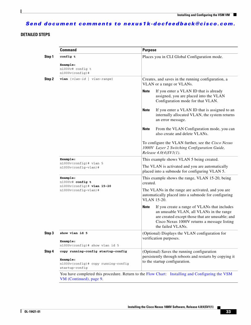
DETAILED STEPS
Command Purpose
Step 1 config t
Example:n1000v# config tn1000v(config)#
Places you in CLI Global Configuration mode.
Step 2 vlan {vlan-id | vlan-range} Creates, and saves in the running configuration, a VLAN or a range or VLANs.
Note If you enter a VLAN ID that is already assigned, you are placed into the VLAN Configuration mode for that VLAN.
Note If you enter a VLAN ID that is assigned to an internally allocated VLAN, the system returns an error message.
Note From the VLAN Configuration mode, you can also create and delete VLANs.
To configure the VLAN further, see the Cisco Nexus 1000V Layer 2 Switching Configuration Guide, Release 4.0(4)SV1(1).
Example:n1000v(config)# vlan 5n1000v(config-vlan)#
This example shows VLAN 5 being created.
The VLAN is activated and you are automatically placed into a submode for configuring VLAN 5.
Example:n1000v# config t n1000v(config)# vlan 15-20n1000v(config-vlan)#
This example shows the range, VLAN 15-20, being created.
The VLANs in the range are activated, and you are automatically placed into a submode for configuring VLAN 15-20.
Note If you create a range of VLANs that includes an unusable VLAN, all VLANs in the range are created except those that are unusable; and Cisco Nexus 1000V returns a message listing the failed VLANs.
Step 3 show vlan id 5
Example:n1000v(config)# show vlan id 5
(Optional) Displays the VLAN configuration for verification purposes.
Step 4 copy running-config startup-config
Example:n1000v(config)# copy running-config startup-config
(Optional) Saves the running configuration persistently through reboots and restarts by copying it to the startup configuration.
You have completed this procedure. Return to the Flow Chart: Installing and Configuring the VSM VM (Continued), page 9.
33Installing the Cisco Nexus 1000V Software, Release 4.0(4)SV1(1)
OL-19421-01
Send document comments to nexus1k -doc feedback@c i sco .com.
Installing and Configuring the VSM VM
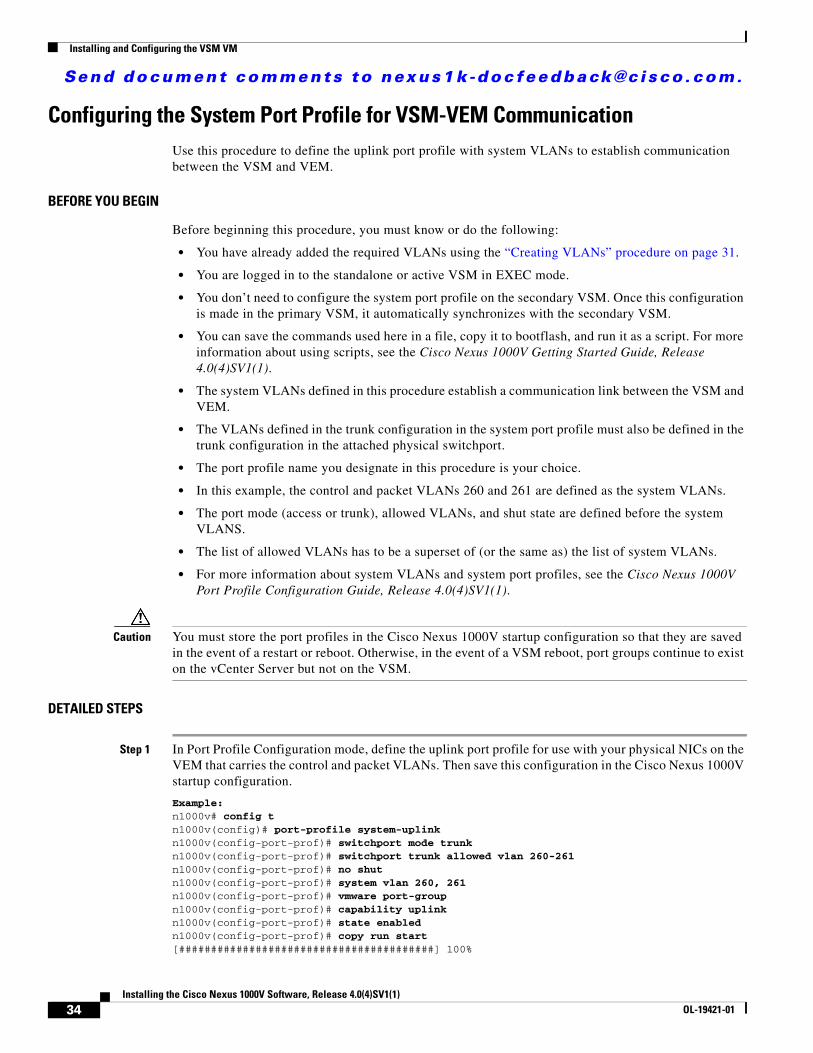
Configuring the System Port Profile for VSM-VEM Communication Use this procedure to define the uplink port profile with system VLANs to establish communication between the VSM and VEM.
BEFORE YOU BEGIN
Before beginning this procedure, you must know or do the following:
• You have already added the required VLANs using the “Creating VLANs” procedure on page 31.
• You are logged in to the standalone or active VSM in EXEC mode.
• You don’t need to configure the system port profile on the secondary VSM. Once this configuration is made in the primary VSM, it automatically synchronizes with the secondary VSM.
• You can save the commands used here in a file, copy it to bootflash, and run it as a script. For more information about using scripts, see the Cisco Nexus 1000V Getting Started Guide, Release 4.0(4)SV1(1).
• The system VLANs defined in this procedure establish a communication link between the VSM and VEM.
• The VLANs defined in the trunk configuration in the system port profile must also be defined in the trunk configuration in the attached physical switchport.
• The port profile name you designate in this procedure is your choice.
• In this example, the control and packet VLANs 260 and 261 are defined as the system VLANs.
• The port mode (access or trunk), allowed VLANs, and shut state are defined before the system VLANS.
• The list of allowed VLANs has to be a superset of (or the same as) the list of system VLANs.
• For more information about system VLANs and system port profiles, see the Cisco Nexus 1000V Port Profile Configuration Guide, Release 4.0(4)SV1(1).
Caution You must store the port profiles in the Cisco Nexus 1000V startup configuration so that they are saved in the event of a restart or reboot. Otherwise, in the event of a VSM reboot, port groups continue to exist on the vCenter Server but not on the VSM.
DETAILED STEPS
Step 1 In Port Profile Configuration mode, define the uplink port profile for use with your physical NICs on the VEM that carries the control and packet VLANs. Then save this configuration in the Cisco Nexus 1000V startup configuration.
Example:n1000v# config tn1000v(config)# port-profile system-uplink n1000v(config-port-prof)# switchport mode trunk n1000v(config-port-prof)# switchport trunk allowed vlan 260-261 n1000v(config-port-prof)# no shut n1000v(config-port-prof)# system vlan 260, 261n1000v(config-port-prof)# vmware port-groupn1000v(config-port-prof)# capability uplink n1000v(config-port-prof)# state enabled n1000v(config-port-prof)# copy run start[########################################] 100%
34Installing the Cisco Nexus 1000V Software, Release 4.0(4)SV1(1)
OL-19421-01
Send document comments to nexus1k -doc feedback@c i sco .com.
Installing and Configuring the VSM VM
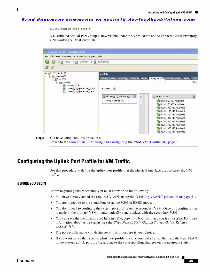
n1000v(config-port-prof)#
A Distributed Virtual Port Group is now visible under the VSM Name on the vSphere Client Inventory > Networking > DataCenter tab.
Step 2 You have completed this procedure. Return to the Flow Chart: Installing and Configuring the VSM VM (Continued), page 9.
Configuring the Uplink Port Profile for VM TrafficUse this procedure to define the uplink port profile that the physical interface uses to carry the VM traffic.
BEFORE YOU BEGIN
Before beginning this procedure, you must know or do the following:
• You have already added the required VLANs using the “Creating VLANs” procedure on page 31.
• You are logged in to the standalone or active VSM in EXEC mode.
• You don’t need to configure the system port profile on the secondary VSM. Once this configuration is made in the primary VSM, it automatically synchronizes with the secondary VSM.
• You can save the commands used here in a file, copy it to bootflash, and run it as a script. For more information about using scripts, see the Cisco Nexus 1000V Getting Started Guide, Release 4.0(4)SV1(1).
• The port profile name you designate in this procedure is your choice.
• If you want to use the system-uplink port profile to carry your data traffic, then add the data VLAN to the system-uplink port profile and make the corresponding changes on the upstream switch.
35Installing the Cisco Nexus 1000V Software, Release 4.0(4)SV1(1)
OL-19421-01
Send document comments to nexus1k -doc feedback@c i sco .com.
Installing and Configuring the VSM VM
• For more information about port profiles, see the Cisco Nexus 1000V Port Profile Configuration Guide, Release 4.0(4)SV1(1).
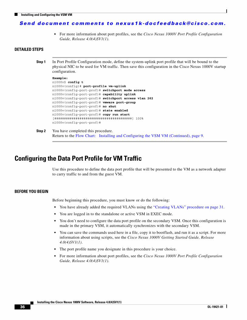
DETAILED STEPS
Step 1 In Port Profile Configuration mode, define the system-uplink port profile that will be bound to the physical NIC to be used for VM traffic. Then save this configuration in the Cisco Nexus 1000V startup configuration.
Example:n1000v$ config tn1000v(config)# port-profile vm-uplink n1000v(config-port-prof)# switchport mode accessn1000v(config-port-prof)# capability uplinkn1000v(config-port-prof)# switchport access vlan 262n1000v(config-port-prof)# vmware port-groupn1000v(config-port-prof)# no shutn1000v(config-port-prof)# state enabledn1000v(config-port-prof)# copy run start[########################################] 100%n1000v(config-port-prof)#
Step 2 You have completed this procedure. Return to the Flow Chart: Installing and Configuring the VSM VM (Continued), page 9.
Configuring the Data Port Profile for VM TrafficUse this procedure to define the data port profile that will be presented to the VM as a network adapter to carry traffic to and from the guest VM.
BEFORE YOU BEGIN
Before beginning this procedure, you must know or do the following:
• You have already added the required VLANs using the “Creating VLANs” procedure on page 31.
• You are logged in to the standalone or active VSM in EXEC mode.
• You don’t need to configure the data port profile on the secondary VSM. Once this configuration is made in the primary VSM, it automatically synchronizes with the secondary VSM.
• You can save the commands used here in a file, copy it to bootflash, and run it as a script. For more information about using scripts, see the Cisco Nexus 1000V Getting Started Guide, Release 4.0(4)SV1(1).
• The port profile name you designate in this procedure is your choice.
• For more information about port profiles, see the Cisco Nexus 1000V Port Profile Configuration Guide, Release 4.0(4)SV1(1).
36Installing the Cisco Nexus 1000V Software, Release 4.0(4)SV1(1)
OL-19421-01
Send document comments to nexus1k -doc feedback@c i sco .com.
Adding an ESX 4.0 Host to DVS
DETAILED STEPS
Step 1 Define the port profile to be used as the uplink port profile for VM NICs. Then save this configuration in the Cisco Nexus 1000Vstartup configuration.
Example:n1000v$ config tn1000v(config)# port-profile data262 n1000v(config-port-prof)# switchport mode accessn1000v(config-port-prof)# switchport access vlan 262n1000v(config-port-prof)# vmware port-group data262n1000v(config-port-prof)# no shutn1000v(config-port-prof)# state enabledn1000v(config-port-prof)# copy run start[########################################] 100%n1000v(config-port-prof)#
Step 2 You have completed this procedure. Return to the Flow Chart: Installing and Configuring the VSM VM (Continued), page 9.
Adding an ESX 4.0 Host to DVSUse this procedure to add the host to DVS.
Note If you are using VUM, then this procedure also installs the Cisco Nexus 1000V software onto the VEM automatically when the host is added to the switch.
BEFORE YOU BEGIN
Before beginning this procedure, you must know or do the following:
• The corresponding interface on the upstream switch must already be configured to allow the same VLANs as configured in the system-uplink port profile.
• In the example in this procedure, the traffic flow is set up as follows:
Note If you use the system-uplink profile to carry data traffic and the system-uplink profile has already been defined, then you do not need to assign the vm-uplink profile to another vmnic.
• If you are not using VUM, you have already installed the VEM software on the host using the Cisco Nexus 1000V Virtual Ethernet Module Software Installation Guide, Release 4.0(4)SV1(1).
Traffic VMNIC
Control VLAN system-uplink VMNIC
Packet VLAN system-uplink VMNIC
VM data VM-uplink Port Group
37Installing the Cisco Nexus 1000V Software, Release 4.0(4)SV1(1)
OL-19421-01
Send document comments to nexus1k -doc feedback@c i sco .com.
Adding an ESX 4.0 Host to DVS
• If you are using VUM, this procedure triggers VUM to install the Cisco Nexus 1000V VEM package.
• If you are using VUM, you have already loaded VUM and created a database for patches on the vCenter Server using the VMware instructions.
• The VMware Enterprise Plus license must already be installed on the host before the host can be added to the DVS. If not, then the host will not show up in the Add Host to Distributed Virtual Switch dialog box and you cannot add it.
• The VSM is already connected to the vCenter Server.
• To add multiple uplinks to the DVS and form a port channel with them, see the Cisco Nexus 1000V Interface Configuration Guide, Release 4.0(4)SV1(1).
DETAILED STEPS
Step 1 In the vSphere Client, click Inventory Networking.
You should see the following:
– A DVS with the switch name that you configured when Installing and Configuring the VSM VM, page 5.
– The port profiles that you created when Installing and Configuring the VSM VM, page 5.
Step 2 Do one of the following:
• If the DVS and the port profiles are present, continue with the next step.
• Otherwise, see the Cisco Nexus 1000V Troubleshooting Guide, Release 4.0(4)SV1(1).
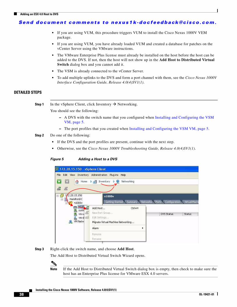
Figure 5 Adding a Host to a DVS
Step 3 Right-click the switch name, and choose Add Host.
The Add Host to Distributed Virtual Switch Wizard opens.
Note If the Add Host to Distributed Virtual Switch dialog box is empty, then check to make sure the host has an Enterprise Plus license for VMware ESX 4.0 servers.
38Installing the Cisco Nexus 1000V Software, Release 4.0(4)SV1(1)
OL-19421-01
Send document comments to nexus1k -doc feedback@c i sco .com.
Adding an ESX 4.0 Host to DVS
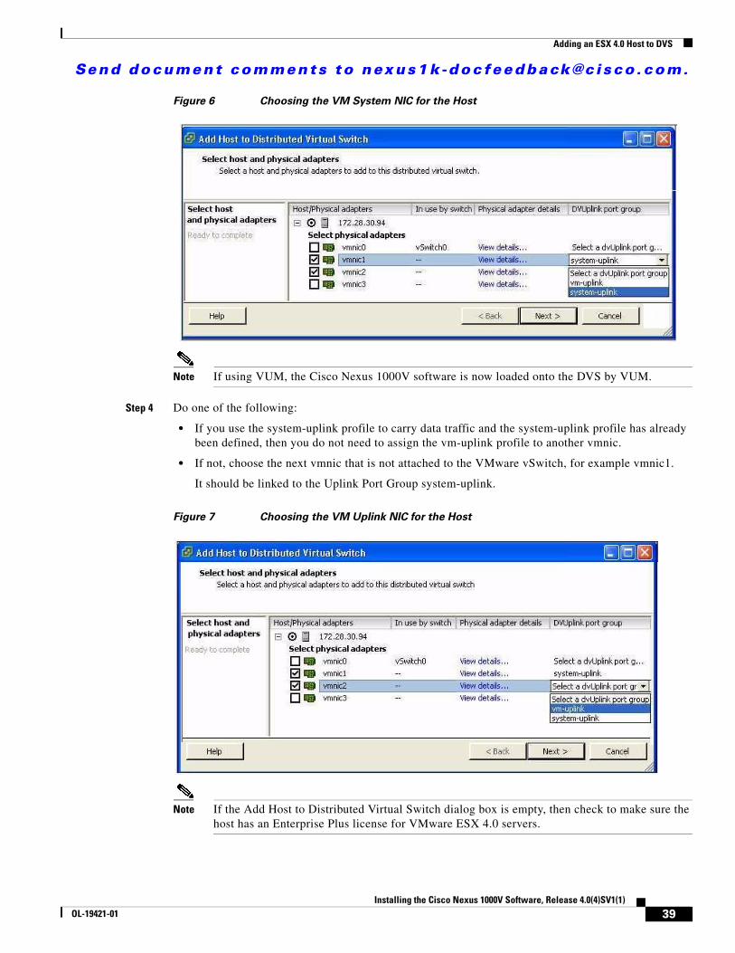
Figure 6 Choosing the VM System NIC for the Host
Note If using VUM, the Cisco Nexus 1000V software is now loaded onto the DVS by VUM.
Step 4 Do one of the following:
• If you use the system-uplink profile to carry data traffic and the system-uplink profile has already been defined, then you do not need to assign the vm-uplink profile to another vmnic.
• If not, choose the next vmnic that is not attached to the VMware vSwitch, for example vmnic1.
It should be linked to the Uplink Port Group system-uplink.
Figure 7 Choosing the VM Uplink NIC for the Host
Note If the Add Host to Distributed Virtual Switch dialog box is empty, then check to make sure the host has an Enterprise Plus license for VMware ESX 4.0 servers.
39Installing the Cisco Nexus 1000V Software, Release 4.0(4)SV1(1)
OL-19421-01
Send document comments to nexus1k -doc feedback@c i sco .com.
Verifying the Installation
Step 5 Choose the next vmnic that is not attached to the VMware vSwitch, for example vmnic2.
It should be linked to the Uplink Port Group vm-uplink.
Note To add multiple uplinks to the DVS and form a port channel with them, see the Cisco Nexus 1000V Port Profile Configuration Guide, Release 4.0(4)SV1(1).
Step 6 Click Next.
Step 7 Verify the port group assignment and click Finish.
Step 8 Do one of the following:
• If the host is successfully added to the DVS, continue with the next step.
• If the operation fails, see the Cisco Nexus 1000V Troubleshooting Guide, Release 4.0(4)SV1(1).
Step 9 You have completed this procedure. Return to the Flow Chart: Installing the Cisco Nexus 1000V Software, page 4.
Verifying the InstallationUse this procedure to verify that the software is installed as expected.
BEFORE YOU BEGIN
Before beginning this procedure, you must know or do the following:
• Once the host is added to DVS, the Server-Name is displayed in the show module command output. This should happen within 5 minutes of the module coming up on VSM. The server name is the equivalent of the host object name seen in vCenter Server and is fetched from the vCenter Server-VSM connection.
DETAILED STEPS
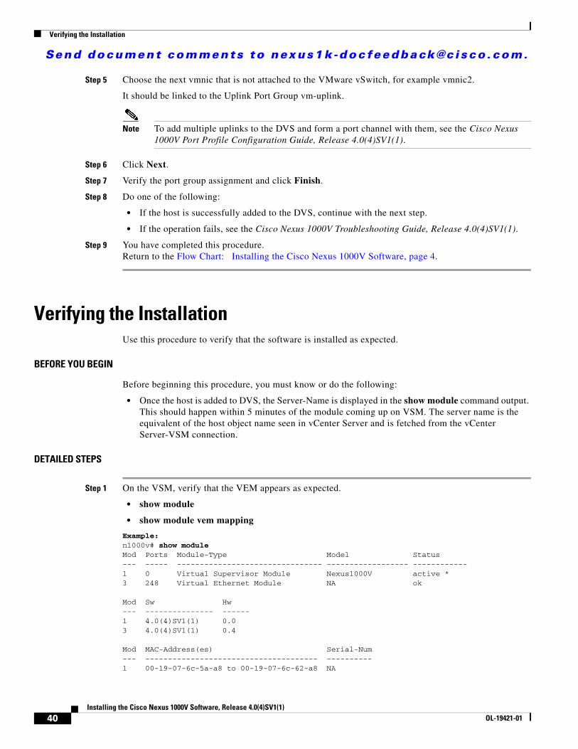
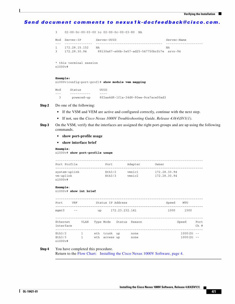
Step 1 On the VSM, verify that the VEM appears as expected.
• show module
• show module vem mapping
Example:n1000v# show moduleMod Ports Module-Type Model Status--- ----- -------------------------------- ------------------ ------------1 0 Virtual Supervisor Module Nexus1000V active *3 248 Virtual Ethernet Module NA ok
Mod Sw Hw--- --------------- ------1 4.0(4)SV1(1) 0.03 4.0(4)SV1(1) 0.4
Mod MAC-Address(es) Serial-Num--- -------------------------------------- ----------1 00-19-07-6c-5a-a8 to 00-19-07-6c-62-a8 NA
40Installing the Cisco Nexus 1000V Software, Release 4.0(4)SV1(1)
OL-19421-01
Send document comments to nexus1k -doc feedback@c i sco .com.
Verifying the Installation
3 02-00-0c-00-03-00 to 02-00-0c-00-03-80 NA
Mod Server-IP Server-UUID Server-Name--- --------------- ------------------------------------ --------------------1 172.28.15.152 NA NA3 172.28.30.94 89130a67-e66b-3e57-ad25-547750bcfc7e srvr-94
* this terminal sessionn1000v#
Example:n1000v(config-port-prof)# show module vem mapping
Mod Status UUID--- ----------- ---- 3 powered-up 8f2aa4d8-1f1a-34d8-90ee-9ca7ace00ad3
Step 2 Do one of the following:
• If the VSM and VEM are active and configured correctly, continue with the next step.
• If not, see the Cisco Nexus 1000V Troubleshooting Guide, Release 4.0(4)SV1(1).
Step 3 On the VSM, verify that the interfaces are assigned the right port-groups and are up using the following commands.
• show port-profile usage
• show interface brief
Example: n1000v# show port-profile usage
--------------------------------------------------------------------------------Port Profile Port Adapter Owner--------------------------------------------------------------------------------system-uplink Eth3/2 vmnic1 172.28.30.94vm-uplink Eth3/3 vmnic2 172.28.30.94n1000v#
Example: n1000v# show int brief
--------------------------------------------------------------------------------Port VRF Status IP Address Speed MTU--------------------------------------------------------------------------------mgmt0 -- up 172.23.232.141 1000 1500
--------------------------------------------------------------------------------Ethernet VLAN Type Mode Status Reason Speed PortInterface Ch #--------------------------------------------------------------------------------Eth3/2 1 eth trunk up none 1000(D) --Eth3/3 1 eth access up none 1000(D) --n1000v#
Step 4 You have completed this procedure. Return to the Flow Chart: Installing the Cisco Nexus 1000V Software, page 4.
41Installing the Cisco Nexus 1000V Software, Release 4.0(4)SV1(1)
OL-19421-01
Send document comments to nexus1k -doc feedback@c i sco .com.
Starting the VMs
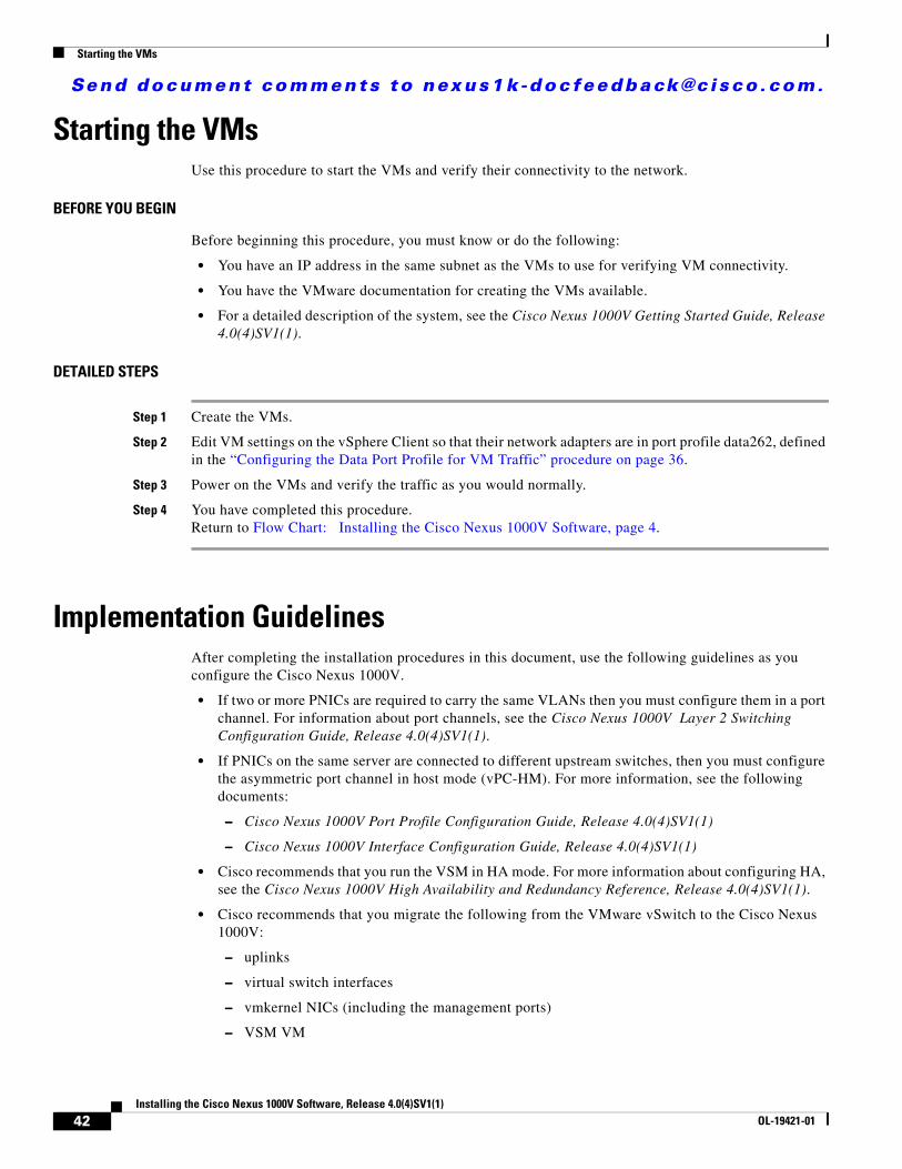
Starting the VMsUse this procedure to start the VMs and verify their connectivity to the network.
BEFORE YOU BEGIN
Before beginning this procedure, you must know or do the following:
• You have an IP address in the same subnet as the VMs to use for verifying VM connectivity.
• You have the VMware documentation for creating the VMs available.
• For a detailed description of the system, see the Cisco Nexus 1000V Getting Started Guide, Release 4.0(4)SV1(1).
DETAILED STEPS
Step 1 Create the VMs.
Step 2 Edit VM settings on the vSphere Client so that their network adapters are in port profile data262, defined in the “Configuring the Data Port Profile for VM Traffic” procedure on page 36.
Step 3 Power on the VMs and verify the traffic as you would normally.
Step 4 You have completed this procedure. Return to Flow Chart: Installing the Cisco Nexus 1000V Software, page 4.
Implementation GuidelinesAfter completing the installation procedures in this document, use the following guidelines as you configure the Cisco Nexus 1000V.
• If two or more PNICs are required to carry the same VLANs then you must configure them in a port channel. For information about port channels, see the Cisco Nexus 1000V Layer 2 Switching Configuration Guide, Release 4.0(4)SV1(1).
• If PNICs on the same server are connected to different upstream switches, then you must configure the asymmetric port channel in host mode (vPC-HM). For more information, see the following documents:
– Cisco Nexus 1000V Port Profile Configuration Guide, Release 4.0(4)SV1(1)
– Cisco Nexus 1000V Interface Configuration Guide, Release 4.0(4)SV1(1)
• Cisco recommends that you run the VSM in HA mode. For more information about configuring HA, see the Cisco Nexus 1000V High Availability and Redundancy Reference, Release 4.0(4)SV1(1).
• Cisco recommends that you migrate the following from the VMware vSwitch to the Cisco Nexus 1000V:
– uplinks
– virtual switch interfaces
– vmkernel NICs (including the management ports)
– VSM VM
42Installing the Cisco Nexus 1000V Software, Release 4.0(4)SV1(1)
OL-19421-01
Send document comments to nexus1k -doc feedback@c i sco .com.
Implementation Guidelines
Related DocumentationCisco Nexus 1000V includes the following documents available on Cisco.com:
General Information
Cisco Nexus 1000V Release Notes, Release 4.0(4)SV1(1)
Cisco Nexus 1000V and VMware Compatibility Information, Release 4.0(4)SV1(1)
Install and Upgrade
Cisco Nexus 1000V Software Installation Guide, Release 4.0(4)SV1(1)
Cisco Nexus 1000V Virtual Ethernet Module Software Installation Guide, Release 4.0(4)SV1(1)
Configuration Guides
Cisco Nexus 1000V License Configuration Guide, Release 4.0(4)SV1(1)
Cisco Nexus 1000V Getting Started Guide, Release 4.0(4)SV1(1)
Cisco Nexus 1000V Interface Configuration Guide, Release 4.0(4)SV1(1)
Cisco Nexus 1000V Layer 2 Switching Configuration Guide, Release 4.0(4)SV1(1)
Cisco Nexus 1000V Port Profile Configuration Guide, Release 4.0(4)SV1(1)
Cisco Nexus 1000V Quality of Service Configuration Guide, Release 4.0(4)SV1(1)
Cisco Nexus 1000V Security Configuration Guide, Release 4.0(4)SV1(1)
Cisco Nexus 1000V System Management Configuration Guide, Release 4.0(4)SV1(1)
Cisco Nexus 1000V High Availability and Redundancy Reference, Release 4.0(4)SV1(1)
Reference Guides
Cisco Nexus 1000V Command Reference, Release 4.0(4)SV1(1)
Cisco Nexus 1000V MIB Quick Reference
Troubleshooting and Alerts
Cisco Nexus 1000V Troubleshooting Guide, Release 4.0(4)SV1(1)
Cisco Nexus 1000V Password Recovery Guide
Cisco NX-OS System Messages Reference
This document is to be used in conjunction with the documents listed in the “Related Documentation” section.
Cisco and the Cisco logo are trademarks or registered trademarks of Cisco and/or its affiliates in the U.S. and other countries. To view a list of Cisco trademarks, go to this URL: www.cisco.com/go/trademarks. Third-party trademarks mentioned are the property of their respective owners. The use of the word partner does not imply a partnership relationship between Cisco and any other company. (1110R)
43Installing the Cisco Nexus 1000V Software, Release 4.0(4)SV1(1)
OL-19421-01
Send document comments to nexus1k -doc feedback@c i sco .com.
Implementation Guidelines
Any Internet Protocol (IP) addresses used in this document are not intended to be actual addresses. Any examples, command display output, and figures included in the document are shown for illustrative purposes only. Any use of actual IP addresses in illustrative content is unintentional and coincidental.
© 2009 Cisco Systems, Inc. All rights reserved.
44Installing the Cisco Nexus 1000V Software, Release 4.0(4)SV1(1)
OL-19421-01