installing and configuring mivoice mx-one
TRANSCRIPT

INSTALLATION INSTRUCTIONS
INSTALLATION INSTRUCTIONS
Installing and Configuring MiVoice MX-ONE
Peter Petterssonppettersson(T. Silvennoinen)tsilvennoinen

4/1531-ANF 901 43 Uen T1 2018-08-31 2
NOTICE
The information contained in this document is believed to be accurate in all respects but is not warranted by Mitel Networks™ Corporation (MITEL®). Mitel makes no warranty of any kind with regards to this material, including, but not limited to, the implied warranties of merchantability and fitness for a particular purpose. The information is subject to change without notice and should not be construed in any way as a commitment by Mitel or any of its affiliates or subsidiaries. Mitel and its affiliates and subsidiaries assume no responsibility for any errors or omissions in this document. Revisions of this document or new editions of it may be issued to incorporate such changes.
No part of this document can be reproduced or transmitted in any form or by any means - electronic or mechanical - for any purpose without written permission from Mitel Networks Corporation.
TRADEMARKS
The trademarks, service marks, logos and graphics (collectively "Trademarks") appearing on Mitel's Internet sites or in its publications are registered and unregistered trademarks of Mitel Networks Corporation (MNC) or its subsidiaries (collectively "Mitel") or others. Use of the Trademarks is prohibited without the express consent from Mitel. Please contact our legal department at [email protected] for additional information. For a list of the worldwide Mitel Networks Corporation registered trademarks, please refer to the website: http://www.mitel.com/trademarks.
© Copyright 2018, Mitel Networks Corporation
All rights reserved
INSTALLING AND CONFIGURING MIVOICE MX-ONE
3 4/1531-ANF 901 43 Uen T1 2018-08-31
1 INTRODUCTION
This document describes the SW installation and initial configuration of the MX-ONE.
The installation can be of the following three types:
Turnkey solutionThe customer has bought both server and SW from Mitel. Mitel provides the operating system (SLES 12 SP3 x86_64) and containing the MX-ONE Software included on Recovery Image.
SW OnlyThe customer provides its own SLES 12 SP3 x86_64 compatible Server and Operating System, OS (SLES 12 SP3 x86_64) including Linux support subscrip-tion. Mitel provides a Media Kit containing the MX-ONE Software. OS needs to be installed on the server(s). For details see 4.2 SW Only Installation on page 12. The hardware clock of the server must also be set to a rather accurate value.
Virtual ApplianceA virtual appliance is a virtual machine image designed to run on a virtualization platform. The MX-ONE Service Node Virtual appliance includes the Operating System (SLES 12 SP3 x86_64) and the MX-ONE Software.
A template file with all settings needed for a new virtual machine is included on the Recovery Image, use the media to install the operating system and applica-tion.
The MX-ONE Service Node Virtual Appliance runs on top of a VMware infra-structure, vSphere ESXi 5.5 hypervisor (minimum).
This means that of the ASUs, only ASU-II supports virtualization, and ASU-II only supports vSphere ESXi 5.5 (up to U3), i.e. no later versions.
Please note that Mitel does not supply any VMware software together with the MX-ONE Service Node.
1.1 SCOPE
The installation and initial configuration of the MX-ONE takes place upon first startup of the system.
The first part of the document specifies the preparation steps for the Installing OS and configuring the application.
The media gateways are initiated after the initial system configuration.
Note: For Linux related configuration questions, see the SuSE Linux Enterprise Server 12 documentation, https://www.suse.com/documentation.
1.2 TARGET GROUP
The target group for this document is personnel installing and configuring software for the MX-ONE.

4/1531-ANF 901 43 Uen T1 2018-08-31 4
INTRODUCTION
1.3 PREREQUISITES
1.3.1 GENERAL
Before proceeding with the software installation:
• Make sure all cables are firmly connected and all hardware is properly installed. See the installation instructions for INSTALLING MX-ONE HARDWARE.
• The layout of the network must be defined. See the description for MX-ONE SYSTEM PLANNING.
• It is recommended for engineers installing the MX-ONE to be acquainted with the following areas:
– MX-ONE Service Node– MX-ONE Lite (3U, with MGU board)– MX-ONE 1U (former Slim, with MGU board)– MX-ONE Classic (7U, with MGU board)– MX-ONE Media Server (SW variant for SIP-only scenarios). See descrip-
tion of the MX-ONE Media Server for installation instructions for the MX-ONE Media Server.
– Certification – TCP/IP Networks – XML – Linux – Databases, like Cassandra, LDAP, SQL, AD
• The following equipment is necessary:
– VGA screen – Keyboard – DVD Reader – USB memory – Mouse (if needed) – USB hub (in case a USB mouse is used)
• Special consideration must be taken for the system database (Cassandra) deployment and server requirements. For systems larger than 6 Service Node servers/LIMs, it is recommended to deploy the system database on a stand-alone server (i.e. not co-located with the SN). See the description SYSTEM DATABASE (CASSANDRA).
• Special consideration must be taken for redundancy. See chapter 7 Redundancy Considerations on page 30.
1.3.2 SW ONLY INSTALLATION
Note: The customer provides its own SLES 12 SP3 compatible server and Operating System (including Linux support subscription).
These are the minimum requirements for the MX-ONE Service Node when performing a SW Only installation. For a server with up to 1000 extensions (users):
• Processor: 2 GHz Intel Celeron J1900 2.0 GHz Quad core (ASU Lite)• RAM memory: 8 GB• Disc: 120 GB• Intel x86 architecture • Chipset with watchdog implementation• LAN ports: 2 (100 or 1000 Mb/s)

INSTALLING AND CONFIGURING MIVOICE MX-ONE
5 4/1531-ANF 901 43 Uen T1 2018-08-31
• USB: 2 (USB 2.0 at least)• Console I/O
For a server with up to 7500 extensions (users) the following minimum requirements apply.
• Processor: Intel i7 2.4 GHz Quad Core (or equivalent) (ASU-II)• RAM memory: 16 GB• Disc: 250 GB• Intel x86 architecture• Chipset with watchdog implementation• LAN ports: 2 (100 or 1000 Mb/s)• USB: 2 (USB 2.0 at least)• Console I/O
The following CDs or DVDs must be available:
• SuSE Linux Enterprise Server 12 SP3, bootable media• MX-ONE Media Kit
For larger installations (up to 15000 extensions) industry standard Intel X86 server, such as DELL Poweredge R3x0 series with a Xeon E3-12XX V5 3.0 Ghz Quad Core or later CPU, with 32GB memory minimum should be used.
1.3.3 VIRTUAL APPLIANCE
For more information, see description MX-ONE SERVICE NODE VIRTUALIZATION and installation instruction MX-ONE SERVICE NODE VIRTUAL APPLIANCE.

4/1531-ANF 901 43 Uen T1 2018-08-31 6
OVERVIEW
2 OVERVIEW
2.1 GENERAL
The MX-ONE can comprise one or several MX-ONE Service Nodes, each, depending on the type of media gateway, can serve from one to fifteen media gateways. For more information, see the installation instructions for INSTALLING MX-ONE HARDWARE.
Each MX-ONE Service Node is assigned a Server number. Server 1 will distribute the configuration data to all other Servers. Also, Server 1 hosts the MX-ONE Service Node Manager, which provides a web interface to set the telephony related data for the system, like number series, operators, and so on, after the initial configuration.MX-ONE Provisioning Manager can be installed on any server part of the system or on a stand-alone. It is used for configuring user settings.
Network redundancy can be achieved by connecting the servers to a redundant network infrastructure and using Ethernet bonding.
Server redundancy is achieved by arranging the servers in clusters. A cluster is a number of servers with one designated standby server. The MX-ONE can have a maximum of 10 servers defined per cluster.
For more information about redundancy, see the description for MIVOICE MX-ONE.
Basic network configuration data setup for every Server needs to be done locally.
The media gateways are added to the system after the system configuration, in the post-installation routines.
Note: In a system with more than 32 Servers (LIMs), it is recommended to configure a Standard Server, with large hard disk capacity as Server 1, or else it will not be possible to upgrade the system.
Note: Do not use YAST, since it may cause system malfunctions. (Instead use the mxone_maintenance tool).
2.2 WORKFLOW
Depending on the type of installation, use of HTTPS, TLS and so on, the procedure for installation and initial configuration differ.
1. Obtain digital certificate (only if HTTPS or TLS is used)
2. Collect needed IP addresses for the system
3. Install operating system and application
4. Perform Network setup for Server 1 (LIM 1)
5. Perform network setup for all other servers
6. Configure the entire system and perform the installation.
7. Reconfigure MX-ONE Service Node Manager if HTTPS is used as mxon-e_admin using MX-ONE maintenance tool.
8. Initial configuration completed.
INSTALLING AND CONFIGURING MIVOICE MX-ONE
7 4/1531-ANF 901 43 Uen T1 2018-08-31
3 PREPARATIONS
Installation and network configuration is done at once, starting with the server that should be Server 1. Configure the network on Server 1, continue with the rest of the server in the system.
Note: Before the installation can begin, the network configuration must be known.
Note: New installation of server 1 will change the system Hardware ID. It is strongly recommended that a permanent license file is ordered after Installation Test for MX-ONE is completed.
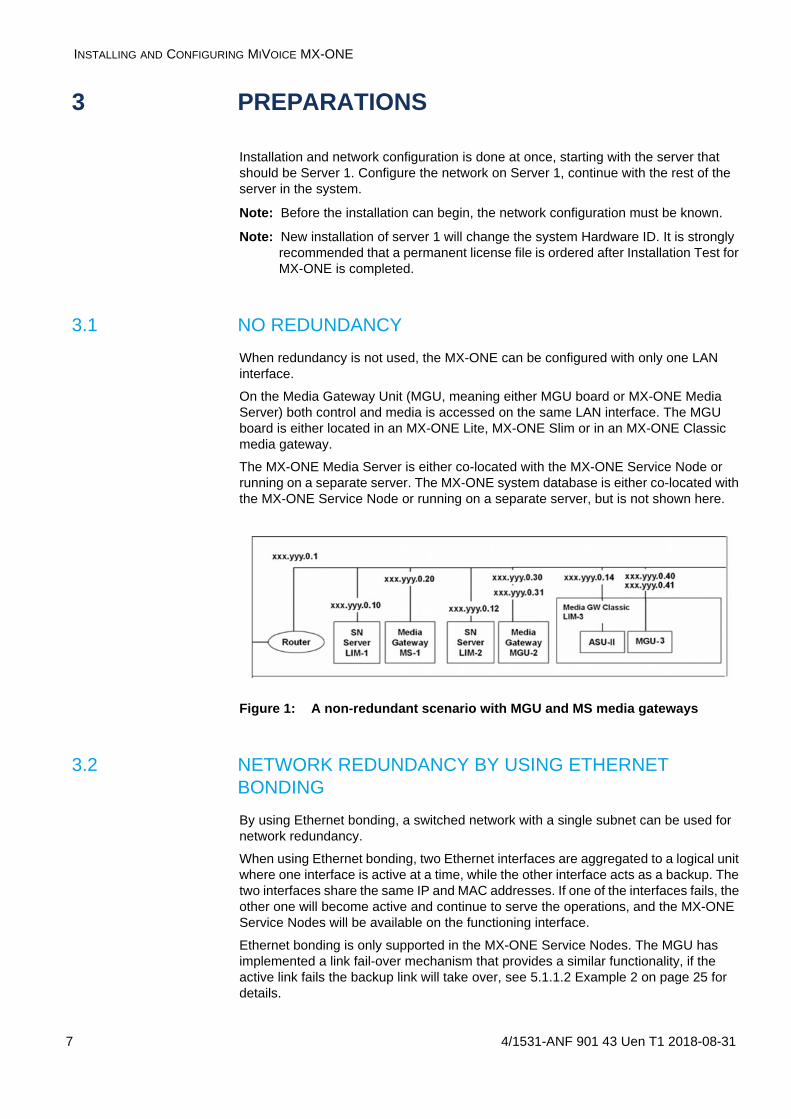
3.1 NO REDUNDANCY
When redundancy is not used, the MX-ONE can be configured with only one LAN interface.
On the Media Gateway Unit (MGU, meaning either MGU board or MX-ONE Media Server) both control and media is accessed on the same LAN interface. The MGU board is either located in an MX-ONE Lite, MX-ONE Slim or in an MX-ONE Classic media gateway.
The MX-ONE Media Server is either co-located with the MX-ONE Service Node or running on a separate server. The MX-ONE system database is either co-located with the MX-ONE Service Node or running on a separate server, but is not shown here.
Figure 1: A non-redundant scenario with MGU and MS media gateways
3.2 NETWORK REDUNDANCY BY USING ETHERNET BONDING
By using Ethernet bonding, a switched network with a single subnet can be used for network redundancy.
When using Ethernet bonding, two Ethernet interfaces are aggregated to a logical unit where one interface is active at a time, while the other interface acts as a backup. The two interfaces share the same IP and MAC addresses. If one of the interfaces fails, the other one will become active and continue to serve the operations, and the MX-ONE Service Nodes will be available on the functioning interface.
Ethernet bonding is only supported in the MX-ONE Service Nodes. The MGU has implemented a link fail-over mechanism that provides a similar functionality, if the active link fails the backup link will take over, see 5.1.1.2 Example 2 on page 25 for details.

4/1531-ANF 901 43 Uen T1 2018-08-31 8
PREPARATIONS
The allowed configurations for network redundancy using Ethernet bonding are shown in Figure 2.
Figure 2: Server redundancy with Ethernet bonded network redundancy. System database is not shown here.
The MGU set up as for a non-redundant system. see chapter 5.1.1.1 Example 1 on page 25.
3.3 OBTAINING A DIGITAL CERTIFICATE FOR THE MX-ONE SERVICE NODE MANAGER
The MX-ONE supports HTTPS for secure access to the web-based MX-ONE Service Node Manager. During the installation, the system is configured to use either standard HTTP or HTTPS. With HTTPS, it is necessary to configure a private key, and a digital certificate, to be used in the system.
For more information about the MX-ONE Provisioning Manager and MX-ONE Service Node Manager certificate handling, see the description for AD AUTHENTICATION.
The digital certificate can either be generated as a self-signed certificate during the installation or bought from a commercial certificate supplier. Note that a self-signed certificate provides limited security unless the certificate is properly and securely distributed to all clients. It is recommended to use a self-signed certificate during the installation, a commercial certificate can be installed later if needed. For more information about obtaining a digital certificate, see the operational directions for CERTIFICATE MANAGEMENT.
INSTALLING AND CONFIGURING MIVOICE MX-ONE
9 4/1531-ANF 901 43 Uen T1 2018-08-31
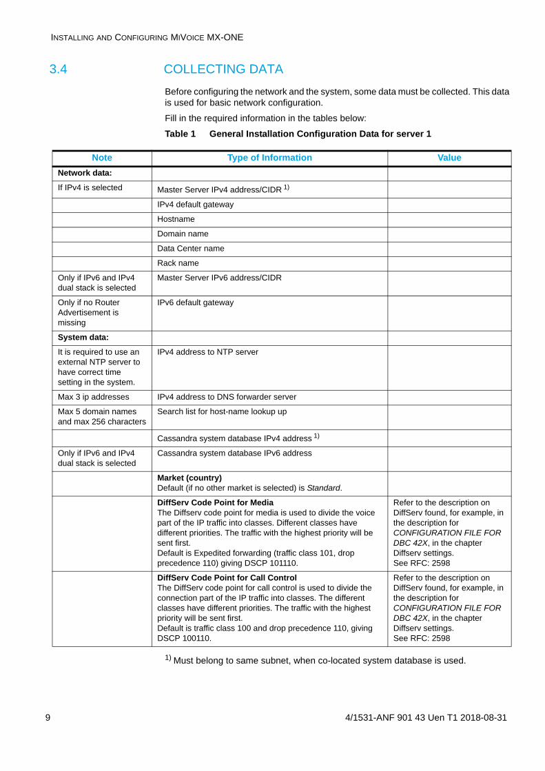
3.4 COLLECTING DATA
Before configuring the network and the system, some data must be collected. This data is used for basic network configuration.
Fill in the required information in the tables below:
Table 1 General Installation Configuration Data for server 1
1) Must belong to same subnet, when co-located system database is used.
Note Type of Information Value
Network data:
If IPv4 is selected Master Server IPv4 address/CIDR 1)
IPv4 default gateway
Hostname
Domain name
Data Center name
Rack name
Only if IPv6 and IPv4 dual stack is selected
Master Server IPv6 address/CIDR
Only if no Router Advertisement is missing
IPv6 default gateway
System data:
It is required to use an external NTP server to have correct time setting in the system.
IPv4 address to NTP server
Max 3 ip addresses IPv4 address to DNS forwarder server
Max 5 domain names and max 256 characters
Search list for host-name lookup up
Cassandra system database IPv4 address 1)
Only if IPv6 and IPv4 dual stack is selected
Cassandra system database IPv6 address
Market (country)Default (if no other market is selected) is Standard.
DiffServ Code Point for MediaThe Diffserv code point for media is used to divide the voice part of the IP traffic into classes. Different classes have different priorities. The traffic with the highest priority will be sent first.Default is Expedited forwarding (traffic class 101, drop precedence 110) giving DSCP 101110.
Refer to the description on DiffServ found, for example, in the description for CONFIGURATION FILE FOR DBC 42X, in the chapter Diffserv settings.See RFC: 2598
DiffServ Code Point for Call ControlThe DiffServ code point for call control is used to divide the connection part of the IP traffic into classes. The different classes have different priorities. The traffic with the highest priority will be sent first.Default is traffic class 100 and drop precedence 110, giving DSCP 100110.
Refer to the description on DiffServ found, for example, in the description for CONFIGURATION FILE FOR DBC 42X, in the chapter Diffserv settings.See RFC: 2598

4/1531-ANF 901 43 Uen T1 2018-08-31 10
PREPARATIONS
Note: It is recommended to print a separate copy of Table 2 Data for basic network configuration and Server (LIM) configuration on page 10 for each Server in the system and fill in the values for easy access to the information during the configuration. Data for the media gateways is needed after the system configuration.
Table 2 Data for basic network configuration and Server (LIM) configuration
Clustering is used for server redundancy. Here each MX-ONE Service Node that belongs to the cluster is assigned an alias IP address to each of its connected LANs. For more information, see the description for MIVOICE MX-ONE, on Redundancy.
Note: Table 3 and Table 4 refer to the Cluster related data.
Table 3 Cluster Configuration Data
Table 4 Configuration Data for each Server in the Cluster
Note Type of Information Value
Server (LIM) number
Server host nameA unique host name.
ARP parameters (Applicable only for bonded systems)
ARP interval (in milliseconds)
ARP validate Normally set to 1.
ARP IP Target Normally set to the default gateway address, and the media gateway address.
Primary Normally eth0.
Server network interface - 1 (eth0)
IP address
Subnet mask
Default gateway
Type of Information Value
Cluster name
Server NumberThe Servers that should be included in the cluster
Standby Server Host Name
Sync TimeThe time in hours and minutes when the standby server will synchronize the reload data.
Type of Information Value
Base Address, old and new, Network Interface - 1
IPv4 Addresses
Base Address, old and new, Network Interface - 1 (if dual stack selected)
IPv6 Addresses

INSTALLING AND CONFIGURING MIVOICE MX-ONE
11 4/1531-ANF 901 43 Uen T1 2018-08-31
3.5 TURNKEY INSTALLATION PREPARATIONS
For more information, see operational directions Administrator User's Guide, chapter 5.1 Using recovery image.
3.6 SW ONLY PREPARATIONS
During the OS installation the appropriate Media kit (which contains a number of xml files for the installation and MX-ONE Installation package) must be available in a USB memory stick. The files contain the correct settings for the installation.
Note: The MX-ONE will use the whole disk, and will re-format the entire disk. No other software can reside in any partition.
3.7 VIRTUAL APPLIANCE
For more information, see description MX-ONE Service Node Virtualization and installation instruction, MX-ONE Service Node Virtual Appliance.
4/1531-ANF 901 43 Uen T1 2018-08-31 12
INSTALLATION AND INITIAL CONFIGURATION
4 INSTALLATION AND INITIAL CONFIGURA-TION
Depending if the installation is a Turnkey or SW Only installation the starting point differs.
• If it is a Turnkey installation the basic network configuration can be performed directly, see chapter 4.1 Recovery image installation on page 12.
• If the installation is a SW Only installation the Operating System and the MX-ONE Service Node need to be installed on the server prior the basic network configuration, see chapter 4.2 SW Only Installation on page 12.
4.1 RECOVERY IMAGE INSTALLATION
To install the recovery image, perform the following steps:
OS Install
1. Boot the machine from the storage media with Recovery Image.
2. Enter BIOS mode.
3. Change the date if necessary. Other parameters might also need to be modified (Set Time Zone).
4. If USB is used, make sure that the boot order is: Hard disk, USB.
5. Re-boot the machine from the storage media.
6. At the initial screen select the “Install” option. Press Enter.
Note: If the partitioning fails, the disk is not clean. Use the FDISK utility to partition the disk. For example, run fdisk from a Linux Live-CD.
Note: Beware of the timeout when the first screen appears. In case no selection is made, the system will boot with default parameters and the configuration file will not be read.
7. Log on as root. (Default password is set to "changeme". Change it during the installation.)
8. Restart the server by typing reboot at the shell prompt.
9. The OS is now installed on the server HW.
10. Repeat for all servers as necessary.
MX-ONE Service Node Install
To start the installation of MX-ONE, login as root and start the installation with command /sbin/net_setup. See chapter 4.4 Network and System Configuration on page 13 for details. This will setup the network and start the installation. Always start from Server1.
4.2 SW ONLY INSTALLATION
Note: The customer provides its own SLES compatible server and Operating System, OS (SLES 12 SP3 x86_64) including Linux support subscription. Mitel provides a Media Kit containing the MX-ONE Software.
INSTALLING AND CONFIGURING MIVOICE MX-ONE
13 4/1531-ANF 901 43 Uen T1 2018-08-31
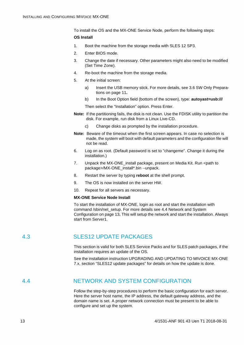
To install the OS and the MX-ONE Service Node, perform the following steps:
OS Install
1. Boot the machine from the storage media with SLES 12 SP3.
2. Enter BIOS mode.
3. Change the date if necessary. Other parameters might also need to be modified (Set Time Zone).
4. Re-boot the machine from the storage media.
5. At the initial screen:
a) Insert the USB memory stick. For more details, see 3.6 SW Only Prepara-tions on page 11.
b) In the Boot Option field (bottom of the screen), type: autoyast=usb:///
Then select the “Installation” option. Press Enter.
Note: If the partitioning fails, the disk is not clean. Use the FDISK utility to partition the disk. For example, run disk from a Linux Live-CD.
c) Change disks as prompted by the installation procedure.
Note: Beware of the timeout when the first screen appears. In case no selection is made, the system will boot with default parameters and the configuration file will not be read.
6. Log on as root. (Default password is set to "changeme". Change it during the installation.)
7. Unpack the MX-ONE_install package, present on Media Kit. Run <path to package>/MX-ONE_install*.bin --unpack.
8. Restart the server by typing reboot at the shell prompt.
9. The OS is now installed on the server HW.
10. Repeat for all servers as necessary.
MX-ONE Service Node Install
To start the installation of MX-ONE, login as root and start the installation with command /sbin/net_setup. For more details see 4.4 Network and System Configuration on page 13. This will setup the network and start the installation. Always start from Server1.
4.3 SLES12 UPDATE PACKAGES
This section is valid for both SLES Service Packs and for SLES patch packages, if the installation requires an update of the OS.
See the installation instruction UPGRADING AND UPDATING TO MIVOICE MX-ONE 7.x, section “SLES12 update packages” for details on how the update is done.
4.4 NETWORK AND SYSTEM CONFIGURATION
Follow the step-by-step procedures to perform the basic configuration for each server. Here the server host name, the IP address, the default gateway address, and the domain name is set. A proper network connection must be present to be able to configure and set up the system.
4/1531-ANF 901 43 Uen T1 2018-08-31 14
INSTALLATION AND INITIAL CONFIGURATION
For a system with server redundancy, the standby server is treated as an ordinary server.
Perform the server installation and configuration in the following order:
• Initial setup of master server
• Initial setup of other servers
• Configuring the entire system (from master server)
• Post-installation Configuration
4.4.1 INITIAL SETUP OF THE MASTER SERVER
Note: This section provides a high-level description of the installation steps. Not all options are described. For example, while IPv4 configuration steps are given, the IPv6 steps are not. For IPv6 configurations, follow the options that appear on the GUI when you choose IPv6. Similarly for other options such as QoS settings or network bonding, follow the options that appear in the GUI.
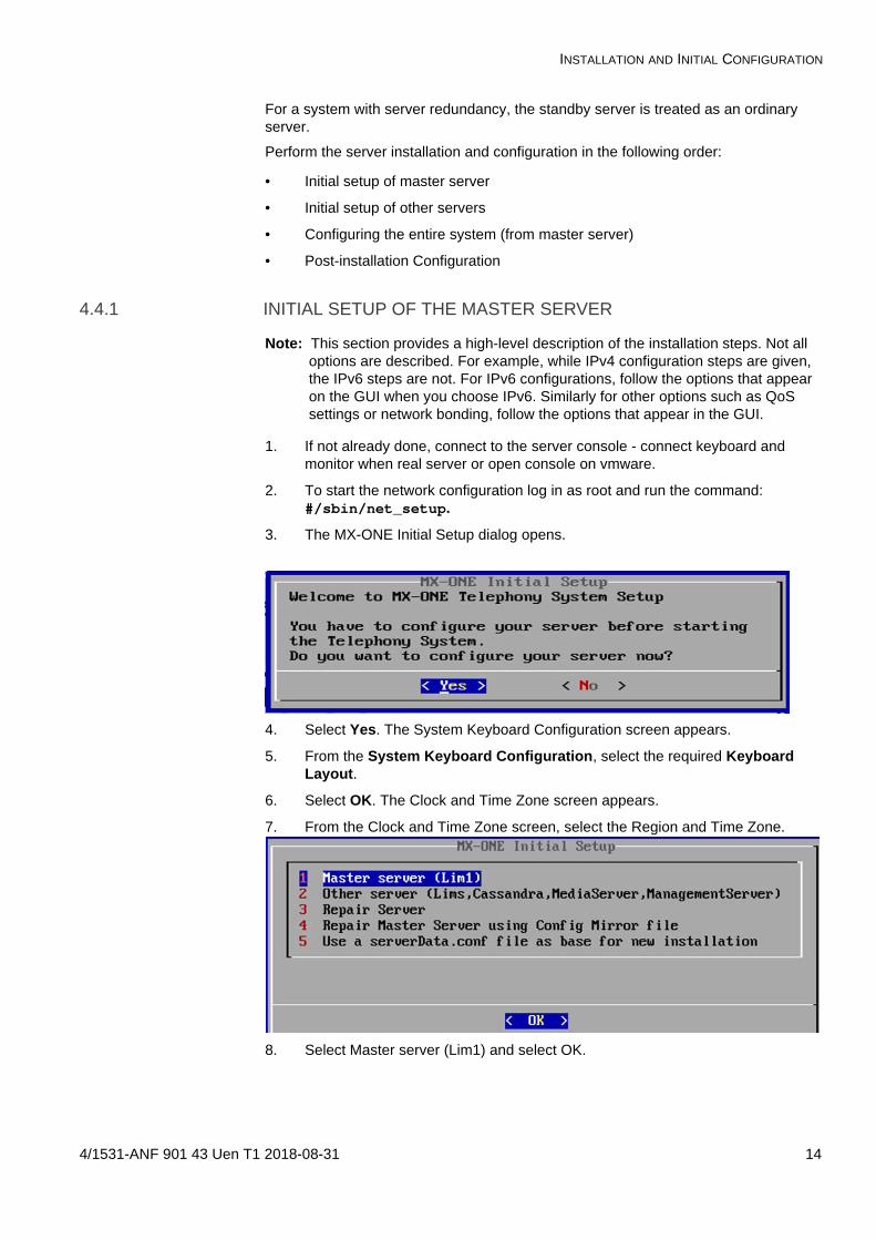
1. If not already done, connect to the server console - connect keyboard and monitor when real server or open console on vmware.
2. To start the network configuration log in as root and run the command: #/sbin/net_setup.
3. The MX-ONE Initial Setup dialog opens.
4. Select Yes. The System Keyboard Configuration screen appears.
5. From the System Keyboard Configuration, select the required Keyboard Layout.
6. Select OK. The Clock and Time Zone screen appears.
7. From the Clock and Time Zone screen, select the Region and Time Zone.
8. Select Master server (Lim1) and select OK.

INSTALLING AND CONFIGURING MIVOICE MX-ONE
15 4/1531-ANF 901 43 Uen T1 2018-08-31
9. You can choose if bonding shall be used or not. Note that bonding may be also configured after the initial setup is done using mxone_maintenance tool.
10. Select the type of IP stack to be used - either only IPv4 or both IPv4 and IPv6 (dual stack). (In this example, only an IPv4 address is configured.) Select Configure only ipv4 and click OK.
11. Enter the configuration details such as the IPv4 address, hostname, domain name, data center name, rack name of master server, and then click OK.
12. Enter the passwords for user accounts root, mxone_admin, and mxone_user. The minimum password length is 8 characters. The basic data to continue the initial setup is now collected and the installation may start. It can be continued in the console or later after logging in through SSH.
13. Select Yes to stop the installation and continue later or select No to proceed. Regardless of the selection, confirm the data provided.
If you select No the configuration data entered will be erased and the initial setup wizard will be restarted.

4/1531-ANF 901 43 Uen T1 2018-08-31 16
INSTALLATION AND INITIAL CONFIGURATION
14. After confirming, select Yes to apply the configuration. If action is completed successfully a confirmation is presented:
Note: No refers that the server is restarted and all data is erased.
15. The initial setup for this server is now completed as master server.
16. Keep this interface to master server open and perform the initial setup of the other servers that shall be part of that system, see section INITIAL SETUP OF OTHER SERVERS. If no other servers shall be installed or when for all other servers the initial setup was completed, in the master server console press c to continue with the installation. Continue with section CONFIGURING THE ENTIRE SYSTEM (FROM THE MASTER SERVER).
4.4.2 INITIAL SETUP OF OTHER SERVERS
Note: The following procedure must be run on all servers in the system, both LIMs (that are not Lim1), and other servers such as standalone Media Servers, Cassandra server, or Provisioning Manager applications.
Note: The intended Cassandra servers (nodes), or at least ONE Cassandra server (node), MUST be initiated before you configure the entire system, i.e. finish the initiation of the Master LIM. In other words, a functioning system REQUIRES a system database.
1. If not already done, connect to the server console - connect keyboard and monitor when real server or open console on vmware.
2. To start the network configuration log in as root (password "changeme") on server1/lim1 (master server) and run the following command: #sbin/net_setup.

INSTALLING AND CONFIGURING MIVOICE MX-ONE
17 4/1531-ANF 901 43 Uen T1 2018-08-31
3. The MX-ONE Initial Setup dialog opens.
4. Select Yes. The System Keyboard Configuration screen opens.
5. Select the Keyboard Layout.
6. Select OK. The Clock and Time Zone screen appears.
7. From the Clock and Time Zone screen, select the Region and Time Zone.
8. Select OK and select the type of initial setup.
9. Select Other server (Lims, Cassandra, MediaServer, ManagementServer).
10. Repeat Step 10 to Step 16 of the master server initial setup. Make sure you provide the IP address of the master server when specifying configuration details for IPv4 or IPv6.
11. After the configuration has been applied, continue the configuration in master server.
12. Continue with the System configuration in the master server console. See, CONFIGURING THE ENTIRE SYSTEM (FROM THE MASTER SERVER).
4.4.3 CONFIGURING THE ENTIRE SYSTEM (FROM THE MASTER SERVER
After you install LIM1 and other servers, you must go back to server1 and configure the system by using the following procedure:

4/1531-ANF 901 43 Uen T1 2018-08-31 18
INSTALLATION AND INITIAL CONFIGURATION
1. When the Initial setup is completed for all servers those will appear in the master servers console:
2. If all servers are present press c in the master server to finalize the initial setup.
3. Select the trial license type (Traditional or Feature based).
4. In the example here Traditional is selected and click OK.
5. Next must be the IP address of the NTP server configured. Note, if the NTP server is not reachable or does not reply correctly the finalization of the initial setup will stop and you have to restart it.
6. Enter the IP address to forward DNS (1-3), which is optional. You can leave it empty or enter up to three different addresses comma separated. Continue.

INSTALLING AND CONFIGURING MIVOICE MX-ONE
19 4/1531-ANF 901 43 Uen T1 2018-08-31
7. Select the market to use in the system.
8. Next the Quality of Service settings may be modified.
9. Next select on which server a LIM will be running.
10. Change the LIM number if needed (only for non server 1).

4/1531-ANF 901 43 Uen T1 2018-08-31 20
INSTALLATION AND INITIAL CONFIGURATION
11. Select on which server System Database (Cassandra) shall be installed. At least one server must be selected.
12. Configure an alias IP addresses for all the selected Cassandra servers.
Note: Make sure that the IPs are not in use in the network.
13. Select if Media Server should run on any server.

INSTALLING AND CONFIGURING MIVOICE MX-ONE
21 4/1531-ANF 901 43 Uen T1 2018-08-31
14. A summary of the collected data will be presented.
15. After confirming the data the installation starts and completes.
Note: You must log off from the root after step 15, and login to mxone-admin again before you start the post-installation configuration.
4.4.4 POST-INSTALLATION CONFIGURATION
After the successful servers installation, follow the steps in this section to conclude the configuration.
1. Configure the media gateways. See Chapter 5.1 Configure the Media Gateways on page 24.
2. Some optional features are not loaded by default. See Chapter 4.5 Optional Programs on page 22.
To use one of those features, load the corresponding program unit(s) use the command pu_add -unit -fill, see the command description for ADD/REMOVE/CHANGE PROGRAM.
3. Enter the command board_config -scan from the MX-ONE Service Node mdsh shell, see the command description for BOARD CONFIGURATION. This is to

4/1531-ANF 901 43 Uen T1 2018-08-31 22
INSTALLATION AND INITIAL CONFIGURATION
make sure that all virtual boards on the Media Gateway are registered by the MX-ONE Service Node.
4. Enter the command alarm from the MX-ONE Service Node mdsh shell, see the command description for ALARM FUNCTIONS. This is to make sure there are no serious alarms in the alarm log.
5. If applicable, check status of SW RAID 1. Logon as root and key command mdadm -D /dev/md0, mdadm -D /dev/md1 and cat /proc/mdstat.
6. Optional, network redundancy, i.e. Bonding
Run the command mxone_maintenance that starts the Maintenance Utility and choose Option Bonding settings in system.
7. Optional, server redundancy.
For details see Operational directions SERVER REDUNDANCY.
8. Execute Installation Test for MX-ONE.
For details see Operational Directions for 9 Installation Test for MIVoice MX-ONE on page 37.
9. Place a new order on the order desk to receive a permanent license file.
For more details, see Operation Directions for ADMINISTRATOR USER'S GUIDE.
4.5 OPTIONAL PROGRAMS
For efficiency reasons there are a number of program units that are not loaded by default.Optional features
Feature Program Units
Paging PGP1, PGP3
ISDN S0 ITBP, ITLBP, ITLP, ITP
SNMP w/Ericsson MIB ASNMP
TL1 TLP1
TL4 TLP4
TL11 TLP11
TL12 TLP12
TL19 TLP19
TL22 TLP22
TL25 TLP25
TL26 TLP26
TL35 TLP35
TL37 TLP37
TL38 TLP38
TL45 TLP45
TL49 TLP49
TL50 TLP50
TL51 TLP51

INSTALLING AND CONFIGURING MIVOICE MX-ONE
23 4/1531-ANF 901 43 Uen T1 2018-08-31
For more information, see the parameter description for the UNIT parameter, in Technical Reference Guide, MML parameters.
4.6 OTHER OPTIONAL SOFTWARE
If certain optional external applications are wanted, there may be additional SW (not part of the Service Node) that also needs to be installed. Examples are the CSTA phase III WebService/SOAP protocol, management applications like the Provisioning Manager and the IP Phone SW Server (IPP), and CIL/SMDR post-processing applications. See installation documentation for each function.
4.7 RECOVERING FROM FAILURE
If the installation is not successful, it is recommended to run the installation again from the beginning from the Recovery Image.
TL72 TLP72
TL81 TLP81
TL95 TLP95
Feature Program Units

4/1531-ANF 901 43 Uen T1 2018-08-31 24
COMPLETING THE CONFIGURATION
5 COMPLETING THE CONFIGURATION
Most of the remaining configuration of the MX-ONE Service Node can be made using the web based MX-ONE Service Node Manager. The MX-ONE Service Node Manager provides different walk-throughs for the setup of the MX-ONE. See the MX-ONE SERVICE NODE MANAGER USER GUIDE for further information.
Users of the MX-ONE Service Node Manager can be configured either by MX-ONE Provisioning Manager or through the Linux system. For more information, see the description MX-ONE PROVISIONING MANAGER and the installation instruction INSTALLING MX-ONE PROVISIONING MANAGER.
It is also possible to configure the system using the command line interface, see the description for COMMAND ADMINISTRATION.
5.1 CONFIGURE THE MEDIA GATEWAYS
For the MX-ONE Service Node to be able to communicate with its media gateway it must know the IP address of the media gateway control port, eth0. If needed, it must be set on the media gateway hardware.
There are two major types of MX-ONE media gateways:
• The media gateway built around the MGU board.
For instructions on how to set the IP address, to be able to reach the MGU hard-ware over the network, see chapter 8 MGU board setup on page 34.
• The MX-ONE Media Server, is a pure software implementation which emulates the MGU board (except for the TDM interfaces). This media gateway can only be used for SIP-only scenarios.
For instructions on how to configure the MX-ONE Media Server, see the descrip-tion of MX-ONE Media Server.
5.1.1 CONFIGURE MGU INTERFACES BY COMMAND
The interfaces of the MGU (both MGU board and MX-ONE Media Server) can also configured by MDSH commands set directly (used in the examples below). To configure the control interface use the command media_gateway_config. To configure the media interface use the command media_gateway_interface.

INSTALLING AND CONFIGURING MIVOICE MX-ONE
25 4/1531-ANF 901 43 Uen T1 2018-08-31
5.1.1.1 Example 1
Configure an MGU-based media gateway for Server 2 as media gateway B. Redundancy is not used. Connect LAN0 interface of the MGU to the network (MGUs internal switch interfaces eth0 is used for control and eth2 is used for media ).
example# media_gateway_config -i -m 2B --mgw-type mgu --cidr 192.168.5.30/25 --default-gateway 192.168.5.1 --symbolic-name Stockholm
example#media_gateway_interface -i -m 2B --cidr 192.168.5.31/25 --default-gateway 192.168.5.1
5.1.1.2 Example 2
Configure a MGU-based media gateway for Server 2 as media gateway B. Link failover redundancy is used. Interface LAN0 and LAN1 should be connected to the same switched network, but to different physical switched to achieve redundancy (MGUs internal switch interfaces eth0 is used for control and eth2 is used for media).
Link failover functionality will be activated when both LAN0 and LAN1 interfaces are connected to active network switch port.
example# media_gateway_config -i -m 2B --mgw-type mgu --cidr 192.168.5.30/25 --default-gateway 192.168.5.1 --symbolic-name Stockholm
example#media_gateway_interface -i -m 2B --cidr 192.168.5.31/25 --default-gateway 192.168.5.1
5.2 CONFIGURATION CHANGES IN OTHER SYSTEMS IN THE PRIVATE NETWORK (OPTIONAL)
In certain installation cases, where the new system shall partly or fully replace an old system, i.e. when only part of the extensions are moved, or when several old systems are ‘merged’, or an old system is split in several new systems, or the move has to be

4/1531-ANF 901 43 Uen T1 2018-08-31 26
COMPLETING THE CONFIGURATION
done in stages, it can be relevant to do some temporary configuration changes in the old system(s) in the same private network.
The extension data will eventually be removed from the old system (or the entire old system removed), but the extension directory numbers and the extensions may temporarily be kept assigned but vacant, in order to for example re-direct calls to the new location. To do this, configuration is required in the old system(s) using the number analysis and Private Network Routing O&M functions. The extension data can also temporarily remain in the old system(s), but will then be seen as existing in other commands (like extension print commands). The procedure could be for example like this:
1. Install the new system and the extensions to be moved. Initiate the wanted tie-lines between old and new system.
2. In the old system, convert the number type of the vacant extension number to external destination:
number_vacant_conversion_initiate -number 1000..1020/ -numbertype ex -newnumbertype -ed
3. Initiate a PNR destination to route the calls to the extension’s new location. In this example the former extension number 1000 (which is now an external destina-tion) will be addressing the number 057311000, which should lead to the exten-sion 1000 in the new system:
LCDDI:TAB=PNR,ENTRY=1000&&1020,FRCT=1; (to set which entries to allow in PNR). Repeat for all relevant extension numbers, if they are not in series.
LCDDI:TAB=RCT,FRCT=1,PRE=05731; (to reach an external line via PNR).
4. The extension in the new system will now be ‘active’, while the extension number in the old system will be ‘passive’, and calls addressing that old number will be re-directed to the new system. At some time, when the move is finished, the old system should either be removed, or the extension and number data be erased.
See operational directions SMOOTH MIGRATION for more details and context.

INSTALLING AND CONFIGURING MIVOICE MX-ONE
27 4/1531-ANF 901 43 Uen T1 2018-08-31
6 MAINTENANCE
To change the configuration after the installation, as root run the command mxone_maintenance that starts the Maintenance Utility.
Note: Not all the parameters can be modified after the installation. To update the configuration, select one of the following options from the online menu:
Package handlingSelect this option to list, add, distribute or remove installation packages.
Upgrade MiVoice MX-ONE VersionSelect this option to list, prepare or upgrade the system to newer version.
Rollback MiVoice MX-ONE VersionSelect this option to list or rollback the system to previous versions.
Repair LIM or SSH keys in systemSelect this option to repair a failing LIM or ssh keys or generate network config-uration for faulty server.
Uninstall complete system, all MiVoice MX-ONE versionsSelect this option to uninstall complete MiVoice MX-ONE system.
Server in systemSelect this option to list, add and remove server.
LIM in systemSelect this option to list, add and remove LIM.
Standby server in systemSelect this option to list, convert free server to standby server or convert standby server to free server.
License handlingSelect this option to show hardware ID, list license usage and install new license file.
Market settingsSelect this option to list or change market setting in the system.
Diff serv parametersSelect this option to list or change QoS setting in the system.
Note: To change Diffserv value in MGU or Media Server, refer to media_gateway_info command.
Bonding settings in systemSelect this option to list, add or remove bonding.
Cluster handlingSelect this option to handle clusters in system.
Note: When changing a cluster, e.g. changing fallback type, adding a Server (LIM) to cluster, the cluster functionality is stopped during the reconfiguration.
DNS forward settingsSelect this option to list and change DNS forward settings and search domains.
Seccheck settingsSelect this option to enable/disable security check settings.
User management in serverSelect this option to list, add, remove and change user accounts in the system. Select this option to enable/disable V.24 access to Service Node daemon.

4/1531-ANF 901 43 Uen T1 2018-08-31 28
MAINTENANCE
Web server configSelect this option to configure Web server. e.g. for MX-ONE Service Node Manager.
Manage add-on softwareSelect this option to list, install, upgrade and uninstall add-on software.
Manage SLES software repositoriesSelect this option to list, add and remove SLES Service Packs or Patch Pack-ages.
Manage Certificates and TLS settings in the systemSelect this option to configure certificates and TLS settings.
Manage settings for Media ServerSelect this option to list, add and remove Media Servers.
6.1 RENEWING CERTIFICATES
A self-signed certificate is usually valid for 360 days. If the system is configured to use HTTPS with a self-signed certificate, the MX-ONE Service Node Manager web server will not work properly when the certificate has expired. To solve this, renew the self-signed certificate.
To renew a commercial certificate, follow the supplier instructions.
For more information about renewing certificates, see the operational directions for CERTIFICATE MANAGEMENT.
6.2 CHANGING MX-ONE SERVICE NODE IP ADDRESS AND NETWORK NAME
Changing the MX-ONE Service Node IP address and network names are advanced operations that must only be performed by an experienced technician who has deep knowledge of Linux, the MX-ONE Service Node, and the Media Gateway. For more information about changing the MX-ONE Service Node IP address and network names, contact your local support.
6.3 CHANGING AUTHENTICATION LOGIN FROM LINUX TO MX-ONE PROVISIONING MANAGER
When MX-ONE Provisioning Manager is installed on the same server as MX-ONE Service Node Manager, authentication method is not automatically set to MX-ONE Provisioning Manager authentication.
The authentication method for logging on to MX-ONE Service Node Manager is changed for existing MX-ONE Service Node installations.
a) Login as mxone_admin
b) Run command: sudo mxone_maintenance
c) Select Web server config option.
Authentication method is configured on the server where MX-ONE Service Node Manager (MX-ONE Service Node Manager or eri_om) is installed. Ensure that the proper protocol (HTTP or HTTPS) is chosen for the MX-ONE Provisioning Manager

INSTALLING AND CONFIGURING MIVOICE MX-ONE
29 4/1531-ANF 901 43 Uen T1 2018-08-31
server. Port is automatically configured accordingly. It is important to acknowledge the re-start of mxone_jboss service after the configuration process, otherwise, the changes do not have any effect.
6.4 INCREASING HEAP MEMORY SIZE IN JBOSS CONFIGU-RATION FILE
Follow the steps below for increasing the heap memory size in Jboss configuration:
1. Login to Provisioning Manager/ SNM server with root user credentials.
2. Go to path: cd /opt/jboss/bin/
3. Edit standalone.conf file and change the options Xms512m and Xmx512m to the desired values. In the example below, options are changed to 2048m.
JAVA_OPTS="-Xms2048m -Xmx2048m -XX:MaxPermSize=300m -Dsun.rmi.dgc.client.gcInterval=3600000 -Dsun.rmi.dgc.server.gcIn-terval=3600000 -Djava.library.path=/opt/eri_sn/lib:/opt/jboss/bin -Dfile.encoding=UTF-8 -XX:+UseConcMarkSweepGC -XX:+CMSPerm-GenSweepingEnabled -XX:+CMSClassUnloadingEnabled"
4. Save the changes.
5. Run command: webserver_config.
6. Select Re-start webserver option.
4/1531-ANF 901 43 Uen T1 2018-08-31 30
REDUNDANCY CONSIDERATIONS
7 REDUNDANCY CONSIDERATIONS
7.1 PREREQUISITES
• The standby Server (LIM) must have enough performance to be able to take over from an arbitrary Server in the cluster.
• The standby Server must have enough hard disk memory to be able to store two data backups of each Server included in the cluster. A data backup normally requires around 100 MB of disk space.
• Within a cluster there must be enough bandwidth to efficiently transmit data backups to the standby server.
Note: For reference, see the Redundancy section of the description for MX-ONE SYSTEM PLANNING.
7.2 GENERAL
The MX-ONE Servers can be connected to a redundant network, using Ethernet bonding.
Certain features, like for example, operator queue and ACD backup group, can be duplicated and placed in different Servers. This increases the reliability for specific features.
Server redundancy means that a standby MX-ONE Server takes over the failing Server's identity, including the IP address (the alias address), and will continue to act as Service Node (LIM). The media gateways of the failing server will be controlled by the standby server.
At server redundancy the servers are assigned both real and alias IP addresses. When a Server goes down, the alias addresses of the failing Server are moved to the standby server. The Service Node is reloaded and started on the standby server using the Server number of the failing Server.
The standby server will take over any failing servers identity and continue execution of call processing. It is recommended that the standby server is of the same type as the failing server.
To achieve server redundancy the Servers are arranged in clusters. A cluster is a number of Servers with one designated standby Server. The MX-ONE can have a maximum of 10 Servers per cluster.
The HLR backup/redundancy feature provides a possibility for H.323 and SIP extensions to temporarily register, on certain conditions, to a backup HLR in another server (LIM) than the ordinary HLR server (LIM).
You can use several Cassandra database centers but you must have to connect 1 Cassandra database node per Data Center, which could be a co-located one with a Service Node or standalone.
7.3 LIMITATIONS
This section lists the known limitations with the redundancy solution in MX-ONE that must be considered when deploying both network and server redundancy.

INSTALLING AND CONFIGURING MIVOICE MX-ONE
31 4/1531-ANF 901 43 Uen T1 2018-08-31
7.3.1 NETWORK REDUNDANCY
• When the MX-ONE Media Server is used, the redundancy functions of the server on which the MX-ONE Media Server is running will be valid.
• With Ethernet bonded network redundancy, it is recommended to define at least two ARP IP targets per server. If only one ARP IP target is specified and that target is unreachable communication will change back and forth between the interfaces. If this happens it will most likely lead to lost IP packets and fatal distur-bances in the server communication.
7.3.2 SERVER REDUNDANCY
• For performance reasons, a backup cluster cannot include MX-ONE Service Nodes (LIMs) in different geographical areas.
• If a Server does not belong to any backup cluster, for example, a remote Server, it will not have any server redundancy.
• If several ordinary servers in the same cluster fail, the MX-ONE Service Node with the highest priority will execute on the standby server. If one Server is running on the standby server when another MX-ONE Service Node with higher priority fails, the MX-ONE Service Node with highest priority will finally execute on the standby server. The other failed MX-ONE Service Nodes will not operate.
• If automatic fallback is configured for the cluster, the fallback will take place when the server is functioning again. This can create problems if the regular server goes up and down repeatedly during a short period of time.
7.3.3 HLR BACKUP/REDUNDANCY
• HLR backup is supported for H.323 and SIP extensions, but requires support for load distribution (for H.323) or DNS SRV (for SIP) in the terminals.
• While registered to a backup HLR, several services cannot be utilized by the user. For example group functions, queue function, monitoring, and charging functions.
• IP end points that do not support periodic re-registration and load distribution mechanisms cannot have the HLR backup feature.
7.4 CONFIGURATION
7.4.1 SERVER REDUNDANCY
When server redundancy is used alias addresses are set for the ordinary MX-ONE Service Nodes in the cluster.

4/1531-ANF 901 43 Uen T1 2018-08-31 32
REDUNDANCY CONSIDERATIONS
The alias addresses should belong to the same subnets as the ordinary IP addresses. Address symmetry is recommended to facilitate maintenance.
Figure 3: Server redundancy without network redundancy
Server redundancy can also be used in a Ethernet bonded network, see figure below. For more information, see MX-ONE System Planning.
Figure 4: Server redundancy with Ethernet bonded network redundancy
The following entities should be setup to the alias server addresses:
• IP extensions (H.323 and SIP)
• Media Gateway (for the NFS server)
• CSTA
• Operator Work Station (NOW)
7.4.2 HLR BACKUP/REDUNDANCY
When HLR backup shall be used, activate the service by the ASPAC command with parameter 198 (PARNUM = 198).
Configure the IP terminals and the DNS server appropriately, to support load balancing.
7.4.3 OTHER SERVICES
7.4.3.1 DNS
The internal DNS of the MX-ONE Service Nodes are configured automatically at installation. Here the base addresses are used. This internal DNS must not be modified.

INSTALLING AND CONFIGURING MIVOICE MX-ONE
33 4/1531-ANF 901 43 Uen T1 2018-08-31
If the user wants DNS entries for phone server records the address to the customer local DNS should be specified.
7.4.3.2 GICI
GICI is not affected by redundancy, as the MX-ONE Service Node is connected as a client to the GICI server. The GICI server should be located on the same side of the router as the IP phones.
7.4.3.3 NTP
The clock time on any of the Servers (LIMs) should not be changed manually, because the NTP server (specified in the configuration file) will synchronize the clocks of all the Servers.
Note: Manual change of time or date on any MX-ONE Service Node should not be done.
7.4.3.4 Certain legacy features with common functions
There are a few usually optional legacy features that have common function programs, which in 2-server systems are only loaded in one server (the non-I/O server) as default. Those features are:
• TDM-DECT (CF program unit CTLM)
• Paging (DPM)
• CCSS7 trunks (MTM)
• Route optimization/Path Replacement for ISDN/DPNSS (ROM)
• Traffic Recording (TMM1, TMM2) and
• SOM (ZODBM, ZOHC, ZOMM)
In such systems, you can improve redundancy for those features by manually loading the mentioned specific program units, and also in the second server. In systems with 3 or more servers, these common functions get loaded in 2 or more servers.

4/1531-ANF 901 43 Uen T1 2018-08-31 34
MGU BOARD SETUP
8 MGU BOARD SETUP
8.1 GENERAL
In order to access the MGU board over the network the IP address of its control port on LAN 0 must be set.
Figure 5: MGU board LAN ports
The following Ethernet ports are available, see Table 5 MGU ports on page 34.
Table 5 MGU ports
8.2 PREREQUISITES FOR MGU BOARDS
• Root authority is needed to access the MGU console.
• Make a terminal connection to the USB port in the front of the MGU.
Use cable TSR 899 135/1, which is a USB to D-Sub cable, plus a 9 pin D-Sub female to female adaptor.
Use a terminal program, for example, kermit.
• Baud rate is set to 9600 bits/sec, 8 data bits, no parity, 1 stop bit.
LAN 0 LAN 1 (redundancy)
Control eth0 eth1
Media eth2 eth3

INSTALLING AND CONFIGURING MIVOICE MX-ONE
35 4/1531-ANF 901 43 Uen T1 2018-08-31
No HW or SW flow control.
If run with kermit on a MX-ONE Service Node a control file, kermitrc, is needed under /root with the following content:
– set line /dev/ttyS0
– set speed 9600
– set transmit prompt 46
– set take echo on
– set carrier-watch off
– set flow none
– connect
• The default address for eth0 is: 192.168.1.2/24
8.3 SET ETH0 AND DEFAULT GW ADDRESSES
1. Login with user: admin, password: admin.
Change password for admin. (You will get a warning, and be prompted to change the password).
Switch to root, by: su -
The default password is root.
Change password for root. (You will get a warning, and be prompted to change the password).
2. Follow the on-screen instructions.
Note: Use the command mgu-setup --help for guidance.
The process is completed in the MX-ONE Service Node Manager where, for example, redundancy is set. There it is also mandatory to set the media ports.
This is followed by a reboot.
Note: The mgu-setup script only allows IPv4 addresses to be set. In case using IPv6 control, the command nvparams must be used to set the IPv6 control address (eth0_ip6) and default IPv6 route (def_route6).
8.4 BOOT PARAMETERS
When the MX-ONE Service Node has sent the board parameters and the reboot is done, the set parameters can be checked. Use the command:
nvparams -dispar all
The following parameters can, for example, be displayed:
Table 6 Boot parameters
Parameter name Default or (Example)
*ROF_num ROF 137 6304/x
*ROF_rev Rxx
*ROF_ser T01xxxxxxx

4/1531-ANF 901 43 Uen T1 2018-08-31 36
MGU BOARD SETUP
*eth0_mac (00:13:5E:F0:AD:C4)
*eth1_mac (00:13:5E:F0:AD:C5)
*eth2_mac (00:13:5E:F0:AD:F6)
*eth3_mac (00:13:5E:F0:AD:F7)
eth0_ip 192.168.1.2/24
eth1_ip 192.168.2.2/24
eth2_ip 192.168.1.3/24
eth3_ip 192.168.2.3/24
nfsroot /mgu_root
lilo_arg root=/dev/mtdblock1 rw rootfstype=yaffs2 noatime
autoupdate no
nfs_server 192.168.1.10
def_route 192.168.1.1
def_route1 192.168.2.1
autostart (yes)
phy0_mode (AUTO)
phy1_mode (AUTO)
lan_active (BOTH)
lan_primary (LAN0)
Parameter name Default or (Example)

INSTALLING AND CONFIGURING MIVOICE MX-ONE
37 4/1531-ANF 901 43 Uen T1 2018-08-31
9 INSTALLATION TEST FOR MIVOICE MX-ONE
This section describes installation test at the end of the installation procedure.
To check functionality for the MX-ONE proceed as follows:
1. Make a call from an IP telephone to another IP telephone.
2. Make a call from an IP telephone to an analog telephone.
3. Make a call from an IP telephone to an external number.
4. Make a call from an external number to an IP telephone.
5. Make a call from a digital telephone to another digital telephone.