installation - voice communications inc. triad/starplus triad 1-… · ksu ac power plug .....3-26...
TRANSCRIPT

Feature Package 3
TRIAD 1/2/3Installation
a new dimension in business communications

STARPLUSTM Triad 1/2/3TM
Installation Manual
Part Number: 8050-12 Issue 3.2 - March 2001

Copyright © 2001 VODAVI Technology, Inc.
All Rights Reserved
This material is copyrighted by VODAVI Technology, Inc., and may be duplicated byAuthorized Dealers only. Any unauthorized reproductions, use or disclosure of thismaterial, or any part thereof, is strictly prohibited and is a violation of the CopyrightLaws of the United States (17 U.S.C. Section 101 et. seq.).
VODAVI reserves the right to make changes in specifications at any time and withoutnotice. The information furnished by VODAVI in this material is believed to be accurateand reliable, but is not warranted to be true in all cases.
STARPLUS and TRIAD™ are Registered trademarks of VODAVI Technology, Inc.
mlj/2001
Issue Release Date Changes
2 8-99 Feature Package 2 {FP2} enhancements have been added.Manual content contains extensive revisions.
2.1 12-99 Manual content has been revised.
3 5-00 Manual content has been reformatted.
3.1 8-00 Manual content has been revised to clarify Feature Package 3.
3.2 3-01 Manual content has been revised for correctness and clarity.
LIFE SUPPORT APPLIC ATIONS POLICY
VODAVI Communications Systems products are not authorized for and should notbe used within Life Support applications. Life Support systems are equipmentintended to support or sustain life and whose failure to perform when properly usedin accordance with instructions provided can be reasonably expected to result insignificant personal injury or death.
VODAVI Communications Systems warranty is limited to replacement of defectivecomponents and does not cover injury to persons or property or otherconsequential damages.

Contents
1 IntroductionRegulatory Information (U.S.A.) ...................................................................... 1-3
Telephone Company Notification .......................................................... 1-3Incidence of Harm ........................................................................................ 1-4Changes in Service ....................................................................................... 1-4Maintenance Limitations ........................................................................... 1-4Hearing Aid Compatibility ........................................................................ 1-4UL/CSA Safety Compliance ....................................................................... 1-4Notice of Compliance ................................................................................. 1-5
Toll Fraud Disclaimer .......................................................................................... 1-5
2 Triad 1/2 System InstallationIntroduction ........................................................................................................... 2-3Site Preparation .................................................................................................... 2-4
General Site Considerations ..................................................................... 2-4Back-Board Installation .............................................................................. 2-5Verify On-Site Equipment .......................................................................... 2-5
KSU & Power Supply (PSU) Installation ........................................................ 2-8Mounting the Triad 1 Basic KSU .............................................................. 2-8
KSU and Power Supply (PS) Installation ...................................................... 2-11Mounting the Triad 2 Basic KSU .............................................................. 2-11Mounting the Expansion KSU (EKSU) .................................................... 2-14
Ring Generator Installation (RGU) ................................................................. 2-16Power Supply Unit Installation ....................................................................... 2-18KSU Grounding ..................................................................................................... 2-20Power Line Surge Protection ........................................................................... 2-21
Lightning Protection ................................................................................... 2-21KSU AC Power Plug ...................................................................................... 2-21
PCB Installation ..................................................................................................... 2-22PCB Handling & General Installation ..................................................... 2-22
Main Processor Board (MPB) Installation .................................................... 2-24Phase Lock Loop Unit (PLLU) ................................................................... 2-26Modem Unit (MODU) .................................................................................. 2-27
Miscellaneous Interface Unit (MISU) Installation ..................................... 2-29

ii March 2001
Installing the Serial Interface Unit (SIU) ................................................ 2-31CO/PBX Connections .......................................................................................... 2-33
Loop Start CO Interface Board (LCOB) .................................................. 2-33DID Interface Board (DIDB) ....................................................................... 2-36T-1 Interface Board (T1IB) .......................................................................... 2-39Primary Rate Interface Board (PRIB) ....................................................... 2-48Basic Rate Interface Board (BRIB) ............................................................ 2-49ISDN and T1 Clocking ................................................................................. 2-52
Station Connections ........................................................................................... 2-57Electronic Telephone Interface Board (ETIB) ...................................... 2-57Single Line Interface Board (SLIB) ........................................................... 2-60Digital Telephone Interface Board (DTIB) ............................................ 2-64
System Wiring ....................................................................................................... 2-67Battery Back-Up Wiring Installation ....................................................... 2-67MPB and SIU RS232C Port Wiring ........................................................... 2-68MISU Wiring .................................................................................................... 2-69Station Wiring ................................................................................................ 2-69
Wall Mounting the Electronic Telephone ................................................... 2-73Wall Mounting the Digital Telephone .......................................................... 2-74Headset Installation ............................................................................................ 2-75Caller ID Interface Unit Installation ............................................................... 2-75
Selecting the Cable ...................................................................................... 2-75Programming the KSU ................................................................................ 2-77
3 Triad 3 System InstallationIntroduction ........................................................................................................... 3-3Site Preparation .................................................................................................... 3-3
General Site Considerations ..................................................................... 3-3Back-Board Installation .............................................................................. 3-4Verify On-Site Equipment .......................................................................... 3-5
KSU & Power Supply (PSU) Installation ........................................................ 3-7Mounting the Basic KSU ............................................................................. 3-7Mounting the Expansion Cabinet (EKSU1) .......................................... 3-8Mounting the Expansion Cabinet (EKSU2) .......................................... 3-9
Ring Generator Installation (RGU) ................................................................. 3-11KSU Grounding ..................................................................................................... 3-12

March 2001 iii
Power Supply Unit Installation ....................................................................... 3-14AC/DC (PS-10A or PS-15A) ........................................................................ 3-14DC/DC (with BCU & 48VU) ......................................................................... 3-16Battery Back-up Wiring Installation ....................................................... 3-24Power Line Surge Protection ................................................................... 3-26Lightning Protection ................................................................................... 3-26KSU AC Power Plug ...................................................................................... 3-26
PCB Installation ..................................................................................................... 3-27PCB Handling & General Installation ..................................................... 3-27
Main Processor Board (MPB) Installation .................................................... 3-28Serial Interface Unit (SIU2) ........................................................................ 3-31Phase Lock Loop Unit (PLLU) ................................................................... 3-32Memory Expansion Unit (MEMU) ........................................................... 3-33Program Module Unit (PMU) .................................................................... 3-33
Miscellaneous Interface Unit (MISU) Installation ..................................... 3-34Power Failure Transfer Unit (PFTU) ........................................................ 3-37
CO/PBX Connections .......................................................................................... 3-40Loop Start CO Trunk Board (LCOB)) ....................................................... 3-40Ground Start CO Trunk Board (GCOB) .................................................. 3-43DID Trunk Board (DIDB) ............................................................................. 3-46T-1 Interface Board (T1IB) .......................................................................... 3-49Primary Rate Interface Board (PRIB) ....................................................... 3-58Basic Rate Interface Board (BRIB) ............................................................ 3-64Basic Rate Interface Expansion Board (BRIB-E) .................................. 3-67ISDN and T1 Clocking ................................................................................. 3-68
Station Connections ........................................................................................... 3-72Electronic Telephone Interface Board (ETIB) ...................................... 3-72Single Line Interface Board (SLIB) ........................................................... 3-75Digital Telephone Interface Board (DTIB) ............................................ 3-80
Station Wiring ....................................................................................................... 3-84Wall Mounting the Electronic Telephone ................................................... 3-88Wall Mounting the Digital Telephone .......................................................... 3-89Headset Installation ............................................................................................ 3-90Caller ID Interface Unit Installation ............................................................... 3-90
Selecting the Cable ...................................................................................... 3-90Programming the KSU ................................................................................ 3-92

iv March 2001
4 System Check-OutPreliminary Procedures ..................................................................................... 4-3Power Up Sequence ........................................................................................... 4-3
5 Maintenance and TroubleshootingSystem Programming and Verification ........................................................ 5-3Telephone and Terminal Troubleshooting ................................................ 5-4Keyset Self Test ..................................................................................................... 5-4
Keyset LCD/LED Test ................................................................................... 5-5Keyset Button Test ....................................................................................... 5-5DSS LED/Button Test ................................................................................... 5-6Key Telephones/Terminals ........................................................................ 5-7Single Line Telephones .............................................................................. 5-8DSS/DLS Console .......................................................................................... 5-8
CO Line Card Functions ..................................................................................... 5-9System Functions ................................................................................................ 5-11Miscellaneous Functions ................................................................................... 5-14Station Card Functions ...................................................................................... 5-15Remote Maintenance ......................................................................................... 5-16
Overview .......................................................................................................... 5-16Overview of Maintenance Commands ................................................. 5-16Maintenance Password .............................................................................. 5-16Exit Maintenance .......................................................................................... 5-17System Configuration ................................................................................. 5-18Station Configuration ................................................................................. 5-18CO Line Configuration ................................................................................ 5-20Event Trace Buffer ........................................................................................ 5-21DTMF Receiver Trace ................................................................................... 5-22
Remote System Monitor ................................................................................... 5-22Overview .......................................................................................................... 5-22Monitor Password ........................................................................................ 5-23Help Menu (?) ................................................................................................. 5-23Dump Memory Data .................................................................................... 5-24Event Trace Mode ......................................................................................... 5-24Modify Memory Command ...................................................................... 5-26Baud Rate Command .................................................................................. 5-27

March 2001 v
Exit the Monitor Mode ................................................................................ 5-27

vi March 2001

vii March 2001
Figures
Triad 1 Default Card Layout ........................................................................................ 2-6Triad 2 Key Service Unit (BKSU/EKSU) ..................................................................... 2-7Triad 1 Unit Basic KSU Back w/Mounting Plate Extended ............................... 2-9Triad 1 KSU Mounting Holes and Installation Layout ........................................ 2-10Triad 2 Basic KSU Back w/Mounting Plate Extended ......................................... 2-12Triad 2 KSU Mounting Holes and Installation Layout ........................................ 2-13Expansion KSU Back w/Mounting Plate Extended ............................................. 2-14Connection of BKSU and EKSU .................................................................................. 2-15Ring Generator Installation ......................................................................................... 2-17Installation of Power Supply Unit (PSU) ................................................................. 2-19PCB Installation ............................................................................................................... 2-23MPB w/PLLU and MODU Installation ...................................................................... 2-28Talk Battery ....................................................................................................................... 2-29MISU w/SIU Installation ................................................................................................ 2-32LCOB w/DTRU Installation ........................................................................................... 2-35DIDB w/DTRU Installation ............................................................................................ 2-38T-1 Clock Connect Cable Installation (Multiple Cards) ...................................... 2-44T-1 Clock Connect Cable Installation (Single Card) ............................................ 2-45T1IB w/DTMF4_A Module Installation .................................................................... 2-47PRIB (Primary Rate Interface Board) ......................................................................... 2-49BRIB (Basis Rate Interface Board) .............................................................................. 2-50Electronic Telephone Interface Board (ETIB) ........................................................ 2-59SLIB w/MSGU and DTRU Module Installation ....................................................... 2-63Digital Telephone Interface Board (DTIB) Installation ....................................... 2-66Battery Back-Up Wiring ................................................................................................ 2-67RS232 9-Pin Connector Wiring .................................................................................. 2-68Digital Station Jack Wiring .......................................................................................... 2-69Electronic Station Wiring ............................................................................................. 2-70Single Line Telephone Wiring .................................................................................... 2-71PFTU Wiring ...................................................................................................................... 2-72Caller ID Cable Connections ....................................................................................... 2-76CTI System Configuration ............................................................................................ 2-77Electronic Key Telephone Wall Mounting ............................................................. 2-78Digital Key Telephone Wall Mounting .................................................................... 2-79

March 2001 viii
SMDR Printout ................................................................................................................. 2-80Basic Cabinet (BKSU) w/Expansion KSU (EKSU1/EKSU2) .................................. 3-6BKSU Mounting Holes ................................................................................................... 3-8Expansion Cabinet (EKSU2) Installation ................................................................. 3-10Ring Generator Installation ......................................................................................... 3-11KSU Grounding ................................................................................................................ 3-13AC/DC Power Installation ............................................................................................ 3-15Optional Battery Charging Unit (BCU) .................................................................... 3-17DCCU and Optional BCU Installation ...................................................................... 3-18Typical System Configurations .................................................................................. 3-20Typical System Configurations .................................................................................. 3-21Typical System Configurations .................................................................................. 3-22Typical System Configurations .................................................................................. 3-23Battery Back-Up Installation ....................................................................................... 3-25MPB Daughter Boards Installation ........................................................................... 3-34Talk Battery ....................................................................................................................... 3-35MISU & PFTU Installation ............................................................................................. 3-39LCOB w/DTMF-B Installation ...................................................................................... 3-42GCOB w/DTMF-B Installation ..................................................................................... 3-45DIDB w/DTMF-B Installation ....................................................................................... 3-48T-1 Clock Connect Cable Installation (Multiple Cards) ...................................... 3-54T-1 Clock Connect Cable Installation (Single Card) ............................................ 3-55T1IB w/DTMF-A Module Installation ........................................................................ 3-57PRIB (Primary Rate Interface Board) ......................................................................... 3-60PRIB w/DTMF-A Module Installation ....................................................................... 3-63BRIB (Basis Rate Interface Board) .............................................................................. 3-65Electronic Telephone Interface Board (ETIB) ........................................................ 3-74SLIB w/DTMF-A and MSG12 Installation ................................................................ 3-79DTIB w/DTIB-E Installation .......................................................................................... 3-83Digital Station Jack Wiring .......................................................................................... 3-84Electronic Station Jack Wiring .................................................................................... 3-85Single Line Telephone Wiring .................................................................................... 3-86PFTU Wiring ...................................................................................................................... 3-87Caller ID Cable Connections ....................................................................................... 3-91Caller ID Cable Connections - Triad 3 SIU .............................................................. 3-91CTI System Configuration ............................................................................................ 3-92

ix March 2001
Electronic Key Telephone Wall Mounting ............................................................. 3-93Digital Key Telephone Wall Mounting .................................................................... 3-94SMDR Printout ................................................................................................................. 3-95Maintenance Help Menu ............................................................................................. 5-17Remote System Configuration .................................................................................. 5-18Station Configuration ................................................................................................... 5-19CO Line Configuration .................................................................................................. 5-20Help Menu ......................................................................................................................... 5-23Trace Mode Status .......................................................................................................... 5-24Enable Event Trace ......................................................................................................... 5-26Event Trace ....................................................................................................................... 5-27

x March 2001

March 2001 xi
Tables
MPB Switch Positions .................................................................................................... 2-24MISU Wiring ...................................................................................................................... 2-30LCOB Wiring ..................................................................................................................... 2-34DIDB Wiring ...................................................................................................................... 2-37T-1 Board LEDS ................................................................................................................ 2-39T-1 Ordering Information ............................................................................................ 2-40T-1 Switch Positions ....................................................................................................... 2-40Call Routing Criteria ....................................................................................................... 2-42Call Routing Display Format ....................................................................................... 2-42T-1 Ordering Specifications ........................................................................................ 2-43ETIB Wiring ........................................................................................................................ 2-58SLIB Wiring ........................................................................................................................ 2-60DTIB Wiring ....................................................................................................................... 2-65System Back-Up Duration ........................................................................................... 2-68Power Consumption per Card ................................................................................... 3-19System Back-Up Duration ........................................................................................... 3-24MPB Dip Switch Functions .......................................................................................... 3-30I/O Port RS232 Connections ....................................................................................... 3-30MISU Wiring ...................................................................................................................... 3-36Power Failure Transfer Unit (PFTU) Wiring ............................................................ 3-38LCOB Wiring ..................................................................................................................... 3-41GCOB Wiring ..................................................................................................................... 3-44DIDB Wiring ...................................................................................................................... 3-47T-1 Board LEDs ................................................................................................................. 3-49T-1 Ordering Information ............................................................................................ 3-50T-1 Switch Positions ....................................................................................................... 3-50Call Routing Criteria ....................................................................................................... 3-52Call Routing Display Format ....................................................................................... 3-52PRIB Board LEDs .............................................................................................................. 3-58PRI Ordering Information ............................................................................................ 3-59Call Routing Criteria ....................................................................................................... 3-61Call Routing Display Format ....................................................................................... 3-62ETIB Wiring ........................................................................................................................ 3-73SLIB Wiring ........................................................................................................................ 3-77

xii March 2001
DTIB Wiring ....................................................................................................................... 3-82Power Supply Tests ........................................................................................................ 4-4Triad 3 DCCU Test Points ............................................................................................. 4-4Flash Rates ........................................................................................................................ 5-5Key Telephones/Terminals .......................................................................................... 5-7Single Line Telephones ................................................................................................ 5-8DSS/DLS Console ............................................................................................................ 5-8CO Line Loop Start Interface Board (LCOB) ........................................................... 5-9CO Line Ground Start Interface Board (GCOB) (Triad 3 only) .......................... 5-9Direct Inward Dial Interface Board (DIDB) ............................................................. 5-10PRIB Switches ................................................................................................................... 5-10Master Processor Board (MPB) ................................................................................... 5-11Memory Expansion Module Unit (MEMU) (Triad 3 only) .................................. 5-11Modem Unit (MODU) .................................................................................................... 5-12Program Module Unit (PMU) ...................................................................................... 5-12Power Supply Unit (PSU) .............................................................................................. 5-12Miscellaneous Interface Board (MISU) .................................................................... 5-13DTMF Receiver Unit (DTRU, DTMF-A, DTMF-B) .................................................... 5-13Ring Generator Unit (RGU) .......................................................................................... 5-14Power Failure Transfer Unit (PFTU) .......................................................................... 5-14Digital Key Terminal Interface Board (DTIB) .......................................................... 5-15Single Line Interface Board (SLIB) w/MSGU .......................................................... 5-15Event Trace Buffer Commands .................................................................................. 5-21

1 Introduction
This manual provides the information necessary to install andmaintain the STARPLUS Triad 1/2/3 Systems. The described featuresare based on the current software release. If any of these features donot work on your system, call your sales representative regardingupgrading your system.


Regulatory Information (U.S.A.) 1-3
Regulatory Information (U.S.A.)
The Federal Communications Commission (FCC) has established ruleswhich allow the direct connection of the Triad 1/2/3 Systems to thetelephone network. Certain actions must be undertaken or understoodbefore the connection of customer provided equipment is completed.
Telephone Company NotificationBefore connecting the Triad 1/2/3 Systems to the telephone network, thelocal serving telephone company must be given advance notice ofintention to use customer provided equipment and provided with thefollowing information:
Telephone NumbersThe telephone numbers to be connected to the system.
Triad 1/2 Systems InformationThe Ringer Equivalence Number also located on the KSU: 1.3B
The USOC jack required for direct interconnection with the telephonenetwork: RJ11C
Triad 3 System InformationThe Ringer Equivalence Number also located on the KSU: 1.3B
The USOC jack required for direct interconnection with the telephonenetwork: RJ21X
FCC Registration NumbersFor systems configured as a key system: (button appearances)DLPKOR-24039-KF-E
For systems configured as a Hybrid system: (dial access codes)DLPKOR-24026-MF-E

1-4 Regulatory Information (U.S.A.)
Incidence of HarmIf the telephone company determines that the customer providedequipment is faulty and possibly causing harm or interruption to thetelephone network, it should be disconnected until repairs can be made.If this is not done, the telephone company may temporarily disconnectservice.
Changes in ServiceThe local telephone company may make changes in its communicationsfacilities or procedures. If these changes should affect the use of the Triad1/2/3 Systems or compatibility with the network, the telephone companymust give written notice to the user to allow uninterrupted service.
Maintenance LimitationsMaintenance on the Triad 1/2/3 Systems is to be performed only by themanufacturer or its authorized agent. The user may not make anychanges and/or repairs except as specifically noted in this manual. Ifunauthorized alterations or repairs are made, any remaining warrantyand the software license for the system will be voided.
Hearing Aid CompatibilityAll Triad 1/2/3 Digital Telephones are Hearing Aid Compatible, as definedin Section 68.316 of Part 68 FCC Rules and Regulations.
UL/CSA Safety ComplianceThe Triad 1/2/3 Systems have met all safety requirements and were foundbe in compliance with the Underwriters Laboratories (UL) 1459. The Triad1/2/3 Systems are authorized to bear the NRTL/C marking.

Toll Fraud Disclaimer 1-5
Notice of ComplianceThe Triad 1/2/3 Systems comply with rules regarding radiation and radiofrequency emissions by Class A computing devices. In accordance withFCC Standard 15 (Subpart J), the following information must be suppliedto the end user:
Toll Fraud Disclaimer
“While this device is designed to be reasonably secure against intrusionsfrom fraudulent callers, it is by no means invulnerable to fraud. Therefore,no express or implied warranty is made against such fraud includinginterconnection to the long distance network.”
“While this device is designed to be reasonably secure against invasion ofprivacy, it is by no means invulnerable to such invasions. Therefore, noexpress or implied warranty is made against unlawful or unauthorizedutilization which results in the invasion of one’s right of privacy.”
“This equipment generates and uses RF energy and if not installed andused in accordance with the Instruction Manual, may cause interferenceto Radio Communications. It has been tested and found to comply withthe limits fora Class A computing device, pursuanttoSubpart J of Part15of the FCC Rules, which are designed to provide reasonable protectionagainst such interference, when operated in acommercial environment.Operation of this equipment in a residential area is likely to causeinterference, in which case the user, at his own expense, will be requiredto take whatever measures may be required to correct the interference.”

1-6 Toll Fraud Disclaimer

2 Triad 1/2 SystemInstallation
This chapter contains the basic system installation and wiringinstructions for the Triad 1/2 Systems, as well as how to install theoptional cards and units.


Introduction 2-3
Introduction
As with any sophisticated communications device, installation of theTriad 1/2 Systems, requires the care and forethought of a competenttechnician. To assure easy servicing and reliable operation, several factorsmust be considered when planning the system installation. Theinstallation consists of these major steps:
Site Preparation
KSU and Power Supply (PS) Installation
PCB Installation
System Wiring
Keyset and Terminal Installation
Basic Installation Check-Out
System Programming and Verification
Installing the STARPLUS Triad 1/2 System is quick and efficient if theseinstallation instructions are followed.

2-4 Site Preparation
Site Preparation
General Site ConsiderationsThe first step is to locate an acceptable site for the common equipment(KSUs, boards, etc.). When locating a mounting site for the KSUs, thefollowing points must be considered.
The KSUs are designed for wall mounting and should not bemounted directly to a masonry or plasterboard wall. It isrecommended that a 1/2 inch plywood back board be firmlymounted to the wall, and the KSU and MDF, if other than the MDF, bemounted to the back board.
The location must have access to a dedicated 110 Volt AC (±10%), 60Hz, single-phase circuit with a circuit breaker or fuse rated at 15 amps.A 3-wire (parallel blade grounded outlet should be withinapproximately 6 feet of the lower left rear of the BKSU mounting.
The location must have access to a good earth ground, such as ametallic cold water pipe with no non-metallic joints. The groundsource should be located as close as possible to the system.
The system should be located in an area which is well ventilated witha recommended temperature range of 68°-78° F and a relativehumidity range of 5-60% (non condensing).
The system should be located within 25 feet of the telephonecompany ’s termination point. Also, the location should be within theprescribed station loop lengths for all keysets and terminals. Ifexisting cabling is to be used, the location of existing cabling andconduits should be considered.
Protection from flooding, flammable materials, excessive dust andvibration.
The site should be away from radio transmitting equipment, arc-welding devices, copying machines and other electrical equipmentthat are capable of generating electrical interferences. Operation ofthis equipment in a residential area is likely to cause interference inwhich case the user, at their own expense, are required to takewhatever measures may be required to correct the interference.

Site Preparation 2-5
Back-Board InstallationA wooden back-board is recommended for all installations and must beinstalled when the location has masonry or plasterboard walls. A 1/2 inchplywood material is sufficient for most installations. The back-boardshould be mounted at a convenient height, about 3 feet above the floorand bolted in a number of places to distribute the weight of the system.
Space should be available on the bottom side of the back-board for theMDF cabling and for optional equipment such as a music source andPFTU, etc. It is recommended the location of each major item be roughlysketched on the back-board as an installation layout.
Verify On-Site EquipmentOnce the equipment installation site has been identified and a dedicatedAC outlet, earth ground, and lighting and ventilation are available, verifythat all equipment required is on-site and has not been damaged duringshipment. Unpack the KSUs to assure there is no shipping damage. Notethat a mounting template is packed with each KSU and this template isrequired later in the installation. Check that the type and quantity ofboards receive is correct and optional equipment and a Power Line SurgeProtector are on-site. Note that the individual boards should NOT beunpacked at this time.
If any equipment is damaged or missing, notify the appropriatepersonnel to correct the situation.

2-6 Site Preparation
Figure 2-1: Triad 1 Default Card Layout
DTIB
DTIB
LCOB
NONE
MPB
DEFAULT CARD LAYOUT
0 1 2 6 7SLOTS
MPB
DTIB

Site Preparation 2-7
Figure 2-2: Triad 2 Key Service Unit (BKSU/EKSU)
In certain configurations, it is possible to not have all card slots utilized due to powersupplycapacit ies.Use the Configurator Program to calculate the correctconfiguration.
DTIB
DTIB
DTIB
LCOB
LCOB
LCOB
NONE
MPB
NONE
NONE
NONE
NONE
DEFAULT CARD LAYOUT
2 3 4 5 6SLOTS
MPB0 1
DTIB
7 10 118 9

2-8 KSU & Power Supply (PSU) Installation
KSU & Power Supply (PSU) Installation
The Triad 1 System consists of a Basic KSU (BKSU) cabinet. The basicexterior of the Triad 1 System is shown in Figure 2-2.
Mounting the Triad 1 Basic KSUThe Basic KSU is a metal frame cabinet designed for wall mounting.Employing the KSU mounting template provided with the BKSU, markthe location of the two screws to mount the BKSU. Again, the KSU mustNOT be mounted on a masonry or dry-wall surface, in this case a woodenback-board is required. Refer to the next diagram for the distancebetween mounting holes.
The BSKU is mounted with four #10 or larger, 1 ½ inch or longer screws.
1. Drill pilot holes in the two locations marked, insert the screws andtighten leaving about ½ inch exposed.
2. Mount the Basic KSU on the screws and tighten the screws securely.
3. Remove the front cover by turning the two cover screws counterclockwise.
4. Tilt and lift the cover to remove.
5. Insert the screws to the mounting holes of the BKSU and tighten thescrews as shown.

KSU & Power Supply (PSU) Installation 2-9
Figure 2-3: Triad 1 Unit Basic KSU Back w/Mounting Plate Extended

2-10 KSU & Power Supply (PSU) Installation
Figure 2-4: Triad 1 KSU Mounting Holes and Installation Layout

KSU and Power Supply (PS) Installation 2-11
KSU and Power Supply (PS) Installation
The Triad 2 System consists of a Basic KSU (BKSU) and Expansion KSU(EKSU). The basic exterior of the Triad 2 System is shown in Figure 2-2.
Mounting the Triad 2 Basic KSUThe Basic KSU is a metal frame cabinet designed for wall mounting.Employing the KSU mounting template provided with the BKSU, markthe location of the two screws to mount the BKSU. Again, the KSU mustNOT be mounted on a masonry or dry-wall surface, in this case a woodenback-board is required. Refer to Figure 2-2 for the distance betweenmounting holes.
The BSKU is mounted with four #10 or larger, 1 ½ inch or longer screws.
1. Drill pilot holes in the two locations marked, insert the screws andtighten leaving about ½ inch exposed.
2. Mount the Basic KSU on the screws and tighten the screws securely.
3. Remove the front cover by turning the two cover screws counterclockwise.
4. Tilt and lift the cover to remove.
5. Insert the screws to the mounting holes of the BKSU and tighten thescrews securely.

2-12 KSU and Power Supply (PS) Installation
Figure 2-5: Triad 2 Basic KSU Back w/Mounting Plate Extended

KSU and Power Supply (PS) Installation 2-13
Figure 2-6: Triad 2 KSU Mounting Holes and Installation Layout

2-14 KSU and Power Supply (PS) Installation
Mounting the Expansion KSU (EKSU)The Expansion KSU is a metal housing designed for wall mountinstallation. If required, an EKSU is mounted on the right side of the BKSU.
1. Before mounting the Expansion KSU, remove the KSUInterconnection Cover on the right side of the Basic KSU.
2. Mount the Expansion KSU on the screws and tighten the screwssecurely.
3. Mount the 2 side brackets between the Basic and Expansion KSUs.
4. Remove the front cover by turning the two front cover screwscounter clockwise.
5. Tilt and lift the cover to remove.
6. Interconnection is achieved via a amphenol type connector. No cableis used to connect the BKSU and the EKSU together. Refer toFigure 2-8.
Figure 2-7: Expansion KSU Back w/Mounting Plate Extended

KSU and Power Supply (PS) Installation 2-15
Figure 2-8: Connection of BKSU and EKSU

2-16 Ring Generator Installation (RGU)
Ring Generator Installation (RGU)
The Ring Generator Unit is needed in the BKSU where a SLIB is to beinstalled, to provide ring voltage and Message Wait source power.
According to the installation site, two types of RGUs are available:External and Internal.
The external RGU is mounted outside the KSU to the wall with thetwo screws provided and is connected to the system backplane viathe CN12 (PCB lettering) connector.
The internal RGU is mounted inside the BKSU to the bottom sidepanel with the two screws provided and is connected to the systembackplane via the CN12 (PCB lettering) connector.

Ring Generator Installation (RGU) 2-17
Figure 2-9: Ring Generator Installation
INTERNALRGU
EXTERNAL RGU CN12 CONNECTOR
Internal RGU supports up to two (2) SLIBBoards.
Beyond two boards requires the ExternalRGU in place of the Internal RGU.

2-18 Power Supply Unit Installation
Power Supply Unit Installation
The Power Supply Unit provides power for the system boards andtelephones, converting AC voltage input to appropriate DC voltages.
Before Installation:
Assure that the AC plug connected to the BKSU is NOT plugged intothe AC outlet.
Place the PSU in the left most slot in the BKSU, aligning the cardguides with the PSU PCB and PSU frame flanges.
The PSU can operate from either 115 or 220 volts AC based on the settingof the VTG Selector Switch on the lower front of the PSU.
If local AC is 110 volts, move the switch to the upper position todisplay 115V.
If local AC is 220 volts, move the switch to the lower position todisplay 220V.
Although, the Triad 2 System PSUs are equipped with power-linetransient protection, an external Power Line Surge Protector should beinstalled at the AC outlet to give additional protection, especially duringviolent thunderstorm activity. Refer to Lightning Protection.

Power Supply Unit Installation 2-19
Figure 2-10: Installation of Power Supply Unit (PSU)
Triad 1CARD
GUIDES
Triad 2CARD
GUIDES

2-20 KSU Grounding
KSU Grounding
To ensure proper system operation and for safety purposes, a good earthground is required. A metallic COLD water pipe usually provides a reliableground. Carefully check that the pipe does not contain insulated jointsthat could isolate the ground. In the absence of the COLD water pipe, aground rod or other source may be used.
A #14 insulated AWG or larger copper wire should be used between theground source and the KSU. The wire should be kept as short as possible,it is recommended that the wire be no longer than 25 feet.
Grounding Instructions1. Remove about 1½ inches of insulation from both ends. Attach one
end of the wire to the Ground Lug on the lower left side of the BasicKSU by inserting the wire under the lug screw and tighten the screwsecurely.
2. Attach the other end of the wire as appropriate to the ground source.
3. Take a DC resistance reading and an AC Volt reading between thechassis ground point (cold water pipe) and AC ground (third wire ACground). The limit is 5V AC and 5 Ohms DC resistance. If a higherreading is obtained, choose a different chassis ground point andrepeat this step until a suitable ground point is found.
Grounding to an electrical conduit is NOT considered a goodground!

Power Line Surge Protection 2-21
Power Line Surge Protection
The AC outlet should be equipped with an additional power linetransient surge protection device. Systems using such devices are moreresistant to damage from power line surges than unprotected systems.Power line surges often occur during switching operations and especiallyduring violent thunderstorm activity.
Installation of a surge protector meeting the specifications described inthe follow paragraph prevents or minimizes the damage resulting frompower line surges.
The isolation transformer/surge protector shall be a 15 amp selfcontained unit that plugs into a standard grounded 117 VAC wall outlet.The wall outlet must be designed to accept a 3-prong plug (2 parallelblades and ground pin). The protector should be fast operating andcapable of protecting transients greater than 200 volts.
Lightning ProtectionThe system provides secondary protection per UL 1459 Specifications.Primary protection circuitry is the installers responsibility and should beinstalled per the National Electric Code (NEC).
KSU AC Power PlugBefore plugging the KSU power cord into the AC source, verify that thePower switch on the AC/DC front panel is off.
Plug the KSU power cord into the AC outlet and turn the AC/DC Powerswitch on. The red/green LED on the PSUs should illuminate.
It is recommended that the AC outlet be equipped with an isolationtransformer/surge protection device that utilized MOV protection.

2-22 PCB Installation
PCB Installation
PCB Handling & General Installation
Power must be turned off prior to insertion or removal of the PCBs.
The system PCBs contain digital circuitry which, while extremely reliable,can be damaged by exposure to excessive static electricity. Whenhandling PCBs, a grounded wrist strap should be used to protect theboards from static discharges. Also, use common sense when handlingPCBs. For example, do not place a PCB in locations where heavy objectsmight fall on the PCB and damage components.
Inserting a PCB1. Hold the PCB by the injector tabs and, with the components facing
right, align the top and bottom edge of the PCB in the card guides.
2. Slide the card into the system and use the injectors to seat the PCBfirmly into the backplane connector.
Removing a PCBReverse the Inserting a PCB procedure. Installation method of PCB isshown in Figure 2-11.
There is a ground tab located on the top and bottom of each PCB towardthe front end of the card. There is also a ground tab located to the right ofeach card guide in each cabinet. Make sure when the PCBs are insertedinto the card guide and secured in their respective card slots, that theground tab on each card mates with the ground tab on each card guide.This ensure a good ground potential to reduce RFI and EMI interferencepossibilities.
All Boards SHOULD NOT be Installed or Removed with Power Applied.
Only DTIB type stations can be used for Database programm ing.

PCB Installation 2-23
Figure 2-11: PCB Installation

2-24 Main Processor Board (MPB) Installation
Main Processor Board (MPB) Installation
The MPB is installed in the right most PCB card slot (slot MPB) of theBKSU. The MPB contains a lithium dry-cell to maintain memory andreal-time clock functions. The battery is soldered to the MPB andconnected to the circuitry by an On-Off DIP switch. Make sure the DIPswitch is ON before the MPB installation.
The MPB may be equipped with three daughter boards: A MEMU formemory expansion, a MODU for modem access to the system, and aPLLU for T-1 synchronization. Refer to Figure 2-12. The MEMU is notutilized at this time.
The MPB also has an eight position dip switch. The following is thefunction of each switch position:
Table 2-1: MPB Switch Positions
Switch 1 Not Used
Switch 2 Not Used
Switch 3 Not Used
Switch 4 Handshaking ON: XOFF/XONOFF: CTS/RTS
Switch 5 Not Used
Switch 6 Tests ON: Execute H/W tests at start upOFF: Skip H/W tests at start-up
Switch 7 Status ON: Display start up status at start-up.OFF: No start-up display status
Switch 8 DB Flush ON: Flush the databaseOFF: Retain the database
Use extra care when removing RS232 cables from the Triad 1/2/3 MPB orSIU boards. Hold the MPB/MISU card in the card slot before removing theRS232 cable.Failure toperform this action mayresult intheMPB/MISU cardbeing pulled from its’ slot.

Main Processor Board (MPB) Installation 2-25
Before programming the system, switch 8 should be placed in the ONposition and power cycled off and on to initialize the system database todefault. Once the database has been initialized, switch 8 should beplaced in the OFF position so as to protect the database.
Software for the system is contained on two chips, labeled U1 and U3.The MPB is shipped with these chips in place so you should not have toinstall the software. However, if a software upgrade is purchased, youmust replace the existing chips.
Removing Existing SoftwareBefore starting this procedure, you must have an Integrated Circuit (IC)Extractor tool to remove the current EPROMs from the Printed CircuitBoard.
1. Locate and remove EPROMs U1 and U3 on the MPB board. TheseEPROMs must be removed and replaced with EPROMs labeled U1 andU3. Using the IC tool, gently pull upwards until the EPROM lifts free ofthe socket. Be careful not to bend or break the pins of the EPROMs.
2. Place the EPROMs on a non-static, non-conductive surface until thenew software is installed. Then place the EPROMs into the packagingtube and put this into the packing box.
Installing New Software1. Remove the EPROMs from the packing tube.
2. Install EPROMs U1 and U3 onto the Master Processor Unit. Be sure thenotched end (end with cutout) is aligned with the notched end of thesocket(s).
3. When the EPROMS are installed, check for bent pins on the EPROMsand correct any found.
4. With the lithium batteries and daughter boards installed, insert theMPB in slot MPB of the BKSU. Refer to Figure 2-12.

2-26 Main Processor Board (MPB) Installation
Phase Lock Loop Unit (PLLU)The Phase Locked Loop Unit (PLLU) is an option board which generates a32.768MHz clock synchronized to 1.544MHz from the T-1 interface boardor internal clock. This board is required whenever a T-1 card is installed inthe system. The 32.768MHz clock is provided to CGMD on MPB. It consistsof a PLL circuit, PLL Monitoring circuit and clock (from T-1 interfaceboard) monitoring circuit.
Installing the PLLU1. Unpack the PLLU from its antistatic conductive bag in the packing
box.
2. Locate CONN5 and CONN6 (outlined) on the MPB board.
3. Remove the jumper from pins 12 and 13 on CONN5. This jumper isvery important, so don’t lose it. LOSS OF JUMPER ON CONN5 12 &13 WILL PREVENT SYSTEM FROM OPERATION. If the PLLU isremoved from the MPB board, this jumper needs to be put back ontopins 12 and 13 of this connector or the MPB does not operateproperly.
4. Locate the CON1 and CON2 connectors on the PLLU board.
5. Position the PLLU so that CON2 and CON1 match up with CONN5 andCONN6 respectively. Push the PLLU onto their respective connectorsand make sure the PLLU is seated correctly.
Refer to Figure 2-12. This completes the installation procedure for thePLLU.

Main Processor Board (MPB) Installation 2-27
Modem Unit (MODU)The Modem Unit provides an asynchronous modem for access to thesystem database and fault reporting features from a remote site. TheModule is optionally installed on the MPB and incorporates a 2400 Baudmodem. The modem may be connected to a pre-selected CO Linethrough the system switching matrix.
The local port may be connected to any CO Line via an external modemor to a terminal. The MODU port is independent of the SIU standardRS232C port, allowing system database access, etc. without the need tointerrupt the SMDR output.
Installing the MODU1. Unpack the MODU from its antistatic conductive bag in the packing
box.
2. Locate the CONN9 and CONN10 connectors (outlined) on the MPB.Locate the CON1 and CON2 connectors on the MODU.
3. Position the MODU so that CON2 and CON1 match up with CONN9and CONN10 respectively on the MPB. Push the MODU onto theirrespective connectors and make sure it is seated properly.
Refer to Figure 2-12. This completes the installation procedure for theMODU.

2-28 Main Processor Board (MPB) Installation
Figure 2-12: MPB w/PLLU and MODU Installation
MODU
P
CONN5
CONN10
CON2
CON1
CON2
CONN9
MPBRS232C
9 PIN
TERMINAL
9 PIN2 (TX)
3 (RX)
5 (GND) 5 (GND)
2 (RX)
3 (TX)
9 PIN 25 PIN2 (TX)
3 (RX)
5 (GND) 5 (GND)
3 (RX)
2 (TX)
CON1
CONN6

Miscellaneous Interface Unit (MISU) Installation 2-29
Miscellaneous Interface Unit (MISU) InstallationThe Miscellaneous Unit (MISU) contains two External Music Sources(MOH/BGM), an External paging port, and four dry contacts. Optionally,the MISU is equipped with two serial interface ports by installing theSerial Interface Unit (SIU) daughter board. The SIU should be installed ifmore than two serial communication devices are to be connected to thesystem. If required, install the SIU as shown in Figure 2-14.
When using CO Lines as additional music inputs, keep in mind that themusic source may require a talk battery in series with either TIP or Ring.This talk battery boosts the signal level sufficiently so that the CO Lineinterface can read the signal.
Figure 2-13: Talk Battery
The MISU consists of:
The External page ports are provided from the amphenol connectoron the front edge of the MISU. These ports are connected totransformers, providing a 600 ohm impedance.
Music inputs are provided from the amphenol connector on the frontedge of the card.
Four independent relay contacts are provided through the amphenolconnector on the front edge of the MISU. These contacts arecontrolled by software from entries in the system database. Controlsignals are sent by the MPB. The output drives the relay coils,controlling the state of the 1 amp, 24V relay contacts.
The MISU should be inserted into slot #7.
Use extra care when removing RS232 cables from the MPB or SIU boards.Hold the MPB/MISU card in the card slotbefore removing the RS232 cable.Failure to perform this action may result in the MPB/MISU card beingpulled from its’ slot.
KSU Music Source
TalkBattery

2-30 Miscellaneous Interface Unit (MISU) Installation
Table 2-2: MISU Wiring
Pair PIN # Color Description Pair PIN # Color Description
1 261
WH/BLBL/WH
RELAY1TRELAY1R
14 3914
BK/BNBN/BK
EXP2TEXP2R
2 272
WH/OROR/WH
RELAY2TRELAY2R
15 4015
BK/SLSL/BK
3 283
WH/GNGN/WH
RELAY3TRELAY3R
16 4116
YL/BLBL/YL
4 294
WH/BNBN/WH
RELAY4TRELAY4R
17 4217
YL/OROR/YL
5 305
WH/SLSL/WH
18 4318
YL/GNGN/YL
6 316
RD/BLBL/RD
19 4419
YL/BNBN/YL
7 327
RD/OROR/RD
20 4520
YL/SLSL/YL
8 338
RD/GNGN/RD
21 4621
VI/BLBL/VI
9 349
RD/BNBN/RD
22 4722
VI/OROR/VI
10 3510
RD/SLSL/RD
23 4823
VI/GNGN/VI
11 3611
BK/BLBL/BK
BGM/MOH1TBGM/MOH1R
24 4924
VI/BNBN/VI
12 3712
BK/OROR/BK
BGM/MOH2TBGM/MOH2R
25 5025
VI/SLSL/VI
13 3813
BK/GNGN/BK
EXP1TEXP1R

Miscellaneous Interface Unit (MISU) Installation 2-31
Installing the Serial Interface Unit (SIU)1. Unpack the SIU from its antistatic conductive bag in the packing box.
There should also be a plastic bag with two plastic standoffs and twometal screws.
2. Push the two standoffs into the holes on the SIU board. (Refer toFigure 2-14.)
3. Locate the CONN1 connector and the two screw holes (outlined) onthe MISU.
4. Push the SIU board onto the CONN1 connector and be sure it isseated correctly.
5. From the back side of the MISU board, insert the two metal screwsinto the holes and tighten them into the bottom of each standoff tosecure.
This completes the installation procedure for the SIU.

2-32 Miscellaneous Interface Unit (MISU) Installation
Figure 2-14: MISU w/SIU Installation
CON
N
CO
NN
1
CONN3
CONN2
SIURS232C
9 PIN
TERMINAL
9 PIN2 (TX)
3 (RX)
5 (GND) 5 (GND)
2 (RX)
3 ( TX)
9 PIN 25 PIN2 (TX)
3 (RX)
5 (GND) 5 (GND)
3 (RX)
2 ( TX)
SIU

CO/PBX Connections 2-33
CO/PBX Connections
There are two types of analog CO/PBX Line interface boards available.These boards include the Loop Start CO Line Interface Board (LCOB),Direct In-Dial Interface Board (DIDB).
Loop Start CO Interface Board (LCOB)The Loop Start CO Interface Board supports up to six (6) Loop StartCentral Office Lines and can be optionally equipped with a DTMF ReceiveUnit (DTRU) daughter board to detect DTMF for Single Line devices.
Installing the DTRU Module1. Unpack the DTRU Module from its antistatic conductive bag in the
packing box.
2. Locate the CON1 and CON2 connectors on the DTRU module.
3. Locate the CN1 and CN2 connectors on the LCOB (outlined).
4. Position the DTRU module so that the CON2 and CON1 connectorsmatch up with the CN1 and CN2 connectors on the LCOBrespectively.
5. Push the DTRU module onto these connectors making sure it isseated properly.
Refer to Figure 2-15. This completes the installation procedure for theDTRU Module.

2-34 CO/PBX Connections
Table 2-3: LCOB Wiring
LCOB Connector LCOBDesignationConnector Pin #
J2 3 Tip 1
2 Ring 1
4 Tip 2
1 Ring 2
J3 3 Tip 3
2 Ring 3
4 Tip 4
1 Ring 4
J4 3 Tip 5
2 Ring 5
4 Tip 6
1 Ring 6

CO/PBX Connections 2-35
Figure 2-15: LCOB w/DTRU Installation
DTRU
CON2
CON1

2-36 CO/PBX Connections
DID Interface Board (DIDB)The Direct In-Dial Interface board (DIDB) provides four (4) analog DID COinterface ports. The DIDB can be optionally equipped with a DTMFReceiver Unit (DTRU) daughter board to detect DTMF tones.
Installing the DTRU Module1. Unpack the DTRU Module from its antistatic conductive bag in the
packing box.
2. Locate the CON1 and CON2 connectors on the DTRU module.
3. Locate the CN1 and CN2 connectors on the LCOB (outlined).
4. Position the DTRU module so that the CON2 and CON1 connectorsmatch up with the CN1 and CN2 connectors on the LCOBrespectively.
5. Push the DTRU module onto these connectors making sure it isseated properly.
Refer to Figure 2-16. This completes the installation procedure for theDTRU Module.

CO/PBX Connections 2-37
Table 2-4: DIDB Wiring
ConnectionsDesignation
Connector Pin #
J3 3 Tip 1
2 Ring 1
1 Tip 2
4 Ring 2
J4 3 Tip 3
2 Ring 3
1 Tip 4
4 Ring 4

2-38 CO/PBX Connections
Figure 2-16: DIDB w/DTRU Installation
DTRU
CON2
CON1
CN1
CN2

CO/PBX Connections 2-39
T-1 Interface Board (T1IB)The T1IB provides the T-1 (1.544Mbps, 24-Voice Channel) digital interfacecircuit, control circuitry, and synchronous clock control circuits. DTMFtone detection units can be installed optionally on the T1IB. The T1IB has8 LEDs on the front edge of the PCB which indicates errors of T-1 line,in-use status, and synchronous clock enable status.
The T1IB contains 2 switches (SW1 and SW3) and 3 connectors (CON1,CON2 and CON3). The clock selection switch is used for controlsynchronous clock. The Line Build-Out switch is controlled by distancebetween the Triad 1/2 Systems and a CSU and SW1 #4 is used forloopback control.
The PLLU must be installed on the MPB for the T-1 card to operateproperly.
Software 2.1G or newer is needed when using any T-1 card that contains1.0G Firmware. Withoutthe newer software, the T-1 card will not work.
Table 2-5: T-1 Board LEDS
LED # Function
1 IN USE. At least one of the 24 circuits is in use.
2 RED. T1IB is in REd alarm due to any alarm.
3 H/W TEST. Normal call processing is not available.
4 BLUE. T1IB has detected RX_BLUE alarm.
5 YELLOW: T1IB has detected RX_YELLOW alarm.
6 OOF. T1IB is Out of Frame synchronization.
7 RCL. T1IB receives Carrier Loss (unplugged from thecable)
8 CLOCK. Clock Enable/Disable

2-40 CO/PBX Connections
The system can be equipped with two (2) T-1 Interface Boards and theT1IB can be installed in Slots 0 thru 2 in the Triad 1 Basic KSU, while theT1IB can be installed in Slots 0 thru 5 in the Triad 2 Basic KSU. The PhaseLocked Loop Unit (PLLU) must be installed on the MPB when the T1IB isinstalled. The DTMF4-A board which contains 4 DTMF receivers can beoptionally installed on the T1IB.
The clock control cable should be connected by daisy-chain method likeFigure 2-18 when more than one T1IB boards are installed. When theclock control cable of the T1IB is connected by daisy-chain method, theclock selection switch of the first T1IB must be placed in the Enableposition and the other board should be placed in the Disable position.The Line Build-Out switch must be selected by distance between theTriad 1/2 Systems and a CSU and the switch selection as indicated in thefollowing chart. If the CSU is located near the KSU, all LBO switchesshould be ON.
The SW1 switch #4 of the Line Build-Out switch is used for LoopBackcontrol. Its switch is used only for hardware test and must be placed inthe ON position for normal operation.
Table 2-6: T-1 Ordering Information
T-1 Ordering Information
Ringer Equivalent Number: 6.0P
Facility Line Interface: 04DU9-B
Jack Type: RJ48C
Table 2-7: T-1 Switch Positions
DistanceSwitch #
1 2 3 4
0 to 133 feet on on on on
133 to 266 feet off on on on
266 to 399 feet on off on on
399 to 533 feet off off on on
533 to 655 feet on on off on

CO/PBX Connections 2-41
This board supports standard D4 framing format with robbed bitsignaling. Extended Super Frame (ESF) format is also supported.
The board requires an external CSU unit.
The T-1 board can accept two (2) DTMF4-A units in a daughter boardtype arrangement. Each unit has 4 DTMF Receivers installed on it.This board can be installed on the SLIB, and T1IB boards.
The board has a 15-pin D Sub connector for connection to a CSU unit.
The card ejector tabs are color coded white.
Functionality DescriptionAutomatic Number Identification (ANI) information from thecarrier is treated exactly the same as an inbound ICLID (Caller ID)number. Calls can be routed, placed in the Unanswered Call Table,sent out to the CTI Module port on a keyset, and run through theNumber To Name Translation Table. The Triad 2 system provides callprogress tones in the same manner as ICLID.
Dialed Number Identification Service (DNIS) information from thecarrier is treated using DID line rules. DNIS calls are routed based onthe DID Routing Table.
ANI/DNIS is a combined format, where the system waits for the ANI/DNIS information from the carrier. When it is received, the systemroutes the call using ICLID processing. If this information is not foundin the ICLID Route Tables, the DNIS information is compared to theDID table for a match. The call is then routed based on the DID tables.If a match is not found on either the ANI or DNIS number, the call isrouted based on normal CO line operation (CO Ringing Assignments).

2-42 CO/PBX Connections
The following table summarizes the operation of the system.
Table 2-8: Call Routing Criteria
ANI DNIS Operation
N N Calls routed based on normal CO operation (CO Ring Assignments.
N Y Calls routed based on DID tables with DID operation.
Y N Calls routed based on ICLID routing and ICLID operation.
Y* Y Calls routed on ICLID first, if no route is found, the DNIS digits arecompared to the DID table. If no route is found in the DID table thecall is routed based on CO line Ringing Assignments.
*I f both ANI and DNIS calls are routed -- the following tabl e summarizes what i s displayed at the phone.
The T-1 card accepts ANI/DNIS information in a DTMF format only. Some carriers do notprovide ANI or ANI/DNIS in a DTMF format.Consult your local carrier for availableoptions.
Table 2-9: Call Routing Display Format
RouteFound
Type ofDisplay
Format
ICLID ICLID ANI number placed in the 14-character number field,the DNIS number followed by the name programmedin ICLID translation table placed in the 24-charactername field.
DID ICLID ANI number placed in 14-character number field. DNISnumber followed by programmed name from the DIDtables in 24-character name field.
NONE ICLID ANI number placed in 14-character number field andthe DNIS number is placed in the 24-character namefield.

CO/PBX Connections 2-43
T-1 Ordering Information: When ordering a T-1 circuit from a carrier,request either D4 framing and Alternate Mark Inversion (AMI) Line codingusing the superframe (SF) or the Extended Superframe (ESF-B8ZS) format.The following are additional ordering information specifications:
Table 2-10: T-1 Ordering Specifications
If ordering…ANI/DNIS/
DID/TIELoop Start/
Ground Start Signaling*
Circuit Information 2 wire 2 wire
Supervisory Signaling TIE Loop or Ground
Address Signaling DTMF DTMF
Start Dial Indicator Wink Start Dial Tone
* ANI/DNIS not avai lable on Loop/Ground start si gnaling. If Loop Start signaling protocol is ordered, theCe ntral O ffice doe s not provide Disconne ct Supervision. However i f TIE signaling protocol is ordered,disconnect supervision is provided. The swi tching equipment processes DNIS numbers re ceived from theT-1 ci rcuit dependi ng on the trunk simul ation.

2-44 CO/PBX Connections
Figure 2-17: T-1 Clock Connect Cable Installation (Multiple Cards)
1
SW-3
CTRLCLKOUT
CTRLCLK IN
CON3
T1-2
DN
T1-3 4 5 6 7 8
UP
T-1 Lines from Telco Clock Cable
In the case of a Master system, the clockcable does not get connected and SW3 onall T-1 Boards is in the down position. Two(2) T-1 Cards maximum in the system.
MULTIPLE CARD ARRANGEMENT

CO/PBX Connections 2-45
Figure 2-18: T-1 Clock Connect Cable Installation (Single Card)
1
SW-3
CON3
T1-2 T1-3 4 5 6 7 8
UP
T-1 Lines from Telco
SINGLE CARD ARRANGEMENT

2-46 CO/PBX Connections
Installing the DTMF-A Modules1. Unpack the DTMF-A Modules from their antistatic conductive bags in
the packing boxes.
2. Locate the CONN5 and CONN6 connectors on the DTMF-A modules.
3. Locate the CON4, CON5, CON8 and CON9 connectors on the T1IB(outlined).
4. Position one of the DTMF-A modules so that the CONN5 and CONN6connectors match up with the CON8 and CON9 connectors on theT1IB respectively.
5. Push the DTMF-A module onto these connectors making sure it isseated properly.
6. Position the second DTMF-A module so that the CONN5 and CONN6connectors match up with the CON4 and CON5 connectors on theT1IB respectively.
7. Push the DTMF-A module onto these connectors making sure it isseated properly.
Refer to Figure 2-19. This completes the installation procedure for theDTMF-A Modules.

CO/PBX Connections 2-47
Figure 2-19: T1IB w/DTMF4_A Module Installation
DTMF-A
DTMF-A
CONN6 CONN6
CON9
CON8
CON5
CON4

2-48 CO/PBX Connections
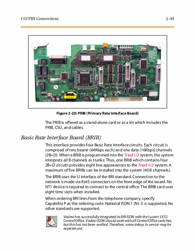
Primary Rate Interface Board (PRIB)This interface provides one Primary Rate Interface circuit. Each circuitcontains 23 bearer and one data channel (23B+D). When a PRIB card isprogrammed into the Triad 1/2 system, the system interprets allB channels as trunks. Thus, one PRIB which contains 23B+D circuitsprovides 23 line appearances to the Triad 1/2 system. A maximum of twoPRIB boards may be installed into the system. The PRIB card uses 24 timeslots when installed.
The PRIB must be used in conjunction with a Channel Service Unit (CSU).Connection is made via a DB15 from the PRIB to the CSU.
The PRIB accepts two DTMF-A boards.
When ordering PRI lines from the telephone company, specify ESFframing and B8ZS line coding. PRI only supports National ISDN 2 (NI-2).No other standards are supported.
Installation1. Insert the PRIB card(s) into the desired BKSU card slot(s). Up to two
PRIB cards can be installed in a system (Slots 1 and 2 on Triad 1 andslots 1-5 on Triad 2).
2. If installing a single PRIB, set SW2 to the ON position.
If multiple PRIBs are being installed, set SW2 to the ON position onthe first card and SW2 on all other cards to the OFF position.
The PRIB comes with a clock cable. This cable is used when multiplePRIB and/or digital trunk cards are to be installed in the system. Theclock cable is supplied with each PRIB.
3. Connect the DB15 cable from the PRIB to the channel service unit(CSU).
4. Connect the network cable from the channel service unit to thenetwork.
5. Refer to ISDN and T1 Clocking (later in this section) for clarification onclocking and cabling when combining BRIB, PRIB, and T1 cards in oneKSU.
Vodavi has successfully integrated its P RI ISDN w ith the Lucent 5 ESS,Siemens, Stromburg Carlson, and the DMS100 Central Offices. VodaviISDN should work with all Central Office switches, but this has not beenverified. Therefore, some delays in service may be experienced.
CO/PBX Connections 2-49
Figure 2-20: PRIB (Primary Rate Interface Board)
The PRIB is offered as a stand-alone card or as a kit which includes thePRIB, CSU, and cables.
Basic Rate Interface Board (BRIB)This interface provides four Basic Rate Interface circuits. Each circuit iscomprised of two bearer (64Kbps each) and one data (16Kbps) channels(2B+D). When a BRIB is programmed into the Triad 1/2 system, the systeminterprets all B channels as trunks. Thus, one BRIB which contains four2B+D circuits provides eight line appearances to the Triad 1/2 system. Amaximum of five BRIBs can be installed into the system (40 B channels).
The BRIB uses the U interface of the BRI standard. Connection to thenetwork is made via RJ45 connectors on the front edge of the board. NoNT1 device is required to connect to the central office. The BRIB card useseight time slots when installed.
When ordering BRI lines from the telephone company, specifyCapability P as the ordering code. National ISDN 1 (NI-1) is supported. Noother standards are supported.
Vodavi has successfully integrated its BRI ISDN with the Lucent 5 ESSCentralOffice.Vodavi ISDN should work withall CentralOffice switches,but this has not been verified. Therefore, some delays in service may beexperienced.

2-50 CO/PBX Connections
Installation1. Insert the BRIB card(s) into the desired BKSU card slot(s).
(Slots 1 and 2 on Triad 1 and slots 1-5 on Triad 2)
If installing a single BRIB, set switch 4 on SW2 to the ON position.
If multiple BRIB cards are being installed, set switch 4 on SW2 tothe ON position on the first card and switch 4 on SW2 on all othercards to the OFF position. Switch 4 on SW2 determines if theboard is the Master Clock source for any digital trunk cards in thesystem. Only one Master Source must be enabled in the system.
If installing a BRIB in a system that also has T1 or PRIB boards, useeither the T1 or PRIB card as the Master Clock and set all BRIB SW2switch 4s to OFF.
2. Refer to ISDN and T1 Clocking (later in this section) for clarification onclocking and cabling when combining BRIB, PRIB, and T1 cards in oneKSU.
Figure 2-21: BRIB (Basis Rate Interface Board)
ONOFF
SW2 SWITCHES: 2 3 41

CO/PBX Connections 2-51
Electronic Key Telephone ServiceElectronic key telephone service (EKTS) is a feature that can be providedon BRI ISDN to simulate standard analog DID lines. This allows severaldifferent numbers to be shared by a single BRI circuit.
Due to the decline in telephony tariffs, there is an increasing demand forBRI ISDN features. A BRI circuit allows two simultaneous calls to behandled, due to its technical specification. BRI circuits have twoB-Channels at 64 kilobytes per second and one D-Channel at 16 kilobytesper second. The Bearer (B) Channels are designed for PCM (voice) and theData (D) Channel is designed to carry information specific to eachincoming and/or outgoing call.
The EKTS feature allows a single ISDN Service Profile Identifier (SPID) orB-Channel to support multiple directory numbers. A SPID is a numberthat telephone company switching equipment uses to trackconfiguration information for each terminal adapter connected to anISDN telephone line. The telephone company should provide SPIDs atthe same time that the ISDN directory numbers are assigned. A directorynumber is another term for a telephone number.
If an application requires EKTS, be aware that BRI ISDN handles a busynumber differently than a DID circuit. When the called number is busy,BRI will issue a busy signal, but a DID circuit will ring another line in thecircuit. The busy signal is provided by the telephone company, thereforethe call is not presented to the Vodavi telephone switch and it is notforwarded to voice mail. For example, a caller dials 480-443-6000 and isconnected to the extension. While the first caller is still connected, asecond caller dials the same number. The second caller will receive a busysignal that is provided by the telephone company.
In a normal BRI application, two numbers are assigned to each BRI circuit,which consists of 2 channels. There can be a maximum of 4 circuitsequipped to handle 8 channels per BRIB. This is a direct number-to-channel relationship without hunting capability. Most circuit providersoffer an optional “hunting” feature capability on BRI circuits. This optionalfeature allows numbers to hunt for idle channels on the BRIB up to amaximum of 8 channels per BRIB, assuming four BRI circuits wereinstalled. In EKTS applications, you can have a maximum of 64 DIDnumbers hunt to one BRIB. Hunting cannot be accomplished betweenBRIBs, nor will the hunting feature allow calls to be routed to a busy DIDnumber.
2-52 CO/PBX Connections
ConditionsBRI EKTS support is available in Vodavi telephone systems with softwareversion 3.0G and higher.
Like DID, EKTS can be programmed to route calls using up to 7 digits. Bydefault, only the last three digits are analyzed for routing.
EKTS does not require a line appearance on a specific telephone becausethe BRI terminates directly into the KSU.
Vodavi supports Basic EKTS. The EKTS caching option is not supported byVodavi. Caching is normally used when an ISDN telephone instrument isused on the customer premise.
ISDN and T1 ClockingWhen combining BRIB, PRIB, and T1 cards in one KSU, specific settingsand cabling are important for proper clocking. The Phase Lock Loop Unit(PLLU) synchronizes the clocking from the Central Office to the clockingof the KSU. Popping, crackling, dropped calls, and one-way transmissionare usually attributed to the clocking not being synchronized correctly.
Examples - Settings and CablingThe following examples clarify the clocking and cabling for these cards:
When the switch is in the “up” position, it should be considered “ON”.When the switch is in the “down” posit ion, it should be considered “OFF”.
The cable connection follows the same logic - “up” is clock outside (ON)and “down” is clock inside (OFF). ON means thatclockingis comingfromoutside the KSU and OFF means that clocking is coming from inside theKSU.

CO/PBX Connections 2-53
(1) T1IB and (1)PRIB
If both cards in a phone switch are connected to a telephone companyclock (not point-to-point T1), put the T1 clock switch in the enableposition (UP) to allow it to receive clocking from the telephone companydirectly, and do not install the clock cable. Set the PRIB clock switch in thedisable position (OFF), which allows the PRIB to synchronize its timing offof the backplane (from the T1 clocking). If the T1 is a point-to-point T1,set the PRIB in the enable position (ON), the T1 in the disable position(OFF), and do not install the clock cable.
(1) PRIB and (1) BRIB
Install with the cable and set both PRIB and BRIB switches to the enableposition (ON).
T1IB PRIB
SW3 On SW2 Off
PRIB BRIB
Sw2 On Switch 4, SW2 On

2-54 CO/PBX Connections
(1) T1IB and (1) BRIB
If both cards in a phone switch are connected to a telephone companyclock (not point-to-point T1), put the T1 clock switch in the enableposition (ON) to allow it to receive clocking from the telephone companydirectly. Do not install the clock cable. Set the BRIB clock switch in thedisable position (OFF), which allows the BRIB to synchronize its timing offof the backplane (from the T1 clocking). If the T1 is a point-to-point T1,set the BRIB to the enable position (ON), the T1 in the disable position(OFF), and do not install the clock table.
(2) PRIBs and (3) T1IBs
The clock cable should be connected to the OUT position on theconnector on the PRIB1. The clock cable should be connected to the INposition on PRIB2. SW2 of the PRIB1 and PRIB2 should be placed in the
T1IB BRIB
SW3 On Switch 4, SW2 Off
PRIB1 PRIB2 T1IB1 T1IB2 T1IB3
SW2 On SW2 On SW3 Off SW3 Off SW3 Off

CO/PBX Connections 2-55
ON position. The three T1IBs are not connected with the clock controlcable and SW3 on these boards should be in the OFF position.
(3) T1IBs and (2) PRIBs
The clock cable should be connected to the OUT position on the cableconnector on the T1IB and connected to the IN position on the connectoron the T1IB2. The clock cable should be connected to the OUT positionon T1IB2 and connected to the IN position on the T1IB3. SW3 of T1IB1should be placed in the ON position, with SW3 on T1IB2 and T1IB3 beingOFF. The two PRIBs are not connected with clock control cables, and SW2on the PRIBs should be in the OFF position.
(3) PRIBs and (2) BRIBs
The clock cable should be connected from the OUT position of the PRIB1to the IN connectors of all the cards and all clock switches should be inthe ON position.
T1IB1 T1IB2 T1IB3 PRIB1 PRIB2
SW3 On SW3 Off SW3 Off SW2 Off SW2 Off
PRIB1 PRIB2 PRIB3 BRIB1 BRIB2
SW2 On SW2 On SW2 On Switch 4, SW2 On Switch 4, SW2 On

2-56 CO/PBX Connections
(3) T1IBs and (2) BRIBs
The clock OUT cable from T1IB1 should be connected to the clock INcable of the T1IB2 and the clock OUT cable from T1IB2 should beconnected to the clock IN cable of T1IB3. SW3 of T1IB1 should be in theON position, and SW3 of T1IB2 and T1IB3 should be in the OFF position.The two BRIBs are not connected with clock control cables and SW2 ofthe BRIB cards are placed in the OFF position.
T1IB1 T1IB2 T1IB3 BRIB1 BRIB2
SW3 On SW3 Off SW3 Off Switch 4, SW2 Off Switch 4, SW2 Off

Station Connections 2-57
Station Connections
The system can be equipped with any combination of the four stationboards; DTIB12, DTIB24, ETIB and SLIB6. The station interface boards canbe installed in any card slot in the BKSU and EKSU, except for MPB slot ofthe BKSU. As a default, the software allocates slots 1 through 5 of theBKSU and 9 through 10 of the EKSU for station interface boards. It isrecommended that slots beginning from SLOT #1 be used for stationinterface boards. Also, since the first port of the DTIB is the databaseaccess port (the only port which enables Admin programming), it isstrongly recommended that a DTIB be installed in the SLOT #1 and aDigital Keyset w/LCD be connected to the first port.
Electronic Telephone Interface Board (ETIB)The ETIB board provides the interface to twelve (12) electronictelephones or DSS/DTS terminals. The card has one LED indicator foroff-hook/in use status. The ETIB card extractors are color coded green.
There is one 50-pin female amphenol connectors labeled Conn2 locatedon the front of the card. This allows the system to be cabled to the maindistribution frame (MDF). 25-pair telephone cabling must be preparedwith mating connectors to extend the interface circuits to the MDF. Thecables should be routed through the cable clamps at the bottom of theKSU to the MDF. These cables are then terminated on industry standard66M1-50 type punchdown connector blocks. It is recommended that66M1-50 split blocks with bridging clips be used to simplifytroubleshooting and to quickly isolate faults.
Only DTIB type stations can be used for Database programming.

2-58 Station Connections
Table 2-11: ETIB Wiring
Pair PIN # Color Description Pair PIN # Color Description
1 261
WH/BLBL/WH
VT-1VR-1
CKT1 13 3813
BK/GNGN/BK
VT-7VR-7
CKT7
2 272
WH/OROR/WH
DT-1DR-1
14 3914
BK/BNBN/BK
DT-7DR-7
3 283
WH/GNGN/WH
VT-2VR-2
CKT2 15 4015
BK/SLSL/BK
VT-8VR-8
CKT8
4 294
WH/BNBN/WH
DT-2DR-2
16 4116
YL/BLBL/YL
DT-8DR-8
5 305
WH/SLSL/WH
VT-3VR-3
CKT3 17 4217
YL/OROR/YL
VT-9VR-9
CKT9
6 316
RD/BLBL/RD
DT-3DR-3
18 4318
YL/GNGN/YL
DT-9DR-9
7 327
RD/OROR/RD
VT-4VR-4
CKT4 19 4419
YL/BNBN/YL
VT-10VR-10
CKT10
8 338
RD/GNGN/RD
DT-4DR-4
20 4520
YL/SLSL/YL
DT-10DR-10
9 349
RD/BNBN/RD
VT-5VR-5
CKT5 21 4621
VI/BLBL/VI
VT-11VR-11
CKT11
10 3510
RD/SLSL/RD
DT-5DR-5
22 4722
VI/OROR/VI
DT-11DR-11
11 3611
BK/BLBL/BK
VT-6VR-6
CKT6 23 4823
VI/GNGN/VI
VT-12VR-12
CKT12
12 3712
BK/OROR/BK
DT-6DR-6
24 4924
VI/BNBN/VI
DT-12DR-12
25 5025
VI/SLSL/VI
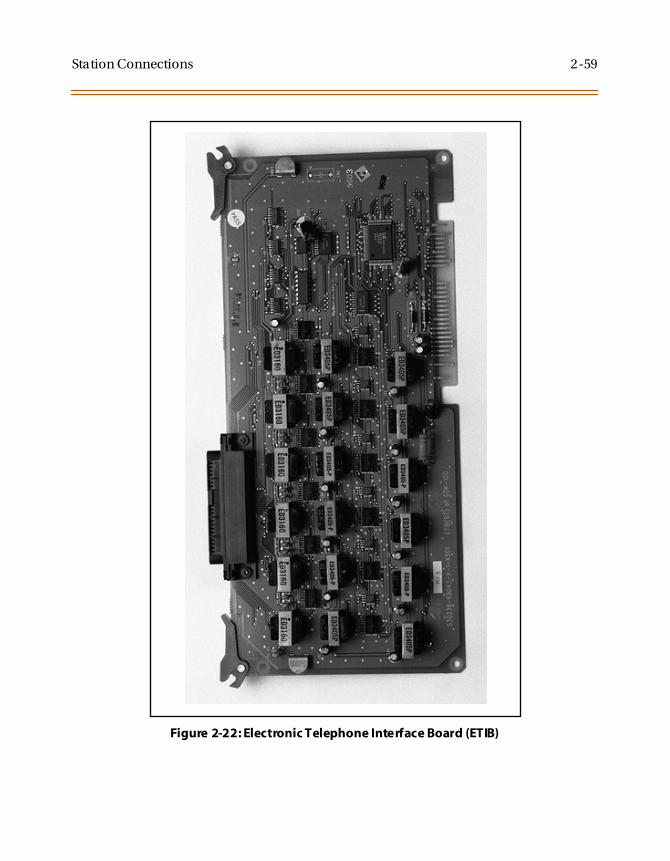
Station Connections 2-59
Figure 2-22: Electronic Telephone Interface Board (ETIB)

2-60 Station Connections
Single Line Interface Board (SLIB)This board provides the interface to six (6) 2500 type telephones. TheSLIB signals interface with mechanical 90V ringers and lights 90Vmessage waiting lamps on 2500 sets as desired.
The station connections are via three (3) Modular (RJ14 type) connectorslocated on the front edge of the card. The board can support a DTRUboard and a MSG12 board in a daughter board type arrangement.
The DTRU unit has two (2) DTMF receivers on it and can be installed onthe SLIB board. The DTRU mounts on the SLIB board as a daughter boardtype arrangement.
Only one SLT station is allowed per digital extension number. It is notpossible to bridge digital station ports so that an extension number mayappear in more than one location.
Table 2-12: SLIB Wiring
SLIB Connector
Connector Pin # 3M Connection 6M Connection
M3 3 Tip 6 Tip 6
2 Ring 6 Ring 6
4 Tip 5 Tip 5
1 Ring 5 Ring 5
M2 3 Tip 4 Tip 4
2 Ring 4 Ring 4
4 Tip 3 Tip 3
1 Ring 3 Ring 3
M1 3 Tip 2 Tip 2
2 Ring 2 Ring 2
4 Tip 1 Tip 1
1 Ring 1 Ring 1

Station Connections 2-61
Installing the DTRU Module1. Unpack the DTRU Module from its antistatic conductive bag in the
packing box.
2. Locate the CON1 and CON2 connectors on the DTRU module.
3. Locate the CONN1 and CONN2 connectors on the SLIB (outlined).
4. Position the DTRU module so that the CON2 and CON1 connectorsmatch up with the CONN1 and CONN2 connectors on the SLIBrespectively.
5. Push the DTRU module onto these connectors making sure it isseated properly.
Refer to Figure 2-23. This completes the installation procedure for theDTRU Module.
Installing the MSGU BoardThe Message Wait Lamp Relay Control (MSGU) provides Message WaitLamp Relay Control for message lamp single line telephones. The MSGUboard mounts on the SLIB board as a daughter board type arrangement.
1. Unpack the MSGU Module from its antistatic conductive bag in thepacking box.
2. Locate the CONN1 and CONN2 connectors on the MSGU module.
3. Locate the CONN3, and CONN4 connectors on the SLIB (outlined).
4. Position the MSGU module so that the CONN1 and CONN2connectors match up with the CONN3 and CONN4 connectors on theSLIB respectively.
5. Push the MSGU module onto these connectors making sure it isseated properly.
Refer to Figure 2-23. This completes the installation procedure for theMSGU Module.

2-62 Station Connections
Adjusting Modem SettingsWhen using modems connected to SLT ports on the Triad 1/2/3, the gainsettings on the SLT port when using T1 as access to the CO should be setto 0 dB (maximizes modem speed).
CO to SLT Call via a T1 TIE Trunk:1. Access the specific trunk type above.
2. Hookflash and dial 638 8 on the keypad.
3. Hang up.
CO to SLT Call via a T1 Trunk:1. Access the specific trunk type above.
2. Hookflash and dial 638 6 on the keypad.
3. Hang up.
SLT to SLT Call:1. Place an intercom call from 1 SLT to another.
2. Hookflash and dial 638 5 on the keypad.
3. Hang up.
No adjustment is needed if access to the CO is accomplished by standardloop/ground start trunk circuits. These trunk types are set to 0 dB bydefault.
In all cases the maximum modem speed is not as much as if the modemwere connected directly to the CO line. The system degrades theconnection to the next lower baud rate that the modem supports.Example: If the modem can achieve 28800 on a direct CO line, themaximum speed on an SLT port would be 26400.
Testing proves that a baud rate of 33600 can be achieved with SLT-T1lines. Typical connection speeds with SLT-T1 are 22700-33600. Typicalconnection speeds with SLT-Loop/Ground Start are 17400-23800.
All results w ere obtained using a 56K U.S. Robotics Sportster modem.

Station Connections 2-63
Figure 2-23: SLIB w/MSGU and DTRU Module Installation
DTRU
CON2
CON1
CON
N3
CON
N4
CONN1
CONN2
CONN1
MSGU

2-64 Station Connections
Digital Telephone Interface Board (DTIB)The DTIB board provides the interface to twelve (12) digital telephones. Itis offered in two (2) versions, a 12-circuit and a 24-circuit. The card hasone LED to indicate off-hook/in use status. The DTIB card extractors arecolor coded green.
Cables
There is one 50-pin female amphenol connectors labeled Conn2 locatedon the front of the card. This allows the system to be cabled to the maindistribution frame (MDF).
25-pair telephone cabling must be prepared with mating connectorsto extend the interface circuits to the MDF.
Cables should be routed through the cable clamps at the bottom ofthe KSU to the MDF. These cables are then terminated on industrystandard 66M1-50 type punchdown connector blocks.
It is recommended that 66M1-50 split blocks with bridging clips beused to simplify troubleshooting and to quickly isolate faults.
Only one stationisallowedperdigitalextension num ber. It is notpossibleto bridge digital station ports so that an extension number may appearin m ore than one location.

Station Connections 2-65
Table 2-13: DTIB Wiring
Pair PIN # Color Description Pair PIN # Color Description
1 261
WH/BLBL/WH
DATA-R 1DATA-T 1
DTI
B1
2S
tati
on
Por
ts
13 3813
BK/GNGN/BK
DATA-R 13DATA-T 13
DTI
B2
4S
tati
on
Por
ts
2 272
WH/OROR/WH
DATA-R 2DATA-T 2
14 3914
BK/BNBN/BK
DATA-R 14DATA-T 14
3 283
WH/GNGN/WH
DATA-R 3DATA-T 3
15 4015
BK/SLSL/BK
DATA-R 15DATA-T 15
4 294
WH/BNBN/WH
DATA-R 4DATA-T 4
16 4116
YL/BLBL/YL
DATA-R 16DATA-T 16
5 305
WH/SLSL/WH
DATA-R 5DATA-T 5
17 4217
YL/OROR/YL
DATA-R 17DATA-T 17
6 316
RD/BLBL/RD
DATA-R 6DATA-T 6
18 4318
YL/GNGN/YL
DATA-R 18DATA-T 18
7 327
RD/OROR/RD
DATA-R 7DATA-T 7
19 4419
YL/BNBN/YL
DATA-R 19DATA-T 19
8 338
RD/GNGN/RD
DATA-R 8DATA-T 8
20 4520
YL/SLSL/YL
DATA-R 20DATA-T 20
9 349
RD/BNBN/RD
DATA-R 9DATA-T 9
21 4621
VI/BLBL/VI
DATA-R 21DATA-T 21
10 3510
RD/SLSL/RD
DATA-R 10DATA-T 10
22 4722
VI/OROR/VI
DATA-R 22DATA-T 22
11 3611
BK/BLBL/BK
DATA-R 11DATA-T 11
23 4823
VI/GNGN/VI
DATA-R 23DATA-T 23
12 3712
BK/OROR/BK
DATA-R 12DATA-T 12
24 4924
VI/BNBN/VI
DATA-R 24DATA-T 24
25 5025
VI/SLSL/VI

2-66 Station Connections
Figure 2-24: Digital Telephone Interface Board (DTIB) Installation

System Wiring 2-67
System Wiring
Battery Back-Up Wiring InstallationThe system can be equipped to provide operation from external batteriesif local AC power fails. The Back-Up batteries are connected to the stripconnector on the front of the PSU as shown:
Figure 2-25: Battery Back-Up Wiring
The external batteries must provide 24 Volts DC. This is generallyaccomplished by connecting two 12 volt batteries in a seriesarrangement. Operation on batteries is controlled by the PSU. This PSUprovides charging current to the batteries during normal AC poweroperation at a maximum of about 1 amp.
During battery operation, the PSUs discontinue battery operation if theAC power is reapplied or the battery voltage is too low to maintainproper system operation. If a low-battery cut-off occurs and a newbattery is installed, it is necessary to reset the Battery Back-Up circuit inthe PSU manually by momentarily depressing the white colored BATT.RESTART switch located on the faceplate of the PSU.
- +
+ -
+MARKER
-MARKER
+
PSU
-
4 PINCONN
BATT

2-68 System Wiring
The length of time the system operates on the batteries is dependent onseveral elements including: battery charge state, condition of thebatteries, capacity of the batteries, and the size of the system (number ofstation ports).
The following chart gives the approximate back-up time for severalsystem sizes and different battery capacities in ampere-hours.
MPB and SIU RS232C Port WiringThe MPB has one standard RS232C port and the SIU has two standardRS232C ports. The RS232C ports are connected by 9-pin D connectors asshown in Figure 2-26. Note the configuration is 8 bits, no parity and 1 stopbit.
Figure 2-26: RS232 9-Pin Connector Wiring
Table 2-14: System Back-Up Duration
Battery Capacity 36 Ports 60 Ports
20AH 4 Hour 1.75 Hour
40AH 8 Hour 3.5 Hour
MPB & SIURS232C
9 PIN
TERMINAL
9 PIN
2 ( TX)
3 (RX)
5 (GND) 5 (GND)
2 (RX)
3 ( TX)
9 PIN 25 PIN
2 ( TX)
3 (RX)
5 (GND) 5 (GND)
3 (RX)
2 ( TX)

System Wiring 2-69
MISU WiringThe MISB has connections for 2 music sources, 2 External page zones and4 relay contact controls. The MISB connections are made by the 25 pairconnector. The wiring connections for the 25-pair cable are identified inTable 2-2.
Station WiringStation interface boards (DTIB, ETIB, SLIB) includes a 25 pair connector forstation wiring to the ports on the board. The following provides detailson the interconnection of each type of station interface board and thestation jack.
Digital Keyset and Terminal WiringWiring from the DTIB to station jack requires one pair of wire. Digitizedvoice, signaling, and power are sent over this pair.
Figure 2-27 gives details on connections of station jacks to the system andTable 2-13 gives the configuration of the 25-pair station connectorarrangement and punchdown type block.
Figure 2-27: Digital Station Jack Wiring
Only the first pair (Red, Green on jack) should be connected back to theKSU. No other pairs should be connected back to the KSU.
G
Y
R
BK
DR (RED)
DT (GREEN)

2-70 System Wiring
Electronic Keyset and Terminal WiringWiring from the ETIB to station jack requires two pairs of wire. The firstpair provides the audio or voice path, the second is for signaling or datapath. The DATA pair is polarity sensitive, reversal does not harm thekeyset or system, but the port does not function properly when reversed.Power is delivered by applying DC voltage to the center tap of thecoupling transformers of each of the 2 pairs.
Figure 2-22 gives details on connections of station jacks to the system andTable 2-11gives the configuration of the 25-pair station connectorarrangement and punchdown type block.
Figure 2-28: Electronic Station Wiring
G
Y
R
BK
VR (RED)
VT (GREEN)
DR ( YELLOW)
DT (BLACK)

System Wiring 2-71
Single Line Telephone WiringThe SLIB is wired to SLT devices with a single pair of wire which providesbattery feed, voice and signaling to and from the SLT. Typical wiring tothe SLT jack is shown in Figure 2-29 and Table 2-12gives the configurationof the station connector arrangement when connected to a punchdowntype block.
Figure 2-29: Single Line Telephone Wiring
G
Y
R
B
VR
VT

2-72 System Wiring
Power Failure Transfer WiringThe PFTU is wired from the 25-pair connector to the MDF, crossconnected to the CO Line inputs from the telephone company, to the COLine inputs of the system, and to Power Failure SLTs. The basicconnections are shown in Figure 2-30 and the connector configuration isgiven in Table 2-12. Note that the SLT may also be connected to a SLIB asshown in the figure.
Figure 2-30: PFTU Wiring
MDF (PFTU)
COR1-IN
COT1-IN
COR1-OUT
COT1-OUT
TEL1-R
TEL1-T
SLIB1-R
SLIB1-T
126
CO L1CO L2
227LCOB
328SLT
429
SLIB24Subscriber

Wall Mounting the Electronic Telephone 2-73
Wall Mounting the Electronic Telephone
All connections to the Electronic Key Telephone are fully modular. To wallmount the Electronic Key Telephone, it is necessary to have one WallMount Kit and one standard-type jack assembly designed for normal wallhanging applications.
1. Unplug the line cord from the phone. This line cord is not be requiredand should be retained as a maintenance replacement item.
2. Lift the plastic number retainer upward and expose the screwunderneath. Remove the screw and the handset tab. Replace it withthe handset tab from the Wall Mount Kit.
3. Be careful to position the tab so that the protrusion faces thehookswitch. This allows the handset to remain secure when thetelephone is on the wall. Replace the screw and snap the numberretainer into place.
4. Substitute the short modular cord from the Wall Mount Assemblyinto the modular connector vacated by the line cord.
5. Align the wall mount baseplate with holes on the bottom of thetelephone. Snap in place.
6. Now match the two key hole slots on the baseplate with the lugs onthe 630-A type jack. Align the modular connector and slide telephoneinto place. Refer toFigure 2-33.
2-74 Wall Mounting the Digital Telephone
Wall Mounting the Digital Telephone
To wall mount the Digital Key Telephone, it is necessary to use the WallMount bracket and one standard-type jack assembly designed for normalwall hanging applications. Refer to Figure 2-33 and Figure 2-34.
1. Remove the handset from the cradle and locate the plastic retainer inthe bottom of the hook-switch well area. Push the plastic retainerslowly upward until it is free. Locate the tab on the plastic retainerand make sure the tab is toward you, then place it back into its holder.Slide the plastic retainer all the way down into its channel. Part of theretainer remains above its holder to hold the handset secure for thewall mount configuration.
2. Turn the telephone over and unplug the line cord. If the line cord isnot plugged into the wall jack assembly, re-route the line cord thruthe access channel on the top of the telephone. If the line cord isplugged into the wall jack assembly, run the line cord through thehole provided and plug into the connector on the back of thetelephone.
3. Line up the hooks on the top and bottom of the wall mount bracketso they can engage with the slots cut into the bottom of thetelephone base. Insert the bottom hooks first. Slide the mountingbracket slowly downwards until the top tabs slide into the top slotsand snap in place.
4. Match the two key hole slots on the base plate with the lugs on the630-A type jack. Align the modular connector and slide the telephoneinto place.
5. Place the handset onto the retainer. The telephone is now ready foruse. Refer to Figure 2-34 for location of mounting information.

Headset Installation 2-75
Headset InstallationThe Triad 1/2/3 Electronic/Digital Key Telephones have been designed tooperate with industry standard electret mic compatible modular headsetadapters and operator headsets.
To modify an Electronic/Digital Key Telephone to support an externalheadset:
1. Plug the headset adapter cord into the vacant handset jack on theKey Telephone base.
2. Plug the telephone handset cord into the headset adapter box whereindicated by the headset manufacturer's instructions.
The Headset Operation must be enabled (refer to Station Programming).The station then has the capability to enable/disable headset mode bydialing a code. When Headset mode is active at the station, the ON/OFFbutton controls the on-hook or off-hook status. Also, features such asOn-Hook Dialing and Handsfree Speakerphone operation becomeinoperable.
Caller ID Interface Unit InstallationThe Caller Identification Interface Unit receives the data from thetelephone company and sends the data, in ASCII RS-232C format to aprinter, telephone, computer or DTE (Data Terminal Equipment) device.
Selecting the Cable1. Select the correct RS-232 cable (P/N 9081-00) for the
Triad 1/2 MPB and SIU.
2. Connect one end of the cable on the desired KSU I/O port (1, 3, or 4).
3. Connect the other end to the OUT port on the Caller ID unit.

2-76 Caller ID Interface Unit Installation
Figure 2-31: Caller ID Cable Connections
Triad 1/2 MPBand SIU
KSU 9-PinFemale Connec tion
1440/1480-009-Pin Male
1 1
2 2
3 3
4 4
KSU 5 5 Caller ID Box
6 6
7 7
8 8
9 9
1480-00 Switch SettingsONOFF
1440-00 Switch SettingsONOFF
1627
849
5
3
Y E L L O W
R E D
87654321
P 1
XX
X
XXX
XX
X
XX
I C L I D E N DR J 4 5
J 187654321
87654321
J 3 J 4
T O C P U
R J 4 5 R J 4 5
87654321
11 421 531 641 751 861 972 082 192 21 02 31 12 41 22 51 3
R J 4 5
J 2Y E L L O W
R E D
XX
XXX
X
XX
XXXXXXXXX
XXXXXXXXXXXX
K S U E N D
C O N N E C T O R D B 2 5
D i g i - K e y H 2 8 8 3 - 1 4 - N D S t r a i g h t t h r u C a b l e ( D i g i - K e y R e v e r s e )
D B 9 t o R J 4 5 A d a p t e r D B 2 5 t o R J 4 5 A d a p t e r
T o R S - 2 3 2 B c D B 2 5P 2
N O T E :
1 . C u t a l l o t h e r w i r e s b a c k i n t h e a d a p t e r s s o t h a t n o n e o f t h e m s h o r t t o e a c h o t h e r o r t h e c o n n e c t o r s .2 . U s i n g t w o o f t h e c u t - o f f w i r e s , s t r i p t h e i n s u l a t i o n o f t h e c u t e n d b a c k f a r e n o u g h ( 1 / 2 i n c h ) t o s o l d e r t o g e t h e r .3 . I n s e r t t h e c o n n e c t o r p i n s i n t o L o c a t i o n s 7 a n d 8 o f t h e D B 9 c o n n e c t o r ( P 1 ) .4 . I n s u l a t e t h e s o l d e r j o i n t w i t h t a p e o r h e a t s h r i n k t u b i n g .
1 4 8 0 C A L L E R I D C A B L E
I C L I D C A B L E P I N O U T D I A G R A M F O R 1 4 2 8 / 4 8 9 6 / D V X I / D V X 3
NOTES:
1. Cutall other wires in the adapters so that none of them short to each other orthe connectors.2. Using two of the cut-off wires,strip the insulation of the cut end back farenough (1/2 inch) to soldertogether.3. Insert the connector pins into Locations 7 and 8 of the DB9 connector (P1).4. Insulate the solder joint with tape or heat shrink tubing.
ICLID Cable Pin-Out DiagramRJ45/DB9/RS232

Caller ID Interface Unit Installation 2-77
Programming the KSU
I/O Ports1. Verify the programming for the I/O ports, press ✳✳3226, Flash 15.
2. Select the desired I/O port, Button 1, 3, 4 (MPB, SIU1, SIU2).
3. Dial [5] on the dial pad and press HOLD.
CO Lines1. Verify the programming for the CO Lines, press ✳✳3226, Flash 40.
2. Enter CO line Range for the Caller ID Unit and press HOLD.
3. Press Button 21 (Page C).
4. Press Button 2, Ring Delay Timer.
5. Enter 04 (minimum). Press HOLD.
6. Reset the system and the CTI box.
Figure 2-32: CTI System Configuration
CO LINES
ICLIDInterface
Unit
ICLIDInterface
Unit
RS232
STARPLUSKSU
RS232
LANSERVER
CTIModule
CTIModule
CTIModule
LAN
LAN
LAN
LAN

2-78 Caller ID Interface Unit Installation
Figure 2-33: Electronic Key Telephone Wall Mounting

Caller ID Interface Unit Installation 2-79
Figure 2-34: Digital Key Telephone Wall Mounting

2-80 Caller ID Interface Unit Installation
Figure 2-35: SMDR Printout
The SMDR feature provides detailed records of al l outgoing and/or incoming, long distance only or allcalls. The SMDR Quali fication Timer determines the leng th of time that is needed to determine a validSMDR cal l for reporting purposes. By default, this timer is set to 30 seconds and is variable from 00 to 60seconds in 1 sec. increments. This feature is enabled or disabled in system programming. By default,SMDR is not enabled and is set to record long distance calls only. A printout format of 80 charactersmaximum or 30 character maximum may be selected in system programming. The standard format is 80characters on a single line. A 30 character format generates 3 l ines per message. If the SMDR feature isenabled, the system starts collecting information about the call as soon as it starts and terminates whenthe cal l ends. I f the call was longer then 30 seconds, the following information is printed:
30 charac ter format selected:
1 2 3123456789012345678901234567890AAAA BBB HH:MM:SS HH:MM MM/DD/YY(CR)(LF)HCCCCCCCCCCCCCCCCCCCCCCCCCCC<R>GGGGGGGGGGGG
STA CO TOTAL START DATE1116 008 00:02:00 14:13 08/28/00(CR)(LF)0123456789012345678901234(CR)(LF)123456789012(CR)(LF)
80 charac ter format selected:
1 2 3 4 5 6 7 812345678901234567890123456789012345678901234567890123456789012345678901234567890AAAA BBB HH:MM:SS HH:MM MM/DD/YY HCCCCCCCCCCCCCCCCCCCCCCCC GGGGGGGGGGGG (CR)(LF)
STA CO TOTAL START DATE DIALED ACCOUNT CODE<_><_>COST1116 008 00:02:00 14:13 08/28/00 O123456789012345678901234 123456789012(CR)(LF)
80 charac ter format with Call Cost Display feature enabled:
1 2 3 4 5 6 7 812345678901234567890123456789012345678901234567890123456789012345678901234567890AAAA BBB HH:MM:SS HH:MM MM/DD/YY HCCCCCCCCCCCCCCCCCCCCCCCC GGGGGGGGGGGG (CR)(LF)
STA CO TOTAL START DATE DIALED ACCOUNT CODE<~><~>COST1116 008 00:02:00 14:13 08/28/00 O123456789012345678901234 123456789012<_>000.00(CR)(LF)
80 charac ter format for DISA Calls:
1 2 3 4 5 6 7 812345678901234567890123456789012345678901234567890123456789012345678901234567890AAAA BBB HH:MM:SS HH:MM MM/DD/YY HCCCCCCCCCCCCCCCCCCCCCCC GGGGGGGGGGGG (CR)(LF)
STA CO TOTAL START DATE DIALED ACCOUNT CODE<~><~>COST1116 001 00:02:00 14:13 08/28/00 I 123456789012<_>000.00(CR)(LF)001 004 00:04:54 14:15 08/28/00 I0123456789012345678901234 - continued on next page -

Caller ID Interface Unit Installation 2-81
ICLID 30 character format selected:
1 2 3123456789012345678901234567890STA CO TOTAL START DATE1000 001 00:00:19 09:32 08/28/00(CR)(LF)O 480-443-6000(CR)(LF)123456789012 **(CR)(LF)
ICLID 80 character format selected:
1 2 3 4 5 6 7 812345678901234567890123456789012345678901234567890123456789012345678901234567890STA CO TOTAL START DATE DIALED ACCOUNT CODE<_><_>COST1000 001 00:00:36 04:37 08/28/00 I1-480-443-6000 **(CR)(LF)
**VODAVI (CR)(LF)01 00:00:00 04:38 08/28/00 U1-480-443-6000 **
**VODAVI (CR)(LF)
- AAAA = Station originator or Trunk on DISA and Off-Net (CO Line) calls.
- BBB = Outside line number
- HH:MM:SS = Duration of call in Hours, Minutes and Seconds
- HH:MM = Time of day (start time) in Hours and Minutes
- MM/DD/YY = Date of Call
- H = Indicates cal l type:“I” = Incoming*“O” = Outgoing“T” = Transferred*“U” = Unanswered calls for ICLID SMDR call records
- CC....CC = Number dialed
- GG....GG = Last Account code entered (optional)
- (CR) = Carriage return
- (LF) = Line Feed
Figure 2-32: SMDR Printout

2-82 Caller ID Interface Unit Installation

3 Triad 3 SystemInstallation
This chapter contains the basic system installation and wiringinstructions for the Triad 3 System, as well as how to install theoptional cards and units.


Introduction 3-3
Introduction
As with any sophisticated communications device, installation of theSTARPLUS Triad 3 System, requires the care and forethought of acompetent technician. To assure easy servicing and reliable operation,several factors must be considered when planning the systeminstallation. The installation proceeds in these major steps:
Site Preparation
KSU and Power Supply (PS) Installation
PCB Installation
System Wiring
Keyset & Terminal Installation
Basic Installation Check-Out
System Programming and Verification
Installing the STARPLUS Triad 3 System is quick and efficient if theseinstallation instructions are followed.
Site Preparation
General Site ConsiderationsThe first step is to locate an acceptable site for the common equipment(KSUs, boards, etc.). When locating a mounting site for the KSUs, thefollowing points must be considered.
The KSUs are designed for wall mounting and should not bemounted directly to a masonry or plasterboard wall. It isrecommended that a 1/2 inch plywood back board be firmlymounted to the wall, and the KSU and MDF be mounted to the backboard. Each BKSU/EKSU1 must have its own 110 Volt AC circuit andcircuit breaker.

3-4 Site Preparation
The location must have access to a dedicated 110 Volt AC (±10%), 60Hz, single-phase circuit with a circuit breaker or fuse rated at 15 amps.A 3-wire (parallel blade grounded outlet should be withinapproximately 6 feet of the lower left rear of the BKSU mounting.
The location must have access to a good earth ground, such as ametallic cold water pipe with no non-metallic joints. The groundsource should be located as close as possible to the system.
The system should be located in an area which is well ventilated witha recommended temperature range of 68°-78° F and a relativehumidity range of 5-60% (non condensing).
The system should be located within 25 feet of the telephonecompany ’s termination point. Also, the location should be within theprescribed station loop lengths for all keysets and terminals. Ifexisting cabling is to be used, the location of existing cabling andconduits should be considered.
Protection from flooding, flammable materials, excessive dust andvibration.
Proximity of radio transmitting equipment, arc-welding devices,copying machines and other electrical equipment that are capable ofgenerating electrical interferences. Operation of this equipment in aresidential area is likely to cause interference in which case the user,at their own expense, is required to take whatever measures may berequired to correct the interference.
Back-Board InstallationA wooden back-board is recommended for all installations and must beinstalled when the location has masonry or plasterboard walls. A 1/2 inchplywood material is sufficient for most installations. The back-boardshould be mounted at a convenient height, about 3 feet above the floorand bolted in a number of places to distribute the weight of the system.
Space should be available on the right side of the back-board for the MDFcabling and for optional equipment such as a music source. It isrecommended the location of each major item be roughly sketched onthe back-board as an installation layout.

Site Preparation 3-5
Verify On-Site EquipmentOnce the equipment installation site has been identified and a dedicatedAC outlet, earth ground, and lighting and ventilation are available, verifythat all equipment required is on-site and has not been damaged duringshipment. Unpack the KSUs and the PSUs and assure there is no shippingdamage.
A mounting template is packed with each KSU, and this template isrequired later in the installation. Check that the type and quantity ofboards receive is correct and optional equipment and a Power Line SurgeProtector are on-site.
The individual boards SHOULD NOT be unpacked at this time. If anyequipment is damaged or missing, notify the appropriate personnel tocorrect the situation.

3-6 Site Preparation
Figure 3-1: Basic Cabinet (BKSU) w/Expansion KSU (EKSU1/EKSU2)
In certain configurations, it is possible to not have all card slots utilized due to powercapacities. Use the Configurator Program to calculate the correct configuration.

KSU & Power Supply (PSU) Installation 3-7
KSU & Power Supply (PSU) Installation
The system consists of a maximum of two cabinets that can be stackedtogether. The first cabinet, or Basic KSU (BKSU), houses the commonequipment boards and peripheral equipment boards. The Expansioncabinet (EKSU2) mounts to the right of the BKSU.
The card slots in Expansion cabinet houses only peripheral boards. Anyarrangement of CO Lines, Stations, etc. is permitted. The system size islimited to the ports available and can be configured in accordance withcustomer requirements. The cabinets are wall mountable.
Mounting the Basic KSUUsing the KSU mounting template provided with the BKSU, mark thelocation of the four screws to mount the BKSU. Again, the KSU must NOTbe mounted on a masonry or dry-wall surface, in this case a woodenback-board is required. Refer to Figure 3-2 for the distance betweenmounting holes.
The BSKU is mounted with four #10 or larger, 1 ½ inch or longer screws.
1. Drill pilot holes in the four locations marked.
2. Insert the screws and tighten leaving about ½ inch exposed.
3. Mount the Basic KSU on the screws and tighten the screws securely.
4. Remove the front cover by turning the two front cover screws ½ turncounter clockwise.
5. Tilt and lift the cover to remove.
(All packing material should be removed from the inside of the KSU.)
All cabling for boards exit the BKSU from an opening on the right sideof the KSU. Care should be taken to ensureenough length is providedtoalsopass thru the EKSU as ALL cables mustexit the opening in the EKSUwhen installed.
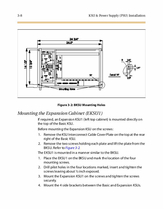
3-8 KSU & Power Supply (PSU) Installation
Figure 3-2: BKSU Mounting Holes
Mounting the Expansion Cabinet (EKSU1)If required, an Expansion KSU1 (left top cabinet) is mounted directly onthe top of the Basic KSU.
Before mounting the Expansion KSU on the screws:
1. Remove the KSU Interconnect Cable Cover Plate on the top at the rearright of the Basic KSU.
2. Remove the two screws holding each plate and lift the plate from theBKSU. Refer to Figure 3-2.
The EKSU1 is mounted in a manner similar to the BKSU.
1. Place the EKSU1 on the BKSU and mark the location of the fourmounting screws.
2. Drill pilot holes in the four locations marked, insert and tighten thescrews leaving about ½ inch exposed.
3. Mount the Expansion KSU1 on the screws and tighten the screwssecurely.
4. Mount the 4 side brackets between the Basic and Expansion KSUs.

KSU & Power Supply (PSU) Installation 3-9
5. Remove the front cover by turning the two front cover screws ½ turncounter clockwise.
6. Tilt and lift the cover to remove.
The KSUs require intercommunications which are provided by the KSUData Cable shipped with each EKSU.
1. Connect the cable to the back plane of both KSUs by a 25-pairconnector.
2. Install the cable through the Basic KSU where the Cable Cover Platewas removed into the Expansion KSU.
3. Insert the 25-pair connector at each end of the cable in the connectoron the back plane of each KSU.
Mounting the Expansion Cabinet (EKSU2)The Expansion KSU2 is mounted directly on the right of the BKSU.
1. Before mounting the Expansion KSU2 on the screws, remove the KSUInterconnect Cable Cover Plate on the right side at the rear right ofthe BKSU.
2. Remove the two screws holding each plate and lift the plate from theBKSU. (Refer to Figure 3-2.)
3. Mark the location of the four mounting screws.
4. Drill pilot holes in the four locations marked, insert and tighten thescrews leaving about ½ inch exposed.
5. Mount the Expansion KSU on the screws and tighten the screwssecurely.
The KSUs require intercommunications which are provided by theKSU Data and Power Cables shipped with each EKSU2. The KSU cableis connected to the back plane of both KSUs by a 25-pair connectorand 20 wires power cable.

3-10 KSU & Power Supply (PSU) Installation
Figure 3-3: Expansion Cabinet (EKSU2) Installation

Ring Generator Installation (RGU) 3-11
Ring Generator Installation (RGU)
This unit is needed in the BKSU, whenever SLT devices are installed onthe system. This unit supplies the ring voltage and message wait voltagefor the operation of SLTs on the system.
The system provides the capability to have an optional ring generator(RGU) for signaling 2500 type telephones and providing message waitingon 2500 type telephones.
Figure 3-4: Ring Generator Installation

3-12 KSU Grounding
KSU Grounding
To ensure proper system operation and for safety purposes, a good earthground is required.
A metallic COLD water pipe usually provides a reliable ground path.Carefully check that the pipe does not contain insulated joints that couldisolate the ground path. In the absence of the COLD water pipe, a groundrod or other source may be used.
A #14 Insulated AWG or larger copper wire should be used between theground source and the KSU. The wire should be kept as short as possible,it is recommended that the wire be no longer than about 25 feet.
Grounding Instructions1. Remove about 1½ inches of insulation from both ends.
2. Attach one end of the wire to the Ground Lug in the middle of theBasic KSU by inserting the wire under the lug screw and tighten thescrew securely. Refer to Figure 3-5. Attach the other end of the wire asappropriate to the ground source.
3. Take a DC resistance reading and an AC Volt reading between thechassis ground point (cold water pipe) and AC ground (third wire ACground). The limit is 5V AC and 5 Ohms DC resistance. If a higherreading is obtained, choose a different chassis ground point andrepeat this step until a suitable ground point is found.
Grounding to an electrical conduit is NOT considered a goodground!

KSU Grounding 3-13
Figure 3-5: KSU Grounding
(#14 InsulatedWire)
GNDGround Lug
BKSU Front View

3-14 Power Supply Unit Installation
Power Supply Unit Installation
AC/DC (PS-10A or PS-15A)There are two power supply units, one with a 10A (output) rating, theother with a 15A (output) rating. The power supply connects to theDC/DC Converter Unit (DCCU) located in the BKSU cabinet.
The BKSU/EKSU1 cabinets are powered with a separate power supplies.These power supplies should be able to support its associated cabinet ina heavily loaded configuration of station instruments.
The BKSU/EKSU1 cabinets can each house two (2) power supplies. Thepower supplies convert AC to 24V DC.
The PSU can operate from either 115 or 230 volts AC based on the settingof the VTG Selector Switch on the lower front of the PSU. If local AC is 110volts, move the switch to the right to display 115V. If local AC is 230 volts,move the switch to the left to display 230V.
Although, the Triad 3 System PSUs are equipped with power-linetransient protection, an external Power Line Surge Protector should beinstalled at the AC outlet to give additional protection, especially duringviolent thunderstorm activity.
Refer to Power Line Surge Protection.

Power Supply Unit Installation 3-15
Figure 3-6: AC/DC Power Installation

3-16 Power Supply Unit Installation
DC/DC (with BCU & 48VU)The BKSU/EKSU1 cabinets have a separate DC/DC Power supply. Thispower supply should be able to support its associated cabinets in aheavily loaded configuration of station instruments. The power supplyconnects from the AC/DC located in the BKSU.
-48V Supply Unit (48VU) - The DC/DC have an optional -48V supply unit(48VU) to the system to support certain trunks and SLT station. Thesystem can supply -48V DC up to 1.5A amp per KSU. If 1.5A amp isexceeded in a KSU, an external -48v source must be used. Connectionsare made on the front panel of each KSU.
Installing Optional Battery Charging Unit (BCU)The DC/DC Converter (DCCU) has an optional Battery Unit to providecharging of external batteries and the circuitry to support switchover tobattery operation with no loss of system operation. Connections aremade on the front panel of each KSU. The batteries are charged at arating of 1 amp./per cabinet.
1. Remove the four screws on the DCCU and remove the cover. Unpackthe Battery Charging Unit. There should also be a cable and fourscrews in the package. Locate the four screw locations on the DCCUwhere the BCU card is installed. Refer to Figure 3-7.
2. Place the BCU board so that the Molex connector is below theconnector labeled TO BCU on the DCCU motherboard. Screw the BCUinto place. Refer toFigure 3-8.
3. Attach one end of the BCU cable to the connector on the BCU boardand the other end to the connector labeled TO BCU.
4. Replace the cover and screws back onto the DCCU. Insert DCCU intothe BKSU.

Power Supply Unit Installation 3-17
Figure 3-7: Optional Battery Charging Unit (BCU)

3-18 Power Supply Unit Installation
Figure 3-8: DCCU and Optional BCU Installation

Power Supply Unit Installation 3-19
Refer to Figure 3-1 for a list of all card types.
Table 3-1: Power Consumption per Card
Card Power Required
10A Power Supply provides 240 watts15A Power Supply provides 360 watts
Digital Telephone Interface Bd (DTIB) 38 watts*
Digital Telephone Interface Exp. Board (DTIBE 38 watts*
Electronic Telephone Interface Brd (ETIB) 42 watts*
Single Line Interface Board (SLIB) 14 watts*
Loop Start CO Trunk Board (LCOB) 7 watts
Ground Start CO Trunk Board (GCOB) 10 watts
Direct Inward Dialing Board (DIDB) 36 watts
DTMF-4A 1.5 watts
DTMF-4B 0.5 watts
T-1 Interface Board (T1IB) 4.5 watts
Primary Rate Interface Board (PRIB) 4.5 watts
Message Unit (MSGU) 6 watts
Battery Charging Unit (BCU) 36 watts
Miscellaneous Interface Unit (MISU) 3 watts
Main Processor Board (MPB) 4.5 watts
* Any Station card plugged into slots 6, 7, and 8 on the BKSU, or Slot 5 on the EKSU drawspower from PS2. All DTIBEs draw power from PS2.

3-20 Power Supply Unit Installation
Figure 3-9: Typical System Configurations

Power Supply Unit Installation 3-21
Figure 3-10: Typical System Configurations

3-22 Power Supply Unit Installation
Figure 3-11: Typical System Configurations

Power Supply Unit Installation 3-23
Figure 3-12: Typical System Configurations

3-24 Power Supply Unit Installation
Battery Back-up Wiring InstallationAs indicated in Figure 3-2, the Triad 3 System can be equipped to provideoperation from external batteries if local AC power fails. The Back-Upbatteries are connected to the terminal block of the BKSU/EKSU1cabinets.
The external batteries must provide 24 volts DC. This is generallyaccomplished by connecting two 12 volt batteries in a seriesarrangement. Operation on batteries is controlled by the BCU. This BBUprovides charging current to the batteries during normal AC poweroperation at a maximum of about 1 amp.
During battery operation, the PSUs discontinue battery operation if theAC power is reapplied or the battery voltage is too low to maintainproper system operation. If a low-battery cutoff occurs and a new batteryis installed, it is necessary to reset the Battery Back-Up circuit in the PSUmanually by momentarily depressing the orange colored BATT RESTARTswitch located on the face plate of each PSU. Note that the BatteryBack-Up circuit in both PSUs of a two cabinet system must be reset.
The length of time the system operates on the batteries is dependent onseveral elements: battery charge state, condition of the batteries,capacity of the batteries, and the size of the system (number of stationports).
The following table gives the approximate backup time for severalsystem sizes and different battery capacities in ampere-hours.
Table 3-2: System Back-Up Duration
BatteryCapacity
36Ports
82Ports
132Ports
20 amp/hr 4 Hour 1.5 Hour 1/2 Hour
40 amp/hr 8 Hour 3 Hour 1 Hour

Power Supply Unit Installation 3-25
Figure 3-13: Battery Back-Up Installation

3-26 Power Supply Unit Installation
Power Line Surge ProtectionThe AC outlet should be equipped with an additional power linetransient surge protection device. Systems using such devices are moreresistant to damage from power line surges than unprotected systems.Power line surges often occur during switching operations and especiallyduring violent thunderstorm activity.
Installation of a surge protector meeting the specifications described inthe follow paragraph prevents or minimizes the damage resulting frompower line surges.
The isolation transformer/surge protector shall be a 15 amp selfcontained unit that plugs into a standard grounded 117 VAC wall outlet.The wall outlet must be designed to accept a 3-prong plug (2 parallelblades and ground pin). The protector should be fast operating andcapable of protecting transients greater than 200 volts.
Lightning ProtectionThe system provides secondary protection per UL 1459 Specifications.Primary protection circuitry is the installers responsibility and should beinstalled per the National Electric Code (NEC).
KSU AC Power PlugBefore plugging the KSU power cord into the AC source:
1. Verify that the Power switch on the AC/DC front panel is off. (Refer toFigure 3-6.) Make sure the Power switches on the DC/DC are in the offposition.
2. Plug the KSU power cord into the AC outlet and turn the AC/DCPower switch on. The red/green LED on the PSUs should illuminate.
3. DO NOT turn the DC/DC Power switch on at this time.
It is recomm ended that the AC outlet be equipped with an isolationtransformer/surge protection device that utilized MOV protection.

PCB Installation 3-27
PCB Installation
PCB Handling & General InstallationThe system PCBs contain digital circuitry which, while extremely reliable,can be damaged by exposure to excessive static electricity. Whenhandling PCBs, a grounded wrist strap should be used to protect theboards from static discharges. Also, use common sense when handlingPCBs.
For example, do not place a PCB in locations where heavy objects mightfall on the PCB and damage components. With the exception of theMPB/PMU, all boards may be installed or removed with power applied.However, power must be turned off prior to insertion or removal of theMPB/PMU. All other boards have a NORMAL/SERVICE switch whichshould be put in the SERVICE position before insertion or removal withthe system powered. In the NORMAL position, the boards functionnormally.
In the SERVICE position, the board is placed in an out-of-service mode.Ports active when the switch is placed in the SERVICE position remainsactive until released normally. When the port returns to idle, it is markedas out-of-service and, when all ports and circuits on the board are idle,the status LED(s) extinguishes indicating the board is idle and can beremoved from the system without affecting system operation.
Inserting a PCB1. Hold the PCB by the injector tabs and, with the components facing
right, align the top and bottom edge of the PCB in the card guides.
2. Slide the card into the system and use the injectors to seat the PCBfirmly into the back plane connector.

3-28 Main Processor Board (MPB) Installation
Removing a PCB1. Reverse the procedure above. There is a ground tab located on the
top and bottom of each PCB toward the front end of the card. There isalso a ground tab located to the right of each card guide in eachcabinet.
2. Make sure when the PCB's are inserted into the card guide andsecured in their respective card slots, that the ground tab on eachcard mates with the ground tab on each card guide. This ensure agood ground potential to reduce RFI and EMI interferencepossibilities.
Main Processor Board (MPB) Installation
The MPB supervises all resources in the system and controls theInter-System Communications (ISC) highways. Each highway iscomprised of separate 4.096Mbps transmit and receive paths. Throughthese highways, digitized audio (PCM), and 512Kbps HDLC channels areprovided to and from all other circuits and ports of the system. The MPBalso controls the exchange of PCM and signaling, systemsynchronization, PCM system tones, PCM gain and conferencing, callprocessing, etc.
The MPB is comprised of a Processor, Reset and Watch-Dog circuit, ResetDetect Circuit, 2 port UART, LED indicators and Switch Controls, Real TimeClock, Battery Back Up circuit, Modem Circuit, PCM and Signaling ControlASICs, and PCM ROM and system RAM. Additionally, a system ProgramModule Unit (PMU), Memory Expansion Unit (MEMU) and Phased LockLoop Unit (PLLU) are installed via connectors on the MPB.
The Basic system database, scratch-pad memory, etc. is stored in512Kbytes of RAM. With the optional MEMU, the system’s RAM can beexpanded by 512Kbytes, for a total of 1 Megabyte of RAM, whenexpanded feature capacity is desired. Portions of the RAM are protectedfrom power loss by the Battery Back-Up circuit.
The RAM Battery Back-up circuitry is comprised of a long life lithiumbattery, a voltage detector to sense the +5V DC source, and a switch tocontrol the connection of the back-up lithium battery.

Main Processor Board (MPB) Installation 3-29
A 2-port Universal Asynchronous Receiver Transmitter (UART), providestwo asynchronous RS-232C output ports. One port is connected to a DB9connector providing access for input of information to the systemdatabase and output of data such as SMDR.
The second port drives the 2400 Baud On-Board Modem Circuit forRemote access to the system ’s database and maintenance files. Access tothe Modem can also be provided to any CO line or Single Line portconnected to the system. This connection is based on attributes in thesystem database.
An eight position dip switch is employed to control specific operatingcharacteristics of the MPB.
A bank of eight LEDs indicate the operation status of the MPB. On powerup or reset, the software initiates a self-test routine. During this routine,the LEDs 1-8 illuminate in sequence as each bank of 64K bytes or RAM istested and passes. Each LED remains lit until RAM testing is complete,then the LEDs respond to MPB resource testing.
There is a single dip switch located above the PMU and below the lithiumbattery. This switch controls the battery backup function of the MPB. Thisswitch should be set to the ON position.
Before installing the MPB, install the daughter boards as required. Referto Figure 3-14.
Before programming the system, switch 8 should be placed in the ONposition and power cycled off and on to initialize the system database todefault. Once the database has been initialized, switch 8 should beplaced in the OFF position to protect the database.
Use extra care when removing RS232 cables from the Triad 1/2/3 MPB orSIUboards.Hold the MPB/MISU card in the cardslot before rem ovingtheRS-232 cable.Failure toperform this action may result in the MPB/MISUcard being pulled from its’ slot.

3-30 Main Processor Board (MPB) Installation
Table 3-3: MPB Dip Switch Functions
Function SW 1 SW 2 SW 3 SW 4 SW 5 SW 6 SW 7 SW 8
Not Used(Software Controlled)
No
tUse
d
No
tUse
d
Flow Control ON=XonXoff
OFFRTS/CTS
MemoryDiagnostics
ON=TestROM & RAM
OFF=No Test
Default Data *
* If switch in ON position when power is off, default data is loaded.* If switch in OFF position when power is off, customer database is saved.
Table 3-4: I/O Port RS232 Connections
PIN # Description
2 Transmit Data
3 Receive Data
7 RTS (Request To Send
8 CTS (Clear To Send)
6 DSR (Data Set Ready)
5 Grd
1 CD (Carrier Detect)
4 DTR (Data Terminal Ready)

Main Processor Board (MPB) Installation 3-31
Serial Interface Unit (SIU2)A Universal Asynchronous Receiver Transmitter (UART), provides twoRS-232C interface ports. These two ports are connected to RJ48connectors providing access for input information to the systemdatabase and output of data.
Installing the SIU21. Unpack the SIU2 from its antistatic conductive bag in the packing
box. There should also be a plastic bag with two plastic standoffs andtwo metal screws.
2. Push the two standoffs into the holes on the SIU2 board.
3. Locate the CONN6 connector and the two screw holes (outlined) onthe MPB.
4. Push the SIU2 board onto the CONN6 connector and be sure it isseated correctly.
5. From the back side of the MPB board, insert the two metal screws intothe holes and tighten them into the bottom of each stand-off andsecure.
Refer to Figure 3-14. This completes the installation procedure for theSIU2.

3-32 Main Processor Board (MPB) Installation
Phase Lock Loop Unit (PLLU)This board MUST BE installed whenever a T-1 or PRIB card is installed inthe system. The Phase Locked Loop Unit (PLLU) is an option board whichgenerates a 32.768MHz clock synchronized to 1.544MHz from theT-1/PRIB interface board or internal clock. The 32.768MHz clock isprovided to CGMD on MPB. It consists of a PLL circuit, PLL Monitoringcircuit and clock (from T-1/PRIB interface board) monitoring circuit.
Installing the PLLU1. Unpack the PLLU from its antistatic conductive bag in the packing
box.
2. Locate CONN10 and CONN11 (outlined) on the MPB board.
3. Remove the jumper from pins 12 and 13 on CONN10. THIS JUMPERIS VERY IMPORTANT, SO DON’T LOSE IT.
If the PLLU is removed from the MPB board, this jumper needs to beput back onto pins 12 and 13 of this connector or the MPB does notoperate properly.
4. Position the PLLU so that CON1 and CON2 match up with CONN11and CONN10 respectively.
5. Push the PLLU onto their respective connectors and make sure thePLLU is seated correctly.
Refer to Figure 3-14. This completes the installation procedure for theSIU2.

Main Processor Board (MPB) Installation 3-33
Memory Expansion Unit (MEMU)This unit is added to the MPB board to provide an additional 512K of RAMto the system. The MPB board is required when the system capacityexceeds 48 CO Lines and 96 Stations.
Installing the MEMU1. Unpack the MEMU from its antistatic conductive bag in the packing
box.
2. On the MEMU, locate the battery switch SW1 and put the switch inthe ON position.
3. Locate the CONN7 and CONN8 connectors (outlined) on the MPB.Locate the CONN1 and CONN2 connectors on the MEMU.
4. Position the MEMU so that CONN1 and CONN2 match up with CONN7and CONN8 respectively on the MPB.
5. Push the MEMU onto their respective connectors and make sure it isseated properly.
Refer to Figure 3-14. This completes the installation procedure for theSIU2.
Program Module Unit (PMU)The PMU is installed on the MPB and contains the software used by thesystem to control features and their function.
Installing the PMU1. Unpack PMU from its antistatic conductive bag in the packing box.
2. Turn the PMU over so the labels are down prior to inserting themodule into the plastic guide rails on the MPB.
3. Slide the PMU until the card edge of the PMU fully engages the cardedge connector of the MPB. Note that the PMU should never beremoved from or installed in a live system.

3-34 Miscellaneous Interface Unit (MISU) Installation
Figure 3-14: MPB Daughter Boards Installation
Miscellaneous Interface Unit (MISU) Installation
The Miscellaneous Unit (MISU) provides two external page ports, twoDTMF Receiver circuits, two External Music sources, and 6 dry relaycontacts.
When using CO Lines as additional music inputs, keep in mind that themusic source may require a talk battery in series with either TIP or Ring.
Use extra care when removing RS- 232 cables from the Triad 1/2/3 MP Bor SIU boards. Hold the MPB/MISUcard in the cardslotbefore removingthe RS232 cable.Failure to perform this action m ay result in theMPB/MISU card being pulled from its’ slot.

Miscellaneous Interface Unit (MISU) Installation 3-35
This talk battery boosts the signal level sufficiently so that the CO Lineinterface can read the signal.
Figure 3-15: Talk Battery
The MISU consists of the following:
Two external page ports are provided from the amphenol connectoron the front edge of the MISU. These ports are connected totransformers, providing a 600 ohm impedance.
Music inputs are provided from the amphenol connector on the frontedge of the card.
6 independent relay contacts are provided through the amphenolconnector on the front edge of the MISU. These contacts arecontrolled by software from entries in the system database. Controlsignals are sent by the MPB. The output drives the relay coils,controlling the state of the 1 amp, 24V relay contacts.
The signals to activate the externally provided power failure transferare provided on the MISU.
The MISU has 2 DTMF Receivers for system use. (SLT, DISA)
KSU Music Source
TalkBattery

3-36 Miscellaneous Interface Unit (MISU) Installation
Table 3-5: MISU Wiring
Pair PIN # Color Description Pair PIN # Color Description
1 261
WH/BLBL/WH
RELAY1TRELAY1R
14 3914
BK/BNBN/BK
EXP2TEXP2R
2 272
WH/OROR/WH
RELAY2TRELAY2R
15 4015
BK/SLSL/BK
3 283
WH/GNGN/WH
RELAY3TRELAY3R
16 4116
YL/BLBL/YL
4 294
WH/BNBN/WH
RELAY4TRELAY4R
17 4217
YL/OROR/YL
5 305
WH/SLSL/WH
RELAY5TRELAY5R
18 4318
YL/GNGN/YL
6 316
RD/BLBL/RD
RELAY6TRELAY6R
19 4419
YL/BNBN/YL
7 327
RD/OROR/RD
20 4520
YL/SLSL/YL
8 338
RD/GNGN/RD
21 4621
VI/BLBL/VI
9 349
RD/BNBN/RD
22 4722
VI/OROR/VI
10 3510
RD/SLSL/RD
23 4823
VI/GNGN/VI
11 3611
BK/BLBL/BK
BGM/MOH1TBGM/MOH1R
24 4924
VI/BNBN/VI
12 3712
BK/OROR/BK
BGM/MOH2TBGM/MOH2R
25 5025
VI/SLSL/VI
13 3813
BK/GNGN/BK
EXP1TEXP1R

Miscellaneous Interface Unit (MISU) Installation 3-37
Power Failure Transfer Unit (PFTU)The PFTU optional unit is installed on the MISU board It provides thetransfer of up to 6 CO lines to 6 stations. It has a switch to provide manualswitchover. The controls are connected to the unit from the MISU.
The PFTU is wired from the 25-pair connector on the KSU CO lineconnector to the MDF, then cross connected to the CO Line inputs fromthe telephone company, to the CO Line inputs of the system, and toPower Failure SLTs. Note that the SLT may also be connected to a SLIB inthe system as shown in Table 3-6.
Installing the PFTU1. Unpack the PFTU from its antistatic conductive bag in the packing
box. There should also be a plastic bag with two mounting screwsalong with a multicolored cable.
2. Plug one end of the multicolored cable onto the connector on thePFTU.
3. Position the PFTU so that the amphenol connector is to the left.
4. Use the two mounting screws and mount the PFTU to the MISU.
5. Locate the connector CONN1 on the MISU and plug the other end ofthe multicolored cable to this connector.
Refer to Figure 3-16. This completes the installation procedure for thePFTU.

3-38 Miscellaneous Interface Unit (MISU) Installation
Table 3-6: Power Failure Transfer Unit (PFTU) Wiring
Pair PIN # Color Description Pair PIN # Color Description
1 261
WH/BLBL/WH
CO RING 1 - INCO TIP 1 - IN
14 3914
BK/BNBN/BK
CO RING 4 - OUTCO TIP 4 - OUT
2 272
WH/OROR/WH
CO RING 1 - OUTCO TIP 1 - OUT
15 4015
BK/SLSL/BK
SLT RING 4SLT TIP 4
3 283
WH/GNGN/WH
SLT RING 1SLT TIP 1
16 4116
YL/BLBL/YL
SLIB RING 4SLIB TIP 4
4 294
WH/BNBN/WH
SLIB RING 1SLIB TIP 1
17 4217
YL/OROR/YL
CO RING 5 - INCO TIP 5 - IN
5 305
WH/SLSL/WH
CO RING 2 - INCO TIP 2 - IN
18 4318
YL/GNGN/YL
CO RING 5 - OUTCO TIP 5 - OUT
6 316
RD/BLBL/RD
CO RING 2 - OUTCO TIP 2 - OUT
19 4419
YL/BNBN/YL
SLT RING 5SLT TIP 5
7 327
RD/OROR/RD
SLT RING 2SLT TIP 2
20 4520
YL/SLSL/YL
SLIB RING 5SLIB TIP 5
8 338
RD/GNGN/RD
SLIB RING 2SLIB TIP 2
21 4621
VI/BLBL/VI
CO RING 6 - INCO TIP 6 - IN
9 349
RD/BNBN/RD
CO RING 3 - INCO TIP 3 - IN
22 4722
VI/OROR/VI
CO RING 6 - OUTCO TIP 6 - OUT
10 3510
RD/SLSL/RD
CO RING 3 - OUTCO TIP 3 - OUT
23 4823
VI/GNGN/VI
SLT RING 6SLT TIP 6
11 3611
BK/BLBL/BK
SLT RING 3SLT TIP 3
24 4924
VI/BNBN/VI
SLIB RING 6SLIB TIP 6
12 3712
BK/OROR/BK
SLIB RING 3SLIB TIP 3
25 5025
VI/SLSL/VI
13 3813
BK/GNGN/BK
CO RING 4 - INCO TIP 4 - IN

Miscellaneous Interface Unit (MISU) Installation 3-39
Figure 3-16: MISU & PFTU Installation

3-40 CO/PBX Connections
CO/PBX Connections
These boards provide the interface from system PCM ports to stations orthe switching network. They are described as follows:
Loop Start CO Trunk Board (LCOB))The LCOB board provides the interface to eight Loop Start CO, FX, orWATS trunks.
Each trunk circuit contains a hybrid, 2-wire interface circuit andcontrol circuitry.
The operation for Pulse Dialing or DTMF signaling can be done on aper circuit basis.
Each circuit has an LED indicator that gives trunk status.
Each trunk circuit can be disabled as well as the card.
A Normal/Service switch located near the top of the card allows thecard to be inserted or removed from the system while under power.
The CO lines are connected via a 50-pin male amphenol connectorlocated on the front edge of the card.
The card can accept a DTMF-B unit in a daughter board typearrangement.
The card ejector tabs are color coded white.
Installing the DTMF-B Module1. Unpack the DTMF-B Module from its anti-static conductive bag in the
packing box.
2. Locate the K1 and K2 connectors on the DTMF-B module.
3. Locate the K2 and K3 connectors on the LCOB (outlined).
4. Position the DTMF-B module so that the K2 and K1 connectors matchup with the K3 and K2 connectors on the LCOB respectively.
5. Push the DTMF-B module onto these connectors making sure it isseated properly.
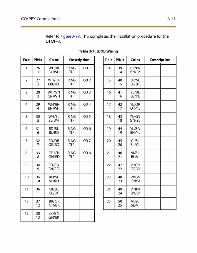
CO/PBX Connections 3-41
Refer to Figure 3-19. This completes the installation procedure for theDTMF-B.
Table 3-7: LCOB Wiring
Pair PIN # Color Description Pair PIN # Color Description
1 261
WH/BLBL/WH
RINGTIP
CO 1 14 3914
BK/BNBN/BK
2 272
WH/OROR/WH
RINGTIP
CO 2 15 4015
BK/SLSL/BK
3 283
WH/GNGN/WH
RINGTIP
CO 3 16 4116
YL/BLBL/YL
4 294
WH/BNBN/WH
RINGTIP
CO 4 17 4217
YL/OROR/YL
5 305
WH/SLSL/WH
RINGTIP
CO 5 18 4318
YL/GNGN/YL
6 316
RD/BLBL/RD
RINGTIP
CO 6 19 4419
YL/BNBN/YL
7 327
RD/OROR/RD
RINGTIP
CO 7 20 4520
YL/SLSL/YL
8 338
RD/GNGN/RD
RINGTIP
CO 8 21 4621
VI/BLBL/VI
9 349
RD/BNBN/RD
22 4722
VI/OROR/VI
10 3510
RD/SLSL/RD
23 4823
VI/GNGN/VI
11 3611
BK/BLBL/BK
24 4924
VI/BNBN/VI
12 3712
BK/OROR/BK
25 5025
VI/SLSL/VI
13 3813
BK/GNGN/BK

3-42 CO/PBX Connections
Figure 3-17: LCOB w/DTMF-B Installation

CO/PBX Connections 3-43
Ground Start CO Trunk Board (GCOB)The GCOB board provides the interface to eight Ground Start CO, FX, orWATS trunks.
Each trunk circuit contains a hybrid, 2-wire interface circuit andcontrol circuitry.
The operation for Pulse Dialing or DTMF signaling can be done on aper circuit basis.
Each circuit has an LED indicator that gives trunk status.
Each trunk circuit can be disabled as well as the card.
A Normal/Service switch located toward the top of the card allowsthe card to be inserted or removed from the system while underpower.
The CO lines are connected via a 50-pin male amphenol connectorlocated on the front edge of the card.
The card can accept a DTMF-B unit in a daughter board typearrangement.
The card ejector tabs are color coded white.
Installing the DTMF-B Module1. Unpack the DTMF-B Module from its anti-static conductive bag in the
packing box.
2. Locate the K1 and K2 connectors on the DTMF-B module.
3. Locate the K2 and K3 connectors on the GCOB (outlined).
4. Position the DTMF-B module so that the K2 and K1 connectors matchup with the K3 and K2 connectors on the GCOB respectively.
5. Push the DTMF-B module onto these connectors making sure it isseated properly.
Refer to Figure 3-18. This completes the installation procedure for theDTMF-B.

3-44 CO/PBX Connections
Table 3-8: GCOB Wiring
Pair PIN # Color Description Pair PIN # Color Description
1 261
WH/BLBL/WH
RINGTIP
CO 1 14 3914
BK/BNBN/BK
2 272
WH/OROR/WH
RINGTIP
CO 2 15 4015
BK/SLSL/BK
3 283
WH/GNGN/WH
RINGTIP
CO 3 16 4116
YL/BLBL/YL
4 294
WH/BNBN/WH
RINGTIP
CO 4 17 4217
YL/OROR/YL
5 305
WH/SLSL/WH
RINGTIP
CO 5 18 4318
YL/GNGN/YL
6 316
RD/BLBL/RD
RINGTIP
CO 6 19 4419
YL/BNBN/YL
7 327
RD/OROR/RD
RINGTIP
CO 7 20 4520
YL/SLSL/YL
8 338
RD/GNGN/RD
RINGTIP
CO 8 21 4621
VI/BLBL/VI
9 349
RD/BNBN/RD
22 4722
VI/OROR/VI
10 3510
RD/SLSL/RD
23 4823
VI/GNGN/VI
11 3611
BK/BLBL/BK
24 4924
VI/BNBN/VI
12 3712
BK/OROR/BK
25 5025
VI/SLSL/VI
13 3813
BK/GNGN/BK

CO/PBX Connections 3-45
Figure 3-18: GCOB w/DTMF-B Installation

3-46 CO/PBX Connections
DID Trunk Board (DIDB)The DIDB board provides the interface to eight (8) Direct Inward Dialing(DID) trunks.
Each of the trunk circuits contain a hybrid, 2- wire interface circuit andcontrol circuitry.
The operation for dial-repeating address or DTMF signaling can beimmediate, wink, or delay-start supervision.
Each circuit has an LED indicator that gives trunk status. Each circuitcan be disabled as well as the card.
The CO Lines are connected via a 50-pin male amphenol connectorlocated on the card front edge.
A Normal/Service switch located toward the top of the card allowsthe card to be inserted or removed from the system while underpower.
The card can accept a DTMF4-B unit as a daughter board typearrangement. This unit has 4 DTMF Receivers installed on it. Thisboard can be installed on the LCOB, GCOB, and DIDB boards. Thisboard mounts as a daughter board type arrangement.
Installing the DTMF-B Module1. Unpack the DTMF-B Module from its anti-static conductive bag in the
packing box.
2. Locate the K1 and K2 connectors on the DTMF-B module.
3. Locate the K2 and K3 connectors on the DIDB (outlined).
4. Position the DTMF-B module so that the K2 and K1 connectors matchup with the K3 and K2 connectors on the DIDB respectively.
5. Push the DTMF-B module onto these connectors making sure it isseated properly.
Refer to Figure 3-19. This completes the installation procedure for theDTMF-B.

CO/PBX Connections 3-47
Table 3-9: DIDB Wiring
Pair PIN # Color Description Pair PIN # Color Description
1 261
WH/BLBL/WH
RINGTIP
CO 1 14 3914
BK/BNBN/BK
2 272
WH/OROR/WH
RINGTIP
CO 2 15 4015
BK/SLSL/BK
3 283
WH/GNGN/WH
RINGTIP
CO 3 16 4116
YL/BLBL/YL
4 294
WH/BNBN/WH
RINGTIP
CO 4 17 4217
YL/OROR/YL
5 305
WH/SLSL/WH
RINGTIP
CO 5 18 4318
YL/GNGN/YL
6 316
RD/BLBL/RD
RINGTIP
CO 6 19 4419
YL/BNBN/YL
7 327
RD/OROR/RD
RINGTIP
CO 7 20 4520
YL/SLSL/YL
8 338
RD/GNGN/RD
RINGTIP
CO 8 21 4621
VI/BLBL/VI
9 349
RD/BNBN/RD
22 4722
VI/OROR/VI
10 3510
RD/SLSL/RD
23 4823
VI/GNGN/VI
11 3611
BK/BLBL/BK
24 4924
VI/BNBN/VI
12 3712
BK/OROR/BK
25 5025
VI/SLSL/VI
13 3813
BK/GNGN/BK

3-48 CO/PBX Connections
Figure 3-19: DIDB w/DTMF-B Installation

CO/PBX Connections 3-49
T-1 Interface Board (T1IB)The T1IB board allows the network connection to a T-1 (1.544Mbps, 24Voice Channel) digital interface.
The T1IB contains T-1 interface circuit, control circuitry, and synchronousclock control circuits. DTMF tone detection units can be installedoptionally on the T1IB. The T1IB has 8 LEDs on the front edge of the PCBwhich indicates errors of T-1 line, in-use status, and synchronous clockenable status.
The T1IB contains 3 switches and 2 connectors. The Normal/Serviceswitch is used during maintenance to place the card in an Out-Of-Service(OOS) mode. The clock selection switch is used for control synchronousclock. The Line Build-Out switch is controlled by distance between theTriad 3 System and a CSU and the Switch #4 is used for loopback control.
The PLLU must be installed on the MPB for the T- 1 card to operateproperly.
Software 2.1G or neweris needed when using any T-1 cardthat contains1.0G Firmware. Without the newer software, the T-1 card will not work.
Table 3-10: T-1 Board LEDs
LED Function
1 IN USE At least one of the 24 circuits is in use.
2 RED T1IB is in RED alarm due to any alarm.
3 H/W TEST Normal call processing is not available.
4 BLUE T1IB has detected RX_BLUE alarm.
5 YELLOW T1IB has detected RX_YELLOW alarm.
6 OOF T1IB is Out of Frame synchronization
7 RCL T1IB receives Carrier Loss (un-plugged from the cable)
8 CLOCK Clock Enable/Disable T-1 Ordering Information

3-50 CO/PBX Connections
The system can be equipped with four (4) T-1 Interface Boards and theT1IB can be installed in card slots 0-8 in the Basic KSU. The Phase LockedLoop Unit (PLLU) must be installed on the MPB when the T1IB is installed.The DTMF4-A board which contains 4 DTMF receivers can be optionallyinstalled on the T1IB.
The clock control cable should be connected by daisy-chain method likeFigure 3-20: T-1 Clock Connect Cable Installation when more than oneT1IB boards are installed. When the clock control cable of the T1IB isconnected by daisy-chain method, the clock selection switch of the firstT1IB must be placed in the Enable position and the other board shouldbe placed in the Disable position. The Line Build-Out switch must beselected by distance between the Triad 3 System and a CSU and theswitch selection as indicated below. If the CSU is located near the KSU, allLBO switches should be ON.
The SW1 switch #4 of the Line Build-Out switch is used for LoopBackcontrol. Its switch is used only for hardware test and must be placed inthe ON position for normal operation.
Table 3-11: T-1 Ordering Information
T-1 Ordering Information
Ringer Equivalent Number 6.0P
Facility Line Interface 04DU9-B
Jack Type RJ48C
Table 3-12: T-1 Switch Positions
DistanceSwitch #
1 2 3 4
0 to 133 feet on on on on
133 to 266 feet off on on on
266 to 399 feet on off on on
399 to 533 feet off off on on
533 to 655 feet on on off on

CO/PBX Connections 3-51
If the T1IB is to be installed in a live system, the Normal/Service switchshould be placed in the Service position. After installing the board, theNormal/Service switch must be placed in the Normal position.
This board supports standard D4 framing format with robbed bitsignaling. The Extended Super Frame (ESF-B8ZS) format is alsosupported.
The board can support TIE, Loop and Ground start signalingemulation per channel.
The board requires an external CSU unit.
The T-1 board can accept two (2) DTMF-A units in a daughter boardtype arrangement. This unit has 4 DTMF Receivers installed on it. Thisboard can be installed on the SLIB, and T1IB boards.
The board has a 15-pin D Sub connector for connection to a CSU unit.
The card ejector tabs are color coded white.
Functionality DescriptionAutomatic Number Identification (ANI) information from the carrier istreated exactly the same as an inbound ICLID (Caller ID) number. Callscan be routed, placed in the unanswered call table, sent out to the CTIModule port on a keyset, and run through the number to nametranslation table. The Triad 3 System provides call progress tones in thesame manner as ICLID.
Dialed Number Identification Service (DNIS) information from thecarrier is treated using DID line rules. DNIS calls are routed based on theDID routing table.
ANI/DNIS is a combined format, where the system waits for the ANI/DNISinformation from the carrier. When it is received, the system routes thecall using ICLID processing.
If this information is not found in the ICLID Route Tables, the DNISinformation is compared to the DID table for a match. The call is thenrouted based on the DID tables.
If a match is not found on either the ANI or DNIS number, the call isrouted based on normal CO line operation (CO Ringing Assignments).

3-52 CO/PBX Connections
The following table summarizes the operation of the system.
Table 3-13: Call Routing Criteria
ANI DNIS Operation
N N Calls routed based on normal CO operation (CO RingAssignments).
N Y Calls routed based on DID tables with DID operation.
Y N Calls routed based on ICLID routing and ICLID operation
Y* Y Calls routed on ICLID first, if no route is found, the DNIS digits arecompared to the DID table.
If no route is found in the DID table the call is routed based on COline Ringing Assignments.
* If both ANI and DNIS calls are routed -- the following table summarizes what is displayed at the phone.
The T-1 card accepts ANI/DNIS informationin aDTMF formatonly. Somecarriers do notprovide ANI or ANI/DNIS in a DTMF format. Consult your local carrier for availableoptions.
Table 3-14: Call Routing Display Format
RouteFound
Type ofDisplay
Format
ICLID ICLID ANI number placed in the 14-character number field, the DNISnumber followed by the name programmed in ICLID translationtable placed in the 24-character name field.
DID ICLID ANI number placed in 14-character number field. DNIS numberfollowed by programmed name from the DID tables in24-character name field.
NONE ICLID ANI number placed in 14-character number field and the DNISnumber is placed in the 24-character name field.

CO/PBX Connections 3-53
T-1 Ordering Information: When ordering a T-1 circuit from a carrier,request either D4 framing and Alternate Mark Inversion (AMI) Line codingusing the superframe (SF) or the Extended Superframe (ESF-B8ZS) format.The following are additional ordering information specifications:
If ordering…ANI/DNISDID/TIE
Loop Start/Ground Start Signaling*
Circuit Information 2 wire 2 wire
Supervisory Signaling TIE Loop or Ground
Address Signaling DTMF DTMF
Start Dial Indicator Wink Start Dial Tone
* ANI/DNISnot available on Loop/Ground start signaling. If Loop Start signaling protocol is ordered, TheCentral Office does not provide Disconnect Supervision. However if TIE signaling protocol is ordered,disconnect supervision is provided. The switching equipment processes DNIS numbers received from the T-1circuit depending on the trunk simulation.

3-54 CO/PBX Connections
Figure 3-20: T-1 Clock Connect Cable Installation (Multiple Cards)
1
SW-3
CTRLCLKOUT
CTRLCLK IN
CON3
T1-2
DN
T1-3 4 5 6 7 8
UP
T-1 Lines from Telco Clock Cable
In the case of a Master system, the clock cabledoes not get connected and SW3 on all T-1Boards is in the down position.Two (2) T-1 Cards maximum in the system.
MULTIPLE CARD ARRANGEMENT

CO/PBX Connections 3-55
Figure 3-21: T-1 Clock Connect Cable Installation (Single Card)
1
SW-3
CON3
T1-2 T1-3 4 5 6 7 8
UP
T-1 Lines from Telco
SINGLE CARD ARRANGEMENT

3-56 CO/PBX Connections
Installing the DTMF-A Modules1. Unpack the DTMF-A Modules from their antistatic conductive bags in
the packing boxes.
2. Locate the CONN5 and CONN6 connectors on the DTMF-A modules.
3. Locate the CON4, CON5, CON8 and CON9connectors on the T1IB(outlined).
4. Position one of the DTMF-A modules so that the CONN5 and CONN6connectors match up with the CON8 and CON9 connectors on theT1IB respectively.
5. Push the DTMF-A module onto these connectors making sure it isseated properly.
6. Position the second DTMF-A module so that the CONN5 and CONN6connectors match up with the CON4 and CON5 connectors on theT1IB respectively.
7. Push the DTMF-A module onto these connectors making sure it isseated properly.
Refer to Figure 3-22. This completes the installation procedure for theDTMF-A Modules.
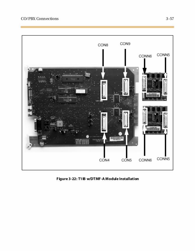
CO/PBX Connections 3-57
Figure 3-22: T1IB w/DTMF-A Module Installation

3-58 CO/PBX Connections
Primary Rate Interface Board (PRIB)The PRIB board allows the network connection to a Primary Rate ISDNinterface. It provides one Primary Rate Interface circuit. Each circuit iscomprised of 23 bearer channels and one data channel (23B+D). Thesystem interprets all B channels as trunks/line appearances. A maximumof six PRIBs can be installed into the system. The PRIB uses 24 time slots.
The PRIB contains an ISDN interface circuit, control circuitry, andsynchronous clock control circuits. DTMF tone detection units can beinstalled optionally on the PRIB. The PRIB accepts two DTMF-A boards.The PRIB has 8 LEDs on the front edge of the PCB which indicates errorsof ISDN line, in-use status, and synchronous clock enable status.
The PLLU must be installed on the MPB for the PRIB card to operateproperly.
Vodavi has successfully integrated its PRI ISDN with the Lucent 5 ESS,Siemens, Strom burg Carlson, and the DMS100 Central Offices. VodaviISDN should work with all Central Office switches, but this has not beenverified. Therefore, som e delays in service m ay be experienced.
Table 3-15: PRIB Board LEDs
LED Function
1 (Green) OFFON
Line IdleLine busy (use)
Line Status
2 (Red) OFFON
NormalRX Carrier Loss
PRI Line Error Status
3 (Red) OFFON
NormalOut of Frame
4 (Red) OFFON
NormalYellow Alarm
5 (Red) OFFON
NormalAIS or Blue Alarm
6 (Red) OFFON
NormalLoop
7 (Red) OFFON
NormalMulti-Frame Establish Alarm
8 (Red) OFFON
Clock DisableClock Enable
Clock Status

CO/PBX Connections 3-59
The PRIB contains 2 switches and 3 connectors. The Normal/Serviceswitch is used during maintenance to place the card in an Out-Of-Service(OOS) mode. The clock selection switch is used for control synchronousclock.
The system can be equipped with six (6) PRI Interface Boards and the PRIBcan be installed in any card slot in the Basic KSU. The Phase Locked LoopUnit (PLLU) must be installed on the MPB when the PRIB is installed. TheDTMF4-A board which contains 4 DTMF receivers can be optionallyinstalled on the PRIB.
If the PRIB is to be installed in a live system, the Normal/Service switchshould be placed in the Service position. After installing the board, theNormal/Service switch must be placed in the Normal position for properoperation.
This board supports Extended Super Frame (ESF) format and B8ZSline coding.
The board can support TIE, Loop and Ground start signalingemulation per channel.
The board requires an external CSU unit.
The PRIB board can accept two (2) DTMF-A units in a daughter boardtype arrangement. This unit has 4 DTMF Receivers installed on it. Thisboard can be installed on the SLIB, and T1IB boards.
The board has a 15-pin D Sub connector for connection to a CSU unit.
The card ejector tabs are color coded white.
Table 3-16: PRI Ordering Information
PRI Ordering Information
Ringer Equivalent Number 6.0P
Facility Line Interface 04DU9-B
Jack Type RJ45
When ordering a PRI circuit from a carrier, request the NI-2 standard.

3-60 CO/PBX Connections
Installation1. Insert the PRIB card(s) into the desired BKSU card slot(s). Up to six
PRIB cards can be installed in a system. Each PRIB provides 23 COLines to the system.
2. If installing a single PRIB, set SW2 to the ON position.
If multiple PRIBs are being installed, set SW2 to the ON position onthe first card and SW2 on all other cards to the OFF position.
The PRIB comes with a clock cable. This cable is used when multiplePRIB and/or digital trunk cards are to be installed in the system. Theclock cable is supplied with each PRIB.
3. Connect the DB15 cable from the PRIB to the CSU.
4. Connect the network cable from the CSU to the network.
5. Refer to ISDN and T1 Clocking for clarification on clocking and cablingwhen combining BRIB, PRIB, and T1 cards in one KSU.
Figure 3-23: PRIB (Primary Rate Interface Board)
The PRIB is offered as a stand-alone card or as a kit which includes thePRIB, CSU, and cables.

CO/PBX Connections 3-61
Functionality DescriptionAutomatic Number Identification (ANI) information from the carrier istreated exactly the same as an inbound ICLID (Caller ID) number. Callscan be routed, placed in the unanswered call table, sent out to the CTIModule port on a keyset, and run through the number to nametranslation table. The Triad 3 System provides call progress tones in thesame manner as ICLID.
Dialed Number Identification Service (DNIS) information from thecarrier is treated using DID line rules. DNIS calls are routed based on theDID routing table.
ANI/DNIS is a combined format, where the system waits for the ANI/DNISinformation from the carrier. When it is received, the system routes thecall using ICLID processing.
If this information is not found in the ICLID Route Tables, the DNISinformation is compared to the DID table for a match. The call is thenrouted based on the DID tables.
If a match is not found on either the ANI or DNIS number, the call isrouted based on normal CO line operation (CO Ringing Assignments).
The following table summarizes the operation of the system.
Table 3-17: Call Routing Criteria
ANI DNIS Operation
N N Calls routed based on normal CO operation (CO Ring Assignments.
N Y Calls routed based on DID tables with DID operation.
Y N Calls routed based on ICLID routing and ICLID operation.
Y* Y Calls routed on ICLID first, if no route is found, the DNIS digits arecompared to the DID table. If no route is found in the DID table thecall is routed based on CO line Ringing Assignments.
*I f both ANI and DNIS calls are routed -- the following tabl e summarizes what i s displayed at the phone.

3-62 CO/PBX Connections
Installing the DTMF-A Modules
1. Unpack the DTMF-A Modules from their antistatic conductive bags inthe packing boxes.
2. Locate the CONN5 and CONN6 connectors on the DTMF-A modules.
3. Locate the CON4, CON5, CON8 and CON9connectors on the PRIB(outlined).
4. Position one of the DTMF-A modules so that the CONN5 and CONN6connectors match up with the CON8 and CON9 connectors on thePRIB respectively.
5. Push the DTMF-A module onto these connectors making sure it isseated properly.
6. Position the second DTMF-A module so that the CONN5 and CONN6connectors match up with the CON4 and CON5 connectors on thePRIB respectively.
7. Push the DTMF-A module onto these connectors making sure it isseated properly.
Refer to Figure 3-24. This completes the installation procedure for theDTMF-A Modules.
Table 3-18: Call Routing Display Format
RouteFound
Type ofDisplay
Format
ICLID ICLID ANI number placed in the 14-character number field,the DNIS number followed by the name programmedin ICLID translation table placed in the 24-charactername field.
DID ICLID ANI number placed in 14-character number field. DNISnumber followed by programmed name from the DIDtables in 24-character name field.
NONE ICLID ANI number placed in 14-character number field andthe DNIS number is placed in the 24-character namefield.

CO/PBX Connections 3-63
Figure 3-24: PRIB w/DTMF-A Module Installation
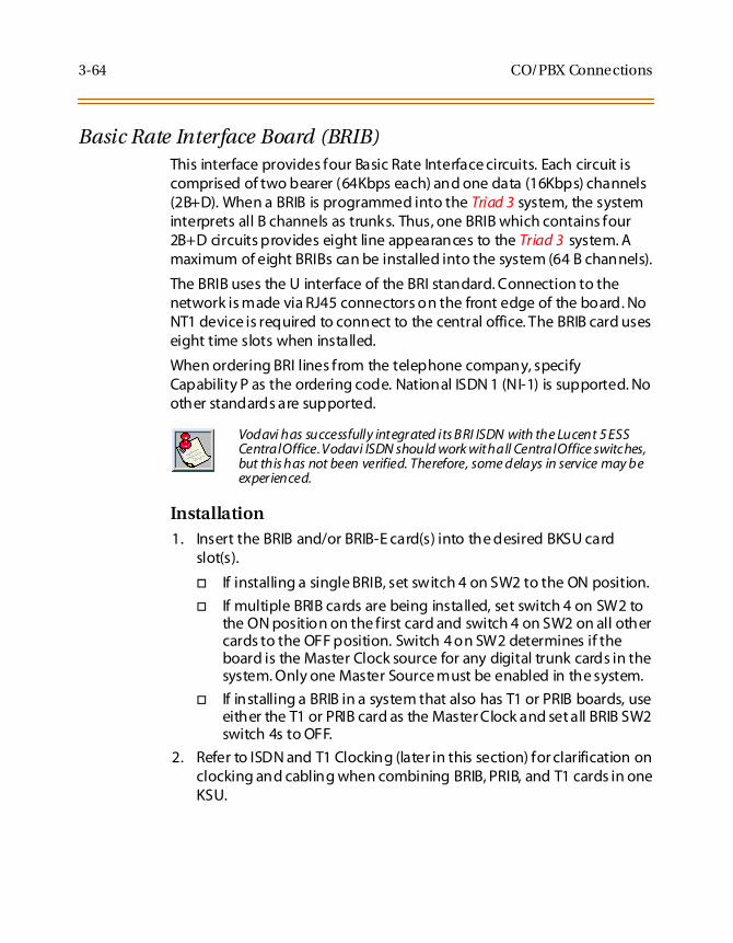
3-64 CO/PBX Connections
Basic Rate Interface Board (BRIB)This interface provides four Basic Rate Interface circuits. Each circuit iscomprised of two bearer (64Kbps each) and one data (16Kbps) channels(2B+D). When a BRIB is programmed into the Triad 3 system, the systeminterprets all B channels as trunks. Thus, one BRIB which contains four2B+D circuits provides eight line appearances to the Triad 3 system. Amaximum of eight BRIBs can be installed into the system (64 B channels).
The BRIB uses the U interface of the BRI standard. Connection to thenetwork is made via RJ45 connectors on the front edge of the board. NoNT1 device is required to connect to the central office. The BRIB card useseight time slots when installed.
When ordering BRI lines from the telephone company, specifyCapability P as the ordering code. National ISDN 1 (NI-1) is supported. Noother standards are supported.
Installation1. Insert the BRIB and/or BRIB-E card(s) into the desired BKSU card
slot(s).
If installing a single BRIB, set switch 4 on SW2 to the ON position.
If multiple BRIB cards are being installed, set switch 4 on SW2 tothe ON position on the first card and switch 4 on SW2 on all othercards to the OFF position. Switch 4 on SW2 determines if theboard is the Master Clock source for any digital trunk cards in thesystem. Only one Master Source must be enabled in the system.
If installing a BRIB in a system that also has T1 or PRIB boards, useeither the T1 or PRIB card as the Master Clock and set all BRIB SW2switch 4s to OFF.
2. Refer to ISDN and T1 Clocking (later in this section) for clarification onclocking and cabling when combining BRIB, PRIB, and T1 cards in oneKSU.
Vodavi has successfully integrated its BRI ISDN with the Lucent 5 ESSCentralOffice.Vodavi ISDN should work withall CentralOffice switches,but this has not been verified. Therefore, some delays in service may beexperienced.

CO/PBX Connections 3-65
Figure 3-25: BRIB (Basis Rate Interface Board)
ON
OF
F
SW2 SWITCHES:
234
1

3-66 CO/PBX Connections
Electronic Key Telephone ServiceElectronic key telephone service (EKTS) is a feature that can be providedon BRI ISDN to simulate standard analog DID lines. This allows severaldifferent numbers to be shared by a single BRI circuit.
Due to the decline in telephony tariffs, there is an increasing demand forBRI ISDN features. A BRI circuit allows two simultaneous calls to behandled, due to its technical specification. BRI circuits have twoB-Channels at 64 kilobytes per second and one D-Channel at 16 kilobytesper second. The Bearer (B) Channels are designed for PCM (voice) and theData (D) Channel is designed to carry information specific to eachincoming and/or outgoing call.
The EKTS feature allows a single ISDN Service Profile Identifier (SPID) orB-Channel to support multiple directory numbers. A SPID is a numberthat telephone company switching equipment uses to trackconfiguration information for each terminal adapter connected to anISDN telephone line. The telephone company should provide SPIDs atthe same time that the ISDN directory numbers are assigned. A directorynumber is another term for a telephone number.
If an application requires EKTS, be aware that BRI ISDN handles a busynumber differently than a DID circuit. When the called number is busy,BRI will issue a busy signal, but a DID circuit will ring another line in thecircuit. The busy signal is provided by the telephone company, thereforethe call is not presented to the Vodavi telephone switch and it is notforwarded to voice mail. For example, a caller dials 480-443-6000 and isconnected to the extension. While the first caller is still connected, asecond caller dials the same number. The second caller will receive a busysignal that is provided by the telephone company.
In a normal BRI application, two numbers are assigned to each BRI circuit,which consists of 2 channels. There can be a maximum of 4 circuitsequipped to handle 8 channels per BRIB. This is a direct number-to-channel relationship without hunting capability. Most circuit providersoffer an optional “hunting” feature capability on BRI circuits. This optionalfeature allows numbers to hunt for idle channels on the BRIB up to amaximum of 8 channels per BRIB, assuming four BRI circuits wereinstalled. In EKTS applications, you can have a maximum of 64 DIDnumbers hunt to one BRIB. Hunting cannot be accomplished betweenBRIBs, nor will the hunting feature allow calls to be routed to a busy DIDnumber.

CO/PBX Connections 3-67
ConditionsBRI EKTS support is available in Vodavi telephone systems with softwareversion 3.0G and higher.
Like DID, EKTS can be programmed to route calls using up to 7 digits. Bydefault, only the last three digits are analyzed for routing.
EKTS does not require a line appearance on a specific telephone becausethe BRI terminates directly into the KSU.
Vodavi supports Basic EKTS. The EKTS caching option is not supported byVodavi. Caching is normally used when an ISDN telephone instrument isused on the customer premise.
Basic Rate Interface Expansion Board (BRIB-E)This card installs as a daughter-board on the BRIB and provides anadditional four Basic Rate Interface circuits. One BRIB and BRIB-Eassembly provides 16 line appearances to the Triad 3system. A maximumof four BRIB/BRIB-E assemblies can be installed into the system.
The BRIB-E uses the U interface of the BRI standard. Connection to thenetwork is made via RJ45 connectors on the front edge of the board. TheBRIB-E card uses eight time slots when installed.

3-68 CO/PBX Connections
ISDN and T1 ClockingWhen combining BRIB, PRIB, and T1 cards in one KSU, specific settingsand cabling are important for proper clocking. The Phase Lock Loop Unit(PLLU) synchronizes the clocking from the Central Office to the clockingof the KSU. Popping, crackling, dropped calls, and one-way transmissionare usually attributed to the clocking not being synchronized correctly.
Examples - Settings and CablingThe following examples clarify the clocking and cabling for these cards:
(1) T1IB and (1)PRIB
If both cards in a phone switch are connected to a telephone companyclock (not point-to-point T1), put the T1 clock switch in the enableposition (UP) to allow it to receive clocking from the telephone companydirectly, and do not install the clock cable. Set the PRIB clock switch in thedisable position (OFF), which allows the PRIB to synchronize its timing offof the backplane (from the T1 clocking). If the T1 is a point-to-point T1,set the PRIB in the enable position (ON), the T1 in the disable position(OFF), and do not install the clock cable.
When the switch is in the “up” position, it shouldbe considered “ON”. Whenthe switch is in the “down” position, it should be considered “OFF”.
The cable connection follows the same logic - “up” is clock outside (ON) and“down” is clock inside(OFF).ON means thatclocking is coming from outsidethe KSU and OFF means that clocking is coming from inside the KSU.
T1IB PRIB
SW3 On SW2 Off

CO/PBX Connections 3-69
(1) PRIB and (1) BRIB
Install with the cable and set both PRIB and BRIB switches to the enableposition (ON).
(1) T1IB and (1) BRIB
If both cards in a phone switch are connected to a telephone companyclock (not point-to-point T1), put the T1 clock switch in the enableposition (ON) to allow it to receive clocking from the telephone companydirectly. Do not install the clock cable.
Set the BRIB clock switch in the disable position (OFF), which allows theBRIB to synchronize its timing off of the backplane (from the T1 clocking).
If the T1 is a point-to-point T1, set the BRIB to the enable position (ON),the T1 in the disable position (OFF), and do not install the clock table.
PRIB BRIB
Sw2 On Switch 4, SW2 On
T1IB BRIB
SW3 On Switch 4, SW2 Off

3-70 CO/PBX Connections
(2) PRIBs and (3) T1IBs
The clock cable should be connected to the OUT position on theconnector on the PRIB1. The clock cable should be connected to the INposition on PRIB2. SW2 of the PRIB1 and PRIB2 should be placed in theON position. The three T1IBs are not connected with the clock controlcable and SW3 on these boards should be in the OFF position.
(3) T1IBs and (2) PRIBs
The clock cable should be connected to the OUT position on the cableconnector on the T1IB and connected to the IN position on the connectoron the T1IB2. The clock cable should be connected to the OUT positionon T1IB2 and connected to the IN position on the T1IB3. SW3 of T1IB1should be placed in the ON position, with SW3 on T1IB2 and T1IB3 beingOFF. The two PRIBs are not connected with clock control cables, and SW2on the PRIBs should be in the OFF position.
PRIB1 PRIB2 T1IB1 T1IB2 T1IB3
SW2 On SW2 On SW3 Off SW3 Off SW3 Off
T1IB1 T1IB2 T1IB3 PRIB1 PRIB2
SW3 On SW3 Off SW3 Off SW2 Off SW2 Off

CO/PBX Connections 3-71
(3) PRIBS and (2) BRIBs
The clock cable should be connected from the OUT position of the PRIB1to the IN connectors of all the cards and all clock switches should be inthe ON position.
(3) T1IBs and (2) BRIBs
The clock OUT cable from T1IB1 should be connected to the clock INcable of the T1IB2 and the clock OUT cable from T1IB2 should beconnected to the clock IN cable of T1IB3. SW3 of T1IB1 should be in theON position, and SW3 of T1IB2 and T1IB3 should be in the OFF position.The two BRIBs are not connected with clock control cables and SW2 ofthe BRIB cards are placed in the OFF position.
PRIB1 PRIB2 PRIB3 BRIB1 BRIB2
SW2 On SW2 On SW2 On Switch 4, SW2 On Switch 4, SW2 On
T1IB1 T1IB2 T1IB3 BRIB1 BRIB2
SW3 On SW3 Off SW3 Off Switch 4, SW2 Off Switch 4, SW2 Off

3-72 Station Connections
Station Connections
The peripheral boards provide the interface from system PCM ports tostation.
Electronic Telephone Interface Board (ETIB)This board provides the interface to twelve (12) electronic telephones orDSS/DTS terminals. The card has one LED indicator for off-hook/in usestatus. The ETIB can be installed or removed under system power. Thecard extractors are color coded green.
There is one 50-pin female amphenol connectors labeled Conn2 locatedon the front of the card. This allows the system to be cabled to the maindistribution frame (MDF). 25-pair telephone cabling must be preparedwith mating connectors to extend the inter-face circuits to the MDF. Thecables should be routed through the cable clamps at the bottom of theKSU to the MDF. These cables are then terminated on industry standard66M1-50 type punchdown connector blocks. It is recommended that66M1-50 split blocks with bridging clips be used to simplifytroubleshooting and to quickly isolate faults.
Basic Key Telephones are not supported atthis time.
Only DTIB type stations can be used for Database programming.

Station Connections 3-73
Table 3-19: ETIB Wiring
Pair PIN # Color Description Pair PIN # Color Description
1 261
WH/BLBL/WH
RINGTIP
CKT1 15 4015
BK/SLSL/BK
RINGTIP
CKT8
2 272
WH/OROR/WH
DATA-RDATA-T
16 4116
YL/BLBL/YL
DATA-RDATA-T
3 283
WH/GNGN/WH
RINGTIP
CKT2 17 4217
YL/OROR/YL
RINGTIP
CKT9
4 294
WH/BNBN/WH
DATA-RDATA-T
18 4318
YL/GNGN/YL
DATA-RDATA-T
5 305
WH/SLSL/WH
RINGTIP
CKT3 19 4419
YL/BNBN/YL
RINGTIP
CKT10
6 316
RD/BLBL/RD
DATA-RDATA-T
20 4520
YL/SLSL/YL
DATA-RDATA-T
7 327
RD/OROR/RD
RINGTIP
CKT4 21 4621
VI/BLBL/VI
RINGTIP
CKT11
8 338
RD/GNGN/RD
DATA-RDATA-T
22 4722
VI/OROR/VI
DATA-RDATA-T
9 349
RD/BNBN/RD
RINGTIP
CKT5 23 4823
VI/GNGN/VI
RINGTIP
CKT12
10 3510
RD/SLSL/RD
DATA-RDATA-T
24 4924
VI/BNBN/VI
DATA-RDATA-T
11 3611
BK/BLBL/BK
RINGTIP
CKT6 25 5025
VI/SLSL/VI
12 3712
BK/OROR/BK
DATA-RDATA-T
13 3813
BK/GNGN/BK
RINGTIP
CKT7
14 3914
BK/BNBN/BK
DATA-RDATA-T

3-74 Station Connections
Figure 3-26: Electronic Telephone Interface Board (ETIB)

Station Connections 3-75
Single Line Interface Board (SLIB)This board provides the interface to twelve (12) 2500-type telephones.The SLIB signals interface with mechanical 90V ringers and lights 90Vmessage waiting lamps on 2500 sets as desired. The SLIB board has oneLED indicator for status. A Normal/Service switch located toward the topof the card allows the card to be inserted or removed from the systemwhile under power and also can be used to disable all station circuits onthe card.
The station connections are via one (1) 50-pin female (amphenol type)connector located on the front edge of the card.
The board can support a MSG12 board and a DTMF4-A board in adaughter board type arrangement.
The Message Wait Lamp Relay Control (MSG12) provides Message WaitLamp Relay Control for message lamp single line telephones. The MSG12board mounts on the SLIB board as a daughter board type arrangement.
Installing the MSG12 Board1. Unpack the MSG12 Module from its anti-static conductive bag in the
packing box.
2. Locate the CONN5 and CONN6 connectors on the MSG12 module.
3. Locate the CONN3, and CONN4 connectors on the SLIB (outlined).
4. Position the MSG12 module so that the CONN3 and CONN4connectors match up with the CONN3 and CONN4 connectors on theSLIB respectively.
5. Push the MSG12 module onto these connectors making sure it isseated properly.
Refer to Figure 3-27. This completes the installation procedure for theMSG12 Module.

3-76 Station Connections
Adjusting Modem SettingsWhen using modems connected to single line telephone ports on theTriad 1/2/3, the gain settings on the SLT port when using T1 as access tothe CO should be set to 0 dB (maximizes the modem speed).
CO to SLT Call via a T1 TIE Trunk:1. Access the specific trunk type above.
2. Hookflash and dial 638 8 on the keypad.
3. Hang up.
CO to SLT Call via a T1 Trunk:1. Access the specific trunk type above.
2. Hookflash and dial 638 6 on the keypad.
3. Hang up.
SLT to SLT Call:1. Place an intercom call from 1 SLT to another.
2. Hookflash and dial 638 5 on the keypad.
3. Hang up.
No adjustment is needed if access to the CO is accomplished bystandard loop/ground start trunk circuits. These trunk types are set to0 dB by default.
In all cases the maximum modem speed is not as much as if themodem were connected directly to the CO line. The system degradesthe connection to the next lower baud rate that the modemsupports.
Example: If the modem can achieve 28800 on a direct CO line, themaximum speed on an SLT port would be 26400.
Testing proves that a baud rate of 33600 can be achieved with SLT-T1lines. Typical connection speeds with SLT-T1 are 22700-33600. Typicalconnection speeds with SLT-Loop/Ground Start are 17400-23800.
All results were obtained using a 56K U.S. Robotics Sportstermodem.

Station Connections 3-77
Table 3-20: SLIB Wiring
Pair PIN # Color Description Pair PIN # Color Description
1 261
WH/BLBL/WH
RINGTIP
CKT1 14 3914
BK/BNBN/BK
2 272
WH/OROR/WH
RINGTIP
CKT2 15 4015
BK/SLSL/BK
3 283
WH/GNGN/WH
RINGTIP
CKT3 16 4116
YL/BLBL/YL
4 294
WH/BNBN/WH
RINGTIP
CKT4 17 4217
YL/OROR/YL
5 305
WH/SLSL/WH
RINGTIP
CKT5 18 4318
YL/GNGN/YL
6 316
RD/BLBL/RD
RINGTIP
CKT6 19 4419
YL/BNBN/YL
7 327
RD/OROR/RD
RINGTIP
CKT7 20 4520
YL/SLSL/YL
8 338
RD/GNGN/RD
RINGTIP
CKT8 21 4621
VI/BLBL/VI
9 349
RD/BNBN/RD
RINGTIP
CKT9 22 4722
VI/OROR/VI
10 3510
RD/SLSL/RD
RINGTIP
CKT10 23 4823
VI/GNGN/VI
11 3611
BK/BLBL/BK
RINGTIP
CKT11 24 4924
VI/BNBN/VI
12 3712
BK/OROR/BK
RINGTIP
CKT12 25 5025
VI/SLSL/VI
13 3813
BK/GNGN/BK

3-78 Station Connections
Installing the DTMF-A UnitThe DTMF-A unit has 4 DTMF receivers installed on it. This board can beinstalled on the SLIB and T1IB boards. The DTMF-A mounts on the SLIBboard as a daughter board type arrangement.
1. Unpack the DTMF-A Module from its anti-static conductive bag in thepacking box.
2. Locate the CONN5 and CONN6 connectors on the DTMF-A module.
3. Locate the CONN5, and CONN6 connectors on the SLIB (outlined).
4. Position the DTMF-A module so that the CONN5 and CONN6connectors match up with the CONN5 and CONN6 connectors on theSLIB respectively.
5. Push the DTMF-A module onto these connectors making sure it isseated properly.
Refer to Figure 3-27. This completes the installation procedure for theDTMF-A Module.

Station Connections 3-79
Figure 3-27: SLIB w/DTMF-A and MSG12 Installation

3-80 Station Connections
Digital Telephone Interface Board (DTIB)This board provides the interface to twelve (12) digital telephones. Thecard has two LEDs (one for the DTIB board, the other for the DTIBE (DT24)board) to indicate off-hook/in use status. The DTIB can be installed orremoved under system power. The card extractors are color coded green.
There is one 50-pin female amphenol connectors labeled CONN3 locatedon the front of the card. This allows the system to be cabled to the maindistribution frame (MDF). 25-pair telephone cabling must be preparedwith mating connectors to extend the inter-face circuits to the MDF. Thecables should be routed through the cable clamps at the bottom of theKSU to the MDF. These cables are then terminated on industry standard66M1-50 type punchdown connector blocks. It is recommended that66M1-50 split blocks with bridging clips be used to simplifytroubleshooting and to quickly isolate faults.
The Digital Telephone Interface Board Expansion (DTIBE) (DT24) utilizesthe other LED on the DTIB board to indicate off-hook/in use status. ThisPCB is installed onto a DTIB board in a daughter board type arrangementto provide an additional twelve (12) digital phones.
A compatibility issue exists between certain DTIB and DTIB-E boards,which could result in noise on stations connected to particular Issue 2DTIB-E boards.
The boards affected can be identified by the Issue level, which issilkscreened on the boards. VTI has released Issue 1 DTIB and Issue 1DTIB-E boards, as well as Issue 2 DTIB and Issue 2 DTIB-E boards.
The compatibility issue may surface when an Issue 2 DTIB-E is installed onan Issue 1 DTIB. Configure DTIB/DTIB-E cards according to the table toavoid this compatibility issue.
Issue 1 DTIB-E Issue 2 DTIB-E
Issue 1 DTIB Compatible Not Compatible
Issue 2 DTIB Compatible Compatible

Station Connections 3-81
Installing the DTIB-E Expansion Module1. Unpack the DTIB-E Expansion Module from its antistatic conductive
bag in the packing box.
2. Locate the CONN1 and CONN2 connectors on the DTIB-E module.
3. Locate the CONN1 and CONN2 connectors on the DTIB (outlined).
4. Position the DTIB-E module so that the CONN1 and CONN2connectors match up with the CONN1 and CONN2 connectors on theDTIB respectively.
5. Push the DTIB-E module onto these connectors making sure it isseated properly.
Refer to Figure 3-28. This completes the installation procedure for theDTIB-E Module.
No DTIB-E cards can be installed in the upper cabinets. These arecabinets #1 and #3.

3-82 Station Connections
Table 3-21: DTIB Wiring
Pair PIN # Color Description Pair PIN # Color Description
1 261
WH/BLBL/WH
DATA-R 1DATA-T 1
DTI
B1
2S
tati
on
Por
ts
13 3813
BK/GNGN/BK
DATA-R 13DATA-T 13
DTI
B2
4S
tati
on
Por
ts
2 272
WH/OROR/WH
DATA-R 2DATA-T 2
14 3914
BK/BNBN/BK
DATA-R 14DATA-T 14
3 283
WH/GNGN/WH
DATA-R 3DATA-T 3
15 4015
BK/SLSL/BK
DATA-R 15DATA-T 15
4 294
WH/BNBN/WH
DATA-R 4DATA-T 4
16 4116
YL/BLBL/YL
DATA-R 16DATA-T 16
5 305
WH/SLSL/WH
DATA-R 5DATA-T 5
17 4217
YL/OROR/YL
DATA-R 17DATA-T 17
6 316
RD/BLBL/RD
DATA-R 6DATA-T 6
18 4318
YL/GNGN/YL
DATA-R 18DATA-T 18
7 327
RD/OROR/RD
DATA-R 7DATA-T 7
19 4419
YL/BNBN/YL
DATA-R 19DATA-T 19
8 338
RD/GNGN/RD
DATA-R 8DATA-T 8
20 4520
YL/SLSL/YL
DATA-R 20DATA-T 20
9 349
RD/BNBN/RD
DATA-R 9DATA-T 9
21 4621
VI/BLBL/VI
DATA-R 21DATA-T 21
10 3510
RD/SLSL/RD
DATA-R 10DATA-T 10
22 4722
VI/OROR/VI
DATA-R 22DATA-T 22
11 3611
BK/BLBL/BK
DATA-R 11DATA-T 11
23 4823
VI/GNGN/VI
DATA-R 23DATA-T 23
12 3712
BK/OROR/BK
DATA-R 12DATA-T 12
24 4924
VI/BNBN/VI
DATA-R 24DATA-T 24
25 5025
VI/SLSL/VI

Station Connections 3-83
Figure 3-28: DTIB w/DTIB-E Installation

3-84 Station Wiring
Station Wiring
Station interface boards (DTIB, ETIB, SLIB) includes a 25 pair connector forstation wiring to the ports on the board. The following provides detailson the interconnection of each type of station interface board and thestation jack.
Digital Keyset & Terminal WiringWiring from the DTIB to station jack requires one pair of wire. Digitizedvoice, signaling, and power are sent over this pair. Figure 3-29 givesdetails on connections of station jacks to the system and Table 3-21 givesthe configuration of the 25-pair station connector arrangement andpunchdown type block.
Figure 3-29: Digital Station Jack Wiring

Station Wiring 3-85
Electronic Keyset and Terminal WiringWiring from the ETIB to station jack requires two pairs of wire. The firstpair provides the audio or voice path, the second is for signaling or datapath. The DATA pair is polarity sensitive, reversal does not harm thekeyset or system, but the port does not function properly when reversed.
Power is delivered by applying DC voltage to the center tap of thecoupling transformers of each of the 2 pairs. Figure 3-26 gives details onconnections of station jacks to the system and Table 3-19gives theconfiguration of the 25-pair station connector arrangement andpunchdown type block.
Figure 3-30: Electronic Station Jack Wiring
Only the first pair (Red, Green on jack) should be connected back totheKSU. No other pairs should be connected back to the KSU.

3-86 Station Wiring
Single Line Telephone WiringThe SLIB is wired to SLT devices with a single pair of wire which providesbattery feed, voice and signaling to and from the SLT. Typical wiring tothe SLT jack is shown in Figure 3-31 and Table 3-20gives the configurationof the 25-pair station connector arrangement when connected to apunchdown type block.
Figure 3-31: Single Line Telephone Wiring

Station Wiring 3-87
Power Failure Transfer WiringThe PFTU is wired from the 25-pair connector to the MDF, crossconnected to the CO Line inputs from the telephone company, to the COLine inputs of the system, and to Power Failure SLTs. The basicconnections are shown in Figure 3-32 and the 25- pair connectorconfiguration is given in Table 3-6. Note that the SLT may also beconnected to a system SLIB as shown.
Figure 3-32: PFTU Wiring

3-88 Wall Mounting the Electronic Telephone
Wall Mounting the Electronic Telephone
All connections to the Electronic Key Telephone are fully modular. To wallmount the Electronic Key Telephone, it is necessary to have one WallMount Kit and one standard-type jack assembly designed for normal wallhanging applications.
1. Unplug the line cord from the phone. This line cord is not be requiredand should be retained as a maintenance replacement item.
2. Lift the plastic number retainer upward and expose the screwunderneath. Remove the screw and the handset tab. Replace it withthe handset tab from the Wall Mount Kit.
3. Be careful to position the tab so that the protrusion faces thehookswitch. This allows the handset to remain secure when thetelephone is on the wall. Replace the screw and snap the numberretainer into place.
4. Substitute the short modular cord from the Wall Mount Assemblyinto the modular connector vacated by the line cord.
5. Align the wall mount baseplate with holes on the bottom of thetelephone. Snap in place.
6. Now match the two key hole slots on the baseplate with the lugs onthe 630-A type jack. Align the modular connector and slide telephoneinto place. (Refer toFigure 3-36.)

Wall Mounting the Digital Telephone 3-89
Wall Mounting the Digital Telephone
To wall mount the Digital Key Telephone, it is necessary to use the WallMount bracket and one standard-type jack assembly designed for normalwall hanging applications. Refer to Figure 3-36 and Figure 3-37.
1. Remove the handset from the cradle and locate the plastic retainer inthe bottom of the hook-switch well area. Push the plastic retainerslowly upward until it is free. Locate the tab on the plastic retainerand make sure the tab is toward you, then place it back into its holder.Slide the plastic retainer all the way down into its channel. Part of theretainer remains above its holder to hold the handset secure for thewall mount configuration.
2. Turn the telephone over and unplug the line cord. If the line cord isnot plugged into the wall jack assembly, re-route the line cord thruthe access channel on the top of the telephone. If the line cord isplugged into the wall jack assembly, run the line cord through thehole provided and plug into the connector on the back of thetelephone.
3. Line up the hooks on the top and bottom of the wall mount bracketso they can engage with the slots cut into the bottom of thetelephone base. Insert the bottom hooks first. Slide the mountingbracket slowly downwards until the top tabs slide into the top slotsand snap in place.
4. Match the two key hole slots on the base plate with the lugs on the630-A type jack. Align the modular connector and slide the telephoneinto place.
5. Place the handset onto the retainer. The telephone is now ready foruse. Refer to Figure 3-37 for location of mounting information.

3-90 Headset Installation
Headset Installation
The Electronic/Digital Key Telephones have been designed to operatewith industry standard electronic mic compatible modular headsetadapters and operator headsets.
To modify an Electronic/Digital Key Telephone to support an externalheadset:
1. Plug the headset adapter cord into the vacant handset jack on theKey Telephone base.
2. Plug the telephone handset cord into the headset adapter box whereindicated by the headset manufacturer's instructions.
The Headset Operation must be enabled (refer to Station Programming).The station then has the capability to enable or disable headset mode bydialing a code. When Headset mode is active at the station, the ON/OFFbutton then controls the on-hook or off-hook status. Also, features suchas On-Hook Dialing and Handsfree Speakerphone operation becomeinoperable.
Caller ID Interface Unit Installation
The Caller Identification Interface Unit receives the data from thetelephone company and sends the data, in ASCII RS-232C format to aprinter, telephone, computer or DTE (Data Terminal Equipment) device.
Selecting the Cable1. Select the RS-232 cable (P/N 9081-10) for the Triad 3 MPB or SIU.
2. Connect one end of the cable on the desired KSU I/O port (1, 3, or 4).
3. Connect the other end to the OUT port on the Caller ID unit.

Caller ID Interface Unit Installation 3-91
Figure 3-33: Caller ID Cable Connections
Figure 3-34: Caller ID Cable Connections - Triad 3 SIU
Triad 3 MPB
KSU 9-PinFemale Connec tion
1440/1480-009-Pin Male
1 1
2 2
3 3
4 4
KSU 5 5 Caller ID Box
6 6
7 7
8 8
9 9
Triad 3SIU
KSU SIURJ48 Connec tion
1440/1480-009-Pin Male
1 1
2 2
3 3
4 4
KSU 5 5 Caller ID Box
6 6
7 7
8 8
9 9
1480-00 Switch SettingsONOFF
1440-00 Switch SettingsONOFF

3-92 Caller ID Interface Unit Installation
Programming the KSU
I/O Ports1. To verify the programming for the I/O ports, press **3226, Flash 15.
2. Select the desired I/O port, Button 1, 3, 4 (MPB, SIU1, SIU2).
3. Dial [5] on the dialpad and press HOLD.
CO Lines1. To verify the programming for the CO Lines, press **3226, Flash 40.
2. Enter CO line Range for the Caller ID Unit and press HOLD.
3. Press Button 21 (Page C).
4. Press Button 2, Ring Delay Timer.
5. Enter 04 (minimum). Press HOLD.
6. Reset the system and the CTI box.
Figure 3-35: CTI System Configuration
CO LINES
ICLIDInterface
Unit
ICLIDInterface
Unit
RS232
STARPLUSKSU
RS232
LANSERVER
CTIModule
CTIModule
CTIModule
LAN
LAN
LAN
LAN

Caller ID Interface Unit Installation 3-93
Figure 3-36: Electronic Key Telephone Wall Mounting

3-94 Caller ID Interface Unit Installation
Figure 3-37: Digital Key Telephone Wall Mounting

Caller ID Interface Unit Installation 3-95
Figure 3-38: SMDR Printout
The SMDR feature provides detailed records of al l outgoing and/or incoming, long distance only or allcalls. The SMDR Quali fication Timer determines the leng th of time that is needed to determine a validSMDR cal l for reporting purposes. By default, this timer is set to 30 seconds and is variable from 00 to 60seconds in 1 sec. increments. This feature is enabled or disabled in system programming. By default,SMDR is not enabled and is set to record long distance calls only. A printout format of 80 charactersmaximum or 30 character maximum may be selected in system programming. The standard format is 80characters on a single line. A 30 character format generates 3 l ines per message. If the SMDR feature isenabled, the system starts collecting information about the call as soon as it starts and terminates whenthe cal l ends. I f the call was longer then 30 seconds, the following information is printed:
30 charac ter format selected:
1 2 3123456789012345678901234567890AAAA BBB HH:MM:SS HH:MM MM/DD/YY(CR)(LF)HCCCCCCCCCCCCCCCCCCCCCCCCCCC<R>GGGGGGGGGGGG
STA CO TOTAL START DATE1116 008 00:02:00 14:13 08/28/00(CR)(LF)0123456789012345678901234(CR)(LF)123456789012(CR)(LF)
80 charac ter format selected:
1 2 3 4 5 6 7 812345678901234567890123456789012345678901234567890123456789012345678901234567890AAAA BBB HH:MM:SS HH:MM MM/DD/YY HCCCCCCCCCCCCCCCCCCCCCCCC GGGGGGGGGGGG (CR)(LF)
STA CO TOTAL START DATE DIALED ACCOUNT CODE<_><_>COST1116 008 00:02:00 14:13 08/28/00 O123456789012345678901234 123456789012(CR)(LF)
80 charac ter format with Call Cost Display feature enabled:
1 2 3 4 5 6 7 812345678901234567890123456789012345678901234567890123456789012345678901234567890AAAA BBB HH:MM:SS HH:MM MM/DD/YY HCCCCCCCCCCCCCCCCCCCCCCCC GGGGGGGGGGGG (CR)(LF)
STA CO TOTAL START DATE DIALED ACCOUNT CODE<~><~>COST1116 008 00:02:00 14:13 08/28/00 O123456789012345678901234 123456789012<_>000.00(CR)(LF)
80 charac ter format for DISA Calls:
1 2 3 4 5 6 7 812345678901234567890123456789012345678901234567890123456789012345678901234567890AAAA BBB HH:MM:SS HH:MM MM/DD/YY HCCCCCCCCCCCCCCCCCCCCCCC GGGGGGGGGGGG (CR)(LF)
STA CO TOTAL START DATE DIALED ACCOUNT CODE<~><~>COST1116 001 00:02:00 14:13 08/28/00 I 123456789012<_>000.00(CR)(LF)001 004 00:04:54 14:15 08/28/00 I0123456789012345678901234 - continued on next page -

3-96 Caller ID Interface Unit Installation
ICLID 30 character format selected:
1 2 3123456789012345678901234567890STA CO TOTAL START DATE1000 001 00:00:19 09:32 08/28/00(CR)(LF)O 480-443-6000(CR)(LF)123456789012 **(CR)(LF)
ICLID 80 character format selected:
1 2 3 4 5 6 7 812345678901234567890123456789012345678901234567890123456789012345678901234567890STA CO TOTAL START DATE DIALED ACCOUNT CODE<_><_>COST1000 001 00:00:36 04:37 08/28/00 I1-480-443-6000 **(CR)(LF)
**VODAVI (CR)(LF)01 00:00:00 04:38 08/28/00 U1-480-443-6000 **
**VODAVI (CR)(LF)
- AAAA = Station originator or Trunk on DISA and Off-Net (CO Line) calls.
- BBB = Outside line number
- HH:MM:SS = Duration of call in Hours, Minutes and Seconds
- HH:MM = Time of day (start time) in Hours and Minutes
- MM/DD/YY = Date of Call
- H = Indicates cal l type:“I” = Incoming*“O” = Outgoing“T” = Transferred*“U” = Unanswered calls for ICLID SMDR call records
- CC....CC = Number dialed
- GG....GG = Last Account code entered (optional)
- (CR) = Carriage return
- (LF) = Line Feed
Figure 3-36: SMDR Printout

4 System Check-Out
Prior to actual power up and initialization, the Triad 1/2/3 Digital KeyTelephone Systems should be checked over to avoid start up delaysor improper loading. A step-by-step checklist is provided for thispurpose.


Preliminary Procedures 4-3
Preliminary Procedures
1. Make sure that the Basic Key Service Unit (BKSU) is properlygrounded.
2. Verify that all PCBs are firmly plugged into the correct card slotpositions or expander modules are firmly seated onto theirconnectors.
3. Inspect the MDF for shorted wiring and improper polarity that wouldaffect the Digital Terminal or DSS console.
4. Make certain that the lithium battery switch on the Master ProcessorBoard (MPB) is set to the ON position to enable Battery Backupoption.
5. Make sure that the plug-ended MDF cables connected to the KSU aresecure and are plugged into the correct position.
Power Up Sequence
The power up sequence involves the proper application of AC power tothe System, and MPB LEDs. A successful power up is assured if theinstallation checklist has been followed.
1. Plug the AC power cord of the Key Service Unit into the dedicated117 Vac outlet.
2. Turn the power switch of the KSU to ON.
3. The MPB has eight red LEDs located on the front of the card. If thepower up is successful, LEDs 1, 2, 5 and 8 will be flickering.
4. Press the reset button on the MPB. The above LED indications willrepeat. Initialization may be required prior to programming.
5. The system is ready for programming. If any problems have occurred,Refer to Maintenance and Troubleshooting chapter.

4-4 Power Up Sequence
Table 4-1: Power Supply Tests
Voltage Designation Voltage Reading Test Point Location
117 Vac +117 Vac,±10%
Commercial Power Source
Note: The power supply is preset at the time of manufacturing, but should bechecked at system initialization with a digital voltmeter having an accuracy of ±1%
Table 4-2: Triad 3 DCCU Test Points
Voltage Designation Voltage Reading Test Point Location
+5V dc ±5% Front Panel
-5V dc ±5%

5 Maintenance andTroubleshooting
This chapter is provided as a guideline in isolating and resolvingfunctional problems that may be encountered as a result of improperuse or component failure of the Triad 1/2/3 Systems. Other failures,such as no dial tone from the central office, must also be consideredas an overall troubleshooting procedure.


System Programming and Verification 5-3
System Programming and Verification
System operation should be verified as per the programmed customerdatabase once all customer database programming has been completed.A hard copy of the customer database can be printed from the systemand should be kept on-site and up to date for future reference.
The Triad 1/2/3 Systems are highly featured digital switches and as such,feature activation can sometimes be mistaken for improper operation.First, verify all programmable features are enabled for the phone orfunction in question. Then compare the suspected improper operationwith the feature operation description to determine which feature iscausing conflict. Be aware that some features can override others andtake precedence in operational priority. Then make the necessaryprogramming changes in customer database programming to acquirethe desired operation.
If feature operation is not the cause of the suspected problem, thengeneral troubleshooting procedures should be employed. A basicguideline for determining the cause of a reported problem are as follows:
1. Verify that system programming is correct and that the suspectedfeature, circuit or function has been enabled in programming.
2. Check the unit on another circuit, if possible, and verify that it isfunctioning.
3. Check the installation cabling/wiring and connectors for cuts, shortsor loose connections.
4. Check the system interface circuit by substituting a known goodcircuit. Verify the Service/Normal switch on the printed circuit boardis in the NORMAL position.
By verifying correct operation for each segment of the installationand system, the source of the problem is isolated and can beidentified and resolved.
System m ustbe initialized before customer database isprogramm ed.

5-4 Telephone and Terminal Troubleshooting
Telephone and Terminal Troubleshooting
This section discusses general functions on a variety of key telephonesand terminals available for use on the system. It is assumed that basictroubleshooting skills in the identification and resolution of basicproblems are already possessed (e.g. static/noise heard on conversation,one phone only; Replace worn handset cord).
Keyset Self Test
The Triad 1/2/3 Systems contain a test mode feature that supports theoff-line testing of digital keysets and DSS units. The term off-line meansthat the unit under test is disconnected from the switch during the testoperation. Keysets not under test continue to operate in the normalmanner. Tests are provided to verify the keyset and DSS LED, LCD, andkeyboard button operations.
1. Enter the test mode by taking a keyset’s handset off hook.
2. Press the SPEED button and dial [7#] on the dial pad. This disconnectsthe keyset from the system and brings up the Test Mode Menu on thekeyset’s LCD.
3. Exit the test mode by putting the handset back on hook. Thisreconnects the keyset to the system.
Test Mode Menu -- The menu allows the operator to select a test modeby pressing the mode number at the dial pad. The operator can alwaysreturn to the main test menu by pressing [##].
S ELEC T 1: LCD LED 2: K EY B TN 3 : DS SB TN

Keyset Self Test 5-5
Keyset LCD/LED TestThis test outputs a series of continuously repeated LCD string messagesto LCD lines 1 and 2. The set of strings consists of the letters A through Xand a through x. The next set of strings are:
The strings are alternately displayed on lines 1 and 2 of the LCD display.
Keyset Button Test1. Press a keyset button to turn on the LED and display an LCD message
identifying the button number.
Each time the selected button is pressed it sequences through thetable of flash rates available.
“P ICK U P TR U CK S PE ED Z ON E !”“* * * STAN D IN G B AC K * ** ”
PR ES S KE YS ET B U T TON SDIG IT 1 <- - -- -- - -
Table 5-1: Flash Rates
Button ipm Type
0102030405060708091011121314
On306060
24024048048015
12012030
480480
SteadyFlashFlashDouble WinkFlashFlutterFlashFlutterFlashFlashFlutterDouble FlashDouble WinkDouble Flash

5-6 Keyset Self Test
2. Press the dial pad keys to display an LCD message that indicateswhich digit was pressed.
Depressing the H-T-P switch from one position to another displaysone the following words: H_POS, T_POS, or P_POS.
3. Test LEDs independently of the Keys by pressing the flex LED button.
DSS LED/Button TestWhen the DSS test is selected and a DSS test is invoked, ALL DSS unitsassociated with the keyset are placed in the test mode.
If no DSS unit is associated with the keyset, the keyset display indicatesNO DSS. The DSS LED test causes all the LEDs to light steady. All LEDsremain lit steady until a DSS flex button is depressed. Pressing a DSSbutton turns on the DSS button LED and displays an LCD message on theassociated keyset identifying the DSS button number (01 to 48). Inaddition, it turns off the previously selected flex LED.
ConditionsTest mode interrupts the normal operation of a keyset or DSS.
P RE SS D SS B U T TON S<-- - -- - -- - -
P RE SS D SS B U T TON SB TN 01 <- -- - -- - -- -

Keyset Self Test 5-7
Key Telephones/TerminalsThe following actions apply to multi-line key telephones:
Table 5-2: Key Telephones/Terminals
Function Fault Options
No Power to Keyset Verify that keyset is connected to correct type ofstation card (digital or electronic.
No Handsfree Answer-back onintercom
On digital keysets, the mode of intercom answer isprogrammable.
On electronic keysets, make sure the intercommode switch is in the HF position.
CO Line/Station Button won’t accessCO Line/Station
Check Flexible button programming for thatbutton.
Speakerphone doesn’t work Check station programming for speakerphoneallowed.
Verify phone is a speakerphone model.
Can not call another intercom station Check programming for intercom access.
No Camp-On signals or Override tophone
Check station programming for Override enable
Station response to wrong intercomnumber
(adjacent circuit number only, e.g. 110 & 111) Datapair of wires are reversed on electronic keysets(ETIB), or DSS.
Check programming for assigned intercomnumber

5-8 Keyset Self Test
Single Line TelephonesThe following applies to all 2500-type single line telephones connectedto the system
DSS/DLS ConsoleThe following applies to DSS/DLS Consoles:
Table 5-3: Single Line Telephones
Function Fault Options
Phone Doesn’t Dial Out Verify correct SLT type programmed (Pulse orDTMF) in Station Identification.
Verify MISU board is installed and operational inthe system (DTMF only). Make sure DTMFReceivers are installed on the MISU (26 maximumon Triad 3. On the Triad 1/2 must have DTRUboards on each SLIB, LCOB, etc.
No Ringing to Phone Ensure a Ring Generator Unit (RGU) has beeninstalled in cabinet servicing that phone.
Check CO Line Ringing Assignments inprogramming.
Message Waiting Lamp Does NotWork
Check Station ID assignment in programming.
Make sure a Ring Generator Unit (RGU) has beeninstalled in cabinet (KSU) servicing that phone.
Table 5-4: DSS/DLS Console
Function Fault Options
Buttons on DSS/DLS do not function aslabeled
Check Station Identification assignment inprogramming for correct DSS Map assignment.
Pressing buttons on DSS does notactivate keyset
DSS must be assigned to keyset in Station IDprogramming
No Power Verify unit is connected to the correct type ofstation board (digital or electronic).

CO Line Card Functions 5-9
CO Line Card Functions
The system can be equipped with various types of line interface cards.Verify each card type and its location in the KSU (Line Number).
Table 5-5: CO Line Loop Start Interface Board (LCOB)
Function Fault Options
To provide the Loop Start Line interfacefrom the Public Telephone Network,recognize ringing, and provide LoopStart flash.
Triad 1/2 Systems = 6 Loop Start circuitsTriad 3 System = 8 Loop Start circuits
6 or 8 Loop Start CO lines on the system are notworking.
CO Line(s) are not ringing. (Check CO Line RingAssignment in programming.
Noise or Crosstalk on the line. (CO Line checksfine at demarcation point with system isolated)
CO Flash not working.
Table 5-6: CO Line Ground Start Inter face Board (GCOB) (Triad 3 only)
Function Fault Options
To provide the Ground Start Lineinterface from the Public TelephoneNetwork, recognize ringing, and provideGround Start flash.
Triad 3 System = 8 Ground Start circuits
8 Ground Start CO lines on the system are notworking.
CO Line(s) are not ringing. (Check CO Line RingAssignment in programming.
Noise or Crosstalk on the line. (CO Line checksfine at demarcation point with system isolated)
CO Flash not working.
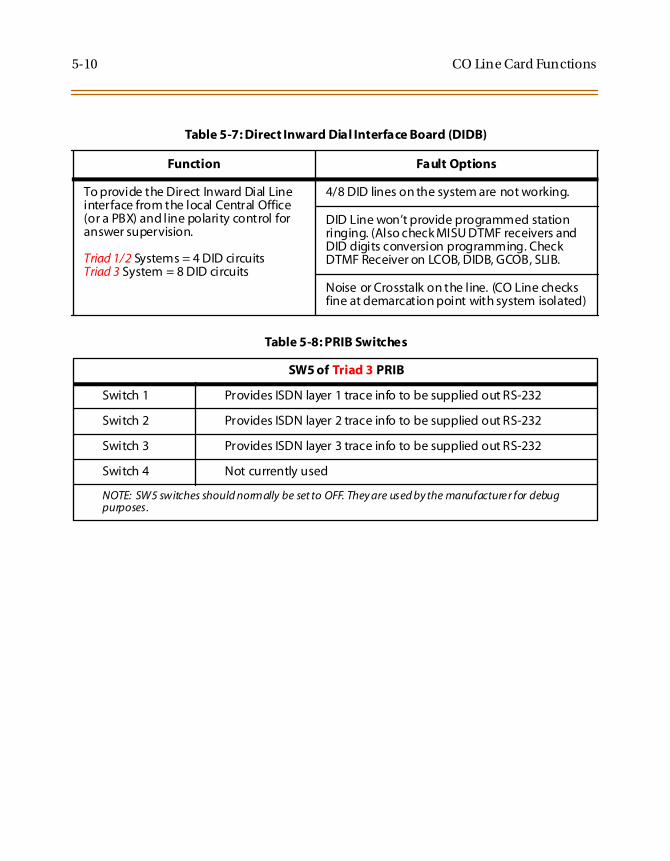
5-10 CO Line Card Functions
Table 5-7: Direct Inward Dial Interface Board (DIDB)
Function Fault Options
To provide the Direct Inward Dial Lineinterface from the local Central Office(or a PBX) and line polarity control foranswer supervision.
Triad 1/2 Systems = 4 DID circuitsTriad 3 System = 8 DID circuits
4/8 DID lines on the system are not working.
DID Line won’t provide programmed stationringing. (Also check MISU DTMF receivers andDID digits conversion programming. CheckDTMF Receiver on LCOB, DIDB, GCOB, SLIB.
Noise or Crosstalk on the line. (CO Line checksfine at demarcation point with system isolated)
Table 5-8: PRIB Switches
SW5 of Triad 3 PRIB
Switch 1 Provides ISDN layer 1 trace info to be supplied out RS-232
Switch 2 Provides ISDN layer 2 trace info to be supplied out RS-232
Switch 3 Provides ISDN layer 3 trace info to be supplied out RS-232
Switch 4 Not currently used
NOTE: SW5 switches should normally be set to OFF. They are used by the manufacture r for debugpurposes.

System Functions 5-11
System Functions
The following functions are related to system resources and the commonequipment boards controlling them.
Table 5-9: Master Processor Board (MPB)
Function Fault Options
Provides system central processingfunction, real time clock, digital (PCM)voice processing and gain control,feature control, customer database,system tone generation and conferencefunctions.
Complete system failure.
Any correctly activated feature not workingproperly.
SMDR and display phone time-of-day incorrect.
Loss of system intercom dial tone and callprocessing tones.
Loss of customer database programming.(Verify status of initialization switch anddatabase backup battery connection)
SMDR RS232C Port inoperative.
Modem Port (or 2nd RS-232C port) inoperative.(Verify Modem Unit, MODU, is installed andprogramming is correct.
Can not program customer database. (Verifystatus of database access switch)
Table 5-10: Memory Expansion Module Unit (MEMU) (Triad 3 only)
Function Fault Options
Provides additional customer databasememory for expanded system featuressuch as expanded Speed Dial numberaccess.
Required when capacity exceeds 48 COLines and 96 Stations.
Unable to access or use features utilizingexpanded memory.

5-12 System Functions
Table 5-11: Modem Unit (MODU)
Function Fault Options
Provides an asynchronous modem foraccess to the system database and faultreporting features from a remote site.
Provides an RS232 port for local access.
Can not access system database programmingremotely. (Also check Modem programming)
Second RS-232C port inoperative (CheckModem Bypass programming).
Table 5-12: Program Module Unit (PMU)
Function Fault Options
Provides the system operating software. The system does not operate without thiscomponent.
Table 5-13: Power Supply Unit (PSU)
Function Fault Options
Provides Direct Current power to thesystem in the form of -48VDC, +30VDC,+5VDC, and -5VDC. LEDs on the PowerSupply Unit (PSU) in each cabinet showpresence of each voltage type.
Provides connections for batteries andcharging current for batteries (optional).
System does not operate (Loss of +5VDC). Alsocheck +5VDC tolerance on PSU.
Analog phones and CO Line do not operate(Loss of -5VDC).
DID Lines do not operate (Loss of -48VDC).
Battery Back-up for system not working. (Alsopress Battery Restart switch on PSU)

System Functions 5-13
Table 5-14: Miscellaneous Interface Board (MISU)
Function Fault Options
Provides external paging, externalcontact control, internal (synthesized)music on hold, music on hold andbackground music inputs, and DTMFreceiver functions (Triad 3 Only).
One or both external paging ports do not work.
Some or none of the 4/6 external controlcontacts do not operate.
Music on hold is not heard (Also check musicsource and music volume control on MISU).
Background music is not heard (Also checkmusic source and background music volumecontrol on MISU).
DTMF single line telephones can not dial.
DISA calls can’t dial system resources after callconnection.
DID Lines won’t ring intended station(s). Alsocheck DID programming.
SIU for functioning properly on Triad 1/2Systems
Table 5-15: DTMF Receiver Unit (DTRU, DTMF-A, DTMF-B)
Function Fault Options
Provides DTMF Receiver functions. DTMF Single Line telephones can not dial out.
DISA calls can’t dial system resources after callconnection.
DID Lines won’t ring intended station(s). Alsocheck DID programming.

5-14 Miscellaneous Functions
Miscellaneous Functions
The following functions are related to other system functions:
Table 5-16: Ring Generator Unit (RGU)
Function Fault Options
Provides ringing voltages of 24VDC and48VDC, and message waiting lampvoltage signaling for single linetelephones.
Each cabinet (Basic & Expansion)supporting SLTs must have an RGUinstalled.
Single line Telephones do not ring when calledon intercom.
Message Waiting signal to single linetelephones with a message waiting lamp doesnot light the lamp. ( Verify correct SLT typeprogrammed, SLT with Msg Lamp, in Station IDprogramming.
Table 5-17: Power Failure Transfer Unit (PFTU)
Function Fault Options
Provides automatic cut-over of up to 6central office lines to up to 6 single linetelephones when system power or thecentral processor fails.
Central office lines connected through thePFTU never available to the system in normaloperation. Check the NORMAL/TEST switch onthe PFTU. Make sure it is in the Normal position.

Station Card Functions 5-15
Station Card Functions
The system can be equipped with various types of station interface cards.Verify each card type and its location in the KSU (Line Number).
Table 5-18: Digital Key Terminal Interface Board (DTIB)
Function Fault Options
Provides the interface for twelve (12)Digital Terminals, DSS/DLS Consoles.
Unable to receive intercom dial tone.
Port transmission characteristics.
Key telephone set inoperative.
Key telephone unable to invoke features.
No LED indications.
Table 5-19: Single Line Interface Board (SLIB) w/MSGU
Function Fault Options
Provides the interface for Single LineTelephones.
Triad 1/2 System = 6 SLTsTriad 3 System = 12 SLTs
SLT can’t receive dial tone.
Poor transmission characteristics.
Also provides for SLTs with/withoutM/W lights.
No Message Wait lights, MSGU inoperative.

5-16 Remote Maintenance
Remote Maintenance
OverviewThe Remote Maintenance feature allows authorized personnel to surveysystem and slot configuration information. This can be done through amodem or data terminal connected via the RS-232C port on the MPB, SIUor SIU2 Module. The commands are entered from a keyboard and arelimited to those listed.
Overview of Maintenance CommandsThere are four basic commands available in the Remote Maintenancefeature. All commands begin with a single character, followed by a space,another character and an optional digit or digits. All commands areterminated with the <r> key.
Maintenance PasswordThe Remote Maintenance feature, like Remote Programming, is enteredvia a six-character alphanumeric string. The password prompt is given bydepressing the <r> key at the device connected to the SIU or SIU2Module port. After the prompt is printed out, the password should beentered followed by the <r> key. Proper entry of the password results inthe maintenance prompt. The Remote Maintenance passwordis: {CONFIG}

Remote Maintenance 5-17
Exit MaintenanceThe Exit command terminates the current Remote Maintenance featuresession. The Exit command format is: maint>x
Figure 5-1: Maintenance Help Menu

5-18 Remote Maintenance
System ConfigurationFigure 5-2: is a configuration of the Triad 1/2/3 Systems displays what isprinted when:
The installer types d<space>s at the maint>prompt.
Figure 5-2: Remote System Configuration
Where:
Column 1 lists the card slot.
Column 2 lists card type of that card slot.
Column 3 lists the firmware version of the card.
Column 4 lists card type and if that card is installed.
Column 5 lists card options.
Column 6 lists card status:
OOS status can indicate the entire card is out of service or a specificstation is not installed or installed but not operational.
INS status can indicate a specific station is installed and operatingcorrectly.
Station ConfigurationFigure 5-3 illustrates a representation of what is printed out for slot onewhen a SLIB is installed in that slot and:
The installer types d<space>s1 at the maint>prompt.

Remote Maintenance 5-19
Figure 5-3: Station Configuration
Column Indicates:
1 Station Number
2 Station Type (keyset, DSS, SLT)
Keyset - ID 0 = Key station
DXX 1 = DSS Map 1DXX 2 = DSS Map 2DXX 3 = DSS Map 3DXX 4 = DSS Map 4DXX 5 = DSS Map 5SLT - ID 6 = SLTSLT w/Lamp - ID 7= SLT w/Message Waiting
3 Status:OOS status can indicate the entire card is out of service; a specific station isnot installed; or installed but not operational.INS status can indicate a specific station is installed and operating correctly.
4 Whether or not the station has an LCD Display
5 State of the device

5-20 Remote Maintenance
CO Line ConfigurationFigure 5-4 illustrates a representation of what is printed out for slot twowhen a LCOB is installed in that slot and:
The installer types d<space>s2 at the maint>prompt.
Figure 5-4: CO Line Configuration
Column Indicates:
1 CO Line Number
2 Status:OOSstatus can indicate the entire card is out of service.INS status can indicate a board station is in-service and operating correctly.
Incoming = Incoming CO line calls are allowedOutgoing = Outgoing CO line calls are allowedBothway = Both incoming and outgoing CO line calls are allowed
For example, Outgoing Enabled indicates the CO line is active in the system.Outgoing Disabled indicates that the Attendant has disabled the CO line foroutgoing access.
3 Whether CO Line is Pulse or DTMF (programmable option)
4 Whether CO Line is a CO Line or a PBX Line (programmable option)
5 CO line State

Remote Maintenance 5-21
Event Trace BufferThe Event Trace Buffer is used to store and dump event traces (up to 30)that occur just prior to a Triad 1/2/3 System soft or hard restart. These canthen be reviewed by authorized personnel to aid in systemtroubleshooting. The basic format for the commands are:
Table 5-20: Event Trace Buffer Commands
Command Function
t<space><return> Displays the current status of the Event trace buffer.
t<space>0<return> Turns the Trace buffer OFF.
t<space>1<return> Turns the Trace buffer ON to record events prior to a softsystem reset.
t<space>2<return> Turns the Trace buffer ON to record events prior to a hardsystem restart.
t<space>3<return> Turns the Trace buffer ON to record events prior to either asoft reset or a hard system restart.
d<space>e<return> Dumps Trace Events stored from last system reset (soft orhard).
d<space>b <return> Permits maintenance personnel to determine the busy statusof all the busy keysets and CO Lines in the system, includingthe T1 lines.
r<space>sXXX<return> Permits a specific station to be reset.
r<space>cXXX <return> Permits a specific CO Line to be reset.
Press the Esc key to abort the Data Dump and return to themaint> prompt.

5-22 Remote System Monitor
DTMF Receiver TraceThe CONFIG utility to allow technicians to take specific DTMF receiversin/out of service. This is useful for troubleshooting DTMF receiverproblems to isolate a specific DTMF receiver that may be faulty.
Connect a terminal to the I/O port 1 on the MPB. At the ENTERPASSWORD prompt type CONFIG and press ENTER.
The basic format for the commands is:
d<space>r<return> - To display the status of all DTMF receivers in thesystem. The display shows the receiver number, cabinet location, cardslot location, receiver status, and state of the receiver.
Making a Receiver Busy:d<space>rXX<return> - Where XX is the specific receiver number tomake busy.
Making a Receiver Available:d<space>rXX<return> - Where XX is the specific receiver number tomake available.
Remote System Monitor
OverviewThe Remote Monitor feature provides remote access to the installedsystem for diagnostic purposes. These capabilities benefit Servicepersonnel enabling them to support the end user remotely. Differentlevels of access, via password, allows authorized personnel to trace,monitor and upload critical information directly from the Triad 1/2/3Systems. This provides a more accurate means of acquiring systeminformation that leads to a quick resolution of problems that may occur.This is all done without interfering with ongoing call processing ornormal system operation, and in many cases may be performed withouta site visit. The built-in 2400 baud modem is used for remote access.
Capabilities allowed and reserved for this high-level troubleshooting are:
Monitor Mode
Enable & Disable Event Trace
Dump Trace Buffer (up-load)

Remote System Monitor 5-23
Monitor PasswordThe Remote Monitor feature, like Remote Maintenance, is entered via asix-character alphanumeric string. The password prompt is given bypressing the <r> key at the device connected to the SIU or SIU2 Module.After the prompt is printed out, the password should be enteredfollowed by the <r> key. Proper entry of the password results in themon>prompt. The Remote Maintenance password is: {ETRACE}
Help Menu (?)A convenient on screen Help Menu is provided by typing [?], thenpressing the <r> key. The following displays:
Figure 5-5: Help Menu
The remote monitor feature is intended for use only under the guidanceand instruction byauthorizedpersonnelfrom VODAVI Technical Support.Care and caution must be observed when using this feature aspermanent damage to the softw are structure can occur.

5-24 Remote System Monitor
Dump Memory DataThree options allow the memory structure to be dumped for viewing.The three options are entered as follows:
c [c] – Dump CO Line memory structure
s [s] – Dump Station memory structure
d [a][a]– Dump a memory address structure
The data obtained from these commands is in hexadecimal format and isused primarily for manufacturer- level support.
Event Trace ModeThe t command enables and disables the Triad 1/2/3 Systems’ Tracemode. While the trace mode is enabled events for the trace desired isdisplayed on the monitor, printer or PC connected to the Triad 1/2/3Systems in an event record. To view the current status of the trace modetype [t]<return> at the mon>prompt, the following displays:
Figure 5-6: Trace Mode Status
Press the Esc key to abort the Data Dump and returns to the mon>prom pt.

Remote System Monitor 5-25
1. To enable an Event Trace, type t<space> (space bar).
2. Then type of trace desired [d], where d is determined as follows:
B = Board event trace (traces events associated with PCBs)
M= Miscellaneous State event trace
P= Pulse Coded Modulation (PCM) traces events associated withvoice communications
C = CO Line (LCOB) States (traces events associated with CO Lineactivity)
S = Station (STA) States (traces events associated with Station activity)
E = Error Messages (traces error messages)
Q = Queue (QUE) Events (traces queuing events, e.g.: DTMF receiver,UCD, LCR, etc.)
D = Device Command (traces commands to peripheral devices).
3. Then enter the specific board, CO line or Station number of the tracedesired or type all , if all board’s, CO line’s or Station’s events aredesired.
1–31 = Board KSU card slot position (CPU = 1)
001-144 = CO Line port
100-351 = Station location
All = All Boards, CO lines or Stations

5-26 Remote System Monitor
4. Then press <r> to enable the trace. A similar screen displays:
Figure 5-7: Enable Event Trace
5. To disable or turn off a particular trace mode, DO NOT ENTER aspecific board, CO Line, or Station Number (i.e.,t<space>s<return> to disable station event trace).
6. To have event traces displayed on the screen, you must first exit theMONitor mode by typingXat the mon> prompt. After you exit theevent(s), the trace begins as shown in Figure 5-8.
Modify Memory CommandThe Modify Memory Command is for Engineering Use only.
Unless instructedby personnelat VOD AVI Technica l Su pp ort,do notleave thetrace mode enabled forextended periods of time. The system dum ps therequested event(s) trace which may use up paper or fill mem ory bufferson the collecting device. It is recommended that the trace events bedisabled (turned off) for all event(s) traces before leaving the system site.
Use of this command can alter or damage the Triad 1/2/3System’soperating database, which can result in system malfunction. If thisoccurs it is necessary to power the system down and re-initialize thedatabase, thencompletely reprogram thecustomerprogram ming data.

Remote System Monitor 5-27
Baud Rate CommandThe Baud Rate command provides a convenient means for changing thebaud rate, for the RS-232C port located on the Master Processor Board(MPB), while in the Monitor mode. To change the baud rate type [B] plusthe desired baud rate, then the enter key.
Exit the Monitor ModeThe Exit command terminates the current Remote Monitorenable/disable session. If Event(s) Trace have been or are still enabled,the event records are displayed only after exiting the MONitor mode. TheExit command format is: mon> x
Figure 5-8: Event Trace
Afterchanging the BaudRate viaBaud Rate comm and, you must changeyour Baud Rate on your Receiver/Terminal.
Unlessinstructed bypersonnel atVODAVITechnicalSupport,donot leavethe trace mode enabled for extendedperiods of time. The system dumpsthe requested event(s) trace which may use up paper or fill memorybuffers on the collecting device. It is recommended that the event tracesbe disabled (turned off) for all event(s) before leaving the system site.

5-28 Remote System Monitor

Index
BBack-Board InstallationTriad 1/2 2-5Triad 3 3-4
Basic KSU InstallationTriad 1 2-8Triad 2 2-11Triad 3 3-7
Basic Rate Interface Board (BRIB) 2-49,3-64Basic Rate Interface Expansion Board(BRIB-E) 3-67
CCable Selection 3-90Caller ID Interface Unit Installation
Triad 1/2 2-75Triad 3 3-90
CO Line Card Functions (testing) 5-9CO/PBX Connections 2-33
DDID Interface Board (DIDB)
Triad 1/2 2-36Triad 3 3-46
Digital Telephone Interface Board(DTIB)
Triad 1/2 2-64Triad 3 3-80
DSS LED/Button Test 5-6Dump Memory Data 5-24
EEKTS 2-51, 3-66Electronic Key Telephone Service 2-
51, 3-66Electronic Telephone Interface Board(ETIB)
Triad 1/2 2-57Triad 3 3-72
Expansion Cabinet (EKSU1), mounting3-8Expansion Cabinet (EKSU2), mounting3-9Expansion KSU (EKSU), mounting 2-14
GGround Start CO Trunk Board (GCOB)3-43
HHeadset Installation
Triad 1/2 2-75Triad 3 3-90
Help Menu (?) 5-23
IISDN and T1 Clocking 2-52, 3-68
KKeyset Button Test 5-5Keyset LCD/LED Test 5-5Keyset Self Test 5-4KSU AC Power Plug 2-21KSU and Power Supply (PS) Installa-tion 2-11KSU Grounding
Triad 1/2 2-20Triad 3 3-12
KSU, programming

ii March 2001
Triad 1/2 2-77Triad 3 3-92
LLightning Protection
Triad 1/2 2-21Triad 3 3-26
Loop Start CO Interface Board (LCOB)Triad 1/2 2-33Triad 3 3-40
MMain Processor Board (MPB) Installa-tion
Triad 1/2 2-24Triad 3 3-28
Maintenance Password 5-16MEMU Installation (Triad 3) 3-33Miscellaneous Functions (testing) 5-14MISU Installation (Triad 3) 3-34Modem Unit (MODU) 2-27
PPCB Installation
Triad 1/2 2-22Triad 3 3-27
PFTU Installation (Triad 3) 3-37Phase Lock Loop Unit (PLLU)
Triad 1/2 2-26Triad 3 3-32
PMU Installation (Triad 3) 3-33Power Line Surge Protection
Triad 1/2 2-21Triad 3 3-26
Power Supply Unit InstallationTriad 1/2 2-18Triad 3 3-14
Power Up Sequence 4-3Preliminary Procedures 4-3Primary Rate Interface Board (PRIB) 2-48, 3-58
RRemote Maintenance 5-16Ring Generator Installation (RGU)
Triad 1/2 2-16Triad 3 3-11
SSingle Line Interface Board (SLIB)
Triad 1/2 2-60Triad 3 3-75
Site PreparationTriad 1/2 2-4Triad 3 3-3
SIU Installation (Triad 1/2) 2-31SIU2 Installation (Triad 3) 3-31Station Card Functions (testing) 5-15System Check-Out 4-1System Commands
DTMF Receiver Trace 5-22Event Trace Buffer 5-21Event Trace Mode 5-24Exit Maintenance 5-17Exit Monitor Mode 5-27Modify Memory 5-26
System Functions (testing) 5-11System Programming and Verification5-3

March 2001 iii
TT-1 Interface Board (T1IB)
Triad 1/2 2-39Triad 3 3-49
Telephone and Terminal (Trouble-shooting) 5-4
WWall Mounting
Digital Telephone (Triad 1/2) 2-74Digital Telephone (Triad 3) 3-89Electronic Telephone (Triad 1/2) 2-
73Electronic Telephone (Triad 3) 3-88
WiringBattery Back-Up (Triad 1/2) 2-67Battery Back-Up (Triad 3) 3-24MISU 2-69MPB and SIU RS232C Port 2-68Station (Triad 1/2) 2-69Station (Triad 3) 3-84

iv March 2001

www.vodavi.com
©2000 Vodavi Technology, Inc.VODAVI is a registered trademark of Vodavi Technology, Inc. 8050-12
we’re talking technology