installation unitary energy recovery ventilator … · fresh air supply and transferred to the...
TRANSCRIPT
PAGE 1
I - Ship ping And Pack ing List
Package 1 of 1 contains:
1 - Energy Recovery Ventilator w/ Transition Assembly1 - Outdoor Fresh Air Hood with Filter 1 - Outdoor Exhaust Air Hood with Barometric Damper 1 - Balancing Damper Assembly1 - Bag Assembly
1 - Roll of ¾" x 1 ¼" gasket 1 - 272" of 1
8" x ½" gasket 1 - Field Wiring Harness for Low Voltage - Self-tapping screws - Gold Screws - Installation Instructions
II - Ship ping Dam age
Check unit for shipping damage. Receiving party shouldcontact last carrier immediately if shipping damage isfound.
III - Gen eral
These instructions are intended as a general guide and donot supersede local codes in any way. Authorities havingjurisdiction should be consulted before installation.
IV - Re quire ments
When installed, the unit must be electrically wired andgrounded in accordance with local codes or, in theabsence of local codes, with the current National ElectricCode, ANSI/NFPA No. 70.
V - Ap pli ca tion
Unitary Energy Recovery Ventilator (UERV) are used with3 to 6 ton rooftop units equipped with a balancingdamper assembly. These wheels conserve energy bymixing warmer air with cooler air in the following manner:
Re cov ery Wheel Mode
The Recovery Wheel mode is accomplished by twoblowers providing continuous exhaust of stale indoor airand replacement by equal amount of outdoor air. Energyrecovery is achieved by slowly rotating the energyrecovery wheel within the cassette frame work. In winter,the UERV adsorbs heat and moisture from the exhaust airstream during one half of a complete rotation and givesthem back to the cold, drier intake air supply during theother half rotation. In summer, the process is automaticallyreversed. Heat and moisture are absorbed from incomingfresh air supply and transferred to the exhaust air stream.This process allows outdoor air ventilation rates to beincreased by factors of three or more without additionalenergy penalty or increase in size of heating or airconditioning systems.
VI - Rig ging Unit For Lift ing
1. Maximum weight of unit is —- 750 Lbs. (Crated)
2. Remove crating. Then remove access panel toretrieve bag assembly. Replace access panel.
3. All panels must be in place for rigging.
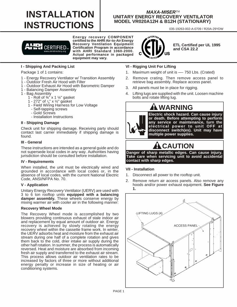
4. Lifting lugs are supplied with the unit. Loosen machinebolts and rotate lifting lug.
CAUTIONDanger of sharp metallic edges. Can cause injury.Take care when servicing unit to avoid accidentalcontact with sharp edges.
WARNINGElectric shock hazard. Can cause injuryor death. Before attempting to performany service or maintenance, turn theelectrical power to unit OFF atdisconnect switch(es). Unit may havemultiple power supplies.
VII - In stal la tion
1. Disconnect all power to the rooftop unit.
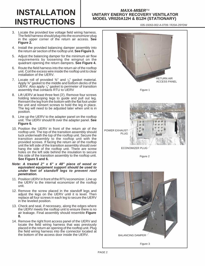
2. Remove return air access panels. Also remove anyhoods and/or power exhaust equipment. See Figure1.
MAXA-MI$ERÔUNITARY ENERGY RECOVERY VENTILATORMODEL VR020A12H & B12H (STATIONARY)
INSTALLATIONINSTRUCTIONS
035-19263-002-A-0709 / R20A-29YDW
ACCESS PANEL
LIFTING LUGS (4)
ETL Certified per UL 1995and CSA 22.2
Energy recovery COMPONENTcertified to the AHRI Air-to-Air Energy Recovery Ventilation EquipmentCertification Program in accordancewith AHRI Standard 1060-2000.Actual performance in packagedequipment may vary.
PAGE 2
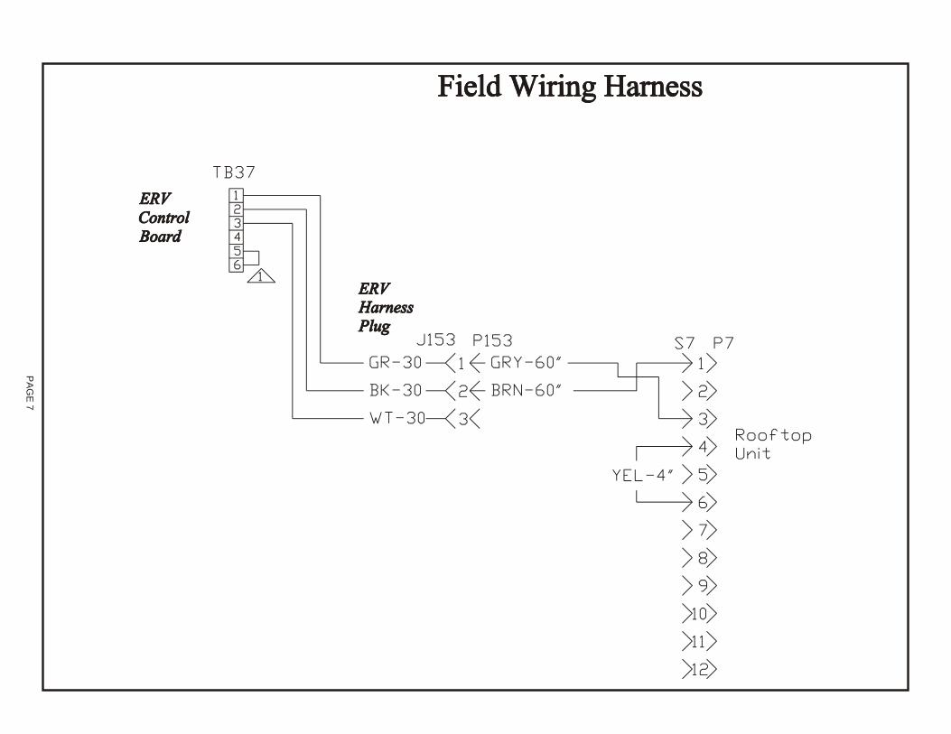
3. Locate the provided low voltage field wiring harness.The field harness should plug into the economizer plug in the upper corner of the return air access. SeeFigure 2.
4. Install the provided balancing damper assembly intothe return air section of the rooftop unit. See Figure 3.
5. Adjust the balancing damper for the minimum air flowrequirements by loosening the wingnut on thequadrant opening the return dampers. See Figure 4.
6. Route the field harness into the return air of the rooftopunit. Coil the excess wire inside the rooftop unit to clear installation of the UERV.
7. Locate roll of provided ¾" and 18" gasket material.
Apply ¾" gasket to the middle and bottom decks of theUERV. Also apply 1
8" gasket to perimeter of transitionassembly that contacts RTU to UERV
8. Lift UERV at least three feet (3'). Remove four screwsholding telescoping legs to guide and pull out leg.Reinsert the leg from the bottom with the flat foot under the unit and reinsert screws to hold the leg in place.The leg will need to be adjusted later when unit is inposition.
9. Line up the UERV to the adapter panel on the rooftopunit. The UERV should fit over the adapter panel. SeeFigure 6.
10. Position the UERV in front of the return air of therooftop unit. The top of the transition assembly shouldtuck underneath the top of the rooftop unit. Secure thetransition assembly to the rooftop unit with theprovided screws. If facing the return air of the rooftopunit the left side of the transition assembly should overhang the side of the rooftop unit. There are screwholes on the left side behind the insulation to securethis side of the transition assembly to the rooftop unit.See Figure 5 and 6.
Note: A treated 2" x 6" x 48" piece of wood orequivalent equipment support should be used tounder feet of standoff legs to prevent roofpenetration.
11. Position UERV in front of the RTU economizer. Line up the UERV to the internal economizer of the rooftopunit.
12. Remove the screw placed in the standoff legs andadjust the legs on the UERV until it is level. Thenreplace all four screws in each leg to secure the UERVin the leveled position.
13. Check and seal, if necessary, along the edges wherethe UERV meets the rooftop unit to ensure there is noair leakage. Final assembly should resemble Figure 8.
14. Remove the right front access panel of the UERV andlocate the field wiring harness that was previouslyplaced in the return air opening of the rooftop unit. Plug the field wiring harness into the connector located atthe bottom of the access door inside the UERV.
RETURN AIRACCESS PANEL
Figure 1
Figure 3
Figure 2
BALANCING DAMPER
POWER EXHAUST PLUG
ECONOMIZER PLUG
MAXA-MI$ERÔUNITARY ENERGY RECOVERY VENTILATORMODEL VR020A12H & B12H (STATIONARY)
INSTALLATIONINSTRUCTIONS
035-19263-002-A-0709 / R20A-29YDW

PAGE 3
15. All electrical connections must conform to any localcodes and the current National Electric Codes (NEC)and Canadian Electric Code (CEC). Refer closely towiring diagram in unit and/or in these instructions forproper connections. Refer to the unit nameplate for the minimum circuit ampacity and maximum over currentprotection size. Electrical data is listed on unit ratingplate and motor nameplates.
16. Connect line voltage power to UERV unit from rooftopunit disconnect switch through the knock out. Connectthe line voltage to the UERV control box per the wiringdiagram. Figure 9 shows the control box and wiring.
17. Ground unit with a suitable ground connection eitherthrough unit supply wiring or earth ground.
Note: Unit voltage entries must be sealed weathertight after wiring is complete.
18. Replace access panels onto the UERV unit andsecure.
19. Restore power to unit.
20. Start system up to verify operation.
21 Balancing is done by removing the plastic plugs indoor panels (4 total).
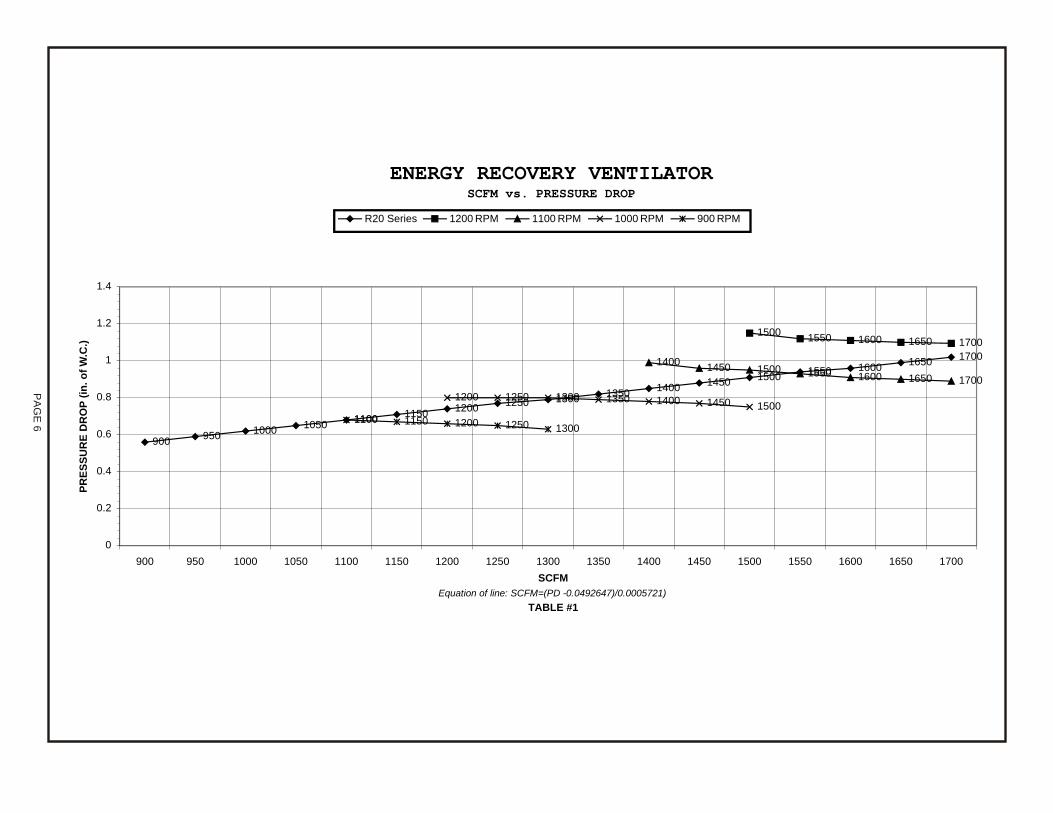
22. With a manometer measure pressure drop [ inches ofwater column] across the top half of UERV (top holesin door panel). Unit CFM is determined by referring toTable #1. If CFM values are not per design, adjustinternal dampers inside the rooftop unit. This isaccomplished by removing door panel at the return airopening, loosing wingnut on damper, then adjustreturn damper in the return airstream and re-tightenwingnut. Replace door panel and repeatmeasurement method.
23. Place plastic plugs back into door panels.
24. Cleanup once UERV is operating properly. Caulk anyopen joints, holes or seams to make the unitcompletely air and water tight.
25. Fill out installation checklist and start-up sheet in backof this instruction.
26. Leave this instruction manual with owner or in anenvelope to be kept near the unit.
VIII - Op er a tion
How It Works
The unit contains an Energy Recovery Wheel (ERW) thatis a new concept in rotary air-to-air heat exchanger.Designed as a packaged unit for ease of installation andmaintenance, only matching up to rooftop unit with aninternal balancing damper and connection of electricalpower is required to make the system operational. Theconcept consists of a unique rotary energy recovery wheelthat rotates in and out of fresh air streams within a heavyduty, permanently installed blower cabinet that providesready access to all internal components. The media ispolymeric material that is coated and permanently bondedwith a dry desiccant for total enthalpy recovery. The wheelis belt driven by PSC motor and drive belt.
Figure 5
Figure 6
Figure 4
QUADRANT
MAXA-MI$ERÔUNITARY ENERGY RECOVERY VENTILATORMODEL VR020A12H & B12H (STATIONARY)
INSTALLATIONINSTRUCTIONS
035-19263-002-A-0709 / R20A-29YDW
ADAPTOR UNDER UNIT TOP
ADAPTOR UNDER UERV TOP

PAGE 4
When slowly rotating through counter flowing exhaust andfresh air streams the UERV adsorbs sensible heat andlatent heat from the warmer air stream and transfer thistotal energy to the cooler air stream during the second halfof its rotating cycle. Rotating at 60 revolutions per minute,the wheel provides constant flow of energy from warmer to cooler air stream. The large energy transfer surface andlaminar flow through the wheel causes this constant flowof recovered energy to represent up to 85% of thedifference in total energy contained within the two airstreams.
Sensible and latent heat are the two components of totalheat. Sensible heat is energy contained in dry air and latent heat is the energy contained within the moisture of the air.The latent heat load from the outdoor fresh air on an airconditioning system can often be two to three times that ofthe sensible heat load and in the winter it is a significantpart of a humidification heat load.
During both the summer and winter, the UERV transfersmoisture entirely in the vapor phase. This eliminates wetsurfaces that retain dust and promote fungal growth as well as the need for a condensate pan and drain to carry water.
Because it is constantly rotating when in the air stream, theUERV is always being cleared by air, first in one directionthen the other. Because it is always dry, dust or otherparticles impinging on the surface during one half cycle,are readily removed during the next half cycle.
Additional Information for Options are provided inOptions Manual.
Re cov ery Mode
On a thermostat call for blower operation in heating,cooling or continuous blower, the ERW will rotate betweenfresh air and exhaust air streams. Both the fresh air andexhaust air blowers will also be operating to overcome theair resistance of the UERV.
IX - Sys tem Check
1. Disconnect main power.
2. Remove control access panel and apply 24 volts to low voltage terminal strip at "TB37-1(+) and TB37-2(-)".
3. Restore power to unit. Observe UERV wheel rotationand both fresh air and exhaust air blower areoperating.
4. Verify that the UERV (3) three phase blower motorsare phased sequentially ensuring correct rotation andoperation.
a) Disconnect power.
b) Reverse any two field power leads to the UERV.
c) Reapply power.
A - Re turn Damper Set tings
Manually adjust position of dampers. This is accomplishedby loosing and tightening screws on slide damper.
B - Blower Speed Ad just ment
Blower speed selection is accomplished by changing thesheave setting on both fresh air and exhaust air blowers.Both blowers are factory set at "closed" for maximum
Figure 7
Figure 8
MAXA-MI$ERÔUNITARY ENERGY RECOVERY VENTILATORMODEL VR020A12H & B12H (STATIONARY)
INSTALLATIONINSTRUCTIONS
035-19263-002-A-0709 / R20A-29YDW
OPTIONAL EQUIPMENT SUPPORT
DELTA PRESSURE(FRESH AIR)
DELTA PRESSURE(EXHAUST AIR)
airflow. To determine air flow setting, external staticpressure readings will need to be read across the UERV.See Figure 8 for location to take pressure readings.
C - Air Bal anc ing Ad just ment
1. Remove plastic plugs in door panels(4 total).
2. With a manometer measure pressure drop [inches ofwater column] across top half of UERV (top holes indoor panel). Unit CFM is determined then by referringto Table #1. If CFM values are not per design, adjustintake motor sheave and repeat measure method.
3. Repeat the same process for the bottom half of UERV.If CFM values are not per design, adjust internaldampers inside the rooftop unit. This is accomplishedby removing door panel at the return air opening,loosing wingnut on damper, then adjust return damperin the return airstream and re-tighten wingnut.Replace door panel and repeat measurement method.
4. Place plastic plugs back in to door panels.

PAGE 5
X - Main te nance
Motor MaintenanceAll motors use prelubricated sealed bearings; no furtherlubrication is necessary.
Mechanical InspectionMake visual inspection of dampers, linkage assembliesand erv rotating bearings during routine maintenance.Filters should be checked periodically and cleaned whennecessary. Filter is located in fresh air hoods. DO NOTreplace permanent filters with throwaway type filters.
Belt AlignmentProper alignment is essential to maintain long V-Belt life.Belt alignment should be checked every time beltmaintenance is performed, each time the belt is replaced,and whenever sheaves are removed or installed.
Belt InstallationAlways move the drive unit forward so the belt can beeasily slipped into the groove without forcing them. Neverforce the belt into a sheave with a screw driver or wedge.You will damage the fabric and break the cords. It isrecommended that the pulley center distances be offset by¾" for proper length. This will allow the motor assembly toslide forward to remove belt and backward for belt tension.
Belt TensionMeasure the span length (center distance between pulleys when belt is snug). Mark center of span, then apply a force(6 to 9 Lbs on new belts) perpendicular to the span largeenough to deflect the belt 164" for every inch in span length.
En ergy Recovery Wheel Main te nanceFour pie-shaped ERW seg ments are seated on stopsbe tween the stain less steel spring re tain ers, se cured tothe hub and rim of wheel. An nual in spec tion of the selfc lean ing wheel is rec om mended. With powerdis con nected, re move UERV ac cess pan els (rear) andun plug (J150 & P150). Re fer to wir ing di a gram in thisin struc tion man ual. Each seg ment is se cured in place by astain less steel spring re tainer lo cated on wheel rim.Re move one end of the stain less steel spring re tainer fromthe slot in the wheel rim and re move. Do the same on thenext re tainer. Re move seg ment and wash with wa terand/or mild de ter gent. Re place seg ment by re vers ing theabove pro ce dure. See Fig ure 9. Dis col or ation andstain ing of UERV seg ment does not af fect its per for mance. Only ex ces sive buildup of for eign ma te rial need bere moved. If the seg ment ap pears ex ces sively dirty, itshould be cleaned to en sure max i mum op er at ingef fi ciency. Thor oughly spray plas tic sur face withhouse hold cleaner such as Fan tas ticâ or equiv a lentmid dle de ter gent and gently rinse with warm wa ter us ing asoft brush to re move heavier ac cu mu la tion. Shake excesswater from segment and replace in reverse of removalinstructions.
FIGURE 9
HUB
SEGMENT
SPOKE
SEGMENT RETAINER CATCHWHEEL RIM
SEGMENT RETAINER
MAXA-MI$ERÔUNITARY ENERGY RECOVERY VENTILATORMODEL VR020A12H & B12H (STATIONARY)
INSTALLATIONINSTRUCTIONS
035-19263-002-A-0709 / R20A-29YDW
PA
GE
6
ENERGY RECOVERY VENTILATORSCFM vs. PRESSURE DROP
900950
10001050
11001150
12001250 1300
13501400
14501500
1550 16001650
1700
15001550 1600 1650 1700
14001450 1500 1550 1600 1650 1700
1200 1250 1300 1350 1400 1450 15001100 1150 1200 1250 1300
0
0.2
0.4
0.6
0.8
1
1.2
1.4
900 950 1000 1050 1100 1150 1200 1250 1300 1350 1400 1450 1500 1550 1600 1650 1700
SCFM
Equation of line: SCFM=(PD -0.0492647)/0.0005721)
TABLE #1
PR
ES
SU
RE
DR
OP
(in
.o
fW
.C.)
R20 Series 1200 RPM 1100 RPM 1000 RPM 900 RPM
PA
GE
7

R20A-29YDW
UERV UNIT SCHE MATIC DIAGRAM
Notes:1. Remove jumper to install field optional low ambient switch.2. Step-down transformer assembly for 460 volt units.3. Selective voltage terminal for proper unit voltage4. Optional low ambient switch.5. Optional motorized intake damper.6. Optional stop, start and jog control.7. Matching adapter harness (provided) to connect with rooftop unit. For energy
management systems connect +24v to green and common 24v to black.
PAGE 8
COM PO NENT CODE
A131 Fixed Re lay Board
B26 Mo tor, Ex haust Air
B27 Mo tor, Fresh Air
B28 Mo tor, Des ic cant Wheel
B30 Mo tor, Damper (Op tional)
C23 Ca paci tor, Wheel Mo tor
DL43 De lay, Cy cle Timer (Op tional)
F29 Fuse
J33 Jack, Cy cle Con trol (Op tional)
J34 Jack, Cy cle Con trol Har ness (Op tional)
J40 Jack, Cy cle (Op tional)
J48 Jack, Con trol Box (Fresh Air)
J50 Jack, Con trol Box (Wheel)
J148 Jack, Fresh Air Mo tor Har ness
J150 Jack, Wheel Mo tor Har ness
J151 Jack, Ex haust Air Mo tor Har ness
J152 Jack, Trans former (High Volt age)
J153 Jack, Field Har ness
J160 Jack, Damper Mo tor Har ness
K94 Re lay, On/Off (Op tional)
K163 Con tac tor, Ex haust Air Mo tor
K164 Con tac tor, Fresh Air Mo tor
P33 Plug, Cy cle Con trol (Op tional)
P34 Plug, Cy cle Con trol Har ness (Op tional)
P40 Plug, Wheel Cy cle (Op tional)
P48 Plug, Fresh Air Mo tor Har ness
P51 Plug, Ex haust Air Mo tor Har ness
P56 Plug, Damper Mo tor Har ness
P148 Plug, Fresh Air Mo tor
P150 Plug, Wheel Mo tor
P151 Plug, Ex haust Air Mo tor
P152 Plug, Trans former (High Volt age)
P153 Plug, Field Har ness
P160 Plug, Damper Mo tor
S23 Ther mo stat - Low Am bi ent (Op tional)
S26 Switch, Low Am bi ent (Op tional)
S51 Switch, Door
S125 Switch, Am bi ent Over ride (Op tional)
T27 Trans former, Con trol
T28 Trans former, Step- down (Op tional)
WIRE COLOR CODE
BK Black
BL Blue
GR Green
GY Gray
OR Orange
PK Pink
RD Red
WH White
YL Yel low
PAGE 9
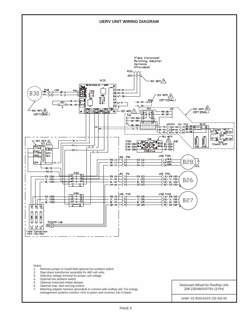
Unit#: 01- R20-01XX-23/-33/-43
Des ic cant Wheel for Roof top Unit208- 230/460V/575V (3 PH)
UERV UNIT WIR ING DIAGRAM
Notes:1. Remove jumper to install field optional low ambient switch.2. Step-down transformer assembly for 460 volt units.3. Selective voltage terminal for proper unit voltage4. Optional low ambient switch.5. Optional motorized intake damper.6. Optional stop, start and jog control.7. Matching adapter harness (provided) to connect with rooftop unit. For energy
management systems connect +24v to green and common 24v to black.
PA
GE
10
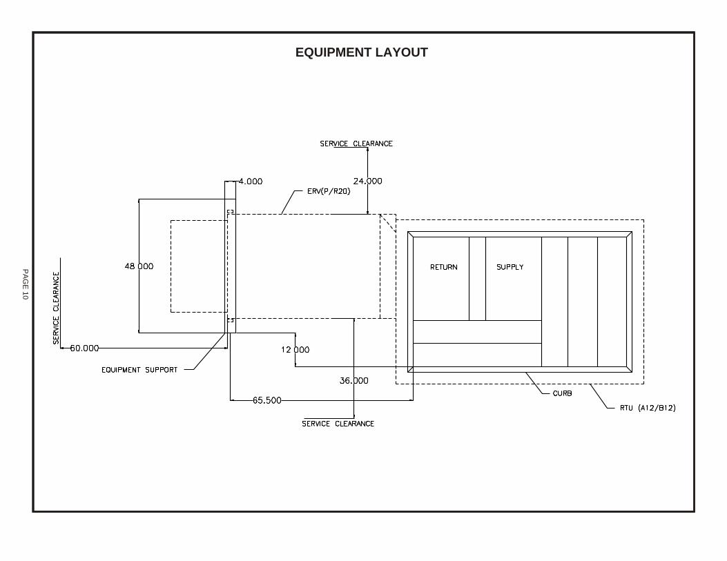
EQUIP MENT LAY OUT
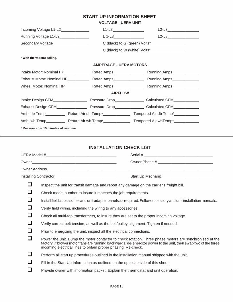
START UP INFORMATION SHEET VOLTAGE - UERV UNIT
In com ing Volt age L1-L2 L1-L3 L2-L3
Run ning Volt age L1-L2 L 1-L3 L2-L3
Sec ond ary Volt age C (black) to G (green) Volts*
C (black) to W (white) Volts*
* With ther mo stat call ing.
AM PER AGE - UERV MO TORS
In take Mo tor: Nom i nal HP Rated Amps Run ning Amps
Ex haust Mo tor: Nom i nal HP Rated Amps Run ning Amps
Wheel Mo tor: Nom i nal HP Rated Amps Run ning Amps
AIR FLOW
In take De sign CFM Pres sure Drop Cal cu lated CFM
Ex haust De sign CFM Pres sure Drop Cal cu lated CFM
Amb. db Temp Re turn Air db Temp* Tem pered Air db Temp*
Amb. wb Temp Re turn Air wb Temp* Tem pered Air wbTemp*
* Mea sure af ter 15 min utes of run time
IN STAL LA TION CHECK LIST
UERV Model # Se rial #
Owner Owner Phone #
Owner Ad dress
In stall ing Con trac tor Start Up Me chanic
q Inspect the unit for transit damage and report any damage on the carrier’s freight bill.
q Check model number to insure it matches the job requirements.
q Install field accessories and unit adapter panels as required. Follow accessory and unit installation manuals.
q Verify field wiring, including the wiring to any accessories.
q Check all multi-tap transformers, to insure they are set to the proper incoming voltage.
q Verify correct belt tension, as well as the belt/pulley alignment. Tighten if needed.
q Prior to energizing the unit, inspect all the electrical connections.
q Power the unit. Bump the motor contactor to check rotation. Three phase motors are synchronized at thefactory. If blower motor fans are running backwards, de-energize power to the unit, then swap two of the threeincoming electrical lines to obtain proper phasing. Re-check.
q Perform all start up procedures outlined in the installation manual shipped with the unit.
q Fill in the Start Up Information as outlined on the opposite side of this sheet.
q Provide owner with information packet. Explain the thermostat and unit operation.
PAGE 11
NOTES
Unitary 5005 NormanProducts York OKGroup Drive 73069
Supercedes: 035-19263-001-A-1108Sub ject to change with out no tice. Printed in U.S.A.Copy right © by Uni tary Prod ucts Group 2005. All rights re served.
035-19263-002-A-0709R20A-29YDW