installation - s&c electric company routine switchgear testing ... 2 s&c instruction sheet...
TRANSCRIPT

S&C Vista® Underground Distribution Switchgear UnderCover™, Vault-Mounted, and Pad-Mounted Styles
January 22, 2018
© S&C Electric Company 1997-2018, all rights reserved Instruction Sheet 681-505
Installation
Table of Contents
Section Page Section Page
IntroductionQualified Persons . . . . . . . . . . . . . . . . . . . . . . . . . . . . . 2Read this Instruction Sheet . . . . . . . . . . . . . . . . . . . . . . 2Retain this Instruction Sheet . . . . . . . . . . . . . . . . . . . . . 2Proper Application . . . . . . . . . . . . . . . . . . . . . . . . . . . . . 2Warranty . . . . . . . . . . . . . . . . . . . . . . . . . . . . . . . . . . . . 2
Safety InformationUnderstanding Safety-Alert Messages . . . . . . . . . . . . . 3Following Safety Instructions . . . . . . . . . . . . . . . . . . . . 3Replacement Instructions and Labels . . . . . . . . . . . . . . 3Location of Safety Labels . . . . . . . . . . . . . . . . . . . . . . . . 4
Inspection and HandlingPacking . . . . . . . . . . . . . . . . . . . . . . . . . . . . . . . . . . . . . 5Inspection . . . . . . . . . . . . . . . . . . . . . . . . . . . . . . . . . . . 5Handling . . . . . . . . . . . . . . . . . . . . . . . . . . . . . . . . . . . . 6
Installation—UnderCover and Vault-Mounted Styles
Switchgear Placement . . . . . . . . . . . . . . . . . . . . . . . . . . 7Cable Terminations . . . . . . . . . . . . . . . . . . . . . . . . . . . . 7Grounding . . . . . . . . . . . . . . . . . . . . . . . . . . . . . . . . . . . 8Fault Indicators . . . . . . . . . . . . . . . . . . . . . . . . . . . . . . . . 8
Installation—Pad-Mounted StyleEnclosure Removal . . . . . . . . . . . . . . . . . . . . . . . . . . . . 9 Tank Placement . . . . . . . . . . . . . . . . . . . . . . . . . . . . . . 11Cable Terminations . . . . . . . . . . . . . . . . . . . . . . . . . . . 11Enclosure Placement . . . . . . . . . . . . . . . . . . . . . . . . . . 12 Grounding . . . . . . . . . . . . . . . . . . . . . . . . . . . . . . . . . . 13Fault Indicators . . . . . . . . . . . . . . . . . . . . . . . . . . . . . . . 13Completing the Installation . . . . . . . . . . . . . . . . . . . . . 14
Gas Pressure GaugeUnderstanding the Gas Pressure Gauge . . . . . . . . . . 15Gauge Needle Fluctuations from Rapid Ambient
Temperature Changes . . . . . . . . . . . . . . . . . . . . . . . 15
Dielectric TestingRoutine Switchgear Testing . . . . . . . . . . . . . . . . . . . . 16Dc Cable Testing and Fault Locating . . . . . . . . . . . . . . 16Very Low Frequency (VLF) Cable Testing . . . . . . . . . . 18Fault-Interrupter Testing . . . . . . . . . . . . . . . . . . . . . . . . 19Resistance Measurement . . . . . . . . . . . . . . . . . . . . . . 19
2 S&C Instruction Sheet 681-505
Introduction
Qualified Persons WARNINGThe equipment covered by this publication must be installed, operated, and maintained by qualified persons who are knowledgeable in the installation, operation, and maintenance of underground electric power distribution equipment along with the associated hazards . A qualified person is one who is trained and competent in:
• The skills and techniques necessary to distinguish exposed live parts from nonlive parts of electrical equipment
• The skills and techniques necessary to determine the proper approach distances corresponding to the voltages to which the qualified person will be exposed
• The proper use of the special precautionary techniques, personal protective equipment, insulating and shielding materials, and insulated tools for working on or near exposed energized parts of electrical equipment
These instructions are intended only for such qualified persons . They are not intended to be a substitute for adequate training and experience in safety procedures for this type of equipment .
Read this Instruction Sheet
Read this instruction sheet thoroughly and carefully before installing or operating your S&C Vista Underground Distribution Switchgear. Familiarize yourself with the Safety Information on pages 3 and 4. The latest version of this publication is available online in PDF format at sandc.com/en/support/product-literature.
Retain this Instruction Sheet
This instruction sheet is a permanent part of your S&C Vista Underground Distribution Switchgear. Designate a location where you can easily retrieve and refer to this publication.
Proper Application WARNINGThe equipment in this publication must be selected for a specific application . The application must be within the ratings furnished for the equipment . Ratings for this gear are listed on a ratings label at the front of the switchgear . See Specification Bulletin 681-31 for more information .
Warranty The warranty and/or obligations described in S&C’s standard conditions of sale, as set forth in Price Sheet 150, plus any special warranty provisions, as set forth in the applicable product-line specification bulletin, are exclusive . The remedies provided in the former for breach of these warranties shall constitute the immediate purchaser’s or end user’s exclusive remedy and a fulfillment of all seller liability . In no event shall the seller’s liability to the immediate purchaser or end user exceed the price of the specific product that gives rise to the immediate purchaser’s or end user’s claim . All other warranties, whether express or implied or arising by operation of law, course of dealing, usage of trade or otherwise, are excluded . The only warranties are those stated in Price Sheet 150, and THERE ARE NO EXPRESS OR IMPLIED WARRANTIES OF MERCHANTABILITY OR FITNESS FOR A PARTICULAR PURPOSE . ANY EXPRESS WARRANTY OR OTHER OBLIGATION PROVIDED IN PRICE SHEET 150 IS GRANTED ONLY TO THE IMMEDIATE PURCHASER AND END USER, AS DEFINED THEREIN . OTHER THAN AN END USER, NO REMOTE PURCHASER MAY RELY ON ANY AFFIRMATION OF FACT OR PROMISE THAT RELATES TO THE GOODS DESCRIBED HEREIN, ANY DESCRIPTION THAT RELATES TO THE GOODS, OR ANY REMEDIAL PROMISE INCLUDED IN PRICE SHEET 150 .
The seller’s warranties are contingent upon the installation and adjustment of S&C Vista Underground Distribution Switchgear in accordance with S&C’s applicable instruction sheets, data sheets, and/or data bulletins .
S&C Instruction Sheet 681-505 3
Understanding Safety-Alert Messages
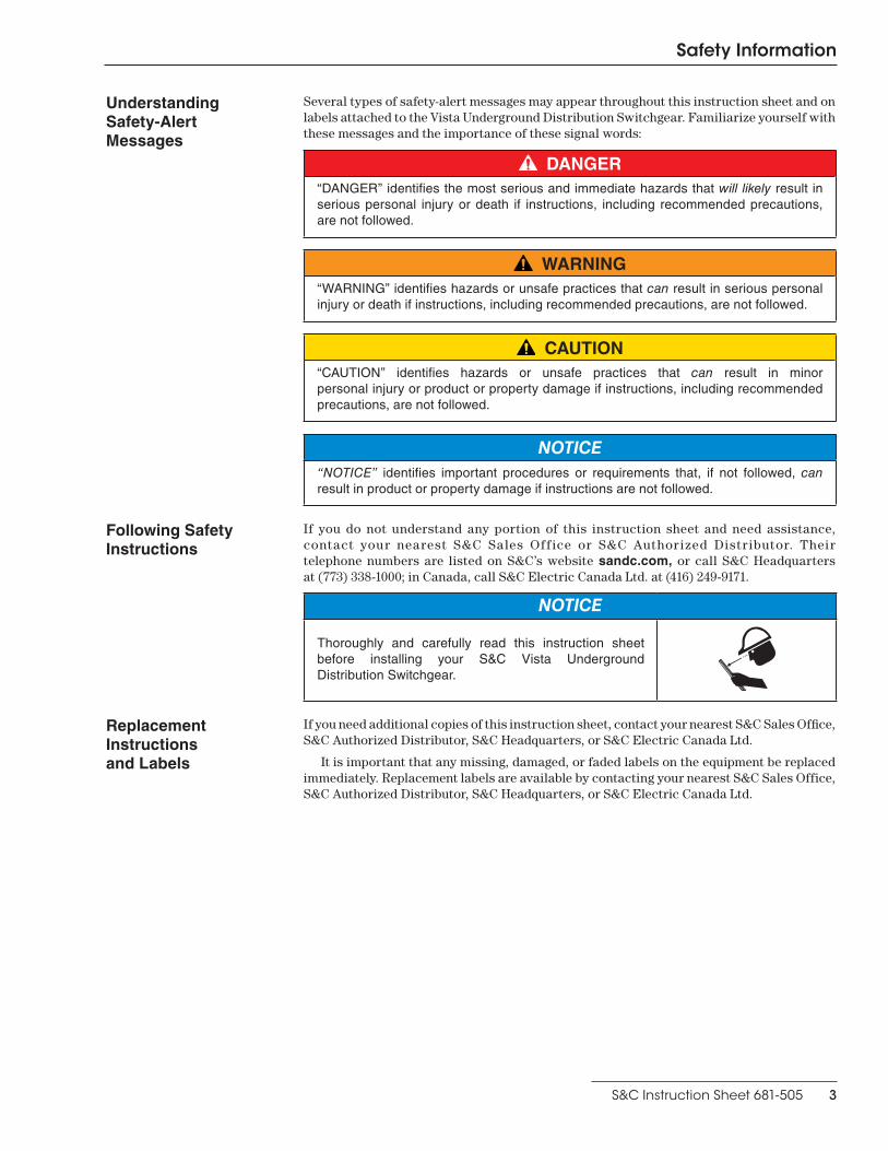
Several types of safety-alert messages may appear throughout this instruction sheet and on labels attached to the Vista Underground Distribution Switchgear. Familiarize yourself with these messages and the importance of these signal words:
DANGER“DANGER” identifies the most serious and immediate hazards that will likely result in serious personal injury or death if instructions, including recommended precautions, are not followed .
WARNING“WARNING” identifies hazards or unsafe practices that can result in serious personal injury or death if instructions, including recommended precautions, are not followed .
CAUTION“CAUTION” identifies hazards or unsafe practices that can result in minor personal injury or product or property damage if instructions, including recommended precautions, are not followed .
NOTICE“NOTICE” identifies important procedures or requirements that, if not followed, can result in product or property damage if instructions are not followed .
Following Safety Instructions
If you do not understand any portion of this instruction sheet and need assistance, contact your nearest S&C Sales Off ice or S&C Author ized Distr ibutor. Their telephone numbers are listed on S&C’s website sandc.com, or call S&C Headquarters at (773) 338-1000; in Canada, call S&C Electric Canada Ltd. at (416) 249-9171.
NOTICE
Thoroughly and carefully read this instruction sheet before installing your S&C Vista Underground Distribution Switchgear .
Replacement Instructions and Labels
If you need additional copies of this instruction sheet, contact your nearest S&C Sales Office, S&C Authorized Distributor, S&C Headquarters, or S&C Electric Canada Ltd.
It is important that any missing, damaged, or faded labels on the equipment be replaced immediately. Replacement labels are available by contacting your nearest S&C Sales Office, S&C Authorized Distributor, S&C Headquarters, or S&C Electric Canada Ltd.
Safety Information

4 S&C Instruction Sheet 681-505
Safety Information
Location of Safety Labels
Reorder Information for Safety Labels
Location Safety-Alert Message Description Part Number
A WARNING Keep Out—Hazardous Voltage Inside G-6681
B DANGER Hazardous Voltage—Always Consider Circuits and Components Live . . . G-6700
C DANGER Never Drill Into Tank—Hazardous Voltage, Contains Pressurized SF6 Gas G-6682
D DANGER Keep Away—Hazardous Voltage (“Mr . Ouch”) G-6699
E WARNING Check Gas Pressure Before Operating Switchgear G-6686
F WARNING Always Test Voltage Indicator For Proper Operation G-6689
G WARNING Always Visually Confirm Blade PositionG-6693 G-6694
(Option “-L2”)
C D
Top of switchgear
Pad-mounted enclosure
E
F
G
B
A

Inspection and Handling
S&C Instruction Sheet 681-505 5
Packing UnderCover Style and Vault-Mounted Style Vista Underground Distribution Switchgear are shipped in a wooden crate.
Pad-Mounted Style Vista switchgear (enclosure with separate tank) is fastened to a wood skid. The tank is shipped within the enclosure. At the first opportunity, remove all packing materials (cardboard, paper, foam padding, etc.) from the outside of the pad-mounted enclosure. This will prevent the finish from being damaged by rainwater absorbed by the packing materials and will also prevent wind-induced abrasion from loose cardboard.
Inspection Examine the shipment for external evidence of damage as soon after receipt as possible, preferably before removal from the carrier’s conveyance. Check the bill of lading to make sure that all shipping skids, crates, and containers listed thereon are present.
If there is visible loss and/or damage:
1. Notify the delivering carrier immediately.
2. Ask for a carrier inspection.
3. Note condition of shipment on all copies of the delivery receipt.
4. File a claim with the carrier.
If concealed damaged is discovered:
1. Notify the delivering carrier within 15 days of receipt of shipment.
2. Ask for a carrier inspection.
3. File a claim with the carrier.
Also notify S&C Electric Company in all instances of loss and/or damage
Inspection and Handling
6 S&C Instruction Sheet 681-505
Handling
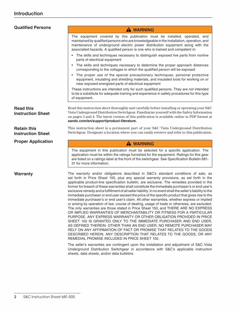
WARNINGWhen handling an enclosure or tank with an overhead hoist, observe standard lifting practices as well as the general instructions below. Failure to follow these precautions can result in serious personal injury or equipment damage.
STEP 1. Remove and retain the anchor brackets tie wrapped to the enclosure or tank grounding pad. Use 6-foot (1829-mm) or longer hoist slings of equal length to prevent damage to the enclosure or tank during lifting. (Four-foot (1219-mm) hoist slings are acceptable for two-way and three-way enclosures and tanks.) See Figures 1 through 3.
STEP 2. Arrange the hoist slings to distribute lifting forces equally between the lifting tabs.
STEP 3. Avoid sudden starts and stops.
Figure 2. UnderCover Style and tank for pad-mounted style.
Figure 3. Vault-mounted style.
Figure 1. Enclosure for pad-mounted style.

S&C Instruction Sheet 681-505 7
Installation—UnderCover and Vault-Mounted Styles
Switchgear PlacementSTEP 1. Remove any packing or foam from around the
viewing window and check the gas pressure gauge to make sure it is in the green zone. Contact S&C Electric Company if the gas pressure gauge is not in the green zone. See the “Gas Pressure Gauge” section on page 15 for more information. Remove the switchgear from its crate and lift the gear into place, observing the precautions given in the “Handling” section on page 6. See Figure 4.
STEP 2. Secure the switchgear in place in accordance with the pull box or wall brackets provided by the user.
Cable Terminations
DANGERBefore energizing the switchgear, replace the shipping covers on all bushing and bushing wells with elbows or insulated protective caps . Failure to replace the shipping covers on all bushings and bushing wells with elbows or insulated protective caps can result in a flashover and serious personal injury or death .
STEP 3. Remove the shipping covers from the bushings and bushing wells. See Figure 5.
Figure 4. Switchgear is bolted to skid in four places for shipment.
Shipping coversBushings shown with covers removedShipping
covers
Ground in accordance with user’s standard grounding practice (grounding not shown)
Yellow shipping covers are provided for bushing wells
Shipping covers removed
Fault-interrupter and load-interrupter switch terminals are equipped with 200-ampere bushing wells or 600-ampere bushings, as specified
Black shipping covers are provided for bushings
Figure 5. Shipping covers on bushings and bushing wells.

8 S&C Instruction Sheet 681-505
CAUTIONALWAYS follow proper cable-installation practices . When installing cable that will be attached to the switchgear, provide a strain-relief segment to minimize the load on the bushings . Cables must be allowed to expand and flex without putting a significant load on the bushings . For a pit, either loop the cable in the pit or bring it into the pit horizontally and up to the gear at a 90º angle . Failure to follow these precautions can result in damage to the bushings and bushing wells and subsequent leakage of SF6 insulating gas.
STEP 4. Terminate the cables with the elbows, following the elbow manufacturer's instructions. See Figure 6.
GroundingSTEP 5. Connect the cable concentric-neutral ground wires
to the grounding system as appropriate.
STEP 6. Connect the ground pad of the switchgear to the system ground facility in accordance with the user’s standard grounding practice. See Figure 7.
STEP 7. Use the equivalent of 4/0 copper (or cable sized in accordance with the user’s standard practice) in either a single or multiple connection to realize the maximum momentary rating of the switchgear. For a multiple connection, cables smaller than 1/0 copper or equivalent should not be used.
Fault IndicatorsFault indicators are to be furnished by the user and installed in accordance with the manufacturer’s instructions.
Figure 7. Connect the switchgear ground pad to a suitable earth ground. Ground in accordance with user's standard grounding practice (grounding not shown).
Switchgear ground pad
Elbows and inserts supplied by user
Bushing and bushing well interfaces conform to ANSI/ IEEE Standard 386 to accept standard elbows and inserts
Installation—UnderCover and Vault-Mounted Styles
Figure 6. Terminate cables with elbows.

Installation—Pad-Mounted Style
S&C Instruction Sheet 681-505 9
Enclosure RemovalSTEP 1. Loosen the pentahead bolts securing the hinged
roofs to the enclosure using a pentahead socket wrench with extender or a pentahead tool. See Figure 8.
STEP 2. Lift the hinged roofs upward and secure them with the holders. See Figure 9.
STEP 3. Remove the front panel from the operation compartment and the upper front panel from the termination compartment by loosening the fasteners securing the panels in place and lifting the panels upward. Set the panels aside in a safe, clean place. See Figure 10 on page 10.
Pentaheadwrench with extender
Upper front panel (not shown)
Holder
Hinged roofs
Operation compartment
Termination compartment
Front panel
Figure 8. Loosen the pentahead bolts.
Figure 9. Open the enclosure and secure the roofs with the holders.

Installation—Pad-Mounted Style
10 S&C Instruction Sheet 681-505
It is important to keep track of which side of the enclosure is the termination side and which side is the operation side after the panels are removed. The operation side panel is larger and has the larger opening. See Figure 10.
STEP 4. Unbolt the enclosure from the skid and remove it from the tank, observing the precautions given in the “Handling” section on page 6. Set the enclosure aside in a protected area. See Figure 11.
Removing enclosure from tank
Figure 11. Unbolt and remove the enclosure from the skid.
Front panel removed
Upper front panel removed (not shown)
Operation compartment
Termination compartment
Figure 10. Remove the front panel and upper front panel.
Installation—Pad-Mounted Style
S&C Instruction Sheet 681-505 11
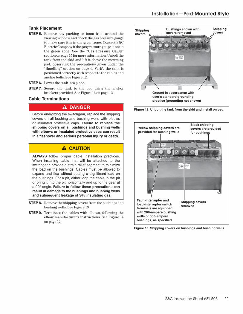
Tank PlacementSTEP 5. Remove any packing or foam from around the
viewing window and check the gas pressure gauge to make sure it is in the green zone. Contact S&C Electric Company if the gas pressure gauge is not in the green zone. See the “Gas Pressure Gauge” section on page 15 for more information. Unbolt the tank from the skid and lift it above the mounting pad, observing the precautions given under the “Handling” section on page 6. Verify the tank is positioned correctly with respect to the cables and anchor bolts. See Figure 12.
STEP 6. Lower the tank into place.
STEP 7. Secure the tank to the pad using the anchor brackets provided. See Figure 16 on page 12.
Cable Terminations
DANGERBefore energizing the switchgear, replace the shipping covers on all bushing and bushing wells with elbows or insulated protective caps . Failure to replace the shipping covers on all bushings and bushing wells with elbows or insulated protective caps can result in a flashover and serious personal injury or death .
CAUTION
ALWAYS follow proper cable installation practices . When installing cable that will be attached to the switchgear, provide a strain relief segment to minimize the load on the bushings . Cables must be allowed to expand and flex without putting a significant load on the bushings . For a pit, either loop the cable in the pit or bring it into the pit horizontally and up to the gear at a 90º angle . Failure to follow these precautions can result in damage to the bushings and bushing wells and subsequent leakage of SF6 insulating gas.
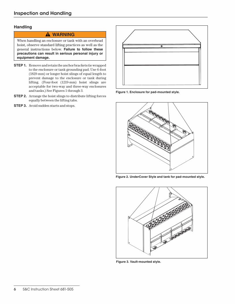
STEP 8. Remove the shipping covers from the bushings and bushing wells. See Figure 13.
STEP 9. Terminate the cables with elbows, following the elbow manufacturer's instructions. See Figure 14 on page 12.
Figure 12. Unbolt the tank from the skid and install on pad.
Shipping covers
Bushings shown with covers removed
Shipping covers
Ground in accordance with user’s standard grounding practice (grounding not shown)
Yellow shipping covers are provided for bushing wells
Shipping covers removed
Fault-interrupter and load-interrupter switch terminals are equipped with 200-ampere bushing wells or 600-ampere bushings, as specified
Black shipping covers are provided for bushings
Figure 13. Shipping covers on bushings and bushing wells.

Installation—Pad-Mounted Style
12 S&C Instruction Sheet 681-505
Enclosure Placement
CAUTIONWhen installing the pad-mounted enclosure over the tank, place the side of the enclosure with the “Termination Compartment” label over the termina-tors and the side of the enclosure with the “Operation Compartment” label over the operating mechanisms . This will ensure the compartments are properly identified and the panels are in their correct locations . The operation compartment side panel is larger .
STEP 10. Lift the enclosure into place over the tank, observing the precautions given in the “Handling” section on page 6. See Figure 15.
STEP 11. Refer to the catalog dimensional drawing and verify the enclosure compartments are positioned correctly and the enclosure is properly aligned with respect to the anchor bolts.
STEP 12. Secure the enclosure to the pad using the anchor brackets provided. See Figure 16.
NOTICECarefully follow the catalog drawing during enclosure placement . The position of the enclosure on the skid should not be used as a guide for placing the enclosure on the pad .
Elbows and inserts supplied by user
Bushing and bushing well interfaces conform to ANSI/ IEEE Standard 386 to accept standard elbows and inserts
Figure 14. Terminate cables with elbows.
Figure 15. Lift the enclosure and position it over the anchor bolt holes.
Lowering the enclosure over tank
Figure 16. Anchor bracket detail.
Gasket
Concrete pad
Enclosure
1.5-in. (38.1-mm) min.
Four .625-in.dia. anchor bolts by user Anchor bracket
by S&C

Installation—Pad-Mounted Style
S&C Instruction Sheet 681-505 13
GroundingSTEP 13. Connect the cable concentric-neutral ground wires
to the grounding system as appropriate.
STEP 14. Connect the ground pad of the tank and the ground pad inside the enclosure to the system ground facility in accordance with the user’s standard grounding practice. See Figure 17.
STEP 15. Use the equivalent of 4/0 copper (or cable sized in accordance with the user’s standard practice) in either a single or multiple connection to realize the maximum momentary rating of the switchgear. For a multiple connection, cables smaller than 1/0 copper or equivalent should not be used. See Figure 18.
Fault IndicatorsFault indicators are to be furnished by the user and installed in accordance with the manufacturer’s instructions. Optional mounting provisions for fault indicators (catalog number suffix “-F1” or “-F2”) are available for pad-mounted style switchgear. If mounting provisions are specified, mount the fault indicators on the mounting brackets and attach the associated sensors to the cables below the cable terminations.
Figure 17. Connect the switchgear ground pad to a suitable earth ground.
Tank ground pad
Ground in accordance with user’s standard grounding practice (grounding not shown)
Enclosure ground pad
Figure 18. Connect the enclosure ground pad to a suitable earth ground.

Installation—Pad-Mounted Style
14 S&C Instruction Sheet 681-505
Completing the InstallationSTEP 16. A resilient closed-cell gasket on the bottom flange
of the enclosure protects the finish from being scratched during installation, and isolates it from the alkalinity of a concrete foundation. This gasket also helps to seal the enclosure to the foundation, to guard against entry of wildlife, insects, or weeds, and to discourage tampering. See Figure 19.
In the event the gasket cannot compensate for an uneven foundation, grout the bottom of the enclosure as necessary. Any grout applied should be recessed enough to permit caulking. To com-plete the installation, caulk around the bottom of the enclosure; a weatherproof temperature vulcanizing (RTV) silicon-rubber compound is recommended. Apply a suitable compound to fill the spaces between the cable and the conduit, and cap all empty conduits to prevent the entry of moisture and wildlife.
STEP 17. Reinstall the front panel of the operation compartment and the upper front panel of the termination compartment. These panels are not interchangeable. Lower the hinged roofs and secure them with the pentahead bolts. Then insert a padlock into each hasp. See Figure 20.
STEP 18. Wipe down the exterior of the enclosure with a clean, damp cloth. Refinish any scratches or abrasions with S&C touch-up finish and red-oxide primer, which are available in aerosol spray cans. Order Catalog Number 9999-058 for olive green finish, 9999-080 for light gray finish, and 9999-061 for red-oxide primer. No other finish or primer is approved. The area to be touched up should be cleaned to remove all oil and grease. Sand the area to remove any traces of rust that may be present, and make sure that all edges are feathered before applying primer. See Figure 21.
Red-oxide primer
Touch-up finish
Bottom of enclosure
Upper frontpanel (not shown)
Termination compartment
Padlock
RTV silicon-rubber caulk
Operation compartment Front panel
Figure 19. Caulk around the bottom of the enclosure using silicone-Rubber caulk.
Figure 20. Secure the switchgear with a padlock.
Figure 21. Touch up any scratches with red-oxide primer and touch-up finish.
S&C Instruction Sheet 681-505 15
Gas Pressure Gauge
15 S&C Instruction Sheet 681-505
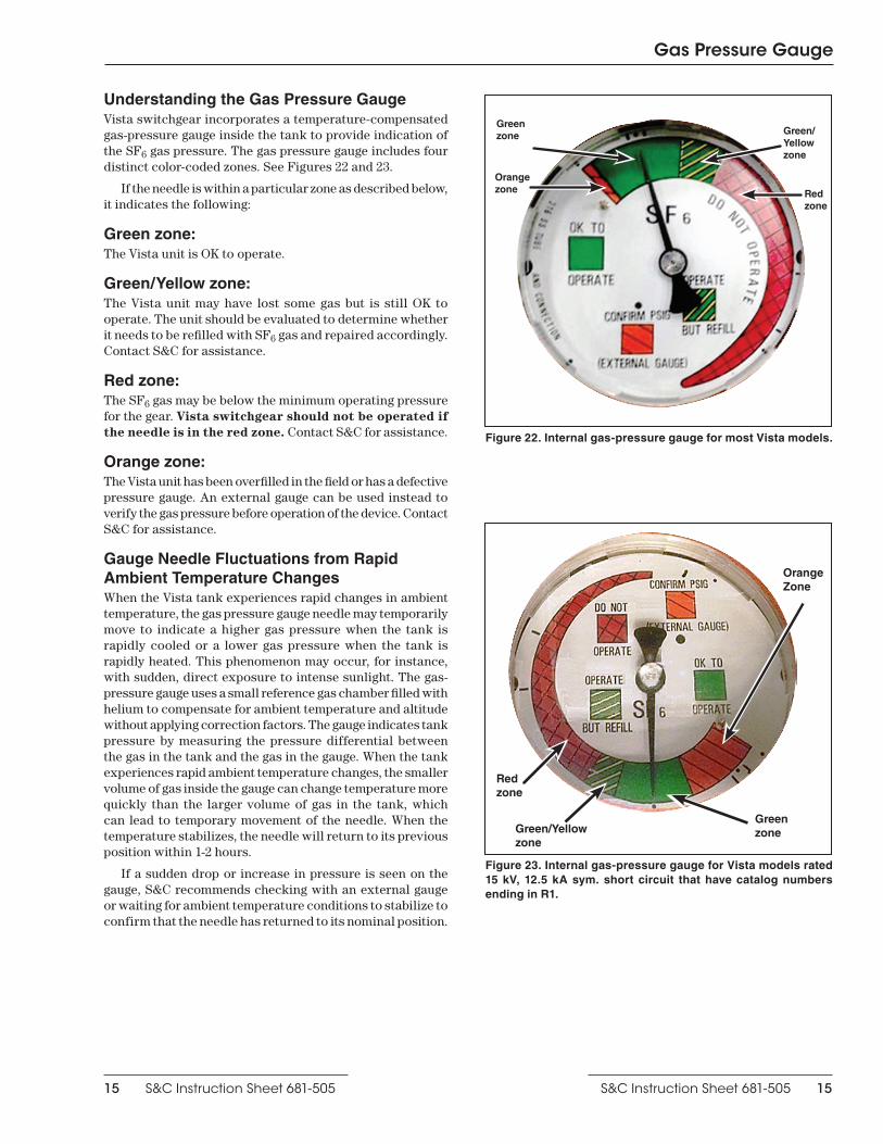
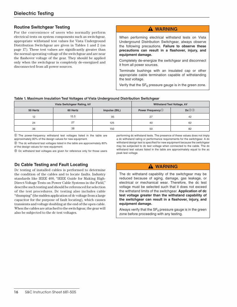
Understanding the Gas Pressure GaugeVista switchgear incorporates a temperature-compensated gas-pressure gauge inside the tank to provide indication of the SF6 gas pressure. The gas pressure gauge includes four distinct color-coded zones. See Figures 22 and 23.
If the needle is within a particular zone as described below, it indicates the following:
Green zone:The Vista unit is OK to operate.
Green/Yellow zone:The Vista unit may have lost some gas but is still OK to operate. The unit should be evaluated to determine whether it needs to be refilled with SF6 gas and repaired accordingly. Contact S&C for assistance.
Red zone:The SF6 gas may be below the minimum operating pressure for the gear. Vista switchgear should not be operated if the needle is in the red zone. Contact S&C for assistance.
Orange zone:The Vista unit has been overfilled in the field or has a defective pressure gauge. An external gauge can be used instead to verify the gas pressure before operation of the device. Contact S&C for assistance.
Gauge Needle Fluctuations from Rapid Ambient Temperature ChangesWhen the Vista tank experiences rapid changes in ambient temperature, the gas pressure gauge needle may temporarily move to indicate a higher gas pressure when the tank is rapidly cooled or a lower gas pressure when the tank is rapidly heated. This phenomenon may occur, for instance, with sudden, direct exposure to intense sunlight. The gas- pressure gauge uses a small reference gas chamber filled with helium to compensate for ambient temperature and altitude without applying correction factors. The gauge indicates tank pressure by measuring the pressure differential between the gas in the tank and the gas in the gauge. When the tank experiences rapid ambient temperature changes, the smaller volume of gas inside the gauge can change temperature more quickly than the larger volume of gas in the tank, which can lead to temporary movement of the needle. When the temperature stabilizes, the needle will return to its previous position within 1-2 hours.
If a sudden drop or increase in pressure is seen on the gauge, S&C recommends checking with an external gauge or waiting for ambient temperature conditions to stabilize to confirm that the needle has returned to its nominal position.
Figure 22. Internal gas-pressure gauge for most Vista models.
Figure 23. Internal gas-pressure gauge for Vista models rated 15 kV, 12.5 kA sym. short circuit that have catalog numbers ending in R1.
Green/Yellow zone
Green zone
Red zone
Green/Yellow zone
Red zone
Green zone
Orange zone
Orange Zone
Dielectric Testing
16 S&C Instruction Sheet 681-505
Dc Cable Testing and Fault LocatingDc testing of installed cables is performed to determine the condition of the cables and to locate faults. Industry standards like IEEE 400, “IEEE Guide for Making High-Direct-Voltage Tests on Power Cable Systems in the Field,” describe such testing and should be referenced for selection of the test procedures. Dc testing also includes cable “thumping” (the sudden application of dc voltage from a large capacitor for the purpose of fault locating), which causes transients and voltage doubling at the end of the open cable. When the cables are attached to the switchgear, the gear will also be subjected to the dc test voltages.
Routine Switchgear TestingFor the convenience of users who normally perform electrical tests on system components such as switchgear, appropriate withstand test values for Vista Underground Distribution Switchgear are given in Tables 1 and 2 (on page 17). These test values are significantly greater than the normal operating voltage of the switchgear and are near the flashover voltage of the gear. They should be applied only when the switchgear is completely de-energized and disconnected from all power sources.
WARNING
When performing electrical withstand tests on Vista Underground Distribution Switchgear, always observe the following precautions . Failure to observe these precautions can result in a flashover, injury, and equipment damage.
Completely de-energize the switchgear and disconnect it from all power sources .
Terminate bushings with an insulated cap or other appropriate cable termination capable of withstanding the test voltage .
Verify that the SF6 pressure gauge is in the green zone .
WARNING
The dc withstand capability of the switchgear may be reduced because of aging, damage, gas leakage, or electrical or mechanical wear . Therefore, the dc test voltage must be selected such that it does not exceed the withstand limits of the switchgear . Application of dc test voltage greater than the withstand capability of the switchgear can result in a flashover, injury, and equipment damage.
Always verify that the SF6 pressure gauge is in the green zone before proceeding with any testing .
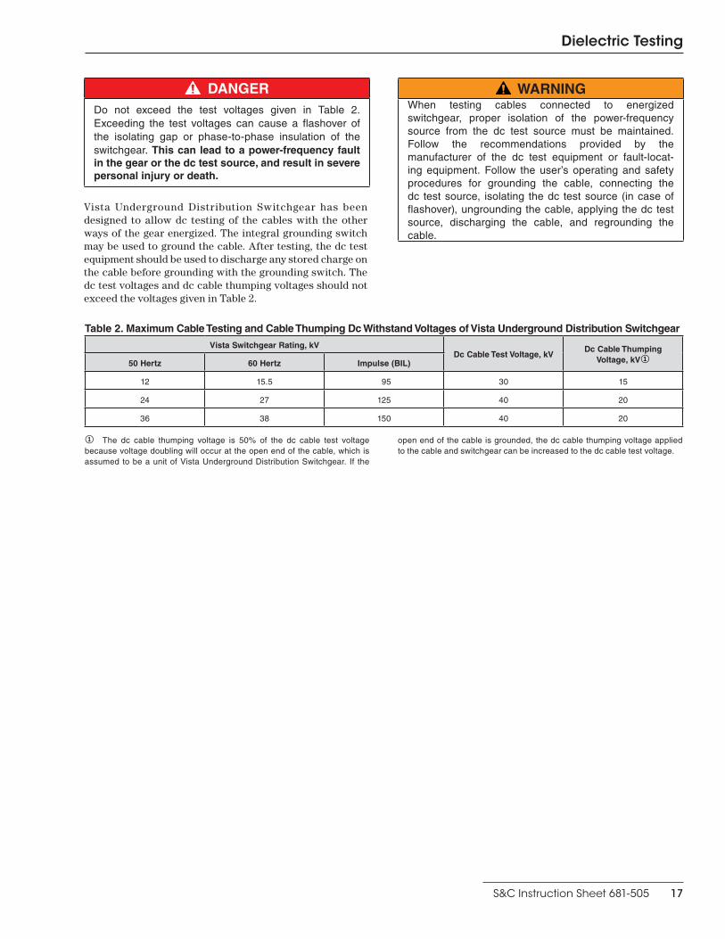
Table 1. Maximum Insulation Test Voltages of Vista Underground Distribution Switchgear
Vista Switchgear Rating, kV Withstand Test Voltage, kV
50 Hertz 60 Hertz Impulse (BIL) Power Frequency① Dc②③
12 15 .5 95 27 42
24 27 125 40 62
36 38 150 50 82
① The power-frequency withstand test voltages listed in the table are approximately 80% of the design values for new equipment .② The dc withstand test voltages listed in the table are approximately 80% of the design values for new equipment .③ Dc withstand test voltages are given for reference only for those users
performing dc withstand tests . The presence of these values does not imply a dc withstand rating or performance requirements for the switch gear . A dc withstand design test is specified for new equipment because the switchgear may be subjected to dc test voltage when connected to the cable . The dc withstand test values listed in the table are approximately equal to the ac peak test voltage .
Dielectric Testing
S&C Instruction Sheet 681-505 17
DANGERDo not exceed the test voltages given in Table 2 . Exceeding the test voltages can cause a flashover of the isolating gap or phase-to-phase insulation of the switchgear . This can lead to a power-frequency fault in the gear or the dc test source, and result in severe personal injury or death.
Vista Underground Distribution Switchgear has been designed to allow dc testing of the cables with the other ways of the gear energized. The integral grounding switch may be used to ground the cable. After testing, the dc test equipment should be used to discharge any stored charge on the cable before grounding with the grounding switch. The dc test voltages and dc cable thumping voltages should not exceed the voltages given in Table 2.
WARNINGWhen testing cables connected to energized switchgear, proper isolation of the power-frequency source from the dc test source must be maintained . Follow the recommendations provided by the manufacturer of the dc test equipment or fault-locat-ing equipment . Follow the user’s operating and safety procedures for grounding the cable, connecting the dc test source, isolating the dc test source (in case of flashover), ungrounding the cable, applying the dc test source, discharging the cable, and regrounding the cable .
Table 2. Maximum Cable Testing and Cable Thumping Dc Withstand Voltages of Vista Underground Distribution Switchgear
Vista Switchgear Rating, kVDc Cable Test Voltage, kV
Dc Cable Thumping Voltage, kV①50 Hertz 60 Hertz Impulse (BIL)
12 15 .5 95 30 15
24 27 125 40 20
36 38 150 40 20
① The dc cable thumping voltage is 50% of the dc cable test voltage because voltage doubling will occur at the open end of the cable, which is assumed to be a unit of Vista Underground Distribution Switchgear . If the
open end of the cable is grounded, the dc cable thumping voltage applied to the cable and switchgear can be increased to the dc cable test voltage .
Dielectric Testing
18 S&C Instruction Sheet 681-505
Very Low Frequency (VLF) Cable TestingIEEE Standard 400.2, “IEEE Guide for Field Testing of Shielded Power Cable Systems Using Very Low Frequency (VLF) (less than 1 Hz),” addresses the application of 0.01- to 1-Hz high-voltage ac excitation as one means for evaluating a shielded power cable system during an acceptance test or a maintenance test. The cable system must be taken out of service for this testing.
An acceptance test is a field test made after installation of the power cable system, including terminations and joints, but before the cable system is placed in normal service. A maintenance test is a field test made during the operating life of a power cable system to detect deterioration and to check serviceability of the system.
VLF cable testing may subject the Vista Underground Distribution Switchgear to the ac test voltage when the cables are attached to the switchgear. S&C recommends that the Vista switchgear be completely de-energized and disconnected from all power sources when performing VLF cable testing. However, Vista switchgear has been designed to allow VLF testing of the cables with the other ways of the gear energized, if necessary. A load-interrupter switch or fault interrupter can be placed in its Grounded position to ground the cable. Before proceeding with the VLF cable testing, verify that the Vista switchgear SF6 pressure gauge is in the green zone.
Upon completion of the VLF cable testing, or an interrup-tion in the testing, the test set must be turned off to discharge the cable circuit and test set. Then, the cable system must be grounded.
The VLF sinusoidal waveform test voltages applied to the Vista switchgear must not exceed the voltages listed in Table 3.
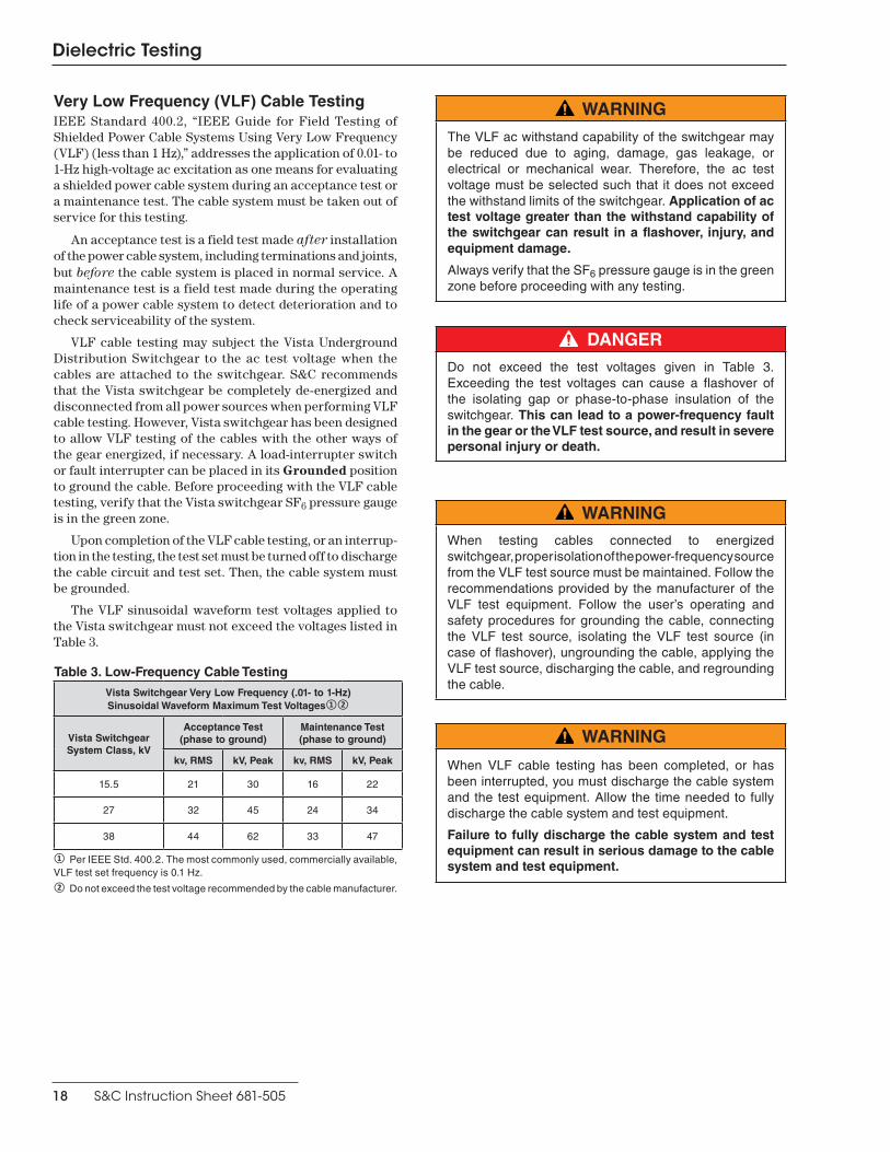
Table 3. Low-Frequency Cable Testing
Vista Switchgear Very Low Frequency (.01- to 1-Hz)Sinusoidal Waveform Maximum Test Voltages①②
Vista SwitchgearSystem Class, kV
Acceptance Test(phase to ground)
Maintenance Test(phase to ground)
kv, RMS kV, Peak kv, RMS kV, Peak
15 .5 21 30 16 22
27 32 45 24 34
38 44 62 33 47
① Per IEEE Std . 400 .2 . The most commonly used, commercially available, VLF test set frequency is 0 .1 Hz .② Do not exceed the test voltage recommended by the cable manufacturer .
DANGERDo not exceed the test voltages given in Table 3 . Exceeding the test voltages can cause a flashover of the isolating gap or phase-to-phase insulation of the switchgear . This can lead to a power-frequency fault in the gear or the VLF test source, and result in severe personal injury or death.
WARNING
The VLF ac withstand capability of the switchgear may be reduced due to aging, damage, gas leakage, or electrical or mechanical wear . Therefore, the ac test voltage must be selected such that it does not exceed the withstand limits of the switchgear . Application of ac test voltage greater than the withstand capability of the switchgear can result in a flashover, injury, and equipment damage.
Always verify that the SF6 pressure gauge is in the green zone before proceeding with any testing .
WARNINGWhen testing cables connected to energized switchgear, proper isolation of the power-frequency source from the VLF test source must be maintained . Follow the recommendations provided by the manufacturer of the VLF test equipment . Follow the user’s operating and safety procedures for grounding the cable, connecting the VLF test source, isolating the VLF test source (in case of flashover), ungrounding the cable, applying the VLF test source, discharging the cable, and regrounding the cable .
WARNING
When VLF cable testing has been completed, or has been interrupted, you must discharge the cable system and the test equipment . Allow the time needed to fully discharge the cable system and test equipment .
Failure to fully discharge the cable system and test equipment can result in serious damage to the cable system and test equipment.

Dielectric Testing
S&C Instruction Sheet 681-505 19
Fault-Interrupter TestingWhen performing dielectrical tests on Vista Underground Distribution Switchgear, the vacuum fault interrupters will not be subject to voltage across the open gap because the disconnect switch isolates the vacuum interrupters from the test voltage. Because the vacuum interrupter will not be energized across the open gap, there is no exposure to the X-rays normally associated with high-voltage testing of vacuum devices. Routine testing of the vacuum fault interrupters is not recommended. For those users who desire to test the vacuum interrupters, contact the nearest S&C Sales Office for specific instructions.
Resistance Measurement
DANGERDe-energize the Vista Underground Distribution Switchgear before performing the resistance measurements described in this procedure . Follow all applicable safety procedures . Failure to de-energize the Vista Underground Distribution Switchgear before taking resistance measurements can result in serious injury or death .
Resistance measurements are used to look for areas of the gear that may exhibit poor contact between current carrying parts.
Resistance measurements are taken using a four-terminal measuring device that provides at least 100 amperes of current to the main circuit. Resistance measurements should be taken from the bushing conductor across each way to the same phase on each way of the unit. For example, a measure-ment would be taken from Way 1 Phase A to Way 2 Phase A, from Way 2 Phase A to Way 3 Phase A, from Way 1 Phase A to Way 3 Phase A, from Way 1 Phase B to Way 2 Phase B; etc.
To measure resistance, perform the following procedure:
STEP 1. Clamp the two current-carrying probes of the resistance-measuring device to the bushing conductors of the current-carrying path to be measured. See Figure 23. In this example the resistance is being taken between Way 1 Phase A and Way 2 Phase A.
Figure 23. Connecting the resistance measuring device.▲
▲ Resistance measurements shown without safety gloves . Please adhere to your company’s standards in regards to using hand PPE when taking resis-tance measurements .
Dielectric Testing
20 S&C Instruction Sheet 681-505
STEP 2.
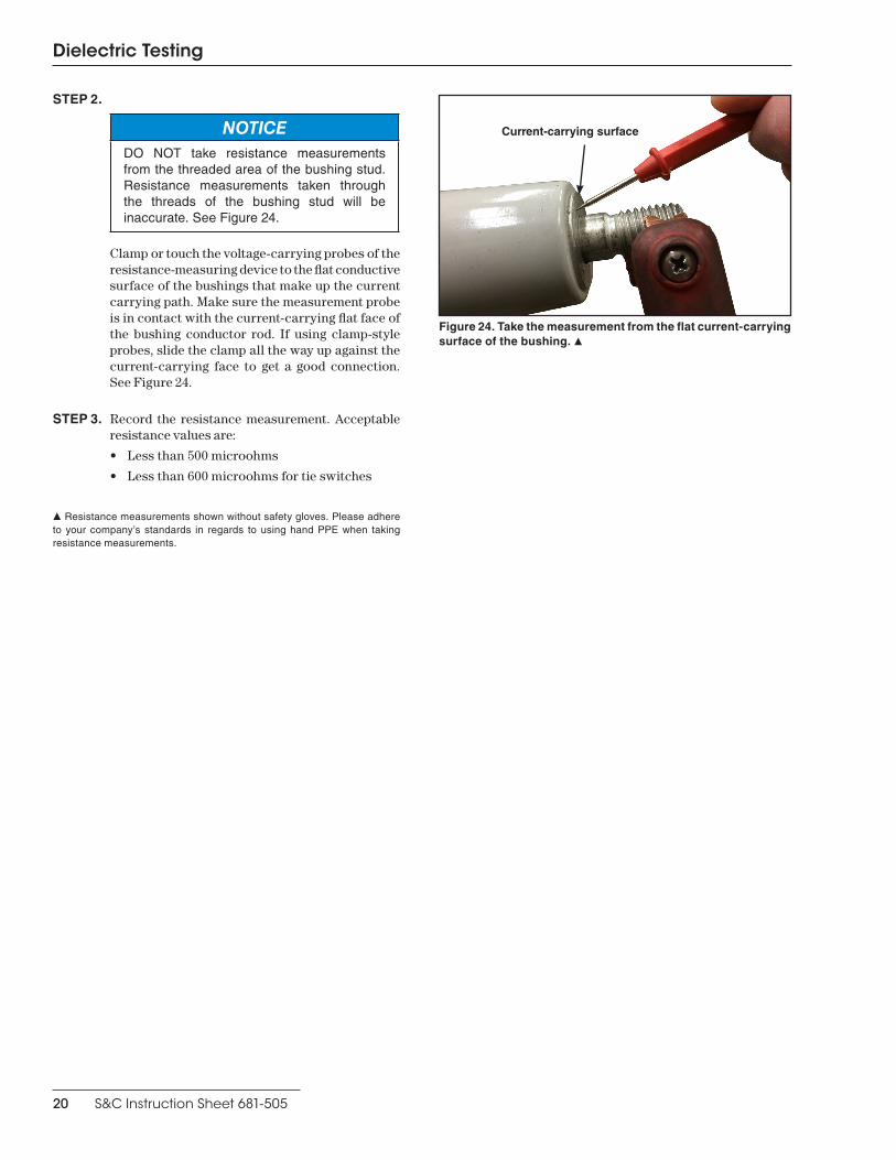
NOTICEDO NOT take resistance measurements from the threaded area of the bushing stud . Resistance measurements taken through the threads of the bushing stud will be inaccurate . See Figure 24 .
Clamp or touch the voltage-carrying probes of the resistance-measuring device to the flat conductive surface of the bushings that make up the current carrying path. Make sure the measurement probe is in contact with the current-carrying flat face of the bushing conductor rod. If using clamp-style probes, slide the clamp all the way up against the current-carrying face to get a good connection. See Figure 24.
STEP 3. Record the resistance measurement. Acceptable resistance values are:
• Less than 500 microohms
• Less than 600 microohms for tie switches
▲ Resistance measurements shown without safety gloves . Please adhere to your company’s standards in regards to using hand PPE when taking resistance measurements .
Figure 24. Take the measurement from the flat current-carrying surface of the bushing. ▲
Current-carrying surface