installation & operation manual - · pdf fileinstallation & operation manual ......
TRANSCRIPT

Installation & Operation Manual
This IOM is for the following ProMation Engineering Products:
PAO-CCW-24A2S4PAO-CCW-24D2S4

From the Spring CCW position (UNLOADED), power is connected to terminals. While power is present, the actuator will respond to drive control signals depending on the model chosen.
• A 2 position unit will drive until it reaches its LOADED position (opposite the spring return direction).
• A Proportional control unit will follow an analog control signal for positioning and will HOLD until a modifi ed control signal is received.
• In each of these models a motor brake unit is utilized to HOLD the actuator in position until commanded to move OR a loss of supply voltage.
If power is lost or removed at any time, the brake is released and the mechanical spring mechanism returns the actuator to its UNLOADED position. Once the spring mechanism has been released, the actuator will not drive under power again until:
a) The unit has reached its UNLOADED position ANDb) Power has been restored to the actuator ANDc) Initial Power Startup delay of several seconds has elapsed.
If equipped with a manual override, while the actuator is UNLOADED the manual handwheel may be employed to position the actuator anywhere between the UNLOADED and LOADED position, and the actuator will HOLD in that position indefi nitely, regardless of whether power is applied.
• The manual handwheel must return the actuator to its UNLOADED position BEFORE electrical operation of the actuator will be possible. This is a safety feature.
• If the actuator has been driven electrically to its LOADED position, the manual handwheel cannot be used to drive the actuator back to its UNLOADED position. This safety feature prevents the unexpected release of stored spring energy.
• Remote indication of actuator status can be accomplished by utilizing built-in auxiliary switches. After power has been restored these dry-contact form C switches will show when an actuator has been overridden, indicating the actuator will NOT operate under control again until it has been manually returned to the UNLOADED position (explained above).
Spring Return Theory of Operation

FM16_PA
DO
CC
W 24 2S
4 Ver H 040816
Page 1 of 12 PAO CCW HV 2S4 Series
Field ManualPAO-CCW HV 2S4 SeriesCCW Spring Return w/ Manual Override
ISO5211 F07 8P17
Table of Contentsii . . . . . . . . . . . . . . . . . . . Spring Return Theory of Operation2 . . . . . . . . . . . . . . . . . . . Product Specifications3 . . . . . . . . . . . . . . . . . . . Shipping and Handling3 . . . . . . . . . . . . . . . . . . . Product Mounting and Setup3 . . . . . . . . . . . . . . . . . . . Installation Notes4 . . . . . . . . . . . . . . . . . . . Wiring Diagram5 . . . . . . . . . . . . . . . . . . . Product Mounting and Setup5 . . . . . . . . . . . . . . . . . . . Adjusting Mechanical End-Stop CCW Position (UNLOADED)6 . . . . . . . . . . . . . . . . . . . Adjusting Cam for CCW Position (UNLOADED)6 . . . . . . . . . . . . . . . . . . . Adjusting Cam for CW Position (LOADED)7 . . . . . . . . . . . . . . . . . . . Adjusting the actuator Auxiliary Switches8 . . . . . . . . . . . . . . . . . . . Mechanical Data9 . . . . . . . . . . . . . . . . . . . Mechanical Data10 . . . . . . . . . . . . . . . . . . Commissioning11 . . . . . . . . . . . . . . . . . . Troubleshooting12 . . . . . . . . . . . . . . . . . . Spring Return Manual Override Orientation -CCW
FM16
_PA
DO
CC
W 2
4 2S
4 Ve
r H 0
4081
6
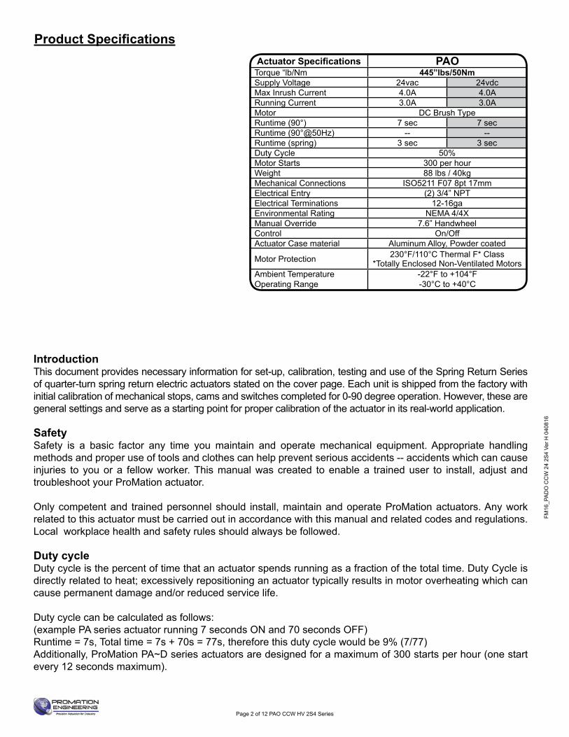
IntroductionThis document provides necessary information for set-up, calibration, testing and use of the Spring Return Series of quarter-turn spring return electric actuators stated on the cover page. Each unit is shipped from the factory with initial calibration of mechanical stops, cams and switches completed for 0-90 degree operation. However, these are general settings and serve as a starting point for proper calibration of the actuator in its real-world application.
SafetySafety is a basic factor any time you maintain and operate mechanical equipment. Appropriate handling methods and proper use of tools and clothes can help prevent serious accidents -- accidents which can cause injuries to you or a fellow worker. This manual was created to enable a trained user to install, adjust and troubleshoot your ProMation actuator.
Only competent and trained personnel should install, maintain and operate ProMation actuators. Any work related to this actuator must be carried out in accordance with this manual and related codes and regulations. Local workplace health and safety rules should always be followed.
Duty cycle Duty cycle is the percent of time that an actuator spends running as a fraction of the total time. Duty Cycle is directly related to heat; excessively repositioning an actuator typically results in motor overheating which can cause permanent damage and/or reduced service life.
Duty cycle can be calculated as follows: (example PA series actuator running 7 seconds ON and 70 seconds OFF)Runtime = 7s, Total time = 7s + 70s = 77s, therefore this duty cycle would be 9% (7/77)Additionally, ProMation PA~D series actuators are designed for a maximum of 300 starts per hour (one start every 12 seconds maximum).
Page 2 of 12 PAO CCW HV 2S4 Series
Actuator Specifi cations PAOTorque “lb/Nm 445”lbs/50NmSupply Voltage 24vac 24vdcMax Inrush Current 4.0A 4.0ARunning Current 3.0A 3.0AMotor DC Brush TypeRuntime (90°) 7 sec 7 secRuntime (90°@50Hz) -- --Runtime (spring) 3 sec 3 secDuty Cycle 50%Motor Starts 300 per hourWeight 88 lbs / 40kgMechanical Connections ISO5211 F07 8pt 17mmElectrical Entry (2) 3/4” NPTElectrical Terminations 12-16gaEnvironmental Rating NEMA 4/4XManual Override 7.6” HandwheelControl On/OffActuator Case material Aluminum Alloy, Powder coated
Motor Protection 230°F/110°C Thermal F* Class*Totally Enclosed Non-Ventilated Motors
Ambient Temperature Operating Range
-22°F to +104°F-30°C to +40°C
Wire Sizing ChartMAX distance between Actuator
and Supply (feet)
Actuator/Voltage
PAO24VAC
PAO24VDC
4.0A 4.0A
16 65 6514 105 10512 160 16010 273 2738 407 407
WireGage
Amps
Product Specifications

FM16_PA
DO
CC
W 24 2S
4 Ver H 040816
The actuator is shipped from the factory in its fully CCW position. The top illustration shows “CLOSE” on a Red background for CCW. The reverse is “OPEN” on a Yellow background for CW. The indicator may be removed and reinstalled if needed.
1. The actuator is shipped from the factory in its Spring CCW position (UNLOADED) position. Before mounting the actuator, make sure the MANUAL HANDWHEEL is able to free-wheel, indicating that the actuator is UNLOADED.
2. NOTE: This actuator is shipped with TEMPORARY PLUGS installed in BOTH EMT ports. These temporary plugs MUST be replaced with proper fi ttings appropriate for use in the environment to which the actuator is to be installed. Utilize DRIP LOOPS in the conduit connections to prevent condensate from entering the actuator. Power MUST be supplied to the unit immediately upon installation to keep the anti-condensate heater warm.
3. Storage: This unit should NOT be stored outside unless it is powered up and has proper conduit terminations. When this unit is NOT powered up, it should be stored in a clean, dry environment at all times.
4. This actuator has been factory calibrated to operate between 0 degrees and 90 degrees. Most quarter-turn products will not require recalibration of these settings. If any travel adjustment is necessary, please refer to pages 5-7 for instructions.
1. Fully CLOSE the valve or damper to which the actuator is to be mounted.• Keep in mind this spring CCW actuator rotates CCW (as viewed from above the unit) when the unit springs closed
(UNLOADED).2. Assemble necessary linkage components and attach the actuator to the driven device.3. Tighten mounting bolts, making sure actuator is centered on the device drive shaft. 4. Utilize the handwheel to check for unobstructed manual operation from fully CCW to fully CW positions BEFORE
applying power to the unit.5. Make the electrical connections per wiring diagram on page 4.
• Connect POWER AND CONTROL to terminals marked 1, 3, and 7.• Terminals labelled A-F are for the (adjustable) aux switches. They are dry type Form C rated 10A @ 250vac MAX.• Terminals A-C are for the CW (LOADED) position (adjustable).• Terminals D-F are for the CCW (UNLOADED) position (adjustable).
6. Do NOT apply power at this time.
• These actuators are designed to be used between a horizontal and upright position. Do NOT mount the assembly with the actuator top below a horizontal position.
• When installing conduit, use proper techniques for entry into the actuator. Use drip loops to prevent conduit condensate from entering the actuator.
• The mechanical travel stop is factory calibrated for the Spring CCW (UNLOADED) position. The stop is NOT designed to adjust the Spring CCW (UNLOADED) position by more than +/- 3 degrees.
• There is no mechanical stop for the LOADED position. Use caution when using the handwheel and make sure you do NOT rotate the actuator beyond the LOADED position. Observe the position by using the visual position indicator.
• Both NPT conduit ports MUST use proper equipment to protect the NEMA 4X integrity of the housing. • The internal heater is to be used in ALL applications. • Do NOT install the actuator outdoors or in humid environments unless it is powered up and the heater is functioning. • Use proper wire size to prevent actuator failure (see chart on page 4 for proper wire sizing).• All terminals accept 12-16AWG solid/stranded wire.
Bottom view of actuator showing the 8 point drive shaft and the ISO 5211 mounting hole pattern.
Page 3 of 12 PAO CCW HV 2S4 Series
Shipping and Handling
Product Mounting and Setup
Installation Notes

FM16
_PA
DO
CC
W 2
4 2S
4 Ve
r H 0
4081
6
Wire sizing data is provided in the table to assist in the selection of the proper wire size for these actuators using various wire sizes over distance. Please make sure to reference the correct voltage and do not exceed the indicated length of the wire run for each model.
Page 4 of 12 PAO CCW HV 2S4 Series
Actuator Specifi cations PAOTorque “lb/Nm 445”lbs/50NmSupply Voltage 24vac 24vdcMax Inrush Current 4.0A 4.0ARunning Current 3.0A 3.0AMotor DC Brush TypeRuntime (90°) 7 sec 7 secRuntime (90°@50Hz) -- --Runtime (spring) 3 sec 3 secDuty Cycle 50%Motor Starts 300 per hourWeight 88 lbs / 40kgMechanical Connections ISO5211 F07 8pt 17mmElectrical Entry (2) 3/4” NPTElectrical Terminations 12-16gaEnvironmental Rating NEMA 4/4XManual Override 7.6” HandwheelControl On/OffActuator Case material Aluminum Alloy, Powder coated
Motor Protection 230°F/110°C Thermal F* Class*Totally Enclosed Non-Ventilated Motors
Ambient Temperature Operating Range
-22°F to +104°F-30°C to +40°C
Wire Sizing ChartMAX distance between Actuator
and Supply (feet)
Actuator/Voltage
PAO24VAC
PAO24VDC
4.0A 4.0A
16 65 6514 105 10512 160 16010 273 2738 407 407
WireGage
Amps
On/Off Control
6
5
4
3
1
GND Screw
7
FEDCBA
-5° 0° 5° 85° 90° 95°
COM SW4
COM SW3
SP
RIN
G R
TN
(FU
LL
CC
W)
LO
AD
SP
RIN
G(F
UL
L C
W)
OPEN showing in indicatorwindow = FULLY LOADED (CW)
CLOSED showing in indicatorwindow = FULL SPRING RTN (CCW)
PA/PAO-CCW-24A or D2S4Use For:
WD
-85
0-A
AB
01
FIE
LD
WIR
ING
NEU
DRV
HOT
Actuator ships in the fullyUNLOADED (CCW) position!
BLU16 J1
RED16
24VDCBrake
250V 6.3A 5x20 FB SA
17
6H
-24
40
8-3
02
60
WHT164 3 2 1
LD3
LD4
LD1
LD2
J2
J3
LED1 - Power
LED3 - Fully OPENPosition
LED 2 - Driving inthe LOADDirection.
LED 4 - In SpringReturn andRestart Delay afterPower Trip.
U2
BLU22 NON POLARIZED
WHT22 - NOT POLARIZEDWHT
MTHERMALSWITCHRed
24VDC DRIVEMOTOR
Blk
Fe
rrit
e B
ea
d
0° - 85° *
85° - 90° *
COM *
F
E
D
C
B
A
LINE IN
* CONNECTIONSOPTIONAL
AS3
AS4
AUXILIARYSWITCH
(STANDARD)
AUXILIARYSWITCH
(STANDARD)
0° - 5° *
5° - 90° *
COM *
RED
BLU
GRY
WHT
BRN
BLK
NH
AOC
ANO
AOP
ACC
ANC
ACL
INT
ER
NA
L A
CT
UA
TO
RW
IRIN
G
COM
15W 120ΩHEATER
(on Riser)
COM
+-
24VAC 24VDC
FIELDCONTROL
DEVICE
GND
LOAD
+35A
V-
V+
AC2
AC1Blu16
Blu16
Red16
Blk16
AC Only
Red16
Blu16
DC Only(Jumpers)
-
A
GRY22 NON POLARIZED
LS1
LS2
AS3
AS4
Switch StackDetail
GRN
RED
GRN
RED
TO J1
TO J3BLU22
GRY22
NC NO COM
NC NO COM
NC NO COM
NC NO COM
LS1
COM NC
NO
GRN CAM
LS2
COM NC
NO
RED CAM
NO
NC
NO
NC
Wiring Diagram
FM16_PA
DO
CC
W 24 2S
4 Ver H 040816
Page 5 of 12 PAO CCW HV 2S4 Series
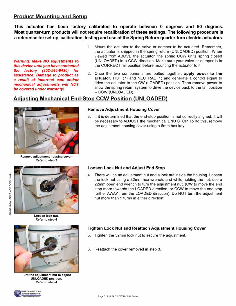
Remove adjustment housing cover.Refer to step 3
Loosen lock nut. Refer to step 4
Turn the adjustment nut to adjust UNLOADED position.
Refer to step 4
This actuator has been factory calibrated to operate between 0 degrees and 90 degrees. Most quarter-turn products will not require recalibration of these settings. The following procedure is a reference for set-up, calibration, testing and use of the Spring Return quarter-turn electric actuators.
Warning: Make NO adjustments to this device until you have contacted the factory (352-544-8436) for assistance. Damage to product as a result of incorrect cam and/or mechanical adjustments will NOT be covered under warranty!
1. Mount the actuator to the valve or damper to be actuated. Remember, the actuator is shipped in the spring return (UNLOADED) position. When viewed from ABOVE the actuator, the spring CCW units spring closed (UNLOADED) in a CCW direction. Make sure your valve or damper is in the CORRECT fail position before mounting the actuator to it.
2. Once the two components are bolted together, apply power to the actuator, HOT (7) and NEUTRAL (1) and generate a control signal to drive the actuator to the CW (LOADED) position. Then remove power to allow the spring return system to drive the device back to the fail position -- CCW (UNLOADED).
Remove Adjustment Housing Cover3. If it is determined that the end-stop position is not correctly aligned, it will
be necessary to ADJUST the mechanical END STOP. To do this, remove the adjustment housing cover using a 6mm hex key.
Loosen Lock Nut and Adjust End Stop4. There will be an adjustment nut and a lock nut inside the housing. Loosen
the lock nut using a 32mm hex wrench, and while holding the nut, use a 22mm open end wrench to turn the adjustment nut. (CW to move the end stop more towards the LOADED direction, or CCW to move the end stop further AWAY from the LOADED direction). Do NOT turn the adjustment nut more than 5 turns in either direction!
Tighten Lock Nut and Reattach Adjustment Housing Cover5. Tighten the 32mm lock nut to secure the adjustment.
6. Reattach the cover removed in step 3.
Product Mounting and Setup
Adjusting Mechanical End-Stop CCW Position (UNLOADED)
FM16
_PA
DO
CC
W 2
4 2S
4 Ve
r H 0
4081
6
Page 6 of 12 PAO CCW HV 2S4 Series
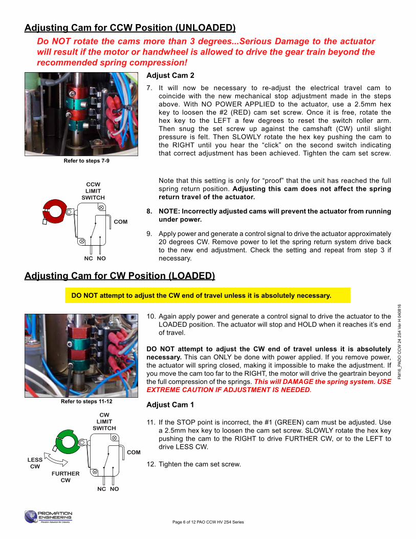
Refer to steps 7-9
Refer to steps 11-12
DO NOT attempt to adjust the CW end of travel unless it is absolutely necessary.
Note that this setting is only for “proof” that the unit has reached the full spring return position. Adjusting this cam does not affect the spring return travel of the actuator.
8. NOTE: Incorrectly adjusted cams will prevent the actuator from running under power.
9. Apply power and generate a control signal to drive the actuator approximately 20 degrees CW. Remove power to let the spring return system drive back to the new end adjustment. Check the setting and repeat from step 3 if necessary.
Adjust Cam 27. It will now be necessary to re-adjust the electrical travel cam to
coincide with the new mechanical stop adjustment made in the steps above. With NO POWER APPLIED to the actuator, use a 2.5mm hex key to loosen the #2 (RED) cam set screw. Once it is free, rotate the hex key to the LEFT a few degrees to reset the switch roller arm. Then snug the set screw up against the camshaft (CW) until slight pressure is felt. Then SLOWLY rotate the hex key pushing the cam to the RIGHT until you hear the “click” on the second switch indicating that correct adjustment has been achieved. Tighten the cam set screw.
Do NOT rotate the cams more than 3 degrees...Serious Damage to the actuator will result if the motor or handwheel is allowed to drive the gear train beyond the recommended spring compression!
10. Again apply power and generate a control signal to drive the actuator to the LOADED position. The actuator will stop and HOLD when it reaches it’s end of travel.
DO NOT attempt to adjust the CW end of travel unless it is absolutely necessary. This can ONLY be done with power applied. If you remove power, the actuator will spring closed, making it impossible to make the adjustment. If you move the cam too far to the RIGHT, the motor will drive the geartrain beyond the full compression of the springs. This will DAMAGE the spring system. USE EXTREME CAUTION IF ADJUSTMENT IS NEEDED.
Adjust Cam 1
11. If the STOP point is incorrect, the #1 (GREEN) cam must be adjusted. Use a 2.5mm hex key to loosen the cam set screw. SLOWLY rotate the hex key pushing the cam to the RIGHT to drive FURTHER CW, or to the LEFT todrive LESS CW.
12. Tighten the cam set screw.
COM
NONC
COM
NONC
LESSCW
FURTHERCW
CCWLIMIT
SWITCH
CWLIMIT
SWITCH
COM
NONC
COM
NONC
LESSCW
FURTHERCW
CCWLIMIT
SWITCH
CWLIMIT
SWITCH
DO NOT attempt to adjust the CW end of travel unless it is absolutely necessary.
Adjusting Cam for CCW Position (UNLOADED)
Adjusting Cam for CW Position (LOADED)
FM16_PA
DO
CC
W 24 2S
4 Ver H 040816
Page 7 of 12 PAO CCW HV 2S4 Series
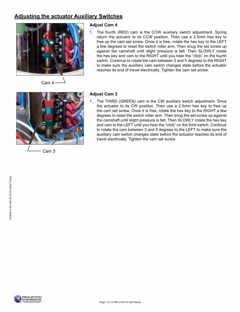
Adjust Cam 4 1. The fourth (RED) cam is the CCW auxiliary switch adjustment. Spring
return the actuator to its CCW position. Then use a 2.5mm hex key to free up the cam set screw. Once it is free, rotate the hex key to the LEFT a few degrees to reset the switch roller arm. Then snug the set screw up against the camshaft until slight pressure is felt. Then SLOWLY rotate the hex key and cam to the RIGHT until you hear the “click” on the fourth switch. Continue to rotate the cam between 3 and 5 degrees to the RIGHT to make sure the auxiliary cam switch changes state before the actuator reaches its end of travel electrically. Tighten the cam set screw.
Adjust Cam 3 1. The THIRD (GREEN) cam is the CW auxiliary switch adjustment. Drive
the actuator to its CW position. Then use a 2.5mm hex key to free up the cam set screw. Once it is free, rotate the hex key to the RIGHT a few degrees to reset the switch roller arm. Then snug the set screw up against the camshaft until slight pressure is felt. Then SLOWLY rotate the hex key and cam to the LEFT until you hear the “click” on the third switch. Continue to rotate the cam between 3 and 5 degrees to the LEFT to make sure the auxiliary cam switch changes state before the actuator reaches its end of travel electrically. Tighten the cam set screw.
Cam 4
Cam 3
Adjusting the actuator Auxiliary Switches
FM16
_PA
DO
CC
W 2
4 2S
4 Ve
r H 0
4081
6
Page 8 of 12 PAO CCW HV 2S4 Series
1
1
2
2
A A
B B
Drawn By
Finish
Promation Engineering Inc.16138 Flight Path Drive
Brooksville, Fl 34604Phone: 352-544-8436Fax: 352-544-8439
This Document is the property of ProMation Engineering,Inc. Distribution of this document without the written
consent of the owner is Strictly forbidden. Failure to comply will incur a liability for Damages.
Checked By4/8/2015
PAO-CCW Dim Data Rev.C
NO SCALE Sheet Number: 1
Material
ProMation Engineering, Inc.KHL
KHL
11/14/2014
PAO_CCW F07 8P17 DimData.idw
Created:
Last Checked:
Part No.
Dwg. Name
Dimensional Data for PAO-CCW Spring Return Actuators
Engineering Change NoticeChange Date Description Name
11.14.2014 New Document KHL
04.08.2015 Added Isometric view of Drive Coupling and "Depth" tag for clarity KHL
04.07.2016 Added PA height front view TJM
REVA
B
C
D
E
F
Dimensional Tolerances (Unless Otherwise Noted):X ± 2.5mm [X.X ± .1]
X.X ± .3mm [X.XX ± .01"]X.XX ± .13mm [X.XXX ± .005"]
ALL TOLERANCE FEATURES IN mm
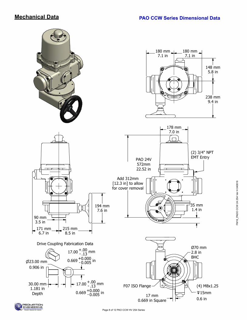
Drive Coupling Fabrication Data
17.00 - .13.00+ mm
0.669 - 0.0050.000+ in
17.00 - .13.00+ mm
0.669 - 0.0050.000+ in
23.00 mm0.906 in
30.00 mm1.181 inDepth
PAO 24V572mm22.52 in
171 mm6.7 in
215 mm8.5 in
194 mm7.6 in
180 mm7.1 in
180 mm7.1 in
148 mm5.8 in
238 mm9.4 in
178 mm7.0 in
534 mm21.0 in
Add 312mm[12.3 in] to allowfor cover removal
90 mm3.5 in
35 mm1.4 in
Ø70 mm2.8 inBHC
(4) M8x1.25
15mm0.6 in
17 mm0.669 in Square
F07 ISO Flange
(2) 3/4" NPTEMT Entry
PAO CCW Series Dimensional DataMechanical Data
FM16_PA
DO
CC
W 24 2S
4 Ver H 040816
Page 9 of 12 PAO CCW HV 2S4 Series
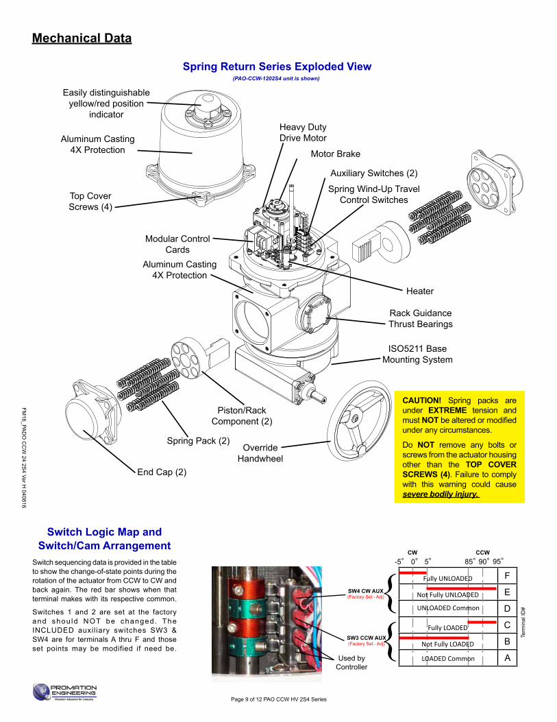
CAUTION! Spring packs are under EXTREME tension and must NOT be altered or modifi ed under any circumstances.
Do NOT remove any bolts or screws from the actuator housing other than the TOP COVER SCREWS (4). Failure to comply with this warning could cause severe bodily injury.
Easily distinguishable yellow/red position
indicator
Piston/RackComponent (2)
OverrideHandwheel
Heavy DutyDrive Motor
Modular ControlCards
Aluminum Casting4X Protection
Top Cover Screws (4)
Aluminum Casting4X Protection
Spring Pack (2)
ISO5211 Base Mounting System
Motor Brake
Spring Wind-Up Travel Control Switches
Heater
Rack GuidanceThrust Bearings
Auxiliary Switches (2)
End Cap (2)
(PAO-CCW-1202S4 unit is shown)
Spring Return Series Exploded View
Switch Logic Map and Switch/Cam Arrangement
Switch sequencing data is provided in the table to show the change-of-state points during the rotation of the actuator from CCW to CW and back again. The red bar shows when that terminal makes with its respective common.
Switches 1 and 2 are set at the factory and shou ld NOT be changed. The INCLUDED auxil iary switches SW3 & SW4 are for terminals A thru F and those set points may be modified if need be.
SW3 CCW AUX(Factory Set - Adj)
SW4 CW AUX(Factory Set - Adj)
Used by
Controller
Term
inal
ID#
F
E
D
C
B
A
-5° 0°CW CCW
85°5° 90° 95°
LOADED Common
UNLOADED Common
Not Fully UNLOADED
Fully LOADED
Not Fully LOADED
Fully UNLOADED
Mechanical Data

FM16
_PA
DO
CC
W 2
4 2S
4 Ve
r H 0
4081
6
After completing all mounting and wiring procedures and main power is available, it is now possible to commission the actuator.
1. For units with a handwheel, utilize the handwheel to rotate the actuator and damper, valve or other connected device through its full travel from UNLOADED to LOADED and back again to check for any possible interference. Do NOT utilize any mechanical advantage devices to rotate the handwheel (pipes, wrenches, extension bars, etc.). The spring will drive the device CCW, following the rotation of the handwheel.
2. Apply correct power to the unit.3. Measure correct power on terminals 7 & 1 on the switch board.4. Command the fi eld device to generate a signal to drive the actuator towards the LOADED position.
The actuator rotates in a CW direction (as viewed from above).5. Actuator will stop when it reaches it’s LOADED position.6. Command the fi eld device to generate a signal to drive the actuator towards the UNLOADED position.
The actuator spring returns in a CCW direction (as viewed from above).7. Actuator will stop when it reaches it’s UNLOADED position and the handwheel (if equipped) is not
blocking the full spring return positioning.8. Actuator is now commissioned and operational.
Page 10 of 12 PAO CCW HV 2S4 Series
Commissioning

FM16_PA
DO
CC
W 24 2S
4 Ver H 040816
Page 11 of 12 PAO CCW HV 2S4 Series
#2 Cam Positions: UNLOADEDIncorrect
#2 Cam switch lever.Press towards black switch body to hear
“click”. The switch will also click as it releases.
#2 Cam switch. At actuator UNLOADED position you
should be able to depress the #2 switch LEVER and hear it “click”.
Lower RED cam position showing the switch roller riding high on the cam lobe. In this position, you cannot press on the switch roller lever and hear the switch “click”. In this position, the actuator will NOT restart after a power failure.
Lower RED cam position showing the switch roller sitting in the CORRECT position at the full spring return end of travel. With the switch roller positioned as shown, the switch will “click” when the switch roller lever is pressed and the controller WILL restart after a power failure.
Correct
101714 We began using the round red cams in products/IOMs.101714 We began using the round red cams in products/IOMs.
If no “click” is heard and the actuator is in fact UNLOADED, the cam is in the wrong position and is keeping the switch from changing state.Use a 2.5mm hex key and rotate the RED #2 cam SLIGHTLY CCW until “click” is heard. Lightly resecure the cam in position to test. Secure fully after testing.
Spring Return Actuator UNLOADED position and not restarting on power-up
Troubleshooting
FM16
_PA
DO
CC
W 2
4 2S
4 Ve
r H 0
4081
6
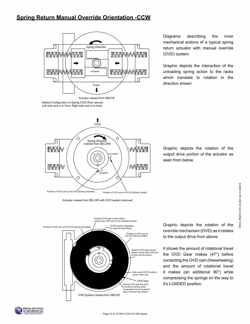
Spring Direction
Default Configuration is Spring CCW (from above).Left side rack is in front, Right side rack is in back.
Actuator viewed from BELOW with OVD system removed
Front
Front
Position of OVD cam at full CCW (Spring Unloaded) Position of OVD cam at full CW (Spring Loaded)
OVD System viewed from ABOVE
Position of OVD cam at full CCW (Spring Unloaded)
Position of OVD cam at
Actuator viewed from ABOVE
Fully wound STOP position set by motor cam
Front
Distance OVD gear travels beforecontact with OVD cam at full unloaded position
Distance OVD gear travelsbefore contact with OVD camat fully wound position
STOP position adjustableby side mounted limiter
full CW (Spring Loaded)
Manual OVD past this pointis limited by spring pistoncompression travel (outward)stop in the end cap casting.
Spring Direction(viewed from BELOW)
Loading
spring
Unloaded
Unloaded
Loaded
Loaded
Unloaded
Diagrams describing the inner mechanical actions of a typical spring return actuator with manual override (OVD) system.
Graphic depicts the interaction of the unloading spring action to the racks which translate to rotation in the direction shown.
Graphic depicts the rotation of the output drive portion of the actuator as seen from below.
Graphic depicts the rotation of the override mechanism (OVD) as it relates to the output drive from above.
It shows the amount of rotational travel the OVD Gear makes (47°) before contacting the OVD cam (freewheeling)and the amount of rotational travel it makes (an additional 90°) while compressing the springs on the way to it’s LOADED position.
OVD Gear
Page 12 of 12 PAO CCW HV 2S4 Series
Spring Return Manual Override Orientation -CCW

ProMation Engineering, Inc . 16138 Flight Path Drive Brooksville, FL 34604 Phone (352) 544-8436 Fax (352) 544-8439 www .promationei .com

IOM
Tem
plat
e M
aste
r.ind
d
Industrial ApplicationsProMation Engineering actuators have been installed to operate process controls such as butterfl y valves, ball valves, high performance valves, plug valves, gate valves and dampers, in a broad range of demanding industrial applications.
Power Generation
Water Processes Mining Oil and Gas Agriculture Chemicals
16138 Flight Path Drive Brooksville, FL 34604
Phone (352) 544-8436 Fax (352) 544-8439email: sales@promationei .com
Complete Support
Full Documentation We offer complete wiring diagrams, fi eld installation manuals and set up documentation for all our products, both in printed and digital form. We regularly host customized educational webinars for our customers.
RapidQuoteMost quotes and estimates are generated within hours of the request.
ProMation Engineering Services ProMation Engineering can provide design and technical services for OEM’s, projects with customized requirements and specialized operations.
ProMation Engineering is committed to providing superior customer support for your sales, project management and installation teams. Contact us today.
ProMation Engineering follows a policy of continual product updates and enhancements. Our website is the best place to obtain the latest product documentation, including the wiring diagrams for these
controllers. Visit us at www.promationei.com or use the code to link to the site.
Use your smart phone barcode scanner app here.