installation & operating guide - rv 7/arv7-a.com/manuals/manual l113v9.pdf · 3 drive gear...
TRANSCRIPT

Product Documentation
Installation & Operating Guide
V L113.9

Guide Applicable to E-MAG Ignition Models
E-113 and P-113 Ignitions on Lycoming 4 Cylinder Engines (Serial #s 393 or greater - subject to revision).
Experimental Aircraft Only
E-Mag ignitions are not (currently) certified and are not approved for installation on certified aircraft.
Warranty Your E-MAG electronic ignition is warranted for one (1) year from the date of purchase. Any unit returned must first receive a return authorization number prior to shipping (postage paid). E-MAG will repair or replace ignition modules within the warranty period that, in E-MAG’s sole opinion, have not been subjected to abuse or any attempted field repairs. Note: This represents a reduction in our warranty compared to earlier releases. This has been done in response to the unexpected impact our previous (3 year) warranty was having on our banking and credit card merchant account relationships. In lieu of a 3 year “warranty” we have instituted an extremely lenient “policy” of service and support for our products.
Caution The aircraft operator has the SOLE responsibility of determining how to appropriately and safely control engine operation. Nothing stated by E-MAG, its employees, owners, agents or affiliates should be construed as overriding or invalidating the engine manufacturer’s instructions (including lean operation warnings).
Patents Pending
Copyright © E-MAG Ignitions, All rights reserved. 649 Boling Ranch Road
Azle, Texas 76020 Phone (817) 448 0555
1
Table of Contents
OVERVIEW .......................................................................................................................................................................................................2
DRIVE GEAR ....................................................................................................................................................................................................3
CONTROLS ......................................................................................................................................................................................................4
SPARK PLUGS & HARNESS ..........................................................................................................................................................................5
INSTALLATION AND TIMING..........................................................................................................................................................................9
OPERATING NOTES......................................................................................................................................................................................13
WIRING DIAGRAM.........................................................................................................................................................................................16
CURRENT DRAW...........................................................................................................................................................................................17
2
Using This Manual Your E-MAG is designed to make installation as straightforward and as simple as possible. To further assist you, this manual includes a variety of comments and tips. These tips are shown in italics and in dark blue for easier identification and printing.
Please note, the term “E-MAG” shall apply to both E-MAG and P-MAG models, unless specifically stated otherwise.
Installation
Overview Installing your E-MAG ignition will require you to:
1. Install the drive gear on your ignition.
2. Install wiring:
a. Attach three (four if you use the tack) leads to the Control Plug.
b. Spark plugs and the spark plug harness
c. MAP (manifold pressure) sensor tube
3. Install your E-MAG ignition on the engine, set the timing, and select the maximum timing advance.
CAUTION: Do NOT strike or apply significant inward force to the ignition shaft. Doing so could damage or misalign the position sensor.
CAUTION: Operating the ignition without all connections – 1) power, 2) ground, 3) p-lead, 4) plug wires with plugs (and all plugs grounded) can result in damage to the ignition and/or cause an electrical shock to the installer. Please resist the temptation to do a quick (incomplete) hook up so you can watch the ignition spark or make the LED light up. Firing the ignition without all connections could damage the unit, and void your warranty.

3
Drive Gear E-MAG ignitions are indexed to the engine through a drive gear. The drive gear from a non-impulse magneto can be recovered and, if in good condition, be reinstalled on your E-MAG. Gears from an impulse magneto are different, and cannot be reused.
To recover the drive gear from an existing magneto:
1. Remove the cotter key, castle nut, and washers. A strap wrench is helpful while removing (or re-installing) the castle nut from the ignition shaft.
2. Remove the drive gear from the magneto shaft. A gear puller will be necessary to remove the gear without damaging it, or the magneto. NEVER strike the magneto, the gear, or the shaft in order to remove or install the gear.
3. Install the drive gear on the E-MAG shaft using the woodruff key, washer(s), castle nut, and cotter key provided. Your kit includes three washers (one thick and two thin). At least one washer should always be used. Additional washers can be used to align the hole for the cotter key with the castle nut when tightened. Make certain the cotter key ends lay flat and do not extend past the open face of the gear. The back wall of the accessory case will be close to the face of the drive gear, and you don’t want any protrusions that could make contact and wear against the back.
Woodruff Key installed in shaft
4
Anchor Screws
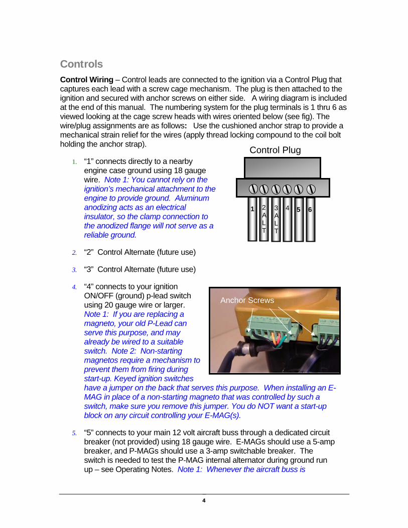
Controls Control Wiring – Control leads are connected to the ignition via a Control Plug that captures each lead with a screw cage mechanism. The plug is then attached to the ignition and secured with anchor screws on either side. A wiring diagram is included at the end of this manual. The numbering system for the plug terminals is 1 thru 6 as viewed looking at the cage screw heads with wires oriented below (see fig). The wire/plug assignments are as follows: Use the cushioned anchor strap to provide a mechanical strain relief for the wires (apply thread locking compound to the coil bolt holding the anchor strap).
1. “1” connects directly to a nearby engine case ground using 18 gauge wire. Note 1: You cannot rely on the ignition’s mechanical attachment to the engine to provide ground. Aluminum anodizing acts as an electrical insulator, so the clamp connection to the anodized flange will not serve as a reliable ground.
2. “2” Control Alternate (future use)
3. “3” Control Alternate (future use)
4. “4” connects to your ignition ON/OFF (ground) p-lead switch using 20 gauge wire or larger. Note 1: If you are replacing a magneto, your old P-Lead can serve this purpose, and may already be wired to a suitable switch. Note 2: Non-starting magnetos require a mechanism to prevent them from firing during start-up. Keyed ignition switches have a jumper on the back that serves this purpose. When installing an E-MAG in place of a non-starting magneto that was controlled by such a switch, make sure you remove this jumper. You do NOT want a start-up block on any circuit controlling your E-MAG(s).
5. “5” connects to your main 12 volt aircraft buss through a dedicated circuit breaker (not provided) using 18 gauge wire. E-MAGs should use a 5-amp breaker, and P-MAGs should use a 3-amp switchable breaker. The switch is needed to test the P-MAG internal alternator during ground run up – see Operating Notes. Note 1: Whenever the aircraft buss is
Tack
1
Control Plug
4 5 6 3ALT
2ALT
5
MAP hose connection
LED
Cylinders 1 & 2
Cylinders 3 & 4
LED Indicator
powered up, the ignition is “awake”. It draws a small amount of current even when not firing the plugs. Use the main buss switch (or breakers if necessary) to power down the ignitions when not in use
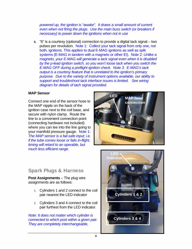
6. ”6” is a courtesy (optional) connection to provide a digital tack signal – two pulses per revolution. Note 1: Collect your tack signal from only one, not both, ignitions. This applies to dual E-MAG ignitions as well as split systems (E-MAG in tandem with a magneto or other EI). Note 2: Unlike a magneto, your E-MAG will generate a tack signal even when it is disabled by the p-lead ignition switch, so you won’t loose tack when you switch the E-MAG OFF during a preflight ignition check. Note 3: E-MAG’s tack output is a courtesy feature that is unrelated to the ignition’s primary purpose. Due to the variety of instrument options available, our ability to support and troubleshoot tack interface issues is limited. See wiring diagram for details of tach signal provided.
MAP Sensor
Connect one end of the sensor hose to the MAP nipple on the back of the ignition case next to the coil base, and secure with nylon clamp. Route the line to a convenient connection point (connecting hardware not included) where you can tee into the line going to your manifold pressure gauge. Note 1: The MAP sensor is a fail-safe input; i.e. if the tube comes loose or fails in-flight, timing will retard to an operable, but much less efficient range.
Spark Plugs & Harness Post Assignments – The plug wire assignments are as follows:
1. Cylinders 1 and 2 connect to the coil pair nearest the LED indicator
2. Cylinders 3 and 4 connect to the coil pair furthest from the LED indicator.
Note: It does not matter which cylinder is connected to which post within a given pair. They are completely interchangeable,
6
which can be convenient to help fine tune the wire lengths.
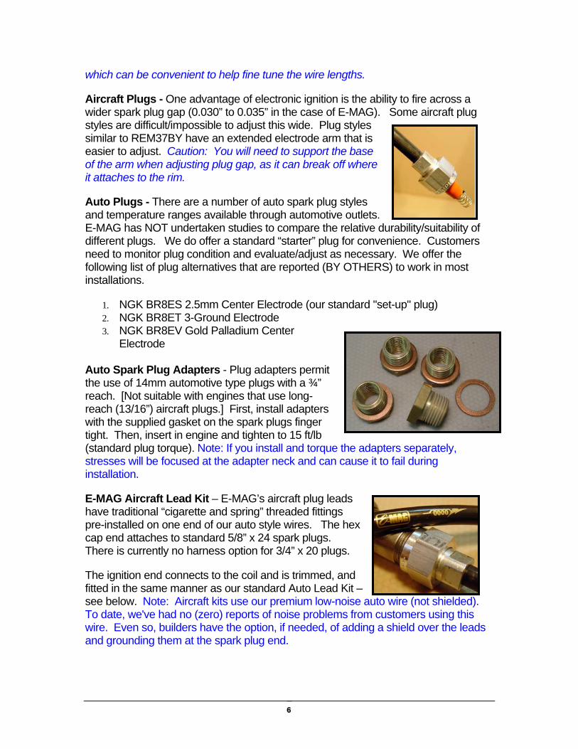
Aircraft Plugs - One advantage of electronic ignition is the ability to fire across a wider spark plug gap (0.030” to 0.035” in the case of E-MAG). Some aircraft plug styles are difficult/impossible to adjust this wide. Plug styles similar to REM37BY have an extended electrode arm that is easier to adjust. Caution: You will need to support the base of the arm when adjusting plug gap, as it can break off where it attaches to the rim.
Auto Plugs - There are a number of auto spark plug styles and temperature ranges available through automotive outlets. E-MAG has NOT undertaken studies to compare the relative durability/suitability of different plugs. We do offer a standard “starter” plug for convenience. Customers need to monitor plug condition and evaluate/adjust as necessary. We offer the following list of plug alternatives that are reported (BY OTHERS) to work in most installations.
1. NGK BR8ES 2.5mm Center Electrode (our standard "set-up" plug) 2. NGK BR8ET 3-Ground Electrode 3. NGK BR8EV Gold Palladium Center
Electrode
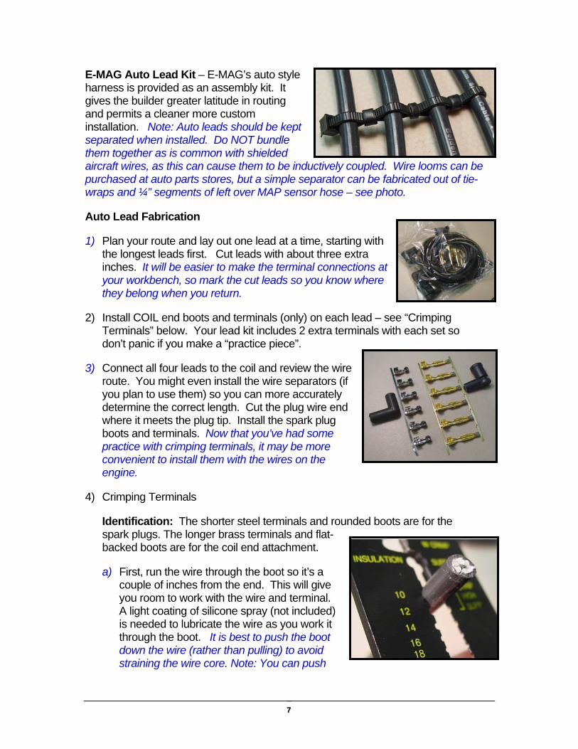
Auto Spark Plug Adapters - Plug adapters permit the use of 14mm automotive type plugs with a ¾” reach. [Not suitable with engines that use long-reach (13/16”) aircraft plugs.] First, install adapters with the supplied gasket on the spark plugs finger tight. Then, insert in engine and tighten to 15 ft/lb (standard plug torque). Note: If you install and torque the adapters separately, stresses will be focused at the adapter neck and can cause it to fail during installation.
E-MAG Aircraft Lead Kit – E-MAG’s aircraft plug leads have traditional “cigarette and spring” threaded fittings pre-installed on one end of our auto style wires. The hex cap end attaches to standard 5/8” x 24 spark plugs. There is currently no harness option for 3/4” x 20 plugs.
The ignition end connects to the coil and is trimmed, and fitted in the same manner as our standard Auto Lead Kit – see below. Note: Aircraft kits use our premium low-noise auto wire (not shielded). To date, we've had no (zero) reports of noise problems from customers using this wire. Even so, builders have the option, if needed, of adding a shield over the leads and grounding them at the spark plug end.
7
E-MAG Auto Lead Kit – E-MAG’s auto style harness is provided as an assembly kit. It gives the builder greater latitude in routing and permits a cleaner more custom installation. Note: Auto leads should be kept separated when installed. Do NOT bundle them together as is common with shielded aircraft wires, as this can cause them to be inductively coupled. Wire looms can be purchased at auto parts stores, but a simple separator can be fabricated out of tie-wraps and ¼” segments of left over MAP sensor hose – see photo.
Auto Lead Fabrication
1) Plan your route and lay out one lead at a time, starting with the longest leads first. Cut leads with about three extra inches. It will be easier to make the terminal connections at your workbench, so mark the cut leads so you know where they belong when you return.
2) Install COIL end boots and terminals (only) on each lead – see “Crimping Terminals” below. Your lead kit includes 2 extra terminals with each set so don’t panic if you make a “practice piece”.
3) Connect all four leads to the coil and review the wire route. You might even install the wire separators (if you plan to use them) so you can more accurately determine the correct length. Cut the plug wire end where it meets the plug tip. Install the spark plug boots and terminals. Now that you’ve had some practice with crimping terminals, it may be more convenient to install them with the wires on the engine.
4) Crimping Terminals
Identification: The shorter steel terminals and rounded boots are for the spark plugs. The longer brass terminals and flat-backed boots are for the coil end attachment.
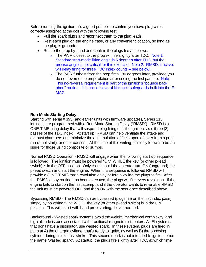
a) First, run the wire through the boot so it’s a couple of inches from the end. This will give you room to work with the wire and terminal. A light coating of silicone spray (not included) is needed to lubricate the wire as you work it through the boot. It is best to push the boot down the wire (rather than pulling) to avoid straining the wire core. Note: You can push

8
Bend coil terminal 90 degrees.
on the heel of the boot and straighten the opening so it is aligned with the wire as you push it through.
b) Use the Crimp Tool to trim 1” of shielding from the wire end. Use the largest opening on the tool stripper (position “10”) to GENTLY cut the shield. Make one cut, and then a second cut with the tool rotated 90 degrees to ensure you cut the insulation all the way around the core. You can then twist the trimmed wire shield to complete the separation. Continue twisting as you remove the shield from the core.
c) Free the terminals from their strips with wire cutters.
d) Fold the wire core back against the shield and position in the crook of the terminal ears, and “Pre-Crimp” the terminal. Pre-Crimping will snug the ears against the wire shield (for positioning) and point the tips of the ears inward just enough so they fit in the “W Crimp” slot on the tool.
e) “Final Crimp” the terminal using the “W Crimp” slot on the Crimp Tool. The ears feed into the side that has the “W” point. This way the ears will roll back toward each other and imbed themselves in the shield as the Final Crimp is formed.
Core wire is folded back.
Pre-Crimp jaws are near tool
hinge.

9
“W Crimp” Slot
Pre-Crimp Jaws
Ears Fold Inwar
Crimp Tool Close-up
f) Push (not pull) the terminal to position it inside the boot. The longer coil terminals will need to be bent 90 degrees (at the narrow section) before positioning in the boot.
Installation and Timing Note 1: If replacing an impulse magneto, you need to remove the magneto impulse spacer. Impulse magnetos are traditionally installed on the left side. The spacer is a roughly 1” spacer located between the magneto and the engine case. The studs that hold the spacer to the case will be too long for use with the E-MAG. You’ll need to replace the long studs with shorter ones, or simply use suitable length bolts (not provided).
Note 2: These Installation and Timing procedures are strictly limited to E-MAG (meaning both E-MAG and P-MAG models) ignitions ONLY. If you are installing dual E-MAGs, pull the breaker AND the coil plug (see photo below) from BOTH ignitions. Reconnect them ONLY as instructed and only for the ignition you are working with. If you have a companion ignition by another manufacturer, BE ADVISED you need to follow all safety and handling guidelines appropriate for that system – SEPARATE AND APPART from the instructions provided here for your E-MAG.
Confirm all connections to the ignition as follows, but do not install the ignition in the engine until instructed to do so:
10
Jumper for Low Advance
Coil Plug
• Control leads (12 volt, ground, ON/OFF P-lead), 1 (optional) tack lead, and possibly a jumper between terminals #2 and #3 (see below) all of which attach to the (6) position Control Plug. Insert this plug into the receptacle and secure with the anchor screws on each end.
• 3 lead coil plug to should be DISCONNECTED so the plugs cannot fire during these setup procedures. Note: While in Setup Mode (see below), the ignition is configures so the plugs will not fire. Disconnecting the coil plug(s) is simply added insurance to make sure the plugs can’t fire while you are installing and setting the timing.
• MAP Sensor tube. • Spark Plug Leads - with sparks plugs installed in the engine (or
plugs grounded to engine case).
Variable Timing Limit:
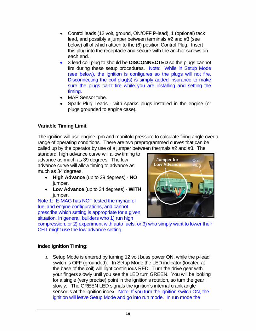
The ignition will use engine rpm and manifold pressure to calculate firing angle over a range of operating conditions. There are two preprogrammed curves that can be called up by the operator by use of a jumper between thermals #2 and #3. The standard high advance curve will allow timing to advance as much as 39 degrees. The low advance curve will allow timing to advance as much as 34 degrees.
• High Advance (up to 39 degrees) - NO jumper.
• Low Advance (up to 34 degrees) - WITH jumper.
Note 1: E-MAG has NOT tested the myriad of fuel and engine configurations, and cannot prescribe which setting is appropriate for a given situation. In general, builders who 1) run high compression, or 2) experiment with auto fuels, or 3) who simply want to lower their CHT might use the low advance setting.
Index Ignition Timing:
1. Setup Mode is entered by turning 12 volt buss power ON, while the p-lead switch is OFF (grounded). In Setup Mode the LED indicator (located at the base of the coil) will light continuous RED. Turn the drive gear with your fingers slowly until you see the LED turn GREEN. You will be looking for a single (very precise) point in the ignition’s rotation, so turn the gear slowly. The GREEN LED signals the ignition’s internal crank angle sensor is at the ignition index. Note: If you turn the ignition switch ON, the ignition will leave Setup Mode and go into run mode. In run mode the

11
plugs will fire if the coil plug is connected and the ignition sensor sees the firing position. In order to reenter Setup Mode you must turn the switch OFF and turn 12 volt power OFF. You can then apply 12 volt power WHILE the p-lead switch is OFF, per the instructions above.
2. Rotate your prop to the engine TDC (or TC) timing mark. By approaching this mark with the prop moving in the direction of normal engine rotation you can minimize play in the gears. Note 1: Be wary of old magneto timing habits. Magnetos are timed using the 25 degree (or other) BTDC marks. You will use the TDC mark ONLY. Note 2: It does not matter whether the engine is on the compression or exhaust stroke for a particular cylinder. Note 3: On some engines, “TC” is stamped on the ring gear, which aligns with a reference alignment hole on the starter. On others, a ring gear mark is lined up with the engine case seem. Consult you engine manual on how to locate TDC.
3. Without moving the drive gear, position the gasket on the E-MAG flange and install the ignition in the engine accessory case. You will engage the ignition drive gear with a gear inside the accessory case. Don’t worry if you bump the gear and lose your LED light at this point, but try to avoid moving the gear very far off the index (GREEN) position. Note: It is critical that the ignition flange face and the flange seating area of the accessory case be thoroughly cleared of ANY old gasket material or other residue. Even small amount of build up under one edge can result in the ignition being skewed, and the ignition gear engagement being too tight or too loose. For that reason, gasket sealing materials, if used at all, must be evenly and equally distributed around the flange face.
4. After the ignition is positioned in the case, install your mounting clips, washer and nut (or bolt as the case may be). Tighten only finger tight at this time.
5. Reacquire the GREEN LED indicator by slowly rotating the ignition. If you don’t have sufficient adjustment range to reacquire the GREEN LED, you can remove the ignition, rotate the gear a distance equal to one tooth width, and reinsert the ignition. This should put the index (GREEN) position within your adjustment range.
6. Once the GREEN LED is reacquired, secure the position by tightening the mounting clips.
7. When finished setting the timing for both ignitions (and only then) you can then reconnect the coil plug to the ignition.
Confirm Plug Wiring:
12
Before running the ignition, it’s a good practice to confirm you have plug wires correctly assigned at the coil with the following test:
• Pull the spark plugs and reconnect them to the plug leads. • Rest each plug on the engine case, or any convenient location, so long as
the plug is grounded. • Rotate the prop by hand and confirm the plugs fire as follows:
o The PAIR closest to the prop will fire slightly after TDC. Note 1: Standard start-mode firing angle is 5 degrees after TDC, but the precise angle is not critical for this exercise. Note 2: RMSD, if active, will delay firing for three TDC index counts – see below.
o The PAIR furthest from the prop fires 180 degrees later, provided you do not reverse the prop rotation after seeing the first pair fire. Note: This no-reversal requirement is part of the ignition’s “bounce back abort” routine. It is one of several kickback safeguards built into the E-MAG.
Run Mode Starting Delay: Starting with serial # 393 (and earlier units with firmware updates), Series 113 ignitions are programmed with a Run Mode Starting Delay (”RMSD”). RMSD is a ONE-TIME firing delay that will suspend plug firing until the ignition sees three (3) passes of the TDC index. At start up, RMSD can help ventilate the intake and exhaust chambers and minimize the accumulation of fuel vapor left over from a prior run (a hot start), or other causes. At the time of this writing, this only known to be an issue for those using composite oil sumps. Normal RMSD Operation - RMSD will engage when the following start up sequence is followed. The ignition must be powered “ON” WHILE the key (or other p-lead switch) is in the OFF position. Only then should the operator turn ON (unground) the p-lead switch and start the engine. When this sequence is followed RMSD will provide a (ONE TIME) three revolution delay before allowing the plugs to fire. After the RMSD delay routine has been executed, the plugs will fire every revolution. If the engine fails to start on the first attempt and if the operator wants to re-enable RMSD the unit must be powered OFF and then ON with the sequence described above. Bypassing RMSD - The RMSD can be bypassed (plugs fire on the first index pass) simply by powering “ON” WHILE the key (or other p-lead switch) is in the ON position. This will assist with hand prop starting, if ever needed. Background - Wasted spark systems avoid the weight, mechanical complexity, and high altitude issues associated with traditional magneto distributors. All EI systems that don’t have a distributor, use wasted spark. In these system, plugs are fired in pairs at A) the charged cylinder that’s ready to ignite, as well as B) the opposing cylinder during its exhaust stroke. This second spark is not intended to ignite, hence the name “wasted spark”. At startup, the plugs fire slightly after TDC, at which time

13
the “wasted” side will be at a period of valve overlap. [Valve overlap is when the intake and exhaust valves are open at the same time.] When starting an engine where vapor has accumulated in the “wasted” cylinder, this vapor can ignite. Vapor accumulation might be due to a) improper shut down, b) over priming, c) a hot start, or d) other reasons. In the test cell instances where this was observed, the event itself was rather unremarkable. It was heard as a hard “puff” prior to engine start. However, the intake manifold channeled this “puff” to the oil sump, which was later measured as a 15 to 20 psi pulse. This pulse cracked the composite oil sump that was on the engine being tested. An identical replacement sump did the same thing during a second hot start. When replaced with a standard aluminum sump, the problem did not recur on any subsequent (hot or cold) starts. NOTE: RMSD is a new feature designed to assist with clearing unburned fuel from the exhaust side. We CANNOT guarantee that it will, in all cases, prevent ignition on the wasted side if conditions are right, in which case a composite sump, if used, could be damaged.
Operating Notes Starting - To start the engine, simply turn ON 12 volt power to the ignition (presumably your main power switch), turn ON the ignition p-lead (ground) switch, and then start the engine. Start mode is automatically sensed by the E-MAG and provides multiple strikes to each cylinder.
Engines with composite oil sumps should review RMSD instructions and cautions above.
Engine Management – The stronger plug spark and variable timing of electronic ignition will change how the engine behaves. Each installation is unique, but it’s common to see EGT (exhaust gas temperature) drop slightly and CHT (cylinder head temperatures) raise slightly, compared to operation with magnetos. If CHT raises more than you like, you can reduce the timing from High Advance to Low Advance, but you might also want to check:
1. Engine Baffling - Additional power will generate additional heat. Baffling that might have been adequate or marginal when using magnetos may need to be improved when using electronic ignition.
2. Instrumentation - Double check instrument calibration. Some believe the ring type (under the spark plug) CHT sensors tend to read on the high side.
If you use “lean to rough” to help identify your lean mixture limit, you should know that electronic ignition can change how “lean rough” is felt, if you feel it at all. Electrical System Condition - E-MAG’s power dip (kick-back) protection guards against severe voltage drops that occur when the starter is first engaged. However, in the event of a compromised electrical system (low battery, long cable runs, corroded terminals, cold engine, etc) buss voltage may not rebound as the starter
14
speeds up (as is normal). A properly designed and functioning electrical system is essential for the system to work properly. If buss voltage stays below safe levels, the power dip safety circuit will do what it is supposed to do – not allow the ignition to fire. Note: Your starter is likely the largest load on the electrical buss. In emergency situations, hand prop starting will avoid the starter motor induced voltage drop. Do not attempt a hand prop start unless you are well versed in this procedure. See Emergency Prop Starting below.
Stopping the engine - CAUTION: P-MAG (self-powered) models are similar to magnetos in that the ignition kill switch is the only way to stop the ignition once the engine is started.
Powering Down - With all E-MAG models, use your main power switch or breaker(s) to power down the ignitions. The ignition OFF switch (p-lead) only tells the E-MAG to stop generating spark. It does NOT cut power to the ignition. If you leave the craft with your E-MAG(s) powered ON, they will draw down your battery over time.
P-MAG Alternator Check: - You can check the internal alternator operation on the P-MAG during run-up (900+ rpm) by switching to the P-MAG ignition and cutting 12 volt power (not the p-lead switch) at the breaker (or other switch). If the built-in alternator is working, the engine will continue to run. If it is not working, the engine will quit. NOTE: Do NOT turn 12 volt power OFF and ON to E-MAG (non-alternator) model ignition while the engine is running.
P-MAG Minimum Operating Speed – After installation you should perform a ground test to verify the P-MAG’s low speed limit (where the P-MAG alternator is turning too slow to support the ignition). Your ground idle speed will be lower than your in-flight idle speed. Ideally, the minimum P-MAG cutout speed is well under the in-flight idle speed. If this is not the case in your installation, take note so you can stay above the P-MAG cutout speed if ever flying under P-MAG emergency power. Do the test during a ground run-up, by simply switching to your P-MAG ignition (or if running dual P-MAGs switch to them one at a time) with the engine at roughly 1300 rpm. Then cut the 12 volt power (not your p-lead switch) to the ignition and slowly lower the engine rpm until it quits. Note the speed the engine quits and compare it to your in-flight engine idle speed.
Emergency Power - The P-MAG alternator power output is proportional to engine rpm. The ignition will automatically switch to whichever source (aircraft or internal alternator) is offering greater power. Should it ever be called upon in an emergency (aircraft power failure), the P-MAG internal alternator will take over automatically. There is no need for operator action of any kind.
Emergency Prop Starting – Both the E-MAGs and P-MAGs need outside electrical power to start. You cannot prop-start the engine with either ignition if the battery is missing, or totally dead. However, a low battery that barely “bumps” the starter motor, or can only “click” the solenoid will likely have enough energy to power the ignition for prop starting. Caution: Do not attempt a prop start unless you are

15
trained and are comfortable with the procedure. The following is NOT a thorough or complete guide on how to safely prop start an engine. At start-up the E-MAG’s first fire will ONLY happen at TDC on the index cylinders (every other compression stroke). Finding the index bank is easy if you can see the ignition. Turn buss power ON with the ignition switch OFF. This will put the ignition(s) in Setup Mode with the red LED lit (see section on “Installation and Timing”). In Setup Mode, the sparks plugs should not be able to fire, so you can pull the prop through one or possibly two compression strokes. Pause to rock the engine back and forth over the engine TDC mark. When doing this over the index bank of cylinders, the ignition(s) GREEN LED will light up. You can then back up the prop, and it will be “set for start”. Then (and only then) 1) turn the ignition switches ON, 2) cycle the 12 volt power switch(s) to bypass RMSD (see above), and 3) you are now ready to prop-start the engine. If you can’t see the ignitions, you can always prop start as usual (remembering to bypass RMSD), and simply accept that you have a 50/50 chance of being properly set to fire on any given attempt.

16
Wiring Diagram
*Series 113 ignitions provide a 5-volt tack signal with two pulses per revolution. Note: Tack signal is NOT a primary ignition function. It is a courtesy signal we are happy to provide. Due to the variety of instruments available, we can provide only limited tack signal trouble shooting and/or customer support.
Connector Plug (viewed from cage
screw side)
Opto Isolator
Opto Isolator Inside Case
Outside Case (Power and ground wiring should be
18 gauge. Other wires can be 20 gauge.)
+5 Volts
To ground on engine case 1
P-Lead (ignition switch to ground stops ignition firing) 4
Aircraft Power (+13.8vdc) through 3(P-MAG) or 5(E-MAG) amp breaker 5Optional Tack Output* - 5-volt pulse
20 millisecond long - 2 ppr 6
2Control Alternate
3 Control Alternate
Jumpers 2 & 3 for low advance – see Variable Timing Limit
+12 Volts
1 6
17
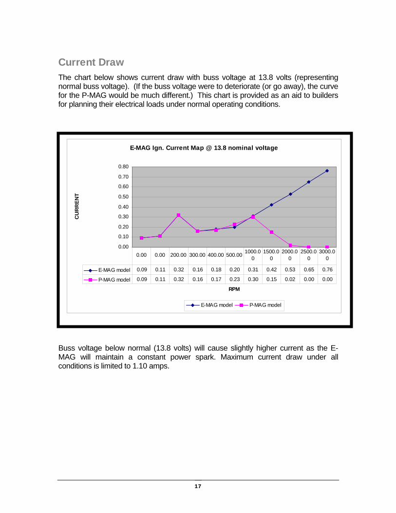
Current Draw The chart below shows current draw with buss voltage at 13.8 volts (representing normal buss voltage). (If the buss voltage were to deteriorate (or go away), the curve for the P-MAG would be much different.) This chart is provided as an aid to builders for planning their electrical loads under normal operating conditions.
Buss voltage below normal (13.8 volts) will cause slightly higher current as the E-MAG will maintain a constant power spark. Maximum current draw under all conditions is limited to 1.10 amps.
E-MAG Ign. Current Map @ 13.8 nominal voltage
0.00
0.10
0.20
0.30
0.40
0.50
0.60
0.70
0.80
RPM
CU
RR
ENT
E-MAG model P-MAG model
E-MAG model 0.09 0.11 0.32 0.16 0.18 0.20 0.31 0.42 0.53 0.65 0.76
P-MAG model 0.09 0.11 0.32 0.16 0.17 0.23 0.30 0.15 0.02 0.00 0.00
0.00 0.00 200.00 300.00 400.00 500.00 1000.00
1500.00
2000.00
2500.00
3000.00