installation, operating and service instructions cls
TRANSCRIPT

INSTALLATION, OPERATING AND SERVICE INSTRUCTIONS
CLS SERIES CAST IRON OIL-FIRED BOILER
nonoitamrofnignikeesnehW.rotcartnocgnitaehruoyllac,reliobotsriaperroecivresroF.lebaLgnitaRnonwohssarebmuNlaireSdnarebmuNledoMrelioBedivorp,reliob
rebmuNledoMrelioB rebmuNlaireSrelioB etaDnoitallatsnI
___P-_-SLC _______6rotcartnoCgnitaeH rebmuNenohP
sserddA
M24350R6-11/09 Price - $3.00
2
IMPORTANT INFORMATION - PLEASE READ THIS PAGE CAREFULLY
1. THISBOILERHASLIMITEDWARRANTIES,COPIESOFWHICHAREPRINTEDONTHEBACKCOVEROFTHISMANUAL.
2. THISBOILERISSUITABLEFORINSTALLATIONONCOMBUSTIBLEFLOORING.BOILERCANNOTBEIN-STALLEDONCARPETING.
3. ALLBOILERSMUSTBEINSTALLEDINACCORDANCEWITHNATIONAL,STATEANDLOCALPLUMBING,HEATINGANDELECTRICALCODESANDTHEREGULATIONSOFTHESERVINGUTILITIESWHICHMAYDIF-FERFROMTHISMANUAL.AUTHORITIESHAVINGJURISDICTIONSHOULDBECONSULTEDBEFOREINSTAL-LATIONSAREMADE.
INALLCASES,REFERENCESHOULDBEMADETOTHEFOLLOWINGSTANDARDS:A. CurrentEditionofAmericanNationalStandardANSI/NFPA31,“InstallationofOilBurningEquipment”,forclearancesbetweenboiler,ventconnectorand
combustiblematerial.B. CurrentEditionofAmericanNationalStandardANSI/NFPA211,“Chimneys,Fireplaces,Vents,andSolidFuelBurningAppliances”,ForChimneyrequire-
ments,typeofventingmaterialandclearancesbetweenventconnectorpipeandcombustiblematerials.C. CurrentEditionofAmericanSocietyofMechanicalEngineersASMECSD-1,“ControlsandSafetyDevicesforAutomaticallyFiredBoilers”,forassembly
andoperationsofcontrolsandsafetydevices.
4. ALLHEATINGSYSTEMSSHOULDBEDESIGNEDBYCOMPETENTCONTRACTORSANDONLYPERSONSKNOWLEDGEABLEINTHELAYOUTANDINSTALLATIONOFHYDRONICHEATINGSYSTEMSSHOULDAT-TEMPTINSTALLATIONOFANYBOILER.
5. THEBOILERMUSTBECONNECTEDTOANAPPROVEDCHIMNEYINGOODCONDITION.SERIOUSPROP-ERTYDAMAGECOULDRESULTIFTHEBOILERISCONNECTEDTOADIRTYORINADEQUATECHIMNEY.THEINTERIOROFTHECHIMNEYFLUEMUSTBEINSPECTEDANDCLEANEDBEFORETHESTARTOFTHEHEATINGSEASONANDSHOULDBEINSPECTEDPERIODICALLYTHROUGHOUTTHEHEATINGSEASONFORANYOBSTRUCTIONS.ACLEANANDUNOBSTRUCTEDCHIMNEYFLUEISNECESSARYTOALLOWNOXIOUSFUMESTHATCOULDCAUSEINJURYORLOSSOFLIFETOVENTSAFELYANDWILLCONTRIBUTETOWARDMAINTAININGTHEBOILER’SEFFICIENCY.
6. READTHELITERATUREENCLOSEDBYTHEMANUFACTURERWITHTHEVARIOUSACCESSORYDEVICES.THESEACCESSORYDEVICESMUSTBEINSTALLEDANDUSEDACCORDINGTOTHERECOMMENDATIONSOFTHEMANUFACTURER.
7. ITISTHERESPONSIBILITYOFTHEINSTALLINGCONTRACTORTOSEETHATALLCONTROLSARECORRECT-LYINSTALLEDANDAREOPERATINGPROPERLYWHENTHEINSTALLATIONISCOMPLETED.
8. FOROPTIMUMPERFORMANCEANDSERVICEABILITYFROMTHISBOILERADHERETOTHEFOLLOWINGRECOMMENDATIONS:
A. DONOTTAMPERWITHTHEBOILERORCONTROLS.Retainyourcontractororacompetentservicemantoassurethattheboilerisproperlyadjustedandmaintained.
B. Havefluewayscleanedatleastonceayear-preferablyattheendoftheheatingseasontoremovesootandscale.Insideoffireboxshouldalsobecleanedatthesametime.
C. Haveoilburnerandcontrolscheckedatleastonceayearorasmaybenecessitated.
WARNINGThis boiler is designed to burn No. 2 fuel oil only. Do not use gasoline, crankcase drainings, or any oil containing gasoline. Never burn garbage or paper in this boiler. Do not convert to any solid fuel (i.e. wood, coal) or gaseous fuel (i.e. natural gas, LP/propane). All flammable debris, rags, paper, wood scraps, etc., should be kept clear of the boiler at all times. Keep the boiler area clean and free of fire hazards.
WARNINGHigh water temperatures increase the risk of burns or scalding injury. Install an automatic tempering (mixing) valve at the tankless heater outlet to avoid excessively hot water at the fixtures.
3
Table of Contents
I. GeneralInformation.............................3 II. InstallationInstructions.......................5 III. Operating&ServiceInstructions.......11
IV. BoilerCleaning..................................18 V. RepairParts........................................20
I. General Information
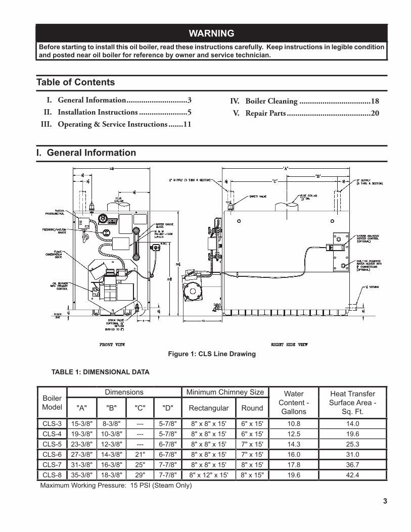
Figure 1: CLS Line Drawing
TABLE 1: DIMENSIONAL DATA
WARNINGBefore starting to install this oil boiler, read these instructions carefully. Keep instructions in legible condition and posted near oil boiler for reference by owner and service technician.
Boiler Model
Dimensions Minimum Chimney Size WaterContent - Gallons
Heat TransferSurface Area -
Sq. Ft."A" "B" "C" "D" Rectangular Round
CLS-3 15-3/8" 8-3/8" --- 5-7/8" 8" x 8" x 15' 6" x 15' 10.8 14.0CLS-4 19-3/8" 10-3/8" --- 5-7/8" 8" x 8" x 15' 6" x 15' 12.5 19.6CLS-5 23-3/8" 12-3/8" --- 6-7/8" 8" x 8" x 15' 7" x 15' 14.3 25.3CLS-6 27-3/8" 14-3/8" 21" 6-7/8" 8" x 8" x 15' 7" x 15' 16.0 31.0CLS-7 31-3/8" 16-3/8" 25" 7-7/8" 8" x 8" x 15' 8" x 15' 17.8 36.7CLS-8 35-3/8" 18-3/8" 29" 7-7/8" 8" x 12" x 15' 8" x 15" 19.6 42.4
Maximum Working Pressure: 15 PSI (Steam Only)
4
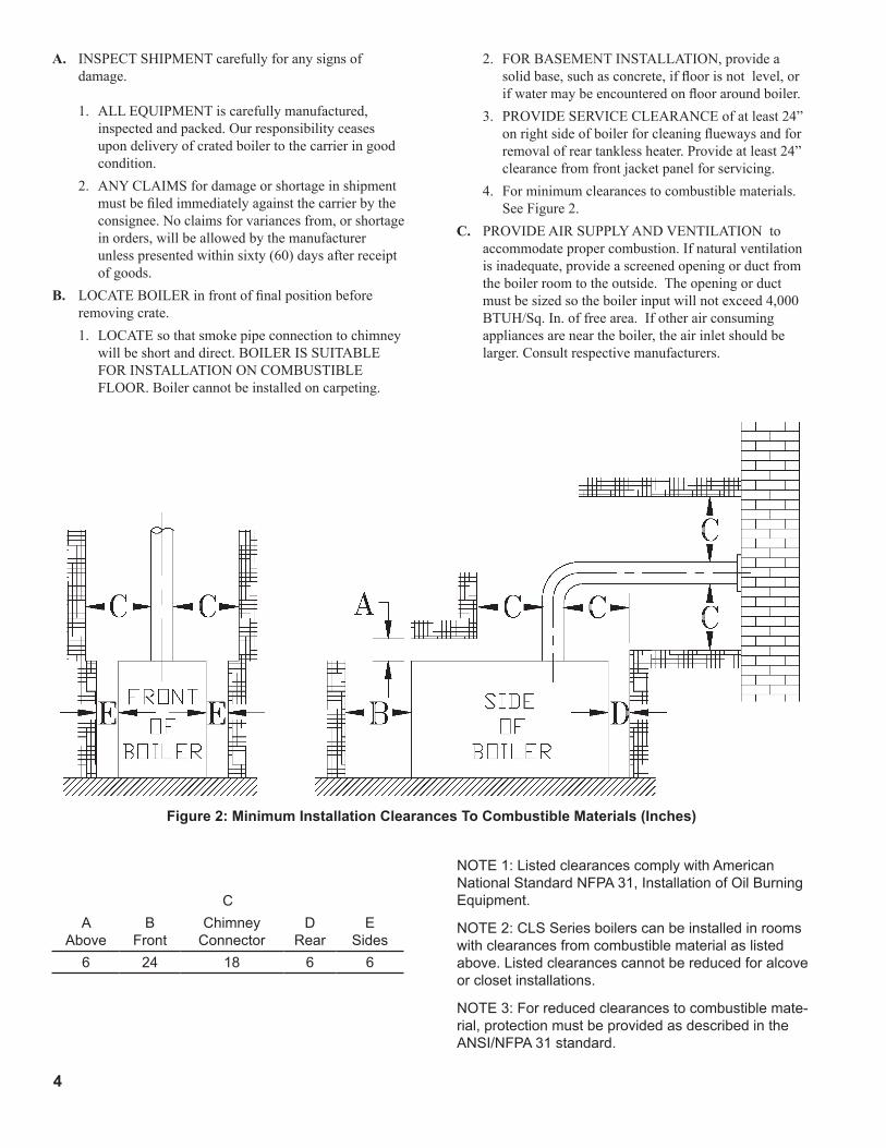
Figure 2: Minimum Installation Clearances To Combustible Materials (Inches)
A. INSPECTSHIPMENTcarefullyforanysignsofdamage.
1. ALLEQUIPMENTiscarefullymanufactured,inspectedandpacked.Ourresponsibilityceasesupondeliveryofcratedboilertothecarrieringoodcondition.
2. ANYCLAIMSfordamageorshortageinshipmentmustbefiledimmediatelyagainstthecarrierbytheconsignee.Noclaimsforvariancesfrom,orshortageinorders,willbeallowedbythemanufacturerunlesspresentedwithinsixty(60)daysafterreceiptofgoods.
B. LOCATEBOILERinfrontoffinalpositionbeforeremovingcrate.1. LOCATEsothatsmokepipeconnectiontochimney
willbeshortanddirect.BOILERISSUITABLEFORINSTALLATIONONCOMBUSTIBLEFLOOR.Boilercannotbeinstalledoncarpeting.
2. FORBASEMENTINSTALLATION,provideasolidbase,suchasconcrete,iffloorisnotlevel,orifwatermaybeencounteredonflooraroundboiler.
3. PROVIDESERVICECLEARANCEofatleast24”onrightsideofboilerforcleaningfluewaysandforremovalofreartanklessheater.Provideatleast24”clearancefromfrontjacketpanelforservicing.
4. Forminimumclearancestocombustiblematerials.SeeFigure2.
C. PROVIDEAIRSUPPLYANDVENTILATIONtoaccommodatepropercombustion.Ifnaturalventilationisinadequate,provideascreenedopeningorductfromtheboilerroomtotheoutside.Theopeningorductmustbesizedsotheboilerinputwillnotexceed4,000BTUH/Sq.In.offreearea.Ifotherairconsumingappliancesareneartheboiler,theairinletshouldbelarger.Consultrespectivemanufacturers.
CA
AboveB
FrontChimney
ConnectorD
RearE
Sides6 24 18 6 6
NOTE 1: Listed clearances comply with American National Standard NFPA 31, Installation of Oil Burning Equipment.
NOTE 2: CLS Series boilers can be installed in rooms with clearances from combustible material as listed above. Listed clearances cannot be reduced for alcove or closet installations.
NOTE 3: For reduced clearances to combustible mate-rial, protection must be provided as described in the ANSI/NFPA 31 standard.

5
II. Installation Instructions
A. REMOVECRATE.1. Removeallfastenersatcrateskid.2. Liftoutsidecontainerandremoveallother
insideprotectivespacersandbracing.Removemiscellaneoustrimbagcontainingsafety/reliefvalve,andpipefittings.
B. REMOVALOFBOILERFROMSKID1. Boilerissecuredtobasewith4carriagebolts,2on
leftsideand2onrightside.Removeallbolts.2. Tiltboilertorightandtorear.Usingrightrearleg
aspivot,rotateboiler90°inaclockwisedirection,andlowerleftsideofboilertofloor.Tiltboilerandremovecrateskid.Careshouldbeexercisedtopreventdamagetojacketorburner.
C. MOVEBOILERTOPERMANENTPOSITIONbyslidingorwalking.
D. INSPECTCOMBUSTIONTARGETWALLANDCOMBUSTIONCHAMBERLINER.1. OPENFLAMEOBSERVATIONDOORAND/
ORBURNERSWINGDOORonfrontofboiler.Useflashlighttoinspecttargetwallsecuredtorearsectionwithsilasticsealant.Inspectceramicfiberblanketsecuredtofloorofboilerwithwaterglassadhesive.Ifeitherisdamagedtheymustbereplaced.
E. CONNECTSUPPLYANDRETURNPIPINGTOHEATINGSYSTEM.1. CLEARANCES—Steamandhotwaterpipesshall
haveclearancesofatleast½”fromallcombustibleconstruction.
2. InstallSafetyValveintop¾"tapping.Use¾NPTx7"nippleand¾NPTcouplingincludedintrimbag.SafetyValvemustbeinstalledwithspindleinverticalposition.
3. OxygenContamination
CAUTIONOxygen contamination of the boiler water will cause corrosion of iron and steel boiler components, and can lead to boiler failure. New Yorker's standard warranty does not cover problems caused by oxygen contamination of boiler water.
Therearemanypossiblecausesofoxygencontaminationsuchas:
a. Additionofexcessivemake-upwaterasaresultofsystemleaks.
b. Absorptionthroughopentanksandfittings.c. Oxygenpermeablematerialsinthedistribution
system. Inordertoinsurelongproductlife,oxygensourcesshouldbeeliminated.Thiscanbeaccomplishedbytakingthefollowingmeasures:
a. Repairingsystemleakstoeliminatetheneedforadditionofmake-upwater.
b. Eliminatingopentanksfromthesystem.c. Eliminatingand/orrepairingfittingswhichallow
oxygenabsorption.d. Useofnon-permeablematerialsinthe
distributionsystem.e. Isolatingtheboilerfromthesystemwaterby
installingaheatexchanger.F. CONNECTTANKLESSHEATERPIPINGAS
SHOWNINFigure3.SeeTable2forTanklessHeaterRatings.
THEFOLLOWINGGUIDELINESSHOULDBEFOL-LOWEDWHENPIPINGTHETANKLESSHEATER:
1. FLOWREGULATION—Ifflowthroughtheheaterisgreaterthanitsrating,thesupplyofadequatehotwatermaynotbeabletokeepupwiththedemand.
NOTICEBefore using copper for steam piping, consider the following characteristics of copper piping:
1) High coefficient of thermal expansion can induce mechanical stresses and cause expansion/contraction noises if not accounted for in the piping system design and installation,
2) High heat transfer rate (heat loss) of un-insulated copper piping must be included in the normal piping and pickup factors used to size the boiler,
3) Soldering or brazing pastes and fluxes that end up in the system can cause poor heat transfer, surging, an unsteady water line and wet steam if not thoroughly removed during boil out procedure and,
4) Galvanic corrosion of the adjoining metal may occur due to dissimilar metals in certain water chemistries if dielectric unions are not used.
6
Forthisreasonaflowregulatormatchingtheheaterratingshouldbeinstalledinthecoldwaterlinetotheheater.Theflowregulatorshouldpreferablybelocatedbelowtheinlettotheheaterandaminimumof3’awayfromtheinletsothattheregulatorisnotsubjectedtoexcesstemperaturesthatmayoccurduring“off”periodswhenitispossibleforheattobeconductedbackthroughthesupplyline.Theflowregulatoralsolimitstheflowofsupplywaterregardlessofinletpressurevariationsintherangeof20to125psi.
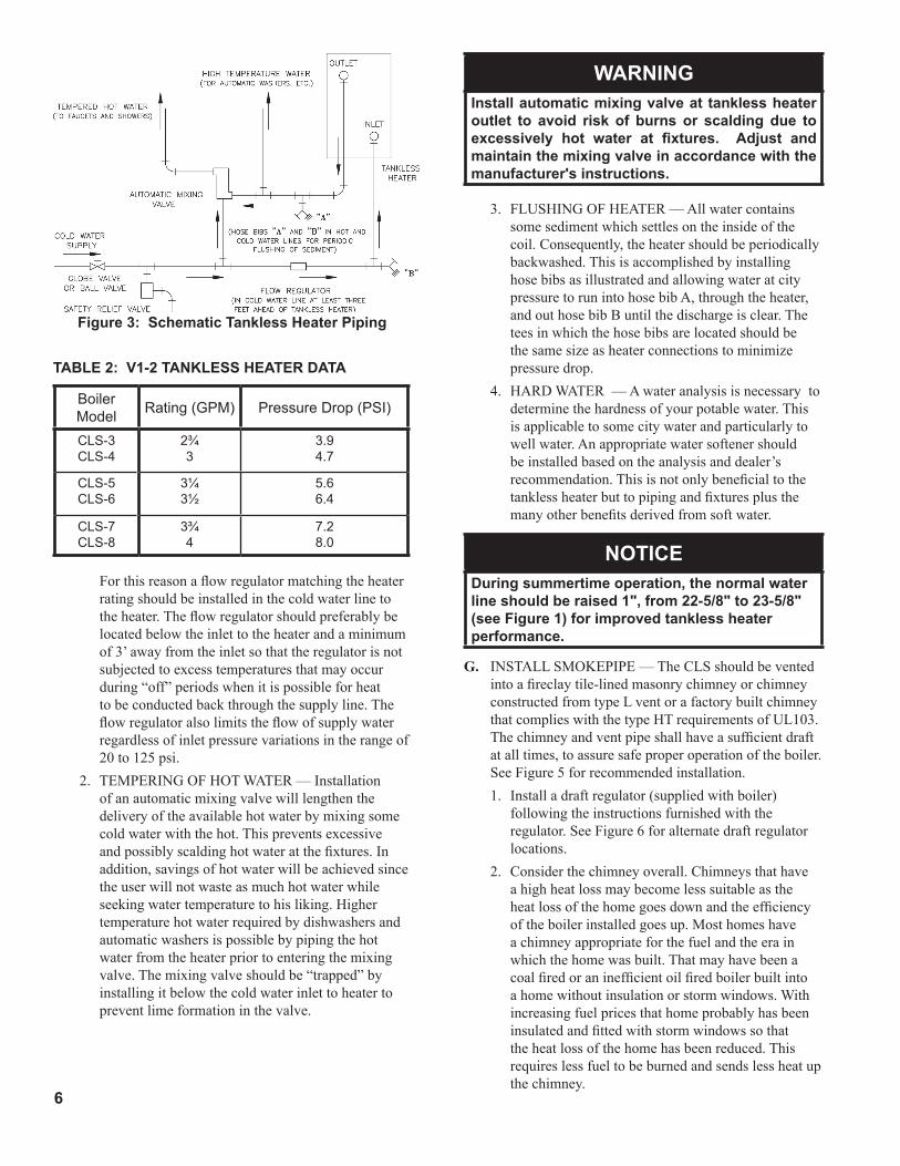
2. TEMPERINGOFHOTWATER—Installationofanautomaticmixingvalvewilllengthenthedeliveryoftheavailablehotwaterbymixingsomecoldwaterwiththehot.Thispreventsexcessiveandpossiblyscaldinghotwateratthefixtures.Inaddition,savingsofhotwaterwillbeachievedsincetheuserwillnotwasteasmuchhotwaterwhileseekingwatertemperaturetohisliking.Highertemperaturehotwaterrequiredbydishwashersandautomaticwashersispossiblebypipingthehotwaterfromtheheaterpriortoenteringthemixingvalve.Themixingvalveshouldbe“trapped”byinstallingitbelowthecoldwaterinlettoheatertopreventlimeformationinthevalve.
WARNINGInstall automatic mixing valve at tankless heater outlet to avoid risk of burns or scalding due to excessively hot water at fixtures. Adjust and maintain the mixing valve in accordance with the manufacturer's instructions.
3. FLUSHINGOFHEATER—Allwatercontainssomesedimentwhichsettlesontheinsideofthecoil.Consequently,theheatershouldbeperiodicallybackwashed.ThisisaccomplishedbyinstallinghosebibsasillustratedandallowingwateratcitypressuretorunintohosebibA,throughtheheater,andouthosebibBuntilthedischargeisclear.Theteesinwhichthehosebibsarelocatedshouldbethesamesizeasheaterconnectionstominimizepressuredrop.
4. HARDWATER—Awateranalysisisnecessarytodeterminethehardnessofyourpotablewater.Thisisapplicabletosomecitywaterandparticularlytowellwater.Anappropriatewatersoftenershouldbeinstalledbasedontheanalysisanddealer’srecommendation.Thisisnotonlybeneficialtothetanklessheaterbuttopipingandfixturesplusthemanyotherbenefitsderivedfromsoftwater.
NOTICEDuring summertime operation, the normal water line should be raised 1", from 22-5/8" to 23-5/8" (see Figure 1) for improved tankless heater performance.
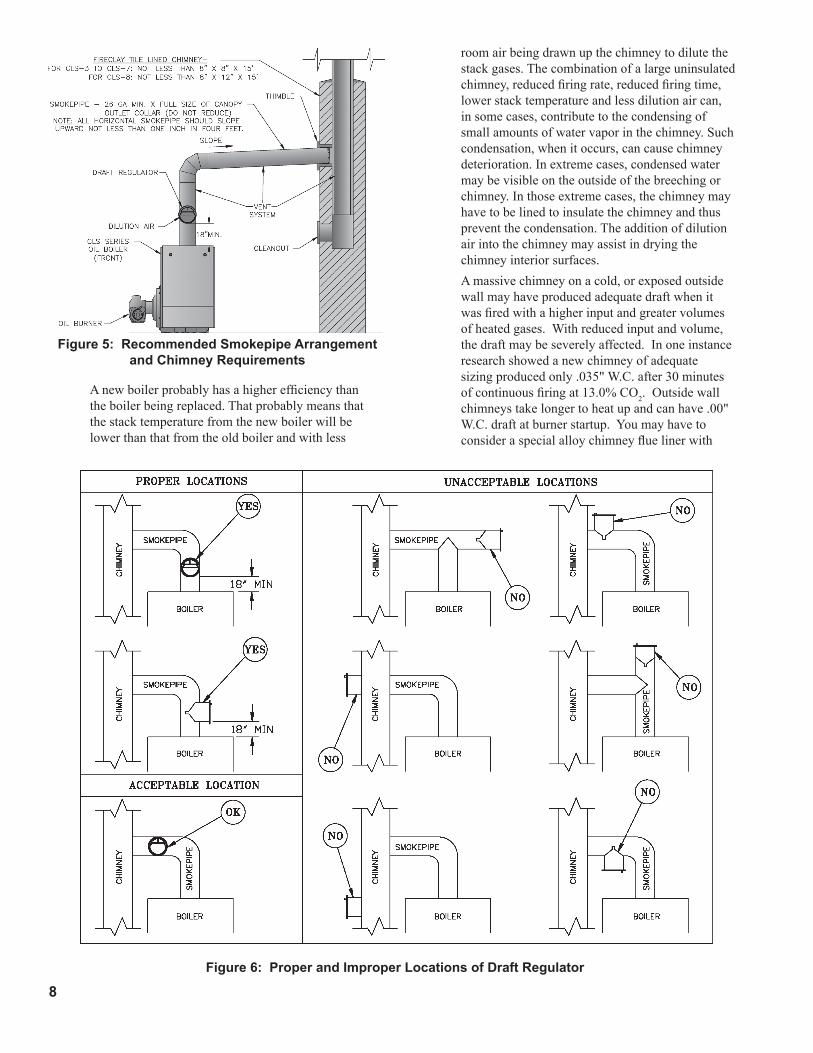
G. INSTALLSMOKEPIPE—TheCLSshouldbeventedintoafireclaytile-linedmasonrychimneyorchimneyconstructedfromtypeLventorafactorybuiltchimneythatcomplieswiththetypeHTrequirementsofUL103.Thechimneyandventpipeshallhaveasufficientdraftatalltimes,toassuresafeproperoperationoftheboiler.SeeFigure5forrecommendedinstallation.1. Installadraftregulator(suppliedwithboiler)
followingtheinstructionsfurnishedwiththeregulator.SeeFigure6foralternatedraftregulatorlocations.
2. Considerthechimneyoverall.Chimneysthathaveahighheatlossmaybecomelesssuitableastheheatlossofthehomegoesdownandtheefficiencyoftheboilerinstalledgoesup.Mosthomeshaveachimneyappropriateforthefuelandtheerainwhichthehomewasbuilt.Thatmayhavebeenacoalfiredoraninefficientoilfiredboilerbuiltintoahomewithoutinsulationorstormwindows.Withincreasingfuelpricesthathomeprobablyhasbeeninsulatedandfittedwithstormwindowssothattheheatlossofthehomehasbeenreduced.Thisrequireslessfueltobeburnedandsendslessheatupthechimney.
TABLe 2: V1-2 TAnKLeSS HeATer DATA
Boiler Model Rating (GPM) Pressure Drop (PSI)
CLS-3CLS-4
2¾3
3.94.7
CLS-5CLS-6
3¼3½
5.66.4
CLS-7CLS-8
3¾4
7.28.0
Figure 3: Schematic Tankless Heater Piping

�
Figu
re 4
: rec
omm
ende
d B
oile
r Pip
ing
For G
ravi
ty r
etur
n St
eam
Boi
ler
8
Anewboilerprobablyhasahigherefficiencythantheboilerbeingreplaced.Thatprobablymeansthatthestacktemperaturefromthenewboilerwillbelowerthanthatfromtheoldboilerandwithless
Figure 6: Proper and Improper Locations of Draft regulator
Figure 5: recommended Smokepipe Arrangement and Chimney requirements
roomairbeingdrawnupthechimneytodilutethestackgases.Thecombinationofalargeuninsulatedchimney,reducedfiringrate,reducedfiringtime,lowerstacktemperatureandlessdilutionaircan,insomecases,contributetothecondensingofsmallamountsofwatervaporinthechimney.Suchcondensation,whenitoccurs,cancausechimneydeterioration.Inextremecases,condensedwatermaybevisibleontheoutsideofthebreechingorchimney.Inthoseextremecases,thechimneymayhavetobelinedtoinsulatethechimneyandthuspreventthecondensation.Theadditionofdilutionairintothechimneymayassistindryingthechimneyinteriorsurfaces.
Amassivechimneyonacold,orexposedoutsidewallmayhaveproducedadequatedraftwhenitwasfiredwithahigherinputandgreatervolumesofheatedgases.Withreducedinputandvolume,thedraftmaybeseverelyaffected.Inoneinstanceresearchshowedanewchimneyofadequatesizingproducedonly.035"W.C.after30minutesofcontinuousfiringat13.0%CO2.Outsidewallchimneystakelongertoheatupandcanhave.00"W.C.draftatburnerstartup.Youmayhavetoconsideraspecialalloychimneyfluelinerwith

9
Figure 8
Figure �
Lift "H"(See Figure)
Maximum Length of Tubing"H" + "R" (See Figure)
3/8" ODTubing (3 GPH)
1/2" ODTubing (3 GPH)
0' 84' 100'1' 78' 100'2' 73' 100'3' 68' 100'4' 63' 100'5' 57' 100'6' 52' 100'7' 47' 100'8' 42' 100'9' 36' 100'
10' 31' 100'11' 26' 100'12' 21' 83'13' --- 62'14' --- 41'
TABLE 3: SINGLE STAGE UNITS (3450 RPM) TWO PIPE SYSTEMS
Lift "H"(See Figure)
Maximum Length of Tubing"H" + "R" (See Figure)
3/8" ODTubing (3 GPH)
1/2" ODTubing (3 GPH)
0' 93' 100'2' 85' 100'4' 77' 100'6' 69' 100'8' 60' 100'
10' 52' 100'12' 44' 100'14' 36' 100'16' 27' 100'18' --- 76'
TABLE 4: TWO-STAGE UNITS (3450 RPM) TWO PIPE SYSTEMS
insulationarounditandastabilizingdraftcaporevenadraftinducingfaninseverecases.
3. Forthesamereasonsasin(2.)above,heatextractorsmountedintothebreechingarenotrecommended.
H. INSTALLELECTRICWIRINGinaccordancewithNationalElectricalCodeandlocalregulations.AseparateELECTRICALCIRCUITshouldberunfrommeterwithaFusedDisconnectSwitchintheCircuit.WiringshouldconformtoFigure9.
I. FUELUNITSANDOILLINES SINGLE-PIPEOILLINESStandardburnersare
providedwithsingle-stage3450rpmfuelunitswiththeby-passplugremovedforsingle-pipeinstallations.
Thesingle-stagefuelunitmaybeinstalledsingle-pipewithgravityfeedorlift.Maximumallowableliftis8feet.SeeFigure7.
TWO-PIPEOILLINESFortwo-pipesystemswheremoreliftisrequired,thetwo-stagefuelunitisrecommended.Table3(single-stage)andTable4(two-stage)showallowableliftandlengthsof3/8-inchand1/2-inchODtubingforbothsuctionandreturnlines.RefertoFigure8.
Besurethatalloillineconnectionsareabsolutelyairtight.Checkallconnectionsandjoints.Flaredfittingsarerecommended.Donotusecompressionfittings.
Opentheair-bleedvalveandstarttheburner.Forcleanbleed,slipa3/16"IDhoseovertheendofthebleedvalveandbleedintoacontainer.Continuetobleedfor15secondsafteroilisfreeofairbubbles.Stopburnerandclosevalve.
10
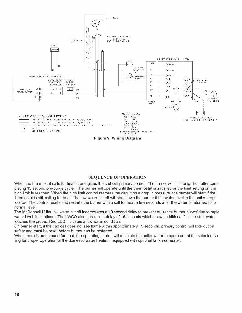
Figure 9: Wiring Diagram
SEQUENCEOFOPERATIONWhen the thermostat calls for heat, it energizes the cad cell primary control. The burner will initiate ignition after com-pleting 15 second pre-purge cycle. The burner will operate until the thermostat is satisfied or the limit setting on the high limit is reached. When the high limit control restores the circuit on a drop in pressure, the burner will start if the thermostat is still calling for heat. The low water cut off will shut down the burner if the water level in the boiler drops too low. The control resets and restarts the burner with a call for heat a few seconds after the water is returned to its normal level.The McDonnell Miller low water cut off incorporates a 10 second delay to prevent nuisance burner cut-off due to rapid water level fluctuations. The LWCO also has a time delay of 15 seconds which allows additional fill time after water touches the probe. Red LED indicates a low water condition.On burner start, if the cad cell does not see flame within approximately 45 seconds, primary control will lock out on safety and must be reset before burner can be restarted.When there is no demand for heat, the operating control will maintain the boiler water temperature at the selected set-ting for proper operation of the domestic water heater, if equipped with optional tankless heater.

11
III. Operating and Service Instructions3. Attachaplastichosetofuelpumpventfittingand
provideapantocatchtheoil.4. REMOVEGAUGEPORTPLUGfromfuelpump
andinstallpressuregaugecapableofreadingatleast150PSI.
5. OPENFLAMEOBSERVATIONDOORonfrontofboiler.
H. STARTOILBURNER.1. Openventfittingonfuelpump.2. TURN‘ON’BURNERserviceswitchandallow
burnertorununtiloilflowsfromventfittinginaSOLIDstreamwithoutairbubblesforapproximately10seconds.
3. Closeventfittingandburnerflameshouldstartimmediatelyafterpre-purgeiscomplete.Pre-purgepreventsburnerflameuntil15secondshaselapsedafterinitialpowerisappliedtoburner.Duringpre-purge,themotorandignitorwilloperatebuttheoilvalvewillremainclosed.RefertoOilPrimaryControlInstructionsformoredetails.
I. ADJUSTOILPRESSURE.1. Locateoilpressureadjustingscrewandturnscrew
toobtain140PSIpressure.2. DONOTREMOVEPRESSUREGAUGEuntil
later.J. OTHERADJUSTMENTS
1. ADJUSTTHEAIRBANDAND/ORAIRSHUTTER.
Adjustairsupplybylooseninglockscrewsandmovingtheairshutterandifnecessarytheairband.RefertoTable5forpreliminarysettings.
2. ADJUSTTHECOMBUSTIONHEAD. CLS-3thruCLS-7: "F"headburnershaveafixedheadwhichisnon-
adjustable.TocheckcombustionheadlocationrefertoFigure10.
CLS-8: “V1”(variable)headburnershavetheabilityto
controlairbymovingtheheadeitherforwardorback.
Loosentheadjustingplateassemblyholddownscrew.SlidetheheadandplatetotherequiredfiringratesettingasshowninFigure11.Tightenthescrewandknurlednut.
ItmightbenecessarytomovetheheadforwardorbackonepositionatatimetooptimizethesmokeandCO2readings.SeeFigure11.
3. ADJUSTDRAFTREGULATORforadraft of—.02”(watergauge)overthefireafterchimney
hasreachedoperatingtemperatureandwhileburnerisrunning.
A. ALWAYSINSPECTINSTALLATIONBEFORESTARTINGBURNER.
B. FILLHEATINGSYSTEMWITHWATER. NOTE:Itisimportant,especiallyinasteamsystem,
toproperlyremovetheoilanddirtfromthesystem.Failuretocleanthesystemcanresultinerraticwaterlinesandsurging.1. Cleanheatingsystemifboilerwaterorcondensate
returnwaterisdirtyoriferraticwaterlinesorsurgingexistafterafewdaysofboileroperation.
Refertostep"N"forpropercleaninginstructionsforsteamboilers.
2. Fillboilertonormalwaterline.RefertoFigure1.C. CHECKCONTROLS,WIRINGANDBURNERtobe
surethatallconnectionsaretightandburnerisrigid,thatallelectricalconnectionshavebeencompletedandfusesinstalled,andthatoiltankisfilledandoillineshavebeentested.
D. LUBRICATION—Followinstructiononburnerandcirculatorlabeltolubricate,ifoillubricated.Mostmotorscurrentlyusedonresidentialtypeburnersemploypermanentlylubricatedbearingsandthusdonotrequireanyfieldlubrication.Waterlubricatedcirculatorsdonotneedfieldlubrication.
Donotover-lubricate.Thiscancauseasmuchtroubleasnolubricationatall.
E. SETCONTROLSwithburnerserviceswitchturned“OFF”.1. SETROOMTHERMOSTATabout10°aboveroom
temperature.2. PRESSREDRESETBUTTONonprimarycontrol
(R8184G)andrelease.3. Setcut-inpressureonPA404pressuretrolforthree
(3)psianddifferentialpressurefortwo(2)psi.Thesepressuresmaybevariedtosuitindividualrequirementsofinstallation.
4. OnSTEAMBOILERSWITHTANKLESSDOMESTICWATERHEATERS,setboilerwatertemperaturedialonL4006operatingcontrolat190°F(max.).Setdifferentialat10°.
F. REMOVEGUNASSEMBLY1. Itemstobecheckedarenozzlesize,type,andangle;
headsize(andsettingonMD(V1)head);gunsetting;andpositioningofelectrodes.ThisinformationsisshowninFigures10and11andTable5.
2. Reinstallgunassembly.G. ADJUSTOILBURNERBEFORESTARTING.
1. SETBURNERAIRBANDANDAIRSHUTTER,seeTable5.
2. OPENALLOILLINEVALVES.
12
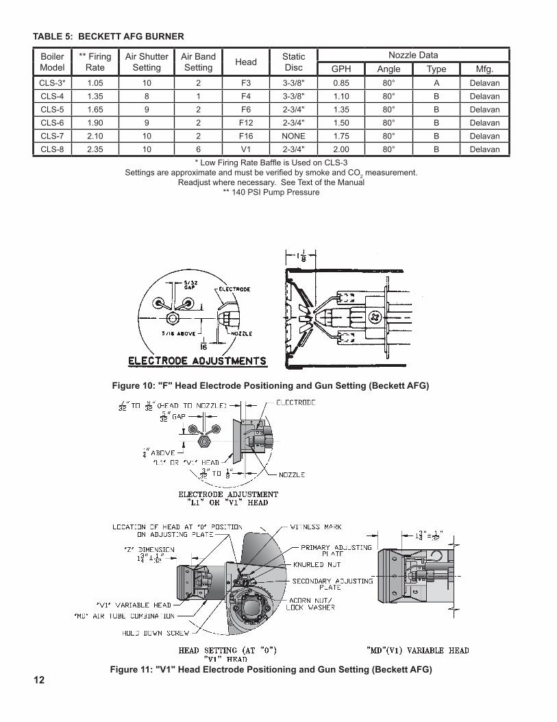
Figure 10: "F" Head Electrode Positioning and Gun Setting (Beckett AFG)
Figure 11: "V1" Head Electrode Positioning and Gun Setting (Beckett AFG)
Boiler Model
** Firing Rate
Air Shutter Setting
Air Band Setting Head Static
DiscNozzle Data
GPH Angle Type Mfg.CLS-3* 1.05 10 2 F3 3-3/8" 0.85 80° A DelavanCLS-4 1.35 8 1 F4 3-3/8" 1.10 80° B DelavanCLS-5 1.65 9 2 F6 2-3/4" 1.35 80° B DelavanCLS-6 1.90 9 2 F12 2-3/4" 1.50 80° B DelavanCLS-7 2.10 10 2 F16 NONE 1.75 80° B DelavanCLS-8 2.35 10 6 V1 2-3/4" 2.00 80° B Delavan
* Low Firing Rate Baffle is Used on CLS-3Settings are approximate and must be verified by smoke and CO2 measurement.
Readjust where necessary. See Text of the Manual** 140 PSI Pump Pressure
TABLe 5: BeCKeTT AFG Burner

13
nozzlewillcompresswhenburnerisonandwillexpandwhenburnerstops,causingoiltosquirtfromnozzleatlowpressureasburnerslowsdownandcausingnozzletodripafterburnerstops.Usuallycyclingtheburneroperationabout5to10timeswillridoillineofthisair.
2. IFNOZZLECONTINUESTODRIP,repeatstepK.1.Ifthisdoesnotstopthedripping,removecutoffvalveandseat,andwipebothwithacleanclothuntilclean,thenreplaceandreadjustoilpressure.Ifdrippingorafterburnpersistreplacefuelpump.
L. TESTCONTROLS.
WARNINGBefore installation of the boiler is considered complete, the operation of all boiler controls must be checked, particularly the primary control and high limit control.
1. Checkthermostatoperation.Raiseandlowerthermostatsettingasrequiredtostartandstopburner.
2. VERIFYPRIMARYCONTROLSAFETYFEATURESusingproceduresoutlinedinInstructionsfurnishedwithcontrol(Seebackofcontrolcover)orinstructionsasfollows:
CHECKOUTPROCEDURE
CAUTION
a. Checkwiringconnections.Closelineswitch.Checkpoweratcontrol.
PRIMARYRELAYTESTb. Disconnectcadcellleadsfromquickconnects
onundersideofprimarycontrol.Resetsafetyswitch.
c. Setcontrollertocallforheat.Burnershouldstart.
d. Jumperthequickconnectterminalswithin15to30seconds.Burnershouldrun.
e. RemoveterminalJumper.Burnershutsdowninapproximately15to60seconds.
f. Ifburneroperatesasdescribed,relayisgood.Ifnot,installnewrelay.
CADCELLTESTg. Openlineswitch.Cleancellfaceandseethat
cellissecurelyinsocket.Reconnectleads.Resetsafetyswitch.
h. Closelineswitch.Ifburnerstartsandrunsbeyondsafetyswitchcut-outtime,cellisgood.Ifnot,installnewcell.
4. READJUSTAIRBANDSonburnerforalightorangecoloredflamewhilethedraftoverthefireis—.02”.Useasmoketesterandadjustairforminimumsmoke(nottoexceed#1)withaminimumofexcessair.MakefinalcheckusingsuitableinstrumentationtoobtainaCO2of11.5to12.5%withdraftof—.02”(watergauge)infirebox.Thesesettingswillassureasafeandefficientoperatingcondition.Iftheflameappearsstringyinsteadofasolidfire,tryanothernozzleofthesametype.Flameshouldbesolidandcompact.Afteralladjustmentsaremaderecheckforadraftof—.02”overthefire.
5. TURN“OFF”BURNERandremovepressuregauge.Installgaugeportplugandtighten.Startburneragain.
6. CADCELLLOCATIONANDSERVICE Theburnerissuppliedwithacadmiumsulfideflame
detectormountedatthefactory,mountedonthebottomoftheignitor.SeeFigure12.Toservicecadcellortoreplacethepluginportion,swingopentheignitor.Afterserviceiscomplete,besuretofastendowntheignitor.
Figure 12: Cad Cell Location
7. FLAMEFAILURE TheCLSboilercontrolsoperatetheburner
automatically.Ifforunknownreasonstheburnerceasestofireandtheresetbuttonontheprimarycontrolhastripped,theburnerhasexperiencedignitionfailure.Beforepressingtheresetbuttoncallyourservicemanimmediately.
WARNINGDo not attempt to start the burner when excess oil has accumulated, when the unit is full of vapor, or when the combustion chamber is very hot.
K. CHECKFORCLEANCUTOFFOFBURNER.1. AIRINTHEOILLINEbetweenfuelunitand
FORSERVICEMANONLY

14
3. WARNING—CheckHighLimitControl—JumperThermostatTerminals.Allowburnertooperateuntilshut-downbylimit.Installationisnotconsideredcompleteuntilthischeckhasbeenmade.
REMOVEJUMPER.4. Checklowwatercutoffcontrolwithwaterlevelat
normalwaterline(seeFigure1).Raisethermostatsettingtoallowburnertooperate.Openboilerdraintoallowwaterleveltodroptobottomofsightglassuntilburneroperationisshut-downbylowwatercutoff.
Closeboilerdrainandrefilltonormalwaterline.Burnershouldautomaticallyrestartduringfill.Lowerthermostatsetting.
5. Checkoperatingcontrolonboilerequippedwithtanklessheaters.Withburneroff,drawhotwateruntilburnerstarts,thenturnoffhotwaterandcheckburnershut-down.
IFCONTROLSDONOTMEETREQUIREMENTSOUTLINEDINPARAGRAPHL.,REPLACECONTROLANDREPEATCHECK-OUTPROCEDURES.
M. MAINTENANCEOFPROBELOWWATERCUTOFF
WARNINGProbe and float type low water cut-off devices require annual inspection and maintenance.
1. Althoughthesedevicesaresolidstateintheiroperation,theprobeisexposedtopossiblecontaminationintheboilerwaterandsubjecttofouling.
2. Itisimportanttophysicallyremovetheprobefromtheboilertappingannuallyandinspectthatprobeforaccumulationofscaleorsediment.
3. Followthesestepstoinspect,cleanand/orreplacetheprobe:a. Turnoffelectricservicetotheboiler.b. Drainboilerwatertoalevelbelowthetapping
fortheprobe.
DANGERAssure that the boiler is at zero pressure before removing the LWCO probe. Do not rely on the pressure gauge to indicate that the boiler is at zero pressure. Open the safety valve to relieve all internal pressure prior to proceeding. Safety valve discharge piping must be piped such that the potential for burns is eliminated.
c. Disconnectwiringconnectionsbetweenthelowwatercutoffcontrolandtheprobe.
d. Dismountthelowwatercutoffcontrolfromtheprobe.
e. Unscrewtheprobefromtheboilertapping.f. Inspectthatportionoftheprobethatisexposed
totheboilerwaterforascaleorsedimentbuildup.
g. Lightdepositsmayberemovedbywipingtheprobewithadampcloth.Wipingtheprobewithaclothsoakedinvinegarwillremovemoretenaciouslimedeposits.Themoststubborndepositsmayberemovedfromtheprobebyusingadilutedamount,3partsofwaterto1partofphosphoricacid(H2PO4).
CAUTIONexercise caution when handling phosphoric acid and follow the instruction label on its container.
h. Cleanthepipethreadsoftheprobetoremoveold,hardenedpipedopeandotherforeignmatter.
i. Applyamoderateamountofgoodqualitypipedopetothepipethreadsontheprobe,leavingthetwoendthreadsbare.DonotusePTFE(Teflon)tape.
j. Screwtheprobeintotheboilertapping.k. Mountthelowwatercutoffcontrolontheprobe.l. Reconnectthecontroltoprobewiring.m.Filltheboilertoitsnormalwaterline.n. Addboilerwatertreatmentcompoundasneeded
(refertoparagraphN.).o. Restoreelectricservicetotheboiler.p. Fireburnertobringthewaterintheboilertoa
boiltodriveofffreeoxygen.q. WARNING—BEFORERETURNING
BOILERTOSERVICE:FollowthelowwatercutoffcheckoutprocedureinstepL.4.
N. BOILERANDSYSTEMCLEANINGINSTRUCTIONSFORTROUBLEFREEOPERATION1. Oil,greases&sedimentswhichaccumulateinanew
boilerandpipingmustberemovedfromthesysteminordertopreventanunsteadywaterlineandcarryoverofthewaterintothesupplymainaboveboiler.
Operatetheboilerwithsteamintheentiresystemforafewdaysallowingthecondensatetoreturntotheboiler.Ifthecondensatecantemporarilybewasted,operateboileronlyforthelengthoftimeittakesforcondensatetorunclear.Ifthelattercannotbeachievedorifthecondensateisreturnedtotheboiler,boilouttheboilerusingtheSURFACEBLOWOFFconnection.

15
b. Drawabout5gallonsofhotwaterfromboilerintoacontaineranddissolveintoittheappropriateamountofarecommendedboiloutcompound.Removesafetyvalvefromboilerandpourthissolutionintoboiler,thenreinstallsafetyvalve.
c. Turnonoilburnerandkeepoperatingwhilefeedingwatertoboilerslowly.Thiswillraisewaterlevelinboilerslowlysothatwaterwillbeboilinghotandwillriseslowlyintosupplymainandbackthroughreturnmain,flowingfromdrainhoseatabout180°F.Continueuntilwaterrunsclearfromdrainhoseforatleast30minutes.
d. Stopfeedingwatertoboilerbutcontinueoperatingoilburneruntilexcesswaterinboilerflowsoutthroughsupplymainandwaterlowers(bysteaming)untilitreachesnormallevelinboiler.Turnoffoilburner.Drainboiler.Openallradiatorvalves.Reinstallallsupplymainairvalves.OpengatevalveinHartfordLoop.
e. Whenboilerhascooleddownsufficiently(crownsheetofsectionsarenottoohottotouch),closethedrainvalvesatboilerandinreturnmainandfeedwaterslowlyuptonormallevelinboiler.Turnonoilburnerandallowboilertosteamfor10minutes,thenturnoffburner.Drawoffonequartofwaterfrombottomgaugeglassfittinganddiscard.Drawoffanotherquartsampleandifthissampleisnotclear,repeatthecycleofdrainingtheboilerandreturnmainandrefillingtheboileruntilsampleisclear.
f. Iftheboilerwaterbecomesdirtyagainatalaterdateduetoadditionalsedimentloosenedupinthepiping,closegatevalveinHartfordLoop,opendrainvalveinreturnmain,turnonoilburnerandallowCondensatetoflowtodrainuntilithasrunclearforatleast30minuteswhilefeedingwatertoboilersoastomaintainnormalwaterlevel.Turnoffoilburner,drainboiler,opengatevalveinHartfordLoop,thenrepeatstep1above.
5. MakepHorAlkalinityTest. Afterboilerandsystemhavebeencleanedand
refilledaspreviouslydescribed,testthepHofthewaterinthesystem.Thiscaneasilybedonebydrawingasmallsampleofboilerwaterandtestingwithhydrionpaperwhichisusedinthesamemanneraslitmuspaper,exceptitgivesspecificreadings.AcolorchartonthesideofthesmallhydriondispensergivesthereadinginpH.Hydrionpaperisinexpensiveandobtainablefromanychemicalsupplyhouseorthroughyourlocaldruggist.ThepHshouldbehigherthan7,butlowerthan11.Addsomeofthewashoutchemical(causticsoda),ifnecessary,tobringthepHwithinthespecifiedrange.
a. Drainboileruntil1”ofwaterisvisibleingaugeglass.Runtemporary1½”pipelinefromthesurfaceblowoffconnectiontoanopendrainorsomeotherlocationwherehotwatermaybedischargedsafely.Donotinstallvalveinthisline.
b. Drainabout5gallonsofhotwaterfromboilerintoacontaineranddissolveintoitanappropriateamountofrecommendedboiloutcompound.Removesafetyvalveandaddsolutiontoboilerwaterthruexposedtappingusingafunnel.
NOTICECheck with local authorities or consult local water treatment services for acceptable chemical cleaning compounds.
c. Startburnerandoperatesufficientlytoboilthewaterwithoutproducingsteampressure.Boilforabout5hours.Openboilerfeedpipesufficientlytopermitasteadytrickleofwaterfromthesurfaceblowoffpipe.Continuethisslowboilingandtrickleofoverflowforseveralhoursuntilthewatercomingfromtheoverflowisclear.
d. Stopburneranddrainboilerinamannerandtoalocationthathotwatercanbedischargedwithsafety.
e. Refillboilertonormalwaterline.Ifwateringaugeglassdoesnotappeartobeclear,repeatsteps(a.thruc.)andboilouttheboilerforalongertime.
2. LowpressuresteamboilerssuchastheCLSSeriesshouldbemaintainedwithappropriatewatertreatmentcompounds.Addsuitablewatertreatmentcompoundsasrecommendedbyyourqualifiedwatertreatmentcompany.
3. Removetemporarysurfaceblowoffpiping,plugtappingandreinstallsafetyvalve.Boilorbringwatertemperatureto180°Fpromptlyinordertodriveoffthedissolvedgasesinthefreshwater.
4. Ifunsteadywaterline,foamingorprimingpersist,installgatevalveinHartfordLoopanddrainvalvesinreturnmainandatboilerasshowninFigure4andproceedasfollows:a. Connecthosesfromdrainvalvestofloordrain.
ClosegatevalveinHartfordLoopandopendrainvalveinreturnmain.Fillboilertonormalwaterlevel,turnonoilburnerandoperateboileratthiswaterlevelforatleast30minutesafterthecondensatebeginstorunhot,thenturnoffburner.
Closeallradiatorvalves.Removeallsupplymainairvalvesandplugtheopeningsinsupplymain.

16
6. Boilerisnowreadytobeputintoservice.
IMPORTANTIF, DURING NORMAL OPERATION, IT IS NECESSARY TO ADD MORE WATER PER MONTH THAN INDICATED BELOW, CONSULT A QUALIFIED SERVICE TECHNICIAN TO CHECK YOUR SYSTEM FOR LEAKS.
EXCESSIVE WATER ADDITION:(Gal/Month)
CLS-3: 5 CLS-4: 7 CLS-5: 8½
CLS-6: 10 CLS-7: 12 CLS-8: 13½
Aleakysystemwillincreasethevolumeofmake-upwater supplied to the boiler which can significantly shortenthelifeoftheboiler.Entrainedinmake-upwateraredissolvedmineralsandoxygen.Whenthefresh,coolmake-upwaterisheatedintheboilerthemineralsfalloutassedimentandtheoxygenescapesasagas.Bothcanresultinreducedboilerlife.Theaccumulationofsedimentcaneventuallyisolatethewaterfromcontactingthecastiron.Whenthishappensthecastironinthatareagetsextremelyhotandeventuallycracks.Thepresenceoffreeoxygenintheboilercreatesacorrosiveatmospherewhich,iftheconcentrationbecomeshighenough,cancorrodethecastironthroughfromtheinside.Sinceneitherofthesefailuretypesaretheresultofacastingdefectthewarrantydoesnotapply.Clearlyitisineveryone’sbestinteresttopreventthistypeoffailure.Themaintenanceofsystemintegrityisthebestmethodtoachievethis.
O. HINTSONCOMBUSTION1. NOZZLES—Althoughthenozzleisarelatively
inexpensivedevice,itsfunctioniscriticaltothesuccessfuloperationoftheoilburner.TheselectionofthenozzlesuppliedwiththeCLSboileristheresult of extensive testing to obtain the best flame shape and efficient combustion. Other brands of the samesprayangleandspraypatternmaybeusedbutmaynotperformattheexpectedlevelofCO2andsmoke.Nozzlesaredelicateandshouldbeprotectedfromdirtandabuse.Nozzlesaremass-producedandcanvaryfromsampletosample.Forallofthosereasonsasparenozzleisadesirableitemforaservicemantohave.
2. FLAMESHAPE—Lookingintothecombustionchamber through the observation door, the flame shouldappearstraightwithnosparklersrollinguptoward the crown of the chamber. If the flame drags totherightorleft,sendssparklersupwardormakeswetspotsonthetargetwall,thenozzleshouldbereplaced.Iftheconditionpersistslookforfuelleaks,airleaks,waterordirtinthefuelasdescribedinfollowingsteps.
3. FUELLEAKS—Anyfuelleakbetweenthepumpandthenozzlewillbedetrimentaltogoodcombustionresults.Lookforwetsurfacesintheairtube,undertheignitor,andaroundtheairinlet.Anysuchleaksshouldberepairedastheymaycauseerraticburningofthefuelandintheextremecasemay become a fire hazard.
4. AIRLEAKS—Anysuchleaksshouldberepaired,astheymaycauseerraticburningofthefuelandinextreme cases may become a fire hazard.
5. GASKETLEAKS—If11.5to12.5%CO2witha#1smokecannotbeobtainedinthebreeching,lookforairleaksaroundtheburnermountinggasket,observationdoor,andcanopygasket.SuchairleakswillcausealowerCO2readinginthebreeching.Thesmaller the firing rate the greater effect an air leak canhaveonCO2readings.
6. DIRT — A fuel filter is a good investment. Accidentalaccumulationofdirtinthefuelsystemcanclogthenozzleornozzlestrainerandproduceapoorspraypatternfromthenozzle.Thesmallerthefiring rate, the smaller the slots become in the nozzle andthemorepronetopluggingitbecomeswiththesameamountofdirt.
7. WATER—Waterinthefuelinlargeamountswillstallthefuelpump.Waterinthefuelinsmalleramountswillcauseexcessivewearonthepump,butmoreimportantlywaterdoesn’tburn.Itchillsthe flame and causes smoke and unburned fuel to passoutofthecombustionchamberandclogtheflueways of the boiler.
8. COLDOIL—Iftheoiltemperatureapproachingthefuelpumpis40°Forlowerpoorcombustionordelayedignitionmayresult.Coldoilishardertoatomizeatthenozzle.Thus,thespraydropletsgetlarger and the flame shape gets longer. An outside fueltankthatisabovegradeorhasfuellinesina
IMPORTANTSUCTION LINE LEAKS - WHATEVER IT TAKES, THE OIL MUST BE FREE OF AIR. This can be a tough problem, but it must be resolved. Try bleeding the pump through a clear tube. There must be no froth visible. There are various test kits available to enable you to look at the oil through clear tubing adapted to the supply line at the pump fitting. Air eliminators are on the market that have potential. Also, electronic sight glasses are being used with good success. At times, new tubing must be run to the tank or new fittings put on. Just make sure you get the air out before you leave.Any air leaks in the fuel line will cause an unstable flame and may cause delayed ignition noises. Use only flare fittings in the fuel lines.

1�
shallowburyisagoodcandidateforcoldoil.Thebestsolutionistoburythetankandlinesdeepenoughtokeeptheoilabove40°F.
9. HIGHALTITUDEINSTALLATIONS Airsettingsmustbeincreasedathighaltitudes.Use
instrumentsandsetfor11.5to12.5%CO2.10.START-UPNOISE—Lateignitionisthecauseof
start-upnoises.Ifitoccursrecheckforelectrodesettings,flameshape,airorwaterinthefuellines.
11.SHUTDOWNNOISE—Iftheflamerunsoutofairbeforeitrunsoutoffuel,anafterburnwithnoisemayoccur.Thatmaybetheresultofafaultycut-offvalveinthefuelpump,oritmaybeairtrappedinthenozzleline.Itmaytakeseveralfiringcyclesforthatairtobefullyventedthroughthenozzle.Waterinthefuelorpoorflameshapecanalsocauseshutdownnoises.
NOTICECHeCK TeST PrOCeDure. A very good test for isolating fuel side problems is to disconnect the fuel system and with a short length of tubing, fire out of an auxiliary five gallon pail of clean, fresh, warm #2 oil from another source. If the burner runs successfully when drawing out of the auxiliary pail then the problem is isolated to the fuel or fuel lines being used on the jobsite.
P. ATTENTIONTOBOILERWHILENOTINOPERATION
1. IMPORTANT IFBOILERISNOTUSEDDURINGWINTER
TIME,ITMUSTBEFULLYDRAINEDTOPREVENTFREEZEDAMAGE.
2. Sprayinsidesurfaceswithlightlubricatingorcrankcaseoilusinggunwithextendedstemsoastoreachallcorners.
3. Withsteamboilers,atendofseasonaddsufficientwatertofillboilertotopofwatercolumnandleaveitthatwayuntilfallwhenwatershouldbedrainedagaintoproperlevel.Ifatthistimeboilerwaterisdirty,drainwater,flushoutboiler,andrefillwithcleanwatertoprescribedwaterlevel.
4. Alwayskeepthemanualfuelsupplyvalveshutoffiftheburnerisshutdownforanextendedperiodoftime.
5. Toreconditiontheheatingsysteminthefallseasonafteraprolongedshutdown,followtheinstructionsoutlinedinSectionIII,ItemsAthroughM.
CAUTIONThis boiler contains controls which may cause the boiler to shut down and not restart without service. If damage due to frozen pipes is a possibility, the heating system should not be left unattended in cold weather; or appropriate safeguards and alarms should be installed on the heating system to prevent damage if the boiler is inoperative.

18
IV. Boiler Cleaning
Figure 13: Cleaning of Boiler Flueways
A. CLEANTHEFLUEWAYS(SeeFigure13).1. Priortocleaningboiler,layaprotectiveclothor
plasticovercombustionchamberblankettocollectdebrisfallingfromflueways.
2. Foraccesstofirebox,removeburnerandburnermountingplate.
NOTICEBoiler flueways may be cleaned from the top or from the side, or from both directions for the most thorough cleaning.
3. Forcleaningfromtheside:a. Liftthejacket'supperrightsideaccesspaneloff
toexposethefluecleanoutplates.b. Loosennutssecuringthefluecleanoutplates
andremovetheplates.Theinsulationshouldberemovedwiththeplatestakingcarenottodamagetheinsulation.
4. Forcleaningfromthetop:a. Liftthejacket'supperrightsideaccesspaneloff
toallowremovalofthejackettoppanel.b. Removeasmuchsmokepipeasnecessaryto
allowremovalofthejackettoppanelandcanopy(smokebox).
c. Removethejackettoppanel.d. Removethecanopy,beingcarefulnottodamage
theceramicfibergasket.5. Usinga1½"diameterwireorfibrebristlebrush
(30"handle)cleantheflueways.Brushfromthetopand/orsideusinghorizontalanddiagonalstrokesforbestresults.DONOTallowbrushtostrikethetargetwallorlinerinthechamber.
B. CLEANTOPOFBOILERSECTIONS(ifcleaningfromthetop).
Brushandvacuumthetopsoftheboilersections.C. CLEANTHEFIREBOX. Usingwireorfibrebristlebrush,cleancrownofboiler
andinsideofwaterlegs.DONOTallowbrushtostriketargetwallorblanketinthecombustionchamber.
D. AFTERCLEANING,removeprotectiveclothwithdebrisandvacuumasnecessary,butbecarefulnottodamageblanket.Inspecttargetwall,combustionchamberblanketandburnermountingplateinsulationforsignsofdamage.Ifdamaged,replaceasneeded.
E. REASSEMBLEBOILER. CAUTION:Donotstarttheburnerunlesscanopy,
smokepipe,burnermountingplateandallflueplatesaresecuredinplace.
1. Installthecanopytakingcaretoalignthegasketswithoutblockingtheflueways.Ifgasketisdamaged,replaceasneeded.
2. Reinstallflueplates,makingsuregasketoneachplateisinplaceandformsgastightseal.Ifdamagedreplaceasneeded.
3. Reinstallsplittoppanelandsecurewithsheetmetalscrews.Replacejacketupperrightsideaccesspanel.
4. Reinstallsmokepipeoncanopyandsecuretocollarwithsheetmetalscrews.
5. Reinstallburnermountingplatetofrontsectionwithfasteners.
6. Reinstallburner.
WARNINGAll boiler cleaning must be completed with burner service switch turned off.
WARNINGThe boiler must be connected to an approved chimney in good condition. Serious property damage could result if the boiler is connected to a dirty or inadequate chimney. The interior of the chimney flue must be inspected and cleaned before the start of the heating season and should be inspected periodically throughout the heating season for any obstructions. A clean and unobstructed chimney flue is necessary to allow noxious fumes that could cause injury or loss of life to vent safely and will contribute toward maintaining the boiler's efficiency.

19
DATE SERVICE PERFORMED
20
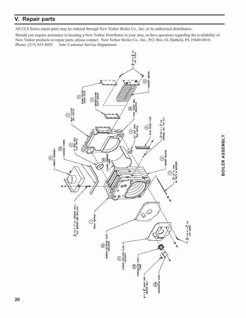
AllCLSSeriesrepairpartsmaybeorderedthroughNewYorkerBoilerCo.,Inc.oritsauthorizeddistributors.ShouldyourequireassistanceinlocatingaNewYorkerDistributorinyourarea,orhavequestionsregardingtheavailabilityofNewYorkerproductsorrepairparts,pleasecontact:NewYorkerBoilerCo.,Inc.,P.O.Box10,Hatfield,PA19440-0010,Phone:(215)855-8055Attn:CustomerServiceDepartment
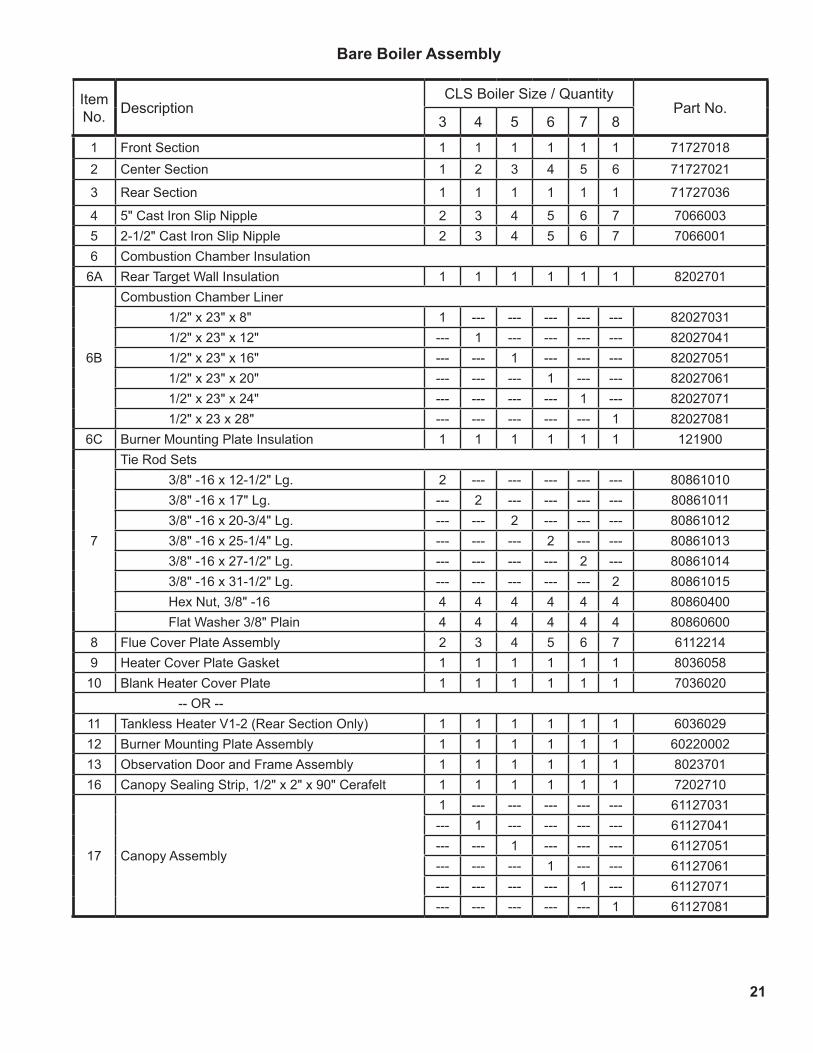
V. Repair parts
BO
ILE
R A
SS
EM
BLY
21
Item No. Description
CLS Boiler Size / QuantityPart No.
3 4 5 6 7 8
1 Front Section 1 1 1 1 1 1 717270182 Center Section 1 2 3 4 5 6 71727021
3 Rear Section 1 1 1 1 1 1 71727036
4 5" Cast Iron Slip Nipple 2 3 4 5 6 7 70660035 2-1/2" Cast Iron Slip Nipple 2 3 4 5 6 7 70660016 Combustion Chamber Insulation
6A Rear Target Wall Insulation 1 1 1 1 1 1 8202701
6B
Combustion Chamber Liner 1/2" x 23" x 8" 1 --- --- --- --- --- 82027031 1/2" x 23" x 12" --- 1 --- --- --- --- 82027041 1/2" x 23" x 16" --- --- 1 --- --- --- 82027051 1/2" x 23" x 20" --- --- --- 1 --- --- 82027061 1/2" x 23" x 24" --- --- --- --- 1 --- 82027071 1/2" x 23 x 28" --- --- --- --- --- 1 82027081
6C Burner Mounting Plate Insulation 1 1 1 1 1 1 121900
7
Tie Rod Sets 3/8" -16 x 12-1/2" Lg. 2 --- --- --- --- --- 80861010 3/8" -16 x 17" Lg. --- 2 --- --- --- --- 80861011 3/8" -16 x 20-3/4" Lg. --- --- 2 --- --- --- 80861012 3/8" -16 x 25-1/4" Lg. --- --- --- 2 --- --- 80861013 3/8" -16 x 27-1/2" Lg. --- --- --- --- 2 --- 80861014 3/8" -16 x 31-1/2" Lg. --- --- --- --- --- 2 80861015 Hex Nut, 3/8" -16 4 4 4 4 4 4 80860400 Flat Washer 3/8" Plain 4 4 4 4 4 4 80860600
8 Flue Cover Plate Assembly 2 3 4 5 6 7 61122149 Heater Cover Plate Gasket 1 1 1 1 1 1 8036058
10 Blank Heater Cover Plate 1 1 1 1 1 1 7036020 -- OR --
11 Tankless Heater V1-2 (Rear Section Only) 1 1 1 1 1 1 603602912 Burner Mounting Plate Assembly 1 1 1 1 1 1 6022000213 Observation Door and Frame Assembly 1 1 1 1 1 1 802370116 Canopy Sealing Strip, 1/2" x 2" x 90" Cerafelt 1 1 1 1 1 1 7202710
17 Canopy Assembly
1 --- --- --- --- --- 61127031--- 1 --- --- --- --- 61127041--- --- 1 --- --- --- 61127051--- --- --- 1 --- --- 61127061--- --- --- --- 1 --- 61127071--- --- --- --- --- 1 61127081
Bare Boiler Assembly
22
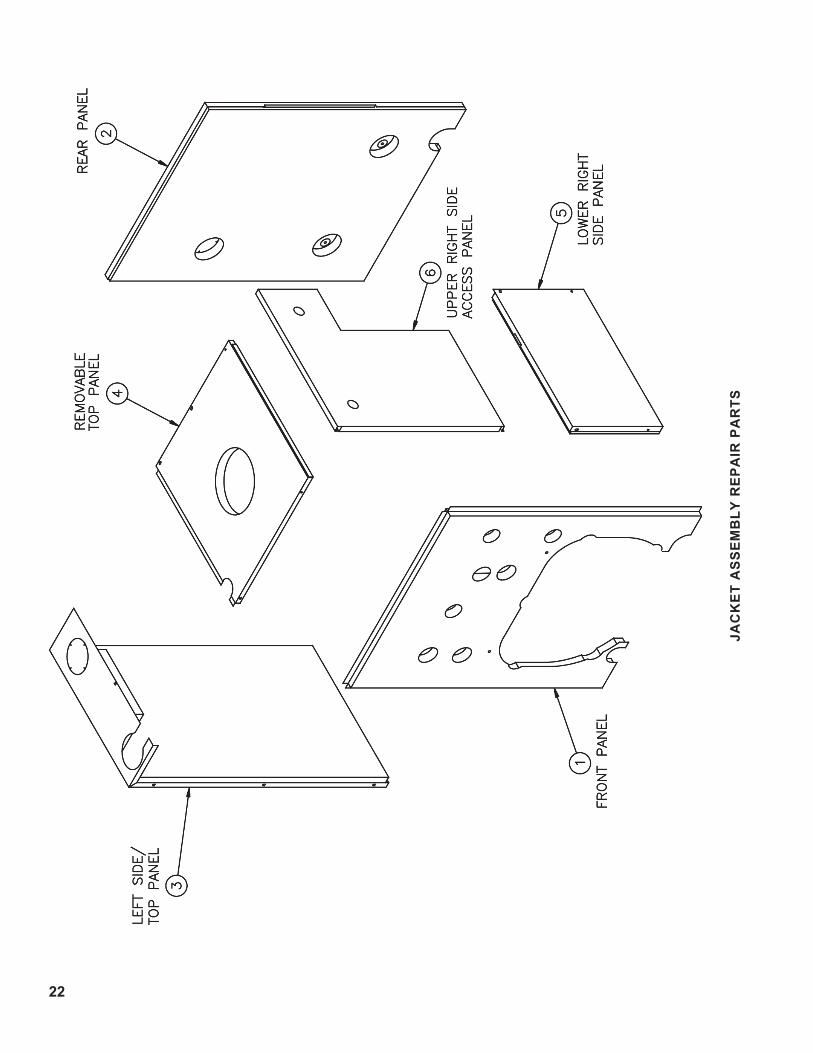
JAC
Ke
T A
SS
eM
BLY
re
PA
Ir P
Ar
TS

23
Item No. Description
CLS Boiler Size / QuantityPart No.
3 4 5 6 7 8
Jacket Components - Items 1 thru 6 Include Insulation As Part of Assembly
1 Jacket Front Panel Assembly 1 1 1 1 1 1 6047303752 Jacket Rear Panel Assembly 1 1 1 1 1 1 604730376
3 Jacket Left Side/Top Panel Assembly
1 --- --- --- --- --- 604730372--- 1 --- --- --- --- 604730472--- --- 1 --- --- --- 604730572--- --- --- 1 --- --- 604730672--- --- --- --- 1 --- 604730772--- --- --- --- --- 1 604730872
4 Jacket Top Panel Assembly
1 --- --- --- --- --- 604730371--- 1 --- --- --- --- 604730471--- --- 1 --- --- --- 604730571--- --- --- 1 --- --- 604730671--- --- --- --- 1 --- 604730771--- --- --- --- --- 1 604730871
5 Jacket Lower Right Side Panel Assembly
1 --- --- --- --- --- 604730374--- 1 --- --- --- --- 604730474--- --- 1 --- --- --- 604730574--- --- --- 1 --- --- 604730674--- --- --- --- 1 --- 604730774--- --- --- --- --- 1 604730874
6 Jacket Upper Right Side Panel Assembly
1 --- --- --- --- --- 604730373--- 1 --- --- --- --- 604730473--- --- 1 --- --- --- 604730573--- --- --- 1 --- --- 604730673--- --- --- --- 1 --- 604730773--- --- --- --- --- 1 604730873
10 Year Limited Steam Warranty Mailer 81460121I=B=R Pamphlet 81460061Honeywell R7184A1000 Protectorelay 80160416Hydrolevel CG450 L.W.C.O. 80160623McDonnell & Miller PS801 L.W.C.O. 80160723Hydrolevel, EL-1214 Probe 80160629Honeywell PA404A1009 Pressuretrol 80160300Honeywell L4006A2015 Aquastat 80160400#123871A Immersion Well ¾" NPT 80160452¼" x 90° Syphon, 2½" Extended Leg 8066030062½" Dia. Steam Gauge 100325-01¾" NPT Drain Valve, Conbraco #31-606 8066030016" Gauge Glass Set, Conbraco #20-104-10 8056091¾" NPT, M/F, 15 PSI Safety Valve Conbraco #13-501-08 81660504

22
By this Warranty Statement New Yorker Boiler Co., Inc. (“New Yorker”) issues limited warranties subject to the terms and conditions stated below. These limited warranties apply to residential cast iron steam boilers labeled with the New Yorker® brand which are sold on or after March 1, 2004
ONE YEAR LIMITED WARRANTYOne Year Limited Warranty for Residential Cast Iron Steam BoilersNew Yorker warrants to the original consumer purchaser at the original installation address that its residential cast iron steam boilers will be free of defects in material and workmanship under normal usage for a period of one year from the date of original installation. In the event that any defect in material or workmanship is found during the one-year period following the date of installation, New Yorker will, at its option, repair the defective part or provide a replacement free of charge, F.O.B. its factory.
TEN YEAR LIMITED WARRANTYTen Year Pressure Vessel Limited Warranty for Residential Cast Iron Steam Boilers New Yorker warrants to the original consumer purchaser at the original installation address that the pressure vessel of its residential cast iron steam boilers will be free of defects in material and workmanship under normal usage for a period of 10 years from the date of original installation. In the event that any defect in material or workmanship is found during the ten year period following the date of installation, New Yorker will, at its option, repair the defective pressure vessel or provide a replacement free of charge, F.O.B. its factory.
EXCEPTIONS AND EXCLUSIONS1. Components Manufactured by Others - following the expiration of
the foregoing one year limited warranty, all component parts of a boiler which are manufactured by others (such as burners, burner controls, circulator, tankless water heater, and New Yorker Link) shall be subject only to the manufacturer’s warranty, if any.
2. Removal and Replacement Costs - these warranties do not cover expenses of removal or reinstallation. The consumer purchaser will be responsible for the cost of removing and replacing any defective part and all labor and related materials connected therewith. Replacement parts will be invoiced to the distributor in the usual manner and will be subject to adjustment upon proof of defect.
3. Proper Installation - these warranties are conditioned upon the installation of the boiler in strict compliance with New Yorker’s Installation, Operating and Service Instructions. New Yorker specifically disclaims any liability of any kind which arises from or relates to improper installation.
4. Improper Use or Maintenance - these warranties will not be applicable if the boiler is used or operated over its rated capacity, is installed for uses other than home heating, or is not maintained in accordance with New Yorker’s Installation, Operating and Service Instructions and hydronics industry standards.
5. Improper Operation - these warranties will not be applicable if theboiler has been damaged as a result of being improperly serviced or operated, including but not limited to the following: operated with insufficient water; allowed to freeze; subjected to flood conditions; or operated with water conditions and/or fuels or additives which cause unusual deposits or corrosion in or on the pressure vessel or associated controls.
6. Geographic Limitations - these warranties apply only to boilers installed within the 48 contiguous United States.
7. Installation Requirements - in order for these warranties to be effective:a) The boiler must be installed in a single or two-family residential dwelling. This warranty does not apply to boilers installed in apartments or for commercial or industrial applications.b) The boiler must be installed in strict compliance with New Yorker’s Installation, Operating and Service Instructions, including the installation of a low water cut-off, by an installer regularly engaged in boiler installations.
c) Boiler sections must not have been damaged during shipment or installation.
d) The boiler must be vented in accordance with chimney recommendations set forth in New Yorker’s Installation, Operating and Service Instructions.
8. Exclusive Remedy New Yorker’s obligation in the event of anybreach of these warranties is expressly limited to the repair or replacement of any part found to be defective under conditions of normal use.
9. Limitation of Damages Under no circumstances will New Yorker be liable for incidental, indirect, special or consequential damages of any kind under these warranties, including, without limitation, injury or damage to persons or property and damages for loss of use, inconvenience or loss of time. New Yorker’s liability under these warranties shall under no circumstances exceed the purchase price paid for the boiler involved. Some states do not allow the exclusion or limitation of incidental or consequential damages, so the above limitation or exclusion may not apply to you.
10. Limitation of Warranty - these limited warranties are given in lieu of all other express warranties and set forth the entire obligation of New Yorker with respect to any defect in a residential cast iron steam boiler. New Yorker shall have no express obligations, responsibilities or liabilities of any kind, other than those set forth herein.
ALL APPLICABLE IMPLIED WARRANTIES, IF ANY, INCLUDING ANY WARRANTY OF MERCHANTABILITY OR FITNESS FOR PARTICULAR PURPOSE, ARE EXPRESSLY LIMITED IN DURATION TO A PERIOD OF ONE YEAR, EXCEPT THAT IMPLIED WARRANTIES, IF ANY, APPLICABLE TO THE PRESSER VESSEL OF A RESIDENTIAL CAST IRON STEAM BOILER SHALL BE LIMITED IN DURATION TO THE LESSER OF THE DURATION OF SUCH IMPLIED WARRANTY OR A PERIOD OF TEN YEARS.
Some states do not allow limitations on how long an implied warranty lasts, so the above limitation may not apply to you
PROCEDURE FOR OBTAINING WARRANTY SERVICEUpon discovery of a condition believed to be related to a defect in material or workmanship covered by these warranties, the original consumer purchaser should notify the installer, who will in turn notify the distributor. If this action is not possible or does not produce a prompt response, the original consumer purchaser should write to New Yorker Boiler Co., Inc. at P.O. Box 10, Hatfield, PA 19440-0010, giving full particulars in support of the claim.The original consumer purchaser is required to make available for inspection by New Yorker or its representative the parts claimed to be defective and, if requested by New Yorker, to ship those parts prepaid to New Yorker at the above address for inspection or repair. In addition, the original consumer purchaser agrees to make all reasonable efforts to settle any disagreement arising in connection with any warranty claim before resorting to legal remedies in the courts.
THIS WARRANTY GIVES YOU SPECIFIC LEGAL RIGHTS AND YOU MAY ALSO HAVE OTHER RIGHTS WHICH VARY FROM STATE TO STATE.
NEW YORKER BOILER CO., INC.
Limited WarrantiesFor Residential Cast Iron Steam Boilers