installation manual for lg air handler unit (ahu
TRANSCRIPT

INSTALLATION MANUAL FOR LG AIR HANDLER UNIT (AHU)
COMMUNICATIONS KIT
AHU Model Number: PAHCMS000

For continual product development, LG Electronics U.S.A., Inc. reserves the right to change specifications without notice. © LG Electronics U.S.A., Inc.
PROPRIETARY DATA NOTICEThis document, as well as all reports, illustrations, data, information, and other materials are the property of
LG Electronics U.S.A., Inc., and are disclosed by LG Electronics U.S.A., Inc. only in confidence.
For more materials such as submittals, catalogs, engineering, installation, owner’s, and service manuals, visit www.lghvac.com.
Do not throw away, destroy, or lose this manual. Please read carefully and store in a safe place for future reference.
Content familiarity required for proper installation.
The instructions included in this manual must be followed to prevent product malfunction, property damage, injury, or death to the user or other people. Incorrect operation due to ignoring any instructions will cause harm or damage. The level of seriousness is classified by the symbols described by the summary list of safety precautions on page 3.

3Due to our policy of continuous product innovation, some specifications may change without notification. ©LG Electronics U.S.A., Inc., Englewood Cliffs, NJ. All rights reserved. “LG” is a registered trademark of LG Corp.
TABLE OF CONTENTS
Safety Precautions ..........................................................................................................................................................................4
AHU Kit Introduction .......................................................................................................................................................................7
Specifications, Components List ...................................................................................................................................................8
AHU Communications Kit Installation ...........................................................................................................................................9Selecting the Best Location �����������������������������������������������������������������������������������������������������������������������������������������������������������9DIP Switch Settings ���������������������������������������������������������������������������������������������������������������������������������������������������������������������10AHU Communications Kit Parts ��������������������������������������������������������������������������������������������������������������������������������������������������13AHU Communications Kit Mounting �������������������������������������������������������������������������������������������������������������������������������������������14Power Wiring ������������������������������������������������������������������������������������������������������������������������������������������������������������������������������18Communications Wiring ���������������������������������������������������������������������������������������������������������������������������������������������������������������19Controller Settings �����������������������������������������������������������������������������������������������������������������������������������������������������������������������20Solutions Overview ����������������������������������������������������������������������������������������������������������������������������������������������������������������������24Main Module Settings ������������������������������������������������������������������������������������������������������������������������������������������������������������������27Communication Module ���������������������������������������������������������������������������������������������������������������������������������������������������������������31Defrost Setting �����������������������������������������������������������������������������������������������������������������������������������������������������������������������������32External Connection Diagrams ����������������������������������������������������������������������������������������������������������������������������������������������������33Discharge Air Temperature Controller ������������������������������������������������������������������������������������������������������������������������������������������37
EEV Kit Installation ........................................................................................................................................................................45Introduction, Specifications, and Design Parameters ������������������������������������������������������������������������������������������������������������������45EEV Kit Parts ������������������������������������������������������������������������������������������������������������������������������������������������������������������������������46Mounting the EEV Kit ������������������������������������������������������������������������������������������������������������������������������������������������������������������48Preparing the Pipes ���������������������������������������������������������������������������������������������������������������������������������������������������������������������49Brazing and Insulating the Piping ������������������������������������������������������������������������������������������������������������������������������������������������50PRLK048A0 and PRLK096A0 Wiring ������������������������������������������������������������������������������������������������������������������������������������������51PRLK396A0 Wiring ����������������������������������������������������������������������������������������������������������������������������������������������������������������������52Control Functions ������������������������������������������������������������������������������������������������������������������������������������������������������������������������53
Testing ............................................................................................................................................................................................57
Troubleshooting ............................................................................................................................................................................58

4
PRDC
AM A
HU C
omm
unic
atio
n Ki
t Ins
talla
tion
Man
ual
Due to our policy of continuous product innovation, some specifications may change without notification. ©LG Electronics U.S.A., Inc., Englewood Cliffs, NJ. All rights reserved. “LG” is a registered trademark of LG Corp.
TABLE OF SYMBOLSThis symbol indicates an imminently hazardous situation which, if not avoided, will result in death or serious injury�
This symbol indicates a potentially hazardous situation which, if not avoided, could result in death or serious injury�
This symbol indicates a potentially hazardous situation which, if not avoided, may result in minor or moderate injury�
This symbol indicates situations that may result in equipment or property damage accidents only�
This symbol indicates an action should not be completed�
DANGER
CAUTION
The instructions below must be followed to prevent product malfunction, property damage, injury or death to the user or other people. Incor-rect operation due to ignoring any instructions will cause harm or damage. The level of seriousness is classified by the symbols described below.
Installation
All electrical work must be performed by a licensed electri-cian and conform to local building codes or, in the absence of local codes, with the National Electrical Code, and the instructions given in this manual.If the power source capacity is inadequate or the electric work is not performed properly, it may result in fire, electric shock, physical injury or death�
Do not touch the communications and EEV kits’ wir-ing, terminals, or other electrical components with tools or exposed skin when the power is connected. Only qualified technicians should install, remove, or re-install the kits.Improper installation or use may result in fire, electric shock, physical injury or death�
Do not install, remove, or re-install the communications and EEV kits by yourself (end user). Ask the dealer or a qual-ified technician familiar with safety procedures and equipped with the proper tools and test instruments to install the kits.Improper installation by the user may result in fire, electric shock, physi-cal injury or death�
For replacement of an installed communications and EEV kits, always contact a qualified LG service provider familiar with safety procedures and equipped with the proper tools and test instruments.There is risk of fire, electric shock, and physical injury or death.
Do not install the communications and EEV kits in a loca-tion where the kits can be exposed to rain, snow, etc.There is risk of physical injury or death due to electric shock�
Safely dispose of the packing materials.Tear apart and throw away plastic packaging bags so that children may not play with them and risk suffocation and death�
Wear protective gloves when unpacking, installing, and han-dling the kits. Sharp edges may cause personal injury.
Do not install the communications and EEV kits in loca-tions where either kit could fall down.There is risk of physical injury�
Use the appropriate parts and connectors. There is risk of physical injury or death due to fire and / or electric shock.
Replace all control box and panel covers on the communica-tions and EEV kits.If cover panels are not installed securely, dust, water, and animals may enter the kits, causing fire, electric shock, and physical injury or death.
Failure to carefully read and follow all instructions in this manual can result in physical injury or death.
Only qualified technicians familiar with safety procedures and equipped with the proper tools and test instruments should install, remove, or re-install the communications and EEV kits.Improper installation or use may result in product malfunction�
Do not install the communications and EEV kits in a location where the kits can be exposed to rain, snow, etc.There is risk of product malfunction�
Do not drop the communications and EEV kits.It may damage the products�
Failure to carefully read and follow all instructions in this manual can result in property damage and equipment mal-function.
SAFETY PRECAUTIONS

5
Safety Precautions
Due to our policy of continuous product innovation, some specifications may change without notification. ©LG Electronics U.S.A., Inc., Englewood Cliffs, NJ. All rights reserved. “LG” is a registered trademark of LG Corp.
SAFETY PRECAUTIONS
Do not supply power to the communication and EEV kits until all electrical wiring, controls wiring, piping, installation, and refrigerant evacuation are completed for the whole air conditioning system.
The information contained in this manual is intended for use by an industry-qualified, experienced, certified electrician familiar with the U.S. National Electric Code (NEC) who is equipped with the proper tools and test instruments.Failure to carefully read and follow all instructions in this manual can result in equipment malfunction or property damage�
The information contained in this manual is intended for use by an industry-qualified, experienced, certified electrician familiar with the U.S. National Electric Code (NEC) who is equipped with the proper tools and test instruments.Failure to carefully read and follow all instructions in this manual can result in personal injury or death�
All electric work must be performed by a licensed electrician and conform to local building codes or, in the absence of local codes, with the National Electrical Code, and the instructions given in this manual. If the power source capacity is inadequate or the electric work is not performed properly, it may result in fire, electric shock, physical injury or death�
Refer to local, state, and federal codes, and use power wires of sufficient current capacity and rating.Wires that are too small may generate heat and cause a fire and physi-cal injury or death�
Secure all field wiring connections with appropriate wire strain relief.Improperly securing wires will create undue stress on equipment power lugs. Inadequate connections may generate heat, cause a fire and physical injury or death�
Verify that all power wiring, plugs, and sockets are not loose or damaged.Loose wiring may overheat at connection points, causing a fire, electrical shock, physical injury or death�
WIRINGDANGER
High voltage electricity is required to operate the commu-nications and EEV kits. Adhere to the NEC code and these instructions when wiring. Improper connections and inadequate grounding can cause accidental injury or death�
Always ground the communications and EEV kits following local, state, and NEC codes.There is risk of fire, electric shock, and physical injury or death.
Turn the power off at the nearest disconnect before servicing the equipment.Electrical shock can cause physical injury or death�
Properly size all circuit breakers or fuses.There is risk of fire, electric shock, explosion, physical injury or death.
Communication kit requires its own power source (EEV kit is powered off of Communication kit). Do not share the power source with other equipment.There is risk of heat generation which may cause fire, electric shock, explosion, physical injury or death�

6
PRDC
AM A
HU C
omm
unic
atio
n Ki
t Ins
talla
tion
Man
ual
Due to our policy of continuous product innovation, some specifications may change without notification. ©LG Electronics U.S.A., Inc., Englewood Cliffs, NJ. All rights reserved. “LG” is a registered trademark of LG Corp.
Do not install the communications and EEV kits in loca-tions exposed to open flame or extreme heat. Do not touch the kits with wet hands.There is risk of fire, electric shock, physical injury or death.
Do not modify or extend the power supply cords.There is risk of fire, electric shock, physical injury or death.
Do not step or place anything on the communications and EEV kits.If the product falls, there is risk of physical injury�
Do not place heavy objects on the communications and EEV kits’ power cables.There is risk of fire, electric shock, physical injury or death.
Only authorized persons should operate the communications and EEV kits.If the kits are not operated properly, there is a risk of physical injury�
Do not provide power to or operate communication and EEV kits if the kits are flooded or submerged. Always have the dealer or an authorized technician to service the kits.There is risk of fire, electric shock, physical injury or death.
Do not store or use flammable gas or combustibles near the communications and EEV kits.There is risk of fire, explosion, and physical injury or death.
Unplug the communication and EEV kits if either kit emits strange sounds, smells, or smoke.There is risk of fire, electric shock, physical injury or death.
Do not let the communication and EEV kits get wet.There is risk of product failure or malfunction�
Only authorized persons should operate the communication and EEV kits.There is risk of product failure or malfunction�
Do not drop the communications and EEV kits.There is risk of product failure or malfunction�
Do not step or place anything on the communications and EEV kits.If the product falls, there is risk of product damage�
OPERATIONDANGER
CAUTION
SAFETY PRECAUTIONS
7
General Specifications
Due to our policy of continuous product innovation, some specifications may change without notification. ©LG Electronics U.S.A., Inc., Englewood Cliffs, NJ. All rights reserved. “LG” is a registered trademark of LG Corp.
AHU KIT INTRODUCTION
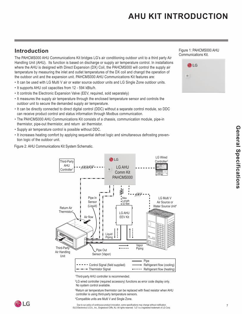
Figure 1: PAHCMS000 AHU Communications Kit.
Figure 2: AHU Communications Kit System Schematic.
IntroductionThe PAHCMS000 AHU Communications Kit bridges LG’s air conditioning outdoor unit to a third party Air Handling Unit (AHU). Its function is based on discharge or supply air temperature control. In installations where the AHU is designed with Direct Expansion (DX) Coil, the PAHCMS000 will control the supply air temperature by measuring the inlet and outlet temperatures of the DX coil and changd the operation of the outdoor unit and the expansion unit. PAHCMS000 AHU Communications Kit features are:• It can be used with LG Multi V air or water source outdoor units and LG Single Zone outdoor units.• It supports AHU coil capacities from 12 - 594 kBtu/h.• It controls the Electronic Expansion Valve (EEV, required, sold separately)• It measures the supply air temperature through the enclosed temperature sensor and controls the
outdoor unit to secure the demanded supply air temperature.• It can be directly connected to direct digital control (DDC) without a separate control module, so DDC
can receive product control and status information through Modbus communication.• The PAHCMS000 AHU Communications Kit consists of a chassis, communication module, pipe-in
thermistor, pipe-out thermistor, and return air thermistor.• Supply air temperature control is possible without DDC.• It increases heating comfort by applying sequential defrost logic and simultaneous defrosting preven-
tion logic of the outdoor unit.
Control Signal (field supplied)Pipe
Thermistor SignalRefrigerant flow (cooling)Refrigerant flow (heating)
LG WiredController2Third-Party
AHUController1
Air flowLG AHUEEV Kit
Third-PartyAir Handling
Unit
LG Multi VAir Source or
Water Source Unit4
1Third-party AHU controller is recommended.2LG wired controller (required accessory) functions as error code display only. No system control available.3Return air temperature thermistor can be replaced with fixed resistor when AHU controller is using third-party temperature sensors.4Compatible units are Multi V and Single Zone.
Return AirThermistor3
MaxLength32 feet
LG AHUComm Kit
PAHCMS000
Vapor Piping
Liquid Piping
Pipe OutSensor (Vapor)
Pipe InSensor(Liquid)

8
PRDC
AM A
HU C
omm
unic
atio
n Ki
t Ins
talla
tion
Man
ual
Due to our policy of continuous product innovation, some specifications may change without notification. ©LG Electronics U.S.A., Inc., Englewood Cliffs, NJ. All rights reserved. “LG” is a registered trademark of LG Corp.
SpecificationsTable 1: PAHCMS000 AHU Communications Kit Specifications Table.
AHU Communications Kit ComponentsTable 2: PAHCMS000 AHU Communications Kit Components Table (factory supplied).
Kit Model Number PAHCMS000For Use With Multi V and Single Zone
Power Supply Requirements 208-230VAC, 60Hz, 1PhRated Current 0.1A
Ambient Operating Temperature Range -4 to +149°FAmbient Operating Humidity Range 0 to 98% (Non-condensing)
Dimensions (in., W x H x D) 14-31/32” W x 6-3/32” H x 11-13/16” DNet Weight (lbs.) 16.5
Shipping Weight (lbs.) 19.4Communications RS-485 (4 wires required: 2 connect to IDU A/B terminals and 2 connect to UI4/G terminals on ODU)
Communications Cable AWG 18 x 4 Stranded, Shielded Copper Cable
Part Quantity Image
AHU Communications Kit One (1)
Return Air (Room)Thermistor One (1)
Pipe ThermistorTwo (2)
(One [1] Pipe In,One [1] Pipe Out)
AHU COMMUNICATIONS KIT SPECIFICATIONS, COMPONENTS LIST

9
Installation
Due to our policy of continuous product innovation, some specifications may change without notification. ©LG Electronics U.S.A., Inc., Englewood Cliffs, NJ. All rights reserved. “LG” is a registered trademark of LG Corp.
AHU Communications Kit Design Parameters• Minimum coil entering air temperature is 41°F when system is operating in heating mode.• AHU coil sizing parameters:
• Suction (evaporating) temperature for coil sizing is 41°F, Condensing (liquid) temperature for coil sizing is 110°F.• Recommended coil tube sizes: 3/8 or 1/2 inches.• Coil volume is needed to calculate additional refrigerant charge amount.• Coils larger than 16 tons should be divided into multiple circuits to allow EEV Kit connection kit (EEV Kit sold separately).
• Pipe sizing rules are same rules as the connected air-source or water-source heat pump (see respective Engineering and Installation Manuals for more information).
• Maximum recommended combination ratio is 100%.• AHU Communications Kits and EEV Kits (sold separately) are not weatherproof and must be protected from rain, snow, etc.
AHU COMMUNICATIONS KIT INSTALLATIONSelecting the Best Location
AHU Operation RangeRange of the heat exchanger inlet air temperature is 64.4 to 104°F for cooling, and 41 to 86°F for heating. If the temperature is <64.4°F for cooling and >86°F for heating, the system might cycle on and off because of the system’s protection logic.
Application Condition100% outside air intake: The AHU(s) is (are) the only indoor unit(s)
connected to the air-source / water-source heat pump unit(s).The total capacity of 100% outside air intake AHU(s) should be50~100% of the air-source / water-source heat pump.
To measure room temperature accurately, install the room thermistor in the heat exchanger inlet� If the room thermistor is not installed properly, the AHU may not operate properly. Room thermistor can be replaced with fixed resistor when using a third-party AHU controller.
Table 3: AHU Application and Condition.
Selecting the Best LocationDo• Install the AHU Communications and EEV Kits with the access panels facing outward.• Install in a location that can support the weight of the kits.• Install the EEV kit on the AHU as close as possible to the heat exchanger.
Don’t• Don’t install or operate the unit in an area where mineral oils, sulphuric gases, acidic or alkaline vapors or spray are present.• Don’t install in an area where the air contains high levels of salt (oceanside locations).• Don’t install in vehicles or vessels.• Don’t install in an area where voltage fluctuates significantly (factories), or near machines that generate electromagnetic waves.

10
PRDC
AM A
HU C
omm
unic
atio
n Ki
t Ins
talla
tion
Man
ual
Due to our policy of continuous product innovation, some specifications may change without notification. ©LG Electronics U.S.A., Inc., Englewood Cliffs, NJ. All rights reserved. “LG” is a registered trademark of LG Corp.
Communication ModuleMain ModuleThe default setting of all DIP switches is “off”
etoNgnitteSmetIoNeman W/S
SW1
1 Control TypeOn Communication Controlled by DDC through Modbus or LG centralized controller
Off Contact signal Controlled by DDC through Contact signal AI and DILG Centralized controller can only monitor status
2 Discharge Temp.Control Type
On Stand alone Discharge temp. control by LG controller using own dischargetemp. sensor
Off Manual by DDC Discharge temp. control by DDC using filed supplied dischargetemp. sensor
3 Defrost OperationType¹
On Normal In case of multiple outdoor units, Defrost operation can be oper-ated simultaneously
Off SequentialStart up
In case of multiple outdoor units, the outdoor unit is sequentiallystarted at intervals of 10 minutes
4Central
CommunicationType
On LG Central Comm Modbus Communication
Off - Not Used
SW2
1 ODU CapacityControl
On ODU CapacitySetting #2 ODU capacity control #2
Off ODU CapacitySetting #1 ODU capacity control #1
---devreseR2---devreseR3---devreseR4
SW3
---devreseR1---devreseR2---devreseR3---devreseR4
SW4
---devreseR1---devreseR2---devreseR3---devreseR4
Note:1. Function of defrost operation type can be applied only to Multi V outdoor units (after MULTI V 5 model).
Figure 3: Main Module DIP Switches.
Table 4: Main Module DIP Switch Settings
AHU COMMUNICATIONS KIT INSTALLATIONDIP Switch Settings

11
Installation
Due to our policy of continuous product innovation, some specifications may change without notification. ©LG Electronics U.S.A., Inc., Englewood Cliffs, NJ. All rights reserved. “LG” is a registered trademark of LG Corp.
AHU COMMUNICATIONS KIT INSTALLATIONDIP Switch Settings
Communication ModuleMain ModuleThe default setting of all dip switch is set “off”
Note :1. Do not change the settings of reserved switches. Changing these settings can result in equipment malfunction.
etoNgnitteSmetIoNeman W/S
SW1
1 ODU TypeOn Single Comm Using Single Split outdoor unitOff MULTI V Comm Using MULTI V outdoor unit
2 Control TypeOn Communication Controlled by Modbus between modulesOff Contact signal Not used
3 DO TypeOn Fan Speed Not usedOff Status Not used
4 Fan Speed(TH. On/Off)
On Fixed Not usedOff Change Not used
SW2
---devreseR1---devreseR2
3/4 UI Setting
Off/Off UI Setting #1 Not usedOff/On UI Setting #2 Not used
--ffO/nO--nO/nO
SW3
1 Master/SlaveOn Slave mode Not usedOff Master mode Master is default
2/3 Operation modesetting
Off/Off Heat Pump Cooling or Heating operation mode is availableOff/On Heating Only Operation mode is Heating only (Heating / Ventilation)On/Off Cooling Only Operation mode is Cooling only (Cooling / Ventilation )
-devreseRnO/nO---devreseR4
SW4 1~4 Capacity IndexSetting - - According to ODU Type, you can setup the capacity index of
MULTI V or Single Split
Figure 4: Communications Module DIP Switches.
Table 5: Communications Module DIP Switch Settings

12
PRDC
AM A
HU C
omm
unic
atio
n Ki
t Ins
talla
tion
Man
ual
Due to our policy of continuous product innovation, some specifications may change without notification. ©LG Electronics U.S.A., Inc., Englewood Cliffs, NJ. All rights reserved. “LG” is a registered trademark of LG Corp.
AHU COMMUNICATIONS KIT INSTALLATIONDIP Switch Settings
Table 6: SW4 DIP Switch Settings for AHU Capacity
SW4 DIP switchesCapacity (kBTU/h)
MULTI V
5211
7512
9813
21424
51825
81636
42247
03848
63459
246701
846911
0651121
0743131
5835141
devreseR27151
devreseR29161
Single ZoneSwitch
Number
Notes:1. PAHCMS000 AHU can be connected to the PRLK048A0, PRLK096A0, or PRLK396A0 EEV kits only.2. If connecting the PRLK396A0 EEV kit to a Multi V outdoor unit, set DIP switches 1, 2, 3, and 4 to ON to set capacity to 192 kBtu/h.

13
Installation
Due to our policy of continuous product innovation, some specifications may change without notification. ©LG Electronics U.S.A., Inc., Englewood Cliffs, NJ. All rights reserved. “LG” is a registered trademark of LG Corp.
1
2
4
6
3
5
AHU COMMUNICATIONS KIT INSTALLATIONAHU Communications Kit Parts
Figure 5: AHU Communications Kit Parts Diagram.
Table 7: AHU Communications Kit Parts Table.
Diagram Label Part Name Quantity1 Thermistor Assembly, NTC Three (3)2 Harness, Multi One (1)3 Main Module One (1)4 Communications Module One (1)5 Bracket One (1)6 Panel Assembly, Control Three (3)

14
PRDC
AM A
HU C
omm
unic
atio
n Ki
t Ins
talla
tion
Man
ual
Due to our policy of continuous product innovation, some specifications may change without notification. ©LG Electronics U.S.A., Inc., Englewood Cliffs, NJ. All rights reserved. “LG” is a registered trademark of LG Corp.
1. Use the key to open the AHU Communication Kit door.
2. Remove the four nuts from the four captive bolts at the corners of the control panel assembly.
3. Carefully remove the control panel assembly from the AHU Communication Kit.
4. Use the AHU Communication Kit as a template and mark the locations of the screw holes on the mounting surface.NOTE: Do not drill holes without removing the control panel assembly.Metal shavings can collect on the control panel assembly and damage the equipment when power is applied�
5. Drill the four holes for the field-supplied screws. Ensure the drill bit does not damage any equipment or components.
6. Carefully replace the control panel assembly and secure with the four nuts on the four captive bolts.
7. Position the AHU Communications Kit at the mounting location and secure with four field-supplied screws. Ensure the screws do not damage any equipment or components.
Figure 6: AHU Communications Kit Installation
AHU COMMUNICATIONS KIT INSTALLATIONAHU Communications Kit Mounting
Model
PAHCMS000 14 31/32 6-3/32 11-13/16 13-2/5 10-1/4
11/32 Holes (4)
BackFrontSide
Size (inch)W D H A B
D W A
BH

15
Installation
Due to our policy of continuous product innovation, some specifications may change without notification. ©LG Electronics U.S.A., Inc., Englewood Cliffs, NJ. All rights reserved. “LG” is a registered trademark of LG Corp.
AHU COMMUNICATIONS KIT INSTALLATIONWiring Diagram
Figure 7: AHU Communications Kit Wiring Diagram
Ther
mis
tor
Ret
urn

16
PRDC
AM A
HU C
omm
unic
atio
n Ki
t Ins
talla
tion
Man
ual
Due to our policy of continuous product innovation, some specifications may change without notification. ©LG Electronics U.S.A., Inc., Englewood Cliffs, NJ. All rights reserved. “LG” is a registered trademark of LG Corp.
AHU COMMUNICATIONS KIT INSTALLATIONWiring Diagram
*DI is available when Dip SW1-1 is Off
Name PortValue
Electrical Spec FunctionShort Open
On/Off DI1 On Off Non voltage Operation On/OffCool/Heat DI2 Heating Cooling Non voltage Operation Mode
Emer. Stop DI3 Emergency Stop Normal Non voltage Emergency Stop Input (Priority operation)
noitcnuF.cepS lacirtcelEeulaVtroPemaN
Alarm DO1 30 VDC / 5 A250 VAC / 5 A
Output normal or error status (Relay C Contact)
- A Contact Normal status : openError status : short
- B ContactNormal status : shortError status : open
-Normal Status
A B COM
-Error Status
A B COM
noitcnuF.cepS lacirtcelEmetItroPemaN
ODU Comm. RS485 CH2ODU Comm.(CEN A/B or
INT A/B)
Max 3280 ft,2C x 18~16 AWG
(shield wire)
Communication with MULTI V/Singlesplit ODU for ODU Capacity control
LGCentral Comm. RS485 CH3 LG Central Comm.
Max 1640 ft,2C x 18~16 AWG
(shield wire)
Communication with LG centralizedcontroller through LGAP Protocol
DDC CentralComm. RS485 CH4 DDC(Modbus)
Central Comm.
Max 1640 ft,2C x 18~16 AWG
(shield wire)
Communication with DDC central-ized controller through Modbus pro-tocol
Table 8: RS485 Communication Port
Table 9: Digital Input
Table 10: Digital Output – Relay C Contact

17
Installation
Due to our policy of continuous product innovation, some specifications may change without notification. ©LG Electronics U.S.A., Inc., Englewood Cliffs, NJ. All rights reserved. “LG” is a registered trademark of LG Corp.
AHU COMMUNICATIONS KIT INSTALLATIONWiring Diagram
Name PortValue
noitcnuF.cepS lacirtcelEShort Open
On/Off DO2 On Off
12 VDC / 1 A,250 VAC / 3 A
Operation On/Off statussutats tsorfeD UDOlamroNtsorfeD3ODtsorfeD
sutats ffO/nO noitarepo rosserpmoCffOnO4ODsutatS .pmoC---5ODdevreseR---6ODdevreseR
noitcnuF.cepS lacirtcelEeulaVtroPemaN---1IUdevreseR---2IUdevreseR---3IUdevreseR---4IUdevreseR---5IUdevreseR---6IUdevreseR
Capacity Control¹0~10V
UI7(AI) 0~10 V Input DC 0~10 V,
20 mA
ODU Capacity control input(0~10 V)*When Temp. Control Type is ‘Manual byDDC’(SW 1-2 : Off), refer to UI7 Analog Input
---8IUdevreseR
1. Refer to the Capacity Control (UI7) combination ratio table.2. UI is available when Dip SW1-1 is Off
Table 11: Digital Output
Table 12: Universal Input

18
PRDC
AM A
HU C
omm
unic
atio
n Ki
t Ins
talla
tion
Man
ual
Due to our policy of continuous product innovation, some specifications may change without notification. ©LG Electronics U.S.A., Inc., Englewood Cliffs, NJ. All rights reserved. “LG” is a registered trademark of LG Corp.
Power Wiring
AHU COMMUNICATIONS KIT INSTALLATION
Figure 8: Power Wiring Connection.
General Power Wiring Guidelines
All electrical work must be performed by a licensed electrician and conform to local building codes or, in the absence of local codes, with the National Electrical Code, and the instructions in this manual.Inadequate power source capacity or improper electric work may result in fire, electric shock, physical injury or death.
All field-supplied parts, materials, and electric work must be conform to local codes.Improper components and installation may result in fire, electric shock, physical injury or death.
A main switch or disconnect, in accordance with relevant local and national codes, and having a contact separation in all poles, must be incorporated in the wiring.Improper installation by the user may result in fire, electric shock, physical injury or death.
Refer to the air-source / water-source heat pump unit installation manual for power wiring sizes, circuit breaker and switch capacities, and wiring instructions. If the power source capacity for the air-source unit / water-source unit is inadequate or the electric work is not performed properly, it may result in fire, electric shock, physical injury or death.
Use copper wire only and connect wires tightly to the terminals. Install wiring so that other equipment is not obstructed. Improper or incomplete connections could result in overheating, fire, electric shock, physical injury or death.
Ensure the power source is disconnected before performing this procedure. If the power source is connected during this procedure, it could result in electric shock, physical injury, or death�
1. Carefully pull the power cable through the cable nut and grommet.
2. Connect the power cable to the power terminal block.
3. Pull enough cable through the nut and grommet to allow enough slack for strain relief.
4. Tighten the cable nut.Front View with Cover Open
Power Terminal Block
CableInsert

19
Installation
Due to our policy of continuous product innovation, some specifications may change without notification. ©LG Electronics U.S.A., Inc., Englewood Cliffs, NJ. All rights reserved. “LG” is a registered trademark of LG Corp.
AHU COMMUNICATIONS KIT INSTALLATIONCommunications Wiring
• Communications wiring must be 18 gauge, shielded, and stranded�
• The thermistor cable, remote controller wires, and communications wires should be positioned at least two (2) inches away from pow-er supply wires� If these wires are installed too closed together, it may result in product malfunction due to electrical interference�
All electrical work must be performed by a licensed electrician and conform to local building codes or, in the absence of local codes, with the National Electrical Code, and the instructions in this manual.If the electrical work is not performed properly, it may result in fire, electric shock, physical injury or death.
All field-supplied parts, materials, and electric work must be conform to local codes.Improper components and installation may result in fire, electric shock, physical injury or death.
Ensure the power source is disconnected before performing this procedure. If the power source is connected during this procedure, it could result in electric shock, physical injury, or death�
1. Carefully pull the communications cable through the cable nut and grommet.
2. Refer to the wiring diagram in Figure 6 and connect the communications cable to the power terminal block.
3. Pull enough cable through the nut and grommet to allow enough slack for strain relief.
4. Tighten the cable nut.
Figure 9: Communications Wiring Connection
Comm Cable to:• Single IDU, or• DDC (RS485 Ch1), or• Multi V IDU (RS485 Ch2)
CableInsert
Front View with Cover Open

20
PRDC
AM A
HU C
omm
unic
atio
n Ki
t Ins
talla
tion
Man
ual
Due to our policy of continuous product innovation, some specifications may change without notification. ©LG Electronics U.S.A., Inc., Englewood Cliffs, NJ. All rights reserved. “LG” is a registered trademark of LG Corp.
Controller Settings
AHU COMMUNICATIONS KIT INSTALLATION
Note : Dip SW 1-2 is for contact signal control
Note : Maintain previous value when getting intermediate value to UI4
Name Port Value ElectricalSpec. FunctionShort Open
On / Off UI1 (DI) On Off Non voltage Operation On/Off Control
Cool / Heat UI2 (DI) Heating Cooling Non voltage
Heating/Cooling Operation Control if operation mode (DIP SW 3-2, 3-3) is set to cooling only mode, UI2“Short” status will work as fan mode.if operation mode (DIP SW 3-2, 3-3) is set to heating only mode, UI2“Open” status will work as fan mode.
ForcedThermoOn / Off
UI3 (DI) Thermal On
Thermal Off Non voltage
When UI4(Target temp.) is less than 1.5 V, Target temp. and Roomtemp. is fixed like below table
TargetTemp. UI4 (AI)
Voltage ElectricalSpec. Cooling Mode (°F)V Min. Max
< 1.5 0 1.6
DC 0~10 V, 20 mA
UI3 short : 60UI3 open : 80
UI3 short : 80UI3 open : 60
06 061.29.10.226 266.24.25.246 461.39.20.366 666.34.35.386861.49.30.496 966.44.45.417 171.59.40.537376.54.55.557571.69.50.677776.64.65.687871.79.60.708086.74.75.728281.89.70.848486.84.85.868680.017.8≤ 0.9
ModeUI3 status
Thermal On Target temp. = 60Room temp. = 80
Target temp. = 80Room temp. = 60
Thermal Off Target temp. = 80Room temp. = 60
Target temp. = 60Room temp. = 80
Heating Mode (°F)
Cooling Mode (°F) Heating Mode (°F)
Universal Input – UI Setting #1UI setting #1 is available when DIP switches SW1-2, SW2-3, and SW2-4 are Off.

21
Installation
Due to our policy of continuous product innovation, some specifications may change without notification. ©LG Electronics U.S.A., Inc., Englewood Cliffs, NJ. All rights reserved. “LG” is a registered trademark of LG Corp.
AHU COMMUNICATIONS KIT INSTALLATIONController Settings
Note : Dip SW 1-2 is for contact signal control
Name PortValue Electrical
Spec. FunctionShort Open
On / Off UI1 (DI) On Off Non voltage On/Off operation control
Forced Th. On / Off UI4 (DI) Thermal
OnThermal
Off Non voltage
ModeStatus
noitcnuF.cepS lacirtcelEUI2 UI3
Cooling Short Open Non voltage Cooling mode operation control
Heating Open Short Non voltage Heating mode operation control
FanOpen Open Non voltage
Fan mode operation controlShort Short Non voltage
Mode
Thermal On Target temp. = 60Room temp. = 80
Target temp. = 80Room temp. = 60
Thermal Off Target temp. = 80Room temp. = 60
Target temp. = 60Room temp. = 80
Cooling Mode (°F) Heating Mode (°F)
Operation Mode Setting
Universal Input – UI Setting #2UI setting #1 is available when DIP switches SW1-2 and SW2-3 are Off and SW2-4 is On.

22
PRDC
AM A
HU C
omm
unic
atio
n Ki
t Ins
talla
tion
Man
ual
Due to our policy of continuous product innovation, some specifications may change without notification. ©LG Electronics U.S.A., Inc., Englewood Cliffs, NJ. All rights reserved. “LG” is a registered trademark of LG Corp.
AHU COMMUNICATIONS KIT INSTALLATIONController Settings
NameValue
noitcnuF.cepS lacirtcelEShort Open
On / Off DO1 On Off12 VDC / 1A,250VAC / 3A
Operation On/Off Status
)edom tsorfed latot ylnO(sutatS tsorfeD UDOlamroNtsorfeD2ODtsorfeD
sutats tuptuo rorrElamroNrorrE3ODmralA
ValuenoitcnuF.cepS lacirtcelE
Short Open
Fan_High DO1 High -
12 VDC / 1A,250VAC / 3A
Fan High
diM_naF-diM2ODdiM_naF
woL_naF-woL3ODwoL_naF
Fan_StopDO1DO2DO3
)sutatS ’nepO‘ era OD lla nehW( potS_naFpotS-
Port
Name Port
Digital Output – StatusStatus Output is available when DIP switch SW1-3 is Off.
Digital Output – Fan SpeedFan Speed Output is available when DIP switch SW1-3 is On.

23
Installation
Due to our policy of continuous product innovation, some specifications may change without notification. ©LG Electronics U.S.A., Inc., Englewood Cliffs, NJ. All rights reserved. “LG” is a registered trademark of LG Corp.
Controller Settings
AHU COMMUNICATIONS KIT INSTALLATION
noitcnuF.cepS lacirtcelEmetItroPemaN
REMO +12V/SIG/GND Wire RemoteController Max 164 ft Communication with Wired Remote Controller
noitcnuF.cepS lacirtcelEmetItroPemaN
EEV 12 VDC/1/2/3/4 EEV Control Max 32.8 ft EEV Control
noitcnuFtroPemaN
xT .mmoC subdoM1DELL10DL
xR .mmoC subdoM2DELL20DL
xT .mmoC rennI3DELL30DL
xR .mmoC rennI4DELL40DL
)UDO htiw gnitacinummoc nehw ffO/nO taepeR( .mmoC UDO5DELL50DL
)srucco rorre nehw ffO/nO taepeR( sutatS rorrE6DELL60DL
Communication Module
Remote Controller
Electronic Expansion Valve
LED Display

24
PRDC
AM A
HU C
omm
unic
atio
n Ki
t Ins
talla
tion
Man
ual
Due to our policy of continuous product innovation, some specifications may change without notification. ©LG Electronics U.S.A., Inc., Englewood Cliffs, NJ. All rights reserved. “LG” is a registered trademark of LG Corp.
Solutions Overview
AHU COMMUNICATIONS KIT INSTALLATION
LG Central Controller (Optional)Room
Remote Controller
Td
DXCoil Te
AHU Controller PAHCMS000 Outdoor UnitAHU
TheCommunicationKit forDischargeAirTemperatureControl issingle-handedabletocover this function.The Communication Kit adjusts the evaporating or condensing temperature (Te) by monitoring the suppliedair temperature (Td) to meet the required set target (Td).
Required item
Function List
Note :O : Applied, X : Not applied
1. LG Central controller is based on AC Smart IV and ACP IV
Function List LG Remote Controller LG Central Controller 1)
Control
Operating On/Off O O
Operation Mode O O
Return Air Temperature X X
Discharge Air Temperature O O
Forced Thermal On/Off X X
Capacity Control X X
Emergency Stop X O
Monitor
Operating On/Off O O
Operation Mode O O
Return Air Temperature X X
Discharge Air Temperature X O
Defrost status O X
Error Alarm O O
Compressor On/Off O X
Expansion Valve Wired Remote Controller Central Controller
MULTI V EEV O Optional
Single Split Not Required O Optional
Discharge Air Temperature ControlLG Control: Variable Te + Td

25
Installation
Due to our policy of continuous product innovation, some specifications may change without notification. ©LG Electronics U.S.A., Inc., Englewood Cliffs, NJ. All rights reserved. “LG” is a registered trademark of LG Corp.
AHU COMMUNICATIONS KIT INSTALLATIONSolutions Overview
Discharge Air Temperature ControlDDC Control by Contact Signal: Variable Te + Td (0 - 10V)
.DDC
(Field Supply)AI / DI / DO
Signal
LG Central Controller
(Monitoring only)TRoomRoomRemote
Controller(Monitoring)
TTd
DXCoil Te
AHU Controller PAHCMS000 Outdoor UnitAHU
The DDC controls discharge air temperature by sending an analog input (0 to 10V) to the AHU CommunicationsKit. The AHU Communications Kit adjusts the outdoor unit target temperatures (Te), increasing or decreasingthe discharge air temperatures.
Required Items
Function List
Note :O : Applied, X : Not applied
1. LG central controller is based on AC Smart IV and ACP IV
Function List Contact Signal type (DDC) LG Remote Controller LGCentralController1
Control
Operating On/Off O X X
Operation Mode O X X
Return Air Temperature X X X
Discharge Air Temperature X X X
Forced Thermal On/Off X X X
Capacity Control O X X
Emergency Stop O X X
Monitor
Operating On/Off O O O
Operation Mode X O O
Return Air Temperature X X O
Discharge Air Temperature X X O
Defrost status O O X
Error Alarm O O O
Compressor On/Off O O X
Expansion Valve Wired Remote Controller Central Controller
MULTI V EEV Optional (Monitoring only) Optional (Monitoring only)
Single Split Not Required Optional (Monitoring only) Optional (Monitoring only)

26
PRDC
AM A
HU C
omm
unic
atio
n Ki
t Ins
talla
tion
Man
ual
Due to our policy of continuous product innovation, some specifications may change without notification. ©LG Electronics U.S.A., Inc., Englewood Cliffs, NJ. All rights reserved. “LG” is a registered trademark of LG Corp.
AHU COMMUNICATIONS KIT INSTALLATIONSolutions Overview
Discharge Air Temperature ControlDDC Control by Modbus: Variable Te + Td
. LG Central Controller (Optional)
DDCbyModbus(Field Supply)TRoom
RoomRemote
Controller(optional)
Td
DXCoil Te
AHU Controller PAHCMS000 Outdoor UnitAHU
The DDC controls discharge air temperature (Td) by sending modbus signals to the AHU Communications Kit.The AHU Communications Kit adjusts the outdoor unit target temperatures (Te), increasing or decreasingthe discharge air temperatures.
Required Items
Function List
Note :O : Applied, X : Not applied
1. LG Central controller is based on AC Smart IV and ACP IV
Function List Modbus Comm. type (DDC) LG Remote Controller LGCentralController1
Control
Operating On/Off O O O
Operation Mode O O O
Return Air Temperature X X X
Discharge Air Temperature O O O
Forced Thermal On/Off X X X
Capacity Control O X X
Emergency Stop X X O
Monitor
Operating On/Off O O O
Operation Mode O O O
Return Air Temperature O X O
Discharge Air Temperature O X O
Defrost status O O X
Error Alarm O O O
Compressor On/Off O O X
Expansion Valve Wired Remote Controller Central Controller
MULTI V EEV Optional Optional
Single Split Not Required Optional Optional

27
Installation
Due to our policy of continuous product innovation, some specifications may change without notification. ©LG Electronics U.S.A., Inc., Englewood Cliffs, NJ. All rights reserved. “LG” is a registered trademark of LG Corp.
AHU COMMUNICATIONS KIT INSTALLATIONMain Module Settings
ODU capacity control #1 is available when DIP SW2-1 is Off. Each Master ODU has a different operating ratio as shown in the table below.
Main Module
2 System1 System
Note :1. ODU Capacity ratios mentioned in the table above are not exact.2. Evaporative temperature / Condenser temperature may vary depending on system operating frequency,
pressure option setting and piping installationconditions.3. The evaporator temperature is based on target low pressure of compressor. The actual temperature at
the evaporator may vary by pressure drop. Please contact your LG representative to design an AHU heat exchanger.
Voltage [V]
Total Capacity ratio [%]
Each ODU’s capacity ratio [%]
ODUMaster#1 ODUMaster#2<2.0 0 Operation Off2.0 20.0 40 02.5 25.0 50 03.0 30.0 60 03.5 35.0 70 04.0 40.0 40 404.5 45.0 40 505.0 50.0 50 505.5 55.0 50 606.0 60.0 60 606.5 65.0 60 707.0 70.0 70 707.5 75.0 70 808.0 80.0 80 808.5 85.0 80 909.0 90.0 90 909.5 95.0 90 100
10.0 100.0 100 100
Voltage [V] ODUCapacity ratio [%]
Evaporator (Te) Condenser (Tc)
V Min. Max. Temperature Low pressure Temperature High pressure
<4.0 - 3.7 Operation Off - - - -
4.0 3.8 4.2 40 59.0 168.2 86.0 261.1
4.5 4.3 4.7 40 59.0 168.2 86.0 261.1
5.0 4.8 5.2 50 55.4 155.2 96.8 301.7
5.5 5.3 5.7 50 55.4 155.2 96.8 301.7
6.0 5.8 6.2 60 50.0 143.6 104.0 339.4
6.5 6.3 6.7 60 50.0 143.6 104.0 339.4
7.0 6.8 6.2 70 46.4 134.9 111.2 371.3
7.5 7.3 7.7 70 46.4 134.9 111.2 371.3
8.0 7.8 8.2 80 43.7 126.2 116.6 396.0
8.5 8.3 8.7 80 43.7 126.2 116.6 396.0
9.0 8.8 9.2 90 41.0 120.4 120.2 433.7
9.5 9.3 9.7 90 41.0 120.4 120.2 433.7
10.0 9.8 10.0 100 39.2 116 122.0 435.1
°F °Fpsi psi
UI7 (Analog Input) – ODU Capacity Control #1
28
PRDC
AM A
HU C
omm
unic
atio
n Ki
t Ins
talla
tion
Man
ual
Due to our policy of continuous product innovation, some specifications may change without notification. ©LG Electronics U.S.A., Inc., Englewood Cliffs, NJ. All rights reserved. “LG” is a registered trademark of LG Corp.
AHU COMMUNICATIONS KIT INSTALLATIONMain Module Settings
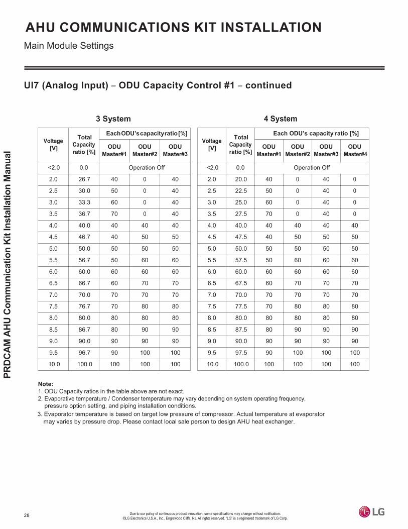
UI7 (Analog Input) – ODU Capacity Control #1 – continued
3 System 4 System
Note:1. ODU Capacity ratios in the table above are not exact.2. Evaporative temperature / Condenser temperature may vary depending on system operating frequency,
pressure option setting, and piping installation conditions.3. Evaporator temperature is based on target low pressure of compressor. Actual temperature at evaporator
may varies by pressure drop. Please contact local sale person to design AHU heat exchanger.
Voltage [V]
Total Capacity ratio [%]
Each ODU’s capacity ratio [%]
ODUMaster#1
ODUMaster#2
ODUMaster#3
ODUMaster#4
<2.0 0.0 Operation Off
2.0 20.0 40 0 40 0
2.5 22.5 50 0 40 0
3.0 25.0 60 0 40 0
3.5 27.5 70 0 40 0
4.0 40.0 40 40 40 40
4.5 47.5 40 50 50 50
5.0 50.0 50 50 50 50
5.5 57.5 50 60 60 60
6.0 60.0 60 60 60 60
6.5 67.5 60 70 70 70
7.0 70.0 70 70 70 70
7.5 77.5 70 80 80 80
8.0 80.0 80 80 80 80
8.5 87.5 80 90 90 90
9.0 90.0 90 90 90 90
9.5 97.5 90 100 100 100
10.0 100.0 100 100 100 100
Voltage [V]
Total Capacity ratio [%]
EachODU’scapacityratio[%]
ODUMaster#1
ODUMaster#2
ODUMaster#3
<2.0 0.0 Operation Off
2.0 26.7 40 0 40
2.5 30.0 50 0 40
3.0 33.3 60 0 40
3.5 36.7 70 0 40
4.0 40.0 40 40 40
4.5 46.7 40 50 50
5.0 50.0 50 50 50
5.5 56.7 50 60 60
6.0 60.0 60 60 60
6.5 66.7 60 70 70
7.0 70.0 70 70 70
7.5 76.7 70 80 80
8.0 80.0 80 80 80
8.5 86.7 80 90 90
9.0 90.0 90 90 90
9.5 96.7 90 100 100
10.0 100.0 100 100 100

29
Installation
Due to our policy of continuous product innovation, some specifications may change without notification. ©LG Electronics U.S.A., Inc., Englewood Cliffs, NJ. All rights reserved. “LG” is a registered trademark of LG Corp.
AHU COMMUNICATIONS KIT INSTALLATIONMain Module Settings
UI7 (Analog Input) – ODU Capacity Control #2
ODU Capacity Control #2 is available when DIP SW2-1 is On. Each Master ODU has the same operating ratio as shown in the table below.
Main Module
Note:1. ODU Capacity ratios mentioned in the table above are not exact.2. Evaporative temperature / Condenser temperature’ may vary depending on system operating frequency,
pressure option setting and piping installationconditions.
Voltage (V) ODU Capacity ratio (%)
Eva. Temp. (Te) Cond. Temp. (Tc) V Min. Max.
<1.0 - 0.7 Operation Off - -
1.0 0.8 1.2 100 39.2 122.0
2.0 1.8 2.2 90 41.0 120.2
3.0 2.8 3.2 80 43.7 116.6
4.0 3.8 4.2 70 46.4 111.2
5.0 4.8 5.2 60 50.0 104.0
6.0 5.8 6.2 50 55.4 96.8
7.0 6.8 7.2 45 57.2 91.4
8.0 7.8 8.2 40 59.0 86.0
9.0> 8.8 - Comp Off - -
°F °F
3. The evaporator temperature is based on target low pressure of compressor. The actual temperature atthe evaporator may vary by pressure drop. Please contact your LG representative to design an AHU heat exchanger.

30
PRDC
AM A
HU C
omm
unic
atio
n Ki
t Ins
talla
tion
Man
ual
Due to our policy of continuous product innovation, some specifications may change without notification. ©LG Electronics U.S.A., Inc., Englewood Cliffs, NJ. All rights reserved. “LG” is a registered trademark of LG Corp.
AHU COMMUNICATIONS KIT INSTALLATIONMain Module Settings
LED Display
An address for the main module is needed when PAHCMS000 is connected to an LG central controller
The address of main module can be set within ‘1~247’. In this case, the address of the main moduleshould be the same as the address in LG central controller.
Setting Method- Press ‘Set’ button (red)- Select ‘Addr’ in 7- Segment using ▲▼ buttons and then press the ‘Set’ button- Press ‘ESC’ button to exit
Communication ModuleMain Module
Name Port FunctionL01L LED1 Module Comm. TxL02L LED2 Module Comm. RxL03L LED3 ODU Comm. TxL04L LED4 ODU Comm. RxL05L LED5 Modbus Comm. TxL06L LED6 Modbus Comm. Rx
Main Module Address Setting

31
Installation
Due to our policy of continuous product innovation, some specifications may change without notification. ©LG Electronics U.S.A., Inc., Englewood Cliffs, NJ. All rights reserved. “LG” is a registered trademark of LG Corp.
AHU COMMUNICATIONS KIT INSTALLATIONCommunication Module
RS485 Communication Port
NTCThermistor
RemoteController
Electronic Expansion Valve
Note :Whenacommunicationmodule(orPAHCMR000) isconnectedtothemainmoduleofPAHCMS000,DOandUI incommunication module are not used.
Name Port Item Electrical Spec. Function
EEV 12 VDC/1/2/3/4 EEV Control Max32.8 ft EEV Control
Name Port Item Electrical Spec. Function
REMO +12V/SIG/GND Wire Remote Controller Max 164 ft Communication with Wired Remote Controller
Name Port Item Electrical Spec. FunctionThermistor Discharge NTC RI2/G Discharge air Thermistor NTC10kΩ,16.4 ft Discharge Air temperature sensor
ThermistorPipein NTC RI3/G Pipe in (Liquid) Thermistor NTC5kΩ,16.4 ft Inlet pipe (Liquid) Temp. sensor
Thermistor Pipe out NTC RI4/G Pipe out(Gas)Thermistor NTC5kΩ,16.4 ft Outlet pipe (Gas) Temp. sensor
Name Port Item Electrical Spec. Function
MULTI V IDUComm. RS485 CH2 MULTI V Comm.
(IDU A/B)
Max 3280 ft, 2C x 18~16 AWG
(shield wire)
Communication with MULTI V Outdoor unit
Single IDU Comm. SINGLE N/SIG Single split Comm.
(IDU A/B)
Max 246 ft, 2C x 18~16 AWG
(shield wire)
Communication with Single Split Outdoor unit

32
PRDC
AM A
HU C
omm
unic
atio
n Ki
t Ins
talla
tion
Man
ual
Due to our policy of continuous product innovation, some specifications may change without notification. ©LG Electronics U.S.A., Inc., Englewood Cliffs, NJ. All rights reserved. “LG” is a registered trademark of LG Corp.
AHU COMMUNICATIONS KIT INSTALLATIONDefrost Setting
It is a function to prevent outdoor units from simultaneously entering defrost when two or more outdoor units arelinked. The defrost operation function is only applied to the MULTI V outdoor unit (after MULTI V 5).
• Operating condition : Power on → Heating operation command• Stop condition : Power off or stop command• Function operation
1. This function is available when DIP switch is set to the Sequential Start Up.2. In order to prevent the outdoor unit from entering the defrosting at the same time of heating operation, only half of
the outdoor unit is in operation and the remaining outdoor units are operated after 10 minutes when the opera-tion command is received. (Sequential Start up is not operated in case of cooling operation)
Defrost Operation
Sequential Startup Control of Outdoor Unit
Example ODU Startup Control

33
Installation
Due to our policy of continuous product innovation, some specifications may change without notification. ©LG Electronics U.S.A., Inc., Englewood Cliffs, NJ. All rights reserved. “LG” is a registered trademark of LG Corp.
AHU COMMUNICATIONS KIT INSTALLATIONExternal Connection Diagrams
Multi V + EEV + DDC (Contact Signal)Available EEVKit models:-PRLK048A0/ PRLK096A0/ PRLK396A0
Outdoor unitEEV Kit - PRLK594A0 (requires EEV Controller PAEEVA020)INT(CEN) B
INT(CEN) A
R S T N
Liquid pipe
Gas pipePipe out (Gas)Thermistor
AirHandlingUnit(field supply) Pipe in (Liquid)Thermistor
DXCoil
Fuse
R S TNPower SupplyDischargeThermistor 1)
Central ControllerACP : CH5AC SMART : CH1
A+ B-
Power SupplyL NMain
moduleComm. module
ODU CapacityControl(0~10V)
A+ B-CH3
A+ B-CH2
RI2 G RI3 G RI4 GLocal AHUController
(Field Supplied)
CH 2 A+On/Off, Cool/Heat, Emer.stop CH 2 B-
AdapterOn/Off, Defrost, Alarm,
Comp. status12VL N
EEV SIG GND
Remote Controller
Refrigerant Piping (Field Supply)
Wire & Thermistor (LG Supply)
Wire (Field Supply)
AI/DI/DO Signal(Field Supply)
Note:1. The type of power supplyofoutdoorunit canvary depending on theoutdoormodel.2. Pleasemakewiringbetween LGcontrollerandoutdoorunitwith thesamepolarity.3. LG controller can be optionally applied with DDC.
Fan
cont
rol
IDU
B
IDU
A
Digital Output
Digital Input
Universal Input

34
PRDC
AM A
HU C
omm
unic
atio
n Ki
t Ins
talla
tion
Man
ual
Due to our policy of continuous product innovation, some specifications may change without notification. ©LG Electronics U.S.A., Inc., Englewood Cliffs, NJ. All rights reserved. “LG” is a registered trademark of LG Corp.
AHU COMMUNICATIONS KIT INSTALLATIONExternal Connection Diagrams
Single Zone + DDC (Contact Signal)PI 485
PMNFP14A1Single ZoneOutdoor unit
BUS -A
BUS -B
CN_PWR CN_CP(N)CN_CP(L)
CN_CENTRALCN_OUTLiquid pipe
Gas pipe
Pipe out (Gas) ThermistorAirHandlingUnit(field supply) Pipe in (Liquid) Thermistor
DXCoil
L NPower SupplyDischarge Thermistor
Central ControllerACP : CH5AC SMART : CH1
A+ B-
Main module
Comm. module
ODU CapacityControl(0~10V)
A+ B- A+ B-CH3 CH2
RI2 G RI3 G
SINGLE N
RI4 G
Local AHU Controller
(Field Supplied)
On/Off, Cool/Heat, Emer.stop SINGLE S
AdapterOn/Off, Defrost, Alarm,
Comp. status12VSIGGND
L N
RefrigerantPiping(FieldSupply)
Wire&Thermistor(LGSupply)
Wire (FieldSupply)
AI/DI/DO Signal(Field Supply)
Remote Controller
Note :1. The type of power supplyofoutdoorunit canvary depending on theoutdoormodel.2. Pleasemakewiringbetween LGcontrollerandoutdoorunitwith thesamepolarity.3. LG controller can be optionally applied with DDC.
Fan
cont
rol
1(L)
2(N
)
1(L)
2(N
)
3 (C
N_C
OM
)
EEVDigital Output
Digital Input
Universal Input

35
Installation
Due to our policy of continuous product innovation, some specifications may change without notification. ©LG Electronics U.S.A., Inc., Englewood Cliffs, NJ. All rights reserved. “LG” is a registered trademark of LG Corp.
AHU COMMUNICATIONS KIT INSTALLATIONExternal Connection Diagrams
Multi V + EEV + LG Control / DDC (Contact Signal)
Outdoor unitEEV Kit
INT(CEN) B
INT(CEN) A
R S T N
Liquid pipe
Gas pipePipe out (Gas) Thermistor
AirHandlingUnit(field supply) Pipe in (Liquid) Thermistor
DXCoil
Fuse
R S TNDischarge Thermisto r Power Supply 1)
Central ControllerACP : CH5AC SMART : CH1
A+ B-
Power SupplyL NMain
moduleComm. module
A+ B-CH3
A+ B-CH2
RI2 G RI3 G RI4 GModbus CommunicationLocal AHU
Controller(Field Supplied)
CH 2 A+A+ CH4 B- CH4
CH 2 B-
12VAdapter
L N EEV SIGGND
Remote Controller
RefrigerantPiping(FieldSupply)
Wire&Thermistor(LGSupply)
Wire (FieldSupply)
AI/DI/DO Signal(Field Supply)
Note :1. The type of power supplyofoutdoorunit canvary depending on theoutdoormodel.2. Pleasemakewiringbetween LGcontrollerandoutdoorunitwith thesamepolarity.3. LG controller can be optionally applied with DDC.
Fan
cont
rol
IDU
B
IDU
A
Available EEVKit models:-PRLK048A0/ PRLK096A0/ PRLK396A0- PRLK594A0 (requires EEV Controller PAEEVA020)

36
PRDC
AM A
HU C
omm
unic
atio
n Ki
t Ins
talla
tion
Man
ual
Due to our policy of continuous product innovation, some specifications may change without notification. ©LG Electronics U.S.A., Inc., Englewood Cliffs, NJ. All rights reserved. “LG” is a registered trademark of LG Corp.
AHU COMMUNICATIONS KIT INSTALLATIONExternal Connection Diagrams
Single Zone + LG Control / DDC (Contact Signal)PI 485
PMNFP14A1Single ZoneOutdoor unit
BUS -A
BUS -B
CN_CP(N)CN_CP(L)
CN_CENTRAL
CN_PWR
CN_OUTLiquid pipe
Gas pipe
Pipe out (Gas) ThermistorAirHandlingUnit(field supply) Pipe in (Liquid) Thermistor
DXCoil
L NPower SupplyDischarge Thermistor
Central Controller
ACP : CH5AC SMART : CH1
A+ B-
Main module
Comm. module
A+ B-CH3
A+ B-CH2
RI2 G RI3 G
SINGLE N SINGLE S
RI4 GModbus CommunicationLocal AHU
Controller(Field Supplied)
A+ CH4 B- CH4 Adapter
12VSIGGND
L N EEV
Remote Controller
RefrigerantPiping(FieldSupply)
Wire&Thermistor(LGSupply)
Wire (FieldSupply)
AI/DI/DO Signal(Field Supply)
Note :1. The type of power supplyofoutdoorunit canvary depending on theoutdoormodel.2. Pleasemakewiringbetween LGcontrollerandoutdoorunitwith thesamepolarity.3. LG controller can be optionally applied with DDC.
Fan
cont
rol
1(L)
2(N
)
1(L)
2(N
)
3 (C
N_C
OM
)

37
Installation
Due to our policy of continuous product innovation, some specifications may change without notification. ©LG Electronics U.S.A., Inc., Englewood Cliffs, NJ. All rights reserved. “LG” is a registered trademark of LG Corp.
AHU COMMUNICATIONS KIT INSTALLATIONDischarge Air Temperature Controller
Case 1: One AHU with One ODU / Standalone or DDC by Modbus
IDU communication lineDischarge ai r sensor
Pipe in & out sensor
ODU communication line
Module communication line Pipe in & out sensor
Pipe in & out sensor
Pipe in & out sensor
Communication moduleMaster02:00
RA temp.controller
Master02:01
RA temp. controller
Master02:02
RA temp.controllerMaster02:03
Outdoor Unit 00
Main Module
001
Modbus communication line
Power line
Remote Controller1)
L N
Discharge air temp. controller
Note:1. RemotecontrollershouldbeconnectedtoPAHCMS000.
2. LGCentral controlleraddressing fordischargeair temp.controller shouldbeset to thesameaddress as themainmodule’s address.
3. Address of Comm. module of PAHCMS000 (Central control address) must be set to ‘00’. The address for additional PAHCMR000 mustbeset withan order increasing by1. Also ODU address must be thesameas thepaired AHUcontroller.
4. All PAHCMR000 units need to be set as Master mode.
LGcentralized controller2)
orDDC
(Modbus)
Remote controller connected to PAHCMR000 can onlymonitor status.

38
PRDC
AM A
HU C
omm
unic
atio
n Ki
t Ins
talla
tion
Man
ual
Due to our policy of continuous product innovation, some specifications may change without notification. ©LG Electronics U.S.A., Inc., Englewood Cliffs, NJ. All rights reserved. “LG” is a registered trademark of LG Corp.
AHU COMMUNICATIONS KIT INSTALLATIONDischarge Air Temperature Controller
Case 2: One AHU with Multiple ODUs / Standalone or DDC by Modbus
Modbus communication line
IDU comm. line
Discharge air sensor
Pipe in & out sensor
Module communication line
Communication moduleMaster
02:003)
Outdoor Unit 00
Main Module
001 Remote Controller1)
IDU com Pipe in & out sensor
RA temp.controllerMaster02:01
Pipe in & out sensor
RA temp.controllerMaster02:02
ODU com Pipe in & out sensor
RA temp.controllerMaster02:03
Power line
Discharge air temp. controllerL NNote:1. RemotecontrollershouldbeconnectedtoPAHCMS000.2. LGCentral controlleraddressing fordischargeair temp.controller shouldbeset to thesameaddress as themainmodule’s address. 3. Address of Comm. module of PAHCMS000 (Central control address) must be set to ‘00’. The address for additional
PAHCMR000 mustbeset withan order increasing by1. Also ODU address must be thesameas thepaired AHUcontroller.4. All PAHCMR000 units need to be set as Master mode.
.line
Outdoor Unit 03
Outdoor Unit 02
m. line
Outdoor Unit 01
LG centralizedcontroller2)
orDDC (Modbus)
Remote controller connected to PAHCMR000 can only monitor status.

39
Installation
Due to our policy of continuous product innovation, some specifications may change without notification. ©LG Electronics U.S.A., Inc., Englewood Cliffs, NJ. All rights reserved. “LG” is a registered trademark of LG Corp.
AHU COMMUNICATIONS KIT INSTALLATIONDischarge Air Temperature Controller
Case 3: Multiple AHUs / Standalone or DDC by Modbus
Modbus communication line
IDU communication lineDischarge air sensor
Pipe in & out sensor
Pipe in & out sensor
Pipe in & out sensor
Pipe in & out sensor
Module communication line
RA temp.controller
Master02:03
Communication moduleMaster02:00
RA temp.controllerMaster02:01
RA temp.controllerMaster02:02
Outdoor Unit 00
Main module
001
Power line
Modbuscommunication
Remote Controller1)
lineDischarge air sensor
Pipe in & out sensor
L N
Pipe in & out sensor
Pipe in & out sensor
Pipe in & out sensor
Communication moduleMaster02:00
RA temp.controller
Master02:01
RA temp.controllerMaster02:02
RA temp.controllerMaster02:03
Outdoor Unit 00
Main module
002
ODU communication line
Remote Controller1)
L NDischarge air temp. controller
Note :1. RemotecontrollershouldbeconnectedtoPAHCMS000.2. LGCentral controlleraddressing fordischargeair temp.controller shouldbeset to thesameaddress as themainmodule’s address.3. Address of Comm. module of PAHCMS000 (Central control address) must be set to ‘00’. The address for additional
PAHCMR000 mustbeset withan order increasing by1. Also ODU address must be thesameas thepaired AHUcontroller.4. All PAHCMR000 units need to be set as Master mode.
LG centralized controller2)
or DDC
(Modbus)
Remote controller connected to PAHCMR000 can only monitor status.

40
PRDC
AM A
HU C
omm
unic
atio
n Ki
t Ins
talla
tion
Man
ual
Due to our policy of continuous product innovation, some specifications may change without notification. ©LG Electronics U.S.A., Inc., Englewood Cliffs, NJ. All rights reserved. “LG” is a registered trademark of LG Corp.
AHU COMMUNICATIONS KIT INSTALLATIONDischarge Air Temperature Controller
Case 4: One AHU / DDC by Contact Signal
IDU communication lineDischarge air sensor
Pipe in & out sensor
ODU communication line
Module communication line Pipe in & out sensor
Pipe in & out sensor
Pipe in & out sensor
Communication moduleMaster02:00
RA temp.controllerMaster02:01
RA temp.controllerMaster02:02
RA temp.controllerMaster02:03
Outdoor Unit 00
Main module
001
Modbus
Power lineContact signal
L N Remote Controller1)
Discharge air temp. controller
Note:1. RemotecontrollershouldbeconnectedtoPAHCMS000.
2. LGCentral controlleraddressing fordischargeair temp.controller shouldbeset to thesameaddress as themainmodule’s address.
3. Address of Comm. module of PAHCMS000 (Central control address) must be set to ‘00’. The address for additional PAHCMR000 mustbeset withan order increasing by1. Also ODU address must be thesameas thepaired AHUcontroller.
4. All PAHCMR000 units need to be set as Master mode.
DDC
LGcentralized
controller2)
Remote controller connected to PAHCMR000 can onlymonitor status.

41
Installation
Due to our policy of continuous product innovation, some specifications may change without notification. ©LG Electronics U.S.A., Inc., Englewood Cliffs, NJ. All rights reserved. “LG” is a registered trademark of LG Corp.
AHU COMMUNICATIONS KIT INSTALLATIONDischarge Air Temperature Controller
Case 5: One AHU with Multiple ODUs / DDC by Contact Signal
IDU communication lineDischarge air sensor
Pipe in & out sensor
ODU communication line
Module communication line Pipe in & out sensor
Pipe in & out sensor
Pipe in & out sensor
Communication moduleMaster02:00
RA temp.controllerMaster02:01
RA temp.controllerMaster02:02
RA temp.controllerMaster02:03
Outdoor Unit 00
Main module
001
Modbus
Power lineContact signal
L N Remote Controller1)
Discharge air temp. controller
Note:1. RemotecontrollershouldbeconnectedtoPAHCMS000.
2. LGCentral controlleraddressing fordischargeair temp.controller shouldbeset to thesameaddress as themainmodule’s address.
3. Address of Comm. module of PAHCMS000 (Central control address) must be set to ‘00’. The address for additional PAHCMR000 mustbeset withan order increasing by1. Also ODU address must be thesameas thepaired AHUcontroller.
4. All PAHCMR000 units need to be set as Master mode.
DDC
LGcentralized
controller2)
Remote controller connected to PAHCMR000 can onlymonitor status.

42
PRDC
AM A
HU C
omm
unic
atio
n Ki
t Ins
talla
tion
Man
ual
Due to our policy of continuous product innovation, some specifications may change without notification. ©LG Electronics U.S.A., Inc., Englewood Cliffs, NJ. All rights reserved. “LG” is a registered trademark of LG Corp.
AHU COMMUNICATIONS KIT INSTALLATIONDischarge Air Temperature Controller
Case 1: Multiple AHUs / DDC by Contact Signal
Contact Signal IDU communication lineDischarge air sensor
Pipe in & out sensor
Modbus communication line
Module communication line
Pipe in & out sensor
Pipe in & out sensor
Pipe in & out sensor
RA temp.controller<Master>
02:03
Communication module
<Master> 02:00
RA temp.controller<Master>
02:01
RA temp.controller<Master>
02:02
Main module
001
Outdoor Unit 00
Power line
Modbuscommunication Remote
Controller1)line Discharge air sensor
Pipe in & out sensor
L N
Pipe in & out sensor
Pipe in & out sensor
Pipe in & out sensor
RA temp.controller<Master>
02:03
Communication module
<Master> 02:00
RA temp.controller<Master>
02:01
RA temp.controller<Master>
02:02
Outdoor Unit 00
Main module
002
ODU communication line
Remote Controller1)
Discharge air temp. controllerL NNote:1. RemotecontrollershouldbeconnectedtoPAHCMS000. Remote controller connected to PAHCMR000 can only monitor status.2. LGCentral controlleraddressing fordischargeair temp.controller shouldbeset to thesameaddress as themainmodule’s address.3. Address of Comm. module of PAHCMS000 (Central control address) must be set to ‘00’. The address for additional
PAHCMR000 mustbeset withan order increasing by1. Also ODU address must be thesameas thepaired AHUcontroller.4. All PAHCMR000 units need to be set as Master mode.
LGcentralized controller2)
DDC

43
Installation
Due to our policy of continuous product innovation, some specifications may change without notification. ©LG Electronics U.S.A., Inc., Englewood Cliffs, NJ. All rights reserved. “LG” is a registered trademark of LG Corp.
Pipe In (Liquid)Thermistor
Pipe Out (Vapor)Thermistor
Air Handler Unit
Tie
Thermistor
45°
Step 1 Step 2
Thermistor Installation
AHU COMMUNICATIONS KIT INSTALLATION
ThermistorAir Flow
Air Handler Unit
AHU Communications Kit
Return AirThermistor
T
Figure 10: Location of the Return Air (Room) Thermistor (AHU Product Appearance May Vary).
Figure 11: Locations of the Pipe Thermistors.
Figure 12: Securing the Thermistor Cable.
Thermistor LocationsAll thermistors (one [1] return air [room] thermistor and two [2] pipe thermistor) must be correctly installed to ensure proper AHU Communications Kit operation.
1. Return Air (Room) Thermistor: Install it at the AHU heat exchanger inlet in the return air stream.
2. Pipe In Thermistor: Install it behind the distributor on the coldest area in the heat exchanger (contact the heat exchanger manufacturer for the precise location).
3. Pipe Out Thermistor: Install it at the outlet of the heat exchanger as close as possible to the heat exchanger.
System operation must be evaluated to determine if the AHU evaporator is protected against freezing up� Run a system test, and see if the AHU evaporator is freezing up�
Thermistor Cable Installation• Place the thermistor cables in a separate protective tube.
• Always add a pull-relief to the thermistor cable to avoid strain on the thermistor cable and loosening of the thermistor.
Strain on the thermistor cable or loosening of the thermistor may result in a bad contact and incorrect temperature measurements� Thermistors must be securely attached for proper operation�

44
PRDC
AM A
HU C
omm
unic
atio
n Ki
t Ins
talla
tion
Man
ual
Due to our policy of continuous product innovation, some specifications may change without notification. ©LG Electronics U.S.A., Inc., Englewood Cliffs, NJ. All rights reserved. “LG” is a registered trademark of LG Corp.
Wate
r
Thermistor Installation
AHU COMMUNICATIONS KIT INSTALLATION
Figure 13: Steps to Attaching the Pipe Thermistors.
45°Most SensitiveArea on the Thermistor
Maximize Contact Area
Figure 14: Thermistor Tip Contact Area.
Figure 15: Positioning the Thermistor Cable and Tip.
Tips for Attaching the Pipe In / Pipe Out Thermistors• Put the thermistor cable in a separate protective tube.• Always add a pull-relief to the thermistor cable to avoid strain on
the thermistor cable and loosening of the thermistor. Strain on the thermistor cable or loosening of the thermistor can result in bad contact with the pipe and incorrect temperature measurement.
Attaching the Pipe Thermistors
• To avoid water accumulating on the thermistor tip, position the thermistor cable slightly below the thermistor tip, or install the thermistor tip parallel with the cable.
Do not include a 90° angle or a kink in the thermistor cable, nor install the thermistor tip upside down.
1. Securely attach the thermistor to the pipe with a field-supplied pipe strap.
2. Insulate the thermistor with a field-supplied insulation sheet that is >5t.
Thermistors must be securely attached with a pipe strap� The equip-ment will not operate properly if thermistors are not making good physical contact in the appropriate installation location�
Step 1 Step 2

45
Installation
Due to our policy of continuous product innovation, some specifications may change without notification. ©LG Electronics U.S.A., Inc., Englewood Cliffs, NJ. All rights reserved. “LG” is a registered trademark of LG Corp.
SpecificationsTable 13: EEV Kit Specifications Table.
EEV Kit Design Parameters• Maximum of one (1) EEV Kit can be connected to one (1) AHU
Communications Kit.• Minimum coil entering air temperature for heating mode is 41°F.• Requires field-supplied six-conductor communication cable to
connect to AHU Communications Kit.
• Maximum distance between EEV Kit and AHU Communications Kit is thirty-two (32) feet.
• Designed for indoor installations (field-supplied waterproof enclo-sure must be used when installing outdoors).
Figure 16: EEV Kit.
EEV KIT INSTALLATIONIntroduction, Specifications, and Design Parameters
IntroductionWhen used with the LG AHU Communications Kit (sold separately), the LG EEV Kit controls refrigerant flow between LG Multi V air-source or water-source units and a third-party air handler unit (AHU).The EEV Kits for PAHCMS000 are offered in four sizes: • PRLK048A0 supports 12 through 96 MBH (8 tons maximum)• PRLK096A0 supports 96.1 through 192 MBH (16 tons maximum)• PRLK396A0 supports 192.1 MBH through 396 MBH (32 ton maximum)• PRLK594A0 supports 396.1 MBH through 594 MBH coils (48 ton maximum, requires EEV Controller
Module PAEEVA020).
Model Number PRLK048A0 PRLK096A0 PRLK396A0 PRLK594A0
For Use With PAHCMR000 and PAHCMS000
PAHCMS000 with EEV Controller Module PAEEVA020
Power Supply Requirements Powered by Air Handler Unit Communica�ons Kit (12 VDC) Ambient Opera�ng Temperature Range -4 to 149F
Ambient Opera�ng Humidity Range 0 to 98% (Non-condensing)
Dimensions (in., W x H x D) 8-5/8 x 15-15/16 x 3-5/16 13-25/32 x 7-3/32 x 13-39/64
16-1/8 x 7-3/32 x 13-39/64
Net Weight (lbs.) 6.8 11.0 15.4 Shipping Weight (lbs.) 7.9 12.1 16.5
Maximum Air Handler Unit Capacity (Btu/h) 96,000 192,000 396,000 594,000
Communica�ons Cable AWG 18 x 6 Stranded, Shielded Copper Wire Refrigerant Type R410A
Table 14: EEV Kit Compatibility Table.
PAHCMR000 PAHCMS000PRLK048A0
(8 tons max) HP/HR HP
PRLK096A0 (16 tons max) HP HP
PRLK396A0 (32 tons max) HP HP
PRLK594A0 (48 tons max) NA
HP (requires EEV module)
AHU Communica�on KitEEV Kit
HP = Heat Pump; HR = Heat Recovery

46
PRDC
AM A
HU C
omm
unic
atio
n Ki
t Ins
talla
tion
Man
ual
Due to our policy of continuous product innovation, some specifications may change without notification. ©LG Electronics U.S.A., Inc., Englewood Cliffs, NJ. All rights reserved. “LG” is a registered trademark of LG Corp.
EEV KIT INSTALLATIONEEV Kit Parts
1
25
3
4 4
8
7
6
Diagram Label Part Name Quantity
1 Top Panel One (1)2 Bracket Two (2)3 Terminal Box One (1)4 Cable Connectors Two (2)5 Pipe Insulation One (1)
6 Electronic Expansion Valve Assembly(EEV, Strainer, Tube) One (1)
7 Support Tie One (1)8 Bottom Panel One (1)
Table 15: PRLK048A0 and PRLK096A0 EEV Parts Table.Figure 17: PRLK048A0 and PRLK096A0 EEV Parts.
1
2
3
4
Table 16: PRLK396A0 EEV Parts Table.Diagram
Label Part Name Quantity
1 Panel A, Upper One (1)2 Panel B, Upper One (1)3 Bracket Two (2)4 Panel, Base One (1)
Figure 18: PRLK396A0 EEV Parts.

47
Installation
Due to our policy of continuous product innovation, some specifications may change without notification. ©LG Electronics U.S.A., Inc., Englewood Cliffs, NJ. All rights reserved. “LG” is a registered trademark of LG Corp.
EEV KIT INSTALLATIONEEV Kit Parts
Table 17: PRLK594A0 EEV Parts Table.
Figure 19: PRLK594A0 EEV Parts.
Diagram Label Part Name Quantity
1 Panel A, Upper One (1)2 Panel B, Upper One (1)3 Bracket Two (2)4 Panel, Base One (1)
1
2
3
4

48
PRDC
AM A
HU C
omm
unic
atio
n Ki
t Ins
talla
tion
Man
ual
Due to our policy of continuous product innovation, some specifications may change without notification. ©LG Electronics U.S.A., Inc., Englewood Cliffs, NJ. All rights reserved. “LG” is a registered trademark of LG Corp.
EEV KIT INSTALLATION
7-1/2 inches
Ø1/4”
13-5/
16 in
ches
Mounting the PRLK048A0/PRLK096A0 EEV Kit1. Remove the Top Panel by unscrewing the screws
at the four (4) corners.2. Using the Bottom Panel as a template, mark the
location on the wall or ceiling where the holes for the screws should be placed. Drill the four (4) holes.
3. Attach the EEV Bottom Panel securely using four (4) field-supplied 1/4 inch long screws.
Figure 20: Removing the Screws. Figure 21: EEV Bottom Panel Hole Dimensions.
Mounting the EEV Kit
Mounting the PRLK396A0 / PRLK594A0 EEV Kit
1. Remove the two screws from the EEV kit base plate
3. Remove the four screws from the cover plate
4. Remove the cover plate 5. Drill holes in the correct locations and use 4 field-provided screws to secure the EEV kit.
Model length (inch)A B
PRLK396A0 10-3/4 7-1/2
2. Remove the base plate.
A
Pipe diameter 5/8”
B
Holesize1/4”
Pipe diameter 5/8”
PRLK594A0 10-3/4 7-1/2

49
Installation
Due to our policy of continuous product innovation, some specifications may change without notification. ©LG Electronics U.S.A., Inc., Englewood Cliffs, NJ. All rights reserved. “LG” is a registered trademark of LG Corp.
EEV KIT INSTALLATIONPreparing the Pipes
A. Inlet Pipes from the Air Source / Water-Source Unit. B. Outlet pipes to AHU Evaporator Coil. C. Pipe Support Bracket. D. Pipe Insulation. E. EEV Assembly. F. 1/2 Inch O.D. Field Piping (Inlet / Outlet).
E
D
C (Two[2])
F
F
B A
Preparing the PipesPRLK048A0 and PRLK096A01. Unscrew the four (4) M4 screws and detach the two (2) EEV As-
sembly pipe support brackets.2. Remove the EEV Assembly; remove the pipe insulation from the
EEV Assembly.3. If cutting pipe, refer to the cutting instructions on the next page.4. Braze the field-supplied inlet / outlet piping to the EEV Assembly.
See next page for brazing instructions.
Figure 22: PRLK048A0 and PRLK096A0 EEV Kits.
PRLK396A0 / PRLK594A01 Check the inlet/outlet pipe before brazing the EEV KIT.
AHU side Outdoorunit side
A
Air-conditioning standard refrigerant flow
3 Braze the connector pipe (not provided) at the outdoor unit. 4 When connecting the outdoor unit's connector pipe and the EEV KIT pipe, be sure to use a
socket (not provided) that meets the necessary specifications. 5 As the size of the EEV KIT pipe and the outdoor unit's connector pipe could vary, check the
sizes beforehand and use a socket that meets the necessary specifications. 6 When brazing, make sure to follow safety precautions at all times. 7 Be sure to insulate pipe A after welding with insulation (15T or more).
Notes:Be sure to pass nitrogen through when brazing. Failure to do so could cause the compressorto not function properly or become damaged. It is essential that the pipe is wrapped with a wet towel before and after brazing. Failureto do so could result in equipment damage.Use a protective panel or be especially cautious not to let welding sparks come in contactwith the AHU panel.After brazing, be sure to test for leakage.Failure to properly insulate the pipe after welding may result in leakage.
Outdoor unit connector pipe(not included)
Connector socket(not included)
(not included)
AHU and OutdoorUnit Connection
AHU Connection
2 If cutting pipe, refer to the cutting instructions on the next page.
Outlet Inlet
Connectorsocket (elbow)(not included)

50
PRDC
AM A
HU C
omm
unic
atio
n Ki
t Ins
talla
tion
Man
ual
Due to our policy of continuous product innovation, some specifications may change without notification. ©LG Electronics U.S.A., Inc., Englewood Cliffs, NJ. All rights reserved. “LG” is a registered trademark of LG Corp.
EEV KIT INSTALLATION
Liner
Fold
A B CD
f
Brazing
E
F
A Refrigerant PipingB Area to be BrazedC Tape
D Hands-On ValveE Pressure-Reducing ValveF Nitrogen
Insulating the Piping1. After brazing is complete, place the Pipe Insulation back on the
EEV Assembly. Peel off the liner, fold the insulation as shown in the figure at right, and press down to seal.
2. Fully insulate the field piping up to the EEV Assembly. To avoid condensation, make sure there are no gaps between the field piping insulation and the EEV Assembly insulation. Finish the connection with tape.
3. To secure the EEV Assembly, re-install the two (2) pipe support brackets using the four (4) M4 screws.
Brazing • Use a nitrogen purge set to 0.02 MPa while brazing.
Brazing without a nitrogen purge will create a large amount of oxidization on the inside of the pipes, adversely affecting valves and compressors in the refrigerating system and preventing normal system operation�• When brazing the field piping to the EEV Kit Assembly, use a wet cloth to pro-
tect and ensure that the main EEV body temperature does not exceed 248°F.• Make sure that the other parts such as electrical box, support ties, and wiring
are also protected from direct flames during brazing.• After brazing is complete, use medical grade dry nitrogen and pressure
test the refrigerant piping system to a minimum of 550 psi for a period of 24 hours. Pressurize the liquid, low pressure vapor, and high pressure vapor pipes (heat recovery systems only) of the air-source / water-source units concurrently. The test must be done with the air-source / water-source unit service valves closed. (For more details, refer to the manual of the respective air-source / water-source installation manuals.)
Figure 23: Brazing Field Piping to EEV Assembly.
Brazing and Insulating the Piping
Figure 24: Installing the Insulation.
Cutting Pipe
1 Use a copper pipe cutter to cut the pipe in a straight line.
2 When cutting, tilt the pipe end downward to prevent burrs from getting inside the pipe. After cutting, use a reamer to remove any burrs from inside the pipe.
Copper pipe cutter 90° Incline Roughness
Pipe
Copper pipe cutter 90° Incline Roughness
Pipe
Notes:The presence of burrs can result in refrigerant leakage.Remove any burrs with a reamer.Cutting dust could lead to malfunctioning if it gets inside the pipe.
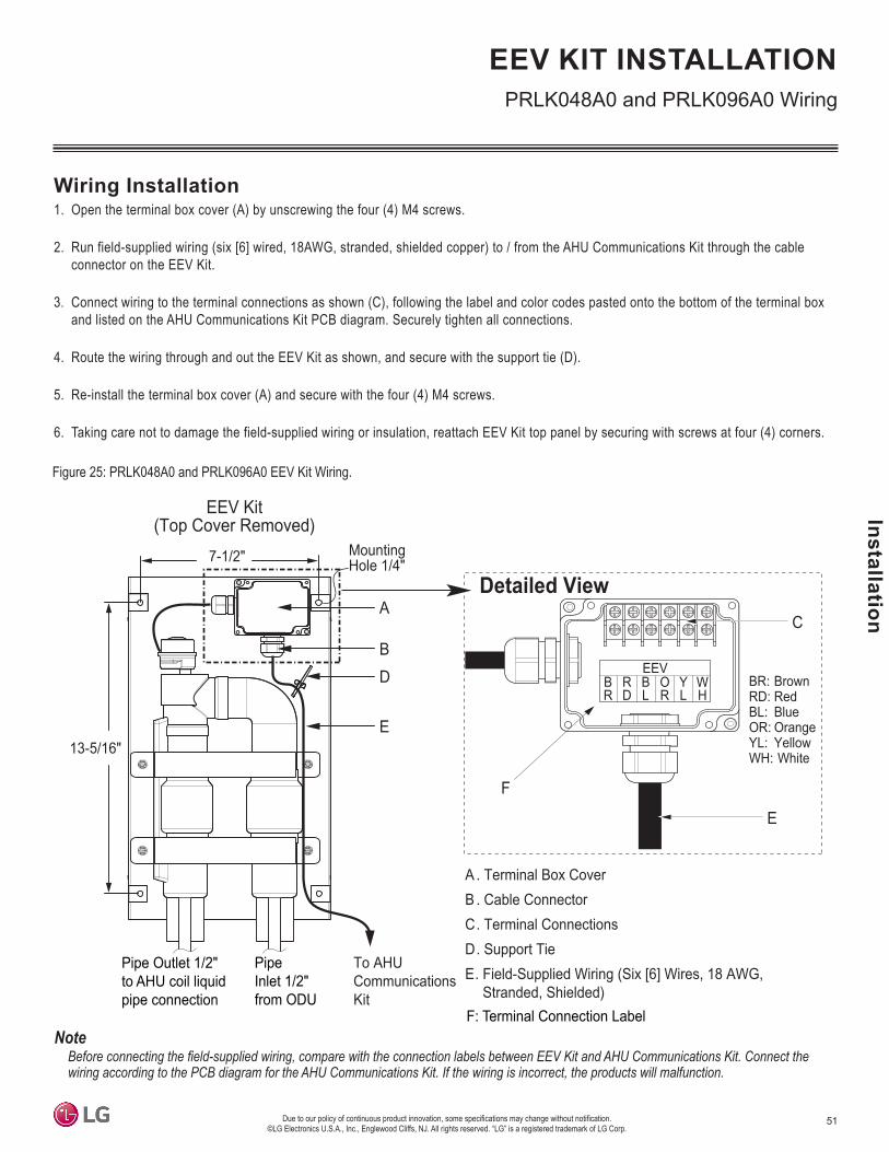
51
Installation
Due to our policy of continuous product innovation, some specifications may change without notification. ©LG Electronics U.S.A., Inc., Englewood Cliffs, NJ. All rights reserved. “LG” is a registered trademark of LG Corp.
EEV KIT INSTALLATION
A . Terminal Box CoverB . Cable ConnectorC. Terminal ConnectionsD. Support TieE. Field-Supplied Wiring (Six [6] Wires, 18 AWG,
Stranded, Shielded)
A
BD
E
BR
RD
BL
OR
YL
WH
EEV
C
Detailed View
E
BR: BrownRD: RedBL: BlueOR: OrangeYL: YellowWH: White13-5/16"
7-1/2" MountingHole 1/4"
To AHUCommunicationsKit
EEV Kit(Top Cover Removed)
Pipe Outlet 1/2"to AHU coil liquidpipe connection
PipeInlet 1/2"from ODU
F: Terminal Connection Label
F
Figure 25: PRLK048A0 and PRLK096A0 EEV Kit Wiring.
Wiring Installation1. Open the terminal box cover (A) by unscrewing the four (4) M4 screws.
2. Run field-supplied wiring (six [6] wired, 18AWG, stranded, shielded copper) to / from the AHU Communications Kit through the cable connector on the EEV Kit.
3. Connect wiring to the terminal connections as shown (C), following the label and color codes pasted onto the bottom of the terminal box and listed on the AHU Communications Kit PCB diagram. Securely tighten all connections.
4. Route the wiring through and out the EEV Kit as shown, and secure with the support tie (D).
5. Re-install the terminal box cover (A) and secure with the four (4) M4 screws.
6. Taking care not to damage the field-supplied wiring or insulation, reattach EEV Kit top panel by securing with screws at four (4) corners.
Before connecting the field-supplied wiring, compare with the connection labels between EEV Kit and AHU Communications Kit. Connect the wiring according to the PCB diagram for the AHU Communications Kit� If the wiring is incorrect, the products will malfunction�
PRLK048A0 and PRLK096A0 Wiring

52
PRDC
AM A
HU C
omm
unic
atio
n Ki
t Ins
talla
tion
Man
ual
Due to our policy of continuous product innovation, some specifications may change without notification. ©LG Electronics U.S.A., Inc., Englewood Cliffs, NJ. All rights reserved. “LG” is a registered trademark of LG Corp.
EEV KIT INSTALLATION PRLK396A0 Wiring
Figure 26: PRLK396A0 EEV Kit Wiring.
Wiring Installation1. Open the terminal box cover.2. For PRLK396A0 / PRLK594A0, run the field-supplied wiring (six [6] wired, 18AWG, stranded, shielded copper) to / from the AHU Commu-
nications Kit through the cable connector on the EEV Kit.3. Connect wiring to the terminal connections following the label and color codes pasted onto the bottom of the terminal box and shown
below. Securely tighten all connections.4. Route the wiring through and out the EEV Kit as shown, and secure with the support tie (D).5. Re-install the terminal box cover and secure the cover with the four (4) screws.6. Taking care not to damage the field-supplied wiring or insulation, reattach the EEV Kit Top Panel by securing it with the screws at the four
(4) corners.
BR : BrownRD : RedBL : Blue
OR : OrangeYL : YellowWH : White
Field Wiring
A
B
PRLK396A0 EEV Kit(cover removed)
10-3/
4
7-1/2
MountingHole 1/4
Pipe Outlet 5/8to AHU coil liquidpipe connection
Pipe Inlet 5/8from ODU
DD
AHU controller
Detail
A. Terminal Box CoverB. Cable Strain Relief ConnectorC. Terminal ConnectorD. Electrical Wiring (field supplied, 6 wires, 18 AWG, stranded, shielded
Figure 27: PRLK594A0 EEV Kit Wiring.
A
B
PRLK594A0 EEV Kit(cover removed)
AHU controller
AHU EEV controller(sold separately)
D
Detail
B RR D
B LO R
Y LW H
EEV
BR: BrownRD: RedBL: BlueOR: OrangeYL: YellowWH: White
C
9-7/8
MountingHole 1/4”
Pipe Outlet 5/8to AHU coil liquidpipe connection
Pipe Inlet 5/8from ODU
A. Terminal Box CoverB. Cable Strain Relief ConnectorC. Terminal ConnectorD. Electrical Wiring (field supplied, 6 wires, 18 AWG, stranded, shielded
10-3/
4
D
scale : inch
D
BR : BrownRD : RedBL : Blue
OR : OrangeYL : YellowWH : White
Field Wiring

53
Installation
Due to our policy of continuous product innovation, some specifications may change without notification. ©LG Electronics U.S.A., Inc., Englewood Cliffs, NJ. All rights reserved. “LG” is a registered trademark of LG Corp.
EEV KIT INSTALLATIONControl Functions
Individual Controller
Note: 1. Pipe temperature display is unavailable on the Simple remote controller.2. Control function is unavailable when Contact Signal control is used (DIP SW1-1 is Off).3. A wired remote controller is also required if using a wireless remote controller.4. Partial lock is available only with Premium remote controller.5. Refer to the product manual of the remote controller.
Function List PAHCMS000
Basic Function
Operating On / Off OOperation Mode Control Cooling / Heating onlyDesired Return Air Temperature Setting XReturn Air Temperature Display XDesired Discharge Air Temperature Setting 60 ~ 80 °FDischarge Air Temperature Display 51.8 ~ 103.1 °FFan Speed Control XAuto Swing -Vane Control (Louver Angle) -Child Lock / All button Lock X
Advanced Function
Schedule OPartial Lock XDual Set point XPipe Temperature display O 1
Error Code Display ODefrost Status Defrost / NormalCompressor Status On / OffFilter Sign -Error History X
ETCUnit of Temperature control 1.0 °FElectric Failure compensation O

54
PRDC
AM A
HU C
omm
unic
atio
n Ki
t Ins
talla
tion
Man
ual
Due to our policy of continuous product innovation, some specifications may change without notification. ©LG Electronics U.S.A., Inc., Englewood Cliffs, NJ. All rights reserved. “LG” is a registered trademark of LG Corp.
EEV KIT INSTALLATIONControl Functions
LG Central ControllerFunction List PAHCMS000
Basic Function
Operating On/Off OOperating Mode Control Cooling / Heating onlyDesired Return Air Temperature Setting XReturn Air Temperature Display XDesired Discharge Air Temperature Setting 60 ~ 80 °F Discharge Air Temperature Display -58.0~ 212.0 °FFan Speed Control XAuto Swing -All Lock X
Additional function
Schedule OPartial Lock XAuto Change Over XSet Back X2 Set Auto Mode XPipe Temperature XError Code Display ODefrost Status XOutdoor unit Cycle Monitoring XFilter Sign -Emergency Stop OEnergy Navigation X
Auto ControlPeak Control
Priority control XODU capacity control X
Time limit control XDevice Interlocking X
Energy ReportPower Consumption XRun time XSending Email / Save to PC or USB X
HistoryReport Error / ControlSending Email / Save to PC or USB O
ETCUnit of Temperature control 1.0 °FRemote Access O
1. Control function is unavailable when Contact Signal control is used (DIP SW1-1 is Off).2. PI485GW is required for Single Zone application.
Note:

55
Installation
Due to our policy of continuous product innovation, some specifications may change without notification. ©LG Electronics U.S.A., Inc., Englewood Cliffs, NJ. All rights reserved. “LG” is a registered trademark of LG Corp.
EEV KIT INSTALLATIONControl Functions
Memory MapFunction Code
Memory MapFunction CodeRegister Description Value explanation
1 2 3 4 5 600001 Operating On / Off ● - - - ● - 0: Off / 1: On00002 Reserved - - - - - - -00003 Reserved - - - - - - -00004 Reserved - - - - - - -00005 Reserved - - - - - - -00006 Reserved - - - - - - -00007 Reserved - - - - - - -00008 Reserved - - - - - - -10001 Error Status - ● - - - - 0: Normal / 1: Error10002 Operation Status - ● - - - - 0: Off / 1: On10003 Defrost Status - ● - - - - 0: Normal / 1: Defrost10004 Reserved - - - - - - -10005 Reserved - - - - - - -10006 Reserved - - - - - - -10007 Reserved - - - - - - -10008 Reserved - - - - - - -10009 Reserved - - - - - - -10010 Reserved - - - - - - -10011 ODU#1 Operation Status - ● - - - - 0: Off / 1: On10012 ODU#1 Comp. Status - ● - - - - 0: Off / 1: On10013 ODU#1 Defrost Status - ● - - - - 0: Normal / 1: Defrost10014 ODU#1 Error Status - ● - - - - 0: Normal / 1: Error10015 ODU#2 Operation Status - ● - - - - 0: Off / 1: On10016 ODU#2 Comp. Status - ● - - - - 0: Off / 1: On10017 ODU#2 Defrost Status - ● - - - - 0: Normal / 1: Defrost10018 ODU#2 Error Status - ● - - - - 0: Normal / 1: Error10019 ODU#3 Operation Status - ● - - - - 0: Off / 1: On10020 ODU#3 Comp. Status - ● - - - - 0: Off / 1: On10021 ODU#3 Defrost Status - ● - - - - 0: Normal / 1: Defrost10022 ODU#3 Error Status - ● - - - - 0: Normal / 1: Error10023 ODU#4 Operation Status - ● - - - - 0: Off / 1: On10024 ODU#4 Comp. Status - ● - - - - 0: Off / 1: On10025 ODU#4 Defrost Status - ● - - - - 0: Normal / 1: Defrost10026 ODU#4 Error Status - ● - - - - 0: Normal / 1: Error
Code Description Register0x01 Read Coils 00001~000080x02 Read Discrete inputs 10001~100300x03 Read Holding Registers 40001~400100x04 Read Input Registers 30001~300160x05 Write Single Coil 00001~000080x06 Write Single Holding Register 40001~40010

56
PRDC
AM A
HU C
omm
unic
atio
n Ki
t Ins
talla
tion
Man
ual
Due to our policy of continuous product innovation, some specifications may change without notification. ©LG Electronics U.S.A., Inc., Englewood Cliffs, NJ. All rights reserved. “LG” is a registered trademark of LG Corp.
EEV KIT INSTALLATIONControl Functions
Memory Map - continued
Function Code
Note :1. For capacity ratio, refer to the capacity setting table of UI7 (0 - 10V).2. Error Code: 1 x xxx
Error Code Module Number
Register Description Value explanation1 2 3 4 5 6
10027 Reserved - - - - - - -10028 Reserved - - - - - - -10029 Reserved - - - - - - -10030 Reserved - - - - - - -30001 Error Code - - - ● - - 1xxxx 2)
30002 Reserved - - - - - - -30003 Reserved - - - - - - -30004 Reserved - - - - - - -30005 Reserved - - - - - - -30006 Reserved - - - - - - -30007 Reserved - - - - - - -30008 Reserved - - - - - - -30009 Reserved - - - - - - -30010 Reserved - - - - - - -30011 RA Temp. - - - ● - - (x10)30012 Reserved - - - - - - -30013 SA Temp. - - - ● - - (x10) 30014 Reserved - - - - - - -30015 Reserved - - - - - - -30016 Reserved - - - - - - -40001 Operation Mode - - ● - - ● 0:Cooling /2:Fan /4:Heating40002 Capacity 1) - - ● - - ● 0, 2.0V~10V (x10, 0.5V)40003 Cooling Target Temp. - - ● - - ● (x10, 1.0 40004 Heating Target Temp. - - ● - - ● (x10, 1.0 °C) 40005 Reserved - - - - - - -40006 Reserved - - - - - - -40007 Reserved - - - - - - -40008 Reserved - - - - - - -40009 Reserved - - - - - - -40010 Reserved - - - - - - -
15.6 ~ 30°C
-50 ~ 100°C
-50 ~ 100°C
°C)15.6 ~ 30°C

57
Installation
Due to our policy of continuous product innovation, some specifications may change without notification. ©LG Electronics U.S.A., Inc., Englewood Cliffs, NJ. All rights reserved. “LG” is a registered trademark of LG Corp.
TestingBefore testing, make sure all information is understood completely, and follow the guidelines listed in this manual.• Check the air-source / water-source unit refrigerant piping, additional refrigerant charge, maximum allowable piping length, and opening the
shut-off valve. (For more detailed information, see the respective air-source / water-source unit installation manual).• Operate the testing procedure.1. Connect the power, and turn the system on.2. Check remote controller for error codes.
• For more detailed function of the wired remote controller, refer to its Owner’s / Installation Manual.• Buttons 3, 4, 11, 12 on the wired remote controller do not operate�
TESTING
Figure 28: Wired Remote Controller Buttons.
1
789
10
11
1312
14151617
23
4
56
1. Operation indication screen2. Set temperature button3. Fan Speed button4. Set back button5. Operation mode selection button6. Wireless receiver - some equipment are not
equipped to receive the wireless signals7. Sub-function button8. Ventilation button9. Reservation button10. Air flow button11. Cooling desired temperature12. Function setting button13. Up, Down, Left, Right button14. On/Off button15. Heating desired temperature16. Setting/Cancel button17. Exit button

58
PRDC
AM A
HU C
omm
unic
atio
n Ki
t Ins
talla
tion
Man
ual
Due to our policy of continuous product innovation, some specifications may change without notification. ©LG Electronics U.S.A., Inc., Englewood Cliffs, NJ. All rights reserved. “LG” is a registered trademark of LG Corp.
TROUBLESHOOTING
Error Code Description Details
CH01 Return Air (Room) Thermistor Error Return air (room) thermistor has disconnected from AHU, orhas short circuited.
CH02 Pipe In Thermistor Error Pipe in thermistor has disconnected from AHU, or has shortcircuited.
CH03 Communication Error Between Wired Remote Controller and AHU Communications Kit
No communication signal for more than three (3) minutesfrom the controller to the AHU Communications Kit.
CH05 Communication Error BetweenAHU Communications Kit and Air-Source / Water-Source Unit
No communication signal for more than five (5) consecutiveminutes from AHU Communications Kit to the Air-SourceHeat Pump Unit.
CH06 Pipe Out Thermistor Error Pipe out thermistor has disconnected from AHU, or has shortcircuited.
Problem Cause Solution
AHU CommunicationsKit Does Not Work
No Power Check the power supply electrical connections and voltage.Wiring is Incorrect Check the AHU Communications Kit electrical connections (see wiring diagram).
AHU Communications Kitis Damaged Check AHU Communications Kit electrical and mechanical components.
EEV Kit Does Not Work
Wiring is Incorrect Check the EEV Kit electrical connections.Piping is Incorrect Check the piping connections between the EEV Kit and the outdoor unit.
Table 18: Troubleshooting.
Table 19: Error Code Table.
Error Codes• The error code function indicates when an operation failure occurs in the system, and provides self-diagnosis about the type of error.
• The error code is displayed on the wired remote controller and the control board LED on the air-source heat pump unit.
• If two or more two errors occur simultaneously, the smallest of the error code numbers is displayed first.
• When the problem causing the error code to appear is fixed, then the error code will immediately stop displaying on the LED.
Troubleshooting

Contact your LG representative if you have any questions about the AHU Communications Kit or its installation.

LG Electronics, U.S.A., Inc.Commercial Air Conditioning Division4300 North Point ParkwayAlpharetta, Georgia 30022www.lg-vrf.com IM_AHU_Comm_Kit_PAHCMS000_8_18
LG Customer Information Center, Commercial Products1-888-865-3026 USA
Follow the prompts for commercial A/C products.