tm ahu 60r410a onoff t sa na 171205 air handler unit r410a
TRANSCRIPT

TM_AHU_60R410A_ONOFF_T_SA_NA_171205
AIR HANDLER UNIT R410A 60HZ ON-OFF CONTROL 2017 TECHNICAL MANUAL

Table of Contents Page
1. Specifications ................................................................................................ 4
1. Model Reference
2. General Specifications
3. Dimensional Drawings
4. Electrical Wiring Diagrams
5 Refrigerant Cycle Diagrams
6. Capacity Tables
7. Capacity Correction Factor for Height Difference
8. Noise Criterion Curves
9. Electrical Characteristics
10. Static Pressure
2. Product Features ........................................................................................... 30
1. Operation Modes and Functions
3. Installation .................................................................................................... 32
1. Installation Overview
2. Location Selection
3. Indoor Unit Installation
4. Outdoor Unit Installation
5. Refrigerant Pipe Installation
6. Drainage Pipe Installation
7. Vacuum Drying and Leakage checking
8. Additional Refrigerant Charge
9. Engineering of Insulation
10. Engineering of Electrical Wiring
11. Test Operation

Table of Contents Page
4. Static Pressure Design .................................................................................. 46
1. Introduction
2. Charts for friction losses in round ducts
3. Dynamic losses
4. Corresponding relation between Rectangular duct and Round duct
5. Method for duct calculation
6. Unit conversion
7. Recommended outlet velocity for different occasions
4. Troubleshooting ............................................................................................ 51
1. General Troubleshooting
2. Error Diagnosis and Troubleshooting Without Error Code
3. Quick Maintenance by Error Code
4. Troubleshooting
Appendix ............................................................................................................. 65
i) Temperature Sensor Resistance Value Table for T1,T2,T3 and T4 (°C – K)
ii) Pressure On Service Port

Contents
1. Model Reference ....................................................................................................2
2. General Specifications ...........................................................................................3
3. Dimensional Drawings ..........................................................................................7
4. Electrical Wiring Diagrams ..................................................................................11
5 Refrigerant Cycle Diagrams ................................................................................20
6. Capacity Tables ....................................................................................................23
7. Capacity Correction Factor for Height Difference .............................................63
8. Noise Criterion Curves .........................................................................................72
9. Electrical Characteristics ......................................................................................78
10. Static Pressure ......................................................................................................78
Specifications
Spec
ifica
tio
ns
Page 5
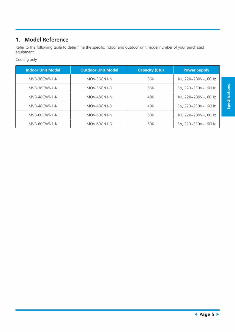
1. Model ReferenceRefer to the following table to determine the specific indoor and outdoor unit model number of your purchased equipment.
Cooling only
Indoor Unit Model Outdoor Unit Model Capacity (Btu) Power Supply
MVB-36CWN1-N MOV-36CN1-N 36K 1Φ, 220~230V~, 60Hz
MVB-36CWN1-N MOV-36CN1-D 36K 3ɸ, 220~230V~, 60Hz
MVB-48CWN1-N MOV-48CN1-N 48K 1Φ, 220~230V~, 60Hz
MVB-48CWN1-N MOV-48CN1-D 48K 3ɸ, 220~230V~, 60Hz
MVB-60CWN1-N MOV-60CN1-N 60K 1Φ, 220~230V~, 60Hz
MVB-60CWN1-N MOV-60CN1-D 60K 3ɸ, 220~230V~, 60Hz

Specifi
cation
s
Page 6
2. General SpecificationsIndoor model MVB-36CWN1-N MVB-36CWN1-N MVB-48CWN1-N
Outdoor model MOV-36CN1-N MOV-36CN1-D MOV-48CN1-N
Indoor Power supply V-Ph-Hz 220-230V,1Ph,60Hz 220-230V,1Ph,60Hz 220-230V,1Ph,60Hz
Outdoor Power Supply V-Ph-Hz 220-230V,1Ph,60Hz 220-230V,3Ph,60Hz 220-230V,1Ph,60Hz
Max. input consumption W 5400 5000 6500
Max. current A 25.5 15.0 30.7
Indoor fan motor
Model YKS-230-6-18 YKS-230-6-18 YKS-250-6-30
Old Model YDK230-6X YDK230-6X YDK250-6X-2
Qty January-00 January-00 January-00
Input W 420.0 420.0 515/-/450
Capacitor uF 15 15 12UF/450V
Speed(Hi/Mi/Lo) r/min 1100/980 1100/980 830/-/765
Indoor coil
a.Number of rows 3.0 3.0 4.0
b.Tube pitch(a)x row pitch(b) mm 21*13.37 21*13.37 21*13.37
c.Fin spacing mm 1.3 1.3 1.3
d.Fin type (code) Hydrophilic aluminium Hydrophilic aluminium Hydrophilic aluminium
e.Tube outside dia.and type mm Φ7,innergroove tube Φ7,innergroove tube Φ7,innergroove tube
f.Coil length x height x width mm 415X336X40.11 415X336X40.11 444X378X53.48
g.Number of circuits 6 6 8
Indoor air flow (Hi/Mi/Lo) m3/h 1648/-/1465 1648/-/1465 1932/-/1816
Sound level (sound pressure) dB(A) 51.9 51.9 54
Throttle type Throttle valve Throttle valve Throttle valve
Indoor unit
Dimension(W*D*H) mm 520x460x774 520x460x774 500x550x970
Packing (W*D*H) mm 835x520x565 835x520x565 560x595x1030
Net/Gross weight Kg 38.2/41.7 38.2/41.7 48/52
Design pressure MPa 4.2/1.5 4.2/1.5 4.2/1.5
Drainage water pipe dia. mm ODΦ25mm ODΦ25mm ODΦ25mm
Refrigerant piping Liquid side/ Gas side mm(inch) Φ9.52/Φ19(3/8"/3/4") Φ9.52/Φ19(3/8"/3/4") Φ9.52/Φ19(3/8"/3/4")
Operation temperature ℃ 17-30 17-30 17-30
Room temperatureCooling ℃ 17~32 17~32 17~32
Heating ℃ / / /
Qty’per 20’ /40’ /40’HQ Indoor unit 88/184/275 88/184/275 80/164/164
Compressor
Model ATH356UN-C9EU ATH356UG3C9EU ZP49KUE-PFV-502
Type ROTARY ROTARY SCROLL
Brand HITACHI HITACHI EMERSON
Capacity W 10450 10350 14300
Input W 3480 3400 June-12
Rated current(RLA) A 17.0 10.9 25.1
Locked rotor Amp(LRA) A 89 81 138.0
Thermal protector position INTERNAL INTERNAL INTERNAL
Capacitor μF 80.0 / 80.0
Refrigerant oil/oil charge ml α68HES-H or equivalent/880 α68HES-H or equivalent/880 3MAF POE/1242
Outdoor fan motor
Model YKS-160-6-2 YKS-160-6-2 YKS-230-6-3L
Old Model YDK160-6B YDK160-6B YDK230-6F-1(B)
Qty January-00 January-00 January-00
Input W 300.0 300.0 318.0
Capacitor uF 6 6 12
Speed r/min 1100 1100 1095

Spec
ifica
tio
ns
Page 7
Outdoor coil
a.Number of rows 1.0 1.0 1.0
b.Tube pitch(a)x row pitch(b) mm 21x13.37 21x13.37 21x13.37
c.Fin spacing mm 1.3 1.3 1.3
d.Fin type (code) Unhydrophilic aluminium Unhydrophilic aluminium Unhydrophilic aluminium
e.Tube outside dia.and type mm Ф7,innergroove tube Ф7,innergroove tube Ф7,innergroove tube
f.Coil length x height x width mm 1588x714x13.37 1588x714x13.37 2030x714x13.37
g.Number of circuits 5 5 5
Outdoor air flow 4500 4500 7400
Outdoor noise level dB(A) 65.5 65.5 64.7
Outdoor unit
Dimension(W*D*H) mm 600x600x759 600x600x759 710x710x759
Packing (W*D*H) mm 628x628x794 628x628x794 738x738x794
Net/Gross weight Kg 57.8/61.4 56.8/60.6 71.8/76.1
Refrigerant typeType R410A R410A R410A
Charged volume Kg 1.9 1.9 2.2
Design pressure MPa 4.2/1.5 4.2/1.5 4.2/1.5
Refrigerant piping
Liquid side/ Gas side mm(inch) Φ9.52/Φ19(3/8"/3/4") Φ9.52/Φ19(3/8"/3/4") Φ9.52/Φ19(3/8"/3/4")
Max. refrigerant pipe length m 30 30 50
Max. difference in level m 20 20 30
Room temperatureCooling ℃ 18Φ43 18Φ43 18Φ43
Heating ℃ / / /
Qty’per 20’ /40’ /40’HQ Outdoor unit 54/114/171 54/114/171 42/96/144
Notes:
1) Capacities are based on the following conditions:
Cooling: - Indoor Temperature 27°C(80.6°F) DB /19 °C(66.2°F) WB
-Outdoor Temperature 35 °C(95°F) DB /24 °C(75.2°F) WB
-Interconnecting Piping Length 5m
- Level Difference of Zero.
2) Capacities are Net Capacities.
3) Due to our policy of innovation some specifications may be changed without notification.

Specifi
cation
s
Page 8
Indoor model MVB-48CWN1-N MVB-60CWN1-N MVB-60CWN1-N
Outdoor model MOV-48CN1-D MOV-60CN1-N MOV-60CN1-D
Indoor Power supply V-Ph-Hz 220-230V,1Ph,60Hz 220-230V,1Ph,60Hz 220-230V,1Ph,60Hz
Outdoor Power Supply V-Ph-Hz 220-230V,3Ph,60Hz 220-230V,1Ph,60Hz 220-230V,3Ph,60Hz
Max. input consumption W 6250 7625 7700
Max. current A 18.1 34.6 23.4
Indoor fan motor
Model YKS-250-6-30 YKS-300-6-1 YKS-300-6-1
Old Model YDK250-6X-2 YDK300-6X-2 YDK300-6X-2
Qty January-00 January-00 January-00
Input W 515/-/450 660.0 660.0
Capacitor uF 12UF/450V 12 12
Speed(Hi/Mi/Lo) r/min 830/-/765 985/760 985/760
Indoor coil
a.Number of rows 4.0 4.0 4.0
b.Tube pitch(a)x row pitch(b) mm 21*13.37 21*13.37 21*13.37
c.Fin spacing mm 1.3 1.3 1.3
d.Fin type (code) Hydrophilic aluminium Hydrophilic aluminium Hydrophilic aluminium
e.Tube outside dia.and type mm Φ7,innergroove tube Φ7,innergroove tube Φ7,innergroove tube
f.Coil length x height x width mm 444X378X53.48 444X378X53.48 444X378X53.48
g.Number of circuits 8 8 8
Indoor air flow (Hi/Mi/Lo) m3/h 1932/-/1816 2300.00 2300.00
Sound level (sound pressure) dB(A) 54.00 54.5/0/0 54.5/0/0
Throttle type Throttle valve Throttle valve Throttle valve
Indoor unit
Dimension(W*D*H) mm 500x550x970 500x550x970 500x550x970
Packing (W*D*H) mm 560x595x1030 1030x560x595 1030x560x595
Net/Gross weight Kg 48/52 51/55 51/55
Design pressure MPa 4.2/1.5 4.2/1.5 4.2/1.5
Drainage water pipe dia. mm ODΦ25mm ODΦ25mm ODΦ25mm
Refrigerant piping Liquid side/ Gas side mm(inch) Φ9.52/Φ19(3/8"/3/4") Φ9.52/Φ19(3/8"/3/4") Φ9.52/Φ19(3/8"/3/4")
Operation temperature ℃ 17-30 17-30 17-30
Room temperatureCooling ℃ 17~32 17~32 17~32
Heating ℃ / / /
Qty’per 20’ /40’ /40’HQ Indoor unit 80/164/164 80/164/164 80/164/164
Compressor
Model ZP49KUE-TF5-52E C-SBP160H16A C-SBP160H36A
Type SCROLL SCROLL SCROLL
Brand EMERSON PANASONIC PANASONIC
Capacity W 14400 53910 54933
Input W June-12 June-15 January-15
Rated current(RLA) A 18.7 25.8 18
Locked rotor Amp(LRA) A 136.8 139.0 153.0
Thermal protector position INTERNAL INTERNAL INTERNAL
Capacitor μF / 60.0 /
Refrigerant oil/oil charge ml 3MAF POE/1242 FV68S or Equivalent/1400 FV68S or Equivalent/1700
Outdoor fan motor
Model YKS-230-6-3L YKS-230-6-3L YKSJ-230-6-2L
Old Model YDK230-6F-1(B) YDK230-6F-1(B) YKSJ-230-6-2L
Qty January-00 January-00 January-00
Input W 318.0 318.0 300.0
Capacitor uF 12 12 /
Speed r/min 1095 1095 1095

Spec
ifica
tio
ns
Page 9
Outdoor coil
a.Number of rows 1.0 1.0 1.0
b.Tube pitch(a)x row pitch(b) mm 21x13.37 21x13.37 21x13.37
c.Fin spacing mm 1.3 1.3 1.3
d.Fin type (code) Unhydrophilic aluminium Unhydrophilic aluminium Unhydrophilic aluminium
e.Tube outside dia.and type mm Φ7,innergroove tube Φ7,innergroove tube Φ7,innergroove tube
f.Coil length x height x width mm 2030x714x13.37 2030x798x13.37 2030x798x13.37
g.Number of circuits 5 5 5
Outdoor air flow 7400 0 6500
Outdoor noise level dB(A) 64.7 64.4 64.4
Outdoor unit
Dimension(W*D*H) mm 710x710x759 710x710x843 710x710x843
Packing (W*D*H) mm 738x738x794 738x738x872 738x738x872
Net/Gross weight Kg 69.7/74 80/85 80/85
Refrigerant typeType R410A R410A R410A
Charged volume Kg 2.3 2.2 2.2
Design pressure MPa 4.8/1.5 4.2/1.5 4.2/1.5
Refrigerant piping
Liquid side/ Gas side mm(inch) Φ9.52/Φ19(3/8"/3/4") Φ9.52/Φ19(3/8"/3/4") Φ9.52/Φ19(3/8"/3/4")
Max. refrigerant pipe length m 50 50 50
Max. difference in level m 30 30 30
Room temperatureCooling ℃ 18~43 18~43 18~43
Heating ℃ / / /
Qty’per 20’ /40’ /40’HQ Outdoor unit 42/96/144 42/96/142 42/96/142
Notes:
1) Capacities are based on the following conditions:
Cooling: - Indoor Temperature 27°C(80.6°F) DB /19 °C(66.2°F) WB
-Outdoor Temperature 35 °C(95°F) DB /24 °C(75.2°F) WB
-Interconnecting Piping Length 5m
- Level Difference of Zero.
2) Capacities are Net Capacities.
3) Due to our policy of innovation some specifications may be changed without notification.

Specifi
cation
s
Page 10
3. Dimensional DrawingsIndoor Unit
Modelunit A B C D E
(KBtu/h)
36mm 774 520 460 414 245
inch 30.4 20.4 18.1 16.3 9.6
48mm 970 550 500 454 266
inch 38.1 21.6 19.6 17.8 10.4
60mm 970 550 500 454 266
inch 38.1 21.6 19.6 17.8 10.4

Spec
ifica
tio
ns
Page 11
Outdoor Unit
Modelunit
Dimensions Refrigerant Connection Service Valve Size
(KBtu/h) H W L Liquid Gas
36mm 759 600 600 9.52 19
inch 29-7/8 23-5/8 23-5/8 3/8 3/4
48mm 759 710 710 9.52 19
inch 29-7/8 28 28 3/8 3/4
60mm 843 710 710 9.52 19
inch 33-3/16 28 28 3/8 3/4

Specifi
cation
s
Page 12
4. Electrical Wiring Diagrams
4.1 Indoor unit
Abbreviation Paraphrase
Y/G Yellow-Green Conductor
CAP1 Indoor Fan Capacitor
FAN1 Indoor Fan
RT2 Coil Temperature of Indoor Heat Exchanger
T4, T5 Transformer
GM1, GM3 Horizontal Swing Motor

Spec
ifica
tio
ns
Page 13
MVB-36CWN1-N, MVB-48CWN1-N, MVB-60CWN1-N

Specifi
cation
s
Page 14
4.2 Outdoor Unit
Abbreviation Paraphrase
CAP1, CAP2, CAP3,CAP4 Capacitor
FAN Outdoor Fan Motor
KM8 Contactor
CT1, CT2 AC Current Detector
COMP Compressor
L-PRO, K2 Low Pressure Switch/Shorting Stub
K1 High Pressure Switch/Shorting Stub
TRANS Power Transformer
T4 10KΩ RESISTANCE/Outdoor Ambient Temperature
T3 10KΩ RESISTANCE/Coil Temperature of Condenser
XT1 2-Way Terminal/4-Way Terminal
XT2 3-Way Terminal
XT4 Terminal
K3 Compressor Discharge Temperature/Shorting Stub
R1 Resistance
XP1~XP5,XS1~XS5 Connectors

Spec
ifica
tio
ns
Page 15
MOV-36CN1-N, MOV-60CN1-N
KM84
356 2
1
A122
21
A2
FAN
ORANGE BROWN
GREEN
BLACK
COMP
C
S
R
GREEN
RED
WHIT
E(BL
UE)
BLACK
BLAC
K
XT4
SW1
CT1
TRANS
L N
CN203
CN208BL
ACK
BLACK
BLACK
RED
RED
CN38
CN39
CN40
RED
BLACK
CN200CN201
CN9
P. C. BRE
D
BLAC
K
POWER
WHIT
E
CN206
BLAC
KXS
1XP
1
XP2
XS2
K2
RED
REDLN ABCN
SW1LN ABCN
NOTI CE: FACTORY SETTI NG
T3
K1
T4
K3
RED
TO I NDOOR UNI T
24V~
C1 N1 XT2
16022500001325
XS3XP3

Specifi
cation
s
Page 16
MOV-48CN1-N
XT2
CONTACTOR
2- WAY TERMI NAL
COMPRESSOR
COMP CAPACI TOROUTDOOR FAN
OUTDOOR WI RI NG DI AGRAM
XT1
COMP
KM8CAP2
FAN
CODE PART NAME
COMP
C
S
R
CAP2
FAN
Y/ G( GREEN)
RED
WHIT
E
BLAC
K
BLACK
POWER TO I NDOOR UNI T
CAP1OUTDOOR FAN CAP
BLACK
XT2
XT1
3- WAY TERMI NAL
Y/ G
24V~
RED
BLUEBLUE
C1 N1
A1
L1T1
BLACK
BLACK
KM8

Spec
ifica
tio
ns
Page 17
MOV-36CN1-D, MOV-48CN1-D
WHITE
XT1
Y/ G
POWER
KM8
435
6 21
A1 2221A2
FAN1BR
OWN
BLACK
COMP
Y/G(GREEN)
RED
BLUE( )BLACK
WHI TE
XT4
SW1
CT1
TRANS
CN203
CN208
BLUE
BLACK
RED
RED
CN38
CN39
CN40
CN200CN201
CN9
P. C. BCN206
LN ABCN
BLUE
WHIT
E
WHIT
E
BLUE
BLAC
K
WHIT
E
BLAC
KXS
1XP
1
XP2
XS2
SW1LN ABCN
NOTI CE: FACTORY SETTI NG
TO I NDOOR UNI T
BLAC
K
24V~
RED
XT2
RED
ORAN
GE
Y/G(GREEN)
RED
16022500001707

Specifi
cation
s
Page 18
MOV-60CN1-D
XT1
Y/ G
POWER
KM8
435
6 21
A1 2221A2
FAN1
BLUE
RED
COMP
GREEN
RED
BLUE/ BLACK
WHI TE
XT4
SW1
CT1
TRANS
CN203
CN208
BLUE
BLACK
RED
RED
CN38
CN39
CN40
CN200CN201
CN9
P. C. BCN206
LN ABCN
BLUE
WHIT
E
WHIT
E
BLUE
BLAC
K
WHIT
E
BLAC
KXS
1
BLAC
K
XP1
XP2
XP2
RED
SW1LN ABCN
NOTI CE: FACTORY SETTI NG
TO I NDOOR UNI T
BLAC
K
24V~
RED
XT2
RED
WHI
TE
GREEN
REDK1T4
XS3
XP3
XS4
XP4
K3
XP5
XS5
L- PRO
T4
COMP. TEMP. SWI TH/ SHORTI NG STUB
T3
2
4
WHITE
BLUEXT5
16022500001331

Spec
ifica
tio
ns
Page 19
5. Refrigerant Cycle Diagrams
Model No.
Pipe Size (Diameter:ø) inch
Piping length (m/ft) Elevation (m/ft)Additional Refriger-
antGas Liquid Rated Max. Rated Max.
MOV-36CN1-NMOV-36CN1-D
3/4 3/8 5/16.4 30/98 0 20/66 65g/m (0.69oz/ft)
MOV-48CN1-NMOV-48CN1-D
3/4 3/8 5/16.4 50/164 0 30/98 65g/m (0.69oz/ft)
MOV-60CN1-N 3/4 3/8 5/16.4 50/164 0 30/98 65g/m (0.69oz/ft)

Specifi
cation
s
Page 20
Model No.
Pipe Size (Diameter:ø) inch
Piping length (m/ft) Elevation (m/ft)Additional Refriger-
antGas Liquid Rated Max. Rated Max.
MOV-60CN1-D 3/4 3/8 5/16.4 50/164 0 30/98 65g/m (0.69oz/ft)

Spec
ifica
tio
ns
Page 21
6. Capacity TablesCooling TC:Total Cooling Capacity (kW) ; S/T:Sensible Cooling Capacity Ratio ; PI:Power Input(kW)
36K
Air Flow (m3/h)
Out-door Air
Temp DB(°C)
ID WB(°C)
16.0 18.0 19.0 22.0
ID DB(°C)
23.0 25.0 27.0 30.0 23.0 25.0 27.0 30.0 23.0 25.0 27.0 30.0 23.0 25.0 27.0 30.0
1648
27.0
TC 10.6 10.6 10.7 10.8 11.1 11.1 11.1 11.2 11.5 11.5 11.5 11.5 12.3 12.3 12.3 12.3
S/T 0.71 0.85 0.93 1.00 0.59 0.72 0.81 0.95 0.51 0.64 0.72 0.87 0.33 0.46 0.53 0.67
PI 3.48 3.48 3.48 3.48 3.49 3.49 3.49 3.49 3.49 3.49 3.49 3.49 3.50 3.50 3.50 3.50
30.0
TC 10.3 10.3 10.4 10.6 10.8 10.8 10.8 10.9 11.1 11.1 11.1 11.1 12.0 12.0 12.0 12.0
S/T 0.72 0.86 0.95 1.00 0.59 0.73 0.81 0.97 0.51 0.65 0.73 0.88 0.33 0.46 0.53 0.67
PI 3.68 3.68 3.68 3.68 3.69 3.69 3.69 3.69 3.69 3.69 3.69 3.69 3.71 3.71 3.71 3.71
32.0
TC 10.1 10.1 10.2 10.3 10.6 10.6 10.6 10.7 10.9 10.9 10.9 11.0 11.8 11.8 11.8 11.8
S/T 0.72 0.87 0.96 1.00 0.59 0.74 0.82 0.98 0.51 0.65 0.73 0.89 0.33 0.46 0.54 0.68
PI 3.81 3.81 3.81 3.81 3.82 3.82 3.82 3.82 3.83 3.83 3.83 3.83 3.85 3.85 3.85 3.85
35.0
TC 9.8 9.8 9.9 10.0 10.3 10.3 10.3 10.4 10.6 10.6 10.8 10.9 11.4 11.4 11.4 11.4
S/T 0.73 0.88 0.97 1.00 0.60 0.74 0.83 0.99 0.52 0.66 0.74 0.89 0.33 0.46 0.54 0.69
PI 4.02 4.02 4.02 4.02 4.04 4.04 4.04 4.04 4.04 4.04 4.05 4.04 4.07 4.07 4.07 4.07
43.0
TC 8.9 9.0 9.1 9.1 9.3 9.3 9.4 9.5 9.6 9.6 9.7 9.8 10.4 10.4 10.4 10.4
S/T 0.75 0.92 1.00 1.00 0.61 0.77 0.87 1.00 0.52 0.68 0.77 0.94 0.32 0.47 0.55 0.90
PI 4.69 4.69 4.69 4.69 4.71 4.71 4.71 4.71 4.72 4.72 4.72 4.72 4.75 4.75 4.75 4.75
46.0
TC 8.6 8.6 8.7 8.8 9.0 9.0 9.1 9.1 9.3 9.3 9.3 9.3 10.1 10.1 10.1 10.1
S/T 0.77 0.94 1.00 1.00 0.62 0.79 0.88 1.00 0.53 0.69 0.79 0.97 0.32 0.47 0.56 0.92
PI 4.94 4.94 4.94 4.94 4.96 4.96 4.96 4.96 4.97 4.97 4.97 4.97 5.01 5.01 5.01 5.01
52.0
TC 7.7 7.8 7.9 8.0 8.1 8.1 8.2 8.3 8.4 8.4 8.4 8.5 9.1 9.1 9.1 9.1
S/T 0.80 0.99 1.00 1.00 0.64 0.82 0.93 1.00 0.54 0.72 0.82 1.00 0.31 0.48 0.58 0.97
PI 5.57 5.57 5.57 5.57 5.59 5.59 5.59 5.59 5.61 5.61 5.61 5.61 5.65 5.65 5.65 5.65
1465
27.0
TC 10.2 10.2 10.3 10.4 10.7 10.7 10.7 10.8 11.0 11.0 11.0 11.0 11.9 11.9 11.9 11.9
S/T 0.69 0.83 0.90 1.00 0.58 0.70 0.78 0.92 0.51 0.63 0.70 0.84 0.34 0.45 0.52 0.65
PI 3.35 3.35 3.35 3.35 3.35 3.35 3.35 3.35 3.35 3.35 3.35 3.35 3.36 3.36 3.36 3.36
30.0
TC 9.9 9.9 10.0 10.1 10.4 10.4 10.4 10.5 10.7 10.7 10.7 10.7 11.5 11.5 11.5 11.5
S/T 0.70 0.83 0.91 1.00 0.58 0.71 0.79 0.93 0.51 0.63 0.71 0.85 0.34 0.45 0.52 0.65
PI 3.53 3.53 3.53 3.53 3.54 3.54 3.54 3.54 3.54 3.54 3.54 3.54 3.56 3.56 3.56 3.56
32.0
TC 9.7 9.7 9.8 9.9 10.2 10.2 10.2 10.3 10.5 10.5 10.5 10.5 11.3 11.3 11.3 11.3
S/T 0.70 0.84 0.92 1.00 0.58 0.72 0.79 0.94 0.51 0.64 0.71 0.86 0.34 0.45 0.53 0.66
PI 3.66 3.66 3.66 3.66 3.67 3.67 3.67 3.67 3.68 3.68 3.68 3.68 3.70 3.70 3.70 3.70
35.0
TC 9.4 9.4 9.5 9.6 9.9 9.9 9.9 10.0 10.2 10.2 10.3 10.2 11.0 11.0 11.0 11.0
S/T 0.71 0.85 0.93 1.00 0.59 0.72 0.81 0.95 0.51 0.64 0.72 0.87 0.33 0.46 0.53 0.67
PI 3.87 3.87 3.87 3.87 3.88 3.88 3.88 3.88 3.88 3.88 3.89 3.88 3.91 3.91 3.91 3.91
43.0
TC 8.6 8.6 8.7 8.8 9.0 9.0 9.0 9.1 9.3 9.3 9.3 9.3 10.0 10.0 10.0 10.0
S/T 0.73 0.88 0.97 1.00 0.60 0.75 0.84 1.00 0.52 0.66 0.75 0.91 0.33 0.46 0.54 0.69
PI 4.51 4.51 4.51 4.51 4.52 4.52 4.52 4.52 4.53 4.53 4.54 4.53 4.56 4.56 4.56 4.56
46.0
TC 8.2 8.3 8.4 8.5 8.6 8.6 8.6 8.7 8.9 8.9 8.9 9.0 9.6 9.6 9.6 9.6
S/T 0.74 0.90 0.99 1.00 0.61 0.76 0.85 1.00 0.52 0.67 0.76 0.93 0.32 0.46 0.55 0.70
PI 4.75 4.75 4.75 4.75 4.76 4.76 4.76 4.76 4.78 4.78 4.78 4.78 4.81 4.81 4.81 4.81
52.0
TC 7.4 7.5 7.6 7.7 7.9 7.9 7.9 8.0 8.1 8.1 8.1 8.2 8.8 8.8 8.8 8.8
S/T 0.77 0.95 1.00 1.00 0.62 0.79 0.89 1.00 0.53 0.69 0.79 0.97 0.32 0.47 0.56 0.73
5.35 5.35 5.35 5.35 5.37 5.37 5.37 5.37 5.38 5.38 5.38 5.38 5.43 5.43 5.43 5.43
TC:Total Cooling Capacity (kW)
S/T:Sensible Cooling Capacity Ratio
PI:Power Input(kW)

Specifi
cation
s
Page 22
48K
Air Flow (m3/h)
Out-door Air
Temp DB(°C)
ID WB(°C)
16.0 18.0 19.0 22.0
ID DB(°C)
23.0 25.0 27.0 30.0 23.0 25.0 27.0 30.0 23.0 25.0 27.0 30.0 23.0 25.0 27.0 30.0
1932
27.0
TC 48.4 48.4 48.9 49.4 50.6 50.6 50.6 51.1 52.2 52.2 52.2 52.2 56.2 56.2 56.2 56.2
S/T 0.69 0.81 0.88 1.00 0.58 0.69 0.77 0.90 0.51 0.62 0.69 0.82 0.35 0.45 0.52 0.64
PI 4.75 4.75 4.75 4.75 4.75 4.75 4.75 4.75 4.75 4.75 4.75 4.75 4.76 4.76 4.76 4.76
30.0
TC 47.0 47.0 47.5 48.0 49.2 49.2 49.2 49.7 50.7 50.7 50.7 50.7 54.6 54.6 54.6 54.6
S/T 0.69 0.82 0.89 1.00 0.58 0.70 0.77 0.91 0.51 0.62 0.70 0.83 0.34 0.45 0.52 0.64
PI 5.01 5.01 5.01 5.01 5.02 5.02 5.02 5.02 5.03 5.03 5.03 5.03 5.05 5.05 5.05 5.05
32.0
TC 46.1 46.1 46.6 47.1 48.3 48.3 48.3 48.8 49.7 49.7 49.7 49.7 53.6 53.6 53.6 53.6
S/T 0.69 0.83 0.90 1.00 0.58 0.70 0.78 0.91 0.51 0.63 0.70 0.84 0.34 0.45 0.52 0.65
PI 5.20 5.20 5.20 5.20 5.21 5.21 5.21 5.21 5.22 5.22 5.22 5.22 5.24 5.24 5.24 5.24
35.0
TC 44.7 44.7 45.1 45.6 46.8 46.8 46.8 47.3 48.3 48.3 49.0 48.3 52.1 52.1 52.1 52.1
S/T 0.70 0.84 0.91 1.00 0.58 0.71 0.79 0.93 0.51 0.63 0.70 0.85 0.34 0.45 0.52 0.65
PI 5.49 5.49 5.49 5.49 5.50 5.50 5.50 5.50 5.51 5.51 5.52 5.51 5.55 5.55 5.55 5.55
43.0
TC 40.6 40.6 41.0 41.4 42.5 42.5 42.5 42.9 43.9 43.9 44.1 44.2 47.4 47.4 47.4 47.4
S/T 0.72 0.87 0.95 1.00 0.59 0.73 0.82 0.97 0.51 0.65 0.73 0.88 0.33 0.46 0.53 0.90
PI 6.39 6.39 6.39 6.39 6.42 6.42 6.42 6.42 6.43 6.43 6.44 6.43 6.48 6.48 6.48 6.48
46.0
TC 39.0 39.0 39.4 39.8 40.9 40.9 40.9 41.3 42.2 42.2 42.2 42.6 45.7 45.7 45.7 45.7
S/T 0.73 0.88 0.97 1.00 0.60 0.75 0.83 1.00 0.52 0.66 0.74 0.90 0.33 0.46 0.54 0.92
PI 6.73 6.73 6.73 6.73 6.76 6.76 6.76 6.76 6.78 6.78 6.78 6.78 6.83 6.83 6.83 6.83
52.0
TC 35.3 35.7 36.1 36.5 37.1 37.1 37.1 37.5 38.4 38.4 38.4 38.8 41.7 41.7 41.7 41.7
S/T 0.76 0.92 1.00 1.00 0.61 0.78 0.87 1.00 0.52 0.68 0.78 0.95 0.32 0.47 0.55 0.97
7.60 7.60 7.60 7.60 7.62 7.62 7.62 7.62 7.64 7.64 7.64 7.64 7.70 7.70 7.70 7.70
1816
27.0
TC 46.4 46.4 46.4 46.9 48.6 48.6 48.6 49.1 50.0 50.0 50.0 50.0 53.9 53.9 53.9 53.9
S/T 0.68 0.80 0.88 1.00 0.57 0.69 0.76 0.89 0.50 0.62 0.69 0.81 0.35 0.45 0.51 0.63
PI 4.56 4.56 4.56 4.56 4.56 4.56 4.56 4.56 4.56 4.56 4.56 4.56 4.57 4.57 4.57 4.57
30.0
TC 45.1 45.1 45.6 46.1 47.2 47.2 47.2 47.7 48.6 48.6 48.6 48.6 52.4 52.4 52.4 52.4
S/T 0.69 0.81 0.88 1.00 0.58 0.70 0.77 0.90 0.51 0.62 0.69 0.82 0.34 0.45 0.52 0.64
PI 4.81 4.81 4.81 4.81 4.82 4.82 4.82 4.82 4.83 4.83 4.83 4.83 4.85 4.85 4.85 4.85
32.0
TC 44.2 44.2 44.6 45.0 46.3 46.3 46.3 46.8 47.7 47.7 47.7 47.7 51.4 51.4 51.4 51.4
S/T 0.69 0.82 0.89 1.00 0.58 0.70 0.77 0.91 0.51 0.62 0.70 0.83 0.34 0.45 0.52 0.64
PI 4.99 4.99 4.99 4.99 5.00 5.00 5.00 5.00 5.01 5.01 5.01 5.01 5.04 5.04 5.04 5.04
35.0
TC 42.8 42.8 43.2 43.6 44.9 44.9 44.9 45.3 46.3 46.3 47.0 46.3 49.9 49.9 49.9 49.9
S/T 0.70 0.83 0.91 1.00 0.58 0.71 0.78 0.92 0.51 0.63 0.70 0.84 0.34 0.45 0.52 0.65
PI 5.27 5.27 5.27 5.27 5.28 5.28 5.28 5.28 5.29 5.29 5.30 5.29 5.33 5.33 5.33 5.33
43.0
TC 38.9 38.9 39.3 39.7 40.8 40.8 40.8 41.2 42.1 42.1 42.3 42.4 45.5 45.5 45.5 45.5
S/T 0.72 0.86 0.94 1.00 0.59 0.73 0.81 0.96 0.51 0.65 0.73 0.88 0.33 0.46 0.53 0.67
PI 6.14 6.14 6.14 6.14 6.16 6.16 6.16 6.16 6.18 6.18 6.18 6.18 6.22 6.22 6.22 6.22
46.0
TC 37.4 37.4 37.8 38.2 39.2 39.2 39.2 39.6 40.5 40.5 40.5 40.9 43.9 43.9 43.9 43.9
S/T 0.73 0.88 0.96 1.00 0.60 0.74 0.83 0.98 0.52 0.65 0.74 0.89 0.33 0.46 0.54 0.68
PI 6.47 6.47 6.47 6.47 6.49 6.49 6.49 6.49 6.51 6.51 6.51 6.51 6.56 6.56 6.56 6.56
52.0
TC 33.9 34.2 34.5 34.8 35.6 35.6 35.6 36.0 36.8 36.8 36.8 37.2 40.0 40.0 40.0 40.0
S/T 0.75 0.91 1.00 1.00 0.61 0.77 0.86 1.00 0.52 0.68 0.77 0.94 0.32 0.46 0.55 0.71
7.30 7.30 7.30 7.30 7.32 7.32 7.32 7.32 7.34 7.34 7.34 7.34 7.39 7.39 7.39 7.39
TC:Total Cooling Capacity (kW)
S/T:Sensible Cooling Capacity Ratio
PI:Power Input(kW)

Spec
ifica
tio
ns
Page 23
60K
Air Flow (m3/h)
Out-door Air
Temp DB(°C)
ID WB(°C)
16.0 18.0 19.0 22.0
ID DB(°C)
23.0 25.0 27.0 30.0 23.0 25.0 27.0 30.0 23.0 25.0 27.0 30.0 23.0 25.0 27.0 30.0
2300
27.0
TC 17.7 17.7 17.7 17.9 18.5 18.5 18.5 18.5 19.1 19.1 19.1 19.1 20.5 20.5 20.5 20.5
S/T 0.68 0.80 0.87 1.00 0.57 0.68 0.75 0.88 0.50 0.61 0.68 0.80 0.35 0.45 0.51 0.63
PI 5.94 5.94 5.94 5.94 5.94 5.94 5.94 5.94 5.94 5.94 5.94 5.94 5.96 5.96 5.96 5.96
30.0
TC 17.2 17.2 17.2 17.4 18.0 18.0 18.0 18.2 18.6 18.6 18.6 18.6 20.0 20.0 20.0 20.0
S/T 0.68 0.80 0.88 1.00 0.57 0.69 0.76 0.89 0.50 0.62 0.69 0.81 0.35 0.45 0.51 0.63
PI 6.27 6.27 6.27 6.27 6.28 6.28 6.28 6.28 6.29 6.29 6.29 6.29 6.31 6.31 6.31 6.31
32.0
TC 16.9 16.9 17.0 17.2 17.7 17.7 17.7 17.8 18.2 18.2 18.2 18.2 19.6 19.6 19.6 19.6
S/T 0.69 0.81 0.88 1.00 0.58 0.69 0.77 0.90 0.51 0.62 0.69 0.82 0.35 0.45 0.52 0.64
PI 6.50 6.50 6.50 6.50 6.51 6.51 6.51 6.51 6.52 6.52 6.52 6.52 6.56 6.56 6.56 6.56
35.0
TC 16.4 16.4 16.5 16.7 17.1 17.1 17.1 17.3 17.7 17.7 17.9 17.7 19.1 19.1 19.1 19.1
S/T 0.69 0.82 0.89 1.00 0.58 0.70 0.77 0.91 0.51 0.62 0.69 0.83 0.34 0.45 0.52 0.64
PI 6.86 6.86 6.86 6.86 6.88 6.88 6.88 6.88 6.89 6.89 6.90 6.89 6.93 6.93 6.93 6.93
43.0
TC 14.8 14.8 15.0 15.1 15.6 15.6 15.6 15.7 16.1 16.1 16.1 16.1 17.4 17.4 17.4 17.4
S/T 0.71 0.85 0.93 1.00 0.59 0.72 0.80 0.95 0.51 0.64 0.72 0.87 0.34 0.46 0.53 0.90
PI 7.99 7.99 7.99 7.99 8.02 8.02 8.02 8.02 8.04 8.04 8.04 8.04 8.10 8.10 8.10 8.10
46.0
TC 14.3 14.3 14.4 14.6 15.0 15.0 15.0 15.1 15.5 15.5 15.5 15.5 16.7 16.7 16.7 16.7
S/T 0.72 0.87 0.95 1.00 0.59 0.73 0.82 0.97 0.51 0.65 0.73 0.88 0.33 0.46 0.53 0.92
PI 8.42 8.42 8.42 8.42 8.45 8.45 8.45 8.45 8.47 8.47 8.47 8.47 8.54 8.54 8.54 8.54
52.0
TC 12.9 13.0 13.2 13.3 13.6 13.6 13.6 13.7 14.0 14.0 14.0 14.2 15.2 15.2 15.2 15.2
S/T 0.74 0.90 0.99 1.00 0.61 0.76 0.85 1.00 0.52 0.67 0.76 0.92 0.32 0.46 0.55 0.97
PI 9.50 9.50 9.50 9.50 9.53 9.53 9.53 9.53 9.55 9.55 9.55 9.55 9.62 9.62 9.62 9.62
TC:Total Cooling Capacity (kW)
S/T:Sensible Cooling Capacity Ratio
PI:Power Input(kW)

Specifi
cation
s
Page 24
7. Capacity Correction Factor for Height Difference
Model 36k Pipe Length (m)
Cooling 5 10 20 30 40 50
Height difference
H (m)
Indoor Upper than
Outdoor
30 0.830 0.780 0.729 20 0.894 0.843 0.791 0.740 10 0.959 0.907 0.855 0.803 0.752 5 0.995 0.969 0.916 0.864 0.812 0.759 0 1.000 0.974 0.921 0.868 0.816 0.763
Outdoor Upper than
Indoor
-5 1.000 0.974 0.921 0.868 0.816 0.763 -10 0.974 0.921 0.868 0.816 0.763 -20 0.921 0.868 0.816 0.763 -30 0.868 0.816 0.763
Model 48K Pipe Length (m)
Cooling 5 10 20 30 40 50
Height difference
H (m)
Indoor Upper than
Outdoor
30 0.808 0.749 0.690 20 0.880 0.820 0.760 0.701 10 0.955 0.894 0.833 0.772 0.711 5 0.995 0.964 0.903 0.841 0.780 0.718 0 1.000 0.969 0.907 0.846 0.784 0.722
Outdoor Upper than
Indoor
-5 1.000 0.969 0.907 0.846 0.784 0.722 -10 0.969 0.907 0.846 0.784 0.722 -20 0.907 0.846 0.784 0.722 -30 0.846 0.784 0.722
Model 60K Pipe Length (m)
Cooling 5 10 20 30 40 50
Height difference
H (m)
Indoor Upper than
Outdoor
30 0.786 0.719 0.651 20 0.867 0.798 0.730 0.661 10 0.950 0.880 0.810 0.741 0.671 5 0.995 0.960 0.889 0.819 0.748 0.678 0 1.000 0.965 0.894 0.823 0.752 0.681
Outdoor Upper than
Indoor
-5 1.000 0.965 0.894 0.823 0.752 0.681 -10 0.965 0.894 0.823 0.752 0.681 -20 0.894 0.823 0.752 0.681 -30 0.823 0.752 0.681

Spec
ifica
tio
ns
Page 25
8. Noise Criterion CurvesIndoor Unit
Notes:
-Sound measured at 1.4m away from the center of the unit.
-Data is valid at free field condition
-Data is valid at nominal operation condition
-Reference acoustic pressure OdB = 20μPa
-Sound level will vary depending on a range of factors such as the construction -(acoustic absorption coefficient) of particular room in which the equipment is installed.
-The operating conditions are assumed to be standard.
ModelNoise level dB(A)
H
MVB-36CWN1-N 51.9
MVB-48CWN1-N 54
MVB-60CWN1-N 54.5

Specifi
cation
s
Page 26
Outdoor Unit
Notes:
-Sound measured at 1.0m away from the center of the unit, height of microphone is 0.5x(height of outdoor unit+1).
-Data is valid at free field condition
-Data is valid at nominal operation condition
-Reference acoustic pressure OdB=20μPa
-Sound level will vary depending on arrange off actors such as the construction (acoustic absorption coefficient) of particular room in which the equipment is installed.
-The operating conditions are assumed to be standard.
Model Noise level dB(A)
MOV-36CN1-N 65.5
MOV-36CN1-D 65.5
MOV-48CN1-N 64.7
MOV-48CN1-D 64.7
MOV-60CN1-N 64.4
MOV-60CN1-D 64.4

Spec
ifica
tio
ns
Page 27
9. Electrical Characteristics
Type (Cooling only) 36000 Btu/h 48000 Btu/h 60000 Btu/h
Power
Indoor unitPhase 1 - Phase 1 - Phase 1 - Phase
Frequency and Voltage 220-230V~,60Hz 220-230V~,60Hz 220-230V~,60Hz
Outdoor unitPhase 1 - Phase 1 - Phase 1 - Phase
Frequency and Voltage 220-230V~,60Hz 220-230V~,60Hz 220-230V~,60Hz
Input Current FuseIndoor unit(A)/ outdoor
unit(A)5A 5A 5A
Lines Gauge
Indoor Unit
Power Line
Line Quantity 3 3 3
Line Diameter(AWG) 18/1.0mm² 18/1.0mm² 18/1.0mm²
Outdoor Unit
Power Line
Line Quantity 3 3 3
Line Diameter(AWG) 12/4.0mm² 10/6.0mm² 10/6.0mm²
Outdoor-Indoor
Signal Line
Lines Quantity 2 2 2
Line Diameter(AWG) 18/1.0mm² 18/1.0mm² 18/1.0mm²
Thermostat
Signal Line
Lines Quantity 4 4 4
Line Diameter(AWG) 18/1.0mm² 18/1.0mm² 18/1.0mm²
Type (Cooling only) 36000 Btu/h 48000 Btu/h 60000 Btu/h
Power
Indoor unitPhase 1 - Phase 1 - Phase 1 - Phase
Frequency and Voltage 220-230V~,60Hz 220-230V~,60Hz 220-230V~,60Hz
Outdoor unitPhase 3 - Phase 3 - Phase 3 - Phase
Frequency and Voltage 220-230V~,60Hz 220-230V~,60Hz 220-230V~,60Hz
Input Current FuseIndoor unit(A)/ outdoor
unit(A)5A 5A 5A
Lines Gauge
Indoor Unit
Power Line
Line Quantity 3 3 3
Line Diameter(AWG) 18/1.0mm² 18/1.0mm² 18/1.0mm²
Outdoor Unit
Power Line
Line Quantity 5 5 5
Line Diameter(AWG) 12/4.0mm² 12/4.0mm² 10/6.0mm²
Outdoor-Indoor
Signal Line
Lines Quantity 2 2 2
Line Diameter(AWG) 18/1.0mm² 18/1.0mm² 18/1.0mm²
Thermostat
Signal Line
Lines Quantity 4 4 4
Line Diameter(AWG) 18/1.0mm² 18/1.0mm² 18/1.0mm²

Specifi
cation
s
Page 28
10. Static Pressure36K
48K

Spec
ifica
tio
ns
Page 29
60K

Contents
1. Operation Modes and Functions ........................................................................31
1.1 Abbreviations ..............................................................................................31
1.2 Safety Features ............................................................................................31
1.3 Display Function ..........................................................................................31
1.4 Fan ..............................................................................................................31
1.5 Cooling Mode .............................................................................................31
Product Features

Pro
du
ct F
eatu
res
Page 31
1. Operation Modes and Functions
1.1 Abbreviation
Unit element abbreviations
Abbreviation Element
T1 Indoor room temperature
T2 Coil temperature of evaporator
T5 Compressor discharge temperature
1.2 Safety Features
Compressor three-minute delay at restart
Compressor functions are delayed for up to one minute upon the first startup of the unit, and are delayed for up to three minutes upon subsequent unit restarts.
Phase Check Function(for 3 phase models)
If the phase sequence is detected wrong or lack of 1 or 2 phase, the unit won’t start and there is error code displayed on outdoor PCB.
Low Pressure Check Function(for MOV-60CN1-D)
The low pressure switch should be always closed. If it is open, the system will stop until the fault is cleared. During defrosting procedure , 4 minutes after defrosting ends and 5 minutes after compressor is on in heating mode, low pressure switch won’t be checked.
Note: The system will not check if the protection could be cleared in 30 seconds after the protection occurs. If this protection occurs 3 times, it won’t recover automatically until the main power is cut off.
Over-current protection
When compressor is running, if the current is over twice of the rated for 3 seconds, the compressor will stop and an error code will be displayed on the outdoor PCB. If the current becomes normal, the indoor sends signal to the outdoor, the outdoor will display normally.
Open Circuit/Disconnection Sensor Protection
1.3 Display Function
• There are 3 LEDs on indoor PCB, which can display
some information. • When the unit is powered on, all LED will flash for 1
second. When the unit is standby, LED1 flashes at 0.5
Hz. When the unit is running normally, LED1 will be
always on and LED2, LED3 are off.
• When there is an error, LEDs displays as following:
No. Malfunction LED1 LED2 LED3
1
Open or short circuit of T2 temperature
sensor
Offflash at 2.5Hz
Off
2Input signal of wired remote
controller
flash at 2.5Hz
Offflash at 2.5Hz
1.4 Fan
• When AC receives only signal G from wired remote controller, it operates in fan mode.
• When fan mode is activated, the outdoor fan and compressor are stopped, the indoor fan operates continuously
1.5 Cooling Mode
• When AC receives signal G and Y from wired remote controller, it operates in cooling mode.
• When fan mode is activated, the indoor fan operates continuously and compressor is controlled by signal Y.
The outdoor fan runs following the compressor except when AC is in evaporator high temperature protection in heating mode.
1.5.1 Evaporator Temperature ProtectionWhen evaporator temperature drops below a configured value for some time, the compressor and outdoor fan cease operations.

Contents
Accessories .....................................................................................................................47
1. Installation Procedure .........................................................................................48
2. Location Selection ...............................................................................................49
3. Indoor Unit Installation .......................................................................................49
4. Outdoor Unit Installation ....................................................................................51
5. Drainage Pipe Installation ...................................................................................52
6. Refrigerant Pipe Installation ...............................................................................55
7. Vacuum Drying and Leakage Checking ..............................................................56
8. Additional Refrigerant Charge ...........................................................................57
9. Engineering of Insulation ...................................................................................58
10. Engineering of Electrical Wiring ........................................................................59
Installation

Inst
alla
tio
n
Page 33
Accessories
Name Shape Quantity
Pass line rubber ring 2
Owner’s and Installation manual - 1
Display panel
*Just for testing purposes only 1(on some models)

Installatio
n
Page 34
1. Installation Procedure
Indoor unit installation location selection
Indoor unit installation
Refrigerant pipe installation and insulation
Drainage pipe installation and insulation
Outdoor unit installation location selection
Outdoor unit installation
Refrigerant pipe installation and insulation
Drainage pipe installation and insulation
Vacuum drying and leakage checking
Additional refrigerant charge
Insulation the joint part of refrigerant pipe
Wiring connection and electric safety checking
Test operation

Inst
alla
tio
n
Page 35
2. Location selection
2.1 Unit location selection can refer to installation manual.
2.2 DO NOT install the unit in the following locations:
• Where oil drilling or fracking is taking place. • Coastal areas with high salt content in the air. • Areas with caustic gases in the air, such as near hot
springs. • Areas with power fluctuations, such as factories. • Enclosed spaces, such as cabinets. • Areas with strong electromagnetic waves. • Areas that store flammable materials or gas. • Rooms with high humidity, such as bathrooms or
laundry rooms. • If possible, DO NOT install the unit where it is ex-
posed to direct sunlight.
2.3 The minimum distance between the outdoor unit and walls described in the installation guide does not apply to airtight rooms. Be sure to keep the unit unobstructed in at least two of the three directions (M, N, P)
SERVICE ACCESSALLOW 24” CLEARANCE
AIR INLETS LOUVERED PANELSALLOW 18” MINIMUM CLEARANCE
AIR DISCHARGEALLOW 60” MINIMUM CLEARANCE.
L
W
H
3. Indoor Unit Installation3.1 Service space for indoor unit
Plenum Clearances:
MINIMUM CLEARANCEOF 25.4mm/1″ALL SIDES
FLEXIBLEDUCT COLLAR
1m/3.2′
3.2 Install the main bodyYou can choose vertical or horizontal installation in accordance with the applications.

Installatio
n
Page 36
VERTICAL DISCHARGE
PRIMARY DRAINThe drain hose should form a bend as illustrated in the picture
The drain hose should form a bend as illustrated in the picture
PRIMARY DRAIN
Note: For drain the condensate out of the unit smoothly, please place the unit with a small angle when horizontal installation..
3.3 Install the air ductTypical air duct design:
1. Vertical Installation
2. Horizontal Installation

Inst
alla
tio
n
Page 37
4. Outdoor unit installation (Vertical Discharge Unit)4.1 Service space for outdoor unit
>30cm / 11.8”
Air inlet
Air inlet Air inlet
Air inlet
(Wall or obstacle)
>30cm / 11.8”
>30cm / 11.8”
>30cm / 11.8”
>120cm / 47”
Air Outlet
(Wall or obstacle)
4.2 Install Outdoor Unit
-On ground installation
• The unit may be installed at ground level on a solid base that will not shift or settle, causing strain on the refrigerant lines and possible leaks. Maintain the clearances shown in Fig.5 and install the unit in a level position.
• Normal operating sound levels may be objectionable if the unit is placed directly under windows of certain rooms (bedrooms, study, etc.).
• Top of unit discharge area must be unrestricted for at least 6 feet above the unit.
Warning: The outdoor unit should not be installed in an area where mud or ice could cause personal injury.
Elevate the unit sufficiently to prevent any blockage of the air entrances by snow in areas where there will be snow
accumulation. Check the local weather bureau for the expected snow accumulation in your area. Isolate the unit from rain gutters to avoid any possible wash out of the foundation.
-On roof installation • When installing units on a roof, the structure must
be capable of supporting the total weight of the unit, including a padded frame unit, rails, etc., which should be used to minimize the transmission of sound or vibration into the conditioned space.
4.3 Factory-approved tie-down method
IMPORTANT NOTE:
These instructions are intended as a method to tie down systems to cement slabs as a securing procedure for high and windy areas. It is recommended that you check local codes for tie-down methods and protocols.
Step 1: Prior to installation, clear the pad of debris.
Step 2: Ensure that the cement pad is level.
IMPORTANT: The cement pad must be composed of HVAC-approved materials and be of the proper thickness to accommodate fasteners.
Step 3: Center unit onto pad.
Step 4: Fasten 4 L-shaped stainless steel braces onto the cabinet base using 4 1/4” * 1/2” hex washer head stainless steel self-tapping screws where indicated by Detail A in following figure.
see Detail A

Installatio
n
Page 38
IMPORTANT:
Do not use screws longer than the indicated 1/4” * 2/3” and make sure that the brace is attached on the center of the base ban as indicated in Fig. 7. Damage to the system may otherwise occur .
Step 5: Drill 4 holes into the cement base ensuring holes are 2 1/2”dp.
Step 6: Assemble unit on cement pad using 4 1/4” * 2” hex washer head cement screws. Make sure not to over-tighten.
Step 7: Finish unit assembly process as indicated in the installation manual.
Required Parts List
NOTE: All parts are available through local hardware supplier.
Description Quantity
1/4”x3/8” hex washer head concrete screws
4
1/8”x 1-1/2”x W (width of unit +4”) metal straps
4
3/8” washers 4
5. Drainage Pipe InstallationInstall the drainage pipe as shown below and take measures against condensation. Improperly installation could lead to leakage and eventually wet furniture and belongings.
5.1 Installation principle • Ensure at least 1/100 slope of the drainage pipe • Adopt suitable pipe diameter • Adopt nearby condensate water discharge
5.2 Key points of drainage water pipe installation
1. Considering the pipeline route and elevation.
• Before installing condensate water pipeline, deter-mine its route and elevation to avoid intersection with other pipelines and ensure slope is straight.
2. Drainage pipe selection
• The drainage pipe diameter shall not small than the drain hose of indoor unit
• According to the water flowrate and drainage pipe slope to choose the suitable pipe, the water flow-rate is decided by the capacity of indoor unit.
Relationship between water flowrate and capacity of indoor unit
Capacity (kBtu) Water flowrate (l/h)36 848 1260 14
According to the above table to calculate the total water flowrate for the confluence pipe selection.
For horizontal drainage pipe (The following table is for reference)
PVC pipe
Reference value of inner diameter of pipe (mm)
Allowable maximum water
flowrate (l/h) Remark
Slope 1/50
Slope 1/100
PVC25 20 39 27 For branch pipePVC32 25 70 50
PVC40 31 125 88 Could be used for confluence
pipePVC50 40 247 175PVC63 51 473 334
Attention: Adopt PVC40 or bigger pipe to be the main pipe.

Inst
alla
tio
n
Page 39
For Vertical drainage pipe (The following table is for reference)
PVC pipe
Reference value of inner diameter of pipe (mm)
Allowable maximum water
flowrate (l/h)Remark
PVC25 20 220 For branch pipePVC32 25 410
PVC40 31 730Could be used for
confluence pipe
PVC50 40 1440PVC63 51 2760PVC75 67 5710PVC90 77 8280
Attention: Adopt PVC40 or bigger pipe to be the main pipe.
3. Individual design of drainage pipe system
• The drainage pipe of air conditioner shall be in-stalled separately with other sewage pipe, rainwater pipe and drainage pipe in building.
• The drainage pipe of the indoor unit with water pump should be apart from the one without water pump.
4. Supporter gap of drainage pipe
• In general, the supporter gap of the drainage pipe horizontal pipe and vertical pipe is respectively 1m~1.5m and 1.5m~2.0m.
• Each vertical pipe shall be equipped with not less than two hangers.
• Overlarge hanger gap for horizontal pipe shall cre-ate bending, thus leading to air block.
5. The horizontal pipe layout should avoid converse flow or bad flow
• The correct installation will not cause converse water flow and the slope of the branch pipes can be adjusted freely
• The false installation will cause converse water flow and the slope of the branch pipe can not be ad-justed.
6. Water storage pipe setting
• If the indoor unit has high extra static pressure and without water pump to elevate the condensate wa-ter, such as high extra static pressure duct unit , the water storage pipe should be set to avoid converse flow or blow water phenomena.
7. Lifting pipe setting of indoor unit with water pump
• The length of lifting pipe should not exceed 750mm.
• The drainage pipe should be set down inclined after the lifting pipe immediately to avoid wrong opera-tion of water level switch.
• Refer the following picture for installation reference.
8. Blowhole setting
• For the concentrated drainage pipe system, there should design a blowhole at the highest point of main pipe to ensure the condensate water discharge smoothly.
• The air outlet shall face down to prevent dirt enter-

Installatio
n
Page 40
ing pipe. • Each indoor unit of the system should be installed it. • The installation should be considering the conve-
nience for future cleaning.
9. The end of drainage pipe shall not contact with ground directly.
5.4 Insulation work of drainage pipe
Refer the introduction to the insulation engineering parts.
6. Refrigerant Pipe Installation
6.1 Maximum length and drop height
Ensure that the length of the refrigerant pipe, the number of bends, and the drop height between the indoor and outdoor units meets the requirements shown in the following table.
Capacity(kBtu/h) Max. Length(m/ft)
Max. Elevation(m/ft)
12 15/49 8/26
18~24 25/82 15/49
30~36 30/98.4 20/65.6
42~60 50/164 30/98.4
caution:
• The capacity test is based on the standard length and the maximum permissive length is based on the system reliability.
• Oil traps
If the indoor unit is installed higher than the outdoor unit:
-If oil flows back into the outdoor unit’s compressor, this might cause liquid compression or deterioration of oil return. Oil traps in the rising gas piping can prevent this.
An oil trap should be installed every 10m(32.8ft) of vertical suction line riser.
The indoor unit is installed higher than the outdoor unit
If the outdoor unit is installed higher than the indoor unit:
-It is recommended that vertical suction risers not be upsized. Proper oil return to the compressor should be maintained with suction gas velocity. If velocities drop below 7.62m/s(1500fpm (feet per minute)), oil return will be decreased. An oil trap should be installed every 6m(20ft) of vertical suction line riser.

Inst
alla
tio
n
Page 41
The outdoor unit is installed higher than the indoor unit.
5.2 The procedure of connecting pipes1.Choose the pipe size according to the specification table.
2.Confirm the cross way of the pipes.
3.Measure the necessary pipe length.
4.Cut the selected pipe with pipe cutter
• Make the section flat and smooth.
Oblique Rough Warped90
5. Insulate the copper pipe
• Before test operation, the joint parts should not be heat insulated.
6. Flare the pipe
• Insert a flare nut into the pipe before flaring the pipe
• According to the following table to flare the pipe.
Pipe diameter
(inch(mm))
Flare dimension A (mm/inch) Flare shape
Min Max
1/4" (6.35) 8.3/0.3 8.3/0.3
R0.4~0.8
45 °±2
90 ° ± 4
A
3/8" (9.52) 12.4/0.48 12.4/0.48
1/2" (12.7) 15.4/0.6 15.8/0.6
5/8" (15.9) 18.6/0.7 19/0.74
3/4" (19) 22.9/0.9 23.3/0.91
7/8" (22) 27/1.06 27.3/1.07
• After flared the pipe, the opening part must be seal by end cover or adhesive tape to avoid duct or exog-enous impurity come into the pipe.
7. Drill holes if the pipes need to pass the wall.
8. According to the field condition to bend the pipes so that it can pass the wall smoothly.
9. Bind and wrap the wire together with the insulated pipe if necessary.
10. Set the wall conduit
11. Set the supporter for the pipe.
12. Locate the pipe and fix it by supporter
• For horizontal refrigerant pipe, the distance be-tween supporters should not be exceed 1m.
• For vertical refrigerant pipe, the distance between supporters should not be exceed 1.5m.
13. Connect the pipe to indoor unit and outdoor unit by using two spanners.
• Be sure to use two spanners and proper torque to fasten the nut, too large torque will damage the bellmouthing, and too small torque may cause leakage. Refer the following table for different pipe connection.
Pipe DiameterTorque
Sketch mapN.m(lb.ft)
1/4" (6.35)15~16
(11~11.8)
3/8" (9.52)25~26
(18.4~19.18)
1/2" (12.7)35~36
(25.8~26.55)
5/8" (15.9)45~47
(33.19~34.67)
3/4" (19)65~67
(47.94~49.42)
7/8" (22)75-85
(55.3-62.7)

Installatio
n
Page 42
7. Vacuum Drying and Leakage Checking
7.1 Purpose of vacuum drying • Eliminating moisture in system to prevent the phe-
nomena of ice-blockage and copper oxidation. Ice-blockage shall cause abnormal operation of system, while copper oxide shall damage
compressor.
• Eliminating the non-condensable gas (air) in system to prevent the components oxidizing, pressure fluc-tuation and bad heat exchange during the operation of system.
7.2 Selection of vacuum pump • The ultimate vacuum degree of vacuum pump shall
be -756mmHg or above. • Precision of vacuum pump shall reach 0.02mmHg or
above.
7.3 Operation procedure for vacuum drying
Due to different construction environment, two kinds of vacuum drying ways could be chosen, namely ordinary vacuum drying and special vacuum drying.
7.3.1 Ordinary vacuum drying
1. When conduct first vacuum drying, connect pressure gauge to the infusing mouth of gas pipe and liquid pipe, and keep vacuum pump running for 1hour (vacuum degree of vacuum pump shall be reached -755mmHg).
2. If the vacuum degree of vacuum pump could not reach -755mmHg after 1 hour of drying, it indicates that there is moisture or leakage in pipeline system and need to go on with drying for half an hour.
3. If the vacuum degree of vacuum pump still could not reach -755mmHg after 1.5 hours of drying, check whether there is leakage source.
4 . Leakage test: After the vacuum degree reaches -755mmHg, stop vacuum drying and keep the pressure for 1 hour. If the indicator of vacuum gauge does not go up, it is qualified. If going up, it indicates that there is moisture or leak source.
7.3.2 Special vacuum drying
The special vacuum drying method shall be adopted when:
1. Finding moisture during flushing refrigerant pipe.
2. Conducting construction on rainy day, because rain water might penetrated into pipeline.
3. Construction period is long, and rain water might penetrated into pipeline.
4. Rain water might penetrate into pipeline during construction.
Procedures of special vacuum drying are as follows:
1. Vacuum drying for 1 hour.
2. Vacuum damage, filling nitrogen to reach 0.5Kgf/cm2 .
Because nitrogen is dry gas, vacuum damage could achieve the effect of vacuum drying, but this method could not achieve drying thoroughly when there is too much moisture. Therefore, special attention shall be drawn to prevent the entering of water and the formation of condensate water.
3. Vacuum drying again for half an hour.
If the pressure reached -755mmHg, start to pressure leakage test. If it cannot reached the value, repeat vacuum damage and vacuum drying again for 1 hour.
4. Leakage test: After the vacuum degree reaches -755mmHg, stop vacuum drying and keep the pressure for 1 hour. If the indicator of vacuum gauge does not go up, it is qualified. If going up, it indicates that there is moisture or leak source.

Inst
alla
tio
n
Page 43
8. Additional Refrigerant Charge • After the vacuum drying process is carried out, the
additional refrigerant charge process need to be performed.
• The outdoor unit is factory charged with refrigerant. The additional refrigerant charge volume is decided by the diameter and length of the liquid pipe be-tween indoor and outdoor unit. Refer the following formula to calculate the charge volume.
Diameter of liquid pipe (mm) Formula
6.35 V=30g/m×(L-5)9.52 V=65g/m×(L-5)12.7 V=115g/m×(L-5)
V: Additional refrigerant charge volume (g).
L : The length of the liquid pipe (m).
Note:
• Refrigerant may only be charged after performed the vacuum drying process.
• Always use gloves and glasses to protect your hands and eyes during the charge work.
• Use electronic scale or fluid infusion apparatus to weight refrigerant to be recharged. Be sure to avoid extra refrigerant charged, it may cause liquid ham-mer of the compressor or protections.
• Use supplementing flexible pipe to connect refriger-ant cylinder, pressure gauge and outdoor unit. And The refrigerant should be charged in liquid state. Before recharging, The air in the flexible pipe and manifold gauge should be exhausted.
• After finished refrigerant recharge process, check whether there is refrigerant leakage at the connec-tion joint part.(Using gas leakage detector or soap water to detect).
9. Engineering of Insulation
9.1 Insulation of refrigerant pipe
1. Operational procedure of refrigerant pipe insulation
Cut the suitable pipe → insulation (except joint section) → flare the pipe → piping layout and connection→ vacuum drying → insulate the joint parts
2. Purpose of refrigerant pipe insulation
• During operation, temperature of gas pipe and liquid pipe shall be over-heating or over-cooling extremely. Therefore, it is necessary to carry out in-sulation; otherwise it shall debase the performance of unit and burn compressor.
• Gas pipe temperature is very low during cooling. If insulation is not enough, it shall form dew and cause leakage.
• Temperature of gas pipe is very high (generally 50-100℃) during heating. Insulation work must be carried out to prevent hurt by carelessness touching.
3. Insulation material selection for refrigerant pipe
• The burning performance should over 120℃ • According to the local law to choose insulation
materials • The thickness of insulation layer shall be above
10mm.If in hot or wet environment place, the layer of insulation should be thicker accordingly.
4. Installation highlights of insulation construction
• Gas pipe and liquid pipe shall be insulated sepa-rately, if the gas pipe and liquid pipe were insulated together; it will decrease the performance of air conditioner.
• The insulation material at the joint pipe shall be 5~10cm longer than the gap of the insulation mate-rial.
• The insulation material at the joint pipe shall be inserted into the gap of the insulation material.
• The insulation material at the joint pipe shall be banded to the gap pipe and liquid pipe tightly.
• The linking part should be use glue to paste to-gether
• Be sure not bind the insulation material over-tight, it may extrude out the air in the material to cause bad

Installatio
n
Page 44
insulation and cause easy aging of the material.
9.2 Insulation of drainage pipe
1. Operational procedure of refrigerant pipe insulation
Select the suitable pipe → insulation (except joint section) → piping layout and connection→ drainage test→ insulate the joint parts
2. Purpose of drainage pipe insulation
The temperature of condensate drainage water is very low. If insulation is not enough, it shall form dew and cause leakage to damage the house decoration.
3. Insulation material selection for drainage pipe
• The insulation material should be flame retardant material, the flame retardancy of the material should be selected according to the local law.
• Thickness of insulation layer is usually above 10mm. • Use specific glue to paste the seam of insulation ma-
terial, and then bind with adhesive tape. The width of tape shall not be less than 5cm. Make sure it is firm and avoid dew.
4. Installation and highlights of insulation construction
• The single pipe should be insulated before connect-ing to another pipe, the joint part should be insu-lated after the drainage test.
• There should be no insulation gap between the insulation material.
10. Engineering of Electrical Wiring
1. Highlights of electrical wiring installation • All field wiring construction should be finished by
qualified electrician. • Air conditioning equipment should be grounded ac-
cording to the local electrical regulations. • Current leakage protection switch should be in-
stalled. • Do not connect the power wire to the terminal of
signal wire. • When power wire is parallel with signal wire, put
wires to their own wire tube and remain at least 300mm gap.
• According to table in indoor part named “the speci-fication of the power” to choose the wiring, make sure the selected wiring not small than the date showing in the table.
• Select different colors for different wire according to relevant regulations.
• Do not use metal wire tube at the place with acid or alkali corrosion, adopt plastic wire tube to replace it.
• There must be not wire connect joint in the wire tube If joint is a must, set a connection box at the place.
• The wiring with different voltage should not be in one wire tube.
• Ensure that the color of the wires of outdoor and the terminal No. are same as those of indoor unit respectively.
• You must first choose the right cable size before preparing it for connection. Be sure to use H07RN-F cables.
Table: Minimum Cross-Sectional Area able of Power and Signal Cables
Rated Current of Appliance (A)
Nominal Cross-Sectional Area(mm2)
≤ 6 0.75
6 - 10 1
10 - 16 1.5
16 - 25 2.5
25 - 32 4
32 - 45 6

Inst
alla
tio
n
Page 45
11. Test Operation
1. The test operation must be carried out after the entire installation has been completed.
2. Please confirm the following points before the test operation.
• The indoor unit and outdoor unit are installed prop-erly.
• Tubing and wiring are correctly completed. • The refrigerant pipe system is leakage-checked. • The drainage is unimpeded. • The ground wiring is connected correctly. • The length of the tubing and the added stow capac-
ity of the refrigerant have been recorded. • The power voltage fits the rated voltage of the air
conditioner. • There is no obstacle at the outlet and inlet of the
outdoor and indoor units. • The gas-side and liquid-side stop values are both
opened. • The air conditioner is pre-heated by turning on the
power.
3. Test operation
1. Open both the liquid and gas stop valves.
2. Turn on the main power switch and allow the unit to warm up.
3. Set the air conditioner to COOL mode, and check the following points.
Indoor unit
• Whether the switch on the remote controller works well.
• Whether the buttons on the remote controller works well.
• Whether the air flow louver moves normally. • Whether the room temperature is adjusted well. • Whether the indicator lights normally. • Whether the temporary buttons works well. • Whether the drainage is normal. • Whether there is vibration or abnormal noise during
operation.
Outdoor unit
• Whether there is vibration or abnormal noise during operation.
• Whether the generated wind, noise, or condensed of by the air conditioner have influenced your neigh-borhood.
• Whether any of the refrigerant is leaked.
4. Drainage Test
a. Ensure the drainpipe flows smoothly. New buildings should perform this test before finishing the ceiling.
b. Remove the test cover. Add 2000ml of water to the tank through the attached tube.
c. Turn on the main power switch and run the air conditioner in COOL mode.
d. Listen to the sound of the drain pump to see if it makes any unusual noises.
e. Check to see that the water is discharged. It may take up to one minute before the unit begins to drain depending on the drainpipe.
f. Make sure that there are no leaks in any of the piping.
g. Stop the air conditioner. Turn off the main power switch and reinstall the test cover.

Contents
Static Pressure Design
1. Introduction .........................................................................................................47
2. Charts for friction losses in round ducts ...........................................................47
3. Dynamic losses .....................................................................................................48
4. Corresponding relation between Rectangular duct and Round duct ..............49
5. Method for duct calculation ...............................................................................50
6. Unit conversion ....................................................................................................50
7. Recommended outlet velocity for different occasions .....................................50

Page 47
Stat
ic P
ress
ure
D
esig
n
1. IntroductionDuct system losses are the irreversible transformation of mechanical energy into heat. The two types of losses are (1) friction losses and (2) dynamic losses.
Friction losses are due to fluid viscosity and result from momentum exchange between molecules (in laminar flow) or between individual particles of adjacent fluid layers moving at different velocities (in turbulent flow). Friction losses occur along the entire duct length.
Dynamic losses result from flow disturbances caused by duct mounted equipment and fittings (e.g., entries, exits, elbows, transitions, and junctions) that change the airflow path’s direction or area.
2. Charts for friction losses in round ductsFluid resistance caused by friction in round ducts can be determined by the friction chart. (based on galvanized sheet)

Page 48
Static Pressure
Desig
n
3. Dynamic lossesFor dynamic losses, please refer to below image.

Page 49
Stat
ic P
ress
ure
D
esig
n
4. Corresponding relation between Rectangular duct and Round duct
Page 50
Static Pressure
Desig
n
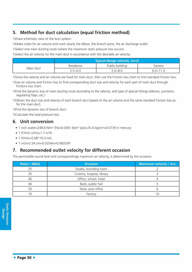
5. Method for duct calculation (equal friction method)1)Draw schematic view of the duct system.
1)Make notes for air volume and mark clearly the elbow, the branch parts, the air discharge outlet.
1)Select one main ducting route (where the maximum static pressure loss occurs).
1)Select the air velocity for the main duct in accordance with the desirable air velocity.
Typical design velocity (m/s)
Main ductResidence Public building Factory
3.5~6.0 5.0~8.0 6.0~11.0
1)Since the velocity and air volume are fixed for main duct, then use the Friction loss chart to find standard friction loss.
1)Use air volume and friction loss to find corresponding duct size and velocity for each part of main duct through frictions loss chart.
1)Find the dynamic loss of main ducting route according to the velocity. and type of special fittings (elbows, junctions, regulating flaps, etc.)
1)Obtain the duct size and velocity of each branch duct based on the air volume and the same standard friction loss as for the main duct.
1)Find the dynamic loss of branch duct.
1)Calculate the total pressure loss.
6. Unit conversion• 1 inch water=248.8 N/m2 (Pa)=0.0361 lb/in2 (psi)=25.4 kg/cm2=0.0739 in mercury
• 1 ft3/min (cfm)=1.7 m3/h
• 1 ft/min=5.08*10-3 m/s
• 1 inch=2.54 cm=0.0254m=0.08333ft
7. Recommended outlet velocity for different occasionThe permissible sound level and correspondingly maximum air velocity, is determined by the occasion.
Noise / dB(A) Occasion Maximum velocity / m/s
25 Studio, recording room 2
35 Cinema, hospital, library 3
40 Office, school, hotel 4
46 Bank, public hall 5
50 Store, post office 6
70 Factory 10

Contents
Troubleshooting
1. General Troubleshooting ....................................................................................52
2. Error Diagnosis and Troubleshooting Without Error Code ...............................53
2.1 Remote maintenance ...................................................................................53
2.2 Field maintenance .......................................................................................54
3. Troubleshooting ..................................................................................................58
3.1 Common Check Procedures.........................................................................59
3.2 Open circuit or short circuit of temperature sensor diagnosis and solution) . 60
3.3 Phase sequence error diagnosis and solution ...............................................61
3.4 Lack of Phase diagnosis and solution ...........................................................62
3.5 Overload current protection diagnosis and solution ......................................63
3.6 High temperature or protection of pressure diagnosis and solution ..............64

Trou
blesh
oo
ting
Page 52
1. General Troubleshooting
1.1 Error Display (Indoor Unit)
When the indoor unit encounters a recognized error, the indicator light will flash in a corresponding series, the timer display may turn on or begin flashing, and an error code will be displayed. These error codes are described in the following table:
LED1 LED2 LED3 Error Information Solution
OFF FLASH OFF T2 temperature sensor open or short circuit Page 60
FLASH OFF FLASH Wire control input error -
For other errors:
The display board may show a garbled code or a code undefined by the service manual. Ensure that this code is not a temperature reading.
Troubleshooting:
Test the unit using the remote control. If the unit does not respond to the remote, the indoor PCB requires replacement. If the unit responds, the display board requires replacement.
1.2 Error Display (Outdoor Unit Excluding MOV-48CN1-N)
LED1 LED2 LED3 Error Information Solution
Flash OFF OFF Phase sequence Page 61
Flash OFF OFF Lack of phase(A,B) Page 62
OFF OFF OFF Lack of phase(C) Page 62
Flash Flash OFF Protection of low pressure(only for MOV-60CN1-D) Page 64
off OFF Flash Overload current protection Page 63
OFF Flash OFFHigh temperature or protection of high pressure(only for MOV-60CN1-D)
Page 64

Tro
ub
lesh
oo
tin
g
Page 53
2. Error Diagnosis and Troubleshooting Without Error Code
WARNING
Be sure to turn off unit before any maintenance to prevent damage or injury.
2.1 Remote maintenance
SUGGESTION: When troubles occur, please check the following points with customers before field maintenance.
Problem Solution
1 Unit will not start Page 55-56
2 The power switch is on but fans will not start Page 55-56
3 The temperature on the display board cannot be set Page 55-56
4 Unit is on but the wind is not cold(hot) Page 55-56
5 Unit runs, but shortly stops Page 55-56
6 The unit starts up and stops frequently Page 55-56
7 Unit runs continuously but insufficient cooling(heating) Page 55-56
8 Cool can not change to heat Page 55-56
9 Unit is noisy Page 55-56

Trou
blesh
oo
ting
Page 54
2.2 Field maintenance
Problem Solution
1 Unit will not start Page 57-58
2 Compressor will not start but fans run Page 57-58
3 Compressor and condenser (outdoor) fan will not start Page 57-58
4 Evaporator (indoor) fan will not start Page 57-58
5 Condenser (Outdoor) fan will not start Page 57-58
6 Unit runs, but shortly stops Page 57-58
7 Compressor short-cycles due to overload Page 57-58
8 High discharge pressure Page 57-58
9 Low discharge pressure Page 57-58
10 High suction pressure Page 57-58
11 Low suction pressure Page 57-58
12 Unit runs continuously but insufficient cooling Page 57-58
13 Too cool Page 57-58
14 Compressor is noisy Page 57-58
15 Horizontal louver can not revolve Page 57-58

Tro
ub
lesh
oo
tin
g
Page 55
1.Remote Maintenance
Possible causes of trouble
Pow
er fa
ilure
The
mai
n po
wer
trip
ped
Loos
e co
nnec
tions
Faul
ty tr
ansf
orm
er
The
volta
ge is
too
high
or t
oo lo
w
The
rem
ote
cont
rol i
s pow
ered
off
Brok
en re
mot
e co
ntro
l
Dirt
y ai
r filt
er
Dirt
y co
nden
ser f
ins
The
setti
ng te
mpe
ratu
re is
hig
her/
low
er th
an th
ero
om's(
cool
ing/
heat
ing)
The
ambi
ent t
empe
ratu
re is
too
high
/low
whe
n th
em
ode
is co
olin
g/he
atin
g
Fan
mod
e
SILE
NCE
func
tion
is ac
tivat
ed(o
ptio
nal f
unct
ion)
Fros
ting
and
defr
ostin
g fr
eque
ntly
Unit will not start ☆ ☆ ☆ ☆
The power switch is on but fans will not start ☆ ☆ ☆
The temperature on the display board cannot be set ☆ ☆
Unit is on but the wind is not cold(hot) ☆ ☆ ☆
Unit runs, but shortly stops ☆ ☆ ☆
The unit starts up and stops frequently ☆ ☆ ☆
Unit runs continuously but insufficient cooling(heating) ☆ ☆ ☆ ☆ ☆
Cool can not change to heat
Unit is noisy
Test method / remedy
Test
vol
tage
Clos
e th
e po
wer
switc
h
Insp
ect c
onne
ctio
ns -
tight
en
Chan
ge th
e tr
ansf
orm
er
Test
vol
tage
Repl
ace
the
batte
ry o
f the
rem
ote
cont
rol
Repl
ace
the
rem
ote
cont
rol
Clea
n or
repl
ace
Clea
n
Adju
st th
e se
tting
tem
pera
ture
Turn
the
AC la
ter
Adju
st to
coo
l mod
e
Turn
off
SILE
NCE
func
tion.
Turn
the
AC la
ter
Refrigerant CircuitElectrical Circuit

Trou
blesh
oo
ting
Page 56
Heav
y lo
ad c
ondi
tion
Loos
en h
old
dow
n bo
lts a
nd /
or s
crew
s
Bad
airp
roof
The
air i
nlet
or o
utle
t of e
ither
uni
t is b
lock
ed
Inte
rfer
ence
from
cel
l pho
ne to
wer
s and
rem
ote
boos
ters
Ship
ping
pla
tes r
emai
n at
tach
ed
☆
☆
☆ ☆ ☆
☆ ☆
Chec
k he
at lo
ad
Tigh
ten
bolts
or s
crew
s
Clos
e al
l the
win
dow
s and
doo
rs
Rem
ove
the
obst
acle
s
Reco
nnec
t the
pow
er o
r pre
ss O
N/O
FFbu
tton
on re
mot
e co
ntro
l to
rest
art
Rem
ove
them
Others

Tro
ub
lesh
oo
tin
g
Page 57
2.Field Maintenance
Possible causes of trouble
Pow
er fa
ilure
Blow
n fu
se o
r var
istor
Loos
e co
nnec
tions
Shor
ted
or b
roke
n w
ires
Safe
ty d
evic
e op
ens
Faul
ty th
erm
osta
t / ro
om te
mpe
ratu
re se
nsor
Wro
ng se
tting
pla
ce o
f tem
pera
ture
sens
or
Faul
ty tr
ansf
orm
er
Shor
ted
or o
pen
capa
cito
r
Faul
ty m
agne
tic c
onta
ctor
for c
ompr
esso
r
Faul
ty m
agne
tic c
onta
ctor
for f
an
Low
vol
tage
Faul
ty st
eppi
ng m
otor
Shor
ted
or g
roun
ded
com
pres
sor
Shor
ted
or g
roun
ded
fan
mot
or
Unit will not start ☆ ☆ ☆ ☆ ☆ ☆
Compressor will not start but fans run ☆ ☆ ☆ ☆ ☆
Compressor and condenser (outdoor) fan will not start ☆ ☆ ☆
Evaporator (indoor) fan will not start ☆ ☆ ☆ ☆
Condenser (Outdoor) fan will not start ☆ ☆ ☆ ☆ ☆
Unit runs, but shortly stops ☆ ☆
Compressor short-cycles due to overload ☆ ☆
High discharge pressure
Low discharge pressure
High suction pressure
Low suction pressure
Unit runs continuously but insufficient cooling
Too cool ☆ ☆
Compressor is noisy
Horizontal louver can not revolve ☆ ☆ ☆
Test method / remedy
Test
vol
tage
Insp
ect f
use
type
& si
ze
Insp
ect c
onne
ctio
ns -
tight
en
Test
circ
uits
with
test
er
Test
con
tinui
ty o
f saf
ety
devi
ce
Test
con
tinui
ty o
f the
rmos
tat /
sens
or &
wiri
ng
Plac
e th
e te
mpe
ratu
re se
nsor
at t
he c
entr
al o
fth
e ai
r inl
et g
rille
Chec
k co
ntro
l circ
uit w
ith te
ster
Chec
k ca
paci
tor w
ith te
ster
Test
con
tinui
ty o
f coi
l & c
onta
cts
Test
con
tinui
ty o
f coi
l & c
onta
cts
Test
vol
tage
Repl
ace
the
step
ping
mot
or
Chec
k re
sista
nce
with
mul
timet
er
Chec
k re
sista
nce
with
mul
timet
er
Electrical Circuit

Trou
blesh
oo
ting
Page 58
Com
pres
sor s
tuck
Shor
tage
of r
efrig
eran
t
Rest
ricte
d liq
uid
line
Dirt
y ai
r filt
er
Dirt
y ev
apor
ator
coi
l
Insu
ffici
ent a
ir th
roug
h ev
apor
ator
coi
l
Ove
rcha
rge
of re
frig
eran
t
Dirt
y or
par
tially
blo
cked
con
dens
er
Air o
r inc
ompr
essib
le g
as in
refr
iger
ant c
ycle
Shor
t cyc
ling
of c
onde
nsin
g ai
r
High
tem
pera
ture
con
dens
ing
med
ium
Insu
ffici
ent c
onde
nsin
g m
ediu
m
Brok
en c
ompr
esso
r int
erna
l par
ts
Inef
ficie
nt c
ompr
esso
r
Expa
nsio
n va
lve
obst
ruct
ed
Expa
nsio
n va
lve
or c
apill
ary
tube
clo
sed
com
plet
ely
Leak
ing
pow
er e
lem
ent o
n ex
pans
ion
valv
e
Poor
inst
alla
tion
of fe
eler
bul
b
Heav
y lo
ad c
ondi
tion
Loos
en h
old
dow
n bo
lts a
nd /
or s
crew
s
Ship
ping
pla
tes r
emai
n at
tach
ed
Poor
cho
ices
of c
apac
ity
Cont
act o
f pip
ing
with
oth
er p
ipin
g or
ext
erna
l pla
te
☆
☆ ☆ ☆ ☆ ☆ ☆
☆ ☆ ☆
☆ ☆ ☆ ☆ ☆ ☆
☆ ☆
☆ ☆ ☆ ☆
☆ ☆ ☆ ☆ ☆ ☆ ☆ ☆
☆ ☆ ☆ ☆ ☆ ☆ ☆ ☆ ☆ ☆ ☆
☆ ☆ ☆ ☆ ☆
Repl
ace
the
com
pres
sor
Leak
test
Repl
ace
rest
ricte
d pa
rt
Clea
n or
repl
ace
Clea
n co
il
Chec
k fa
n
Chan
ge c
harg
ed re
frig
eran
t vol
ume
Clea
n co
nden
ser o
r rem
ove
obst
acle
Purg
e, e
vacu
ate
and
rech
arge
Rem
ove
obst
ruct
ion
to a
ir flo
w
Rem
ove
obst
ruct
ion
in a
ir or
wat
er fl
ow
Rem
ove
obst
ruct
ion
in a
ir or
wat
er fl
ow
Repl
ace
com
pres
sor
Test
com
pres
sor e
ffici
ency
Repl
ace
valv
e
Repl
ace
valv
e
Repl
ace
valv
e
Fix
feel
er b
ulb
Chec
k he
at lo
ad
Tigh
ten
bolts
or s
crew
s
Rem
ove
them
Choo
se A
C of
lage
r cap
acity
or a
dd th
e nu
mbe
rof
AC
Rect
ify p
ipin
g so
as n
ot to
con
tact
eac
h ot
her o
rw
ith e
xter
nal p
late
Refrigerant Circuit Others

Tro
ub
lesh
oo
tin
g
Page 59
3. Troubleshooting
3.1 Common Check Procedures
3.1.1 Temperature Sensor CheckDisconnect the temperature sensor from PCB, measure the resistance value with a tester.
Temperature Sensors.
Room temp.(T1) sensor,
Indoor coil temp.(T2) sensor,
Outdoor coil temp.(T3) sensor,
Outdoor ambient temp.(T4) sensor,
Compressor discharge temp.(Tp) sensor.
Measure the resistance value of each winding by using the multi-meter.

Trou
blesh
oo
ting
Page 60
3.2 Open circuit or short circuit of temperature sensor diagnosis and solution
Description: If the sampling voltage is lower than 0.06V or higher than 4.94V, the LED will display the failure.
Recommended parts to prepare:
• Wiring mistake
• Faulty sensor
• Faulty PCB
Troubleshooting and repair:
Check the connection between temperature sensor and PCB.
Replace the indoor main PCB
Is it within acceptable parameters?
Is it properly wired? Ensure proper connections.NO
Measure the resistance value of the sensor.
YES
Replace the Sensor.NO
YES

Tro
ub
lesh
oo
tin
g
Page 61
3.3 Phase sequence error diagnosis and solution
Description: Outdoor PCB detects the wrong phase sequence of 3-phase power supply.
Recommended parts to prepare:
• Wiring mistake of 3-phase power supply
• Faulty outdoor PCB
Troubleshooting and repair:
Phase sequence errorPhase sequence error
If malfunction is still not solved? If malfunction is still not solved?
Change the order of two of the wires to power supply.
Change the order of two of the wires to power supply.
YES
Replace the outdoor main PCBReplace the outdoor main PCB
Switch on the unit againSwitch on the unit again
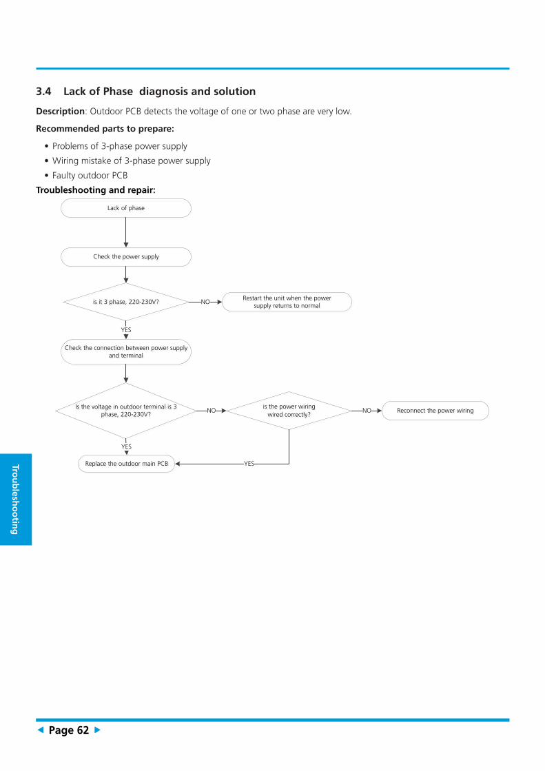
Trou
blesh
oo
ting
Page 62
3.4 Lack of Phase diagnosis and solution
Description: Outdoor PCB detects the voltage of one or two phase are very low.
Recommended parts to prepare:
• Problems of 3-phase power supply
• Wiring mistake of 3-phase power supply
• Faulty outdoor PCB
Troubleshooting and repair:
Lack of phaseLack of phase
YES
Replace the outdoor main PCBReplace the outdoor main PCB
is it 3 phase, 220-230V?is it 3 phase, 220-230V?
YES
Is the voltage in outdoor terminal is 3 phase, 220-230V?
Is the voltage in outdoor terminal is 3 phase, 220-230V?
Check the power supplyCheck the power supply
Check the connection between power supply and terminal
Check the connection between power supply and terminal
Restart the unit when the power supply returns to normal
Restart the unit when the power supply returns to normal
NO
Reconnect the power wiringReconnect the power wiringNO is the power wiring wired correctly?
is the power wiring wired correctly?
NO
YES

Tro
ub
lesh
oo
tin
g
Page 63
3.5 Overload current protection diagnosis and solution
Description: An abnormal current rise is detected by checking the specified current detection circuit.
Recommended parts to prepare:
• Power supply problems.
• System blockage
• Faulty PCB
• Wiring mistake
• Compressor malfunction
Troubleshooting and repair:
Check the power supply.
Do any exist?
Are they within acceptable parameters?
Are they properly connected?
Is it in working order?
Replace the outdoor unit.
Is it in working order?
Check system for blockages.
YES
Stop the unit.NO
Clear the blockage.NO
Check the compressor resistance values.
YES
Replace the compressor.NO
Check the connections and wires.
YES
Ensure proper connections or replace the wires.
NO
Check the reactor.
YES
YES
Replace the outdoor electronic control box.
NO

Trou
blesh
oo
ting
Page 64
3.6 High temperature or protection of pressure diagnosis and solution
Description: The High pressure switch detects a ultra high pressure or the Low pressure switch detects a ultra low switch, which could damage the system.
Recommended parts to prepare:
• Bad wiring of the pressure switches
• Faulty pressure switches
• Refrigeration system is over load or blocked or lack of refrigerant
Troubleshooting and repair:
High temperature or protection of pressure
High temperature or protection of pressure
Is temperature protective switch K1
open
Is temperature protective switch K1
open
Is it k1 or K2 open ?Is it k1 or K2 open ?
Possible reason1.The wires is loose to K12.Air or other gas in the refrigerant.3.Heat exchanger is dirty4.Outdoor fan or fan blade is defective5.Outdoor unit is in bad ventilation6.Refrigerant is leakage
Possible reason1.The wires is loose to K12.Air or other gas in the refrigerant.3.Heat exchanger is dirty4.Outdoor fan or fan blade is defective5.Outdoor unit is in bad ventilation6.Refrigerant is leakage
YES
Is pressure protective switch K2 open
Is pressure protective switch K2 open
Possible reason1.The wires is loose to K22.Air or other gas in the refrigerant.3.Heat exchanger is dirty4.Outdoor motor or fan blade is defective5.Outdoor unit is in bad ventilation6.Refrigerant is too much
Possible reason1.The wires is loose to K22.Air or other gas in the refrigerant.3.Heat exchanger is dirty4.Outdoor motor or fan blade is defective5.Outdoor unit is in bad ventilation6.Refrigerant is too much
YES

Page 65
Ind
ex
i) Temperature Sensor Resistance Value Table for T1, T2, T3, and T4 (°C – K) ....66
ii) Pressure On Service Port .....................................................................................67
Appendix

Trou
blesh
oo
ting
Page 66
i) Temperature Sensor Resistance Value Table for T1,T2,T3 and T4 (°C – K)°C °F K Ohm °C °F K Ohm °C °F K Ohm °C °F K Ohm-20 -4 115.266 20 68 12.6431 60 140 2.35774 100 212 0.62973
-19 -2 108.146 21 70 12.0561 61 142 2.27249 101 214 0.61148
-18 0 101.517 22 72 11.5 62 144 2.19073 102 216 0.59386
-17 1 96.3423 23 73 10.9731 63 145 2.11241 103 217 0.57683
-16 3 89.5865 24 75 10.4736 64 147 2.03732 104 219 0.56038
-15 5 84.219 25 77 10 65 149 1.96532 105 221 0.54448
-14 7 79.311 26 79 9.55074 66 151 1.89627 106 223 0.52912
-13 9 74.536 27 81 9.12445 67 153 1.83003 107 225 0.51426
-12 10 70.1698 28 82 8.71983 68 154 1.76647 108 226 0.49989
-11 12 66.0898 29 84 8.33566 69 156 1.70547 109 228 0.486
-10 14 62.2756 30 86 7.97078 70 158 1.64691 110 230 0.47256
-9 16 58.7079 31 88 7.62411 71 160 1.59068 111 232 0.45957
-8 18 56.3694 32 90 7.29464 72 162 1.53668 112 234 0.44699
-7 19 52.2438 33 91 6.98142 73 163 1.48481 113 235 0.43482
-6 21 49.3161 34 93 6.68355 74 165 1.43498 114 237 0.42304
-5 23 46.5725 35 95 6.40021 75 167 1.38703 115 239 0.41164
-4 25 44 36 97 6.13059 76 169 1.34105 116 241 0.4006
-3 27 41.5878 37 99 5.87359 77 171 1.29078 117 243 0.38991
-2 28 39.8239 38 100 5.62961 78 172 1.25423 118 244 0.37956
-1 30 37.1988 39 102 5.39689 79 174 1.2133 119 246 0.36954
0 32 35.2024 40 104 5.17519 80 176 1.17393 120 248 0.35982
1 34 33.3269 41 106 4.96392 81 178 1.13604 121 250 0.35042
2 36 31.5635 42 108 4.76253 82 180 1.09958 122 252 0.3413
3 37 29.9058 43 109 4.5705 83 181 1.06448 123 253 0.33246
4 39 28.3459 44 111 4.38736 84 183 1.03069 124 255 0.3239
5 41 26.8778 45 113 4.21263 85 185 0.99815 125 257 0.31559
6 43 25.4954 46 115 4.04589 86 187 0.96681 126 259 0.30754
7 45 24.1932 47 117 3.88673 87 189 0.93662 127 261 0.29974
8 46 22.5662 48 118 3.73476 88 190 0.90753 128 262 0.29216
9 48 21.8094 49 120 3.58962 89 192 0.8795 129 264 0.28482
10 50 20.7184 50 122 3.45097 90 194 0.85248 130 266 0.2777
11 52 19.6891 51 124 3.31847 91 196 0.82643 131 268 0.27078
12 54 18.7177 52 126 3.19183 92 198 0.80132 132 270 0.26408
13 55 17.8005 53 127 3.07075 93 199 0.77709 133 271 0.25757
14 57 16.9341 54 129 2.95896 94 201 0.75373 134 273 0.25125
15 59 16.1156 55 131 2.84421 95 203 0.73119 135 275 0.24512
16 61 15.3418 56 133 2.73823 96 205 0.70944 136 277 0.23916
17 63 14.6181 57 135 2.63682 97 207 0.68844 137 279 0.23338
18 64 13.918 58 136 2.53973 98 208 0.66818 138 280 0.22776
19 66 13.2631 59 138 2.44677 99 210 0.64862 139 282 0.22231

Tro
ub
lesh
oo
tin
g
Page 67
ii) Pressure On Service Port
Cooling chart:
°F(°C) ODT
IDT75 (23.89) 85 (29.44) 95 (35) 105 (40.56) 115 (46.11)
BAR 70/59 8.2 7.8 8.1 8.6 10.1
BAR 75/63 8.6 8.3 8.7 9.1 10.7
BAR 80/67 9.3 8.9 9.1 9.6 11.2
°F(°C) ODT
IDT75 (23.89) 85 (29.44) 95 (35) 105 (40.56) 115 (46.11)
PSI 70/59 119 113 117 125 147
PSI 75/63 124 120 126 132 155
PSI 80/67 135 129 132 140 162
°F(°C) ODT
IDT75 (23.89) 85 (29.44) 95 (35) 105 (40.56) 115 (46.11)
MPA 70/59 0.82 0.78 0.81 0.86 1.01
MPA 75/63 0.86 0.83 0.87 0.91 1.07
MPA 80/67 0.93 0.89 0.91 0.96 1.12