installation manual adamo - welcome to trane places in this installation manual. ... trane mcw...
TRANSCRIPT

ADAMO
Installation Manual
Split SystemWall TypeMCW Series 50 Hz
MS-SVN003-ENJanuary 2003
2 MS-SVN003-EN© American Standard Inc. 2003
General Information
General InformationThis Installation Manual is given as aguide to good practice in theinstallation by the installer of MCWmini-split system. Installationprocedures should be performed inthe sequence that they appear in thismanual.
For installing the unit to operateproperly and reliably, it must beinstalled in accordance with theseinstructions. Also, the services of aqualified service technician should beemployed, through the maintenancecontract with a reputable servicecompany.
Read this Installation Manualcompletely before installing theair conditioning system.
About This ManualCautions appear at appropriateplaces in this Installation Manual.Your personal safety and the properoperation of this machine require thatyou follow them carefully.The Trane Company assumes noliability for installations or servicingperformed by unqualified personnel.All phases of the installation of this airconditioning system must conform toall national, provincial, state and localcodes.
About The UnitThese MCW units are assembled,pressure tested, dehydrated, chargedand run tested before shipment. Theinformation contained in this manualapplies to MCW units are designed tooperate in cooling mode only.
Trane MCW series offer wall mountedinstallation to leave the floor spaceuncluttered, and equipped with LCDwireless remote control.
ReceptionOn arrival, inspect the unit beforesigning the delivery note. Specify anydamage of the unit on the deliverynote, and send a registered letter ofprotest to the last carrier of the goodswithin 72 hours of delivery. Notify thedealer at the same time.
The unit should be totally inspectedwithin 7 days of delivery. If anyconcealed damage is discovered,send a registered letter of protest tothe carrier within 7 days of deliveryand notify the dealer.
WarningWarnings are provided at appropriateplaces in this manual to indicate toinstallers, operators and servicepersonnel of potentially hazardoussituations which, if not avoided,COULD result in death or seriousinjury.
CautionCautions are provided at appropriateplaces in this manual to indicate toinstallers, operators, and servicepersonnel of potentially hazardoussituations which, if not avoided, MAYresult in minor or moderate injury ormalfunction of the unit.
Your personal safety and the properoperation of this unit require that youfollow them carefully. The TraneCompany assumes no liability forinstallations or servicing performed byunqualified personnel.
WarrantyWarranty is based on the generalterms and conditions by country. Thewarranty is void if the equipment ismodified or repaired without thewritten approval of The TraneCompany, if the operating limits areexceeded or if the control system orthe electrical wiring is modified.
Damage due to inappropriateinstallation, lack of knowledge orfailure to comply with themanufacturer’s instructions, is notcovered by the warranty obligation.If the installation does not conform tothe rules described in InstallationManual, it may entail cancellation ofwarranty and liabilities by The TraneCompany.
ImportantThis document is customer propertyand is to remain with unit. Pleaseplace in service information pack uponcompletion of work.These instructions do not cover allvariations in systems, nor do theyprovide for every possible contingencyto be met in connection withinstallation.Should further information be desiredor should particular problems arisewhich are not covered sufficiently inthis manual, the matter should bereferred to your authorized Tranedealer.
MS-SVN003-EN 3
Contents
General Information 2
Typical Installation 4
Location and Preparation of Unit 5
Unit Installation 6
Wiring Diagram 12
Dimensional Data 13
Notes 14
4 MS-SVN003-EN
Typical Installation
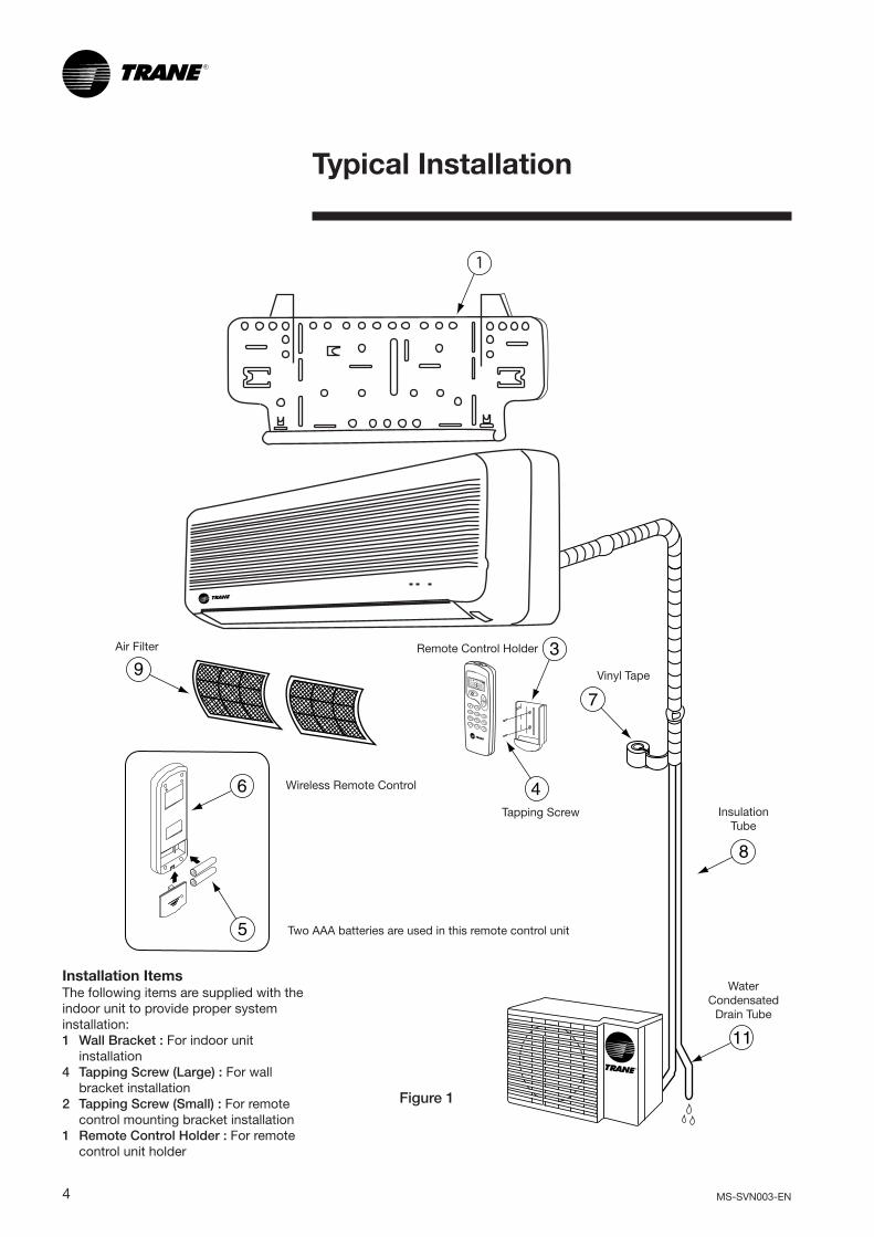
Figure 1
InsulationTube
Tapping Screw
Remote Control Holder
Vinyl Tape
Two AAA batteries are used in this remote control unit
Wireless Remote Control
Air Filter
WaterCondensated
Drain Tube
Installation ItemsThe following items are supplied with theindoor unit to provide proper systeminstallation:1 Wall Bracket : For indoor unit
installation4 Tapping Screw (Large) : For wall
bracket installation2 Tapping Screw (Small) : For remote
control mounting bracket installation1 Remote Control Holder : For remote
control unit holder
ON OFF

MS-SVN003-EN 5
Location and Preparation of Unit
Figure 2
100 mm.
50 m
m.
100 mm.
500
mm
.
Figure 3
25 cm. or more
60 cm. or more
25 cm. or more
120 cm. or more
30 cm. or more
Selecting the MountingLocationsDetermine the mounting location withthe customer as follows:
Indoor Unit• Install the indoor unit level on a
strong wall which is not subjectto vibration.
• The inlet and outlet ports shouldnot be obstructed. The air shouldbe able to blow throughout theroom.
• Install the indoor unit whereconnection to the outdoor unitcan be made easily.
• Install the unit where the drain pipecan be easily installed.
• Take servicing into considerationand leave the spacing shown inFigure 2. Also, install the unit wherethe filter can be easily removed.
• Do not install the unit near a sourceof heat, steam, or flammable gas.
• Do not install the unit where it willbe exposed to direct sunlight.
Outdoor Unit• Leave the spacing shown in
Figure 3 for required air flow.• If possible, do not install the unit
where it will be exposed to directsunlight.
• Do not install the unit near a sourceof heat, steam, or flammable gas.
• Do not install the unit where astrong wind consistently blows orwhere it is extremely dusty.
• Do not install the unit where peoplepass in front of the fan dischargegrille.
General Instructions• All phases of the installation of this
air conditioning system mustconform to all national, provincial,state and local codes.
• Read these instructions carefullyand completely before attemptingto install the air conditioningsystem.
• For the air conditioning system tooperate properly and reliably, itmust be installed in accordancewith these instructions.
• The maximum length of the pipingis to10 meters. If the units arefurther apart than this, correctoperation can not be guaranteed.

6 MS-SVN003-EN
Unit Installation
Figure 4
2.Left rearoutlet
3.Left outlet
4.Right outlet
(Rear)
1.Rear outlet5.Bottom
outlet
Figure 6
Figure 5
Counter Weight
Type A Screw
Marking-off Line
Indoor Unit InstallationThe piping can be connected in thefive directions indicated by 1, 2, 3, 4and 5 in Figure 4. When the piping isconnected in direction 3, 4 or 5 cutalong the piping groove in the side orbottom of the front cover with a saw.
1. Installing the Wall Bracket1. Install the wall bracket so that it
is level from side to side. If thewall bracket is tilted, condensatewater will drip to the floor.
2. Install the wall bracket so that itis strong enough to withstand aweight of 50 kilograms or more.
3. Fasten the wall bracket to thewall with 6 or more screwsthrough the holes near the outeredge of the bracket.
4. Check to insure that there is norattle of the wall bracket againstthe wall.
Caution• Always cut the wall hole uniformly
and straight when the wall pipe isnot used. If the hold center is notaligned, condensate leakage canoccur.
• If the wall pipe is not used, thewiring cable connecting the indoorand outdoor units may becomefrayed and cause electric currentleakage to earth.
3. Forming the Indoor DrainHose and Refrigerant Pipes1. For 3 Left piping. 4 Right piping,
5 Bottom piping: Perform.“Indoor Unit Wiring” beforeperforming the following steps3.2 through 3.6.
2. Wrap the pipes of the indoor unitthat are visible from the insidewith decorative tape (Figure 7).
3. Insert the indoor unit piping intothe wall hole and bind the drainhose and pipe together withvinyl tape (Figure 8).
2. Cutting the Hole in the Wallfor the Connecting Piping1. Cut a 65 mm. diameter hole in
the wall at the desired positionshown in Figure 6.
2. Cut the hole so that the outsideend is lower (5-10 mm.) than theinside end.
3. Cut the wall pipe length to matchthe wall thickness, insert it intoan accessory wall cap, fasten thecap with vinyl tape, and insert thepipe through the wall hole. (Wallpipe and wall cap are procuredat the site).
4. For 3 left piping and 4 rightpiping, cut the hole sligthly lowerso that the condensate water willflow freely.
Installation Plate
Thread
MCW509-512
MCW518-524

MS-SVN003-EN 7
Figure 10
Drain hose Wall holepipe
PipeConnection
cable
Figure 7
ConnectioncableDrain hose
Decorative tape
Left piping
Left rear pipingBottom piping
Right piping
Cut the piping groovewith a hacksaw
Cut the piping groovewith a hacksaw
(Rear)
Indoor unitpiping
For left outlet, house the connection cordand piping at the position shown in the abovefigure with the drain hose at the bottom.
Figure 11
4. Install the piping so that the drainhose is at the bottom (Figure 7).
Caution• To prevent breaking of the pipe,
avoid sharp bends. Bend thepipe with a radius of curveture of100 mm. or more.
• If the pipe is bent repeatedly at thesame place, it will break.
• Do not remove the flare nutsfrom the indoor unit pipe untilimmediately before connectingthe outdoor connection piping.
5. After passing the indoor pipingand drain hose through the wallhole, hang the indoor unit on thehooks at the top and bottom ofthe wall bracket.
6. Check to insure that: (Ref.Figure 10).
• The top and bottom hooks arehooked firmly and the indoor unitdoes not move to the front andrear or left and right.
• The indoor unit is accuratelypositioned horizontally andvertically.
• The drain hose is at the bottomof the wall hole pipe.
Indoor Unit WiringBoth of the cable wires should beconnect from the terminal blockof indoor unit (Figure 11).
• The appliance shall be installed inaccordance with national wiringregulation.
• Means for disconnection from thesupply having a contact separationof at least 3 mm. in all poles mustbe incorporated in the field wiring.
Figure 9
After hooking the indoor unit to the tophook, hook the fitting of the indoor unit tothe two bottom hooks while lowering theunit and pushing it against the wall.
Wall hookbracket
Indoor unit
(Rear)
(Fitting)Bottom hooks
Tophooks
Figure 8
Drain hose(bottom)
Bind withvinyl tape
Pipe (top)
(Rear)

8 MS-SVN003-EN
A good flare should have thefollowing characteristics:- Inside surface is glossy and
smooth.- Edge is smooth.- Tapered sides are of uniform
length.
Bending5. When bending the tube, be careful
not to crush it. To prevent crushingof the tube, bend it gently and donot bend the tube at a radiuscurvature of less than 100 mm.
3. Remove the flare nut from theunit and be sure to mount it onthe copper tube.
4. Make a flare at the end of coppertube with a flare tool (Figure 14,15).
Outdoor Unit Installation1. Install the unit mounting pads
(4 places) into the bottom channelsby tapping gently with a plastic orrubber tipped hammer.
2. Set the unit on a strong surfacesuch as one made of concrete tominimize shock and vibration andto locate the unit securely.
3. Do not set the unit directly on the
ground.
Connecting the Unit withFlaring Procedure.Flaring (If piping is procured or cut atthe site).
1. Cut the copper tube to therequired length with a tube cutter.It is recommended to cut approx.30-50 cm. longer than the tubinglength you estimate.
2. Hold each pipe downward whencutting and remove burrs at theend of the copper tube with a tubereamer or file. This process isimportant and should be donecarefully to make a good flare(Figure 12 and Figure 13).
Flare nut
Copper tubing
Flare tool
Figure 14
Figure 15
L
Check if (L) is flared uniformand is not cracked or scratched.L Dimension:
1.4 to 1.7 mm (6.35 mm dia)1.8 to 2.0 mm (9.53 mm dia)1.9 to 2.2 mm (12.7 mm dia)2.1 to 2.4 mm (15.88 mm dia)
Figure 12
Coppertubing Reamer
Figure 13
Deburring
Before After
6. If the copper tube is bent or pulledtoo often, it will become stiff. Donot bend the pipe more than threetimes at one place.
Cautions before ConnectingTubes Tightly7. Be sure to apply a sealing cap
or water-proof tape to preventdust or water from getting intothe tubes before they are used.
8. Be sure to apply refrigerantlubricant to the matchingsurfaces of the flare and unionbefore connecting them together.This is effective for reducing gasleaks (Figure 16).
Figure 16
Apply refrigerant lubricant here
Figure 17
Union Flare nut
Connection9. For proper connection, align the
union tube and flare tube straightwith each other, then screw in theflare nut lightly at first to obtain asmooth match (Figure 17).
When reaming, hold the tube enddownward and be sure that nocopper scraps fall into the tube.
10. Tighten the flare nut to thespecified tightening torque withtorque wrench and adjustablewrench (Figure 18).
11. Repeat the process above for theremaining line.

MS-SVN003-EN 9
Indoor unit pipe
Torque wrench
Flare nutConnection pipe
Wrench(adjustable).
Figure 18
Flare Nut Tightening Torque
Flare nut/Piping size Tightening torquekgf, - cm lbf-in
6.35 mm (1/4”) dia. 150~200 130~170
9.53 mm (3/8”) dia. 350~400 300~340
12.7 mm (1/2”) dia. 500~550 430~470
15.88 mm (5/8”) dia. 600~650 520~570
Remote Control InstallationLocate and attach the wirelessremote control as follows:1. Do not place the control and the
remote control near heat sourcesor expose to the direct rays of thesun.
2. Do not expose the control to theindoor unit’s supply air stream.
3. Do not place in a confined space.4. Attach the remote control holder
as shown in Figure 19.
Evacuation and RefrigerantCharge1. Air Evacuation and Charging
1. Remove the cap and connect thegauge manifold and the vacuumpump to the charging port usingthe service hoses (Figure 20).
2. Pump the indoor unit and theconnecting pipes until thepressure in them lowers to below1.5 mmHg of vacuum.
3. Stop the vacuum pump and closethe gauge manifold valve.
4. Remove the blanking caps andfully open the service valves witha hexagon wrench (Torque: 70to 90 kgf - cm).
RemoteControl
Unit
ON OFF
Remote Control Holder
Tapping Screw(small)
Wireless Remote ControlFigure 19

10 MS-SVN003-EN
Figure 22
Pipe length 16ft 23ft 33ft(5m) (7m) (10m)
Additional refrigerant None 1.1 oz 2.8 oz(R22) (32g) (80g)
5. Reinstall the blanking caps of theservice valves.
6. Disconnect the service hoses andreinstall the cap on the chargingport. (Tightening torque: 70 to90 kgf - cm).
2. Additional ChargeRefrigerant suitable for a piping lengthof 3.5 to 5.0 meters is charged in theoutdoor unit from the factory. When thepiping is longer than 5 m, additionalcharging is necessary. For theadditional amount, see table below.
Outdoor Unit
Figure 20
Refrigerant pipe
Blank cap
Charging port
Cap
Service hosewith valve core
Service valve
Gauge manifold
Vacuumpump
Service hose
Between 5 m and 10 m, when usingconnection pipe lengths other thanthat in the table, charge additionalrefrigerant with 0.56 oz (16g)/3.3ft.
Caution• FREON GAS “R22” ONLY• Always evacuate air from the piping
before adding refrigerant.• Add refrigerant through the
charging valve after the completionof removing the blanking caps andfully open the service valves.
Gas Leakage InspectionAfter charging with refrigerant, checkthe joints for gas leakage with gas leakdetector or a soap bubble solution.
Figure 21
Outdoor Unit Wiring1. Remove the outdoor unit terminal
cover (Figure 21).2. Route the connection cable through
the cable entry brushing and up tothe terminal block.
3. Insert the end of the cable wiresinto the terminal block connectorsas shown on the unit wiringdiagram (Figure 11).
4. Tighten the terminal blockconnector screws.(Torque: 7-12 kgf-cm).
• The appliance shall be installed inaccordance with national wiringregulation.
Caution• The connector cable wires must be
connected such that terminalnumbers on the indoor unit matchthose on the terminal block of theoutdoor unit (Figure 11).
• Insert the connection cable wiresinto the terminal block firmly.Incorrect insertion may cause asafety problem.
5. Replace the outdoor unit terminalcover.
Drain hose
MS-SVN003-EN 11
Figure 23
Pipe
ClampWall
Outside wallcap sealer
(Outdoor)
End in water
Figure 24
Check the following:
Drain hose
Clamp
Lifted up
Wave
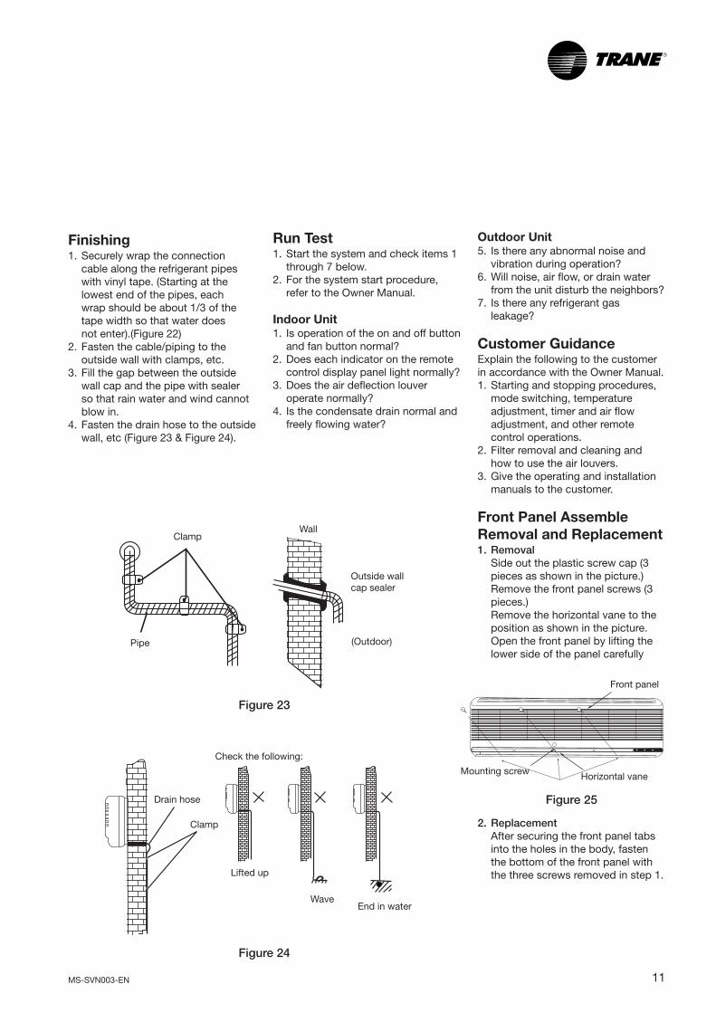
Finishing1. Securely wrap the connection
cable along the refrigerant pipeswith vinyl tape. (Starting at thelowest end of the pipes, eachwrap should be about 1/3 of thetape width so that water doesnot enter).(Figure 22)
2. Fasten the cable/piping to theoutside wall with clamps, etc.
3. Fill the gap between the outsidewall cap and the pipe with sealerso that rain water and wind cannotblow in.
4. Fasten the drain hose to the outsidewall, etc (Figure 23 & Figure 24).
Run Test1. Start the system and check items 1
through 7 below.2. For the system start procedure,
refer to the Owner Manual.
Indoor Unit1. Is operation of the on and off button
and fan button normal?2. Does each indicator on the remote
control display panel light normally?3. Does the air deflection louver
operate normally?4. Is the condensate drain normal and
freely flowing water?
Outdoor Unit5. Is there any abnormal noise and
vibration during operation?6. Will noise, air flow, or drain water
from the unit disturb the neighbors?7. Is there any refrigerant gas
leakage?
Customer GuidanceExplain the following to the customerin accordance with the Owner Manual.1. Starting and stopping procedures,
mode switching, temperatureadjustment, timer and air flowadjustment, and other remotecontrol operations.
2. Filter removal and cleaning andhow to use the air louvers.
3. Give the operating and installationmanuals to the customer.
Front Panel AssembleRemoval and Replacement1. Removal
Side out the plastic screw cap (3pieces as shown in the picture.)Remove the front panel screws (3pieces.)Remove the horizontal vane to theposition as shown in the picture.Open the front panel by lifting thelower side of the panel carefully
2. ReplacementAfter securing the front panel tabsinto the holes in the body, fastenthe bottom of the front panel withthe three screws removed in step 1.
Front panel
Mounting screw Horizontal vane
Figure 25
12 MS-SVN003-EN
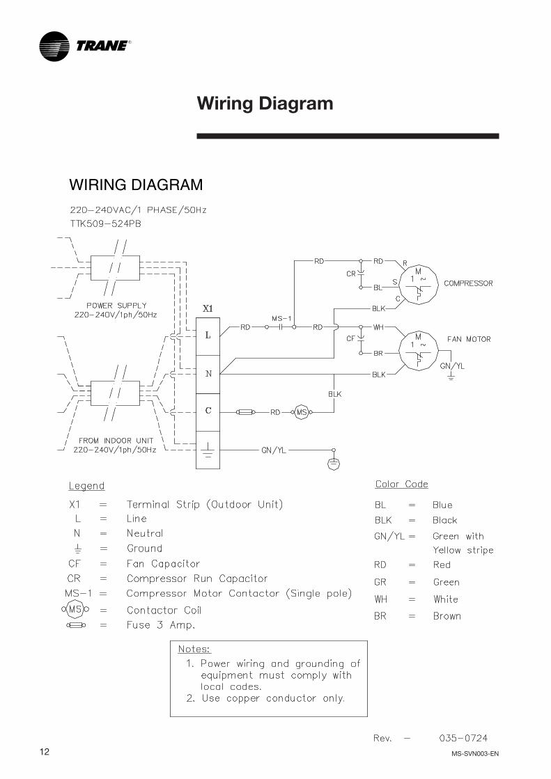
Wiring Diagram

MS-SVN003-EN 13
Dimensional Data
MODEL DIMENSIONS (MM.) CLEARANCE (MM.) WEIGHT (KG.)
A B C D E F
MCW 5097BA00 900.00 180.00 265.00 10.00
MCW 5127BA00 900.00 180.00 265.00 100.00 50.00 500.00 10.00
MCW 5187BA00 1,165.00 180.00 310.00 14.00
MCW 5247BA00 1,165.00 180.00 310.00 14.00
AD
F
D
B
C
E

14 MS-SVN003-EN
Notes
MS-SVN003-EN 15
Notes

Since The Trane Company has a policy of continuous product and product data improvement,it reserves the right to change design and specifications without notice.
Literature Order Number: MS-SVN003-EN 0103
Supersedes: MS-SVN003-EN 1200
Stocking Location: Bangkok, Thailand
Trane Thailand7th Floor, Ploenchit Center Building2 Sukhumvit Road, KlongtoeyBangkok 10110
Amair Limited35 Mu 8, Poochaosamingprai RoadSamrong Tai, Samutprakarn 10130
http://www.trane.comAn American Standard Company
∫√‘…—∑ ·Õ¡·Õ√å ®”°—¥ 35 À¡Ÿà 8 ∂.ªŸÉ‡®â“ ¡‘ßæ√“¬ µ. ”‚√ß„µâ Õ.æ√–ª√–·¥ß ®. ¡ÿ∑√ª√“°“√ 10130