installation guide - heating and air conditioning … bas-svn003-e4 3 about this manual these...
TRANSCRIPT

Tracer ZN523 Zone Controller
InstallationGuide
BAS-SVN003-E4

Contents
BAS-SVN003-E4
IntroductionAbout this manual 3
Controller description 4
Typical network architecture 5
Hardware inspection 6
Mounting and wiringZN523 mounting recommendations 7
ZN523 power supply recommendations 8
ZN523 inputs wiring recommendations and restrictions 9
ZN523 outputs wiring recommendations 10
Trane communicating zone sensor mounting 12
Trane communicating zone sensor wiring 13
Network layout 14
InstallationElectrical connection: Power supply and binary outputs 17
Electrical connection: Inputs 21
Electrical connection: Trane communicating zone sensor 22
Electrical connection: Communication link 23
Installation check-up
Configuration
Appendix
© 2009 Trane

Introduction
3BAS-SVN003-E4
About this manualThese instructions are given as a guide to good practice in the installationof Trane ZN523 LonMark® control. They do not contain the full serviceprocedures necessary for the continued successful operation of thisequipment. The services of a qualified service technician should beemployed through a maintenance contract with a reputable servicecompany. Cautions appear at appropriate places in this instruction manual.Your personal safety and the proper operation of this machine require thatyou follow them carefully. The constructor assumes no liability forinstallations or servicing performed by unqualified personnel.
Figure 1: Installation guide use
1
2
3
4
5
DISCOVER ZN523 ZONE CONTROLLER
INTRODUCTION: CONTROLLER DESCRIPTIONINTRODUCTION: TYPICAL NETWORK ARCHITECTURE
CHECK DEVICE RECEPTION
INTRODUCTION: HARDWARE INSPECTION
BEFORE INSTALLATION
MOUNTING & WIRING: ZN523 MOUNTING RECOMMENDATIONSMOUNTING & WIRING: ZN523 POWER SUPPLY WIRING RECOMMENDATIONSMOUNTING & WIRING: ZN523 INPUTS WIRING RECOMMENDATIONSMOUNTING & WIRING: ZN523 OUTPUTS WIRING RECOMMENDATIONSMOUNTING & WIRING: ZN523 COMMUNICATING ZONE SENSOR MOUNTING RECOMMENDATIONSMOUNTING & WIRING: ZN523 COMMUNICATING ZONE SENSOR WIRING RECOMMENDATIONSMOUNTING & WIRING: NETWORK LAYOUT
INSTALL ZN523
ELECTRICAL CONNECTIONS: BINARY OUTPUTSELECTRICAL CONNECTIONS: INPUTSELECTRICAL CONNECTIONS: TRANE COMMUNICATING ZONE SENSORELECTRICAL CONNECTIONS: COMMUNICATION LINKELECTRICAL CONNECTIONS: POWER SUPPLY
VALIDATE ZN523 INSTALLATION
INSTALLATION CHECK-UP: ZN523 INSTALLATION CHECK-LIST

Introduction
BAS-SVN003-E44
Controller descriptionThe ZN523 unit controller is a microprocessor-based direct digital controllerthat is dedicated to the control and the optimization of chilled waterterminal units.
ZN523 is designed to provide improved comfort with minimum energyconsumption.
The controller uses the measured space temperature as well as dischargeair temperature (in cascade control mode) and a control algorithmmaintains space temperature at the active cooling setpoint (in coolingmode) or the active heating setpoint (in heating mode) while driving the fanat the lowest possible speed.
• LonMark® HVAC Space Comfort Controller profile 8501.• Up to 3-speed fan motor control capability.• Supports various configurations: 2 pipes cooling only, 2 pipes heating
only, 2 pipes change over, 2 pipes change over + electric heat, 2 pipescooling + electric heat, 4 pipes, chilled beam.
• Cascade Proportional Integral control loop space / supply airtemperature, or single PI control loop for low profile applications.
• Intelligent 3-speed fan control for acoustic comfort.• Pre-engineered Master / Slave capability for easy wall, floor arrangement
changes.• Automatic diagnostics control: sensor failure, freeze protection,
condensate overflow, dirty filter.• Designed for field and factory installation.• Support of hot wax or 3 floating points valve actuators.• Direct connection to fan.• Direct control of electric heater (embedded relay with capacity of up to
1.8 kW).• Capability of driving an external solid state relay for electric heater.• Multiple mode of operation for occupancy conditions. (occupied /
unoccupied / standby).• PWM control of hot wax valves actuators.• PWM control of electric heater.• Automatic Change Over.• Entering water temperature sampling in 2-way valves applications types.• 230 Vac power supply.
When provided as a factory installed controller, Trane ZN523 is setup andtested during the assembly process and is ready to run when delivered tothe customer's site.
The use of a commissioning software, so called Trane Rover service tool, isrequired to adjust the various parameters of the controller.

Introduction
5BAS-SVN003-E4
Typical network architectureThe Tracer zone controllers shown in the figure below can operate on aTracer SummitTM building automation system, on a peer-to-peer network oras stand-alone devices.
Figure 2 - ZN523 network architecture
1. Tracer SummitTM Building Control Unit.2. Terminal unit + ZN523.3. Trane communicating zone sensor module.M. ZN523 controller with zone sensorS. ZN523 controller without zone sensorZ. Zone.
Workstation�
LAN (Ethernet or ARCNET)�
BACnet protocol�
FT
T 1
0A to
polo
gy�
LonW
orks
- L
onT
alk
prot
ocol
�
S� S�
M� S� M� S�
1�
2�
ZA�
ZC�ZB�
M�
3�

Introduction
BAS-SVN003-E46
Hardware inspection
Warranty
Warranty is based on Trane general terms and conditions. The warranty isvoid if the equipment is modified or repaired without the written approvalof the constructor, if the operating limits are exceeded, or if the controlsystem or the electrical wiring is modified. Damage due to misuse, lack ofmaintenance or failure to comply with the manufacturer's instructions is notcovered by the warranty obligation. If the user does not conform to theinstructions given in this document, it may entail cancellation of warrantyand liabilities by the constructor.
Reception
On arrival, inspect the unit before signing the delivery note. Specify anyvisible damage on the delivery note, and send a registered letter of protestto the last carrier of the goods within 72 hours of delivery. Notify the localTrane sales office at the same time. The delivery note must be clearlysigned and countersigned by the driver. Any concealed damage shall benotified by a registered letter of protest to the last carrier of the goodswithin 72 hours of delivery. Notify the local Trane sales office at the sametime.
Important notice: No shipping claims will be accepted by Trane if the abovementioned procedure is not respected.
Note: More stringent national rules can apply in some countries.
For more information, refer to the general sales conditions of your localTrane sales office.

Mounting and wiring
7BAS-SVN003-E4
ZN523 mounting recommendationsTo mount the ZN523 unit controller:• Select a location, near the controlled equipment to reduce wiring costs,
and EMC disturbance risks.• Verify that the location conforms to the specifications below.• Secure the controller to a 35 mm DIN rail. (Use only 10/10 mm thickness
sheet).
Figure 3 - ZN523 mounting
Table 1 - ZN523 unit controller specifications
Board dimensions 95 mm height x 132 mm width x 56 mm depthMinimum clearances Front 100 mm
Each side 25 mmTop and bottom 100 mm
Operating environment Temperature: from 0° to 60°CRelative Humidity: from 5% to 95% non-condensingDust protection: pollution level 1
Storage environment Temperature: from -40° to 85°CRelative Humidity: from 5% to 95% non-condensing

Mounting and wiring
BAS-SVN003-E48
ZN523 Power Supply recommendationsThe ZN523 unit controller is powered by 230 Vac. A 3-wire quick-connectterminal (TB3) is provided for 230 Vac connection to the board.
To ensure the controller will operate properly, verify that the power supplycircuit is in compliance with the following circuit requirements:
Table 2 - Power supply recommendations
Power requirements 230 Vac (+10%/-15%)50 or 60 Hz3 A maximum (all outputs utilized)
Protection The unit controller must receive power from a dedicated circuit, itmust be protected by a 3 A circuit breaker/fuse located next to it.
The electric heater (when present ) must receive power from adedicated circuit, it must be protected by a circuit breaker/fuselocated next to it (value dependant on electric heater capacity).
Recommended wire The AC-power wiring requires three-wire 230 Vac service.The recommended wire is 16 AWG (1.5mm2) copper wire.
Standards The AC-power wiring must comply with applicable local electricalcodes.
89/336/EEC European directive for electromagnetic compatibility:- Immunity: 61000-6-1- Emission: 61000-6-3
73/23/EEC European directive for low voltage electrical equipment:- EN 60335-1- EN 60335-2-40
Mounting and wiring
9BAS-SVN003-E4
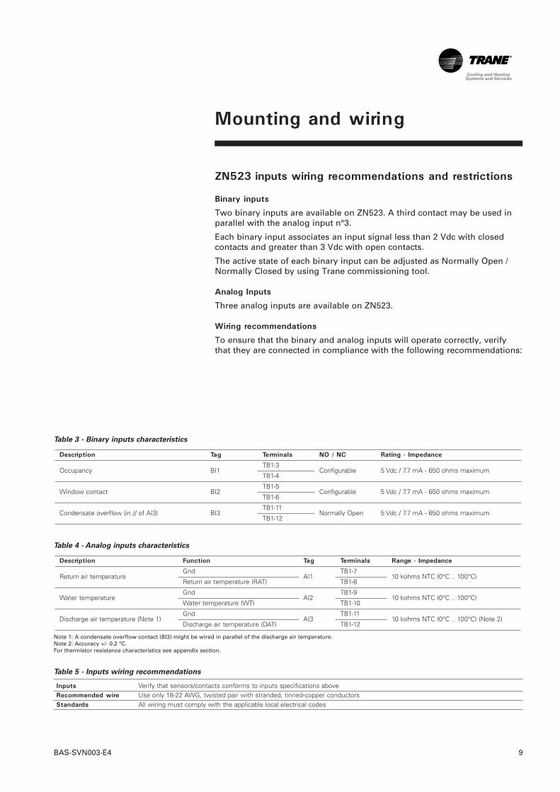
ZN523 inputs wiring recommendations and restrictions
Binary inputs
Two binary inputs are available on ZN523. A third contact may be used inparallel with the analog input n°3.
Each binary input associates an input signal less than 2 Vdc with closedcontacts and greater than 3 Vdc with open contacts.
The active state of each binary input can be adjusted as Normally Open /Normally Closed by using Trane commissioning tool.
Analog Inputs
Three analog inputs are available on ZN523.
Wiring recommendations
To ensure that the binary and analog inputs will operate correctly, verifythat they are connected in compliance with the following recommendations:
Table 3 - Binary inputs characteristics
Table 4 - Analog inputs characteristics
Note 1: A condensate overflow contact (BI3) might be wired in parallel of the discharge air temperature.Note 2: Accuracy +/- 0.2 °C.For thermistor resistance characteristics see appendix section.
Table 5 - Inputs wiring recommendations
Inputs Verify that sensors/contacts conforms to inputs specifications aboveRecommended wire Use only 18-22 AWG, twisted pair with stranded, tinned-copper conductorsStandards All wiring must comply with the applicable local electrical codes
Description Function Tag Terminals Range - Impedance
Return air temperatureGnd
AI1TB1-7
10 kohms NTC (0°C .. 100°C)Return air temperature (RAT) TB1-8
Water temperatureGnd
AI2TB1-9
10 kohms NTC (0°C .. 100°C)Water temperature (WT) TB1-10
Discharge air temperature (Note 1)Gnd
AI3TB1-11
10 kohms NTC (0°C .. 100°C) (Note 2)Discharge air temperature (DAT) TB1-12
Description Tag Terminals NO / NC Rating - Impedance
Occupancy BI1TB1-3
Configurable 5 Vdc / 7.7 mA - 650 ohms maximumTB1-4
Window contact BI2TB1-5
Configurable 5 Vdc / 7.7 mA - 650 ohms maximumTB1-6
Condensate overflow (in // of AI3) BI3TB1-11
Normally Open 5 Vdc / 7.7 mA - 650 ohms maximumTB1-12

Mounting and wiring
BAS-SVN003-E410
ZN523 outputs wiring recommendationsEight binary outputs are available on ZN523:• 3 for fan motor speed control.• 2 for cooling valve actuator control.• 2 for heating valves actuator control.• 1 for electric heater control.
Table 6 - Binary outputs characteristics
Note 1: Current peak must not exceed 0,8A during 20msNote 2: See table 8 for solid state relay characteristics, minimum triac PWM cycle time is 10 seconds.Note 3: TB5 is a 2 points screw connector (torque 0,5 Nm). Minimum relay PWM cycle time is 360 seconds.
Table 7- Typical valve actuator wiring
Actuator type Cooling valve Heating valveThermal (hot wax) TB2-5, TB2-6 TB2-8, TB2-93 floating points TB2-5, TB2-6, TB2-7 TB2-8, TB2-9, TB2-10
Table 8 - Solid state relays characteristics
Switching mode Rated operational voltage Control voltage Rated operational current Input ImpedanceZero switching 230 Vac rms 230 Vac From 2 A to 40 A (Note 1) 60 kohms
Note 1: Electric heater from 500 W to 10 kWNote 2: See appendix for solid state relay suggestions.
Description Function Tag Terminals Output type Output Rating
Fan
Fan high BO1 TB2-1 Relay 230 Vac, max 3 A
Fan medium BO2 TB2-2 Relay 230 Vac, max 3 A
Fan Low BO3 TB2-3 Relay 230 Vac, max 3 A
Fan neutral TB2-4
Cool valve
Cool open BO4 TB2-5 Triac 230 Vac, max 0.3 A (Note 1)
Cool neutral TB2-6
Cool close BO5 TB2-7 Triac 230 Vac, max 0.3 A (Note 1)
Heat valve
Heat open BO6 TB2-8 Triac 230 Vac, max 0.3 A (Note 1)
Heat neutral TB2-9
Heat close BO7 TB2-10 Triac 230 Vac, max 0.3 A (Note 1)
Electric heat (triac) + solid state relay
Electric heat BO6 TB2-8 Triac 230 Vac, max 0.3 A (Note 2)
Electric heat neutral TB2-9 This output must drive a solid state relay
Electric heat (relay)Electric heat BO8 TB5-2 Relay 1.8 kW at 230 Vac max (note 3)
Electric heat neutral TB5-1

Table 9: ZN523 output assignment.
Fan high TB2-1 x x x x x x x xFan medium TB2-2 x x x x x x x xFan low TB2-3 x x x x x x x xFan neutral TB2-4 x x x x x x x xCool open TB2-5 x x x x x x x x xCool neutral TB2-6 x x x x x x x x xCool close TB2-7 x x x x x x x x xHeat open TB2-8 x xHeat neutral TB2-9 x xHeat close TB2-10 x xCool open TB2-5 x x x x x x xCool neutral TB2-6 x x x x x x xHeat open TB2-8 x xHeat neutral TB2-9 x xElectric heat TB5-2 x x xElectric heat neutral TB5-1 x x xElectric heat TB2-8 x x xElectric heat neutral TB2-9 x x x
Mounting and wiring
11BAS-SVN003-E4
Wiring recommendations
To ensure that outputs will operate correctly, verify that they are connectedin compliance with the following recommendations:
Table 10 - Outputs wiring recommendations
Outputs Verify that wiring conforms to outputs specifications aboveRecommended wire Use only 18-22 AWG, twisted pair with stranded, tinned-copper
conductorsStandards All wiring must comply with the applicable local electrical codes
Des
crip
tion
Func
tion
Term
inal
s
2-p
ipe
cool
ing
only
2-p
ipe
heat
ing
only
2-p
ipe
chan
ge o
ver
2-p
ipe
cool
ing
+ e
lect
ric h
eat
(rel
ay)
2-p
ipe
cool
ing
+ e
lect
ric h
eat
(tria
c)
2-p
ipe
chan
ge o
ver +
ele
ctric
hea
t (rel
ay)
2-p
ipe
chan
ge o
ver +
ele
ctric
hea
t (t
riac)
4-p
ipe
Chi
lled
beam
(co
olin
g on
ly)
Chi
lled
beam
(co
olin
g on
ly +
ele
ctric
hea
t)
Fan
Cool valve 3-wire
Heat valve 3-wire
Cool valveHot waxHeat valve Hot waxElectric heat RelayElectric heat Triac

Mounting and wiring
BAS-SVN003-E412
Trane communicating zone sensor mountingTo mount Trane communicating zone sensor:• Select a location near the controlled equipment to reduce wiring costs
and EMC disturbance risks.• Verify that the location conforms to the specifications below.• Secure the zone sensor to the wall with screws.Caution: Do not install the communicating zone sensor near or above asource of heat (i.e. direct sunlight, hot lamps or radiator).
Caution: Thermostats should be installed at least 1.5 m above floor level.
Table 11 -Communicating zone sensor characteristics
Dimensions 120 mm diameterOperating environment Temperature: from 0° to 60°C
Relative Humidity: from 5% to 95% non-condensingStorage environment Temperature: from -40° to 85°C
Relative Humidity: from 5% to 95% non-condensingProtection class IP 30

Mounting and wiring
13BAS-SVN003-E4
Trane communicating zone sensor wiringThe communicating zone sensor is powered by the controller to which it isrelated.
To ensure proper zone sensor module installation, follow the recommendedwiring practices described in this section.
Table 12- Communicating zone sensor wiring recommendations
Connector RJ9 polycarbonate, UL94V0Cable length Maximum 12 metersRecommended cable FCC-68: flat cable, 4 white conductors, 26 AWG
(Suitable for FCC-68 connectors and Western digital)
Figure 4:Trane communicating zone sensor typical wiring
1. Trane Communicating zone sensor module

Mounting and wiring
BAS-SVN003-E414
Network layoutTo ensure proper network communication, follow the recommended wiringpractices described in this section:
Figure 5 - LonTalk® communication link: daisy chain topology
Figure 6 - LonTalk® communication link: alternate daisy chain topology
A. Tracer SummitTM BCU / network managerB. ZN523 with zone sensorC. ZN523 without zone sensorD. Termination resistor (100 ohms)E. Trane communicating zone sensor moduleF. RepeaterZA. Zone AZB. Zone B
A�
F�
B� B�C�C�D�
E� E�
D�D� D�
ZA� ZB�
2� 2� 2� 2� 2�
A�
D� B� C�C�
D�
E�
2� 2�2�

Mounting and wiring
15BAS-SVN003-E4
Wiring Communication Link
• Although LonWorks® FTT-10A does not require polarity sensitivity, Tranerecommends keeping polarity consistent throughout the site.
• Do not run a communication wire alongside or in the same conduit as230 Vac power or higher.
• In open plenums, avoid running wire near lighting ballasts.• Trane strongly recommends using a daisy chain topology. • Use termination resistors as described in the following "Placing
termination resistors" section.• Insulate termination-resistors leads.• Use only one type of communication wire (same characteristics wire) all
along the network.• A LonWorks® link repeater is required when more than 60 devices are
connected to a link.
Placing termination resistors
LonWorks® FTT-10A communication links require termination resistors. Tocorrectly place termination resistors, follow these guidelines:• Terminate a daisy chain configuration with a 100 ohms resistor at the
extreme end of each wire. (See Figure 5, D)• If a repeater is used, each link of the configuration that is created by the
repeater requires termination resistors.
Table 13 - LonTalk wiring recommendations
Number of devices Maximum 60 (120 with a repeater, 60 devices maximum per branch)
LonWorks® link limit 1400m ( 2800 m with a repeater, 1400m per branch)Termination Resistor placement 100 ohms, ¼ W, 1% at each end of branchRecommended wire 22 AWG, Level 4, twisted pair, unshielded
(see suggestions below)
Table 14 - Suggested cables
CABLES 8471 85102 JY (st) Y 2x2x0.8 Level IV TIA 568A category 5 Number of pairs 1 1 4Total number of conductors 2 2 4 8Conductors diameter 1.3 mm 1.3 mm 0.8 mm 0.65 mm 0.5 mmAWG 16 16 20.4 22 24Stranding 19x29 19x29Conductors material Tinned copper Tinned copperPlenum No NoInsulation PVC TefzelOuter shield material Unshielded Unshielded Shielded UnshieldedOuter jacket material PVC TefzelConductor DC resistance / 20°C 28 ohms/km 28 ohms/km 73 ohms/km 106 ohms/kmCond to cond capacitance / 1khz 72 nF/km 56 nF/km 98 nF/km 49 nF/kmMaximum distance node to node 400 m 500 m 320 m 400 m 250 mCable maximum length 500 m 500 m 500 m 500 m 450 mSuggested suppliers BELDEN BELDEN PIRELLI SIEMENS AG NEXANS LUCENT TECHNOLOGIES

Installation
BAS-SVN003-E416
All electrical connections have to be made on the terminal blocks of themain electrical control box.
Warning: Disconnect the power supply before making electrical connections.Failure to do so may cause serious accidents as well as irreversible damageto electrical components (motors, relays, etc..).
Caution: Use copper conductors only. Unit terminals are not designed toaccept other types of wiring.
Warning: For electric heat connection, use local electrical codesrecommended protection.
Warning: Do not perform an output short-circuit! Failure to comply mayentail cancellation of warranty and liabilities by the constructor.

Installation
17BAS-SVN003-E4
Electrical connection: Power supply and binary outputTo ensure proper actuators connection to ZN523, follow the recommendedwiring practices described in this section.
Notes on electric heaters wiring: • High temperature limit protection must be used.• They can either be wired in series with the heating element or with the
relay coil that switches the heater.Warning: Control panel and unit cabinet must be grounded.
Warning: Circuit breaker/fuse and thermal protections must be calculatedaccording to electric heater capacity.
Figure 7 - 2-pipe cooling valve (thermal) + electric heat < 1.8 kW (relay control)
1. Electric heater (in this case 2 units of resistance) 2. Electric heat high temperature limit protection (automatic reset)3. Electric heat high temperature limit protection (manual reset)4. Cooling valve actuator5. Fan motor

Installation
BAS-SVN003-E418
Warning: Control panel and unit cabinet must be grounded.
Warning: Circuit breaker/fuse protection, power relay and thermalprotections must be calculated according to electric heater capacity.
Figure 8: 2-pipe cooling valve (thermal) + electric heat >= 1.8 kW (relay)
1. Heating coil contactor 2. Electric heat high temperature limit protection (automatic reset)3. Electric heat high temperature limit protection (manual reset)4. Electric heater (in this case 2 units of resistance) 5. Cooling valve actuator6. Fan motor

Installation
19BAS-SVN003-E4
Warning: Control panel and unit cabinet must be grounded.
Warning: Do not use this diagram for electric heat > 3,6 kW.
Warning: Circuit breaker/fuse and thermal protections must be calculatedaccording to electric heater capacity.
Warning: Solid state relay must be equipped with a heat sink and a fan forthermal dissipation. The calculation of these accessories is under contractorresponsibility.
Figure 9 - 2-pipe cooling valve (thermal) + electric heat control (triac)
1. Electric heater (in this case 2 units of resistance)2. Electric heat high temperature limit protection (automatic reset)3. Electric heat high temperature limit protection (manual reset)4. Solid state relay5. Cooling valve actuator6. Fan motor

Installation
BAS-SVN003-E420
Warning: Control panel and unit cabinet must be grounded.
Figure 10: 4-pipe cooling and heating valve (3 points)
1. Heating valve actuator2. Cooling valve actuator3. Fan motor

Installation
21BAS-SVN003-E4
Electrical connection: Inputs
Figure 11 - Binary inputs wiring
1. Zone occupancy 2. Window contact 3. Return Air Temperature4. Water Temperature5. Discharge Air Temperature6. Condensate overflow

Installation
BAS-SVN003-E422
Electrical connection:Trane communicating zone sensor
Figure 12 - Trane communicating zone sensor module wiring
1. Flat straight cable, 4 conductors.
Figure 13 - RJ9 cable wiring diagram
1 = to ZM terminal on ZN5232 = back of zone sensor (ZSM)

Installation
23BAS-SVN003-E4
Electrical connection: Communication link The ZN523 unit controller provides two terminals (TB1-1 and TB1-2) for theLonTalk® communication link connections.
Figure 14 - Communication between ZN523 unit controllers

Installation check-up
BAS-SVN003-E424
ZN523 INSTALLATION CHECK-LIST
Mounting
- Location: ______________________________________________________________________________________
- Verify that the location conforms to the specifications (Minimum clearances, operating conditions)
- Verify that the module is securely mounted on DIN rail
Power wiring
- Verify that power supply conforms to recommendations (voltage, current, protection)
- Verify the use of recommended cable
- Verify compliance with applicable local electrical codes
Inputs wiring
- Occupancy contact: Normally open Normally closed
- Window contact: Normally open Normally closed
- Condensate overflow contact : Normally open Normally closed
- Verify that input wiring conforms to recommendations
- Verify the use of recommended cable
- Verify compliance with applicable local electrical codes
Outputs wiring
- Verify that output wiring conforms to recommendations
- Verify the use of recommended cable
- Verify compliance with applicable local electrical codes
Network wiring
- Neuron ID:
- Verify that wiring conforms to LonMark specifications (topology, cable length & type, termination resistor)
COMMUNICATING ZONE SENSOR INSTALLAITON CHECK-LIST
Mounting
- Verify that the zone sensor is not located above a source of heat
- Verify that the location conforms to the specifications (Minimum clearances, operating conditions)
- Verify that the zone sensor is installed at least 1.5 m above floor level
- Verify that the module is securely mounted on wall
Zone sensor wiring
- Verify use of recommended cable
- Verify that cable length conforms to specifications
- Verify compliance with applicable local electrical codes

Configuration
25BAS-SVN003-E4
When provided as a factory installed controller, Trane ZN523 controller issetup and tested during the assembly process, and is ready to run whendelivered to the customer's site.
When not provided as a factory installed controller, Trane ZN523 must beconfigured by a qualified service technician after installation.
These instructions are given as a guide to good practice in the installationof Trane ZN523 LonMark® control. They do not contain the full serviceprocedures necessary for the continued successful operation of thisequipment.

Appendix
BAS-SVN003-E426
Table 15 - Thermistor sensor electrical characteristics
Temperature (°C) Thermistor resistance (ohms)0 3323710 2010412 1824814 1658316 1508618 1374120 1253022 1143724 1045226 956128 875630 802632 736534 676536 622038 572440 527350 354660 243670 170780 121990 885100 653
Table 16 - Suggested solid state relays / General specifications
Product reference RS1A23A2-25 & RS1A23A2-40Supplier Carlo GavazziOperational voltage range 42 to 265 Vac rmsNon-rep peak voltage >= 650 VpZero voltage turn-on <= 15VOperatinal frequency range 45 to 65 HzPower factor >= 0.95 at 230 Vac rmsApprovals ULMarking CE

Appendix
27BAS-SVN003-E4
Table 17 - Suggested solid state relays / Input specifications
Control voltage 200 to 260 VacControl frequency 50 / 60 HzPick-up voltage 190 VacDrop-out voltage 90 VacInput current at max input voltage 13 mATypical response time pick-up 20 msTypical response time drop-out 20 ms
Table 18 - Suggested solid state relays / Output specifications
Produt reference RS1A23A2-25 RS1A23A2-40Rated operational current 25 A rms 40 A rmsMinimum operational current 150 mA 150 mARep overload current t=1 sec < 37 Aac rms < 60Aac rmsOff-state leakage current < 3 mA rms < 3 mA rmsCritical dl/dt >= 50A/µs >= 100A/µsOn-state voltage drop <= 1.6 V rms <= 1.6 V rmsCritical dV/dt off-state >= 250 V/µs >= 250 V/µs

Literature Order Number BAS-SVN003-E4
Date 0709
Supersedes BAS-SVN003-E4_0606
Trane has a policy of continuous product and product data improvement and reserves theright to change design and specifications without notice. Only qualified techniciansshould perform the installation and servicing of equipment referred to in this publication.
www.trane.com
For more information, contact your local sales office or e-mail us [email protected]
Trane bvba Lenneke Marelaan 6 -1932 Sint-Stevens-Woluwe, BelgiumON 0888.048.262 - RPR BRUSSELS