installation instructions for pro ratchet® shifter …
TRANSCRIPT

80840Rev 04/11/19
Page 1 of 11www.bmracing.comTechnical Support (270) 781-9741
INTRODUCTION
The B&M Pro Ratchet® shifter is equally at home on strip or street. With its positive ratchet design, you won’t miss a shift. It is compatible with both standard- and reverse-pattern valve bodies. And its unique, “one hand” reverse lockout feature meets NHRA and IHRA safety requirements.
Before starting, take the time to read and understand these instructions.
Also, use the parts list to verify your kit’s contents. In the unlikely event that any parts are missing, please contact B&M Technical Support for replacements.
NOTE: Some hardware bags are shared by similar B&M shifters. While your bag may include extra items that are used on other shifters, the parts list below shows all the parts required for this shifter.
REQUIRED SUPPLIES
• Medium strength thread-locking fluid (Permatex Blue or equivalent)
NOTES
• This shifter is intended for use with Aluminum Powerglide two-speed automatic transmissions only (see NOTE at Step 28).
• Installation requires better-than-average mechanical knowledge and skills. If this job is beyond your abilities, seek the services of a qualified technician.
• The shifter mechanism is precision-assembled at our factory. Any modification or disassembly of the shifter will void its warranty, and can cause it to malfunction. Disassemble items only where specified in the instructions.
INSTALLATION INSTRUCTIONS FOR
PRO RATCHET® SHIFTER for ALUMINUM 1962-1973 POWERGLIDE
AUTOMATIC TRANSMISSIONSPart No. 80840
• Installation of this shifter may require modification or complete removal of your vehicle’s console, depending on the space available in your vehicle.
• If you do not understand any part of these instructions, please call B&M Technical Support at (270) 781-9741 for assistance.
• The shifter cable in this kit is 5 feet long. Different length shifter cables are available separately from B&M, if required.
SAFETY WARNINGS
• WORK SAFELY! For maximum safety, perform this installation on a clean, level surface, and with the engine turned off. Chock the wheels to prevent the vehicle moving in either direction. To avoid bodily injury or vehicle damage, do not begin work until you are confident that the vehicle is safely secured and will not move.
• AVOID SERIOUS INJURY OR DEATH BY CRUSHING! If you have to raise the vehicle to work under it, securely support on a lift or jack stands. NEVER work under a vehicle that is supported only by jacks!
• WARNING: This B&M performance shifter uses a heavy-duty cable to shift the transmission only; it is NOT intended or designed to operate a locking steering column! If your vehicle has a locking steering column, it must be modified or disabled to prevent the steering from unintentionally locking up while driving. If you are not comfortable making this modification, or if you don’t understand this warning, seek the services of a qualified technician for the safe installation of this shifter.
80840Rev 04/11/19
Page 2 of 11www.bmracing.comTechnical Support (270) 781-9741
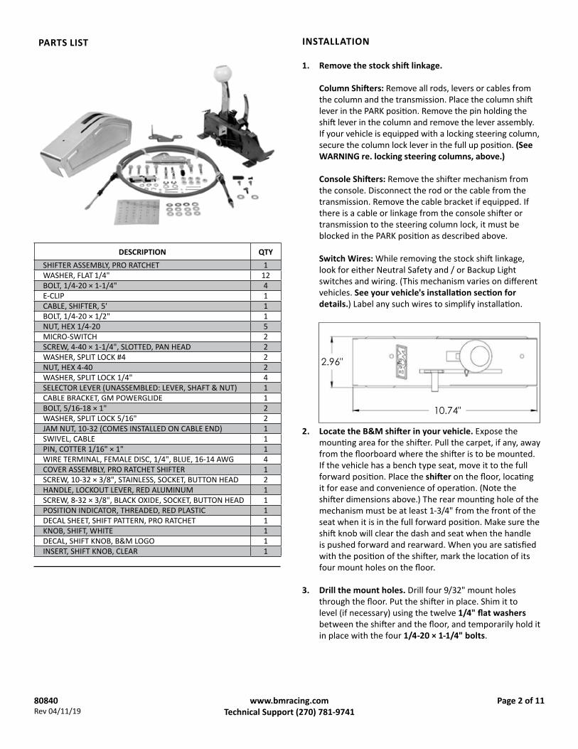
DESCRIPTION QTYSHIFTER ASSEMBLY, PRO RATCHET 1WASHER, FLAT 1/4" 12BOLT, 1/4-20 × 1-1/4" 4E-CLIP 1CABLE, SHIFTER, 5' 1BOLT, 1/4-20 × 1/2" 1NUT, HEX 1/4-20 5MICRO-SWITCH 2SCREW, 4-40 × 1-1/4", SLOTTED, PAN HEAD 2WASHER, SPLIT LOCK #4 2NUT, HEX 4-40 2WASHER, SPLIT LOCK 1/4" 4SELECTOR LEVER (UNASSEMBLED: LEVER, SHAFT & NUT) 1CABLE BRACKET, GM POWERGLIDE 1BOLT, 5/16-18 × 1" 2WASHER, SPLIT LOCK 5/16" 2JAM NUT, 10-32 (COMES INSTALLED ON CABLE END) 1SWIVEL, CABLE 1PIN, COTTER 1/16" × 1" 1WIRE TERMINAL, FEMALE DISC, 1/4", BLUE, 16-14 AWG 4COVER ASSEMBLY, PRO RATCHET SHIFTER 1SCREW, 10-32 × 3/8", STAINLESS, SOCKET, BUTTON HEAD 2HANDLE, LOCKOUT LEVER, RED ALUMINUM 1SCREW, 8-32 × 3/8", BLACK OXIDE, SOCKET, BUTTON HEAD 1POSITION INDICATOR, THREADED, RED PLASTIC 1DECAL SHEET, SHIFT PATTERN, PRO RATCHET 1KNOB, SHIFT, WHITE 1DECAL, SHIFT KNOB, B&M LOGO 1INSERT, SHIFT KNOB, CLEAR 1
PARTS LIST INSTALLATION
1. Remove the stock shift linkage.
Column Shifters: Remove all rods, levers or cables from the column and the transmission. Place the column shift lever in the PARK position. Remove the pin holding the shift lever in the column and remove the lever assembly. If your vehicle is equipped with a locking steering column, secure the column lock lever in the full up position. (See WARNING re. locking steering columns, above.)
Console Shifters: Remove the shifter mechanism from the console. Disconnect the rod or the cable from the transmission. Remove the cable bracket if equipped. If there is a cable or linkage from the console shifter or transmission to the steering column lock, it must be blocked in the PARK position as described above.
Switch Wires: While removing the stock shift linkage, look for either Neutral Safety and / or Backup Light switches and wiring. (This mechanism varies on different vehicles. See your vehicle's installation section for details.) Label any such wires to simplify installation.
2. Locate the B&M shifter in your vehicle. Expose the mounting area for the shifter. Pull the carpet, if any, away from the floorboard where the shifter is to be mounted. If the vehicle has a bench type seat, move it to the full forward position. Place the shifter on the floor, locating it for ease and convenience of operation. (Note the shifter dimensions above.) The rear mounting hole of the mechanism must be at least 1-3/4" from the front of the seat when it is in the full forward position. Make sure the shift knob will clear the dash and seat when the handle is pushed forward and rearward. When you are satisfied with the position of the shifter, mark the location of its four mount holes on the floor.
3. Drill the mount holes. Drill four 9/32" mount holes through the floor. Put the shifter in place. Shim it to level (if necessary) using the twelve 1/4" flat washers between the shifter and the floor, and temporarily hold it in place with the four 1/4-20 × 1-1/4" bolts.
2.96"
10.74"

80840Rev 04/11/19
Page 3 of 11www.bmracing.comTechnical Support (270) 781-9741
4. Drill the cable hole. Mark the location for the shifter cable hole 3" forward of the shifter’s front mount holes. Drill or cut a 1-1/2" hole through the floor.
NOTE: If your vehicle’s floor is too thin to properly support the shifter mechanism when bolted to it, fabricate a sheet metal stiffener to reinforce it.
5. Return the carpet to its original position (but do not secure it yet). Cut holes in the carpet for the shifter mount holes, and cut a 1-1/2" slit for the cable. (Do not use a drill bit to make the holes in the carpet.)
6. Assemble the cable and shifter. Secure the cable eye to the shifter pin with an E-clip. Then secure the cable’s mount tab to the outside surface of the shifter base with the 1/4-20 × 1/2" bolt and nut (apply medium strength thread-locking fluid to bolt). Align a bolt flat with the top edge of the cable mount tab on the shifter, as shown, for best fit of the shifter cover.
CAUTION: Do not kink the cable anywhere along its length, or it will lock up. The cable should be kept straight for at least 2" after it leaves the brass at each end.
WRONG
RIGHT
CABLE
SHIFTER
BRASS
FLOOR
7. Install the two switches on the shifter mechanism as shown, using the two #4-40 × 1-1/4" screws, lock washers and nuts.
CAUTION: Do not over-tighten the fasteners, as this may crack the switch housings.
After tightening the fasteners, check placement of the switches to verify that:• the Neutral Safety (bottom) switch closes in
NEUTRAL and PARK only; and• the Backup Light (top) switch closes in REVERSE only.
NOTES:• Refer to the shifter-transmission position table in
the “Operation” section.• The switch mount holes should allow the required
positioning for proper actuation. However, the switch arms may be carefully bent, if necessary.
8. Install the shifter in the vehicle. Slide the cable through the carpet and the hole in the floor, then bolt the shifter to the floor using the four 1/4-20 × 1-1/4" bolts, lock washers and nuts, and using the twelve 1/4" flat washers as leveling shims, if required. Do not bend the shifter mount tabs.
9. Route the cable approximately as shown. Avoid any sharp bends which may kink or otherwise damage the cable. Seal the cable hole shut to keep exhaust fumes, water, etc. out of the passenger compartment. Use clamps and / or cable ties (customer supplied) to secure
CABLE ROUTING
LARGE, WIDE LOOPSGIVE FREER SHIFTING &
LONGER CABLE LIFE LOOP CABLE BEHIND TAILSHAFT OR IN THIS APPROXIMATE AREA

80840Rev 04/11/19
Page 4 of 11www.bmracing.comTechnical Support (270) 781-9741
13. Remove the detent roller spring from the transmission.
10. Disconnect the throttle-to-transmission linkage, if any, and discard. The Powerglide selector lever supplied with this kit makes no provision for a throttle valve linkage.
11. Drain the transmission.
CAUTION: Be sure the transmission is cool before attempting to drain it.
Place a drain pan under the transmission. Remove the drain plug (if so equipped), or remove the pan bolts, one at a time, working back-to-front. As you loosen the last two bolts, carefully tilt the pan down and allow the fluid to drain.
NOTE: If your pan sticks to the gasket, carefully pry it free with a screwdriver (before loosening the last two bolts).
Remove the transmission pan and set it aside.
NOTE: The transmission in the following photos is situated upside-down on a work stand. 14. Remove the detent roller by removing its E-clip.
12. Remove the manual valve guide plate by removing the two bolts shown.
CAUTION: Heat will severely damage the shift cable, causing the housing to melt or become brittle. If the cable must be routed near exhaust system components, fabricate a heat shield. Do not wrap the cable, as this retains heat.
NOTE: The instruction photos show a transmis-sion on a work stand, not installed in a vehicle.
TRANSMISSION
PAN
CABLE
EXHAUSTPIPE
HEAT SHIELD(SHEET METAL)
MUFFLER CLAMP
U-BOLT
the cable housing in such a way as to prevent contact with the exhaust system, engine, or any moving parts.
80840Rev 04/11/19
Page 5 of 11www.bmracing.comTechnical Support (270) 781-9741
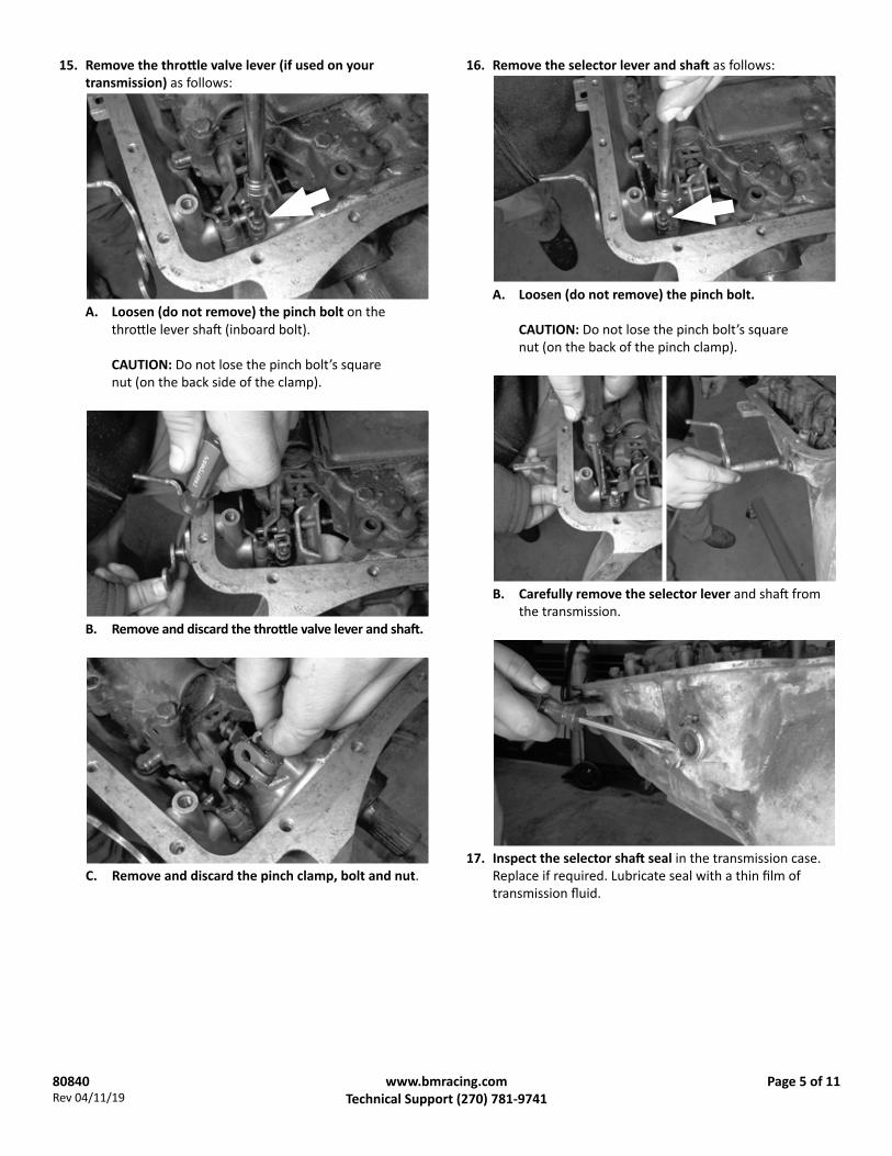
B. Remove and discard the throttle valve lever and shaft.
C. Remove and discard the pinch clamp, bolt and nut.17. Inspect the selector shaft seal in the transmission case.
Replace if required. Lubricate seal with a thin film of transmission fluid.
B. Carefully remove the selector lever and shaft from the transmission.
A. Loosen (do not remove) the pinch bolt on the throttle lever shaft (inboard bolt).
CAUTION: Do not lose the pinch bolt’s square nut (on the back side of the clamp).
15. Remove the throttle valve lever (if used on your transmission) as follows:
16. Remove the selector lever and shaft as follows:
A. Loosen (do not remove) the pinch bolt.
CAUTION: Do not lose the pinch bolt’s square nut (on the back of the pinch clamp).

80840Rev 04/11/19
Page 6 of 11www.bmracing.comTechnical Support (270) 781-9741
22. Reinstall the detent roller spring.
21. Reinstall the detent roller and its E-clip.
20. Align and assemble the internal and external selector levers: Hold the internal selector lever stationary, and rotate the selector shaft until its flat aligns with the serrations on the internal lever’s pinch clamp. Push the shaft firmly into the transmission until the internal lever stops against the shaft’s shoulder, then tighten the pinch bolt.
23. Engage the pin on the internal selector lever with the groove on the end of the manual valve.
18. Assemble the B&M selector lever (shaft, lever, and nut).
19. Install the assembled selector lever in the transmission with the lever pointing down, toward the bottom of the transmission. (If your vehicle’s configuration requires that the cable come from the front, install the selector lever pointing upwards. You will have to custom fabricate a cable bracket for this configuration.)

80840Rev 04/11/19
Page 7 of 11www.bmracing.comTechnical Support (270) 781-9741
24. Reinstall the manual valve guide plate while ensuring that the selector lever pin remains engaged in the manual valve groove. Tighten the two bolts to 15 lb-ft torque. Verify that the selector lever travels back and forth freely and smoothly, with a positive click in each selector position.
25. Scrape the old pan gasket off the pan and the transmission case, and clean the pan.
NOTE: If the transmission pan does not have a drain plug, you may wish to install a B&M Drain Plug Kit, or a deep, cast aluminum Powerglide transmission pan, at this time.
Reinstall the transmission pan with a new gasket. Reinstall (but do not tighten) the pan bolts at all locations, except the two rear holes on the left side.
26. Install the cable bracket at the two rear holes, using the two 5/16-18 × 1" bolts and lock washers. Tighten the pan bolts to 7-10 ft-lbs torque.
CAUTION: Do not over-tighten the pan bolts, as this can damage the pan gasket.
27. Attach the shifter cable to the cable bracket: First remove the small jam nut, two plastic dust boots, and one large nut and lock washer from the cable housing. Then insert the cable housing in the cable bracket, reinstall the lock washer and large nut on the cable (loosely, to allow room for adjustment), and reinstall the two dust boots.
28. Thread the swivel onto the cable to about the middle of the threaded section, then re-install (but do not tighten) the jam nut.
NOTE: This shifter is configured specifically for use with Powerglide transmissions. A limiter pin, installed through the shifter in the lower-forward hole (just below the switches), restricts shifter travel for the Powerglide’s two forward speeds.
80840Rev 04/11/19
Page 8 of 11www.bmracing.comTechnical Support (270) 781-9741
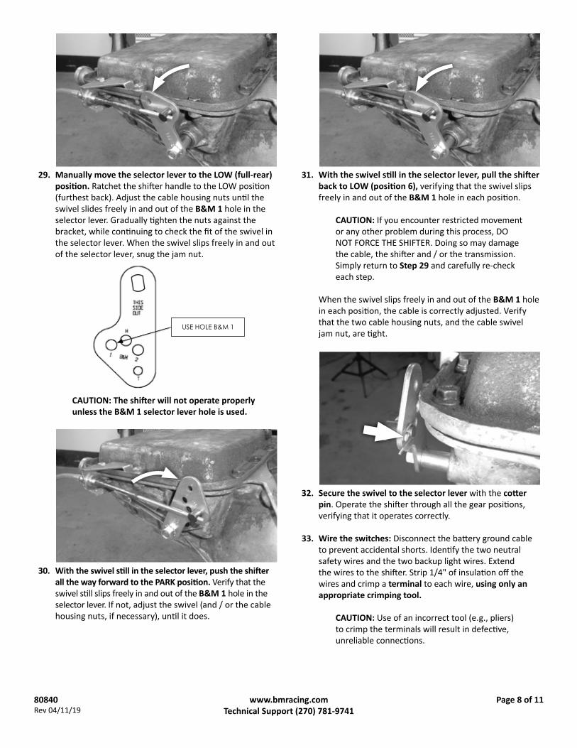
30. With the swivel still in the selector lever, push the shifter all the way forward to the PARK position. Verify that the swivel still slips freely in and out of the B&M 1 hole in the selector lever. If not, adjust the swivel (and / or the cable housing nuts, if necessary), until it does.
31. With the swivel still in the selector lever, pull the shifter back to LOW (position 6), verifying that the swivel slips freely in and out of the B&M 1 hole in each position.
CAUTION: If you encounter restricted movement or any other problem during this process, DO NOT FORCE THE SHIFTER. Doing so may damage the cable, the shifter and / or the transmission. Simply return to Step 29 and carefully re-check each step.
When the swivel slips freely in and out of the B&M 1 hole in each position, the cable is correctly adjusted. Verify that the two cable housing nuts, and the cable swivel jam nut, are tight.
32. Secure the swivel to the selector lever with the cotter pin. Operate the shifter through all the gear positions, verifying that it operates correctly.
33. Wire the switches: Disconnect the battery ground cable to prevent accidental shorts. Identify the two neutral safety wires and the two backup light wires. Extend the wires to the shifter. Strip 1/4" of insulation off the wires and crimp a terminal to each wire, using only an appropriate crimping tool.
CAUTION: Use of an incorrect tool (e.g., pliers)to crimp the terminals will result in defective, unreliable connections.
CAUTION: The shifter will not operate properly unless the B&M 1 selector lever hole is used.
USE HOLE B&M 1
29. Manually move the selector lever to the LOW (full-rear) position. Ratchet the shifter handle to the LOW position (furthest back). Adjust the cable housing nuts until the swivel slides freely in and out of the B&M 1 hole in the selector lever. Gradually tighten the nuts against the bracket, while continuing to check the fit of the swivel in the selector lever. When the swivel slips freely in and out of the selector lever, snug the jam nut.

80840Rev 04/11/19
Page 9 of 11www.bmracing.comTechnical Support (270) 781-9741
B. Verify the shifter mechanism is free of any debris and hardware. Lower the cover over the tips of the stick and the reverse lockout lever.
C. Push the stick forward and hold it there, lower the front of the cover over the front of the shifter, and continue to hold the stick forward.
D. Bring the cover over the rear of the shifter.
E. Release the stick, allowing it to return to its centered position. Then fasten the cover to the shifter with the two 10-32 screws.
A. Move the shifter into REVERSE (two pulls back from PARK / full-forward).
Tape or heat-shrink the terminal-wire connections for added protection of the crimps. Connect the neutral safety wires to the LOWER switch, and connect the backup light wires to the UPPER switch (see Step 7 illustration).
34. Verify switch function: Reconnect the battery ground cable, disconnect the coil wire and set the parking brake. Check the neutral safety switch by attempting to start the engine in each shifter position. The starter must crank only when the shifter is in either PARK or NEUTRAL. Check the backup light switch by verifying the backup light is on only when the shifter is in REVERSE. Adjust the switches if required. After verifying correct switch operation, reconnect the coil wire.
35. Install the shifter cover: Verify that there is a small square of insulating tape on the inside driver’s side of the shifter cover. (The tape prevents the switch terminals from touching the cover.) Then install the cover as follows:
36. Install the handle on the reverse lockout lever using the 8-32 button head screw. Install the handle on the left side of the lever for easy, one-hand operation. Screw the red shifter position indicator pointer through the slot into the indicator arm. Use a medium strength thread locker (such as Permatex blue) to prevent the pointer from backing out in use. Select the applicable shifter position indicator decal from the decal sheet, and install it to the left of the pointer.

80840Rev 04/11/19
Page 10 of 11www.bmracing.comTechnical Support (270) 781-9741
OPERATION
To move the transmission from one gear position to the next, pull or push the shifter handle to a full stop then release it (allowing it to return to its “centered” position). Repeat this action until the transmission is in the desired position—see the table below.
NOTE: The shifter-transmission positions shown apply to standard valve bodies. Custom valve bodies will alter your shifter-transmission positions accordingly.
37. Install the shifter knob: Apply medium strength thread locker to the shifter threads.
NOTE: If thread locker is not used, the knob may either loosen in use, or its threads may gall, making it impossible to remove the knob from the stick in the future.
Carefully thread the knob onto the stick.
CAUTION: Avoid cross-threading! The knob should spin onto the stick with no resistance. If you start to feel any resistance, STOP, remove the knob, and align the threads properly.
Tighten the knob onto the shifter. Align and install the B&M logo decal on top of the knob. Position the clear plastic knob insert over the knob, and push down on it sharply to snap it into place.
38. Fasten the carpet to the vehicle floor.
Congratulations! Your B&M Pro Ratchet® Shifter is now installed and ready to use.
CAUTION: Service the transmission according to manufacturer’s specifications before operating!
CAUTION: You must push the shifter forward TWICE (from positions 3 to position 1) in order to shift the transmission from REVERSE into PARK! DO NOT PARK THE VEHICLE IN SHIFTER POSITION 2, as the transmission’s park pawl will not be engaged, which may allow the vehicle to roll!
Shifting from NEUTRAL to REVERSE requires that the reverse lockout lever be pushed forward first. This feature is designed to prevent unintentional shifting from NEUTRAL into REVERSE while the vehicle is still moving forward.
Shifting to PARK: The Powerglide transmission’s selector lever travels twice the distance between PARK and REVERSE that it does between the remaining positions. Shifter position 1 (full-forward) is PARK; position 3 is REVERSE, and position 2 is a “transition” step between PARK and REVERSE.
SELECTOR LEVER PARK NONE REV NEUT DRIVE LOW
SHIFTERPOSITION
1 (FULL FWD) 2 3 4 5 6 (FULL
RWD)

80840Rev 04/11/19
Page 11 of 11www.bmracing.comTechnical Support (270) 781-9741
IMPORTANT: RETAIN THESE INSTRUCTIONS FOR FUTURE REFERENCE
B&M Performance & Off-Road maintains a highly-trained technical service department to answer your technical questions, provide additional product information and offer various recommendations.
B&M Technical Support: (270) 781-9741
□ Shifter moves freely into and out of all positions, as described in “Operation.”
CAUTION: If your shifter is not working properly do not attempt to drive your car! Verify you have followed all instructions. If the shifter is broken or defective return it to your B&M dealer.
INSTALLATION CHECKLIST
□ Locking steering column lever is permanently fastened in the full up position (Step 1).
□ Shifter is convenient to reach and has ample room for driver’s hand in both PARK and LOW (Step 2).
□ Carpet covers floorboard holes (Step 5).
□ Cable is e-clipped to the shifter pin, and cable housing is securely fastened to the shifter base (Step 6).
□ Shifter is securely mounted to floorboard (Step 8).
□ Cable is routed clear of exhaust system, engine, and any moving parts (Step 9).
□ Selector lever is securely fastened in transmission (Step 19).
□ Oil pan bolts are tightened to 7-10 lb-ft torque (Step 26).
□ Shifter is properly adjusted; cable boots are installed; cable nuts are tightened; swivel is secured with cotter key (Steps 29-32).
□ The Neutral safety switch is connected and properly adjusted to prevent engine start in forward and reverse drive gears (Step 34).
□ There is no debris in the shifter mechanism (Step 35 B).
□ Cover is installed (Step 35 E).