installation instructions for fc21 forward controls for … you are missing anything please email...
TRANSCRIPT
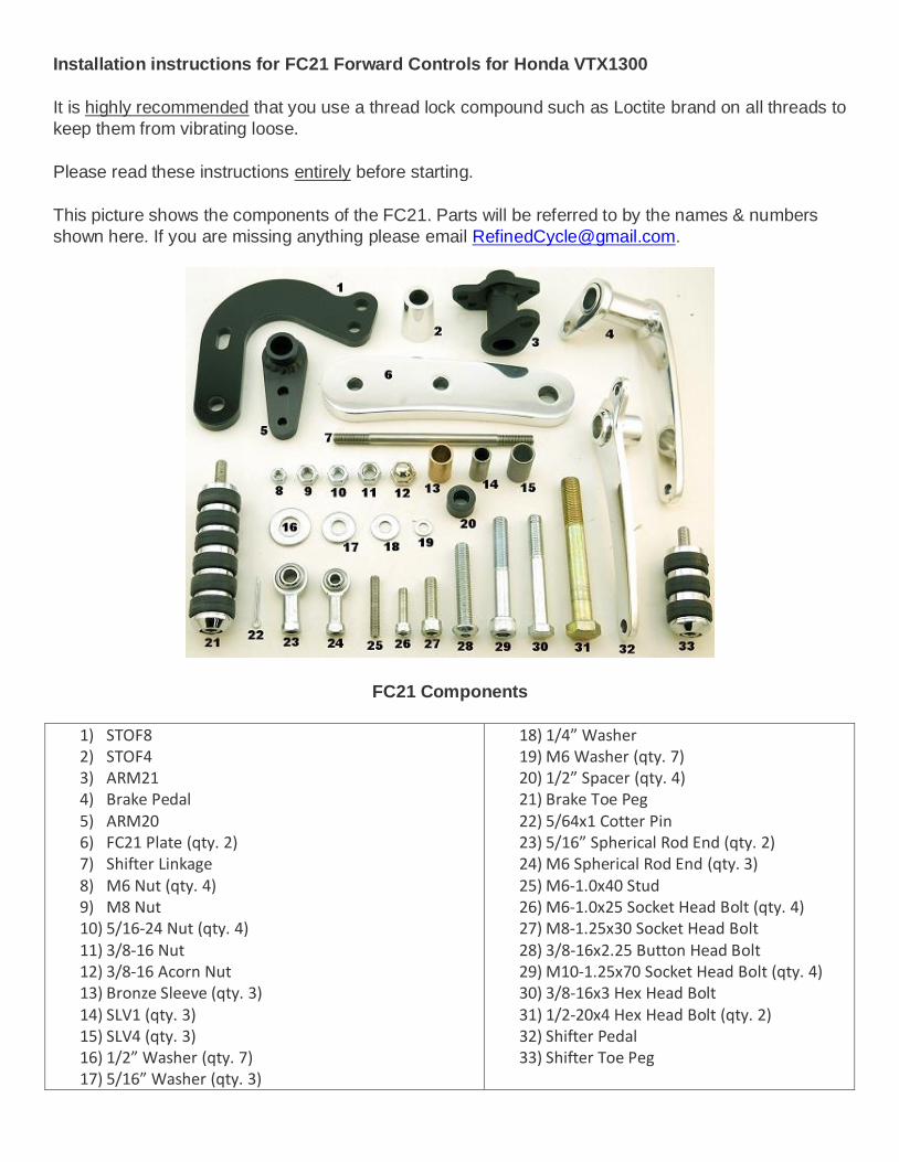
Installation instructions for FC21 Forward Controls for Honda VTX1300
It is highly recommended that you use a thread lock compound such as Loctite brand on all threads to
keep them from vibrating loose.
Please read these instructions entirely before starting.
This picture shows the components of the FC21. Parts will be referred to by the names & numbers
shown here. If you are missing anything please email [email protected].
FC21 Components
1) STOF8 2) STOF4 3) ARM21 4) Brake Pedal 5) ARM20 6) FC21 Plate (qty. 2) 7) Shifter Linkage 8) M6 Nut (qty. 4) 9) M8 Nut 10) 5/16-24 Nut (qty. 4) 11) 3/8-16 Nut 12) 3/8-16 Acorn Nut 13) Bronze Sleeve (qty. 3) 14) SLV1 (qty. 3) 15) SLV4 (qty. 3) 16) 1/2” Washer (qty. 7) 17) 5/16” Washer (qty. 3)
18) 1/4” Washer 19) M6 Washer (qty. 7) 20) 1/2” Spacer (qty. 4) 21) Brake Toe Peg 22) 5/64x1 Cotter Pin 23) 5/16” Spherical Rod End (qty. 2) 24) M6 Spherical Rod End (qty. 3) 25) M6-1.0x40 Stud 26) M6-1.0x25 Socket Head Bolt (qty. 4) 27) M8-1.25x30 Socket Head Bolt 28) 3/8-16x2.25 Button Head Bolt 29) M10-1.25x70 Socket Head Bolt (qty. 4) 30) 3/8-16x3 Hex Head Bolt 31) 1/2-20x4 Hex Head Bolt (qty. 2) 32) Shifter Pedal 33) Shifter Toe Peg

Brake Side…
Remove these 3 bolts.
Pull the whole assembly forward and away
from the exhaust so you can get to these two
bolts, then remove them. Note: There are
small spacers behind the brake master
cylinder that will fall out when you remove
the bolts. Don’t lose them, you will need
them later.
Remove this bolt.

Unhook just the bottom hook of the brake
switch spring.
Using needle nose pliers, remove the bottom
hook and then the top hook of the brake
return spring.
Turn the brake pedal so that you can get to
this cotter pin. Cut and remove it.

Remove this clevis pin to remove the brake
pedal.
Drill this hole a little bigger using a 3/8” drill
bit.
Place the 3/8x3 Hex Head Bolt into the hole
from the back.

Apply some axle grease to all of the SLV1,
SLV4, Bronze Sleeves, ARM20 and ARM21.
Insert 2 of the Bronze Sleeves into the
ARM21and the other one into the ARM20.
Now, insert 2 of the SLV1 into the
ARM21and the other one into the ARM20.

Place the ARM21onto the 3/8x3 Hex Head
Bolt as shown. Clean any excess grease off
of the bolt.
Line up the top of the two holes in the
ARM21 with the master cylinder clevis and
push in the clevis pin.
Insert the supplied 5/64x1 Cotter Pin into the
clevis pin and separate and bend the ends
around to secure.

Place the top hook of the brake return spring
into the bottom hole of the ARM21 then
reattach the bottom hook where it was
originally.
Place the bottom hook of the brake switch
spring into this hole of the ARM21.
Hold the entire assembly flat in your hand to
make it easier to replace the spacers
between the master cylinder and it’s mount
and line up the holes.

Replace the heat shield and secure with the
bolts removed earlier.
Secure the ARM21 with a 5/16” Washer and
a 3/8-16 Acorn Nut.
The brake light switch will need to be
adjusted. Do this by turning the adjustment
wheel. Hold the brake light switch in one
hand to keep it from turning while turning the
wheel. If the spring tension is too tight, your
brake light will be on all of the time. If it is too
loose, it will not come on when the brake is
applied. To test, turn your key on and
observe your brake light while rotating and
releasing the ARM21 a few times. If the
brake light works as desired, no adjustment
is necessary. If it stays on, turn the
adjustment wheel to loosen the spring
tension on the brake light switch and retry. If
it does not come on at all, tighten the tension
on the brake light switch. With a little trial and
error you will find the right position.

Place a 1/2" Washer onto BOTH of the 1/2-
20x4 Hex Head Bolts.
NOTE: If you will be using a foot peg that
connects with a clevis like these shown
below, add AN ADDITIONAL 1/2" Washer
now, otherwise the bolt will be too long for
the clevis when you install it later.
Insert two M10-1.25x70 Socket Head Bolts
and a 1/2-20x4 Hex Head Bolt into an FC21
Plate as shown.
Note: Installing as shown will give you about
6” forward movement from stock position.
The FC21 Plate can be installed flipped
upside down if you would like the controls
about 1/2" farther forward. All linkages will
have to be adjusted accordingly to
accommodate the difference in pedal
location.
Place a 1/2" Spacer onto both of the M10-
1.25x70 Socket Head Bolts.

Secure the FC21 Plate through the brake
master cylinder mount and to the frame.
Place another 1/2" Washer onto the 1/2-20x4
Hex Head Bolt.
The inside of the Brake Pedal will likely have
some polishing compound residue. Use a
cloth or paper towel and make sure the
inside is ABSOLUTELY clean. This will
affect how well your Brake Pedal will rotate.
After cleaning, put a little grease in there.

Place two SLV4’s into the Brake Pedal.
Slide the Brake Pedal onto the 1/2-20x4 Hex
Head Bolt.
Place another 1/2" Washer onto the 1/2-20x4
Hex Head Bolt.
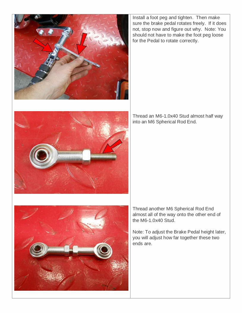
Install a foot peg and tighten. Then make
sure the brake pedal rotates freely. If it does
not, stop now and figure out why. Note: You
should not have to make the foot peg loose
for the Pedal to rotate correctly.
Thread an M6-1.0x40 Stud almost half way
into an M6 Spherical Rod End.
Thread another M6 Spherical Rod End
almost all of the way onto the other end of
the M6-1.0x40 Stud.
Note: To adjust the Brake Pedal height later,
you will adjust how far together these two
ends are.

Insert an M6-1.0x25 Socket Head Bolt into
one of the M6 Spherical Rod Ends.
Place an M6 Washer on.
Now insert it into the ARM21, place another
M6 Washer on and secure with an M6 Nut.
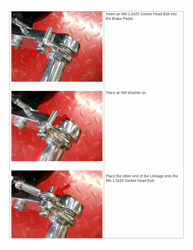
Insert an M6-1.0x25 Socket Head Bolt into
the Brake Pedal.
Place an M6 Washer on.
Place the other end of the Linkage onto the
M6-1.0x25 Socket Head Bolt.

Place another M6 Washer on.
Thread an M6 Nut on and just tighten
enough to snug it at this point. Do not use
threadlock here yet. (You ARE using
threadlock right?)
Install the Brake Toe Peg and secure with a
5/16-24 Nut.
At this time you should sit on the bike (if it is
secure) and test that the Brake Pedal height
is at your desired angle. If not, remove the
M6 Nut and Washer that you only snugged
and thread the M6 Spherical Rod End farther
on or off of the M6-1.0x40 Stud as
applicable. When all adjustment is made,
threadlock and tighten the connection.
This completes the Brake Side.

Shifter Side…
Lower the kickstand, remove these 5 bolts
and pull off the chrome cover.
Loosen this nut and thread it the rest of the
way onto the linkage rod. (It is a LEFT HAND
thread.)
Observe the small dot on the end of the
splined shaft and make sure it is lined up
with the split in the shifter arm. IF it is not,
remove the clamping bolt, slide the shifter
arm off the splined shaft, rotate the shifter
arm to line it up, then replace and tighten the
clamping bolt.
Note: If you decide to flip the controls over
for the 6.5” position, you MAY find that the
shifter arm needs to be rotated one tooth
counter-clockwise for optimal Shifter Pedal
position, but you may not need to move it at
all.

Loosen this nut and thread it the rest of the
way onto the linkage rod. Twist the shifter
linkage to thread it out to remove it.
Remove these 2 bolts to remove the left side
control.
Thread the original shifter linkage back into
the shifter arm on the spline where you
removed it from. (Left Hand End). Now
Thread an M6 Spherical Rod End onto the
other end as shown.

Insert two M10-1.25x70 Socket Head Bolts
and a 1/2-20x4 Hex Head Bolt into an FC21
Plate as shown.
NOTE: Don’t forget to add an additional 1/2"
Washer before inserting the 1/2-20x4 Hex
Head Bolt if you will be using a clevis for your
foot peg
Place the STOF8 onto the two M10-1.25x70
Socket Head Bolts.
Slide 1/2" Spacers onto the two M10-1.25x70
Socket Head Bolts.

Secure the assembly to the frame and slide a
STOF4 on as shown.
Clean the Shifter Pedal as you did with the
brake side and grease.
Insert an SLV4.

Place the Shifter Pedal onto the bolt.
Place a 1/2” Washer on.
Install a foot peg and tighten. Then make
sure the Shifter Pedal rotates freely. If it
does not, stop now and correct.

Insert a 3/8-16x2.25 Button Head Bolt into
the ARM20 that you previously installed the
sleeves into.
Place a 5/16” Washer onto the bolt.
Connect to the top hole of the STOF8, clean
any excess grease off of the bolt and secure
with a 5/16” Washer and a 3/8-16 Nut.

Install the Shifter Toe Peg and secure with a
5/16-24 Nut.
Thread 5/16-24 Nuts about half way onto
both ends of the supplied Shifter Linkage.
Then thread on 5/16” Spherical Rod Ends.

Insert an M6-1.0x25 Socket Head Bolt into
the Shifter Pedal.
Place TWO M6 Washers onto the bolt.
Place one end of the Shifter Linkage onto the
bolt and secure with an M6 Nut.

Insert an M8-1.25x30 Socket Head Bolt into
the other end of the linkage then slide a 1/4"
Washer onto the bolt.
Connect to the middle hole of the ARM20
and secure with an M8 Nut.
Insert an M6-1.0x25 Socket Head Bolt into
the bottom hole of the ARM20 then slide an
M6 Washer onto the bolt.

Pull the M6-1.0x25 Socket Head Bolt back
out just enough to give you room to place the
end of the original linkage onto the bolt and
secure with an M6 Nut. Note: Make sure the
M6 Washer does not fall off when you are
doing this.
Adjust the Shifter Pedal height with the
original linkage. Make sure there is enough
thread in both ends for a secure connection.
If you need more adjustment, you can
remove the front linkage from the Pedal and
adjust it as well, then reconnect. After the
height is adjusted to the desired position,
tighten the nuts against ALL of the Spherical
Rod Ends.
Replace the chrome cover and secure.
That’s it! It is recommended that at this point
you double check that ALL connections are
tight and take the bike for a test ride and
make any other adjustments necessary for
the optimal position of your shifter and brake
pedals.
Enjoy the ride!