the brake assist system - · pdf filefor all inspection, adjustment and repair instructions....
TRANSCRIPT

The Brake Assist System
Design and function
Self-study programme 264
Service.
2
New WarningNote
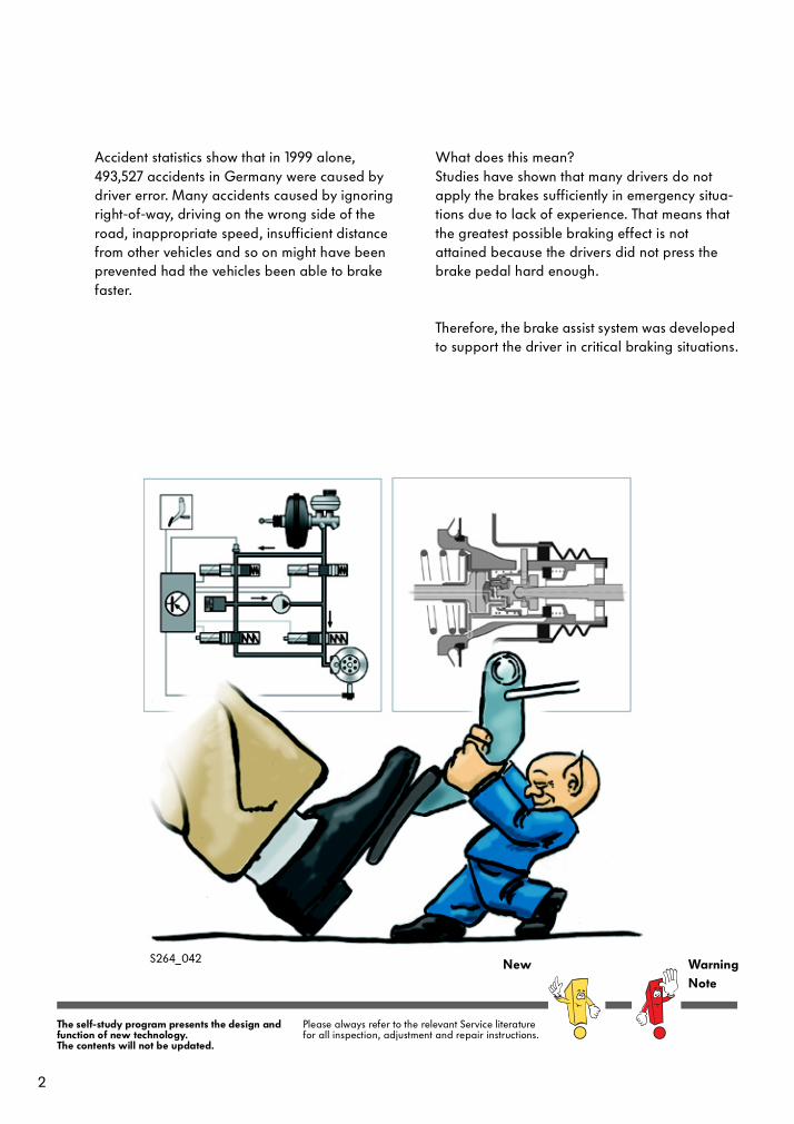
Accident statistics show that in 1999 alone, 493,527 accidents in Germany were caused by driver error. Many accidents caused by ignoring right-of-way, driving on the wrong side of the road, inappropriate speed, insufficient distance from other vehicles and so on might have been prevented had the vehicles been able to brake faster.
What does this mean?Studies have shown that many drivers do not apply the brakes sufficiently in emergency situa-tions due to lack of experience. That means that the greatest possible braking effect is not attained because the drivers did not press the brake pedal hard enough.
Therefore, the brake assist system was developed to support the driver in critical braking situations.
The self-study program presents the design and function of new technology.The contents will not be updated.
Please always refer to the relevant Service literature for all inspection, adjustment and repair instructions.
S264_042
3
Introduction . . . . . . . . . . . . . . . . . . . . . . . . . . . . . . . . . . .4
The hydraulic brake assist system . . . . . . . . . . . . . . . . 8
Design, comparison and function . . . . . . . . . . . . . . . . . 8
Electrical components . . . . . . . . . . . . . . . . . . . . . . . . . . 14
Functional diagram . . . . . . . . . . . . . . . . . . . . . . . . . . . . 19
The mechanical brake assist system . . . . . . . . . . . . . 20
Design and function . . . . . . . . . . . . . . . . . . . . . . . . . . . 20
Service . . . . . . . . . . . . . . . . . . . . . . . . . . . . . . . . . . . . . 27
Test your knowledge . . . . . . . . . . . . . . . . . . . . . . . . . . .28
Table of contents

4
Early in
automobile development, the brakes played a rather subordinate role because the friction in the drive train was so great that a vehicle was slowed sufficiently even without the brakes being used.
Increasing power and speed as well as con-stantly increasing traffic density led to the consid-eration in the 20s of how an appropriate brake system could provide a counterbalance to greater power and driving performance.
But only after advances in electronics and micro-electronics could systems be developed which could react fast enough in emergency situations.
The ancestor of the electronic brake systems is the ABS, which, since its introduction in 1978, has been continuously further developed and extended by additional functions. These functions intervene actively in the driving process to increase driving stability.
Currently, the trend in development is to driver support systems such as the brake assist system.The brake assist system supports the driver when braking in emergency situations to achieve the shortest possible brake path while maintaining steering ability.
Introduction
Activewheelspin controlsystems
Mechanicalbrakes
Driver supportsystems
Brake assist system and future sys-
tems
ABS TCSEDL
EBDEBCESP
S264_009
5
What does the brake assist
system do?
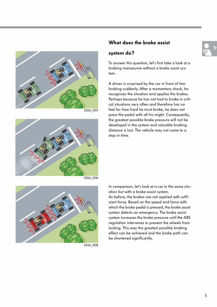
To answer this question, let’s first take a look at a braking manoeuvre without a brake assist sys-tem.
A driver is surprised by the car in front of him braking suddenly. After a momentary shock, he recognises the situation and applies the brakes. Perhaps because he has not had to brake in criti-cal situations very often and therefore has no feel for how hard he must brake, he does not press the pedal with all his might. Consequently, the greatest possible brake pressure will not be developed in the system and valuable braking distance is lost. The vehicle may not come to a stop in time.
In comparison, let’s look at a car in the same situ-ation but with a brake assist system.As before, the brakes are not applied with suffi-cient force. Based on the speed and force with which the brake pedal is pressed, the brake assist system detects an emergency. The brake assist system increases the brake pressure until the ABS regulation intervenes to prevent the wheels from locking. This way the greatest possible braking effect can be achieved and the brake path can be shortened significantly.
S264_008
S264_006
S264_005

6
Depending on the manufacturer of the wheelspin regulation system, the developmental goal of a brake assist system was attained in different ways. Currently, we can distinguish between two different types:
- the hydraulic brake assist systems and- the mechanical brake assist systems.
In hydraulic brake assist systems, like that from Bosch, the return flow pump of the ABS/ESP hydraulic system provides pressure, thus the expression „hydraulic brake assist system“. In this context, we speak of active pressure develop-ment.The advantage in design is that no additional components needed to be integrated.
At VOLKSWAGEN, the hydraulic brake assist system is currently being used in the 2002 Polo, the 2001 Passat and the D-class vehicle.
Introduction
S264_075 S264_076

7
In the mechanical brake assist systems from Con-tinental-Teves, brake pressure is developed and an emergency situation is detected by mechani-cal components in the brake servo.
The mechanical brake assist system is being used in the current models of the Golf and Bora.
Both systems make use of existing system compo-nents to implement the function of the brake assist system. Therefore brake assist systems are currently available only in conjunction with ESP.
In this self-study programme, the differences in design and function between the hydraulic and mechanical brake assist systems will be described.
S264_078S264_077

8
Design...
The central component in the Bosch brake assist system is the hydraulic unit with the integrated ABS control unit and the return flow pump. The brake pressure sender in the hydraulic unit, the speed sensors and the brake light switch supply signals to the brake assist system so that it can identify an emergency.Pressure is raised in the brake slave cylinders by the actuation of certain valves in the hydraulic unit and the return flow pump for TCS/ESP.
The hydraulic brake assist system
a - Brake servo
b - Brake pressure sensor
c - Brake light switch
d - Hydraulic unit
e - Return flow pump
f - Control unit
g - Brake slave cylinder
h - Speed sensor
ac
g
d
h
f
e
b
... Comparison...
The vehicle without a brake assist system attains the ABS regulation range later than the vehicle with a brake assist system and consequently has a longer brake path.
ABS regulation range
Bra
ke p
ress
ure
(p)
in b
ar
Time (t) in s
Vehicle with brake assist systemVehicle without brake assist system
S264_011
S264_001

9
... and Function
The function of the brake assist systems can be divided into two phases:
- Phase 1 - Start of brake assist system intervention
- Phase 2 - Conclusion of brake assist system intervention
If the trigger conditions have been fulfilled, the brake assistance increases the brake pressure. The ABS regulation range is quickly attained through this active pressure increase.
The electronic stability program switch valve N225 in the hydraulic unit is opened and the electronic stability program high-pressure valve N227 is closed. Consequently, the pressure cre-ated by the actuation of the return flow pump is directed immediately to the brake slave cylin-ders.
Brake pressure, brake assist systemPedal pressure of driver
Phase 1 Phase 2
cb
d
a = Accumulator
b = ESP (brake pressure) switch valve N225c = ESP high-pressure valve N227d = Return pressure valve
Brake slave cylinder
The brake assist system increases brake
pressure until ABS regulation intervenes.
p (bar)
t (s)
a
S264_012
S264_016

10
The function of the brake assist system is to increase the brake pressure as quickly as possi-ble to the maximum value. The ABS function, which is supposed to prevent the wheels from locking, limits the pressure increase when the locking threshold is reached. That means that once the ABS intervention has begun, the brake assist system can not further increase the brake pressure.
When the ABS intervenes, the ESP (brake pres-sure) switch valve N225 is closed again and the ESP high-pressure valve N227 is opened. The discharge from the return flow pump keeps the brake pressure below the locking threshold.
The hydraulic brake assist system
cb
d
Brake pressure at brake slave cylinderPedal pressure of driver
p (bar)
t (s)
Phase 1
ABS intervention
a = Accumulatorb = ESP (brake pressure) switch valve N225c = ESP high-pressure valve N227
d = Return flow pump
a
Phase 1
S264_013
S264_017

11
If the driver reduces the pressure on the brake pedal, the trigger conditions are no longer ful-filled. The brake assist system concludes that the emergency situation has been resolved and moves to phase 2. Now the pressure in the brake slave cylinders is adapted to the driver’s pressure on the brake pedal. The transition from phase 1 to phase 2 occurs not with a jump but smoothly, with the brake assist system reducing its contribu-tion to the pressure relative to the reduction of pressure on the brake pedal. When its contribu-tion finally reaches zero, normal braking function is restored.
The brake assist system also ends its intervention when the vehicle speed drops below a prede-fined value. In both cases, brake pressure is reduced by the actuation of the corresponding valves. Brake fluid can flow to the accumulator and is pumped back into the brake fluid reservoir by the return flow pump.
The brake pressure is reduced.
Brake pressure at brake slave cylinderPedal pressure of driver
p (bar)
t (s)
Phase 2
a
Brake fluid reservoir
Phase 2
S264_018
S264_014
a = Accumulatorb = ESP (brake pressure) switch valve N225c = ESP high-pressure valve N227d = Return flow pump
12
The trigger conditions
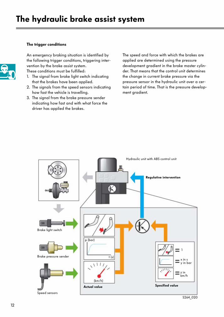
An emergency braking situation is identified by the following trigger conditions, triggering inter-vention by the brake assist system.These conditions must be fulfilled:1. The signal from brake light switch indicating
that the brakes have been applied.2. The signals from the speed sensors indicating
how fast the vehicle is travelling.3. The signal from the brake pressure sender
indicating how fast and with what force the driver has applied the brakes.
The speed and force with which the brakes are applied are determined using the pressure development gradient in the brake master cylin-der. That means that the control unit determines the change in current brake pressure via the pressure sensor in the hydraulic unit over a cer-tain period of time. That is the pressure develop-ment gradient.
The hydraulic brake assist system
p (bar)
Brake light switch
Brake pressure sender t (s)
(km/h)
x in sy in bar
1
z in km/h
Speed sensors
Actual value Specified value
Hydraulic unit with ABS control unit
Regulative intervention
S264_020

13
The intervention threshold for the brake assist system is a predefined value depending on the vehicle speed. If the brake pedal pressure exceeds this defined value in a period of time, the brake assist system initiates intervention. When the change in pressure drops below this threshold, the brake assist system ends its inter-vention.
In other words, if the pedal pressure reaches a certain value within a short period t1, the inter-vention conditions are fulfilled and the brake assist system intervenes. If the same pedal pres-sure is attained only after a longer time t2, the curve is flat and the brake assist system does not intervene. Thus, no intervention occurs if:
- the brake pedal is pressed to slowly or not at all,
- the change in pressure remains below the threshold,
- the vehicle speed is to low or- the driver has applied the brakes with suffi-
cient force.
An experienced driver develops sufficient pressure using the
brake pedal and the brake servo. ABS prevents the wheels
from locking.
The slope of the pressure curve is the determining factor for brake assist system intervention
p (bar)
p (bar)
t (s)
t (s)
t1 t2
Brake pressure with ABS intervention
Pedal pressure of driver
S264_010
S264_021

14
Electrical components
Brake light switch F
The brake light switch is installed in the pedal cluster and detects the operation of the brake pedal.
● How it worksThe brake light switch is a classic mechanical two-position push button.
● How the signal is usedThe switch provides one of two signals:brake pedal pressed orbrake pedal not pressed.
The signal from the brake light switch is used for the various brake systems, the engine manage-ment system and the switching on of the brake lights.
● Switch failureThe brake assist system is not functional without the brake light switch signal.
● Self-diagnosisA switch defect will be detected by self-diagnosis and saved in the fault memory. If the switch is renewed, it must be adjusted according to the workshop manual.
The hydraulic brake assist system
Signal:
not
pressed
Signal:
pressed
S264_029
S264_028
S264_025
15
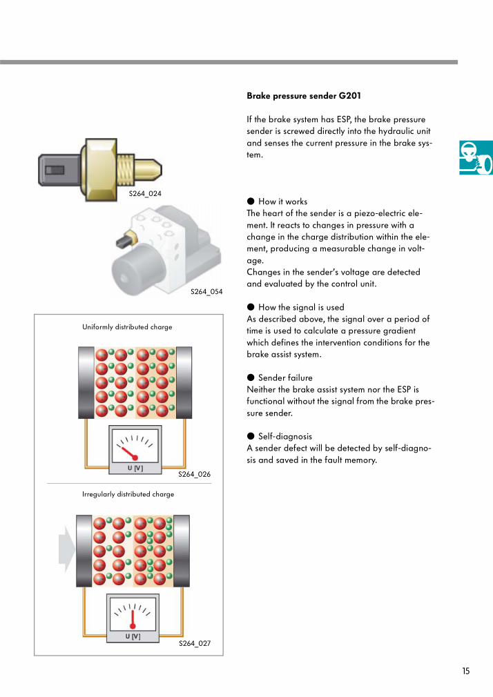
Brake pressure sender G201
If the brake system has ESP, the brake pressure sender is screwed directly into the hydraulic unit and senses the current pressure in the brake sys-tem.
● How it worksThe heart of the sender is a piezo-electric ele-ment. It reacts to changes in pressure with a change in the charge distribution within the ele-ment, producing a measurable change in volt-age.Changes in the sender’s voltage are detected and evaluated by the control unit.
● How the signal is usedAs described above, the signal over a period of time is used to calculate a pressure gradient which defines the intervention conditions for the brake assist system.
● Sender failureNeither the brake assist system nor the ESP is functional without the signal from the brake pres-sure sender.
● Self-diagnosisA sender defect will be detected by self-diagno-sis and saved in the fault memory.
Uniformly distributed charge
Irregularly distributed charge
S264_027
S264_026
S264_054
S264_024

16
Speed sensors G44 - G47
The speed sensors are inductive sensors which, using a rotor on each wheel hub as sender wheel, determine the current rotational speed of the wheels.
● How it worksThe sensor consists of a soft iron core with a per-manent magnet and a coil.The magnetic field which the permanent magnet creates over the iron core is influenced by the sender wheel. Changes in the magnetic field induce measurable voltage in the sensor coil. The faster the sender wheel passes the coil, the higher the frequency of the voltage change.
● How the signal is usedThe ABS control unit calculates the rotational speed of each wheel based on the frequency.The rotational speed of the wheels is used by a variety of different vehicle systems.
● Sensor failureWithout the speed sensor signal, the brake assist system cannot calculate the speed-dependent threshold. The brake assist system is switched off.
● Self-diagnosisA defect in a speed sensor is detected by self-diagnosis and saved in the fault memory.
The hydraulic brake assist system
a - Permanent magnet
b - Soft iron core
c - Coil
d - Rotor
a
b
c
d
U (V)
S264_022
S264_023
17
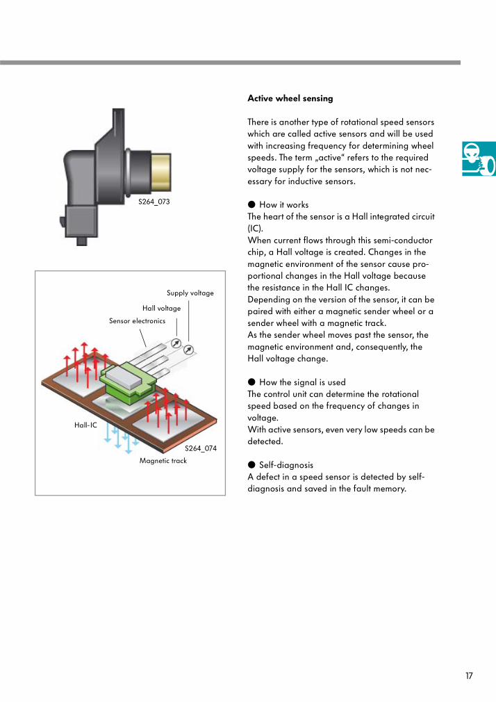
Active wheel sensing
There is another type of rotational speed sensors which are called active sensors and will be used with increasing frequency for determining wheel speeds. The term „active“ refers to the required voltage supply for the sensors, which is not nec-essary for inductive sensors.
● How it worksThe heart of the sensor is a Hall integrated circuit (IC).When current flows through this semi-conductor chip, a Hall voltage is created. Changes in the magnetic environment of the sensor cause pro-portional changes in the Hall voltage because the resistance in the Hall IC changes.Depending on the version of the sensor, it can be paired with either a magnetic sender wheel or a sender wheel with a magnetic track.As the sender wheel moves past the sensor, the magnetic environment and, consequently, the Hall voltage change.
● How the signal is usedThe control unit can determine the rotational speed based on the frequency of changes in voltage. With active sensors, even very low speeds can be detected.
● Self-diagnosisA defect in a speed sensor is detected by self-diagnosis and saved in the fault memory.
Supply voltage
Hall voltage
Hall-IC
Magnetic track
Sensor electronics
S264_074
S264_073
18
The hydraulic brake assist system
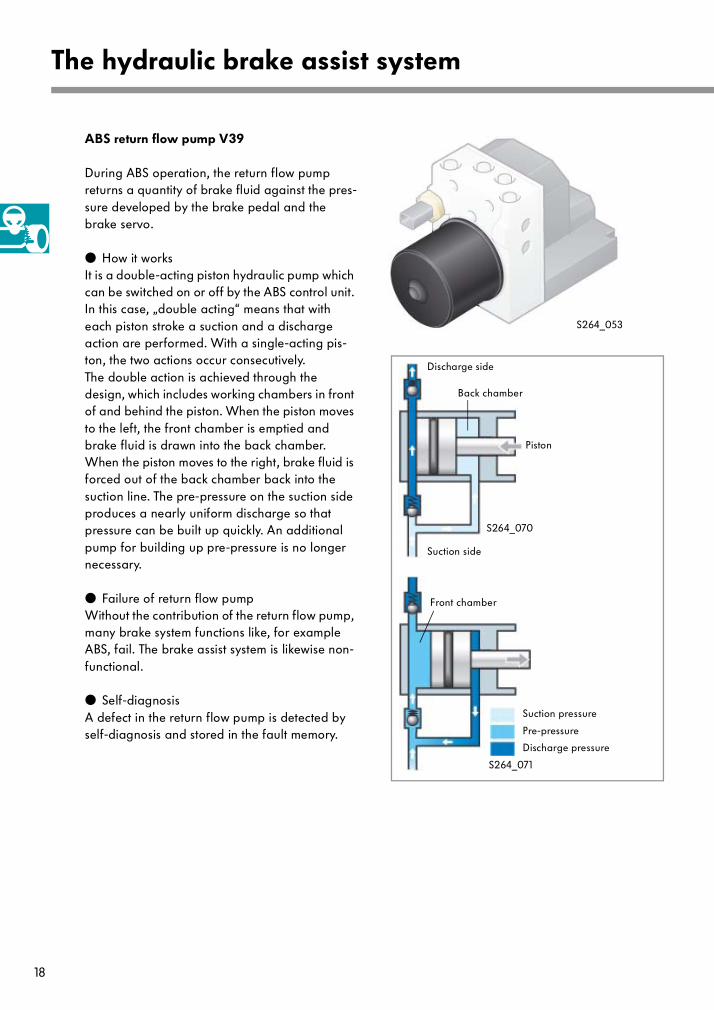
ABS return flow pump V39
During ABS operation, the return flow pump returns a quantity of brake fluid against the pres-sure developed by the brake pedal and the brake servo.
● How it worksIt is a double-acting piston hydraulic pump which can be switched on or off by the ABS control unit. In this case, „double acting“ means that with each piston stroke a suction and a discharge action are performed. With a single-acting pis-ton, the two actions occur consecutively.The double action is achieved through the design, which includes working chambers in front of and behind the piston. When the piston moves to the left, the front chamber is emptied and brake fluid is drawn into the back chamber. When the piston moves to the right, brake fluid is forced out of the back chamber back into the suction line. The pre-pressure on the suction side produces a nearly uniform discharge so that pressure can be built up quickly. An additional pump for building up pre-pressure is no longer necessary.
● Failure of return flow pumpWithout the contribution of the return flow pump, many brake system functions like, for example ABS, fail. The brake assist system is likewise non-functional.
● Self-diagnosisA defect in the return flow pump is detected by self-diagnosis and stored in the fault memory.
Discharge side
Suction side
Back chamber
Front chamber
Piston
Suction pressure
Pre-pressure
Discharge pressure
S264_071
S264_070
S264_053
19
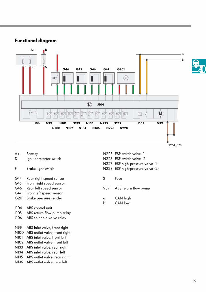
Functional diagram
A+ BatteryD Ignition/starter switch
F Brake light switch
G44 Rear right speed sensorG45 Front right speed sensorG46 Rear left speed sensorG47 Front left speed sensorG201 Brake pressure sender
J104 ABS control unitJ105 ABS return flow pump relayJ106 ABS solenoid valve relay
N99 ABS inlet valve, front rightN100 ABS outlet valve, front rightN101 ABS inlet valve, front leftN102 ABS outlet valve, front leftN133 ABS inlet valve, rear rightN134 ABS inlet valve, rear leftN135 ABS outlet valve, rear rightN136 ABS outlet valve, rear left
N225 ESP switch valve -1-N226 ESP switch valve -2-N227 ESP high-pressure valve -1- N228 ESP high-pressure valve -2-
S Fuse
V39 ABS return flow pump
a CAN highb CAN low
A+
G44
F
D
G45 G46 G47 G201
a
b
J106 N99
N100
N101
N102
N133
N134
N135
N136
N225
N226
N227
N228
J105 V39
S S S
S264_078
J104

20
Design ...
The heart of the Continental-TEVES mechanical brake assist system is a mechanical switch com-ponent in the brake servo.
The mechanical brake assist system
Mechanical switch componentin brake servo
S264_030
21
Locking sleeve with spring
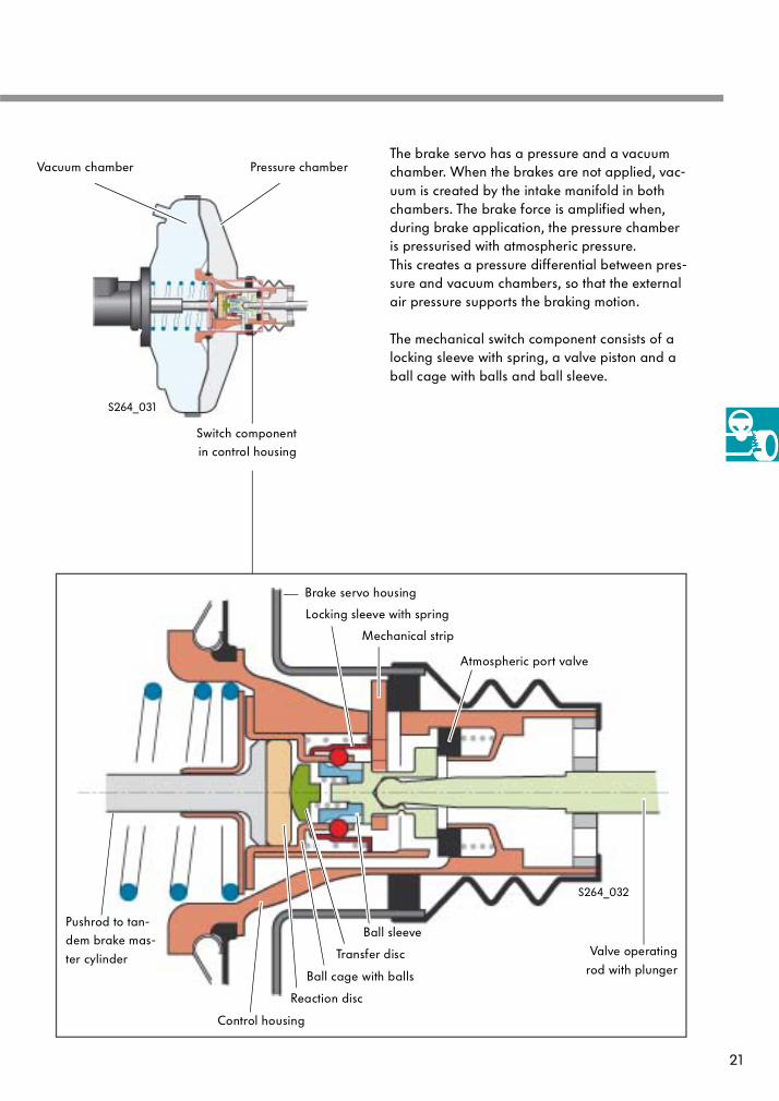
The brake servo has a pressure and a vacuum chamber. When the brakes are not applied, vac-uum is created by the intake manifold in both chambers. The brake force is amplified when, during brake application, the pressure chamber is pressurised with atmospheric pressure.This creates a pressure differential between pres-sure and vacuum chambers, so that the external air pressure supports the braking motion.
The mechanical switch component consists of a locking sleeve with spring, a valve piston and a ball cage with balls and ball sleeve.
Ball cage with balls
Ball sleeve
Valve operating
rod with plunger
Vacuum chamber Pressure chamber
Switch componentin control housing
Reaction disc
Brake servo housing
Pushrod to tan-dem brake mas-
ter cylinder
Control housing
Mechanical strip
Transfer disc
S264_032
S264_031
Atmospheric port valve
22
The mechanical brake assist system
... and Function
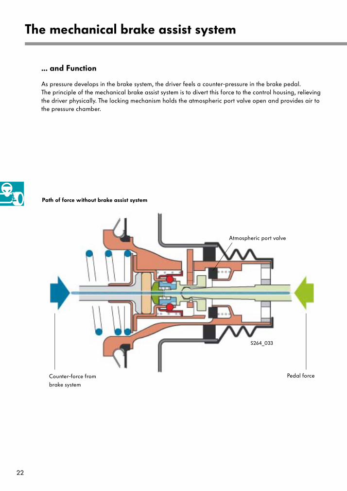
As pressure develops in the brake system, the driver feels a counter-pressure in the brake pedal.The principle of the mechanical brake assist system is to divert this force to the control housing, relieving the driver physically. The locking mechanism holds the atmospheric port valve open and provides air to the pressure chamber.
Pedal forceCounter-force from
brake system
Path of force without brake assist system
S264_033
Atmospheric port valve
23
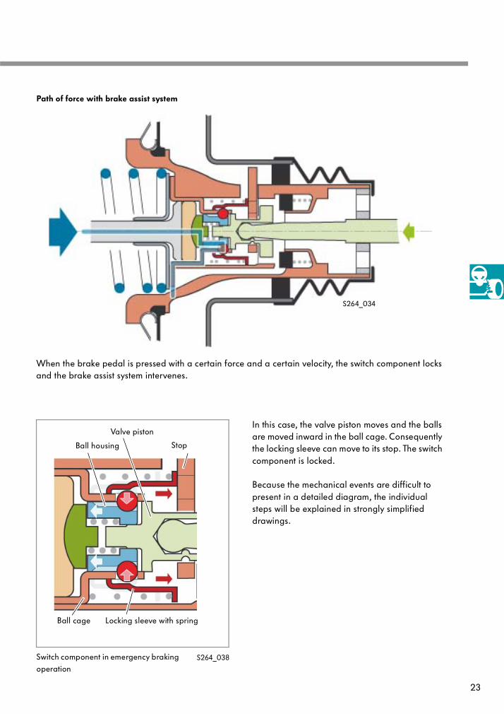
When the brake pedal is pressed with a certain force and a certain velocity, the switch component locks and the brake assist system intervenes.
In this case, the valve piston moves and the balls are moved inward in the ball cage. Consequently the locking sleeve can move to its stop. The switch component is locked.
Because the mechanical events are difficult to present in a detailed diagram, the individual steps will be explained in strongly simplified drawings.
Locking sleeve with springBall cage
Ball housing
Switch component in emergency braking operation
Valve piston
Stop
S264_038
Path of force with brake assist system
S264_034

24
The mechanical brake assist system
Assembly group
Parts Colour
a Valve operating rod, valve piston, ball housing, transfer disc
b Locking sleeve, mechanical stop
c Ball cage, balls,control housing
If the brake is applied too slowly, the brake assist function is not triggered. That means that the driver feels the full counter-pressure from the brake system through the brake pedal as coun-ter-force which he must overcome in order to brake more heavily.
If the brake pedal is pressed very fast, the brake assist function is triggered.The major portion of the counter-force is diverted through the locking of the assembly groups to the housing. The driver has to overcome only a very small force to brake more heavily.
Reaction disc Assembly group (a)
Assembly group (b)Assembly group (c)
Housing
Great counter-force on pedal
Small counter-force on pedalS264_059
S264_056
S264_055

25
A relation of two values triggers the mechanical brake assist system. One is the velocity with which the brake pedal is pressed and the other is the force of the brake pedal.The trigger threshold is presented in the graph. In the green area above the trigger threshold, the brake assist system is active.
Example:
1 Low application speed at high application force
2 High application speed at low application force
App
lica
tion
forc
e of
bra
ke p
eda
l in
N
0
100
200
300
400
500
600
700
800
900
1000
0 100 150 200 250
Application speed of brake pedal in mm/s
1
2
Brake assist system
active
Brake assist system
not active
Brake assist system intervention
S264_082
Trigger threshold
1100
26
The mechanical brake assist system
In Detail
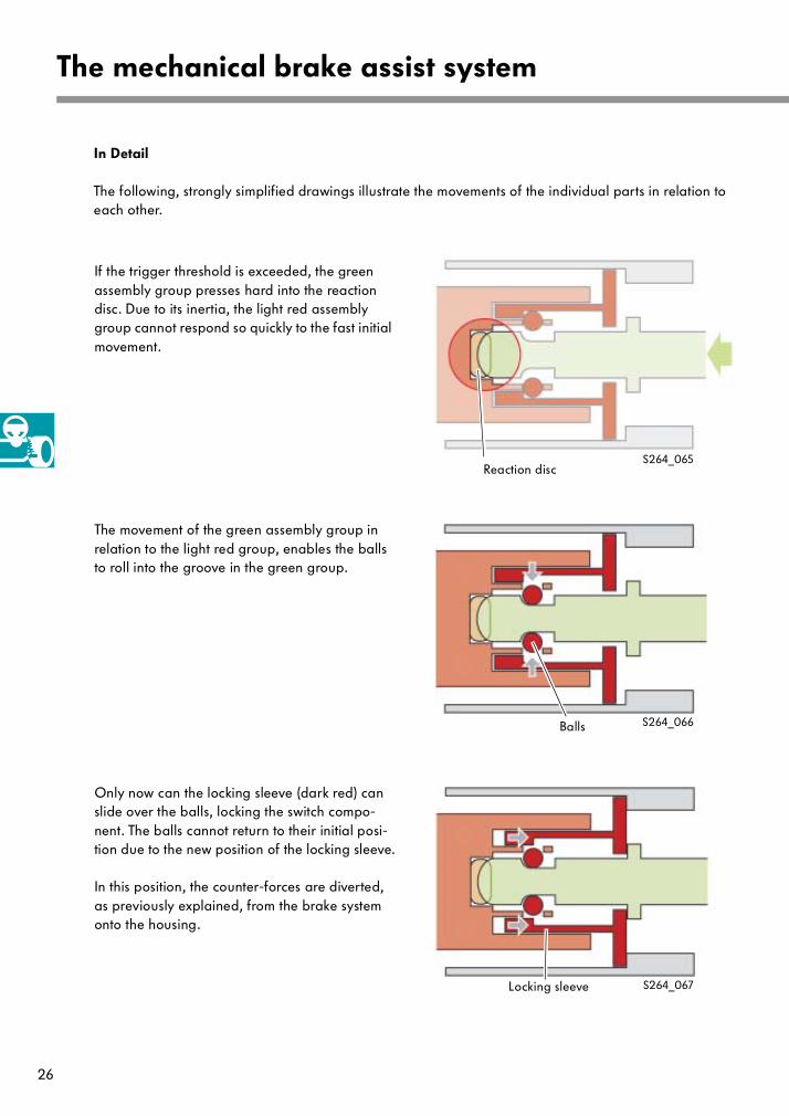
The following, strongly simplified drawings illustrate the movements of the individual parts in relation to each other.
If the trigger threshold is exceeded, the green assembly group presses hard into the reaction disc. Due to its inertia, the light red assembly group cannot respond so quickly to the fast initial movement.
The movement of the green assembly group in relation to the light red group, enables the balls to roll into the groove in the green group.
Only now can the locking sleeve (dark red) can slide over the balls, locking the switch compo-nent. The balls cannot return to their initial posi-tion due to the new position of the locking sleeve.
In this position, the counter-forces are diverted, as previously explained, from the brake system onto the housing.
Reaction disc
Balls
Locking sleeve S264_067
S264_066
S264_065

27
Because the entire mechanism moves further back within the brake servo, the light red part now moves in relation to the dark red part. Con-sequently, the locking sleeve releases the balls.
In the last phase of the movement, the balls are pressed back into their initial position by the green assembly group.
The emergency brake assist function is switched off.
If the driver takes his foot from the brake pedal, both red and the green assemblies move back together until the stop rests against the housing.
Concluding the brake assist function
Stop
Housing
Locking sleeve releases the balls
Green assembly group again in the initial posi-tion
S264_064
S264_063
S264_062
28
Service
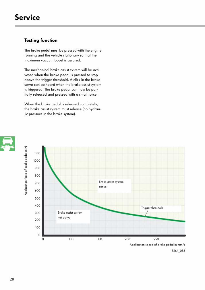
Testing function
The brake pedal must be pressed with the engine running and the vehicle stationary so that the maximum vacuum boost is assured.
The mechanical brake assist system will be acti-vated when the brake pedal is pressed to stop above the trigger threshold. A click in the brake servo can be heard when the brake assist system is triggered. The brake pedal can now be par-tially released and pressed with a small force.
When the brake pedal is released completely, the brake assist system must release (no hydrau-lic pressure in the brake system).
App
lica
tion
forc
e of
bra
ke p
edal
in N
0
100
200
300
400
500
600
700
800
900
1000
0 100 150 200 250
Application speed of brake pedal in mm/s
Brake assist system
active
Brake assist system
not active
Trigger threshold
S264_083
1100

29
Test your knowledge
1. What is the function of the brake assist system?
a It prevents the wheels from locking during emergency braking.
b It supports the driver when braking in emergency situations.
c It indicates to the driver how hard he must brake.
d It attains the greatest possible braking effect while maintaining steering ability.
2. In which vehicles is the hydraulic brake assist system currently installed?
a Golf
b Polo 2002
c Passat W8
d Lupo 3L
3. The signals of which sensors are used for evaluating the trigger conditions?
a Brake pressure sender
b Engine speed sender
c Speed sensors on wheels
d ABS pressure sender
e Brake light switch

30
Test your knowledge
cb
d
a =
b =
c =
d =
4. Identify the components in the drawing.
a
5. What is the effect of the mechanical brake assist system based on?
a The intake manifold vacuum works against the brake force so that the driver does not feel anycounter-force in the brake pedal.
b The counter-force from the pressure build-up in the brake system is diverted to the control housing.
6. Which conditions must be fulfilled to activate the mechanical brake assist system?
a The application force must be sufficiently great when the application speed is low.
b The application speed must be sufficiently great when the application force is small.
c The activation condition depends entirely on the distance the pedal moves.

31
NotesAnswers:1. b, d2. b, c
3. a, c, e4.a = Accumulatorb = ESP (brake pressure) switch valve N225
c = ESP high-pressure valve N227d = Return flow pump5. b
6. a, b
For internal use only © VOLKSWAGEN AG, Wolfsburg
All rights reserved. Technical specifications subject to change without notice.
140.2810.83.20 Technical status 09/01
❀ This paper was produced from
non-chlorine-bleached pulp.
264