installation instructions 1933-1934 ford car only crossmember kit (this kit will not fit pick-up...
TRANSCRIPT
Installation Instructions 1933-1934 Ford Car ONLY Crossmember Kit
(This Kit will not fit Pick-up Trucks!)
Please read these instructions completely BEFORE starting your installation.
Remember the basic rule for a successful installation: Measure Twice, Weld Once!
1
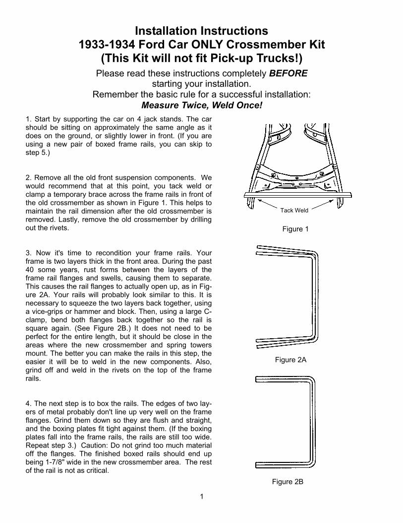
1. Start by supporting the car on 4 jack stands. The car should be sitting on approximately the same angle as it does on the ground, or slightly lower in front. (If you are using a new pair of boxed frame rails, you can skip to step 5.) 2. Remove all the old front suspension components. We would recommend that at this point, you tack weld or clamp a temporary brace across the frame rails in front of the old crossmember as shown in Figure 1. This helps to maintain the rail dimension after the old crossmember is removed. Lastly, remove the old crossmember by drilling out the rivets. 3. Now it's time to recondition your frame rails. Your frame is two layers thick in the front area. During the past 40 some years, rust forms between the layers of the frame rail flanges and swells, causing them to separate. This causes the rail flanges to actually open up, as in Fig-ure 2A. Your rails will probably look similar to this. It is necessary to squeeze the two layers back together, using a vice-grips or hammer and block. Then, using a large C-clamp, bend both flanges back together so the rail is square again. (See Figure 2B.) It does not need to be perfect for the entire length, but it should be close in the areas where the new crossmember and spring towers mount. The better you can make the rails in this step, the easier it will be to weld in the new components. Also, grind off and weld in the rivets on the top of the frame rails. 4. The next step is to box the rails. The edges of two lay-ers of metal probably don't line up very well on the frame flanges. Grind them down so they are flush and straight, and the boxing plates fit tight against them. (If the boxing plates fall into the frame rails, the rails are still too wide. Repeat step 3.) Caution: Do not grind too much material off the flanges. The finished boxed rails should end up being 1-7/8" wide in the new crossmember area. The rest of the rail is not as critical.
Figure 2A
Figure 1
Figure 2B
Tack Weld

Installation Instructions 1933-1934 Ford Car ONLY Crossmember Kit
2
5. Using the center rivet hole from the old cross-member or the rear top hole from the fender bracket, mark a line around the outside of the frame rail. This is your axle centerline. (See Figure 3.) If you purchased a complete I.F.S. Package from HEIDTS, it was supplied with Full Lower A-Arms. Begin by installing the Lower A-Arms onto the crossmember. The holes where the lower control arms attach to the Crossmember must be enlarged to 5/8”. Mount the Crossmember Spacers and the Rear Spacers which were supplied with the Lower Control Arms onto the Crossmember as shown in Figure 4 using the supplied Inner Bushing Bolts, Nuts and a temporary spacer under the Nuts. DO NOT use the A-Arms for this operation as the welding heat will melt the rubber bushings. Tighten the Bolts and Nuts tight. Weld the Rear Spacers to the Crossmember all around. Weld the Crossmember Spacers as far as possible inside the crossmember on both ends. Position the Gussets horizontally, not vertically, against the Rear Spacers and the back of the Crossmember. Weld Gussets to Spacers and Crossmember. When it cools, remove the bolt. 6. Now it is time to start fitting the new crossmem-ber. Slip it into the frame, center it on the scribed axle center line (Figure 5). If it does not fit, check that your frame is the correct width. It should be 27-3/8" wide at the axle center line (scribed line). If it is that dimension, then grind the sides of the cross-member until you can get the crossmember in place, as shown. Tack weld in place, check location, then weld in place, welding all around both ends, top, sides, and bottom. If you installed a temporary brace across the rails, you can now remove it.
Figure 4
Figure 5
Figure 3

Installation Instructions 1933-1934 Ford Car ONLY Crossmember Kit
3
7. Next are the spring towers. They sit on top of the frame rails, and are located as shown in Figure 6, (1-3/4", forward of the cross-member measuring from the front of the crossmember to the front of the spring tower). Clamp in place, double check your dimensions, then weld all around, including the gusset flanges on the sides of the rails. For added strength, you can also weld the inside of the gusset flanges. (Hint: Before you install the spring towers, you can weld up and grind flush the old fender bracket holes and the one splash apron hole which are covered by the spring towers, as they will no longer be used.) Figure 6
1-3/4”
8. The radiator support tabs are next. Clamp the two tabs to a flat bar as shown in Figure 7. They should be spaced so the holes are spaced 19-3/16" apart, center to center. Position the tab and bar assembly up into the frame, so the outer edge of the tab is against the inside bottom edge of the frame. If they fall under the frame, grind the outside edge of the tabs so the edges of the tabs end up inside the bottom inside edge of the frame rail. You will see that the actual radiator mounting surface is tilted back, to give the radiator the correct mounting angle.
Figure 7
Installation Instructions 1933-1934 Ford Car ONLY Crossmember Kit
4
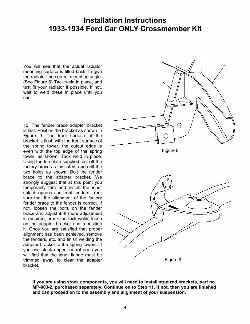
10. The fender brace adapter bracket is last. Position the bracket as shown in Figure 9. The front surface of the bracket is flush with the front surface of the spring tower, the cutout edge is even with the top edge of the spring tower, as shown. Tack weld in place. Using the template supplied, cut off the factory brace as indicated, and drill the two holes as shown. Bolt the fender brace to the adapter bracket. We strongly suggest that at this point you temporarily trim and install the inner splash aprons and front fenders to in-sure that the alignment of the factory fender brace to the fender is correct. If not, loosen the bolts on the fender brace and adjust it. If more adjustment is required, break the tack welds loose on the adapter bracket and reposition it. Once you are satisfied that proper alignment has been achieved, remove the fenders, etc. and finish welding the adapter bracket to the spring towers. If you use stock upper control arms you will find that the inner flange must be trimmed away to clear the adapter bracket.
Figure 8
You will see that the actual radiator mounting surface is tilted back, to give the radiator the correct mounting angle. (See Figure 8) Tack weld in place, and test fit your radiator if possible. If not, wait to weld these in place until you can.
Figure 9
If you are using stock components, you will need to install strut rod brackets, part no. MP-003-2, purchased separately. Continue on to Step 11. If not, then you are finished and can proceed on to the assembly and alignment of your suspension.
Installation Instructions 1933-1934 Ford Car ONLY Crossmember Kit
5
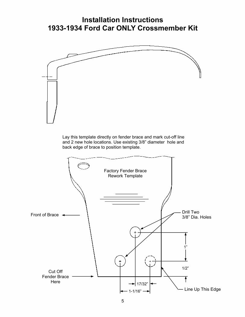
Lay this template directly on fender brace and mark cut-off line and 2 new hole locations. Use existing 3/8” diameter hole and back edge of brace to position template.
1-1/16”
17/32”
1”
1/2”
Factory Fender Brace Rework Template
Cut Off Fender Brace
Here
Line Up This Edge
Front of Brace Drill Two 3/8” Dia. Holes
