installation instruction hart add-on module
TRANSCRIPT

HART Add-On Module
Installation Instruction

Installation Instruction - Translation
HART Add-On Module Typs 17-A1Z0-0005, B7-A2Z0-0033 and G7-A0Z0-0007
Version for: Non hazardous areas
ATEX/IECEx Zone 1 and Zone 2
UL Class I Division 1 and Division 2
Document No.: B1-A2Z0-7N0001 / 400570 Revision A - Status: 29. September 2016
Reservation: Technical data subject to change without notice. Changes, errors and misprints may not be used as a basis for any claim for damages.
Content Pages
English 1-12
BARTEC GmbH Max-Eyth-Straße 16 97980 Bad Mergentheim GERMANY
Phone: +49 7931 597-0 Fax: +49 7931 597-119
Contact: [email protected] Download: www.bartec.de
Installation Instruction (Translation)
HART Add-On Module Typs 17-A1Z0-0005 , B7-A2Z0-0033 and G7-A0Z0-0007
Technical data subject to change . Revison A - 09/2016 EN 1/12
Basic Information
Read carefully before putting the device into operation.
The Installation Instruction is a fixed part of the product. It must be kept in the direct vicinity of the device and the installation, operating and service staff must have access to it at all times.
More detailed instructions of use can be found at www.bartec.de as well as the current versions of the datasheets, user manual, certificates and EU declaration conformity or may be requested directly from BARTEC GmbH.
Knowledge of the safety and warning information and the strict compliance with it is essential for safety installation and use. Injuries and material damage can be avoided by circumspect handling and systematically following the instructions.
The BARTEC company reserves the right to carry out technical changes at any time.
Maintenance and Repairs The pertinent erection and operating provisions for electrical systems must be observed! Repairs to explosion-protected devices may only be performed by authorised personnel with original spare parts and according to the state of the art. The applicable provisions must be observed in this respect.
Inspections According to EN/IEC 60079-17 and EN/IEC 60079-19, the operator of electrical systems in potentially explosive atmospheres is obliged to have these inspected by an electrician to ensure correct condition.
Warranty If non-specified components are used, the explosion protection will no longer be guaranteed. In the case of externally procured parts, it is not guaranteed that these have been designed and manufactured in accordance with their load and requisite safety.
Disposal As professional electrical devices, our devices are intended exclusively for commercial use, so-called B2B devices, in accordance with the WEEE Directive. Observe the national waste disposal regulations when disposing of the devices. All products purchased from us can be returned to us by our customers for disposal. The sender shall bear the costs of postage and packaging.

Installation Instruction (Translation)
HART Add-On Module Typs 17-A1Z0-0005 , B7-A2Z0-0033 and G7-A0Z0-0007
Technical data subject to change . Revison A - 09/2016 EN 2/12
Safety Instructions The HART Add-On Module may only be operated in a clean, undamaged condition and may only be deployed within the specified temperature class and the temperature range indicated for it. Special Conditions for explosion protection must be observed. The assembly/dismantling must be conducted by qualified personnel authorised and trained to install electrical components in potentially explosive areas. The use in areas other than those specified or alteration of the product releases BARTEC from liability for defects and further liability. Modifications and changes to the module are not permitted. The generally applicable statutory regulations and other binding guidelines on occupational health and safety, on accident prevention and on environmental protection must be complied with.
Danger, Warning and Note Symbols Safety instructions and warnings are specially highlighted in this installation instruction and marked by symbols.
DANGER
The DANGER sign draws attention to a direct threat which if not avoided will lead to death or very serious injuries.
WARNING
WARNING draws attention to a possible threat which if not avoided can lead to death or very serious injuries.
CAUTION
CAUTION draws attention to a possible danger which if not avoided can lead to slight or minor injuries.
ATTENTION
ATTENTION draws attention to a potentially damaging situation which if not avoided can cause damage to the equipment or to objects in its vicinity.
Important instructions and information on effective, economical & environmentally compatible handling.

Installation Instruction (Translation)
HART Add-On Module Typs 17-A1Z0-0005 , B7-A2Z0-0033 and G7-A0Z0-0007
Technical data subject to change . Revison A - 09/2016 EN 3/12
Marking, test certificate, and standards Note: Full information see "user manual" tablet PC.
Type 17-A1Z0-0005 for tablet PC "Agile X IS"
ATEX Zone 1 II 2G Ex ia [ia Ga] IIC T4 Gb EPS 15 ATEX 1 069 X
IECEx Zone 1 Ex ia [ia Ga] IIC T4 Gb IECEx EPS 15.0065X
NEC (USA/Canada) Class I Div 1 Groups A, B, C, D T4 CSA 70045374
Type G7-A0Z0-0007 for tablet PC "Agile"
ATEX II (2)G [ia Ga] IIC EPS 15 ATEX 1 069 X
IECEx [Ex ia Ga] IIC IECEx EPS 15.0065X
NEC [Ex ia Ga] II C CSA 70045374
Special conditions on the test certification EPS 15 ATEX 1 069 X for typs 17-A1Z0-0005 and G7-A0Z0-0007
- Maximum ambient temperature range: -20 °C to +50 °C. - The HART add on modules shall be protected against strong charge generating processes. - It is allowed to connect the HART add on module to non certified HART circuits outside
hazardous areas. Um = 60 V shall never be exceeded. The user is responsible to meet this condition.

Installation Instruction (Translation)
HART Add-On Module Typs 17-A1Z0-0005 , B7-A2Z0-0033 and G7-A0Z0-0007
Technical data subject to change . Revison A - 09/2016 EN 4/12
Type B7-A2Z0-0033 for tablet PC "Agile X"
ATEX Zone 2 and 22 II 3G Ex ic [ia Ga] IIC T4 Gc
II 3D Ex ic [ia Da] IIIB T135 °C Dc EPS 15 ATEX 1 823 X
IECEx Zone 2 and Zone 22 Ex ic [ia Ga] IIC T4 Gc
Ex ic [ia Da] IIIB T135 °C Dc IECEx EPS 15.0010X
NEC (USA/Canada) Class I Division 2 Groups A, B, C and D UL File E321557
Special conditions on the test certification EPS 15 ATEX 1 823 X for type B7-A2Z0-0033
- Maximum ambient temperature range: -20°C to +50°C. - External connectors shall never be used in hazardous areas. The battery shall never be
removed, changed or charged in hazardous areas. The RFID module shall never be mounted or removed in hazardous areas. The flash (LED) shall never be used as a permanent light in hazardous areas.
- The apparatus shall be protected against mechanical impact, excessive UV-light and strong charge generating processes.
- In combination with Bartec accessory 03-9849-0130 (hand strap) the device is only suited for gas group IIA.
- It is allowed to connect the HART add on module to non certified HART circuits outside hazardous areas. Um = 60 V shall never be exceeded. The user is responsible to meer this condition.

Installation Instruction (Translation)
HART Add-On Module Typs 17-A1Z0-0005 , B7-A2Z0-0033 and G7-A0Z0-0007
Technical data subject to change . Revison A - 09/2016 EN 5/12
Device / system specification
HART interface UI ≤ DC 30 V
II ≤ 130 mA
PI ≤ 1 W
U0 ≤ DC 3 V
I0 ≤ 10 mA
P0 ≤ 5 mW
Um ≤ DC 60 V
max. cable length: 1.8 m
Size (weight x length x height) 125 mm x 125 mm x 24 mm
Weight 200 g
Protection class (IEC 60529) Mounted on tablet PC: IP54 Connector strip (PoGo Pins): IP20
Operating temperature
inside hazardous areas outside hazardous areas
-20 °C to +50 °C -20 °C to +60 °C
Storage temperature -30 °C to +70 °C
Operating humidity 30 % to 95 % (non-condensing)

Installation Instruction (Translation)
HART Add-On Module Typs 17-A1Z0-0005 , B7-A2Z0-0033 and G7-A0Z0-0007
Technical data subject to change . Revison A - 09/2016 EN 6/12
Introduction
The intrinsically safe combination of the tablet PC system and the newly developed HART Add-On Module makes it possible to perform diagnostics, set parameters and manage field devices much more quickly and efficiently. The HART modem is used as an add-on module for the tablet PC system in its extension interface. Since the user is now able to switch safely between the Ex and non-Ex area, only one device is then needed for the wireless uploading or adjusting of the field devices distributed there, completely independently of the control system. Scope of delivery: - 1x HART Add-On Module - 2x Pan head screw M3x10 - 2x Pan head screw M3x7 - 2x Truss head screw M3x7 - 2x Connection cable - 2x Test probes - 1x Installation instruction HART Add-On Module
DANGER The extension interface of the tablet PC must always be sealed in a potentially explosive atmosphere! There is a risk of explosion!
Only remove or mount the cover of the extension module outside the potentially explosive atmosphere.
Only assemble/dismantle the HART Add-On Module outside the potentially explosive atmosphere.
Risk of short circuiting if the screws supplied with delivery are not used. Carry out the correct assembly for the attachment.
Use the screws supplied with delivery. All screws must be used to ensure the safe mechanical assembly of the HART Add-On Module on the tablet PC. Store the cover of the extension port safely.

Installation Instruction (Translation)
HART Add-On Module Typs 17-A1Z0-0005 , B7-A2Z0-0033 and G7-A0Z0-0007
Technical data subject to change . Revison A - 09/2016 EN 7/12
Installation HART Add-On Module
Only assemble/dismantle the HART Add-On Module outside the potentially explosive atmosphere. Only use the HART Add-On Module for the purpose that they have been tested and certificated by BARTEC..
Avoid data losses! Do not just switch the tablet PC using the "ON/OFF" switch.
1. Shut the tablet PC down using the operating system.
2. Place the tablet PC on the display side, taking care that no parts nearby scratch the screen.
3. Remove the cover on the extension interface.
4. Remove the top two screws on the I/O interface cover.
5. Unpack the HART Module (the srews supplied for mounting are in the packaging).
6. Place the HART Add-On Module on the extension interface.

Installation Instruction (Translation)
HART Add-On Module Typs 17-A1Z0-0005 , B7-A2Z0-0033 and G7-A0Z0-0007
Technical data subject to change . Revison A - 09/2016 EN 8/12
7. Fasten the HART Add-On Module using the six screws supplied. Torque 3 Nm.
8. Visual inspection of the HART Add-On Modules to ensure correct positioning and assembly.
9. Switch the tablet PC on using the "ON/OFF" button.
Optional: Attach hand strap. (Material No. 03-9849-0130) 10. Losen the top screw that holds the
HART Add-On Module in place. 11. Place the hand strap on and
fasten using the four M3x8 (supplied) pan head screws. Torque: 3 Nm.
Do not assemble or remove the hand strap in a potentially explosive atmosphere.
DANGER
Zone 2: Tablet PC Agile X There is a risk of fatal injury in an explosive atmosphere! The hand straps may only be
used in areas with gas group IIA.

Installation Instruction (Translation)
HART Add-On Module Typs 17-A1Z0-0005 , B7-A2Z0-0033 and G7-A0Z0-0007
Technical data subject to change . Revison A - 09/2016 EN 9/12
Setting up/activating the HART Add-On Module
Switching the tablet PC on. Press the ON/OFF button for three
seconds.
Activating the HART Add-On Module. (1) Click on "Hottab" on the start
screen to start the application.
(2) Click in the menu on the option "Device ON/OFF".
(3) Select "Ext.Module" to active the extension interface.
(orange = ON; White = OFF)
(4) Power set to ON.
In up-to-date versions of the operating system the driver has already been integrated in the image. With older versions the driver must be installed manually using the device manager.
Affects "Hottab" versions from 1.40 and higher. Older versions can be updated..
Installation Instruction (Translation)
HART Add-On Module Typs 17-A1Z0-0005 , B7-A2Z0-0033 and G7-A0Z0-0007
Technical data subject to change . Revison A - 09/2016 EN 10/12
Downloading and installing driver software
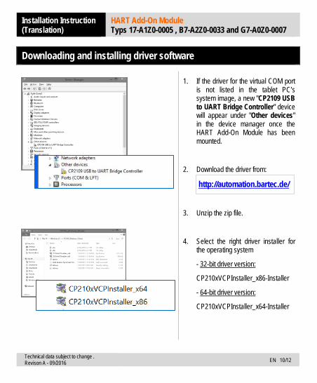
1. If the driver for the virtual COM port is not listed in the tablet PC’s system image, a new "CP2109 USB to UART Bridge Controller" device will appear under "Other devices" in the device manager once the HART Add-On Module has been mounted.
2. Download the driver from:
http://automation.bartec.de/
3. Unzip the zip file.
4. Select the right driver installer for the operating system
- 32-bit driver version:
CP210xVCPInstaller_x86-Installer
- 64-bit driver version:
CP210xVCPInstaller_x64-Installer

Installation Instruction (Translation)
HART Add-On Module Typs 17-A1Z0-0005 , B7-A2Z0-0033 and G7-A0Z0-0007
Technical data subject to change . Revison A - 09/2016 EN 11/12
5. The "User Account Control" (UAC) window opens.
6. Start installation by clicking on "Yes".
7. Continue installation in the
"CP210x USB to UART Bridge Driver Installer" window by clicking on "Next".
8. Accept the licence conditions by clicking on "I accept this agreement" and confirm by clicking on "Next".

Installation Instruction (Translation)
HART Add-On Module Typs 17-A1Z0-0005 , B7-A2Z0-0033 and G7-A0Z0-0007
Technical data subject to change . Revison A - 09/2016 EN 12/12
9. The "The Drivers were successfully installed on this computer" message appears in the window.
Complete installation by clicking on "Finish".
10. Once the driver has been installed, the HART Add-On Module can be found in the device manager under:
"Ports (COM & LPT)" with the designation "Silicon Labs CP210x USB to UART Bridge".


EN_B
1-A2
Z0-7
N000
1-09
/201
6-Au
tom
atio
n-40
0570
Your partner
for safety
technology.
Challenge us!
BARTEC GmbHGermany
Phone: +49 7931 597 0Fax: +49 7931 597 119
Max-Eyth-Str. 16 97980 Bad Mergentheim