profis etting started installation instruction manual - hilti · pdf fileprofis installation...
TRANSCRIPT

Getting started
Profis installation Instruction Manual page 1
PROFIS INSTALLATION INSTRUCTION MANUAL

Getting started
Profis installation Instruction Manual page 2
Conditions of Use: Provided pursuant to Hilti’s Terms and Conditions of Sale. Software specifications, system listings, functionality and appearance are subject to change.
Legal DisclaimerTypical details shown are examples only and not for construction, contact Hilti for detailed design to meet project specific requirements. All loading and design criteria supplied by customer is assumed accurate. Only the stated Design Assumptions were considered, and must be verified by the responsible Engineer of Record (EOR). The basis of Hilti component and connection design is the published data in the current Hilti Technical Guide, including material and cross-section properties, allowable load values, factors of safety, methods of calculation, and limiting factors. The EOR must verify suitability for any specific application, and the capacity of the supportive structure to receive the shown configuration and associated reaction loads. Modification to components and/or design may alter performance and must be evaluated by the EOR.
Contents
Chapter 1: Getting started Page 3Section 1.1 Creating a project
Section 1.2 Hilti button
Chapter 2: Template design Page 6Section 2.1 Manage pipe layer window
Section 2.2 Projects
Section 2.3 Basis tab
Section 2.4 Design tab
Section 2.5 Calculation tab
Section 2.6 View tab
CAD model viewer
Reports options window
Chapter 3: 3D Design Page 18Section 3.1 Dimensions
Section 3.2 Beams
Section 3.3 Pipes, airducts, and cable trays
Section 3.4 Pipe properties window
Section 3.5 Airduct properties window
Section 3.6 Cable tray properties
Section 3.7 Loads
Section 3.8 Load properties window
Chapter 4: Channel Page 27
Chapter 5: BIM/CAD Export Page 30

GETTING STARTEDChapter 1
Section 1.1 Creating a project Page 4
Section 1.2 Hilti button Page 5

Getting started
Profis installation Instruction Manual page 4
Creating a project
To create a new project, select one of the following:
Click the “Hilti” button to create a new project or assembly, open an existing project, or change settings (Language, Units, Portfolio, etc.) (see page 5).
-or-
Select an assembly designer option from the “Quickstart Assistant” to create a new project.

Getting started
Profis installation Instruction Manual page 5
Hilti button
Menu
Top to bottom:
New: Create a new project, sub project, assembly, or parts list
Open: Open an existing project, a favorite project, or a recent project
Save: Save the current project in its previous location
Save As: Save a project in a new location or save one as a favorite
Print: Open the “Print preview” and print the selection
Manage: Manage customers in the customers list or manage the favorites list
Import: Import files for list prices or translations
Close project: Close the current project
Options
Settings: Select language, enable/disable auto save, set auto save interval, etc.
Units: Selects units to use for length, weight, load, torque, and stress as well as the number of decimal places to use for each
Parts list: Select which fields to sum on the parts list, sales price factor, etc.
Parts list layout: Select which fields to display/export on parts lists and the order they should appear in
Catalogue: Select the currency and catalog portfolio to use
Resources: Check for updates, view version information, activate other PROFIS software keys, etc.
Calculation: Set proxy settings (if required) for accessing the cloud calculations
Channel 3D: Select to enable/disable hardware acceleration, show/hide fixed positions, and show/hide the base material in CAD models

TEMPLATE DESIGNChapter 2
Section 2.1 Manage pipe layer window Page 8
Section 2.2 Projects Page 10
Section 2.3 Basis tab Page 11
Section 2.4 Design tab Page 12
Section 2.5 Calculation tab Page 14
Section 2.6 Reports options window Page 15
Section 2.7 View tab Page 16
Section 2.8 CAD model viewer Page 17

Template design
Profis installation Instruction Manual page 7
Template design
Select Material Type “MI/MQ (Heavy/Light)”
Change Application type to “Piping” or “Cable trays”
Change Building material to “Concrete” or “Steel”
To open a template design
Click an application type, then select a template to load
The template will open in the “Manage Pipe Layers” window (page 8)
Use one of the following standard template designs

Template design
Profis installation Instruction Manual page 8
Manage Pipe Layer window
Dimension type
Axis to axis: Specify measurements from center to center
Surface to surface: Specify measurements from edge to edge
Add/Remove pipe
Add a pipe above or below the support or delete a pipe
Pipe properties
Edit type and size of pipe
Insulation properties
Select insulation material and thickness (if applicable)
Other properties
Add or remove insulation and pipe fill by selecting the boxes
Spacing
Edit spacing between supports along pipe
Run channel pre-calculation
Runs an initial calculation and reports the max utilization percentage and deflection utilization percentage for the channel
Dimension orientation
Horizontal: Specify measurements in the horizontal direction
Vertical: Specify measurements in the vertical direction
Pipe layer
Select a pipe to edit attributes (selection highlighted in red) or edit dimensions
Pipe support properties
Select support type and assembly options
Weight
View supported weight and add additional weight if necessary
Manage Pipe Layer window allows user to manage pipe properties and insulation properties

Template design
Profis installation Instruction Manual page 9
Loads
Click on “Loads” tab to add/modify/remove loads in addition to dead loads

Template design
Profis installation Instruction Manual page 10
Projects
Modification
Add a new line to the parts list
Note: To delete a line, click on the line in the table to highlight it and press the “Delete” key.
Project
Select to open the project information and parts list for all assemblies in the project.
When a project or assembly is selected, right click for additional options (New, Copy, Rename, Delete, etc.)
Assembly
Select to edit the assembly
Picture
Insert pictures associated with the project.
Note: Selecting the “Print” option will include the images on reports.
Documents
Attach documents associated with the project.
Catalogue
Item description and number.
Parts list
Displays parts required for the project
Note: Right click for additional options (add column, remove column, sort, etc.).
Calculations
Sum: Provides sum of lengths
Round to sales quantity: Total length of MI girders to purchase
Renewal of aggregation: Refreshes the parts list with changes made in the assemblies
Extras
Refresh prices from catalog: Prices from HOL
Refresh all prices in project: Price based on BOM
Excel export: Exports the parts list to an Excel file
AutoCAD export: Exports the parts list to an AutoCAD object
Hilti Online
Opens Hilti Online in a web browser with parts placed in the shopping cart
Report
Creates a PDF file with the parts list and cut plan for beams
Customer
Information appears on reports generated for the project. Use the button to insert customer information from the customer list
Project
Add Project Description (Name, Number, etc)
How to navigate through a project to set project properties. Double click on the Project 1 (Project name) in project tree pane.

Template design
Profis installation Instruction Manual page 11
Basis tab
Design Basis
Design basis: Select the basis of design for calculations
Load combination design basis: Select the load combination basis of design to use for calculations
Load combinations: View the load combination selected in tabular format
Channel System
System: Select channel systems to include in calculations
Material type: Select channel material or finish to include in calculations
Building material: Select base material supports will connect to
Note: Not all material types are available for each channel system.
Expand project 1 and then double click on bcMQ5c to get to the Basis tab or project design screen

Template design
Profis installation Instruction Manual page 12
Design tab
Tools
Selector: Use to select and edit features in the model
Dimension: See page 19
Guide lines: Adds 3D coordinate lines to a node. Beams can be attached to these guide lines
Clear guide lines: Removes all guide lines in the model
Copy load: With a load selected, this will duplicate the load and place it next to the current one
Move origin: When selected, click and hold in the model view to pan the origin
Set zero point: Select a node to move the zero point of the main axes
Objects
Add beam: See page 20
Add node: Click on an existing beam to add a node
Add fixed support: Click on an existing node to add a fixed support (resists forces and moments)
Add pinned support: Click on an existing node to add a pinned support (resists forces only)
Loads
Add pipe: See page 21
Add custom load: See page 25
Add airduct: See page 21
Add cable tray: See page 21
CAD
View CAD construction: Opens the “CAD Model Viewer” (see page 18)
View shop drawing: Creates a shop drawing with CAD models and a parts list of the assembly. Includes the option to insert and maintain a revision block
Quick access toolbar
See page 4
Project tree
See page 10
Design tab enables user to change dimensions, add/modify objects, view construc-tion.

Template design
Profis installation Instruction Manual page 13
Supports: To edit supports, double click to open the “Support Properties” window. This displays the support geometry and loads (after a calculation is run) and allows for selection of base material connector and fixation method
Beams: To edit beams, double click to open the “Beam Properties” window. This displays the beam stresses and loads (after a calculation is run) and section data and allows for selection of channel type and rotation
Dimensions: To edit dimensions, see page 19
Loads
Displays the type, description, position, width, load type, forces, and moments of loads in the assembly. The position attributes can be edited
Note: When a custom load is inserted, the position, width, load type, forces, and moments can be edited
Supports
Displays the type and location of supports in the assembly
Beams
Displays the type, start and end point locations, length, and weight of beams in the assembly. The start and end point locations can be edited
Nodes
Displays the type and location of each node in the assembly. The location attributes can be edited
Nodes: To edit nodes, double click to open the “Node Properties” window. This displays the node geometry and loads (after a calculation is run) and allows for selection of connection type

Template design
Profis installation Instruction Manual page 14
Calculation tab
Calculation
Static calculate: Creates a calculation (using the “Model Options” selected) and makes the Report tab available
Clear calculation results: Removes current calculation to allow for changes and recalculation
Short
Check when pipes are present and uncheck when pipes are absent
Report
Complete: Complete report
Short: Creates a shop drawing of the assembly
Options
Model Options: Adjust defaults for maximum beam displacement, maximum cantilever allowable deflection, and minimum deflection limit
Short

Template design
Profis installation Instruction Manual page 15
Reports options window
Print Reports
Top to bottom:
Calculation summary: Includes calculations for deflection and combined loading on beams as well as forces and moments at connections and supports in the report
Member design checks: Includes compression, tension, shear, torsion, flexure, and combined loading calculations for beams in the report
Displacement: Includes displacement calculations for beams in the report
Support load: Includes reaction forces and moments at the connection to the structure in the report
Section load: Includes calculations for forces and moments along the beam lengths in the report
Section load images: Includes images reflecting the normal and shear loads, moments, and torsion along the beam lengths in the report
Used check for members acc. AIS S100-2010: Provides formulas used to perform AISI code check on members
Save report
Save the generated report to the computer in PDF format
Save settings
Save the selected options as default
Click on “Complete” to get report options

Template design
Profis installation Instruction Manual page 16
View tab
Aspect
3D View: Displays the model in a perspective view
3D View ISO: Displays the model in an isometric view
2D Front view: Displays the XZ plane orthographic view
2D Side view: Displays the YZ plane orthographic view
2D Top view: Displays the XY plane orthographic view
View CAD construction: Opens the “CAD Model Viewer” to view, print, or export the assembly (see page 17)
View
Zoom in: Zooms in on the model origin
Zoom out: Zooms out from the model origin
Zoom loads in: Increases the scale of the load objects
Zoom loads out: Decreases the scale of the load objects
Mounting Type
Floor: Configures background colors to view from above the model
Ceiling: Configures background colors to view from below the model
Extras
Layer dialog: Opens the “Layers” window where objects (Dimensions, Loads, Elements, etc.) can be hidden or displayed
Show/Hide guide lines: Hides or displays all guide lines present on the model
Rotation
Rotates the view vertically or horizontally about the origin. The middle button resets the zoom, rotation, and origin to default
Holding the right mouse button and moving the mouse rotates the view about the origin.

Template design
Profis installation Instruction Manual page 17
CAD model viewer
IconsLeft to right:• Zoom extents• Zoom window (click and drag inside the
viewport to draw the window)• Zoom in• Zoom out• Show/hide coordinate system icon• Home view• Left view• Right view• Front view• Back view• Top view• Bottom view• Detailed view• Simplified view
By right-clicking inside the viewer, additional options appear (Rotate, Pan, Print, Copy to Clipboard, etc.)
System
Select the CAD program the model will be exported to
Note: When exporting a 2D drawing, select the “Use 2D geometry” box before selecting the System so the correct options are available in the System list
Use 2D geometry
Uncheck to export a 3D model or check to export a 2D drawing of the model as it appears in the viewer
Show hidden lines
When exporting a 2D drawing, uncheck to hide hidden lines or check to display hidden lines
Options
Opens the “Settings” window to adjust attribute options including layer, color, and linetype
Export
With the CAD program open, click “Export” to create the object in the CAD program

3D DESIGNChapter 3
Section 3.1 Dimensions Page 19
Section 3.2 Beams Page 20
Section 3.3 Pipes, airducts, and cable trays Page 21
Section 3.4 Pipe properties window Page 22
Section 3.5 Airduct properties window Page 23
Section 3.6 Cable tray properties Page 24
Section 3.7 Loads Page 25
Section 3.8 Load properties window Page 26

3D Design
Profis installation Instruction Manual page 19
Select “Design basis” and “Load combination design basis”
Apply different load combinations using “Load combinations” table
To add a dimension in the drawing:
Click the “Dimension” button:
Select the first node
Select the second node
Select the location of the dimension label
To edit a dimension in the drawing:
Double click the dimension to change
Enter the new value
Note: Whenever possible, create dimensions from the origin to the node (as shown). When editing dimensions between nodes, the node closest to the origin will drive and the node farther away will be driven
Expert Design Mode enables the user to design virtually any configuration/any geometry using Hilti Modular Supports.
Add a new project or create a new project
Dimensions
3D design

3D Design
Profis installation Instruction Manual page 20
To add a beam in the drawing:
Click the “Add Beam” button:
Select the location of the first end of the beam
Note: The first beam node must be placed on the zero point or an existing beam
Select the location of the second end of the beam
Note: The line will turn green when the mouse is moved over a valid beam location (along a major axes, node guideline, another beam, etc.). The new beam will also snap to run along a guideline if the location of the second beam end is selected close to the guideline it will run along
To edit a beam in the drawing:
Position the beam using dimensions
Double click the beam to change beam properties (see page 13)
Beams

3D Design
Profis installation Instruction Manual page 21
To add a pipe, airduct, or cable tray in the drawing:
Click the “Add” button for the desired item:
Select the location on the beam
Move the mouse around the beam location to rotate the direction of attachment. Click to select an orientation. Do the same to select the direction of travel for the item
To edit a pipe, airduct, or cable tray in the drawing:
Position the load using dimensions (see page 19)
Double click the load to change the properties (see pages 22)
Pipes, airducts, and cable trays
3D Design
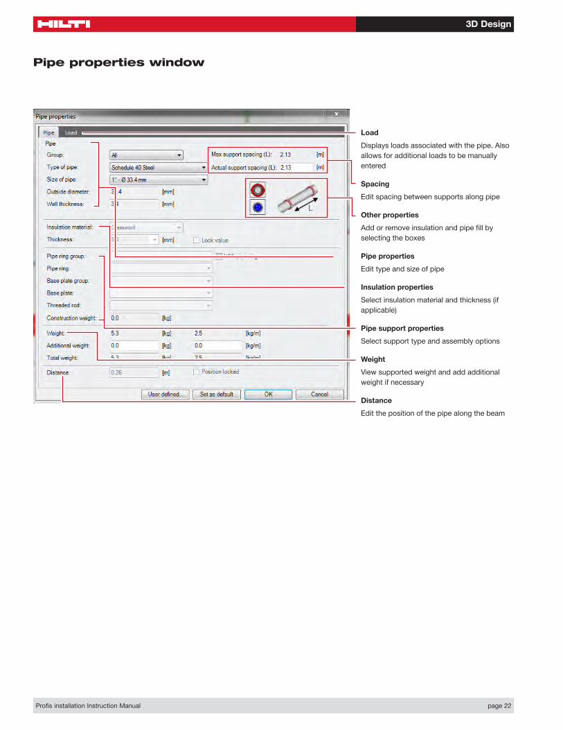
Profis installation Instruction Manual page 22
Load
Displays loads associated with the pipe. Also allows for additional loads to be manually entered
Spacing
Edit spacing between supports along pipe
Other properties
Add or remove insulation and pipe fill by selecting the boxes
Pipe properties
Edit type and size of pipe
Insulation properties
Select insulation material and thickness (if applicable)
Pipe support properties
Select support type and assembly options
Weight
View supported weight and add additional weight if necessary
Distance
Edit the position of the pipe along the beam
Pipe properties window

3D Design
Profis installation Instruction Manual page 23
Load
Displays loads associated with the pipe. Also allows for additional loads to be manually entered
Spacing
Edit spacing between supports along pipe
Other properties
Add or remove insulation and pipe fill by selecting the boxes
Pipe properties
Edit type and size of pipe
Insulation properties
Select insulation material and thickness (if applicable)
Weight
View supported weight and add additional weight if necessary
Airduct properties window

3D Design
Profis installation Instruction Manual page 24
Load
Displays loads associated with the pipe. Also allows for additional loads to be manually entered
Spacing
Edit spacing between supports along cable tray
Pipe properties
Edit type and size of cable tray
Weight
View supported weight and add additional weight if necessary
Cable tray properties
3D Design
Profis installation Instruction Manual page 25
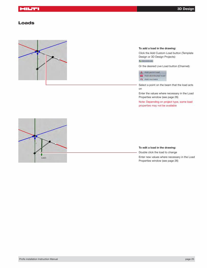
To add a load in the drawing:
Click the Add Custom Load button (Template Design or 3D Design Projects):
Or the desired Live Load button (Channel):
Select a point on the beam that the load acts on
Enter the values where necessary in the Load Properties window (see page 26)
Note: Depending on project type, some load properties may not be available
To edit a load in the drawing:
Double click the load to change
Enter new values where necessary in the Load Properties window (see page 26)
Loads

3D Design
Profis installation Instruction Manual page 26
Description
Descriptive text given to the load
Load type
Change the load type to be used in calculations
Note: Different load types are available depending on the Design Basis selected (see page 11)
Moments
Add moments about one or more of the axes
Note: The positive Z-axis is “down” in the normal model view
Forces
Add forces along one or more of the axes
Note: The positive Z-axis is “down” in the normal model view
Load properties window
Add
Click to add another line for an additional load type.
Remove
Click to remove the selected load type line.
Position
Position of the load along the selected beam.
Distributed load properties
Distributed load is applied to the entire length of the beam
Width
Width of a distributed load.

CHANNELChapter 4

Channel
Profis installation Instruction Manual page 28
Quick Access Toolbar (See page 4)
Design Basis (See page 11)
Applications
Standard templates for various types of channel construction
Static system
Beam length: Define channel length either in the ribbon or using the dimension on the model (see page 20)
Number of supports: Determine number of supports present in model. Positions are edited using dimensions on the model (see page 16)
Channel system
Channel system: Select channel systems to include in calculations
Material type: Select channel material or finish to include in calculations
Note: Not all material types are available for each channel system
Live loads
Selecting a load case opens the load properties window (see page 26)
Profile orientation
Change orientation of channel
Channel
Project tree
(See page 11)
Dimensions: To edit dimensions, see page 19
Note: In Channel projects, dimensions are preset
Loads: To edit loads, see page 25
Hilti button > Channel

Channel
Profis installation Instruction Manual page 29
Calculation
Calculate: Creates a calculation (using the Model Options selected) and makes the Result tab available
Clear calculation: Removes current calculation to allow for changes and recalculation
Result
Report: See page 22
Diagrams: Displays graphical representations of the bending moment and deflection diagrams
Options
Model options: Adjust defaults for maximum beam displacement, maximum cantilever allowable deflection, and minimum deflection limit
Results
Left to right, top to bottom:
Channel type: Type of channel used to calculate values
Max utilization: Maximum stress utilization from tensile, shear, and equivalent stresses
Deflection utilization: Maximum beam deflection utilization
OK: Denotes whether or not the channel type can be used in the application
Support position: Placement of support node along beam
Length: Distance between support nodes
Force at support point: Load acting at support node
Bending moment: Bending moment acting between support nodes
Deflection: Deflection between support nodes

BIM/CAD EXPORTChapter 5

BIM/CAD Export
Profis installation Instruction Manual page 31
BIM/CAD Export
Hilti Button > Create or add new BIM/CAD Export > Installation Systems Basis and View tabs refer back to Page 11 and Page 16 respectively.
Version
Select either a 3D object to export or a 2D object with one or more views
File export
Select a file type to export (dwg, jpg, pdf, etc.) and click Generate to create the file
Object export
Select a CAD system to export to (AutoCAD, Inventor, Solidworks, etc.) and with the CAD program open, click Insert to create the object in the CAD program
Automatic preview generation
Click to determine whether or not the model preview refreshes as options are changed
Regenerate view
With “Automatic Preview Generation” off, click to refresh the model preview with the selected options.
Preview
Show an enlarged model with the selected options
Configuration
Adjust attributes of the system including products, sizes, base materials, connection types, lengths, etc.
Product Tree
Use to navigate through products/templates by type. Select a product/template to open it in the export window
Note: In the Profis BIM/CAD Library, in addition to exporting installation systems products/templates, there are anchor and firestop systems products/templates available for export
Views
Select the model view as an orthographic view (from top to bottom: front, right, top, back, left, bottom) or as an isometric view
Detail
Select either a “High Detail” (realistic) or “Simple Detail” (block) object to export
Note: “Simple Detail” may not be available with all products/templates

Hilti, Inc. (U.S.) | 1-800-879-8000 | www.us.hilti.com
Hilti. Outperform. Outlast.
Hilt
i = re
gist
ered
trad
emar
k of
Hilt
i Cor
p., S
chaa
n | P
rinte
d in
USA
| ©
201
5 I 0
8/15
SM
| R
ight
of t
echn
ical
and
pro
gram
me
chan
ges
rese
rved
S. E
. & O
.