installation guideinstallation guide
TRANSCRIPT

Innovative Vehicle Solutions
INSTALLATION GUIDEInstallatIon GuIde

U-ABS Installation Guide
2 Innovative Vehicle Solutions 2013
Notes on the use of this manual
This manual has been designed to assist personnel in satisfactory installation of Haldex U-ABS onto trailers. The intention has been to illustrate various aspects of the installation. It is expected that this manual will be in possession of the appropriate person throughout their ‘training’ and ‘experience’ and that the manual will be used as:
a) A teaching aid following supervision of a Haldex engineer.
b) A reminder of the correct procedure of Haldex U-ABS installation.
› Use appropriate spare-parts documentation when obtaining spare parts
› Use only genuine Haldex parts in repairs
› Due to continuous development the right is reserved to alter the specification without notice
› No legal rights can be derived from the contents of the manual
› Duplication, translation and reprinting are prohibited without permission from Haldex Brake Products
For any other deviation consultHaldex Brake Products Ltd.Moons Moat DriveMoons Moat NorthRedditchWorcestershireB98 9HATel: +44 1527 499 499Fax: +44 1527 499 500E-Mail: [email protected]

U-ABSInstallation Guide
32013 Innovative Vehicle Solutions
Contents
Introduction ............................................................... 4General component guide ......................................... 5Chassis components .................................................. 6Dimension and port identification .............................. 7U-ABS versions ........................................................... 8System configurations ................................................ 92M valve mounting dimensions ................................ 251M valve mounting dimensions ................................ 26Chassis installation ................................................... 27ISO 7638 socket assembly ........................................ 29U-ABS ISO 7638 cable junction box .......................... 34Towing vehicle ISO 7638 wiring ............................... 36Sensor installation .................................................... 37Sensor and AUX connections ................................... 39Excess cable ............................................................. 44
Junction box ............................................................ 45Trailer warning lamp ................................................ 46Side of vehicle connector (SOV) ................................ 47Painting ................................................................... 48Configuring U-ABS .................................................. 49CAN diagnostics ...................................................... 50Info Centre 2 diagnostic trouble codes (DTC) ........... 51Piping recommendations .......................................... 52Piping layouts .......................................................... 54Wiring diagrams ...................................................... 58Electrical testing ....................................................... 62U-ABS trailer lamp blink code mode diagnostics ....... 63Recommended maintenance schedule ..................... 73U-ABS aftermarket service kits ................................. 74Part reference .......................................................... 75

U-ABS Installation Guide
4 Innovative Vehicle Solutions 2013
Introduction
Universal ABS (U-ABS) is a 24 V brake control system for full, semi and centre axle trailers using air braking systems that meets the anti-lock requirement of ECE Regulation 13, series 11. U-ABS is a flexible and upgradeable anti-lock system for trailers that is available in three versions.
Premium 2S / 1M to 4S / 3M up to 3 AUX's and CAN diagnostics. Standard 2S / 1M to 4S / 2M with 1 AUX and CAN diagnostics. Basic 2S / 2M, 0 AUX and no CAN diagnostics (i.e. blink code diagnostics only).
U-ABS is robust in design using well proven valve design from the Haldex Modular ABS product family which is easy to install and allows service of individual parts of the product. Different levels of diagnostics are available using KWP2000 on CAN diagnostics to meet various customer demands.
Note: › For auxiliary possibilities see the DIAG+ manual (doc ref: 006300019)
› When not configured AUX 1 automatically functions as COLAS® reset to ride height
› U-ABS should be supplied with clean / dry air
› No pipe sealant or tape (PTFE) must be used during the installation of U-ABS
› No warranty claims will be accepted on pipe sealant or tape induced faults
› U-ABS should only be connected to a d.c. voltage supply (16-32 V), a battery supply is preferred. Never connect the U-ABS to any a.c. voltage supply, as this will damage the unit (see page 56)
U-ABSInstallation Guide
52013 Innovative Vehicle Solutions
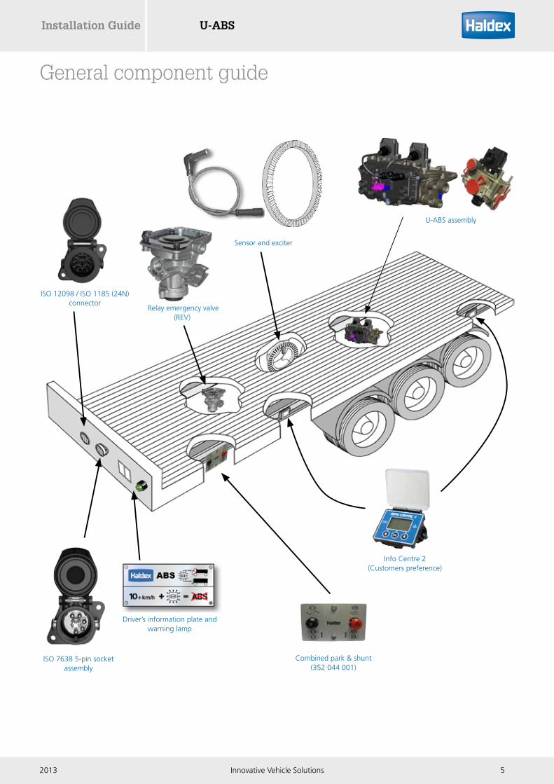
General component guide
Driver’s information plate and warning lamp
U-ABS assembly
Info Centre 2 (Customers preference)
ISO 7638 5-pin socket assembly
Sensor and exciter
Relay emergency valve (REV)
Combined park & shunt (352 044 001)
ISO 12098 / ISO 1185 (24N) connector

U-ABS Installation Guide
6 Innovative Vehicle Solutions 2013
Note:Aux to be set in line with DIAG+
Item Description Notes1 ABS label
2 ISO 7638 5-pin socket assembly
3 ISO 12098 / ISO1185 (24N) Optional safety backup cable
4 Info Centre 2 (via SOV connection)
5 U-ABS ECU assembly
6 Sensor assembly
7 Exciter
8 COLAS® AUX 1
Chassis components
ISO 7638
ISO 12098 / ISO 1185 (24N)
7
6
66
6
1
2
3
8
4
5
7
7 7
Trailer king pin

U-ABSInstallation Guide
72013 Innovative Vehicle Solutions
Dimension and port identification
Port no. Description Notes1 Reservoir port M22 x 1.5 (2 x quantity)
4 Control port M16 x 1.5 (1 x quantity)
21 / 22 Delivery ports M16 x 1.5 (6 x quantity)
278 mm
199
mm
270
mm
(ref
)
256 mm
181
mm
74 m
m
126.75 mm (ref)
2121
211
22
1
4
22
22
Note:No pipe sealant or tape must be used during the installation of U-ABS

U-ABS Installation Guide
8 Innovative Vehicle Solutions 2013
U-ABS versions
Premium
Valve & ECU assembly 364 564 001Premium ECU only 364 569 001
1M, 2M or 3M capable, 4 x sensors and 3 AUX's, with CAN diagnostics.
› For 2S / 1M systems use S1A, S1B and mod 21
› For 2S / 2M systems use S2A, S2B and mod 21 & 22
› For AUX 3 operation, use 23 connector
Standard
Valve & ECU assembly 364 565 001Standard ECU only 364 570 001
1M, 2M capable, 4 x sensors and 1 AUX, with CAN diagnostics.
› For 2S / 1M systems use S1A, S1B and mod 21
› For 2S / 2M systems use S2A, S2B and mod 21 & 22
Basic
Valve & ECU assembly 364 566 001Standard ECU only 364 571 001
2M only capable, 2 x sensors only and no AUX's, without CAN, blink code diagnostics only.
› For 2S / 2M systems use S2A, S2B and mod 21 & 22
› No 1M capability is available
xx
= blanking plug fitted
= option not available (i.e. no pins fitted to case)x
xxxx
x
x

U-ABSInstallation Guide
92013 Innovative Vehicle Solutions
System configurations
Notes:
› Directly controlled axle shall not be lifted
› Any axle without directly controlled wheels may be a lift axle
› Sensor references on an axle may be reversed but the wheel sensor to modulator valve relationship must be maintained
› Any axle may be a command steered axle. Self steer axles are subject to the axle manufacturers recommendations
= connection no. 21 on the U-ABS ECU2
2S / 1M

U-ABS Installation Guide
10 Innovative Vehicle Solutions 2013
2S/2
M
Notes:
› Directly controlled axle shall not be lifted
› Any axle without directly controlled wheels may be a lift axle
› Sensor references on an axle may be reversed but the wheel sensor to modulator valve relationship must be maintained
› Any axle may be a command steered axle. Self steer axles are subject to the axle manufacturers recommendations
2S / 2M

U-ABSInstallation Guide
112013 Innovative Vehicle Solutions
Notes:
› Directly controlled axle shall not be lifted
› Any axle without directly controlled wheels may be a lift axle
› Sensor references on an axle may be reversed but the wheel sensor to modulator valve relationship must be maintained
› Any axle may be a command steered axle. Self steer axles are subject to the axle manufacturers recommendations
2S/2
M2S / 2M

U-ABS Installation Guide
12 Innovative Vehicle Solutions 2013
Notes:
› Either, but not both directly controlled axles may be lifted
› Any axle without directly controlled wheels may be a lift axle
› Sensor references on an axle may be reversed but the wheel sensor to modulator valve relationship must be maintained
› Any axle may be a command steered axle. Self steer axles are subject to the axle manufacturers recommendations
4S/2
M4S / 2M side x side

U-ABSInstallation Guide
132013 Innovative Vehicle Solutions
Notes:
› Directly controlled axles shall not be lifted
› Any axle without directly controlled wheels may be a lift axle.
› Sensor references on an axle may be reversed but the wheel sensor to modulator valve relationship must be maintained
› Any axle may be a command steered axle. Self steer axles are subject to the axle manufacturers recommendations
› Adaptive surface control (ASC) on modulator 22 and select low (SL) on modulator 21
4S/2
M4S / 2M axle x axle
U-ABS Installation Guide
14 Innovative Vehicle Solutions 2013
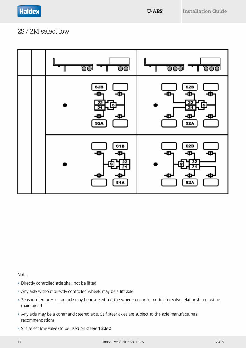
Notes:
› Directly controlled axle shall not be lifted
› Any axle without directly controlled wheels may be a lift axle
› Sensor references on an axle may be reversed but the wheel sensor to modulator valve relationship must be maintained
› Any axle may be a command steered axle. Self steer axles are subject to the axle manufacturers recommendations
› S is select low valve (to be used on steered axles)
2S/2
M2S / 2M select low

U-ABSInstallation Guide
152013 Innovative Vehicle Solutions
Notes:
› Directly controlled axle shall not be lifted
› Any axle without directly controlled wheels may be a lift axle
› Sensor references on an axle may be reversed but the wheel sensor to modulator valve relationship must be maintained
› Any axle may be a command steered axle. Self steer axles are subject to the axle manufacturers recommendations
› S is select low valve (to be used on steered axles)
› R is relay valve (can be used if required to comply with response times)
2S/2
M2S / 2M select low + relay
U-ABS Installation Guide
16 Innovative Vehicle Solutions 2013
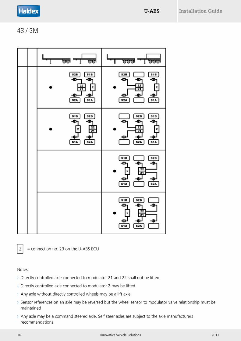
= connection no. 23 on the U-ABS ECU2
Notes:
› Directly controlled axle connected to modulator 21 and 22 shall not be lifted
› Directly controlled axle connected to modulator 2 may be lifted
› Any axle without directly controlled wheels may be a lift axle
› Sensor references on an axle may be reversed but the wheel sensor to modulator valve relationship must be maintained
› Any axle may be a command steered axle. Self steer axles are subject to the axle manufacturers recommendations
4S/3
M4S / 3M

U-ABSInstallation Guide
172013 Innovative Vehicle Solutions
= connection no. 23 on the U-ABS ECU2
Notes:
› Directly controlled axles shall not be lifted
› Any axle without directly controlled wheels may be a lift axle
› Sensor references on an axle may be reversed but the wheel sensor to modulator valve relationship must be maintained
4S/3
M4S / 3M

U-ABS Installation Guide
18 Innovative Vehicle Solutions 2013
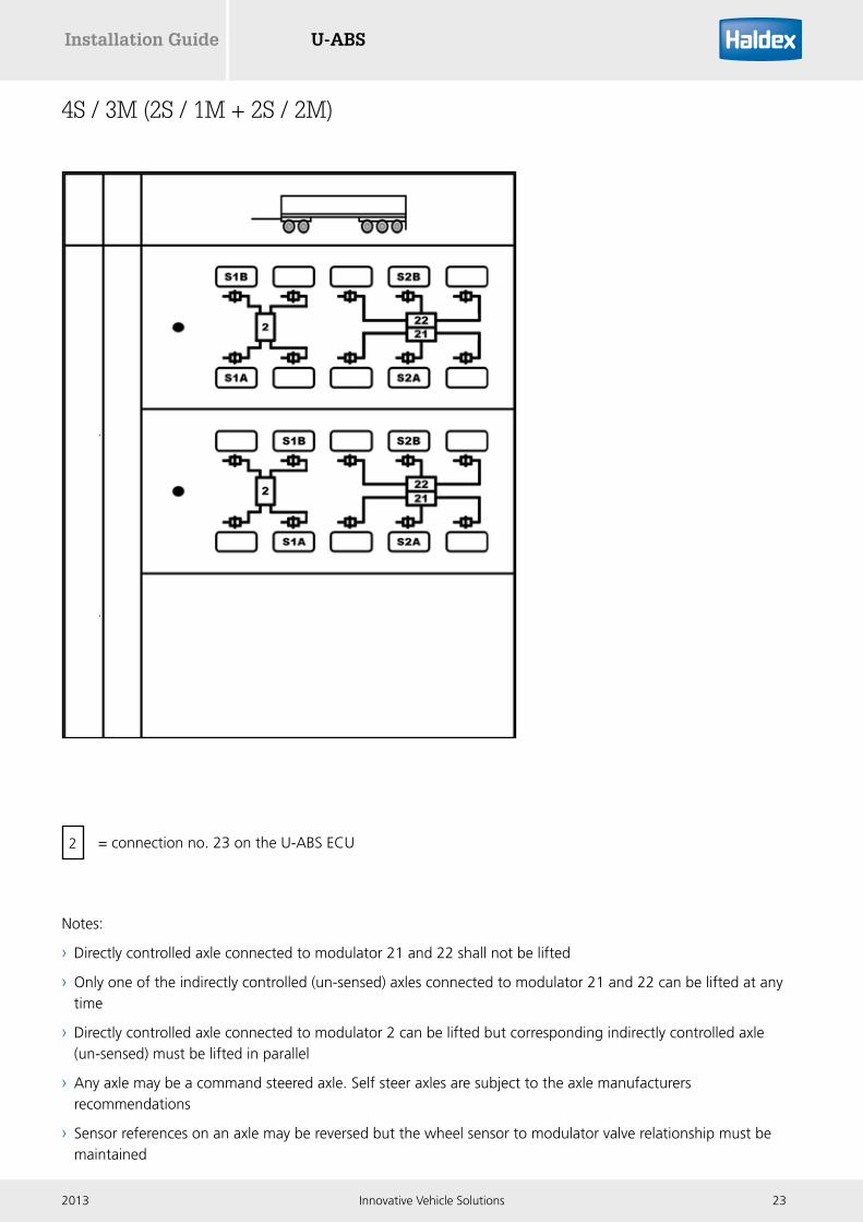
= connection no. 23 on the U-ABS ECU2
Notes:
› Directly controlled axle connected to modulator 21 and 22 shall not be lifted
› Only one of the indirectly controlled (un-sensed) axles connected to modulator 21 and 22 can be lifted at any time
› Directly controlled axle connected to modulator 2 can be lifted but corresponding indirectly controlled axle (un-sensed) must be lifted in parallel
› Any axle may be a command steered axle. Self steer axles are subject to the axle manufacturers recommendations
› Sensor references on an axle may be reversed but the wheel sensor to modulator valve relationship must be maintained
4S/3
M
(2S
/1M
+ 2
S/2M
)S
_3I2
LS
_2L3
I4S / 3M (2S / 1M + 2S / 2M)

U-ABSInstallation Guide
192013 Innovative Vehicle Solutions
= connection no. 23 on the U-ABS ECU2
Notes:
› Directly controlled axle connected to modulator 21 and 22 shall not be lifted
› Both indirectly controlled (un-sensed) axles connected to modulator 21 and 22 can be lifted
› Directly controlled axle connected to modulator 2 can be lifted
› Any axle may be a command steered axle. Self steer axles are subject to the axle manufacturers recommendations
› Sensor references on an axle may be reversed but the wheel sensor to modulator valve relationship must be maintained
4S/3
M
(2S
/1M
+ 2
S/2M
)S
_1L3
I4S / 3M (2S / 1M + 2S / 2M)

U-ABS Installation Guide
20 Innovative Vehicle Solutions 2013
= connection no. 23 on the U-ABS ECU2
Notes:
› Directly controlled axle connected to modulator 21 and 22 shall not be lifted
› Both indirectly controlled (un-sensed) axles connected to modulator 21 and 22 can be lifted
› Directly controlled axle connected to modulator 2 can be lifted
› Any axle may be a command steered axle. Self steer axles are subject to the axle manufacturers recommendations
› Sensor references on an axle may be reversed but the wheel sensor to modulator valve relationship must be maintained
4S/3
M
(2S
/1M
+ 2
S/2M
)S
_3I1
L4S / 3M (2S / 1M + 2S / 2M)

U-ABSInstallation Guide
212013 Innovative Vehicle Solutions
= connection no. 23 on the U-ABS ECU2
Notes:
› Directly controlled axle connected to modulator 21 and 22 shall not be lifted
› Indirectly controlled (un-sensed) axle connected to modulator 21 and 22 can be lifted but only after modulator 2 indirectly controlled (un-sensed) axle is lifte.
› Directly controlled axle connected to modulator 2 can be lifted but corresponding indirectly controlled axle must be lifted in parallel
› Any axle may be a command steered axle. Self steer axles are subject to the axle manufacturers recommendations
› Sensor references on an axle may be reversed but the wheel sensor to modulator valve relationship must be maintained
4S/3
M
(2S
/1M
+ 2
S/2M
)S
_2L2
I4S / 3M (2S / 1M + 2S / 2M)
U-ABS Installation Guide
22 Innovative Vehicle Solutions 2013
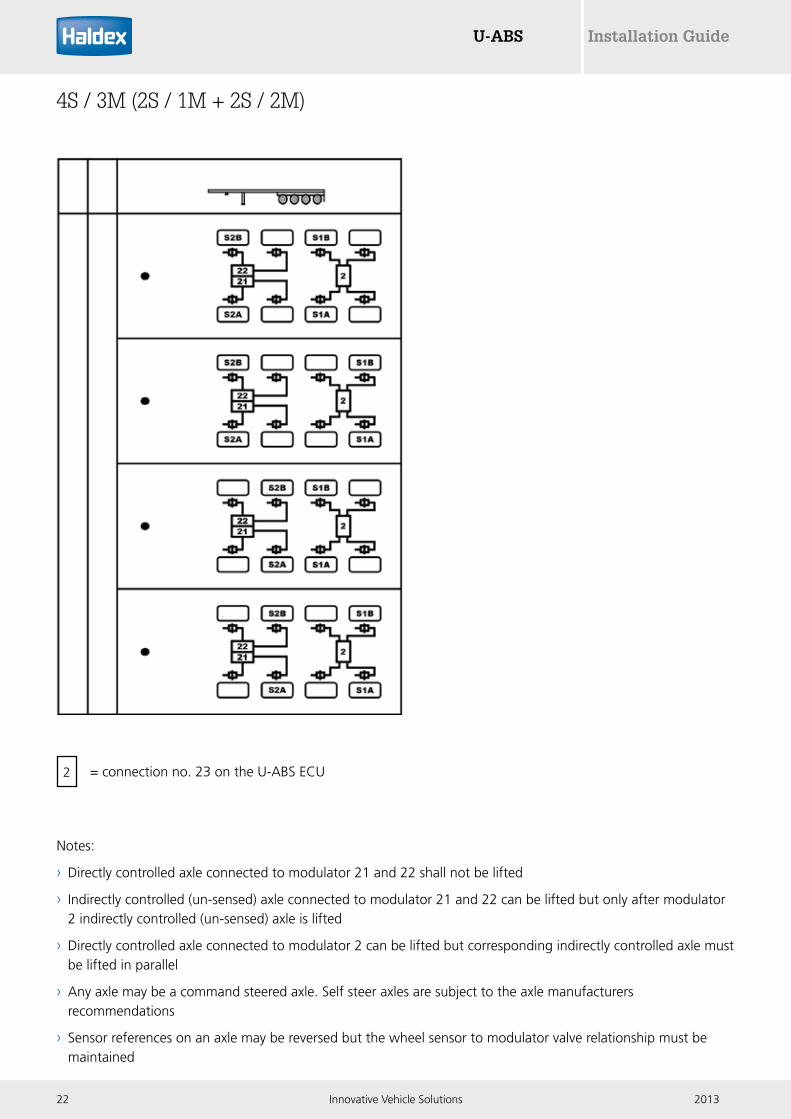
= connection no. 23 on the U-ABS ECU2
Notes:
› Directly controlled axle connected to modulator 21 and 22 shall not be lifted
› Indirectly controlled (un-sensed) axle connected to modulator 21 and 22 can be lifted but only after modulator 2 indirectly controlled (un-sensed) axle is lifted
› Directly controlled axle connected to modulator 2 can be lifted but corresponding indirectly controlled axle must be lifted in parallel
› Any axle may be a command steered axle. Self steer axles are subject to the axle manufacturers recommendations
› Sensor references on an axle may be reversed but the wheel sensor to modulator valve relationship must be maintained
4S/3
M
(2S
/1M
+ 2
S/2M
)S
_2I2
L4S / 3M (2S / 1M + 2S / 2M)
U-ABSInstallation Guide
232013 Innovative Vehicle Solutions
= connection no. 23 on the U-ABS ECU2
Notes:
› Directly controlled axle connected to modulator 21 and 22 shall not be lifted
› Only one of the indirectly controlled (un-sensed) axles connected to modulator 21 and 22 can be lifted at any time
› Directly controlled axle connected to modulator 2 can be lifted but corresponding indirectly controlled axle (un-sensed) must be lifted in parallel
› Any axle may be a command steered axle. Self steer axles are subject to the axle manufacturers recommendations
› Sensor references on an axle may be reversed but the wheel sensor to modulator valve relationship must be maintained
4S/3
M
(2S
/1M
+ 2
S/2M
)F_
2L3I
4S / 3M (2S / 1M + 2S / 2M)

U-ABS Installation Guide
24 Innovative Vehicle Solutions 2013
= connection no. 23 on the U-ABS ECU2
Notes:
› Directly controlled axle connected to modular 21 and 22 shall not be lifted
› Indirectly controlled (un-sensed) axle connected to modulator 21 and 22 can be lifted but only after modulator 2 indirectly controlled axle is lifted
› Directly controlled axle connected to modulator 2 can be lifted but corresponding indirectly controlled axle (un-sensed) must be lifted in parallel
› Any axle may be a command steered axle. Self steer axles are subject to the axle manufacturers recommendations
› Sensor references on an axle may be reversed but the wheel sensor to modulator valve relationship must be maintained
4S/3
M
(2S
/1M
+ 2
S/2M
)F_
2L2I
4S / 3M (2S / 1M + 2S / 2M)
U-ABSInstallation Guide
252013 Innovative Vehicle Solutions
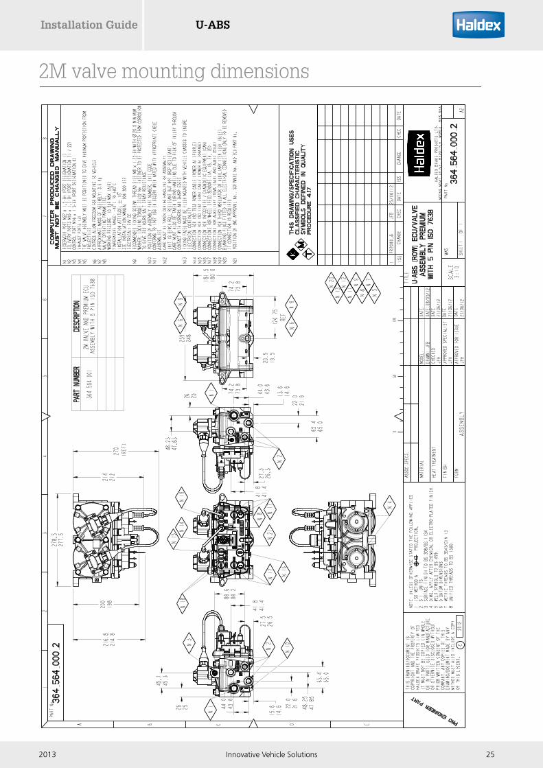
2M valve mounting dimensions

U-ABS Installation Guide
26 Innovative Vehicle Solutions 2013
1M valve mounting dimensions
U-ABSInstallation Guide
272013 Innovative Vehicle Solutions
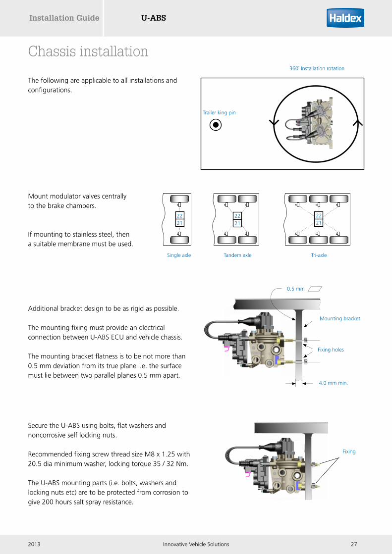
Chassis installation
0.5 mm
4.0 mm min.
Mounting bracket
Fixing holes
The following are applicable to all installations and configurations.
Trailer king pin
360˚ Installation rotation
Additional bracket design to be as rigid as possible.
The mounting fixing must provide an electrical connection between U-ABS ECU and vehicle chassis.
The mounting bracket flatness is to be not more than 0.5 mm deviation from its true plane i.e. the surface must lie between two parallel planes 0.5 mm apart.
Secure the U-ABS using bolts, flat washers and noncorrosive self locking nuts.
Recommended fixing screw thread size M8 x 1.25 with 20.5 dia minimum washer, locking torque 35 / 32 Nm.
The U-ABS mounting parts (i.e. bolts, washers and locking nuts etc) are to be protected from corrosion to give 200 hours salt spray resistance.
Fixing
Single axle Tandem axle Tri-axle
Mount modulator valves centrally to the brake chambers.
If mounting to stainless steel, then a suitable membrane must be used.
2221
2221
2221

U-ABS Installation Guide
28 Innovative Vehicle Solutions 2013
Ground level
Deck of trailer
Modulator connector
Identify orientation of sockets in solenoid connector and push fully connector onto the modulator solenoid pins.
Ensure connectors are fully locked onto the solenoids with a twisting action to activate bayonet fitment.
Care should be taken to provide reasonable access to the ECU / valve for replacement of cables.
D = 150 mm minimum E = 1. Assembly to be above axle centre line. 2. To be as high in the frame as possible.
Check the earth continuity between U-ABS ECU bracket and vehicle chassis.
Electrical resistance (R) to be less than 5 ohms. 0 < R < 5 ohms
Position assembly as high as possible in the chassis to provide as much protection to the assembly from direct spray, other road debris and to achieve an acceptable hose routing.
Pitch angle: assembly must be mounted vertically.
E
D
0 5

U-ABSInstallation Guide
292013 Innovative Vehicle Solutions
ISO 7638 socket assembly
ISO 7638 5-pin (purple ECU connector)
Should be positioned / grouped with other electrical connections.
When installing the ISO 7638 it is important that sufficient extra length of cable is allowed to expose the socket assembly for replacement in service.
It will be necessary to pull the ISO 7638 socket clear from the trailer headboard to undo the gland nut.
ISO 7638ISO 1185 (24N)
Gland nut
Trailer headboard
Approx 350 mm
10 Max 120 Min
45 º
60 M
ax
55 M
in 60 Min 60 Min
80 M
in
50.3
0 48
.70
25.1
5 24
.25
74.90 74.30
37.45 37.15
9.0 8.5
57.0 55.0ø
ø
maxmin
max
min minmin
min
Clearance dimensions Socket mounting dimensions
Pin detail and identification key location.
1 2
3
54
Pin no Description Notes
1 Red (RD) 4 mm2 B+ batt
2 Black (BK) 1.5 mm2 B+ ign
3 Yellow (YE) 1.5 mm2 B- earth
4 Brown (BN) 4 mm2 B- earth
5 White (W) 1.5 mm2 Lamp

U-ABS Installation Guide
30 Innovative Vehicle Solutions 2013
Power (ISO 7638) connector
Ensure contact pins and seal are kept clean and free of any contamination prior to installation.
Unlock the 'Power' (ISO 7638) slide lock housing by pulling down the purple latch.
Lock the 'Power' (ISO 7638) slide lock housing by pushing up the purple latch.
Note:Blanking plug (027514709) and o-ring (024505009) must be fitted to the ISO 7638 connector if no cable is inserted (i.e. U-ABS using only the 24N connector for power).

U-ABSInstallation Guide
312013 Innovative Vehicle Solutions
Purple connector
ConnectionsMake sure that all connections (socket and plug) are clean and dry before assembly.
Trailer chassis
20.0 min dia
Feed all connectors through the chassis with the protective cap in place to avoid connector sockets being contaminated.
Remove protective cap from end of connector before connecting into the ECU.
If required remove the blanking plug (027514709) from the ISO 7638 position.
1
2
3

U-ABS Installation Guide
32 Innovative Vehicle Solutions 2013
L
Purple connector
Identify orientation ‘L’ of the ISO 7638 purple coloured 5-pin connector. Ensure contact pins and seal are clean and free of any contamination prior to installation.
In position Power (ISO 7638), on the slide lock housing, insert connector fully home.
Make sure that the connector is fully inserted into the ECU slide lock housing.
Push in the purple lock slider.
Do not use extreme force to push in slider.
Warning:
› If difficulty is encountered in locking the slider, check plug or connector for correct fitment
› If the white o-ring is visible, the plug is not installed correctly and slider will not lock into position
U-ABSInstallation Guide
332013 Innovative Vehicle Solutions
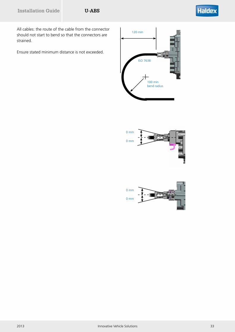
All cables: the route of the cable from the connector should not start to bend so that the connectors are strained.
Ensure stated minimum distance is not exceeded.
100 minbend radius
120 min
ISO 7638
0 mm
0 mm
0 mm
0 mm

U-ABS Installation Guide
34 Innovative Vehicle Solutions 2013
The ISO 7638 cable junction box is used to extend the ISO 7638 power to allow additional U-ABS systems to be connected together (i.e. road trains,multi-axle installations etc).
Part number 364 590 001
Methods of fixing / mounting
The ISO 7638 cable junction box can be mounted using either tie wraps or M6 fasteners.
The unit should be positioned to give maximum protection from projectiles and water ingress.
The M6 fastener should be tightened to 4.5 - 6.1 Nm
The tie wrap should be threaded through the junction box as shown
U-ABS ISO 7638 cable junction box
Note:
› Blanking plug (027514709) and o-ring (024505009) must be fitted to the ISO 7638 connector if no cable is inserted
› The ISO 7638 cable junction box is not to be used to power other auxiliary equipment like telematics systems. Telematics must receive it's power from U-ABS auxiliary outputs. These have voltage and current limit protection to ensure the ABS power supply is protected in case of faults with auxiliary equipment. This is a requirement of the ECE R13 braking regulation

U-ABSInstallation Guide
352013 Innovative Vehicle Solutions

U-ABS Installation Guide
36 Innovative Vehicle Solutions 2013
Pin no Description Notes
1 Red (RD) 4 mm2 B+ batt
2 Black (BK) 1.5 mm2 B+ ign
3 Yellow (YE) 1.5 mm2 B- earth
4 Brown (BN) 4 mm2 B- earth
5 White (W) 1.5 mm2 Lamp
6 White / green (W / GN) 1.5 mm2 CAN hi
7 White / brown (W / BN) 1.5 mm2 CAN lo
Towing vehicle ISO 7638 wiring
ISO 7638 7-pin
1
2
3
4
5
6** CAN - High
7** CAN - LowTruckEBS
Amber(*Red)
Red
Fuse
25/30 A
16 A (*2A)
* ISO7638 - 1996**Not fitted on ISO7638 - 1985
1
2
3
4
5
6** CAN - High
7** CAN - LowTruckEBS
Amber(*Red)
Red
Fuse
25/30 A
16 A (*2A)
* ISO7638 - 1996**Not fitted on ISO7638 - 1985
* ISO 7638 - 1996 ** Not fitted on ISO 7638 - 1995
Lamp indicator
25 / 30 A
16 A (*2A)
6 ** CAN high
5
4
3
2
1
7 ** CAN low
Fuse
Red
Amber (*red)

U-ABSInstallation Guide
372013 Innovative Vehicle Solutions
AB
B
C
Sensor installation
Stripping of axle
See individual axle manufacturers information.Remove hub and drum assembly. Refer to individual ABS axle layout for details of the machine location area ‘A’ on hub ‘B’.
Exciter (solid type)
Available in two sizes to suit differing diameters of wheel. Establish correct exciter teeth in relation to tyre size refer to GS0006.
100 tooth exciter - dynamic effective rolling radius (rdyn) = 442 to 645 mm. 80 tooth exciter - dynamic effective rolling radius (rdyn) = 357 to 522 mm.
Heat exciter uniformly to required temperature.
Fit to hub and ensure that it is fully seated on the location area machined on the hub ‘B’. Dimension ‘C’ to be zero gap 0 to 360 degrees.
U-ABS Installation Guide
38 Innovative Vehicle Solutions 2013
D
E F F
J
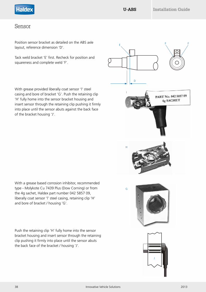
Sensor
Position sensor bracket as detailed on the ABS axle layout, reference dimension ‘D’.
Tack weld bracket ‘E’ first. Recheck for position and squareness and complete weld ‘F’.
With grease provided liberally coat sensor ‘l’ steel casing and bore of bracket ‘G’. Push the retaining clip ‘H’ fully home into the sensor bracket housing and insert sensor through the retaining clip pushing it firmly into place until the sensor abuts against the back face of the bracket housing ‘J’.
With a grease based corrosion inhibitor, recommended type - Molykote Cu 7439 Plus (Dow Corning) or from the 4g sachet, Haldex part number 042 5857 09, liberally coat sensor ‘l’ steel casing, retaining clip ‘H’ and bore of bracket / housing ‘G’.
Push the retaining clip ‘H’ fully home into the sensor bracket housing and insert sensor through the retaining clip pushing it firmly into place until the sensor abuts the back face of the bracket / housing ‘J’.
I
H
G

U-ABSInstallation Guide
392013 Innovative Vehicle Solutions
K
Layout the sensor cable route. Ensure sensor cable is not under tension and not fouling brake shoe. Avoid any sharp edges and moving parts. The cable exit from the brake torque plate or dirt shield should be via a grommet ‘K’.
Reassemble hub assembly
Sensor must be central over the exciter teeth.The gap between exciter ‘M’ and sensor ‘l’ must not exceed N = 0.5 mm.
Maximum run out of 0.2 mm true indicator reading.
Before fitment of hub cap / cover check sensor output.
N
IM

U-ABS Installation Guide
40 Innovative Vehicle Solutions 2013
P
Ø 3.0-2.0 mm
ECU ECU
Locking tag
Sensor and AUX connections
Depending on the U-ABS version, the ECU is supplied with various blanking plugs fitted.
Sensor / AUX / 24N blanking plug
CAN diagnostic blanking plug
These require removing to allow fitment of sensors or permitted auxiliary equipment.
Blanking plugs must remain fitted where no electrical connections are made to the U-ABS (i.e. unused electrical connectors with pins must be blanked off).
U-ABS locking tag positions
With a tool ‘P’ having a flat end of Ø 3-2 mm insert and press in locking tab of plug. While depressed pull out plug from housing.
Identify connector orientation:
› Sensor black body connector
› Auxiliary blue body connector
Ensure contact pins and seal are kept clean and free of any contamination prior to installation. Insert fully home in the ECU’s housing into appropriate marked positions.
ECU
Example: U-ABS Premium version shown

U-ABSInstallation Guide
412013 Innovative Vehicle Solutions
Aux 3 (Premium version only)
For AUX 3 use cable 364 572 xxx (tin plate) and not 814 012 xxx (gold plate) to avoid possibility of pin corrosion.
ECU identification
Tags removed1 2 3 4 A B P 5
Component
S1A Sensor 1A
S1B Sensor 1B
S2A Sensor 2A
S2B Sensor 2B
ECU identification
Tags removed1 2 3 4 A B P 5
Component
AUX 1 COLAS®
Example sensor 1B
Blackfront case
Bluefront case
Example COLAS®
Sensor connector
Identification tags are incorporated on either side of the sensor / ECU connector.These must be removed to identify the appropriate sensor before connecting into the ECU.
Auxiliary connector
Identification tags are incorporated on either side of the auxiliary connector. These must be removed to identify the appropriate usage before connecting into the ECU.

U-ABS Installation Guide
42 Innovative Vehicle Solutions 2013
Sensor connection
Sensor extension cable socket must be pushed fully into sensor cable plug till they clip into place to prevent falling out with axle vibration.
Haldex recommend that all electrical components are greased prior to assembly using the appropriate electrical grease.
Where possible use a clip and bracket to secure sensor cable connection.
The female connector of the sensor cable should always be horizontal or pointing downward to reduce the possibility of water ingress.
Alternatively: sensor cable connection to be positioned on axle or between axle ‘U’ bolts and supported with cable ties with 50 mm of each end.
Extension cable plug Sensor cable socket
Clip to ‘click’
Sensor cable Extension cable
Dirt shield
Connection assembled into clip
and bracket
Dirt shield fixing bolts
Axle
‘U’ bolts
Cable tie
Cable tie
Axle
Connection
Hub and drum / disk assembly

U-ABSInstallation Guide
432013 Innovative Vehicle Solutions
Sensor cable route should follow the centre line or outer radius of pipe or hose.
Tie wraps are not to be over tightened because on brake application rubber hose expands, i.e. tie wrap could damage the hose and sensor cable.
Do not run sensors leads in spiral wrapping on hoses.
Power leads should be secured down the chassis rail in trunking or to piping and should be secured with 300 mm maximum intervals.
All cables should run ‘up to’ ECU connections.
All cables: the route of the cable from the connector should not start to bend so that the connectors are strained.
Ensure stated minimum distance is not exceeded.
100 minbend radius
120 min
ISO 7638
0 mm
0 mm
0 mm
0 mm
300 max
150 max
Deck of trailer
Cable tie
Axle

U-ABS Installation Guide
44 Innovative Vehicle Solutions 2013
Ø150 max 100 min
B
Ø100 min
Sensor 1A
Sensor 1B
Solenoid
Sensor 1A
Sensor 1B
Solenoid
Excess cable
Excess cable must not be allowed to hang free, but must be attached to the chassis to prevent damage due to vibration and abrasion.
Cable lengths less than 1 m to be coiled into loops of 100 mm minimum and 150 mm maximum diameter.
Excess length which will not form a complete loop may be left to hang in partial loops having a cable bend radius of 50 mm minimum.
Cable lengths greater than 1 m to be coiled and then flattened in the centre ‘B’ to produce a ‘dog bone’ shape.The resulting loops at the end must have a minimum bend radius of 50 mm. Cable ties are to be used to fix the cable in the flattened loop shape.
More than one looped cable must not be looped together.
U-ABSInstallation Guide
452013 Innovative Vehicle Solutions
Junction box
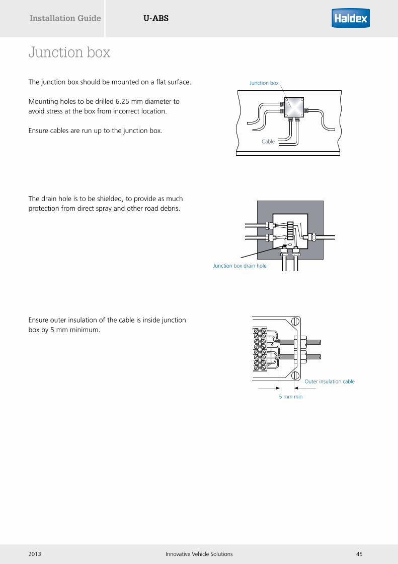
The junction box should be mounted on a flat surface.
Mounting holes to be drilled 6.25 mm diameter to avoid stress at the box from incorrect location.
Ensure cables are run up to the junction box.
The drain hole is to be shielded, to provide as much protection from direct spray and other road debris.
Ensure outer insulation of the cable is inside junction box by 5 mm minimum.
Cable
Junction box
Junction box drain hole
Outer insulation cable
5 mm min

U-ABS Installation Guide
46 Innovative Vehicle Solutions 2013
The trailer warning lamp must be positioned where it can be seen from the drivers rear view mirror.
The warning lamp and wiring should be mounted above the fifth wheel plate.
The warning lamp must not protrude beyond the vehicle width.
The trailer warning lamp indicates the operation of the U-ABS system when only the stop light power is connected (24N).
Instruction label: should be mounted adjacent to the green warning lamp.
Black (-)
Red (+)
Fifth wheel plate
Trailer warning lamp

U-ABSInstallation Guide
472013 Innovative Vehicle Solutions
Clearance and mounting dimensions
Shaded area around hole to be flat and free from raised markings or surface imperfections which may prevent flush fitting of the connector.
Mount the diagnostic connector on the outside of the main chassis rail. The position must be in an accessible area but not in the direct spray of the wheels.
The connector must be mounted horizontally.
Tighten nut ‘R’ to a torque of 3-4 Nm (2-3 Ibft).
Cable to run up to connector and secured to the chassis, or appropriate cable or pipe runs, with cable ties at 300 mm maximum intervals.
Ensure that the cover is fitted and correctly ‘locked’ in place.
Note:For installation of Info Centre 2 refer to instructions leaflet 006 300 000
Side of vehicle connector (SOV)
Ø24 max
Ø50 max
40.0 min
40.0 min
300 max
100 min
R
Alt
120.0 min
65.0 min

U-ABS Installation Guide
48 Innovative Vehicle Solutions 2013
Left side
Right side
Underside
Front face
Painting
Masked areas
In the event of paint or coating work all none used connections, pneumatic ports and exhausts must be protected. These are indicated by the blue shaded areas as shown. Adequate protection should be used to avoid penetration of the paint or coating. All electrical ports to have connectors or blanking plugs installed. Exhaust ports and connectors / locking areas to be masked during painting.
Painting recommendations: water based, baking for 1 hour @ 100oC
Electro static painting: Haldex recommends that the U-ABS assembly is fitted to the trailer after electro static painting.

U-ABSInstallation Guide
492013 Innovative Vehicle Solutions
Configuring U-ABS
Configuring the U-ABS
The U-ABS is configured using DIAG+ V6 software.The software and operators guide can be downloaded from the Findex section of the Haldex website.
To download the software follow:
1. Click on www.haldex.com/findex2. Click on DIAG+3. Click on multi-language version4. Follow installation procedure
DIAG+ V6 document reference 006300019
Monitoring the U-ABS
Once installed and configured the U-ABS status can also be monitored using an Info Centre 2.The Info Centre 2 operator guide can be downloaded from the Findex section of the Haldex website.
To download the Info Centre 2 operators guide follow:
1. Click on www.haldex.com/findex2. Click on documentation3. Enter 'Info Centre 2' into the keyword box4. Press the search button
Info Centre 2 document reference 006 300 001

U-ABS Installation Guide
50 Innovative Vehicle Solutions 2013
CAN diagnostics
Pin 1 B+ DIAGPin 2 ISO 11898 CAN hiPin 3 ISO 11898 CAN loPin 4 B-
The CAN connector is used to connect the U-ABS to an Info Centre 2 or a laptop.
Pin 3
Pin 4Pin 1
Pin 2

U-ABSInstallation Guide
512013 Innovative Vehicle Solutions
Info Centre 2 diagnostic trouble codes (DTC)
Info Centre 2 DTC Possible cause
Wheel sensor 1A or 1B continuity 1A or 1B wheel sensor / wiring open or short circuit
Wheel sensor 2A or 2B continuity 2A or 2B wheel sensor / wiring open or short circuit
Wheel sensor 1A or 1B signal integrity 1A or 1B wheel sensor signal fault
Wheel sensor 2A or 2B signal Integrity 2A or 2B wheel sensor signal fault
Wheel sensor 1A or 1B output level 1A or 1B wheel sensor system fault
Wheel sensor 2A or 2B output level 2A or 2B wheel sensor system fault
EPRV 21 or 22 hold solenoid short circuit Modulator 21 or 22 hold solenoid short circuit
EPRV 21 or 22 dump solenoid short circuit Modulator 21 or 22 dump solenoid short circuit
EPRV 21 or 22 hold solenoid open circuit Modulator 21 or 22 hold solenoid open circuit
EPRV 21 or 22 dump solenoid open circuit Modulator 21 or 22 dump solenoid open circuit
EPRV 21 or 22 hold solenoid short to B+ Modulator 21 or 22 hold sol short circuit energised
EPRV 21 or 22 dump solenoid short to B+ Modulator 21 or 22 dump sol short circuit energised
EPRV 21 or 22 hold solenoid unspecified fault Modulator 21 or 22 hold sol control circuit fault
EPRV 21 or 22 dump solenoid unspecified fault Modulator 21 or 22 dump sol control circuit fault
EPRV 21 or 22 delivery sensor short circuit Modulator 21 or 22 delivery transducer short circuit
EPRV 21 or 22 delivery open circuit Modulator 21 or 22 delivery transducer open circuit
EPRV 21 or 22 slow wheel recovery Modulator 21 or 22 slow recovery of one wheel
Slave valve modulator Hold or dump solenoid open or short cct.
Slave valve cable Link cable open or short circuit
Slave valve slow recovery Slow recovery of one wheel of slave valve
Power ISO 7638 fail Power loss on pin 1 or 2 on ISO 7638
Power low voltage Supply voltage at ECU < 16 V
Power high voltage Supply voltage at the ECU greater than 32 V
Power unspecified fault Internal ECU fault
ECU EEprom error Internal ECU fault
ECU configuration error ECU not programmed
ECU EEprom unspecified error Internal ECU fault
ECU shutdown FET Internal ECU fault
AUX 1 / AUX 2 / AUX 3 Auxiliary system wiring open or short circuit
External TPMS TPMS hardware fault (RCU, WUS etc)

U-ABS Installation Guide
52 Innovative Vehicle Solutions 2013
Item Description Material Size Remark1 Emergency pipe Nylon 8 x 1
10 x 1, 10 x 1.2512 x 1.5
2 Service pipe Nylon 8 x 110 x 1, 10 x 1.2512 x 1.5
3a Reservoir pipe Nylon 8 x 110 x 1, 10 x 1.2512 x 1.5
3b Nylon 15 x 1.515 x 1.5 x 2 qty (prefered)18 x 2
short as possible 1.0 m max.short as possible 4.0 m max.
3c Nylon 12 x 1.5
4a4b4c
Brake deliveryPipe
NylonorRubber hose
12 x 1.5orI.D. 11.0, I.D. 13.0
4a, 4b and 4c to be as short as possible.
5 Emergency pipe Nylon
Rubber hose
8 x 110 x 1.2512 x 1.5I.D. 11.0, I.D 13.0
Piping recommendations
1
2
5
3a
2
4a
4a
4b
4c 5
5
5
5
4b 4c
3b
3b
1
3c
x 2 reservoir tanks
as standard
Note:U-ABS should be supplied with clean / dry air.

U-ABSInstallation Guide
532013 Innovative Vehicle Solutions
Pipe fittings
Avoid elbows as much as possible. If essential, use swept type elbow.
Inside diameter of fitting should be the same as the inside pipe diameter it is serving.
On metric (parallel thread) pipe fitting a backing washer and O-ring should be used.
The use of tape (PTFE) must not be used.
Note:No pipe sealant or tape (PTFE) must be used during the installation of U-ABS. No warranty claims will be accepted on pipe sealant or tape induced faults.
Piping information
› Actual pipe sizes need to be optimized for individual trailer response time requirements
› All pipe and rubber hose to comply to recognized international standards
› Nylon pipe to DIN 73378, rubber hose to SAE 1402
› The referenced sizes are defined as guide lines only
› For optimum performance all pipe lengths should be as short as possible

U-ABS Installation Guide
54 Innovative Vehicle Solutions 2013
Item Description1 Emergency coupling
2 Service coupling
3 Pipe filter
4 Relay emergency valve (REV)
5 Air reservoir (capacity as required)
6 U-ABS
7 Brake chamber
TP Test point
DV Drain valve
Piping layouts
Basic layout (2M)
1
2 34
5
6
7
7 7 7
7 7
3
422 x 3
21 x 31
1
TP
DV
DV
TP
1
4
21
1 2
2
2-1
Emergency
Service
x 2 reservoir tanks
as standard
Note:U-ABS should be supplied with clean / dry air.
U-ABSInstallation Guide
552013 Innovative Vehicle Solutions
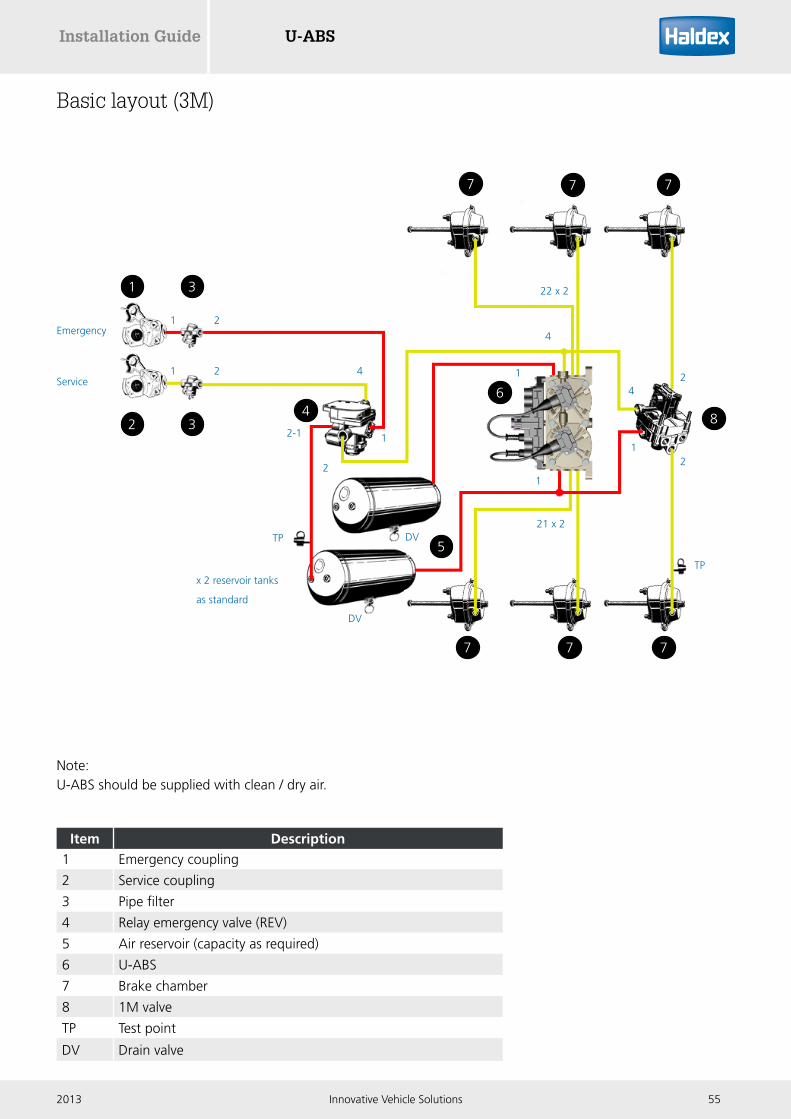
Basic layout (3M)
Item Description1 Emergency coupling
2 Service coupling
3 Pipe filter
4 Relay emergency valve (REV)
5 Air reservoir (capacity as required)
6 U-ABS
7 Brake chamber
8 1M valve
TP Test point
DV Drain valve
1
2 34
5
6
8
7
7 7 7
7 7
3
4
42
2
22 x 2
21 x 2
1
1
1
TP
DV
DV
TP
1
4
21
1 2
2
2-1
Emergency
Service
x 2 reservoir tanks
as standard
Note:U-ABS should be supplied with clean / dry air.

U-ABS Installation Guide
56 Innovative Vehicle Solutions 2013
Item Description1 Emergency coupling
2 Service coupling
3 Pipe filter
4 Relay emergency valve (REV)
5 Air reservoir (capacity as required)
6 U-ABS
7 Spring brake chamber
8 Double check valve (DCV)
9 Quick release valve (QRV)
10 Shunt valve (red button)
11 Park valve (blue or black button)
TP Test point
DV Drain valve
Individual park and shunt valves
1
10 11
3
5
69
777
8
4
7 7 7
32
Service
Emergency
TP TPTP
DV
DV
1 2
1 2
2
1
12 12 2
4
1
4
1
1
11
12 11 12
11
12
22
1 2
12
121112111211
2
11
2
21 x 3
22 x 3
2
2-1
x 2 reservoir tanks
as standard
Note:U-ABS should be supplied with clean / dry air.

U-ABSInstallation Guide
572013 Innovative Vehicle Solutions
Item Description1 Emergency coupling
2 Service coupling
3 Pipe filter
4 Relay emergency valve (REV)
5 Air reservoir (capacity as required)
6 U-ABS
7 Spring brake chamber
8 Double check valve (DCV)
9 Quick release valve (QRV)
10 Combined park and shunt valve (352 044 001)
11 Load sensing valve (LSV, pneumatic version)
TP Test point
DV Drain valve
Combined park and shunt valve including load sensing valve (LSV)
1 3
2 3
5
7 7 7
4
69
777
8
Service
Emergency
1
1 2 4
1 2
TP
TP
1
11 11 11
12
1122 x 3
21 x 3
1
1
1112 11
11
TP
12
TP12
1
22
22
4
1
121212
2
TP
DV
DV
2-1
2
1
21 11
22
10
11
x 2 reservoir tanks
as standard
Note:U-ABS should be supplied with clean / dry air.

U-ABS Installation Guide
58 Innovative Vehicle Solutions 2013
Wiring diagrams
Pin 5
Pin 1
Pin 2
Pin 3
Pin 4
Circuit breaker
Warning lamp
switch
Warning lamp 24V 2.8W
ISO7638ABS
Connector
Pin 4
Pin 1
ISO12098 / ISO1185 (24N)
Connector
ISO7638Switch (B+ Ign)
ISO 7638(B+P)
ISO12098 / ISO1185 (24N)Switch (B+I)
8-32 volts
B+
B-
To ensure correct operation of the ‘Supply switch test box’ the B- connectionmust be connected to the trailer chassis.
+24V
0V
25A Bridge rectifier
3A fuse
110Vor 240V AC
200VA20 sec
4 capacitors10,000 uFeach 40V DCat 2A ripple current
++
A
B
C
D
Connect A to C and B to D for 110V operationConnect B to C for 240V operation
+
-
-
Warning lamp 24 V 2.8 W
Warning lamp switch
ISO 7638 (B+P)
ISO 7638 switch (B+ ign
ISO 7638 ABS connector
ISO 12098 / ISO 1185 (24N) switch (B+I)
Circuit breaker
16 - 32 volts
B+
Pin 5
Pin 1
Pin 2
Pin 3
Pin 4
B-
-
+
ISO 12098 / ISO 1185 (24N)
connector
Pin 4
Pin 1
To ensure correct operation of the ‘supply switch test box’ the B- connection must be connected to the trailer chassis.
Pin 5
Pin 1
Pin 2
Pin 3
Pin 4
Circuit breaker
Warning lamp
switch
Warning lamp 24V 2.8W
ISO7638ABS
Connector
Pin 4
Pin 1
ISO12098 / ISO1185 (24N)
Connector
ISO7638Switch (B+ Ign)
ISO 7638(B+P)
ISO12098 / ISO1185 (24N)Switch (B+I)
8-32 volts
B+
B-
To ensure correct operation of the ‘Supply switch test box’ the B- connectionmust be connected to the trailer chassis.
+24V
0V
25A Bridge rectifier
3A fuse
110Vor 240V AC
200VA20 sec
4 capacitors10,000 uFeach 40V DCat 2A ripple current
++
A
B
C
D
Connect A to C and B to D for 110V operationConnect B to C for 240V operation
+
-
-
3 A fuse 25 A bridge rectifier
4 capacitors 10, 000 uF each 40 V dc at 2 A ripple current
110 V or 240 V ac
A
- +
+
+ 24 V
0 V
B
C
D 200 VA 20 sec
Connect A to C and B to D for 110 V operation Connect B to C for 240 V operation
Supply switch test box circuit diagram
Mains power supply circuit diagram

U-ABSInstallation Guide
592013 Innovative Vehicle Solutions
Basic version

U-ABS Installation Guide
60 Innovative Vehicle Solutions 2013
Standard version
U-ABSInstallation Guide
612013 Innovative Vehicle Solutions
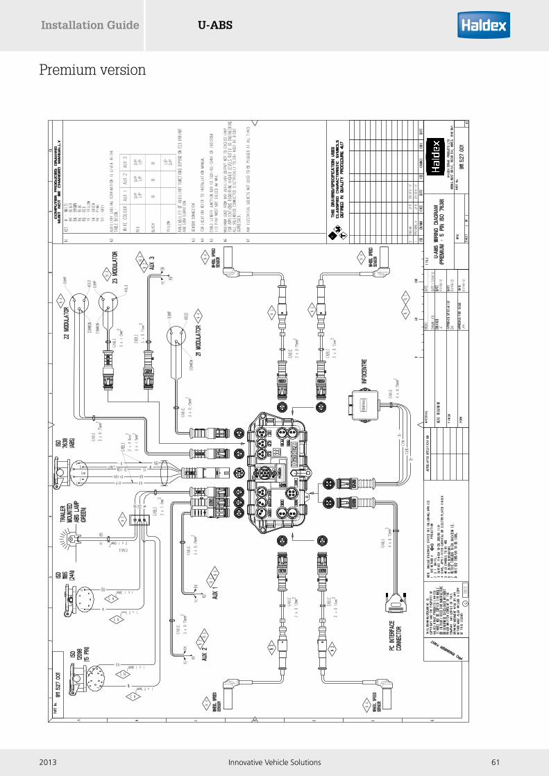
Premium version

U-ABS Installation Guide
62 Innovative Vehicle Solutions 2013
Checking position Measure between Correct value Remarks Figure
Sensor output A B 0.2 V ac minSensor 1A, 1B, 2A, 2B, sensor disconnected from ECU and wheel rotated at 1 rev / 2 sec
1
Sensor resistance A B 1.0< R < 2.4 KΩSensor 1A,1B, 2A, 2BSensor disconnected from ECU
1
Modulator solenoid resistance
B- DS 12 < R < 20 ΩModulator cable disconnected from ECU
2
Modulator solenoid resistance
B- HS 12 < R < 20 ΩModulator cable disconnected from ECU
2
Diagnostic supply using ISO 7638 power
1 4 16 < V < 32 voltsIgnition 'On', approx battery voltage
3
Diagnostic supply using ISO 12098 / 1185 (24N) power
1 4 16 < V < 32 voltsBrake applied, ignition 'On',approx. battery voltage
3
Earth continuityECU / modulator bracket and vehicle chassis
0 < R < 5 Ω 4
COLAS® solenoid resistance
+ - 180 < R < 215 Ω Cable disconnected 5
Electrical testing
0 5
Figure 3
Figure 4
BLA
CK
(-)
RED
(+)
Figure 5
Figure 2
B- HS
DS
B
A
Figure 1
Pin 3
Pin 4Pin 1
Pin 2
U-ABSInstallation Guide
632013 Innovative Vehicle Solutions
U-ABS trailer lamp blink code mode diagnostics
General
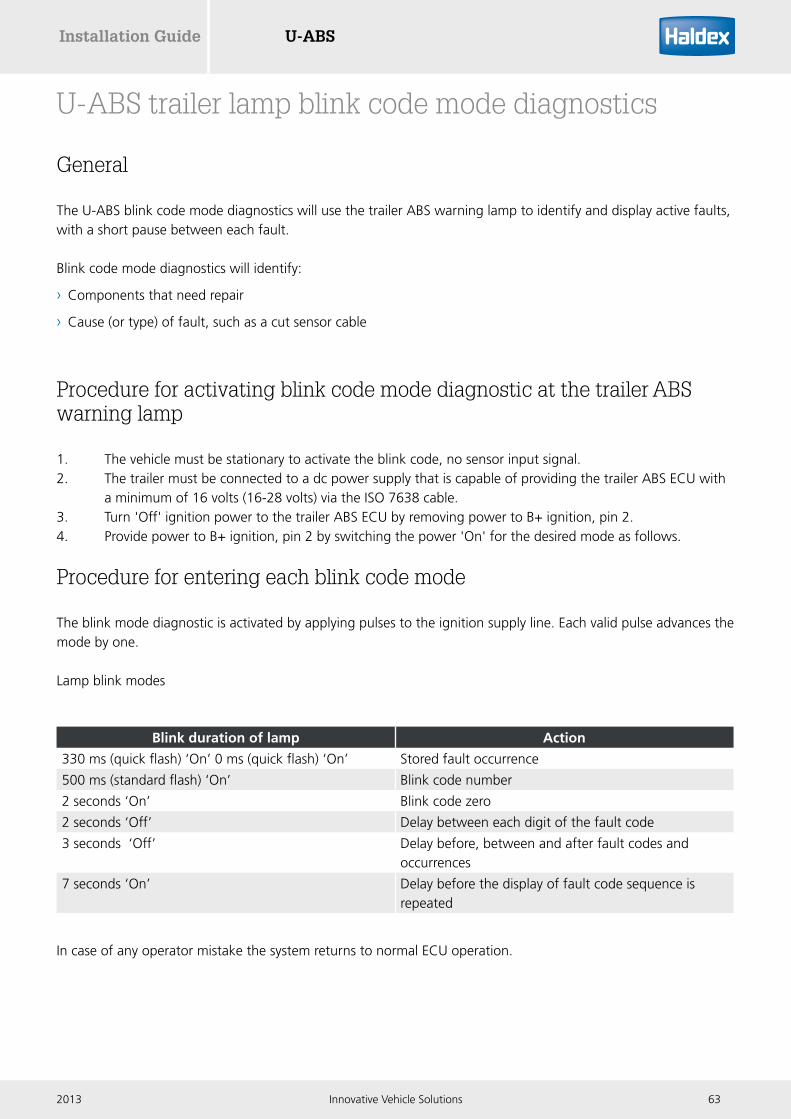
The U-ABS blink code mode diagnostics will use the trailer ABS warning lamp to identify and display active faults, with a short pause between each fault.
Blink code mode diagnostics will identify:
› Components that need repair
› Cause (or type) of fault, such as a cut sensor cable
Procedure for activating blink code mode diagnostic at the trailer ABS warning lamp
1. The vehicle must be stationary to activate the blink code, no sensor input signal.2. The trailer must be connected to a dc power supply that is capable of providing the trailer ABS ECU with a minimum of 16 volts (16-28 volts) via the ISO 7638 cable.3. Turn 'Off' ignition power to the trailer ABS ECU by removing power to B+ ignition, pin 2.4. Provide power to B+ ignition, pin 2 by switching the power 'On' for the desired mode as follows.
Procedure for entering each blink code mode
The blink mode diagnostic is activated by applying pulses to the ignition supply line. Each valid pulse advances the mode by one.
Lamp blink modes
In case of any operator mistake the system returns to normal ECU operation.
Blink duration of lamp Action
330 ms (quick flash) ‘On’ 0 ms (quick flash) ‘On’ Stored fault occurrence
500 ms (standard flash) ‘On’ Blink code number
2 seconds ‘On’ Blink code zero
2 seconds ‘Off’ Delay between each digit of the fault code
3 seconds ‘Off’ Delay before, between and after fault codes and occurrences
7 seconds ‘On’ Delay before the display of fault code sequence is repeated

U-ABS Installation Guide
64 Innovative Vehicle Solutions 2013
There are 3 modes of operation:
1 Normal ECU operating mode 2 Simple mode & wheel speed mode 3 Active faults mode
Once entered, a mode can only be terminated by completely disconnecting all power sources from the ECU. All modes repeat endlessly. Each repeat is separated by 7 seconds of permanent lamp energization. All data elements within a particular emission are separated by 3 seconds of lamp 'Off'.
Normal mode (ignition switched ‘On’)
This is the mode for normal ABS ECU operation. Figure 1 & 2 below are examples of the trailer ABS warning lamp flash sequence in normal mode.
Normal mode ABS operation, no faults
Figure 1
Normal mode ABS operation, with faults
Figure 2
Standard mode
On
Lamp
Off
2.5 Sec
Ignition key power 'On' ECU activated
Standard mode
On
Lamp
Off
Continuous
Ignition key power 'On' ECU activated

U-ABSInstallation Guide
652013 Innovative Vehicle Solutions
Simple mode
In simple mode the trailer ABS warning lamp displays a numerical fault code sequence for each active fault, up to three codes at a time, where the highest level fault code is displayed first. When there is more than one existing fault, the ECU will display the three highest existing faults, from which the ABS must be powered down and repaired before simple mode diagnostics will display additional active faults. Simple mode diagnostics only identifies the component that needs repair; for fault examples see table below.
Item Flash count
System OK Lamp stays 'On'
Sensor 1A 1 Flash
Sensor 1B 2 Flashes
Sensor 2A 3 Flashes
Sensor 2B 4 Flashes
Valve 2.1 7 Flashes
Valve 2.2 8 Flashes
Valve 2.3 9 Flashes
Low voltage 10 Flashes
ECU failure or configuration error
11 Flashes
To activate the simple fault mode the following steps will need to be performed:
› Provide power to B+ ignition, pin 2 for 1 second (+/- ½ second)
› Turn power 'Off' to B+ ignition, pin 2 for 1 second (+/- ½ second)
› Turn power back 'On' to B+ ignition, pin 2
Upon entering simple mode there will be a 3 seconds lamp 'Off' delay before and after active faults are displayed. There will also be a 3 seconds lamp 'Off' delay between active faults when there is more than one active fault. There will be a 7 seconds lamp 'On' delay before the active faults are repeated. Active fault mode diagnostics can be restarted at any time by turning 'Off' power to the ABS ECU and repeating the activation sequence described above. The trailer ABS warning lamp will come 'On' and stay 'On' if the system is OK and there are no active faults.

U-ABS Installation Guide
66 Innovative Vehicle Solutions 2013
Simple mode diagnostics, wheel speed sensor S2B fault
Figure 3 shows the lamp sequence for activating “simple mode” to display a sensor S2B fault, with a 3 seconds lamp 'Off' delay before and after displaying the active fault, and a 7 seconds lamp 'On' delay before repeating the fault.
Figure 3
Simple mode diagnostics, system OK
When the ECU has no active faults the lamp will remain 'On' continuously.Figure 4 shows the lamp sequence for activating “simple mode” to display system 'OK', with a 3 seconds lamp 'Off' delay followed by the display of system 'OK' with the lamp 'On' continuously until ignition power is turned 'Off'.
Figure 4
Simple mode
On
On
On 1 S
1 S
1 S
3 S
1 S 1 S 0.5 S
0.5 S 0.5 S 0.5 S 0.5 S
3 S
3 S 3 S
0.5 S
0.5 S 0.5 S 0.5 S
0.5 S 0.5 S 3 S
0.5 S 0.5 S 0.5 S7 second start 7 S
7 second stop
1 S
Key power 'On' ECU activated
Key power 'On' ECU activated
Key power 'On' ECU activated
Lamp'On' continuous
Key power 'On' ECU activated
Off
Off
Off
Simple mode
Lamp
Lamp
Lamp

U-ABSInstallation Guide
672013 Innovative Vehicle Solutions
Simple mode diagnostics, modulator 2.3 & sensor S2B
Figure 5 shows the lamp sequence for activating “simple mode” to display a modulator 2.3 and sensor S2B faults, with a 3 seconds lamp 'Off' delay before, between and after the active faults, and a 7 seconds lamp 'On' delay before the display of active faults is repeated.
Figure 5
Wheel speed mode
Wheel speed mode is accessible only when in simple mode. This mode emits a blink code for each wheel speed sensor signal received. The ECU will only enter wheel speed mode upon receiving a signal from a wheel speed sensor located at a spinning wheel. The trailer ABS warning lamp will emit the wheel speed blink code 0.5 seconds 'On' and 0.5 seconds 'Off' for the sensed spinning wheel. The ECU will remain in wheel speed mode as long as the wheel remains spinning and a signal is received at the ECU. The ECU will apply reverse lamp 'On' logic when in wheel speed mode, so the lamp will be 'On' for 3 seconds before and after wheel speed blink codes are repeated. The blink codes for the sensed wheels are as follows.
Sensor Flash count
S1A 1 Flash
S1B 2 Flashes
S2A 3 Flashes
S2B 4 Flashes
Key power 'On' ECU activated
Repeats
On
On
On
Off
Off
Off
1 S 1 S 0.5 S
0.5 S
0.5 S 0.5 S 0.5 S 0.5 S 0.5 S 0.5 S 0.5 S 0.5 S 0.5 S
0.5 S 0.5 S 0.5 S
0.5 S
0.5 S
0.5 S
0.5 S 0.5 S 0.5 S 0.5 S 0.5 S 0.5 S 0.5 S 0.5 S Continues
0.5 S 0.5 S 3 S
7 S
0.5 S 0.5 S 0.5 S 0.5 S 0.5 S 0.5 S 0.5 S
0.5 S 0.5 S 0.5 S 0.5 S 0.5 S 0.5 S 0.5 S
3 S
3 S
3 S
1 S
Key power 'On' ECU activated
Simple mode
Lamp
Lamp
Lamp

U-ABS Installation Guide
68 Innovative Vehicle Solutions 2013
Wheel speed mode, sensor S2A fault, simple mode diagnostics then sensor S2A
Figure 6 below shows the ECU’s transition from simple mode with a sensor S2A fault to wheel speed mode upon receiving a signal from sensor S2A located at the spinning wheel and demonstrates how reverse lamp 'On' logic is used to indicate wheel speed mode.
Figure 6
Wheel speed mode, system OK, simple mode diagnostics then sensor S2A
Figure 7 shows the ECU’s transition from simple mode to wheel speed mode when there are no active faults.
Figure 7
Simple mode
Simple mode
Wheel speed mode
Wheel speed mode
Lamp "On" continuous
Key power 'On' ECU activated
Key power 'On' ECU activated
Key power 'On' ECU activated
Key power 'On' ECU activated
On
On
On
On
Off
Off
Off
Off
3 S 0.5 S
0.5 S 0.5 S 0.5 S
0.5 S 0.5 S 0.5 S
0.5 S 0.5 S 0.5 S
0.5 S 0.5 S
0.5 S 0.5 S
0.5 S 0.5 S 0.5 S
0.5 S 0.5 S 0.5 S
Wheel 2A rotating
Wheel 2A rotating Wheel 2A rotating
Wheel 2A rotating
Wheel 2A rotatingRepeats
Wheel 2A rotating
Repeats
0.5 S 0.5 S
1 S
1 S
1 S
1 S
1 S
1 S
?S0.5 S
0.5 S
0.5 S 0.5 S 3 S 0.5 S 0.5 S 3 S3 S (cont)
0.5 S 0.5 S 0.5 S 3 S3 S3 S (cont)
3 S
0.5 S 0.5 S 0.5 S 0.5 S

U-ABSInstallation Guide
692013 Innovative Vehicle Solutions
Active fault mode
In active fault mode the trailer ABS warning lamp displays a numerical fault code sequence for each existing fault, up to three codes at a time where the highest level fault code is displayed first. When there are more than one active fault, the lamp will display the three highest active faults, from which the ABS must be powered down and repaired before additional active faults can be displayed . The blink codes used in the active fault mode are related to the Haldex standard fault codes and are shown in the table below. Each blink code digit will refer to a digit in the Haldex standard fault codes and there will be a 2 seconds lamp 'Off' delay between the 2 digits. There will also be a 3 seconds lamp 'Off' delay before and after displaying the code count, and a 7 seconds lamp 'On' delay before repeating the codes. Not all the Haldex standard fault codes are supported by an equivalent blink code digit.
Code 1st Blinks 2nd Blinks Code definition
00 N / A N / A Normal running (no faults stored).
01 2 sec 1 Wheel speed sensor wiring S1A has an open or short circuit.
02 2 sec 2 Wheel speed sensor wiring S1B has an open or short circuit.
03 2 sec 3 Wheel speed sensor wiring S2A has an open or short circuit.
04 2 sec 4 Wheel speed sensor wiring S2B has an open or short circuit.
07 On On System is OK, no sensor output (vehicle at rest).
Low sensor output
11 1 1 Wheel speed sensor S1A gap too large.
12 1 2 Wheel speed sensor S1B gap too large.
13 1 3 Wheel speed sensor S2A gap too large.
14 1 4 Wheel speed sensor S2B gap too large.
Intermittent low sensor output
20 N / A N / A Incorrect exciter type, incorrect exciter tooth count.
21 2 1 Wheel speed sensor S1A has an erratic output voltage.
22 2 2 Wheel speed sensor S1B has an erratic output voltage.
23 2 3 Wheel speed sensor S2A has an erratic output voltage.
24 2 4 Wheel speed sensor S2B has an erratic output voltage.
One wheel with slow recovery
41 4 1 Slow wheel recovery, on valve 2.1
42 4 2 Slow wheel recovery, on valve 2.2
43 4 3 Slow wheel recovery, on valve 2.3

U-ABS Installation Guide
70 Innovative Vehicle Solutions 2013
Code 1st Blink 2nd Blink Code definition
Open circuit modulator solenoid or solenoid wiring
61 6 1 Hold solenoid open circuit on valve 2.1
62 6 2 Hold solenoid open circuit on valve 2.2
63 6 3 Hold solenoid open circuit on valve 2.3 **
67 6 7 Dump solenoid open circuit on valve 2.1
68 6 8 Dump solenoid open circuit on valve 2.2
69 6 9 Dump solenoid open circuit on valve 2.3 **
Short circuit across modulator solenoid or solenoid wiring group
71 7 1 Hold solenoid short circuit to ground on valve 2.1
72 7 2 Hold solenoid short circuit to ground on valve 2.2
73 7 3 Hold solenoid short circuit to ground on valve 2.3 **
77 7 7 Dump solenoid short circuit to ground on valve 2.1
78 7 8 Dump solenoid short circuit to ground on valve 2.2
79 7 9 Dump solenoid short circuit to ground on valve 2.3 **
Modulator solenoid wiring or solenoid short to B+
80 8 2 sec Output leakage / poor insulation on any of the valve channels.
81 8 1 Hold solenoid short circuit to B+ on valve 2.1
82 8 2 Hold solenoid short circuit to B+ on valve 2.2
83 8 3 Hold solenoid short circuit to B+ on valve 2.3 **
87 8 7 Dump solenoid short circuit to B+ on valve 2.1
88 8 8 Dump solenoid short circuit to B+ on valve 2.2
89 8 9 Dump solenoid short circuit to B+ on valve 2.3 **
Supply voltage
90 9 2 sec Low supply voltage at ECU when solenoid is energized.
91 9 1 No internal ABS ECU solenoid voltage available.
92 9 2 Supply voltage at the controller greater than 32 V.
93 9 3 Short circuit on ABS ECU internal relay.
99 9 9 Checksum fault on ABS ECU.
** = Flash blink codes not implemented
To activate the active fault mode the following steps will need to be performed:
› Provide power to B+ ignition, pin 2 for 1 second (+/- ½ second)
› Turn power 'Off' to B+ ignition, pin 2 for 1 second (+/- ½ second)
› Provide power to B+ ignition, pin 2 for a second time for 1 second (+/- ½ second)
› Turn power 'Off' to B+ ignition, pin 2 for 1 second (+/- ½ second)
› Turn power back 'On' to B+ ignition, pin 2
Active fault mode diagnostics can be restarted at any time by turning 'Off' power to the ABS ECU and repeating the activation sequence described above. The trailer ABS warning lamp will come 'On' and stay 'On' if the system is OK and there are no active faults.

U-ABSInstallation Guide
712013 Innovative Vehicle Solutions
Active fault mode
Key power 'On' ECU activated
Key power 'On' ECU activated
Key power 'On' ECU activated
On
On
Off
Off
3 S
3 S
2 S 2 S 0.5 S 0.5 S 0.5 S
Zero
Repeats
1 S
7 S
1 S 1 S
1 S 1 S
0.5 S 0.5 S
Four
0.5 S 0.5 S
Lamp
Lamp
Active fault mode
Key power 'On' ECU activated
Key power 'On' ECU activated
Key power 'On' ECU activated
On
On
On
Off
Off
Off
3 S
3 S
0.5 S
0.5 S
3 S (cont)
0.5 S 0.5 S 0.5 S
0.5 S 0.5 S 2 S
2 S
2 S
0.5 S
Repeats
1 S 1 S 1 S 0.5S
0.5S
7 S
0.5 S 0.5 S 0.5 S 0.5 S
Zero
0.5S
Four
Three Four
0.5S 0.5S 0.5S
1 S 1 S
Wheel speed sensor wiring S2B has an open or short circuit code 04
Figure 8 shows the lamp sequence for activating “active fault mode” to display a sensor S2B code 04. It also demonstrates a 3 seconds lamp 'Off' delay before and after displaying the active fault, and a 7 seconds lamp 'On' delay before repeating the fault.
Figure 8
Modulator 2.3 code 43 and sensor S2B code 04
Figure 9 shows the lamp sequence for activating “active fault mode” to display a modulator 2.3 code 43 and sensor S2B code 04 with a 2 seconds lamp 'Off' delay between each digit of the fault code, a 3 seconds lamp 'Off' delay before and after the active faults, and a 7 seconds lamp 'On' delay before the display of active faults is repeated.
Figure 9

U-ABS Installation Guide
72 Innovative Vehicle Solutions 2013
System OK, active fault mode, code 07
Figure 10 shows the lamp sequence for activating “active fault mode” to display system “OK”, with a 3 seconds lamp 'Off' delay followed by the display of system “OK” with the lamp 'On' continuously until ignition power is turned 'Off'. When the ECU has no active faults the lamp will remain 'On' continuously until key power is turned 'Off'.
Figure 10
Key power 'On' ECU activated
Key power 'On' ECU activated
Key power 'On' ECU activated
On
Off
Simple mode
1 S 1 S 1 S Lamp "On" continuous
3 S1 S 1 S
Lamp

U-ABSInstallation Guide
732013 Innovative Vehicle Solutions
Time or milage (which ever occurs first)
Components Operation
When hubs are removedExciter
Sensor
Check for damage.
Check for wear, clean and readjust.
Every 3 monthsor 25,000 miles (40,000 Km)
Complete system Perform system checkout and air leakage check.
Annuallyor every 100,000 miles (160,000 Km)
Complete system
Sensor
Perform system check out and air leakage check. Check wiring and piping security and integrity.
Check for wear, clean and readjust.
Recommended maintenance schedule

U-ABS Installation Guide
74 Innovative Vehicle Solutions 2013
U-ABS aftermarket service kits
ECU replacement
These kits are to be used for replacing the U-ABS ECU only, and reusing the original valve assembly.
Description Part number
Premium ECU (364569001) replacement 950 364 824
Standard ECU (364570001) replacement 950 364 825
Basic ECU (364571001) replacement 950 364 826
1M valve replacement
This kit is to be used for replacing the 1M valve body only, and reusing the original solenoid.
Description Part number
1M, 2 port valve only replacement 950 364 822
1M, 6 port valve only replacement 950 364 823
Description Part number
2M valve only replacement 950 364 821
2M valve replacement
This kit is to be used for replacing the 2M valve body only, and reusing the original solenoid.
Description Part number
Solenoid only replacement 950 364 820
Solenoid replacement
This kit is to be used for replacing the solenoid on the 2M and 1M valve, and reusing the original valve assembly.

U-ABSInstallation Guide
752013 Innovative Vehicle Solutions
Part reference
These available service parts can be obtained from Haldex service centres or distributors.
U-ABS assemblies Part number
Premium (1M, 2M, 3M capable, 3 AUX) 364 564 001
Premium ECU only 364 569 001
Standard (1M, 2M capable, 1 AUX) 364 565 001
Standard ECU only 364 570 001
Basic (2S / 2M only capable, no AUX) 364 566 001
Basic ECU only 364 571 001
1M valve assemblies Part number
2 delivery ports, metric threads with DIN connector 364 105 121
6 delivery ports, metric threads with DIN connector 364 115 121
1M valve mounting bracket 015 502 909
Info Centre 2 Part number
Haldex Info Centre 2 815 041 001
Haldex Info Centre 2 ADR 815 046 001
ABS label Part number
Warning label U-ABS 028 539 109
Instruction label 028 525 709M
Identification label 028 506 809
Diagnostic connector label 028 518 909
Sensor kit Part number
Angled (inc. retaining clip) 950 364 503
Straight (inc. retaining clip) 950 364 506
ISO 7638 socket kit Part number
Black cover - no fuse, crimp pins 950 364 402

U-ABS Installation Guide
76 Innovative Vehicle Solutions 2013
Warning lamp Part number
Green warning lamp 950 364 710
Bulb (24 V - 5 W) double pole 950 364 711
U-ABS DIAG+ cable kit Part number
950 800 912
Kit contents:
ECU / pc interface cable (6.5 m) 814 036 001
EB+ ISO diagnostic cable 815 018 001
EB+ SOV / pc interface cable (6.5 m) 814 011 001
Transit case 042 623 719
U-ABS DIAG+ interface kit Part number
950 800 909
Kit contents:
USB pc interface (DIAG+) 815 023 001
USB cable 042 707 309
Park & shunt Part number
Combined park & shunt 352 044 001
TPMS Part number
Receiver control unit (RCU) 815 052 001
Wheel unit sensor (WUS) 042 727 209
Cable / clamp assembly 003 951 709
Cable stretcher tool 042 727 309
Wheel unit sensor indicator label 006 700 021_M
TPMS trigger (hand unit) 815 053 001
U-ABSInstallation Guide
772013 Innovative Vehicle Solutions
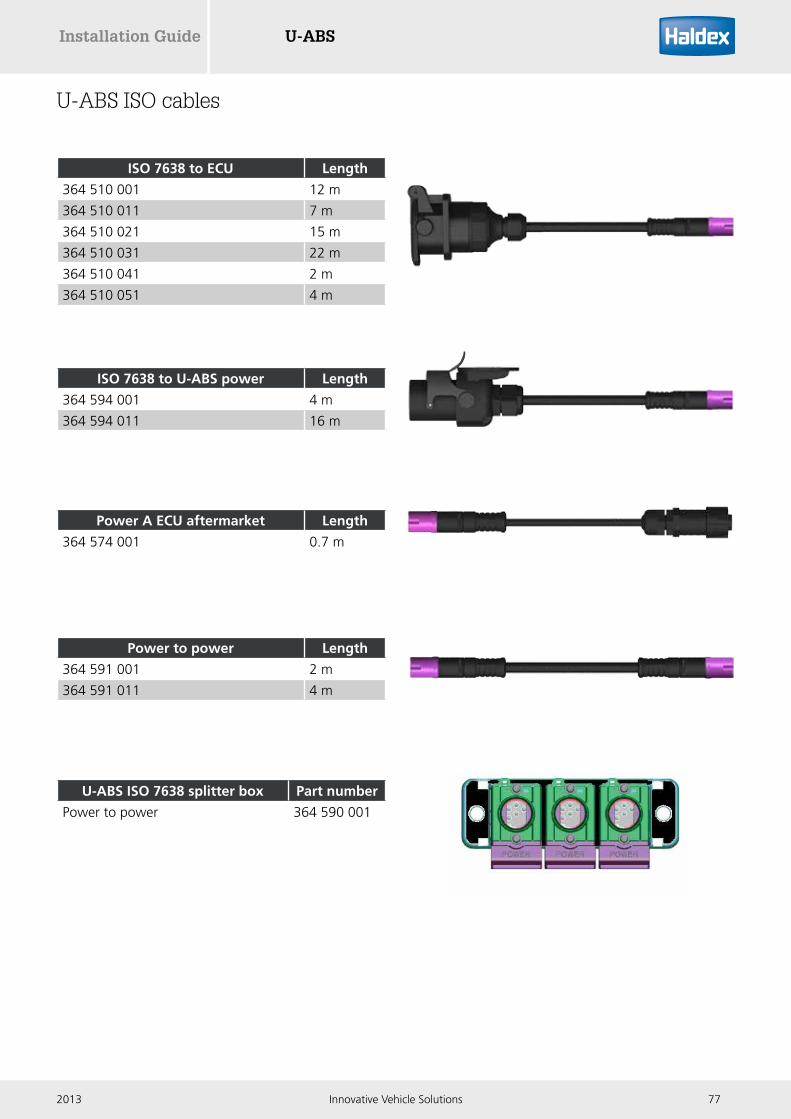
U-ABS ISO cables
ISO 7638 to ECU Length
364 510 001 12 m
364 510 011 7 m
364 510 021 15 m
364 510 031 22 m
364 510 041 2 m
364 510 051 4 m
ISO 7638 to U-ABS power Length
364 594 001 4 m
364 594 011 16 m
Power to power Length
364 591 001 2 m
364 591 011 4 m
U-ABS ISO 7638 splitter box Part number
Power to power 364 590 001
Power A ECU aftermarket Length
364 574 001 0.7 m

U-ABS Installation Guide
78 Innovative Vehicle Solutions 2013
Power B Length
364 509 001 12 m
364 509 011 18 m
U-ABS 24N cables
U-ABS solenoid cables
24N to DIN Length
364 588 001 2 m
364 588 011 4 m
24N ECU aftermarket Length
364 575 001 0.8 m
2M solenoid (0.75 mm2) Length
364 572 001 0.275 m
AUX 3 (Premium version only)
For AUX 3 use cable 364 572 xxx (tin plate) and not 814 012 xxx (gold plate) to avoid possibility of pin corrosion.
3M solenoid (1.5 mm2) Length
364 572 011 3 m
364 572 021 4 m
364 572 031 6 m
364 572 041 8 m
364 572 051 10 m
364 572 061 14 m

U-ABSInstallation Guide
792013 Innovative Vehicle Solutions
U-ABS auxiliary cables
L1
L2
Auxiliary cable Length
814 001 302 7 m
814 001 312 18 m
814 001 322 2 m
814 001 332 4 m
814 001 342 1 m
814 001 352 12 m
814 001 372 10 m
Auxiliary cable to DIN connector Length
814 012 201 7 m
814 012 211 18 m
814 012 221 1 m
814 012 231 2 m
814 012 241 5 m
814 012 251 3 m
814 012 261 4 m
814 012 271 10 m
Male to female to female (2x2x2 way)
L1 L2
814 027 001 0.5 m 0.5 m
Auxiliary (3 pole) to auxiliary (3 pole) Length
814 032 001 1 m
814 032 011 4 m
814 032 021 7 m
814 032 031 18 m
Y-splitter 3x3x3 way Length
814 039 101 0.5 m

U-ABS Installation Guide
80 Innovative Vehicle Solutions 2013
U-ABS diagnostic cables
Info Centre 2 to side of vehicle Length
814 025 001 1 m
Side of vehicle (SOV) to ECU Length
814 030 001 6.5 m
814 030 011 2.5 m
814 030 021 5 m
814 030 031 15 m
Vehicle to pc interface (dongle) Length
814 011 001 6.5 m
814 011 011 15 m
DIAG to DIN Length
814 033 001 1 m
814 033 011 12 m
DIAG to pc interface (dongle) Length
814 036 001 6.5 m
814 036 011 15 m
814 036 021 20 m
DIAG to DIAG Length
814 037 001 6.5 m
814 037 011 0.5 m
814 037 021 8 m
814 037 031 14 m

U-ABSInstallation Guide
812013 Innovative Vehicle Solutions
DIAG to female FCI connector Length
814 040 001 (rear RCU unterminated) 1.2 m
814 040 101 (front RCU unterminated) 1.2 m
814 040 201 (front RCU terminated) 1.2 m
814 040 211 (front RCU terminated) 6 m
814 040 221 (front RCU terminated) 10 m
Y-splitter 4x4x4 way Length
814 038 001 0.5 m
U-ABS sensor cable
Sensor Length
814 004 401 3 m
814 004 411 6 m
814 004 421 2 m
814 004 431 10 m
814 004 441 14 m
814 004 451 8 m
814 004 461 12 m
814 004 471 4 m

Innovative Vehicle Solutions www.haldex.com
Haldex develops and provides reliable and innovative solutions with focus on brake and air suspension products to the global commercial vehicle industry.Listed on the Stockholm Stock Exchange, Haldex has annual sales of approximately 4 billion SEK and employs about 2,200 people.
AustriaHaldex Wien Ges.m.b.H.ViennaTel.: +43 1 8 69 27 97Fax: +43 1 8 69 27 97 27E-Mail: [email protected]
BelgiumHaldex N.V.Balegem Tel.: +32 9 363 90 00Fax: +32 9 363 90 09E-Mail: [email protected]
BrazilHaldex do Brasil Ind. E Com.LtdaSão José dos CamposTel.: +55 12 3935 4000Fax: +55 12 3935 4018E-Mail: [email protected]
CanadaHaldex LtdCambridge, OntarioTel.: +1 519 621 6722Fax: +1 519 621 3924E-Mail: [email protected]
ChinaHaldex Vehicle Products Co. Ltd.SuzhouTel.: +86 512 8885 5301Fax: +86 512 8765 6066E-Mail: [email protected]
FranceHaldex Europe SASWeyersheimTel.: +33 3 88 68 22 00Fax: +33 3 88 68 22 09E-Mail: [email protected]
GermanyHaldex Brake Products GmbHHeidelbergTel.: +49 6 221 7030Fax: +49 6 221 703400E-Mail: [email protected]
HungaryHaldex Hungary KftSzentlörinckátaTel.: +36 29 631 300Fax: +36 29 631 301E-Mail: [email protected]
IndiaHaldex India LimitedNashikTel.: +91 253 6699501Fax: +91 253 2380729
ItalyHaldex Italia Srl.BiassonoTel.: +39 039 47 17 02Fax: +39 039 27 54 309E-Mail: [email protected]
©2013, Haldex AB. This material may contain Haldex trademarks and third party trademarks, trade names, corporate logos, graphics and emblems which are the property of their respective companies. The contents of this document may not be copied, distributed, adapted or displayed for commercial purposes or otherwise without prior written consent from Haldex.
KoreaHaldex Korea Ltd.SeoulTel.: +82 2 2636 7545Fax: +82 2 2636 7548E-Mail: [email protected]
MexicoHaldex de Mexico S.A. De C.V.MonterreyTel.: +52 81 8156 9500Fax: +52 81 8313 7090
PolandHaldex Sp. z.o.o.PraszkaTel.: +48 34 350 11 00Fax: +48 34 350 11 11E-Mail: [email protected]
RussiaOOO “Haldex RUS”MoscowTel.: +7 495 747 59 56Fax: +7 495 786 39 70E-Mail: [email protected]
SpainHaldex España S.A.GranollersTel.: + 34 93 84 07 239Fax: + 34 93 84 91 218E-Mail: [email protected]
SwedenHaldex Brake Products ABLandskronaTel.: +46 418 47 60 00Fax: +46 418 47 60 01E-Mail: [email protected]
United KingdomHaldex Ltd.Newton AycliffeTel.: +44 1325 310 110Fax: +44 1325 311 834E-Mail: [email protected]
Haldex Brake Products Ltd.RedditchTel.: +44 1527 499 499Fax: +44 1527 499 500E-Mail: [email protected]
USAHaldex Brake Products Corp.Kansas CityTel.: +1 816 891 2470Fax: +1 816 891 9447E-Mail: [email protected]
006
300
022_
GB
/6.2
012/
Red
dit
ch/0
7.20
13