installation guide - sendio
TRANSCRIPT
The eMail Integrity Company
Sendio, Inc. ▪ 1176 Main Street, Suite C ▪ Irvine, CA 92614 USA ▪ +1.949.274.4375 ▪ www.sendio.com
Installation GuideSendio 5
Sendio® E-Mail Security Platfom Appliance

© 2008 Sendio, Inc. All Rights Reserved
Sendio and the Sendio logo are trademarks of Sendio, Inc.
Comments, corrections and suggestions regarding this document should be sent to:
support @ sendio.com
S E N D I O E S P 5 . 0 I N S T A L L A T I O N G U I D E
E S P I N S T A L L A T I O N G U I D E P A G E i
Table of Contents
INTRODUCTION 1
ESP USER ROLES . . . . . . . . . . . . . . . . . . . . . . .1
DOCUMENTATION . . . . . . . . . . . . . . . . . . . . . . .1
CONVENTIONS IN THIS MANUAL . . . . . . . . . . . . . . . .2
SECTION 1: CONCEPTS AND DEFINITIONS 3
SECTION 2: INSTALLATION OVERVIEW 5
HARDWARE . . . . . . . . . . . . . . . . . . . . . . . . .5
PHYSICAL INSTALLATION . . . . . . . . . . . . . . . . . . . .5
LOGICAL INSTALLATION . . . . . . . . . . . . . . . . . . . .6
SECTION 3: SETTING NETWORK ACCESS 7
FIREWALL CONFIGURATION . . . . . . . . . . . . . . . . . . .8
SECTION 4: USING THE CONSOLE INTERFACE 11
CONNECTING THE HARDWARE . . . . . . . . . . . . . . . . 11
ADMINISTRATIVE INTERFACES. . . . . . . . . . . . . . . . . 11
CONSOLE INTERFACE OVERVIEW . . . . . . . . . . . . . . . 11
CONFIGURING AN ESP . . . . . . . . . . . . . . . . . . . . 13
Step 1: Logging In . . . . . . . . . . . . . . . . . . . . 13
Step2: System Control . . . . . . . . . . . . . . . . . . 14
Step 3: Connect to the Network . . . . . . . . . . . . . . 16
If you have clustered ESP units connect a cross-over cable to the red, eth1 port between the units. In clustered environments, the eth1 IP Address, eth1 Netmask and eth1 Gateway parameters configure the red “cluster” network port on the back of the ESP server and are not configurable. This port is used to communicate with the secondary node in the cluster. Once connected choose Make Server Primary from Cluster Configuration on the initial ESP unit. . . . . . . . . 17
Step 4: Verifying Communications . . . . . . . . . . . . . 18
Step 5: Software Update . . . . . . . . . . . . . . . . . 20
Step 6: System Configuration . . . . . . . . . . . . . . . 21
Step 7: Directory Management . . . . . . . . . . . . . . 23
STEP 8: Backup / Maintenance . . . . . . . . . . . . . . 25
STEP 9: System Summary . . . . . . . . . . . . . . . . . 26
SECTION 5: SYNCHRONIZING 27
LOGIN TO THE WEB INTERFACE . . . . . . . . . . . . . . . . 27
DIRECTORY SERVICES . . . . . . . . . . . . . . . . . . . . 27
I N S T A L L A T I O N G U I D E S E N D I O E S P 5 . 0
PA G E i i E s I n s T A l l A T I o n G u I d E
Integrate with Your External Directory Service . . . . . . . . 27
Integrate with Your Sendio Provided On Board Directory . . . 28
SET THE IP ADDRESS OF THE INTERNAL MAIL HOST . . . . . . . . 29
SET THE DIRECTORY SYNCHRONIZATION . . . . . . . . . . . . 29
SET ADMIN USER . . . . . . . . . . . . . . . . . . . . . . 29
SECTION 6: ROUTE e-mail TRAFFIC 31
SECTION 7: OTHER CONSIDERATIONS 33
Web-Based or Mobile e-mail Access . . . . . . . . . . . . . . 33
GLOSSARY 35
APPENDIX A: RACK MOUNTING 39
S E N D I O I . C . E . B O X M A R 0 8 S U I N S T A L L A T I O N G U I D E
E S P - I N S T A L L A T I O N G U I D E - S E N D I O 5 - 0 8 0 6 0 0 9 P A G E 1
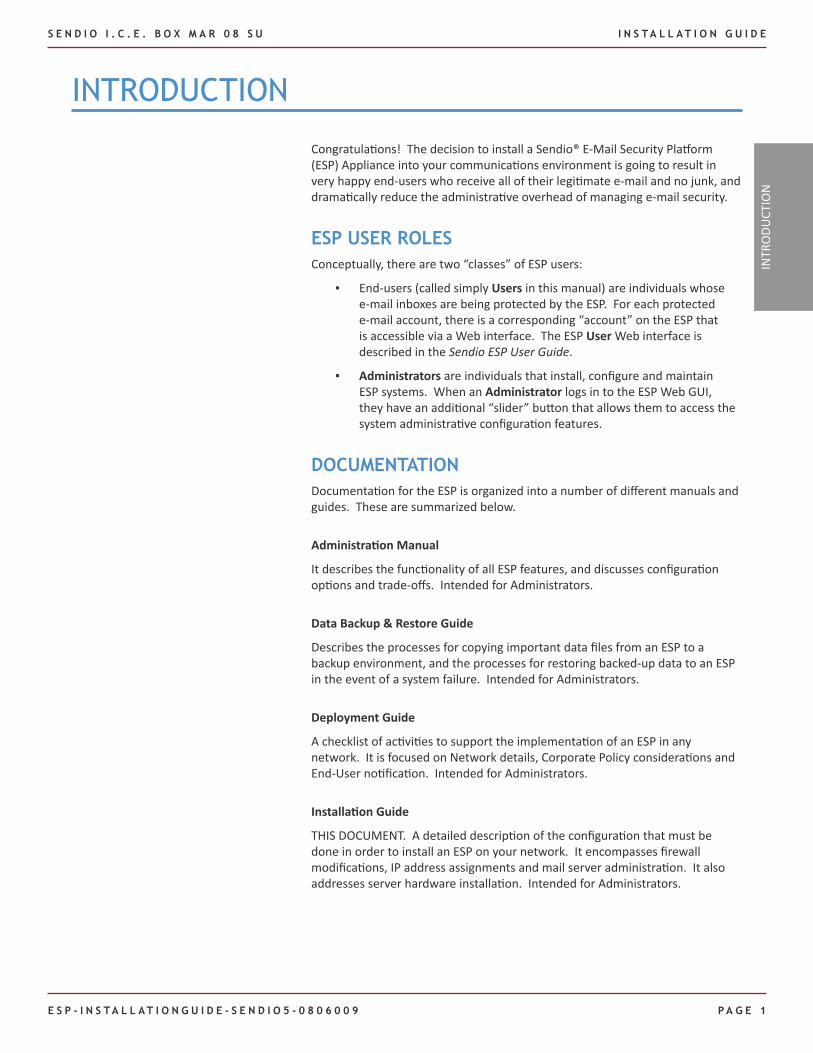
InTRoduCTIon
Congratulations! The decision to install a Sendio® E-Mail Security Platform (ESP) Appliance into your communications environment is going to result in very happy end-users who receive all of their legitimate e-mail and no junk, and dramatically reduce the administrative overhead of managing e-mail security.
ESP USER ROLESConceptually, there are two “classes” of ESP users:
End-users (called simply ▪ Users in this manual) are individuals whose e-mail inboxes are being protected by the ESP. For each protected e-mail account, there is a corresponding “account” on the ESP that is accessible via a Web interface. The ESP User Web interface is described in the Sendio ESP User Guide.
Administrators ▪ are individuals that install, configure and maintain ESP systems. When an Administrator logs in to the ESP Web GUI, they have an additional “slider” button that allows them to access the system administrative configuration features.
DOCUMENTATIONDocumentation for the ESP is organized into a number of different manuals and guides. These are summarized below.
Administration Manual
It describes the functionality of all ESP features, and discusses configuration options and trade-offs. Intended for Administrators.
Data Backup & Restore Guide
Describes the processes for copying important data files from an ESP to a backup environment, and the processes for restoring backed-up data to an ESP in the event of a system failure. Intended for Administrators.
Deployment Guide
A checklist of activities to support the implementation of an ESP in any network. It is focused on Network details, Corporate Policy considerations and End-User notification. Intended for Administrators.
Installation Guide
THIS DOCUMENT. A detailed description of the configuration that must be done in order to install an ESP on your network. It encompasses firewall modifications, IP address assignments and mail server administration. It also addresses server hardware installation. Intended for Administrators.
INTR
ODU
CTIO
N
I N S T A L L A T I O N G U I D E S E N D I O E S P 5 . 0
PA G E 2 E s P I n s T A l l A T I o n G u I d E
Quick Start Guide
An abbreviated 13-step process for complete ESP installation and mail routing. Comprehensive installation details are found in the Installation Guide. Intended for Administrators.
User Guide
Describes in vivid detail the User experience in an ESP GUI. It is appropriate to post this tutorial (in .PDF format) on a company intranet for User reference. Intended for Users.
User Quick Reference
Designed to be an easy reference for the most commonly used functions of the User interface on an ESP. Intended for Users.
CONVENTIONS IN THIS MANUAL
NOTE: A Note is information that deserves special consideration.
TROUBLESHOOTING TIP: A Troubleshooting Tip provides information that has been known to help solve various problems.
WARNING: A Warning identifies information that could lead to unintended consequences if not properly considered.
Data that is typed into a field in the GUI is identified using this Courier font.
Menu Commands
The ESP Web interface has menu commands that you follow to change display pages, open dialog boxes and initiate certain actions. Primary menu commands (or paths through the interface) are shown in bold type in the format Admin > System > Outbound Control. This example would mean:
the Admin menu ▪
the System button ▪
the Outbound Control tabbed page ▪
The options on drop-down menus, such as Accept Contacts only, are shown in italics.
ESP Terminology
Words that have special meaning within the context of ESP operations are shown in italics, such as Accept Contact, Established or Waiting.
S E N D I O E S P 5 . 0 I N S T A L L A T I O N G U I D E
E S P I N S T A L L A T I O N G U I D E P A G E 3
Before diving in to all of the details involved in installing a Sendio ESP e-mail Integrity Services Appliance, it will be useful to first describe a number of concepts and definitions that will help the reader of this manual as they go through the deployment process.
Platform
The ESP is a custom-built server appliance running a high-security implementation of the Linux operating system. Sendio has developed a large number of e-mail message processing “services” that run on the system. Many of these services are administratively configurable.
Message Flow
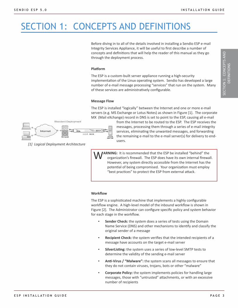
The ESP is installed “logically” between the Internet and one or more e-mail servers (e.g. MS Exchange or Lotus Notes) as shown in Figure [1]. The corporate MX (Mail eXchange) record in DNS is set to point to the ESP, causing all e-mail
from the Internet to be routed to the ESP. The ESP receives the messages, processing them through a series of e-mail integrity services, eliminating the unwanted messages, and forwarding the remaining e-mail to the e-mail server(s) for delivery to end-users.
WARNING: It is recommended that the ESP be installed “behind” the organization’s firewall. The ESP does have its own internal firewall. However, any system directly accessible from the Internet has the potential of being compromised. Your organization must employ “best practices” to protect the ESP from external attack.
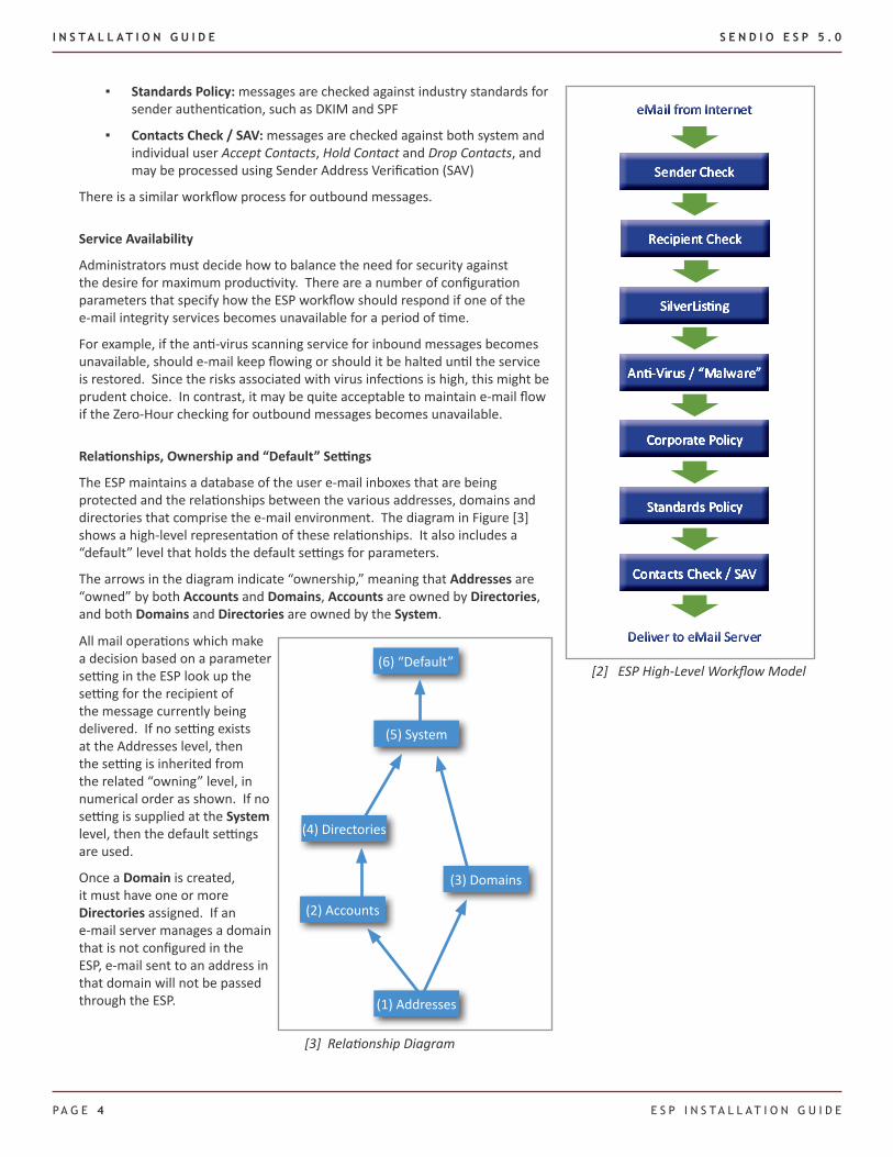
Workflow
The ESP is a sophisticated machine that implements a highly configurable workflow engine. A high-level model of the inbound workflow is shown in Figure [2]. The Administrator can configure specific policy and system behavior for each stage in the workflow.
Sender Check: ▪ the system does a series of tests using the Domain Name Service (DNS) and other mechanisms to identify and classify the original sender of a message
Recipient Check: ▪ the system verifies that the intended recipients of a message have accounts on the target e-mail server
SilverListing: ▪ the system uses a series of low-level SMTP tests to determine the validity of the sending e-mail server
Anti-Virus / “Malware”: ▪ the system scans all messages to ensure that they do not contain viruses, trojans, bots or other “malware”
Corporate Policy: ▪ the system implements policies for handling large messages, those with “untrusted” attachments, or with an excessive number of recipients
sECTIon 1: ConCEPTs And dEFInITIons
SECT
ION
1:
CON
CEPT
S AN
D DE
FIN
ITIO
NS
[1] Logical Deployment Architecture
I N S T A L L A T I O N G U I D E S E N D I O E S P 5 . 0
PA G E 4 E s P I n s T A l l A T I o n G u I d E
Standards Policy: ▪ messages are checked against industry standards for sender authentication, such as DKIM and SPF
Contacts Check / SAV: ▪ messages are checked against both system and individual user Accept Contacts, Hold Contact and Drop Contacts, and may be processed using Sender Address Verification (SAV)
There is a similar workflow process for outbound messages.
Service Availability
Administrators must decide how to balance the need for security against the desire for maximum productivity. There are a number of configuration parameters that specify how the ESP workflow should respond if one of the e-mail integrity services becomes unavailable for a period of time.
For example, if the anti-virus scanning service for inbound messages becomes unavailable, should e-mail keep flowing or should it be halted until the service is restored. Since the risks associated with virus infections is high, this might be prudent choice. In contrast, it may be quite acceptable to maintain e-mail flow if the Zero-Hour checking for outbound messages becomes unavailable.
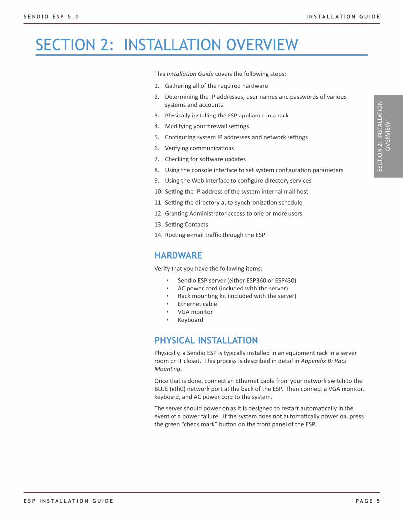
Relationships, Ownership and “Default” Settings
The ESP maintains a database of the user e-mail inboxes that are being protected and the relationships between the various addresses, domains and directories that comprise the e-mail environment. The diagram in Figure [3] shows a high-level representation of these relationships. It also includes a “default” level that holds the default settings for parameters.
The arrows in the diagram indicate “ownership,” meaning that Addresses are “owned” by both Accounts and Domains, Accounts are owned by Directories, and both Domains and Directories are owned by the System.
(1) Addresses
(2) Accounts
(3) Domains
(4) Directories
(5) System
(6) “Default”
[3] Relationship Diagram
All mail operations which make a decision based on a parameter setting in the ESP look up the setting for the recipient of the message currently being delivered. If no setting exists at the Addresses level, then the setting is inherited from the related “owning” level, in numerical order as shown. If no setting is supplied at the System level, then the default settings are used.
Once a Domain is created, it must have one or more Directories assigned. If an e-mail server manages a domain that is not configured in the ESP, e-mail sent to an address in that domain will not be passed through the ESP.
[2] ESP High-Level Workflow Model
S E N D I O E S P 5 . 0 I N S T A L L A T I O N G U I D E
E S P I N S T A L L A T I O N G U I D E P A G E 5
This Installation Guide covers the following steps:
Gathering all of the required hardware1.
Determining the IP addresses, user names and passwords of various 2. systems and accounts
Physically installing the ESP appliance in a rack3.
Modifying your firewall settings4.
Configuring system IP addresses and network settings5.
Verifying communications6.
Checking for software updates7.
Using the console interface to set system configuration parameters8.
Using the Web interface to configure directory services9.
Setting the IP address of the system internal mail host10.
Setting the directory auto-synchronization schedule11.
Granting Administrator access to one or more users12.
Setting Contacts13.
Routing e-mail traffic through the ESP 14.
HARDWAREVerify that you have the following items:
Sendio ESP server (either ESP360 or ESP430) ▪AC power cord (included with the server) ▪Rack mounting kit (included with the server) ▪Ethernet cable ▪VGA monitor ▪Keyboard ▪
PHYSICAL INSTALLATIONPhysically, a Sendio ESP is typically installed in an equipment rack in a server room or IT closet. This process is described in detail in Appendix B: Rack Mounting.
Once that is done, connect an Ethernet cable from your network switch to the BLUE (eth0) network port at the back of the ESP. Then connect a VGA monitor, keyboard, and AC power cord to the system.
The server should power on as it is designed to restart automatically in the event of a power failure. If the system does not automatically power on, press the green “check mark” button on the front panel of the ESP.
sECTIon 2: InsTAllATIon oVERVIEW
SECT
ION
2:
INST
ALLA
TIO
N
OVE
RVIE
W
I N S T A L L A T I O N G U I D E S E N D I O E S P 5 . 0
PA G E 6 E s P I n s T A l l A T I o n G u I d E
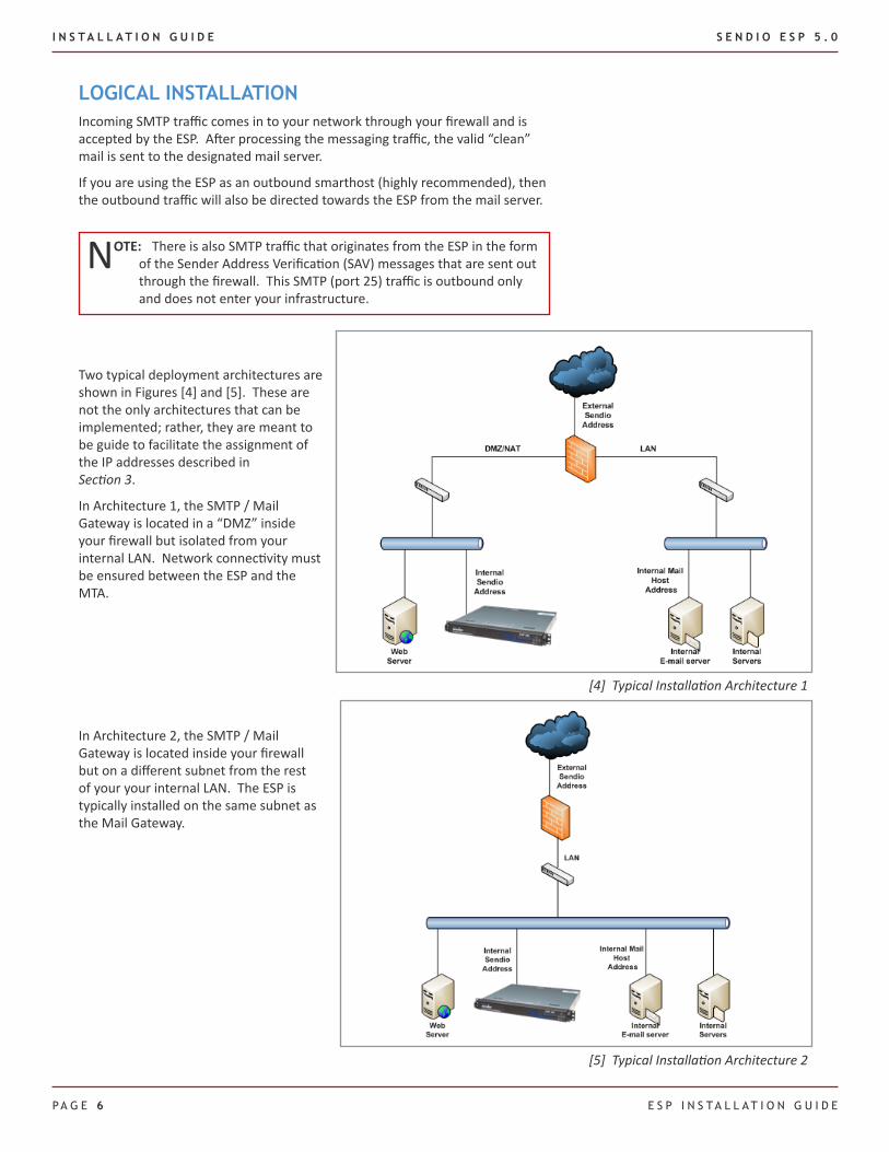
[5] Typical Installation Architecture 2
LOGICAL INSTALLATIONIncoming SMTP traffic comes in to your network through your firewall and is accepted by the ESP. After processing the messaging traffic, the valid “clean” mail is sent to the designated mail server.
If you are using the ESP as an outbound smarthost (highly recommended), then the outbound traffic will also be directed towards the ESP from the mail server.
NOTE: There is also SMTP traffic that originates from the ESP in the form of the Sender Address Verification (SAV) messages that are sent out through the firewall. This SMTP (port 25) traffic is outbound only and does not enter your infrastructure.
[4] Typical Installation Architecture 1
Two typical deployment architectures are shown in Figures [4] and [5]. These are not the only architectures that can be implemented; rather, they are meant to be guide to facilitate the assignment of the IP addresses described in Section 3.
In Architecture 1, the SMTP / Mail Gateway is located in a “DMZ” inside your firewall but isolated from your internal LAN. Network connectivity must be ensured between the ESP and the MTA.
In Architecture 2, the SMTP / Mail Gateway is located inside your firewall but on a different subnet from the rest of your your internal LAN. The ESP is typically installed on the same subnet as the Mail Gateway.
S E N D I O E S P 5 . 0 I N S T A L L A T I O N G U I D E
E S P I N S T A L L A T I O N G U I D E P A G E 7
DEVICE IP ADDRESS SUBNET MASK
External Cluster Address
Internal Cluster Address
ESP External Address (Secondary)
ESP Internal Address (Secondary)
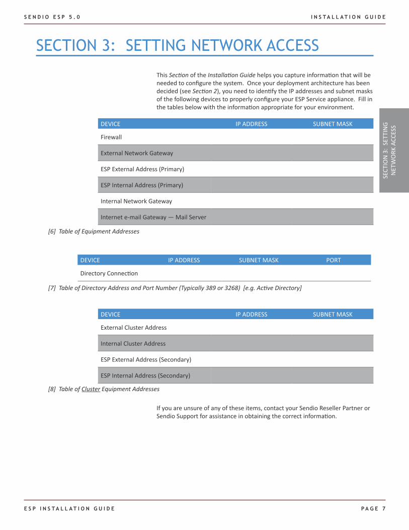
This Section of the Installation Guide helps you capture information that will be needed to configure the system. Once your deployment architecture has been decided (see Section 2), you need to identify the IP addresses and subnet masks of the following devices to properly configure your ESP Service appliance. Fill in the tables below with the information appropriate for your environment.
sECTIon 3: sETTInG nETWoRK ACCEss
DEVICE IP ADDRESS SUBNET MASK
Firewall
External Network Gateway
ESP External Address (Primary)
ESP Internal Address (Primary)
Internal Network Gateway
Internet e-mail Gateway — Mail Server
If you are unsure of any of these items, contact your Sendio Reseller Partner or Sendio Support for assistance in obtaining the correct information.
DEVICE IP ADDRESS SUBNET MASK PORT
Directory Connection
[6] Table of Equipment Addresses
[7] Table of Directory Address and Port Number (Typically 389 or 3268) [e.g. Active Directory]
[8] Table of Cluster Equipment AddressesSE
CTIO
N 3
: SE
TTIN
G N
ETW
ORK
ACC
ESS
I N S T A L L A T I O N G U I D E S E N D I O E S P 5 . 0
PA G E 8 E s P I n s T A l l A T I o n G u I d E
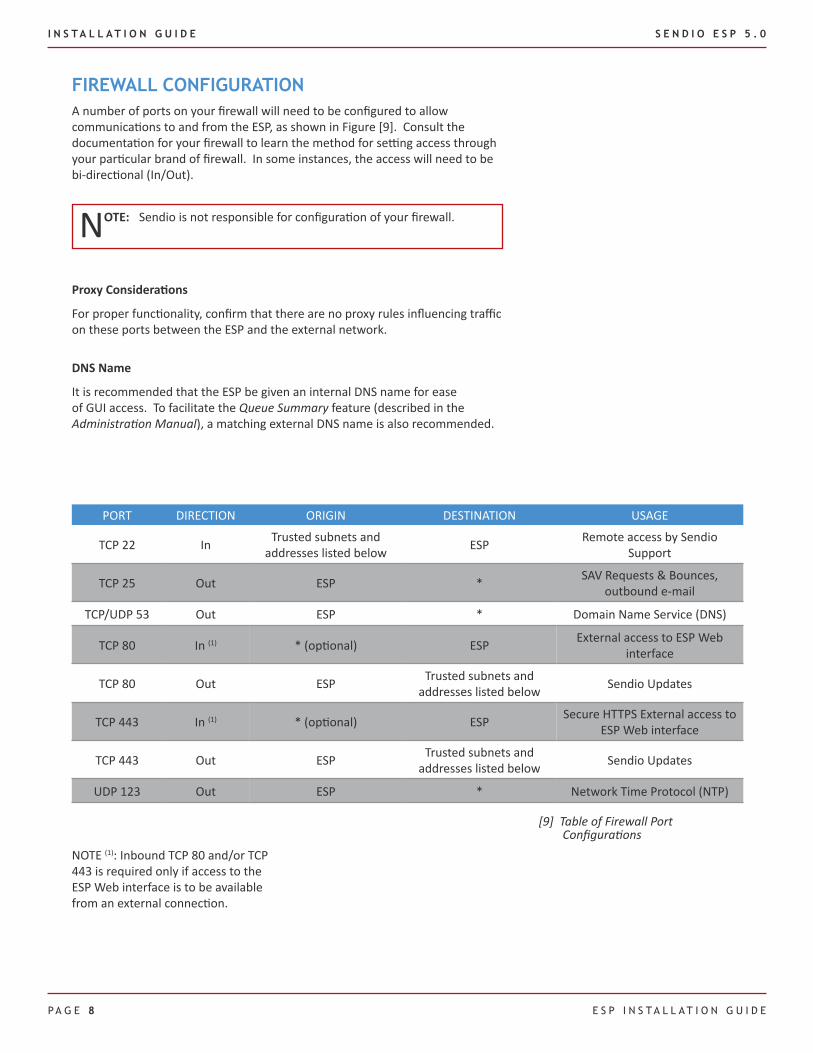
FIREWALL CONFIGURATIONA number of ports on your firewall will need to be configured to allow communications to and from the ESP, as shown in Figure [9]. Consult the documentation for your firewall to learn the method for setting access through your particular brand of firewall. In some instances, the access will need to be bi-directional (In/Out).
NOTE: Sendio is not responsible for configuration of your firewall.
Proxy Considerations
For proper functionality, confirm that there are no proxy rules influencing traffic on these ports between the ESP and the external network.
DNS Name
It is recommended that the ESP be given an internal DNS name for ease of GUI access. To facilitate the Queue Summary feature (described in the Administration Manual), a matching external DNS name is also recommended.
PORT DIRECTION ORIGIN DESTINATION USAGE
TCP 22 In Trusted subnets and addresses listed below ESP Remote access by Sendio
Support
TCP 25 Out ESP * SAV Requests & Bounces, outbound e-mail
TCP/UDP 53 Out ESP * Domain Name Service (DNS)
TCP 80 In (1) * (optional) ESP External access to ESP Web interface
TCP 80 Out ESP Trusted subnets and addresses listed below Sendio Updates
TCP 443 In (1) * (optional) ESP Secure HTTPS External access to ESP Web interface
TCP 443 Out ESP Trusted subnets and addresses listed below Sendio Updates
UDP 123 Out ESP * Network Time Protocol (NTP)
[9] Table of Firewall Port Configurations
NOTE (1): Inbound TCP 80 and/or TCP 443 is required only if access to the ESP Web interface is to be available from an external connection.
S E N D I O E S P 5 . 0 I N S T A L L A T I O N G U I D E
E S P I N S T A L L A T I O N G U I D E P A G E 9
Trusted Sendio Subnets and Addresses
The following is Sendio’s trusted subnet and addresses:
Starting IP address: 64.58.146.32Subnet Mask: 255.255.255.224 [27 bits]Range Notation: 64.58.146.32/27 (255.255.255.224)Address range: 64.58.146.32 - 64.58.146.63
The following addresses are Commtouch services that require TCP 80 Outbound access:
216.163.188.451. 213.52.240.240 OR2. 65.74.168.2103. 216.163.188.434.
The firewall and any other security devices must permit the following file types over port 80/443 for update purposes: .rpm, .xml, .xml.gz, .xml.md5, .tar.gz, .avc, .ini, .dt, .cfg, .mhk, .lst, .set, .vnd, .klb, and .ver.
resolver1.t.ctmail.com1. resolver2.t.ctmail.com2. resolver3.t.ctmail.com3. resolver4.t.ctmail.com4. resolver5.t.ctmail.com5.
SECT
ION
3:
SETT
ING
NET
WO
RK A
CCES
S

I N S T A L L A T I O N G U I D E S E N D I O E S P 5 . 0
PA G E 1 0 E s P I n s T A l l A T I o n G u I d E
This page intentionally left blank
S E N D I O E S P 5 . 0 I N S T A L L A T I O N G U I D E
E S P I N S T A L L A T I O N G U I D E P A G E 1 1
sECTIon 4: usInG THE ConsolE InTERFACE
CONNECTING THE HARDWAREWith the ESP server installed in a rack (per Appendix B), attach a monitor and a keyboard (either PS/2 or USB) to the system. When the power cord is plugged in, the system should automatically start up.
NOTE: Do not attach the system to the network before you have set the network connection parameters described below.
If the system has come preconfigured from your reseller, you may connect the device to your network using the blue network port.
WARNING: If you are replacing an existing network appliance and re-using the same IP address, you might cause an IP conflict. If this is the case, please modify the IP address on your ESP to allow for initial installation access and updates prior to connecting it to your network.
ADMINISTRATIVE INTERFACESThere are two distinct interfaces for configuring and managing an ESP:
A console interface that provides access to “low level” connectivity and ▪security functions (sometimes referred to as the sysconfig “shell”)
A Web interface for access to “application level” parameters that set ▪policy and describe workflow
This Sendio ESP Installation Guide describes the features and functions of the console interface. The Sendio ESP Administration Manual documents the Web interface.
CONSOLE INTERFACE OVERVIEWBoth the console interface and the Web interface for an ESP share a common basic layout and usage model. On a screen, there is a navigation menu on the left side and an information display area on the right.
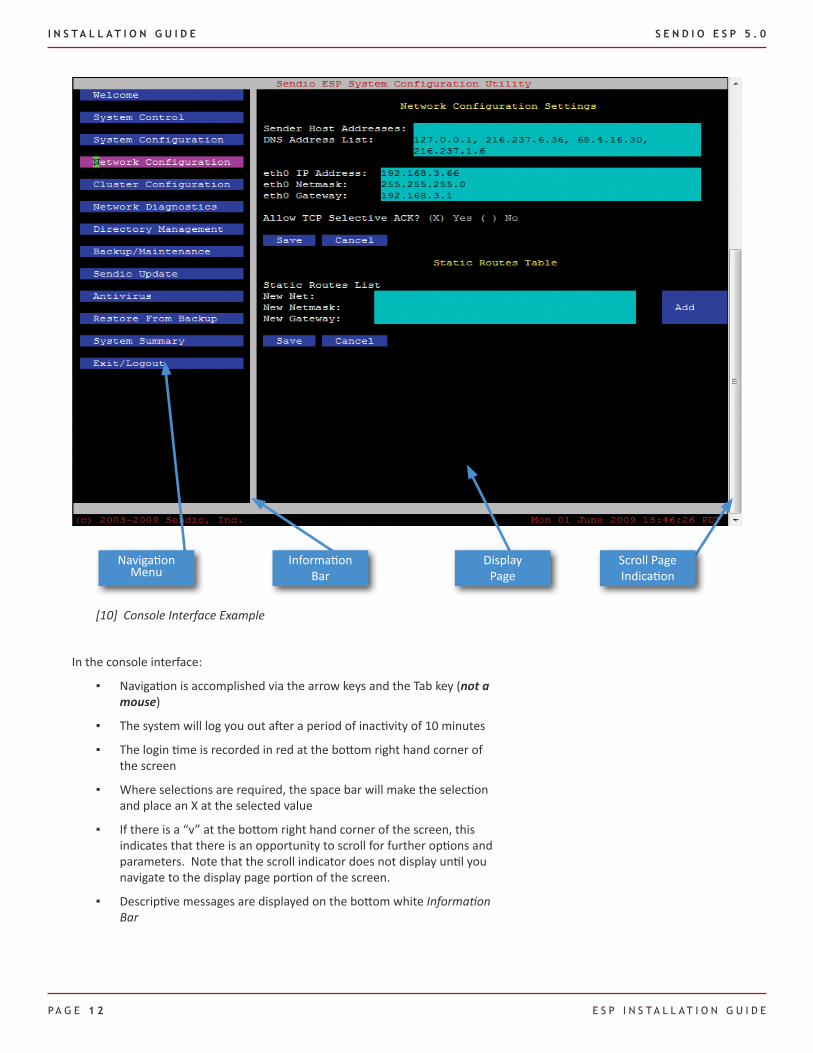
Selecting different menu options causes the display portion of the page to change. The console interface is character-based, and is controlled via the keyboard arrow keys. An example of the console interface is shown in Figure [10].
SECT
ION
4:
USI
NG
THE
CON
SOLE
INTE
RFAC
E
I N S T A L L A T I O N G U I D E S E N D I O E S P 5 . 0
PA G E 1 2 E s P I n s T A l l A T I o n G u I d E
In the console interface:
Navigation is accomplished via the arrow keys and the Tab key ( ▪ not a mouse)
The system will log you out after a period of inactivity of 10 minutes ▪
The login time is recorded in red at the bottom right hand corner of ▪the screen
Where selections are required, the space bar will make the selection ▪and place an X at the selected value
If there is a “v” at the bottom right hand corner of the screen, this ▪indicates that there is an opportunity to scroll for further options and parameters. Note that the scroll indicator does not display until you navigate to the display page portion of the screen.
Descriptive messages are displayed on the bottom white ▪ Information Bar
[10] Console Interface Example
NavigationMenu
Scroll Page Indication
Information Bar
Display Page

S E N D I O E S P 5 . 0 I N S T A L L A T I O N G U I D E
E S P I N S T A L L A T I O N G U I D E P A G E 1 3
CONFIGURING AN ESP
Step 1: Logging InWhen an ESP is powered on, it loads a version of the Linux operating system. This boot process takes approximately one minute.
When the boot process is finished, a prompt will appear as shown in Figure [11].
The default console login is:
Login: sysconfig Password: admin
The first time you log in to the ESP, the Welcome page, shown in Figure [12], will be displayed.
[11] Console Interface Login
[12] Initial Console Interface Welcome Page
You will be prompted to immediately change the sysconfig password. This password change is required before you can log in as an Administrator to the ESP Web interface with the sysconfig user name.
The new password must contain between 5 and 8 alphanumeric characters. No special characters may be used. Once the password has been changed, the system will require that you log back in, where you will see the standard Welcome page [13].
SECT
ION
4:
LOGG
ING
IN
I N S T A L L A T I O N G U I D E S E N D I O E S P 5 . 0
PA G E 1 4 E s P I n s T A l l A T I o n G u I d E
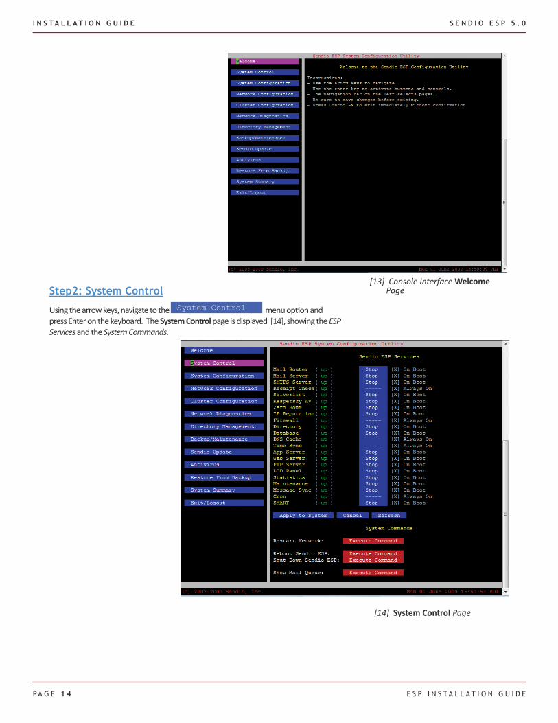
Step2: System Control
Using the arrow keys, navigate to the System Control menu option and press Enter on the keyboard. The System Control page is displayed [14], showing the ESP Services and the System Commands.
[13] Console Interface Welcome Page
[14] System Control Page
S E N D I O E S P 5 . 0 I N S T A L L A T I O N G U I D E
E S P I N S T A L L A T I O N G U I D E P A G E 1 5
System Control > ESP Services
All of the services supported by the ESP are listed in a table. For each service, the table shows the Service Name, the status of the service (up or down), a status control (Stop or Start), and a flag [X] for whether the service should start automatically when the system boots up.
In most cases, all of the services except the Directory service should be set to up. The Directory service should be up only if you are running the Sendio Onboard Directory instead of an external directory such as Active Directory.
NOTE: When a new ESP is shipped from the factory and first installed, the Zero Hour and Mail Server services may be down. When the Zero Hour service is up, it tries to connect over the Internet to a remote monitoring service. If an ESP does not yet have network configuration settings, it can take several minutes for the Zero Hour service to “time out” so this service is typically shipped down as a convenience for the system installer. As soon as the ESP is configured, turn the Zero Hour service up.
In order to stop and start services, move the cursor to the status control start/stop column and press either the space bar or the Enter key to toggle the service value.
All of the services — except possibly the Directory service — should have an X in front of the On Boot label. This is an indication that if the ESP reboots, or is powered off and then powered back on, these services will automatically restart.
If any changes are made to the parameters, move the cursor to the Apply to System button and press Enter. The system will modify the services as
requested and display a dialog box that indicates a successful result.
In the case that there is an error code returned or the service status contains a series of three question marks (???), please contact Sendio Support for assistance.
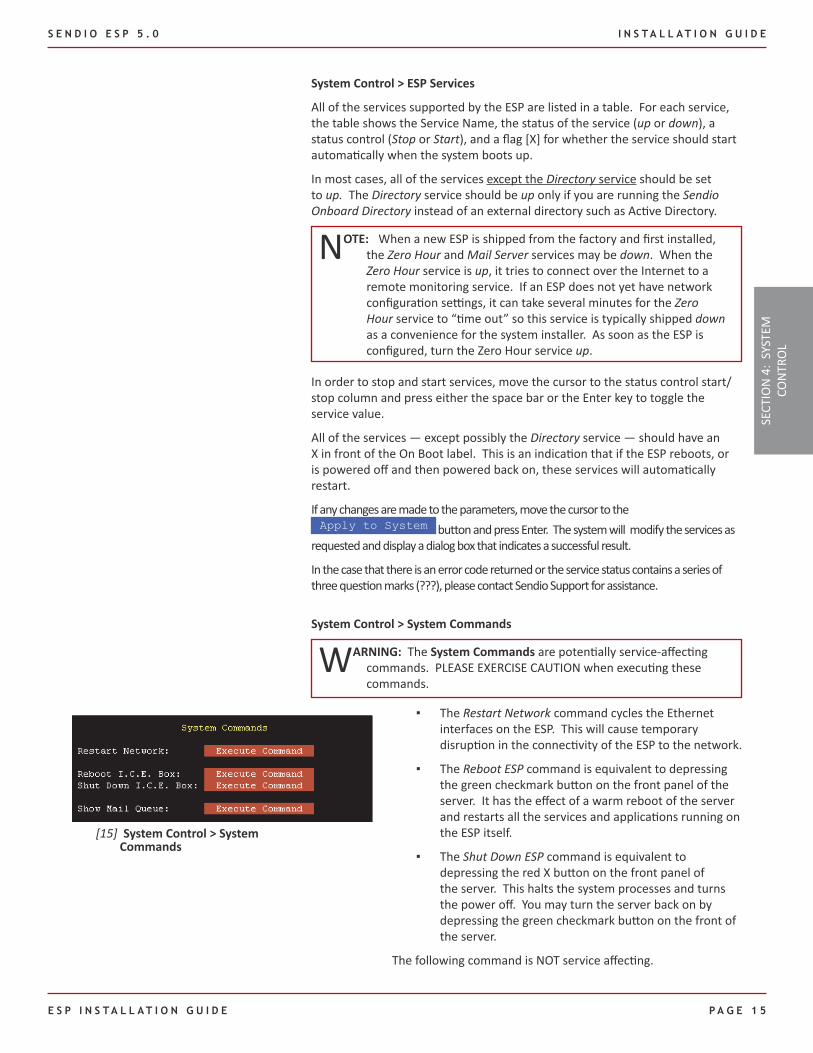
System Control > System Commands
WARNING: The System Commands are potentially service-affecting commands. PLEASE EXERCISE CAUTION when executing these commands.
The ▪ Restart Network command cycles the Ethernet interfaces on the ESP. This will cause temporary disruption in the connectivity of the ESP to the network.
The ▪ Reboot ESP command is equivalent to depressing the green checkmark button on the front panel of the server. It has the effect of a warm reboot of the server and restarts all the services and applications running on the ESP itself.
The ▪ Shut Down ESP command is equivalent to depressing the red X button on the front panel of the server. This halts the system processes and turns the power off. You may turn the server back on by depressing the green checkmark button on the front of the server.
The following command is NOT service affecting.
[15] System Control > System Commands
SECT
ION
4:
SYST
EM
CON
TRO
L
I N S T A L L A T I O N G U I D E S E N D I O E S P 5 . 0
PA G E 1 6 E s P I n s T A l l A T I o n G u I d E
Show Mail Queue ▪ will display the messages in the mail queues in the server. Any significant backup in the Local Queue is indicative of an issue on the SMTP server at the next point in the messaging stream. If the internal MTA is not accepting mail, the Local Queue will build up. The Todo queue in the ESP shows the number of messages that the ESP needs to process. If there is a significant buildup of this queue for any period of time, please contact your reseller. Sendio Support is notified automatically through our monitoring system if any of the queues become excessively large.
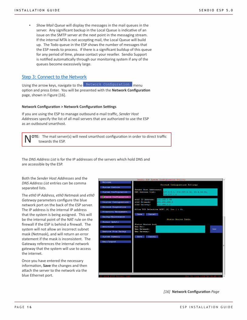
Step 3: Connect to the Network
Using the arrow keys, navigate to the Network Configuration menu option and press Enter. You will be presented with the Network Configuration page, shown in Figure [16].
Network Configuration > Network Configuration Settings
If you are using the ESP to manage outbound e-mail traffic, Sender Host Addresses specify the list of all mail servers that are authorized to use the ESP as an outbound smarthost.
NOTE: The mail server(s) will need smarthost configuration in order to direct traffic towards the ESP.
The DNS Address List is for the IP addresses of the servers which hold DNS and are accessible by the ESP.
[16] Network Configuration Page
Both the Sender Host Addresses and the DNS Address List entries can be comma separated lists.
The eth0 IP Address, eth0 Netmask and eth0 Gateway parameters configure the blue network port on the back of the ESP server. The IP address is the internal IP address that the system is being assigned. This will be the internal point of the NAT rule on the firewall if the ESP is behind a firewall. The system will not allow an incorrect subnet mask (Netmask), and will return an error statement if the mask is inconsistent. The Gateway references the internal network gateway that the system will use to access the internet.
Once you have entered the necessary information, Save the changes and then attach the server to the network via the blue Ethernet port.
S E N D I O E S P 5 . 0 I N S T A L L A T I O N G U I D E
E S P I N S T A L L A T I O N G U I D E P A G E 1 7
NOTE: If a failure is suspected on the eth0 of the ESP, the eth1 can be used for traffic. This redirection is specified via the Override parameter. The Override feature cannot be used when a cluster is in place.
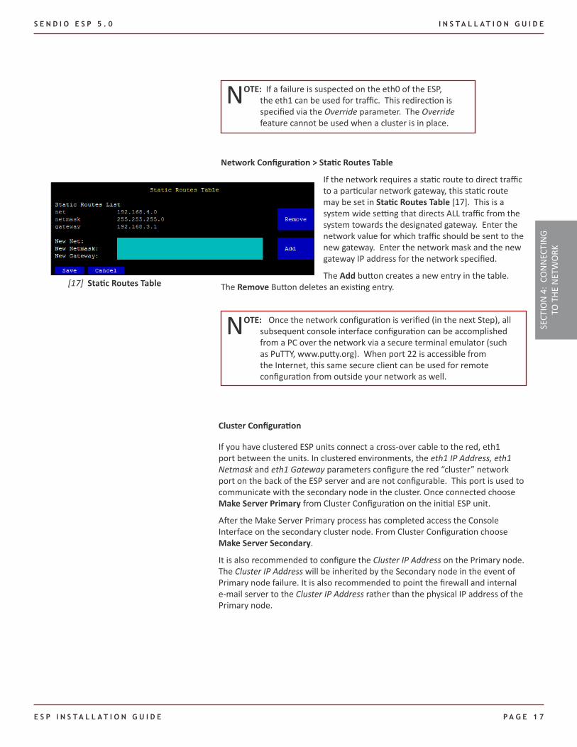
Network Configuration > Static Routes Table
If the network requires a static route to direct traffic to a particular network gateway, this static route may be set in Static Routes Table [17]. This is a system wide setting that directs ALL traffic from the system towards the designated gateway. Enter the network value for which traffic should be sent to the new gateway. Enter the network mask and the new gateway IP address for the network specified.
The Add button creates a new entry in the table. The Remove Button deletes an existing entry.[17] Static Routes Table
NOTE: Once the network configuration is verified (in the next Step), all subsequent console interface configuration can be accomplished from a PC over the network via a secure terminal emulator (such as PuTTY, www.putty.org). When port 22 is accessible from the Internet, this same secure client can be used for remote configuration from outside your network as well.
Cluster Configuration
If you have clustered ESP units connect a cross-over cable to the red, eth1 port between the units. In clustered environments, the eth1 IP Address, eth1 Netmask and eth1 Gateway parameters configure the red “cluster” network port on the back of the ESP server and are not configurable. This port is used to communicate with the secondary node in the cluster. Once connected choose Make Server Primary from Cluster Configuration on the initial ESP unit.
After the Make Server Primary process has completed access the Console Interface on the secondary cluster node. From Cluster Configuration choose Make Server Secondary.
It is also recommended to configure the Cluster IP Address on the Primary node. The Cluster IP Address will be inherited by the Secondary node in the event of Primary node failure. It is also recommended to point the firewall and internal e-mail server to the Cluster IP Address rather than the physical IP address of the Primary node.
SECT
ION
4:
CON
NEC
TIN
G TO
THE
NET
WO
RK
I N S T A L L A T I O N G U I D E S E N D I O E S P 5 . 0
PA G E 1 8 E s P I n s T A l l A T I o n G u I d E
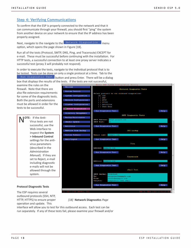
Step 4: Verifying CommunicationsTo confirm that the ESP is properly connected to the network and that it can communicate through your firewall, you should first “ping” the system from another device on your network to ensure that the IP address has been properly assigned.
Next, navigate to the navigate to the Network Diagnostics menu option, which opens the page shown in Figure [18].
Run all of the tests (Protocol, SMTP, DNS, Ping, and Traceroute) EXCEPT for e-mail. These must be successful before continuing with the installation. For HTTP tests, a successful connection to at least one proxy server indicates a successful test (proxy 3 will probably not respond).
In order to execute the tests, navigate to the individual protocol that is to be tested. Tests can be done on only a single protocol at a time. Tab to the Run Diagnostic Test button and press Enter. There will be a dialog
box that displays the results of the tests. If the tests are not successful, examine the rules on the firewall. Note that there are also file extension requirements for some of the diagnostic tests. Both the ports and extensions must be allowed in order for the tests to be successful.
NOTE: If the Anti-Virus tests are not successful, use the Web interface to inspect the System > Inbound Control settings for the anti-virus parameters (described in the Administration Manual). If they are set to Reject, e-mail including diagnostic e-mails will not be allowed through the system.
Protocol Diagnostic Tests
The ESP requires several outbound protocols (SSH, NTP, HTTP, HTTPS) to ensure proper operation and update. This interface will allow you to test for this outbound access. Each test can be run separately. If any of these tests fail, please examine your firewall and/or
[18] Network Diagnostics Page
S E N D I O E S P 5 . 0 I N S T A L L A T I O N G U I D E
E S P I N S T A L L A T I O N G U I D E P A G E 1 9
network configuration for any blockage of this traffic type. These tests not only verify port level access, but also the file extensions that are required to have passage through your firewall.
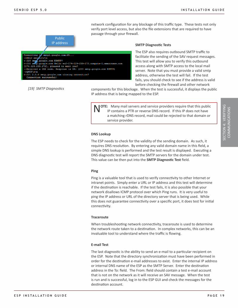
SMTP Diagnostic Tests
The ESP also requires outbound SMTP traffic to facilitate the sending of the SAV request messages. This test will allow you to verify this outbound access along with SMTP access to the local mail server. Note that you must provide a valid smtp address, otherwise the test will fail. If the test fails, you should check to see if the address is valid before checking the firewall and other network
components for this blockage. When the test is successful, it displays the public IP address that is being mapped to the ESP.
NOTE: Many mail servers and service providers require that this public IP contains a PTR or reverse DNS record. If this IP does not have a matching rDNS record, mail could be rejected to that domain or service provider.
DNS Lookup
The ESP needs to check for the validity of the sending domain. As such, it requires DNS resolution. By entering any valid domain name in this field, a simple DNS lookup is performed and the test result is displayed. Executing a DNS diagnostic test will report the SMTP servers for the domain under test. This value can be then put into the SMTP Diagnostic Test field.
Ping
Ping is a valuable tool that is used to verify connectivity to other Internet or intranet points. Simply enter a URL or IP address and this test will determine if the destination is reachable. If the test fails, it is also possible that your network disallows ICMP protocol over which Ping runs. It is very useful to ping the IP address or URL of the directory server that is being used. While this does not guarantee connectivity over a specific port, it does test for initial connectivity.
Traceroute
When troubleshooting network connectivity, traceroute is used to determine the network route taken to a destination. In complex networks, this can be an invaluable tool to understand where the traffic is flowing.
E-mail Test
The last diagnostic is the ability to send an e-mail to a particular recipient on the ESP. Note that the directory synchronization must have been performed in order for the destination e-mail addresses to exist. Enter the internal IP address or internal DNS name of the ESP as the SMTP Server. Enter the destination address in the To: field. The From: field should contain a test e-mail account that is not on the network as it will receive an SAV message. When the test is run and is successful, log in to the ESP GUI and check the messages for the destination account.
[19] SMTP Diagnostics
SECT
ION
4:
VERI
FYIN
G CO
MM
UN
ICAT
ION
S
Public IP address
I N S T A L L A T I O N G U I D E S E N D I O E S P 5 . 0
PA G E 2 0 E s P I n s T A l l A T I o n G u I d E
If SAV is turned on then the message will be in the pending queue until the From: sender replies or until you manually accept the message. If you accept the message or the SAV value is turned off, then the mail will be accepted through the to the destination mailbox on the mail server. To view this, please click on the View button and select delivered messages on the drop down list. If the Recipient received the message, and it is not displaying in the ESP, then the message did not travel the intended path through the ESP. Note that if the ESP is not yet configured to receive traffic, then the external mail box that has received the SAV message will not be able to properly respond as the mail for that domain will not be received at the ESP. In order to test that outbound mail can be sent through the ESP, enter the external recipient address as the recipient and enter a local address in the From field. Once the test has been successful, please reference the outbound queue for the address that was designated in the From field. The diagnostic message should be shown there.
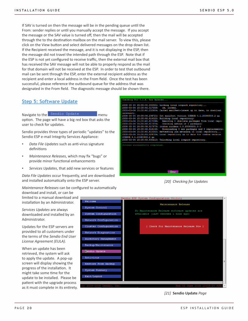
Step 5: Software Update
Navigate to the Sendio Update menu option. The page will have a big red box that asks the user to check for updates.
Sendio provides three types of periodic “updates” to the Sendio ESP e-mail Integrity Services Appliance:
Data File Updates ▪ such as anti-virus signature definitions
Maintenance Releases ▪ , which may fix “bugs” or provide minor functional enhancements
Services Updates ▪ , that add new services or features
Data File Updates occur frequently, and are downloaded and installed automatically onto the ESP server.
Maintenance Releases can be configured to automatically download and install, or can be limited to a manual download and installation by an Administrator.
Services Updates are always downloaded and installed by an Administrator.
Updates for the ESP servers are provided to all customers under the terms of the Sendio End User License Agreement (EULA).
When an update has been retrieved, the system will ask to apply the update. A pop-up screen will display showing the progress of the installation. It might take some time for the update to be installed. Please be patient with the upgrade process as it must complete in its entirety.
[21] Sendio Update Page
[20] Checking for Updates
S E N D I O E S P 5 . 0 I N S T A L L A T I O N G U I D E
E S P I N S T A L L A T I O N G U I D E P A G E 2 1
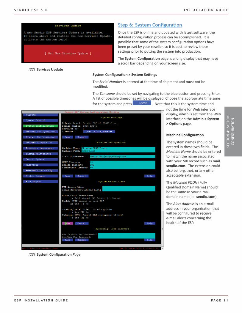
Step 6: System ConfigurationOnce the ESP is online and updated with latest software, the detailed configuration process can be accomplished. It is possible that some of the system configuration options have been preset by your reseller, so it is best to review these settings prior to putting the system into production.
The System Configuration page is a long display that may have a scroll bar depending on your screen size.
System Configuration > System Settings
The Serial Number is entered at the time of shipment and must not be modified.
The Timezone should be set by navigating to the blue button and pressing Enter. A list of possible timezones will be displayed. Choose the appropriate time zone for the system and press Save . Note that this is the system time and
[22] Services Update
[23] System Configuration Page
not the time for Web interface display, which is set from the Web interface on the Admin > System > Options page.
Machine Configuration
The system names should be entered in these two fields. The Machine Name should be entered to match the name associated with your MX record such as mail.sendio.com. The extension could also be .org, .net, or any other acceptable extension.
The Machine FQDN (Fully Qualified Domain Name) should be the same as your e-mail domain name (i.e. sendio.com).
The Alert Address is an e-mail address in your organization that will be configured to receive e-mail alerts concerning the health of the ESP. SE
CTIO
N 4
: SY
STEM
CO
NFI
GURA
TIO
N
I N S T A L L A T I O N G U I D E S E N D I O E S P 5 . 0
PA G E 2 2 E s P I n s T A l l A T I o n G u I d E
The next three values are typically left at the default settings. These are the SMTP transaction timeout values. These values are in seconds and are defined as follows:
SMTP Timeout: This is the maximum amount of time for finishing an operation with the remote SMTP server.
Remote Timeout: This is the maximum time before receiving initial SMTP response from the remote host.
Connection Timeout: This is the maximum time for establishing the initial TCP connection to the remote host. If the connection is not established within this time interval, the connection fails.
The bottom half of the System Configuration menu consists of defining access to the ESP for backups, on board directory and secure GUI connections. The sysconfig password can also be changed from this display.
System Configuration > System Access Lists
Push backups are the preferred method for storing the ESP backup files. If FTP is required, the IP address from where your backup system connects is entered into the FTP Access List field. This field is not necessary for system function. It is STRONGLY advised that you back up your system data to an archival system.
NOTE: Please refer to the Sendio Backup & Restore Guide for details on backup and restore options.
For access to the on board LDAP, it is necessary to allow the workstation that will be accessing the LDAP through the ESP internal firewall. In the Local Directory Access List, enter the IP address of the workstation that will be running the browser which allows GUI access to the on-board Directory service. (See the OpenLDAP Tutorial for further details.)
TLS encryption can be enabled for both incoming and outgoing messages.
You may also force SSL (port 443) access to the ESP Web interface by disabling port 80. An SSL certificate can be downloaded and signed by an Administrator using the Web interface. Refer to the Admin > System > SSL description in the Administration Manual.
Remember to Save any changes.
System Configuration > ‘sysconfig’ User Password
If it has not already been reset from the default, the console interface password is set at this point in the configuration list. This also sets the password for the Web interface login “sysconfig@icebox”. A new password must be between 5 and 8 characters in length and use both letters and numbers (e.g. admin123).
At this point, you are able to log in to the ESP, set up the directories and enable your e-mail environment. Before adding additional administrators on the ESP, a successful directory synchronization must occur. Please reference Section 5 for the steps that are required.
S E N D I O E S P 5 . 0 I N S T A L L A T I O N G U I D E
E S P I N S T A L L A T I O N G U I D E P A G E 2 3
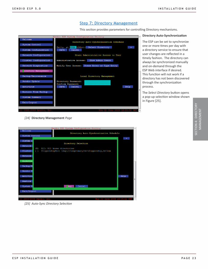
Step 7: Directory ManagementThis section provides parameters for controlling Directory mechanisms.
Directory Auto-Synchronization
The ESP can be set to synchronize one or more times per day with a directory service to ensure that user changes are reflected in a timely fashion. The directory can always be synchronized manually and on-demand through the ESP Web interface if desired. This function will not work if a directory has not been discovered through the synchronization process.
The Select Directory button opens a pop-up selection window shown in Figure [25].
[24] Directory Management Page
[25] Auto-Sync Directory Selection
SECT
ION
4:
DIRE
CTO
RY
MAN
AGEM
ENT
I N S T A L L A T I O N G U I D E S E N D I O E S P 5 . 0
PA G E 2 4 E s P I n s T A l l A T I o n G u I d E
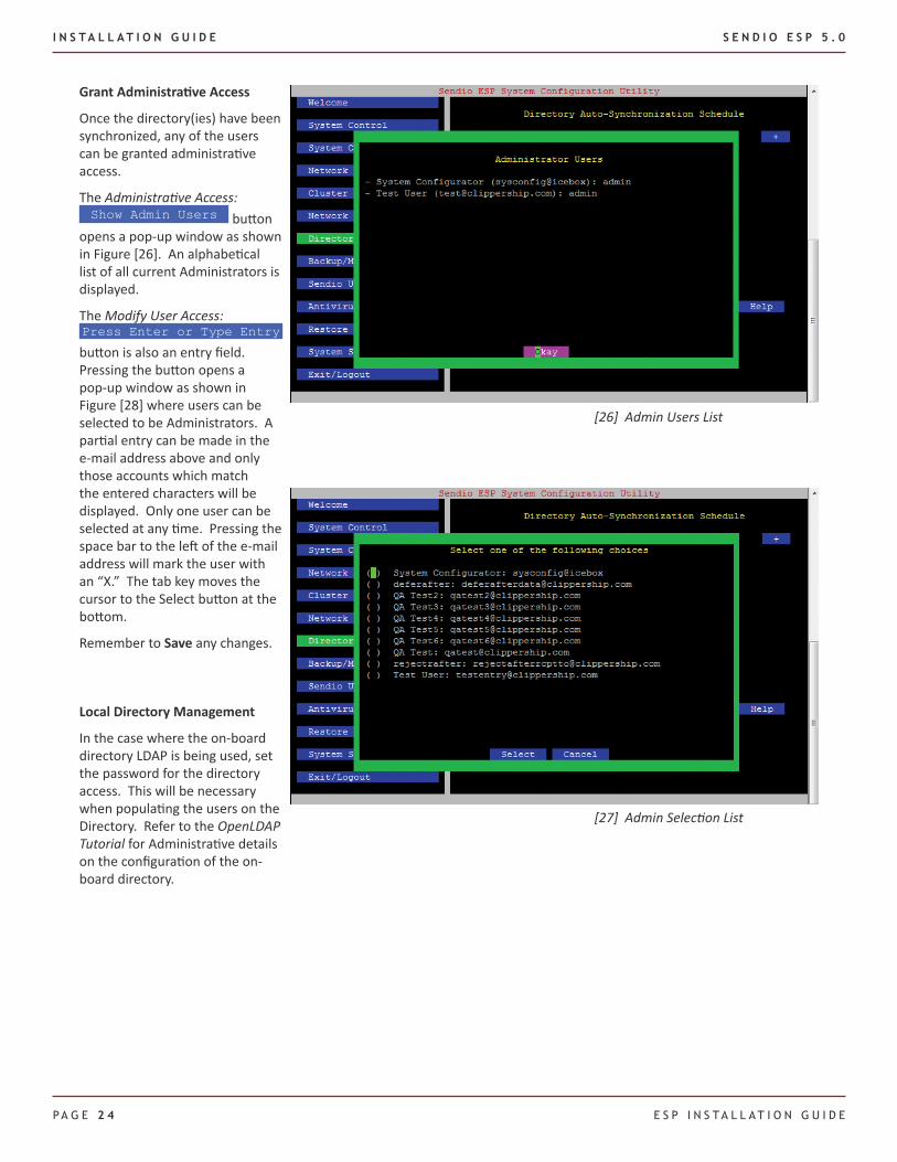
Grant Administrative Access
Once the directory(ies) have been synchronized, any of the users can be granted administrative access.
The Administrative Access: Show Admin Users button
opens a pop-up window as shown in Figure [26]. An alphabetical list of all current Administrators is displayed.
The Modify User Access: Press Enter or Type Entry button is also an entry field. Pressing the button opens a pop-up window as shown in Figure [28] where users can be selected to be Administrators. A partial entry can be made in the e-mail address above and only those accounts which match the entered characters will be displayed. Only one user can be selected at any time. Pressing the space bar to the left of the e-mail address will mark the user with an “X.” The tab key moves the cursor to the Select button at the bottom.
Remember to Save any changes.
Local Directory Management
In the case where the on-board directory LDAP is being used, set the password for the directory access. This will be necessary when populating the users on the Directory. Refer to the OpenLDAP Tutorial for Administrative details on the configuration of the on-board directory.
[26] Admin Users List
[27] Admin Selection List
S E N D I O E S P 5 . 0 I N S T A L L A T I O N G U I D E
E S P I N S T A L L A T I O N G U I D E P A G E 2 5
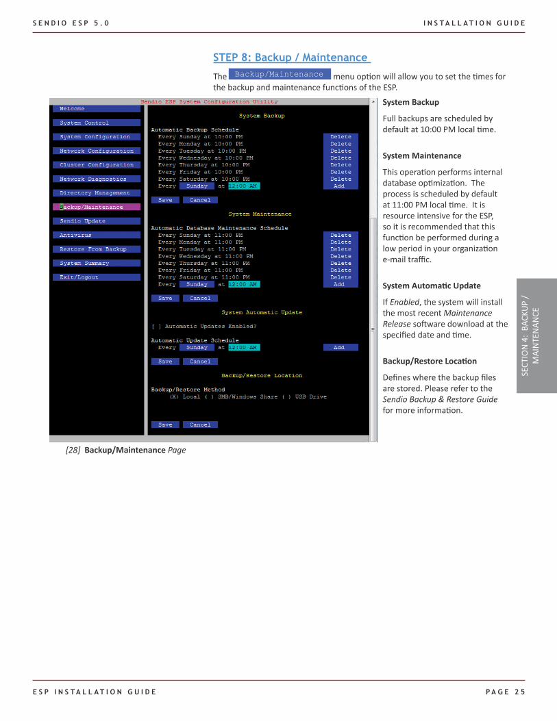
STEP 8: Backup / Maintenance
The Backup/Maintenance menu option will allow you to set the times for the backup and maintenance functions of the ESP.
[28] Backup/Maintenance Page
System Backup
Full backups are scheduled by default at 10:00 PM local time.
System Maintenance
This operation performs internal database optimization. The process is scheduled by default at 11:00 PM local time. It is resource intensive for the ESP, so it is recommended that this function be performed during a low period in your organization e-mail traffic.
System Automatic Update
If Enabled, the system will install the most recent Maintenance Release software download at the specified date and time.
Backup/Restore Location
Defines where the backup files are stored. Please refer to the Sendio Backup & Restore Guide for more information.
SECT
ION
4:
BACK
UP
/ M
AIN
TEN
ANCE
I N S T A L L A T I O N G U I D E S E N D I O E S P 5 . 0
PA G E 2 6 E s P I n s T A l l A T I o n G u I d E
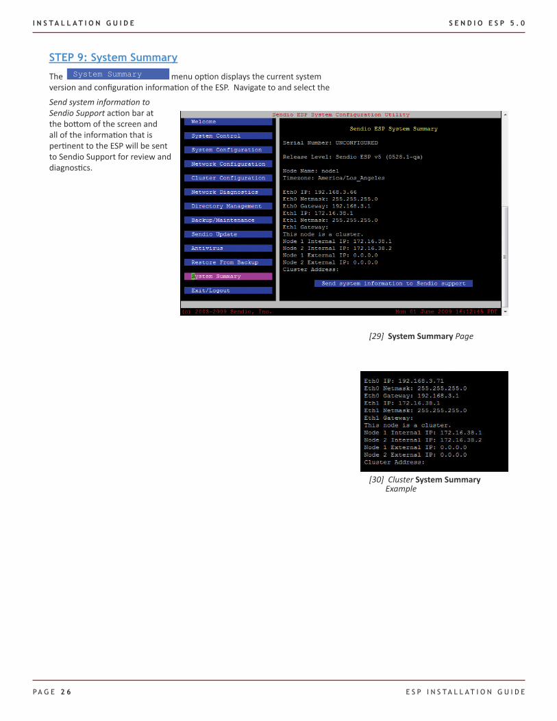
[29] System Summary Page
STEP 9: System Summary
The System Summary menu option displays the current system version and configuration information of the ESP. Navigate to and select the
Send system information to Sendio Support action bar at the bottom of the screen and all of the information that is pertinent to the ESP will be sent to Sendio Support for review and diagnostics.
[30] Cluster System Summary Example
S E N D I O E S P 5 . 0 I N S T A L L A T I O N G U I D E
E S P I N S T A L L A T I O N G U I D E P A G E 2 7
In order to finish the initial installation process, you must now use the Web interface to synchronize the ESP with a directory service such as Active Directory.
The following steps describe the general process for synchronization. The main points are:
Log in to the ESP Web interface using the ▪ sysconfig administrative user name
Navigate to the ▪ Domains pages and add the appropriate domains
Navigate to the ▪ Directories pages, create a new directory and synchronize it with a directory service
Refer to the Sendio ESP Administration Manual for more details on the Web interface.
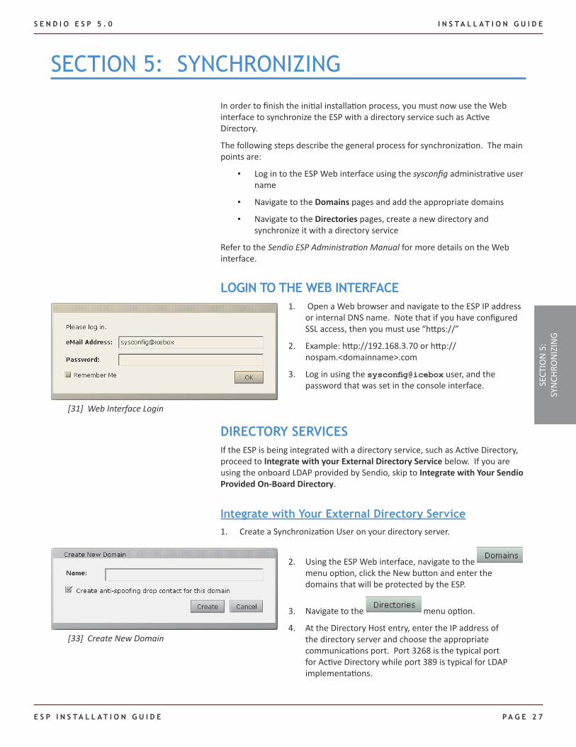
LOGIN TO THE WEB INTERFACE
sECTIon 5: sYnCHRonIZInG
Open a Web browser and navigate to the ESP IP address 1. or internal DNS name. Note that if you have configured SSL access, then you must use “https://”
Example: http://192.168.3.70 or http://2. nospam.<domainname>.com
Log in using the 3. sysconfig@icebox user, and the password that was set in the console interface.
DIRECTORY SERVICESIf the ESP is being integrated with a directory service, such as Active Directory, proceed to Integrate with your External Directory Service below. If you are using the onboard LDAP provided by Sendio, skip to Integrate with Your Sendio Provided On-Board Directory.
Integrate with Your External Directory Service Create a Synchronization User on your directory server.1.
Using the ESP Web interface, navigate to the 2. menu option, click the New button and enter the domains that will be protected by the ESP.
Navigate to the 3. menu option.
At the Directory Host entry, enter the IP address of 4. the directory server and choose the appropriate communications port. Port 3268 is the typical port for Active Directory while port 389 is typical for LDAP implementations.
[31] Web Interface Login
[33] Create New Domain
SECT
ION
5:
SYN
CHRO
NIZ
ING
I N S T A L L A T I O N G U I D E S E N D I O E S P 5 . 0
PA G E 2 8 E s P I n s T A l l A T I o n G u I d E
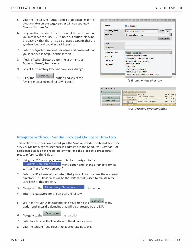
Click the “Fetch DNs” button and a drop-down list of the 5. DNs available on the target server will be populated. Choose the base DN.
Prepend the specific OU that you want to synchronize or 6. you may leave the Base DN. A note of Caution if leaving the base DN that there may be unused accounts that are synchronized and could impact licensing.
Enter the Synchronization User name and password that 7. you identified in Step 3 of this section.
If using Active Directory enter the user name as 8. Domain_Name\User_Name
Select the directory type and save your changes.9.
Click the 10. button and select the “synchronize selected directory” option.
Integrate with Your Sendio Provided On Board DirectoryThis section describes how to configure the Sendio-provided on-board directory service. Maintaining the user base is addressed in the Open LDAP Tutorial. For additional details on the required software and the associated procedures, please reference this Guide.
Using the ESP 1. sysconfig console interface, navigate to the System Configuration menu option and set the directory services to “start” and “always on boot.”
Enter the IP address of the system that you will use to access the on-board 2. directory. This IP address will be the system that is used to maintain the user base of this directory.
Navigate to the 3. Directory Management menu option.
Enter the password for the on-board directory.4.
Log in to the ESP Web interface, and navigate to the 5. menu option and enter the domains that will be protected by the ESP.
Navigate to the 6. menu option.
Enter localhost as the IP address of the directory server.7.
Click “Fetch DNs” and select the appropriate Base DN.8.
[33] Create New Directory
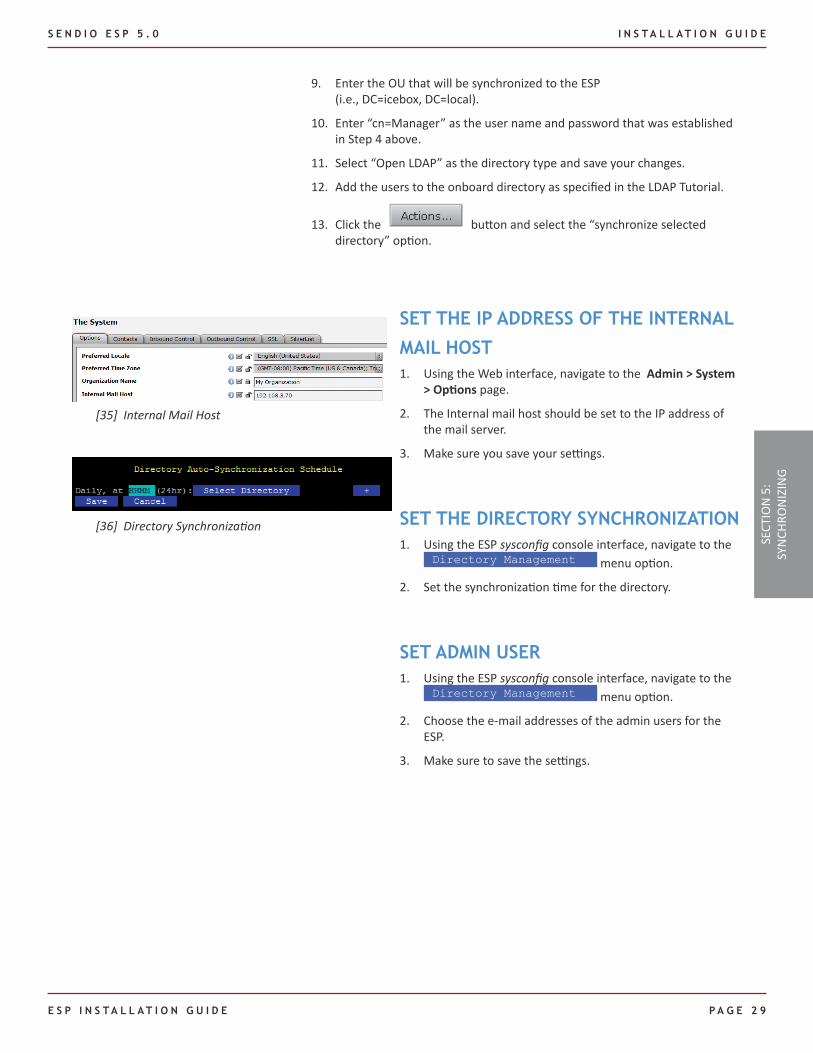
[34] Directory Synchronization
S E N D I O E S P 5 . 0 I N S T A L L A T I O N G U I D E
E S P I N S T A L L A T I O N G U I D E P A G E 2 9
Enter the OU that will be synchronized to the ESP 9. (i.e., DC=icebox, DC=local).
Enter “cn=Manager” as the user name and password that was established 10. in Step 4 above.
Select “Open LDAP” as the directory type and save your changes.11.
Add the users to the onboard directory as specified in the LDAP Tutorial.12.
Click the 13. button and select the “synchronize selected directory” option.
SECT
ION
5:
SYN
CHRO
NIZ
ING
SET THE IP ADDRESS OF THE INTERNAL
MAIL HOSTUsing the Web interface, navigate to the 1. Admin > System > Options page.
The Internal mail host should be set to the IP address of 2. the mail server.
Make sure you save your settings.3.
SET THE DIRECTORY SYNCHRONIZATIONUsing the ESP 1. sysconfig console interface, navigate to the Directory Management menu option.
Set the synchronization time for the directory.2.
SET ADMIN USERUsing the ESP 1. sysconfig console interface, navigate to the Directory Management menu option.
Choose the e-mail addresses of the admin users for the 2. ESP.
Make sure to save the settings.3.
[35] Internal Mail Host
[36] Directory Synchronization

I N S T A L L A T I O N G U I D E S E N D I O E S P 5 . 0
PA G E 3 0 E s P I n s T A l l A T I o n G u I d E
This page intentionally left blank
S E N D I O E S P 5 . 0 I N S T A L L A T I O N G U I D E
E S P I N S T A L L A T I O N G U I D E P A G E 3 1
sECTIon 6: RouTE E-MAIl TRAFFIC
System Contacts
Importing a list of e-mail addresses from an existing database is a vital component in the Sendio installation process. In almost all cases organizations have a CRM, database, address list or other information list containing e-mail addresses of customers, vendors, partners, etc. By importing this existing list all the contacts are automatically added to the Sendio Trusted Network and messages will be immediately delivered. Simply export the e-mail addresses from your existing application to a CSV and import the CSV in to the Sendio System Contacts. From day 1 you can have thousands of pre-approved e-mail addresses.
It is important that a few system contacts are implemented prior to sending traffic towards the ESP. Refer to the ESP Deployment Guide for details on the phased roll out of the Sendio ESP e-mail Integrity appliance. Using the GUI, create a System contact entry to accept all e-mail from Sendio Support by clicking Admin > System > Contacts > New.
IMPORTANT: If valid external entities that send inbound e-mails appearing from mydomain.com (e.g. an outsourced support center), create exceptions to the above rule to allow such e-mail traffic.
Create an Accept contact (Pre-User) to allow *@mydomain.com from the • specific IP address.
If external Blackberry users exist, create an Accept contact (Pre-User) for • the user’s envelope sender address pattern (typically *@*.blackberry.net). This address can be determined by examining the Return-Path of a sample message sent from the Blackberry user.
After the e-mail diagnostics test has been successful (described in Section 4 Step 4), the ESP will ready to protect your organization. On your firewall, direct inbound SMTP traffic (TCP port 25) to the IP address of your ESP (or, if the ESP has an external IP address, modify your domain’s MX record).
View the logs on the GUI to verify that traffic is flowing. Send a final test e-mail both inbound and outbound from an external account. reply to the SAV Request , and verify that the test message has been released from the Pending Queue.
NOTE: If an MX record has been changed, please note that the reply to the SAV message may not immediately follow the intended path to the ESP until the propgation delay associated with DNS modification has resolved the return path properly.
SECT
ION
6:
ROU
TE E
-mai
l TR
AFFI
C
Very Important!

I N S T A L L A T I O N G U I D E S E N D I O E S P 5 . 0
PA G E 3 2 E s P I n s T A l l A T I o n G u I d E
This page intentionally left blank
S E N D I O E S P 5 . 0 I N S T A L L A T I O N G U I D E
E S P I N S T A L L A T I O N G U I D E P A G E 3 3
Web-Based or Mobile e-mail AccessIf your organization uses Web-based e-mail access such as Outlook Web Access, ensure that the firewall access that has been modified such that the ESP does not interfere with this function. For example, if you have port 80 currently configured on your firewall for Web access to your MTA, and the ESP is inserted in this path, the Web access will not be available unless steps are taken.
Two possible ways to accommodate this access are:
Use port forwarding on the firewall to allow for port 80 to be sent directly 1. to the MTA. Note that this will eliminate external Web based access to the ESP Web interface.
Add an additional external IP address for this access. Note that there will 2. likely be MX record implications in this scenario.
If your organization uses wireless devices such as Blackberries or Windows mobile devices that utilize Active Sync, the insertion of the ESP into the messaging environment should be analyzed so that this service is not disrupted. Similar to the scenario for Web-based e-mail described earlier, network access must be preserved for these devices. Note that desktop synchronization will not be impacted in any way.
sECTIon 7: oTHER ConsIdERATIons
SECT
ION
7:
OTH
ER
CON
SIDE
RATI
ON
S

I N S T A L L A T I O N G U I D E S E N D I O E S P 5 . 0
PA G E 3 4 E s P I n s T A l l A T I o n G u I d E
This page intentionally left blank
S E N D I O E S P 5 . 0 I N S T A L L A T I O N G U I D E
E S P I N S T A L L A T I O N G U I D E P A G E 3 5
DNS (port 53) Access
This port provides the Distributed Naming Service (DNS) access to the ESP. This is a service that translates domain names into IP addresses. Because domain names are alphabetic, they’re easier to remember. The Internet, however, is really based on IP addresses. Every time you use a domain name, therefore, a DNS service must translate the name into the corresponding IP address. For example, the domain name www.example.com might translate to 198.105.232.4. The DNS system is, in fact, its own network. If one DNS server doesn’t know how to translate a particular domain name, it asks another one, and so on, until the correct IP address is returned.
External Address (Primary)
If you do not have an ESP cluster, this is the only external address you must provide. This is the public address that will be NAT’ed to the server so that it may be configured. Sendio uses this address to access the ESP when it is initially installed. As such, the accuracy of this address is very important.
External Cluster Address
If you have an ESP cluster, then you must provide a secondary address that is movable within the firewall. This address cannot be bound to a MAC address, or the ESP will not failover properly as intended.
External Network Gateway
Strictly speaking, a gateway is a means by which users of one computer system can gain access to another without making a separate connection. The external gateway is the address that is essentially provided by the ISP that allows other network components to access the firewall and external network.
Firewall Address
This is the public IP address of your firewall. This may or may not be the public-facing IP for your mail traffic, i.e. the MX record for your mail.
HTTP (port 80) Access
This port provides the ESP with a method to automatically update its internal software and provides GUI access to the ESP for end users and for administrative purposes.
HTTPS (port 443) Access
This port provides the ESP with a method to update its internal software automatically and provide GUI access to the ESP for end users and for administrative purposes.
Internal Cluster Address (Primary)
If you do not have an ESP cluster, then this is the only internal cluster address you must provide. This address is the internal address of the Sendio ESP that
GlossARY
GLO
SSAR
Y
I N S T A L L A T I O N G U I D E S E N D I O E S P 5 . 0
PA G E 3 6 E s P I n s T A l l A T I o n G u I d E
allows the secure connection from the internet. In many cases, this address begins with a 10.xxx.xxx.xxx or 192.168.xxx.xxx.
Internal Cluster Address (Secondary)
If you have an ESP cluster, then you must provide a secondary address that is movable within the firewall. This address cannot be bound to a MAC address, or the ESP will not failover properly as intended.
Internal Mail Gateway
The address of the e-mail server where the ESP should deliver mail after processing. This should be an internal address. If the ESP and the mail server are on different LAN segments or cross a DMZ, it is imperative that the firewall is configured in such a way as to allow access from the ESP to the mail server.
Internal Network Gateway
This is the internal network address that the ESP and other network components will use to access the outside world.
LDAP Communication URL
The LDAP Communication URL is sometimes called the Active Directory URL. The ESP communicates with your Connection Directory Server through this URL for address and account synchronization. For proper functionality, the ESP must have a valid connection to an LDAP compliant domain controller. The common ports for this communication are 389 for LDAP users or 3268 for Microsoft’s Global Catalog.
LDAP Username/Password
The ESP requires a user name and password for proper connectivity to the Domain Controller on your network. This user does not need a mail box, requires only basic permissions, and the password must be set to never expire.
MTA Mail Transfer Authority
This abbreviation is the generic term that references the server that processes the messaging within an organization. Typical examples are Exchange and Lotus Notes.
NTP (port 123) Access
The Network Time Protocol (NTP) port allows time synchronization between devices. Bidirectional access is required. If you do not want to provide this access to Sendio, you will need to provide the name and address of an internal time server.
SMTP (port 25) Access
The Simple Mail Transport Protocol (SMTP) port provides basic communication between the ESP and other mail servers on your network and on the Internet. Port 25 is required for sending SAV requests, and as such requires the ability to originate and complete connections on port 25. Note that this is NOT an open relay. Make sure that the ESP is permitted to make unrestricted connections
S E N D I O E S P 5 . 0 I N S T A L L A T I O N G U I D E
E S P I N S T A L L A T I O N G U I D E P A G E 3 7
to your Exchange server for SMTP. Disable any rate limiting, as the ESP will become the sole source of traffic to your mail server.
SSH (port 22) Access
Secure shell is a program to log into another computer over a network, to execute commands in a remote machine, and to move files from one machine to another. It provides strong authentication and secure communications over insecure channels. This port provides the ESP with a method to automatically update its internal software and to provide Sendio access to the server for maintenance, troubleshooting or updates.
GLO
SSAR
Y

I N S T A L L A T I O N G U I D E S E N D I O E S P 5 . 0
PA G E 3 8 E s P I n s T A l l A T I o n G u I d E
This page intentionally left blank
S E N D I O E S P 5 . 0 I N S T A L L A T I O N G U I D E
E S P I N S T A L L A T I O N G U I D E P A G E 3 9
APPEndIX A: RACK MounTInG
Typically, an ESP server is rack-mounted in an IT equipment room. This Appendix describes how to attach rack-mount rails to the system and install it in various types of racks.
There are a variety of rack units on the market, which may mean the assembly procedure will differ slightly. The following is a guideline for installing the unit into a rack with the rack rails provided with the system. You should also refer to the installation instructions that came with the rack you are using.
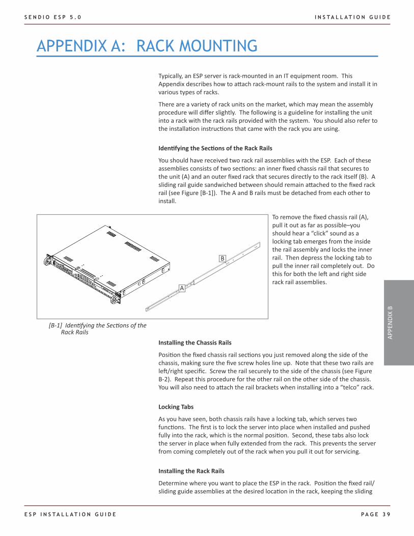
Identifying the Sections of the Rack Rails
You should have received two rack rail assemblies with the ESP. Each of these assemblies consists of two sections: an inner fixed chassis rail that secures to the unit (A) and an outer fixed rack that secures directly to the rack itself (B). A sliding rail guide sandwiched between should remain attached to the fixed rack rail (see Figure [B-1]). The A and B rails must be detached from each other to install.
A
B
[B-1] Identifying the Sections of the Rack Rails
To remove the fixed chassis rail (A), pull it out as far as possible–you should hear a “click” sound as a locking tab emerges from the inside the rail assembly and locks the inner rail. Then depress the locking tab to pull the inner rail completely out. Do this for both the left and right side rack rail assemblies.
Installing the Chassis Rails
Position the fixed chassis rail sections you just removed along the side of the chassis, making sure the five screw holes line up. Note that these two rails are left/right specific. Screw the rail securely to the side of the chassis (see Figure B-2). Repeat this procedure for the other rail on the other side of the chassis. You will also need to attach the rail brackets when installing into a “telco” rack.
Locking Tabs
As you have seen, both chassis rails have a locking tab, which serves two functions. The first is to lock the server into place when installed and pushed fully into the rack, which is the normal position. Second, these tabs also lock the server in place when fully extended from the rack. This prevents the server from coming completely out of the rack when you pull it out for servicing.
Installing the Rack Rails
Determine where you want to place the ESP in the rack. Position the fixed rail/sliding guide assemblies at the desired location in the rack, keeping the sliding
APPE
NDI
X B
I N S T A L L A T I O N G U I D E S E N D I O E S P 5 . 0
PA G E 4 0 E s P I n s T A l l A T I o n G u I d E
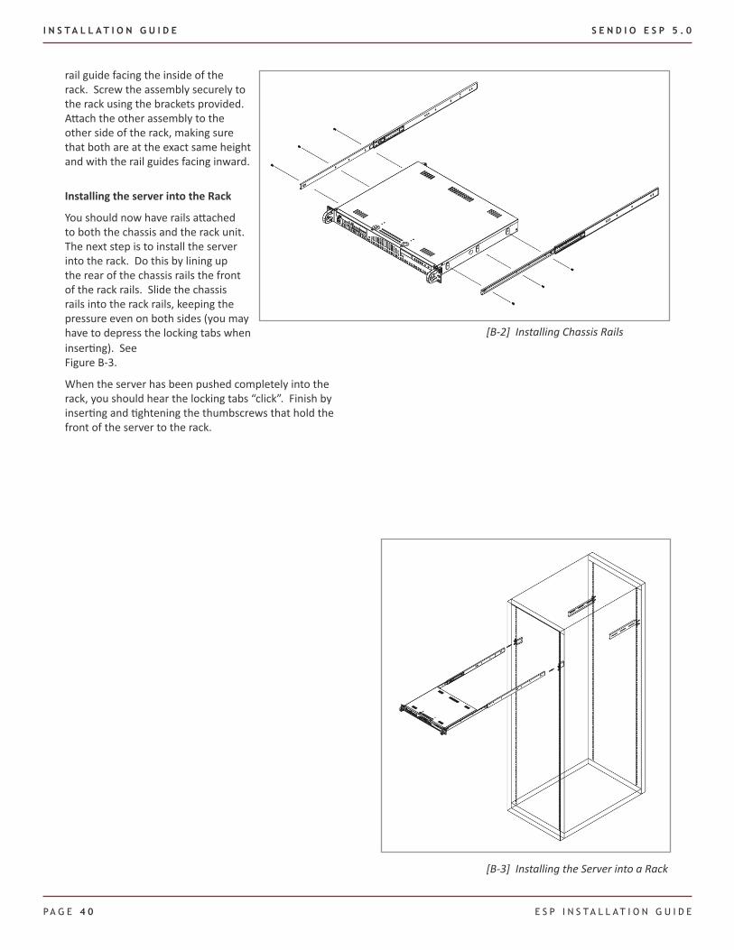
inserting). See Figure B-3.
When the server has been pushed completely into the rack, you should hear the locking tabs “click”. Finish by inserting and tightening the thumbscrews that hold the front of the server to the rack.
[B-2] Installing Chassis Rails
rail guide facing the inside of the rack. Screw the assembly securely to the rack using the brackets provided. Attach the other assembly to the other side of the rack, making sure that both are at the exact same height and with the rail guides facing inward.
Installing the server into the Rack
You should now have rails attached to both the chassis and the rack unit. The next step is to install the server into the rack. Do this by lining up the rear of the chassis rails the front of the rack rails. Slide the chassis rails into the rack rails, keeping the pressure even on both sides (you may have to depress the locking tabs when
[B-3] Installing the Server into a Rack
S E N D I O E S P 5 . 0 I N S T A L L A T I O N G U I D E
E S P I N S T A L L A T I O N G U I D E P A G E 4 1
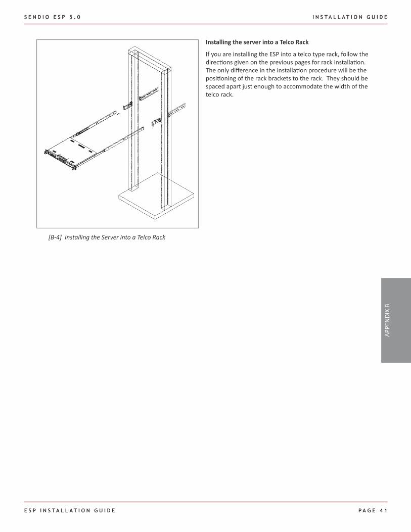
Installing the server into a Telco Rack
If you are installing the ESP into a telco type rack, follow the directions given on the previous pages for rack installation. The only difference in the installation procedure will be the positioning of the rack brackets to the rack. They should be spaced apart just enough to accommodate the width of the telco rack.
[B-4] Installing the Server into a Telco Rack
APPE
NDI
X B

The eMail Integrity Company
Sendio, Inc.1176 Main Street, Suite C
Irvine, CA 62614 USA
+1.949.274.4375
www.sendio.com
The e-mail Integrity Company